Linear Motion andAssembly Technologies ServicePneumaticsHydraulics
Electric Drives and Controls
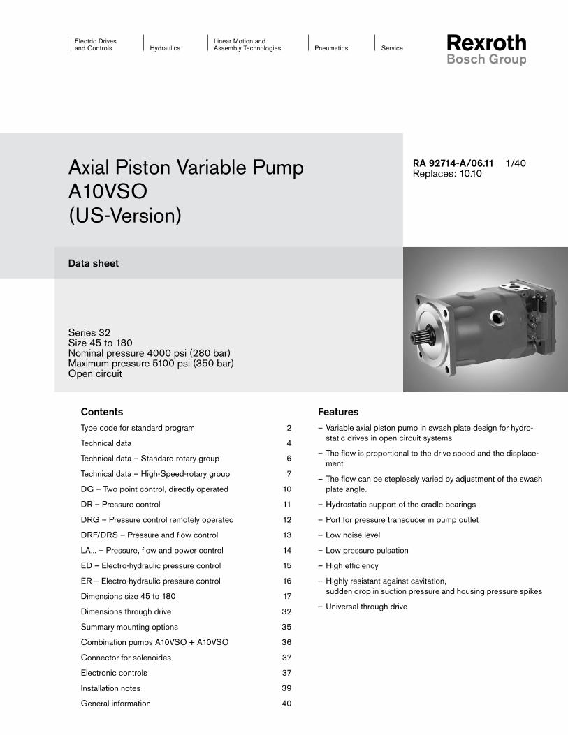
Series 32 Size 45 to 180Nominal pressure 4000 psi (280 bar)Maximum pressure 5100 psi (350 bar)Open circuit
FeaturesVariable axial piston pump in swash plate design for hydro- –static drives in open circuit systems
The flow is proportional to the drive speed and the displace- –ment
The flow can be steplessly varied by adjustment of the swash –plate angle.
Hydrostatic support of the cradle bearings –
Port for pressure transducer in pump outlet –
Low noise level –
Low pressure pulsation –
High efficiency –
Highly resistant against cavitation, –sudden drop in suction pressure and housing pressure spikes
Universal through drive –
RA 92714-A/06.11 1/40Replaces: 10.10Axial Piston Variable Pump
A10VSO (US-Version)
Data sheet Position Foto (oben links):X = 153Y = 93,9
ContentsType code for standard program 2
Technical data 4
Technical data – Standard rotary group 6
Technical data – High-Speed-rotary group 7
DG – Two point control, directly operated 10
DR – Pressure control 11
DRG – Pressure control remotely operated 12
DRF/DRS – Pressure and flow control 13
LA... – Pressure, flow and power control 14
ED – Electro-hydraulic pressure control 15
ER – Electro-hydraulic pressure control 16
Dimensions size 45 to 180 17
Dimensions through drive 32
Summary mounting options 35
Combination pumps A10VSO + A10VSO 36
Connector for solenoides 37
Electronic controls 37
Installation notes 39
General information 40
A10VSO Series 32 RA 92714-A/06.112/40 Bosch Rexroth Corp.
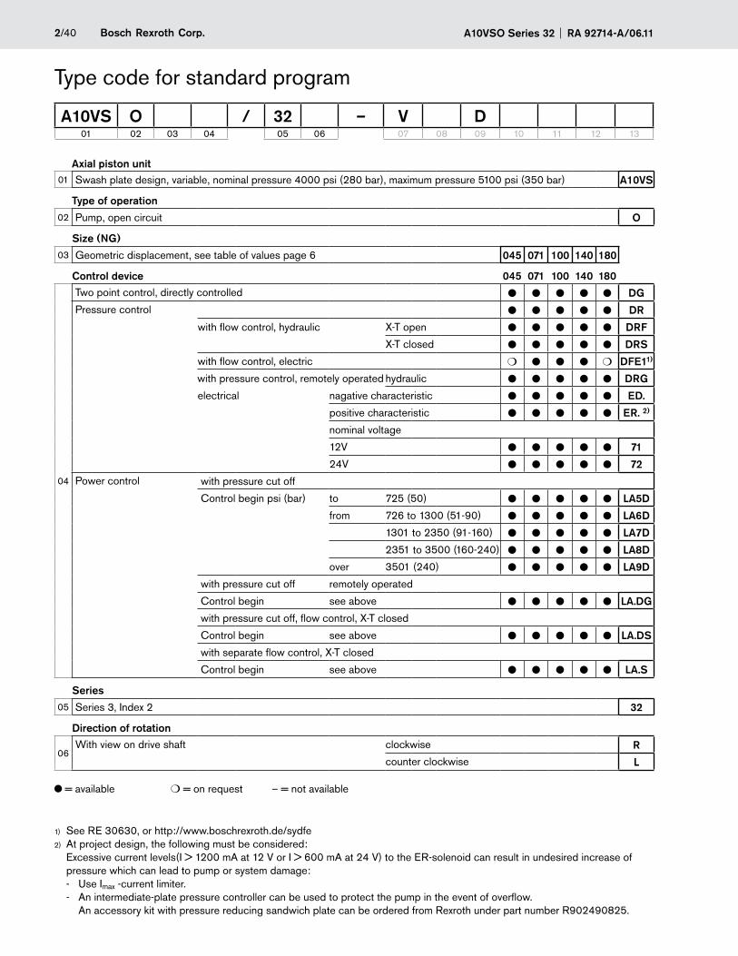
Axial piston unit01 Swash plate design, variable, nominal pressure 4000 psi (280 bar), maximum pressure 5100 psi (350 bar) A10VS
Type of operation02 Pump, open circuit O
Size (NG)03 Geometric displacement, see table of values page 6 045 071 100 140 180
Control device 045 071 100 140 180
04
Two point control, directly controlled l l l l l DG
Pressure control l l l l l DR
with flow control, hydraulic X-T open l l l l l DRF
X-T closed l l l l l DRS
with flow control, electric m l l l m DFE11)
with pressure control, remotely operated hydraulic l l l l l DRG
electrical nagative characteristic l l l l l ED.
positive characteristic l l l l l ER. 2)
nominal voltage
12V l l l l l 71
24V l l l l l 72
Power control with pressure cut off
Control begin psi (bar) to 725 (50) l l l l l LA5D
from 726 to 1300 (51-90) l l l l l LA6D
1301 to 2350 (91-160) l l l l l LA7D
2351 to 3500 (160-240) l l l l l LA8D
over 3501 (240) l l l l l LA9D
with pressure cut off remotely operated
Control begin see above l l l l l LA.DG
with pressure cut off, flow control, X-T closed
Control begin see above l l l l l LA.DS
with separate flow control, X-T closed
Control begin see above l l l l l LA.S
Series05 Series 3, Index 2 32
Direction of rotation
06With view on drive shaft clockwise R
counter clockwise L
Type code for standard program
A10VS O / 32 – V D01 02 03 04 05 06 07 08 09 10 11 12 13
See RE 30630, or http://www.boschrexroth.de/sydfe1)
At project design, the following must be considered: 2)
Excessive current levels(I > 1200 mA at 12 V or I > 600 mA at 24 V) to the ER-solenoid can result in undesired increase of pressure which can lead to pump or system damage: - Use Imax -current limiter. - An intermediate-plate pressure controller can be used to protect the pump in the event of overflow. An accessory kit with pressure reducing sandwich plate can be ordered from Rexroth under part number R902490825.
= available m = on request – = not available
3/40Bosch Rexroth Corp.RA 92714-A/06.11 A10VSO Series 32
Type code for standard program
A10VS O / 32 – V D01 02 03 04 05 06 07 08 09 10 11 12 13
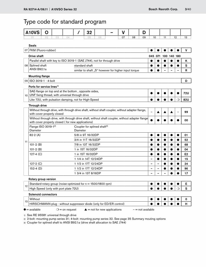
Seals07 FKM (Fluoro-rubber) l l l l l V
Drive shaft 045 071 100 140 180
08
Parallel shaft with key to ISO 3019-1 (SAE J744), not for through drive l l l l l K
Splined shaft ANSI B92.1a
standard shaft l l l l l S
similar to shaft „S“ however for higher input torque l l – – – R
Mounting flange09 ISO 3019-1 - 4-bolt D
Ports for service lines1)
10
SAE-flange on top and at the bottom , opposite sides, UNF fixing thread, with universal through drive l l l l l 72U
Like 72U, with pulsation damping, not for High-Speed l l l l m 82U
Through drive
11
Without through drive, with through drive shaft, without shaft coupler, without adapter flange, with cover properly closed
– ▲ ▲ ▲ – 99
Without through drive, with through drive shaft, without shaft coupler, without adapter flange with cover properly closed ( for new applications) l l l l l 00
Flange ISO 3019-12) Diameter
Coupler for splined shaft3) Diameter
82-2 (A) 5/8 in 9T 16/32DP l l l l l 01
3/4 in 11T 16/32DP l l l l l 52
101-2 (B) 7/8 in 13T 16/32DP l l l l l 68
101-2 (B) 1 in 15T 16/32DP l l l l l 04
127-4 (C) 1 in 15T 16/32DP l l l l l E2
1 1/4 in 14T 12/24DP – l l l l 15
127-2 (C) 1 1/2 in 17T 12/24DP – – l l l 24
152-4 (D) 1 1/2 in 17T 12/24DP – – l l l 96
1 3/4 in 13T 8/16DP – – – l l 17
Rotary group version
12Standard-rotary group (noise-optimized for n = 1500/1800 rpm) l l l l l E
High Speed (only with port plate 72U) l l l l m S
Solenoid connectors
13Without l l l l l 0
HIRSCHMANN-plug - without suppressor diode (only for ED/ER control) l l l l l H
= available m = on request ▲ = not for new applications – = not available
See RE 95581 universal through drive1)
2-bolt: mounting pump series 31; 4-bolt: mounting pump series 32. See page 35 Summary mouting options2)
Coupler for splined shaft to ANSI B92.1a (drive shaft allocation to SAE J744)3)
A10VSO Series 32 RA 92714-A/06.114/40 Bosch Rexroth Corp.
Technical dataFluidsPrior to project design, please see our technical data sheets RE 90220 (mineral oil) and RE 90221 (environmentally ac-ceptable fluids) for detailed information on fluids and operating conditions.
When using environmentally acceptable hydraulic fluids, the limitations regarding technical data and seals must be observed. Please contact us.
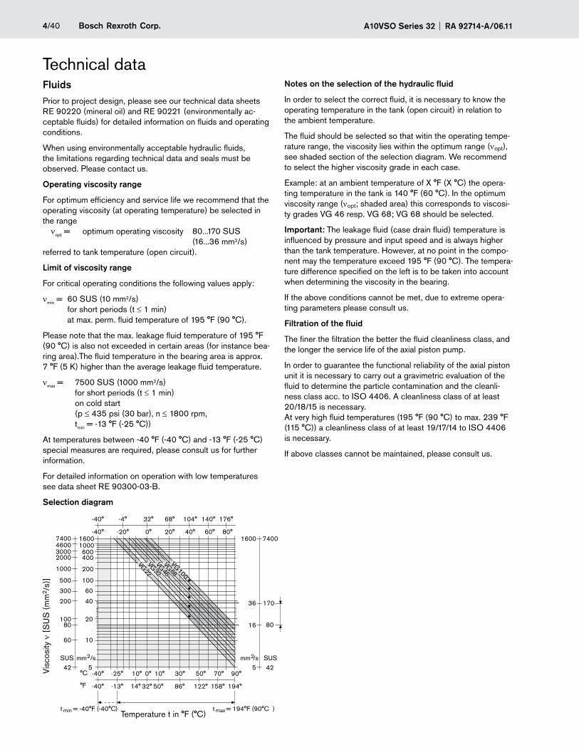
Operating viscosity range
For optimum efficiency and service life we recommend that the operating viscosity (at operating temperature) be selected in the range nopt = optimum operating viscosity 80...170 SUS (16...36 mm2/s) referred to tank temperature (open circuit).
Limit of viscosity range
For critical operating conditions the following values apply:
nmin = 60 SUS (10 mm2/s) for short periods (t ≤1 min) at max. perm. fluid temperature of 195 °F (90 °C).
Please note that the max. leakage fluid temperature of 195 °F (90 °C) is also not exceeded in certain areas (for instance bea-ring area).The fluid temperature in the bearing area is approx. 7 °F (5 K) higher than the average leakage fluid temperature.
nmax = 7500 SUS (1000 mm2/s) for short periods (t ≤1 min) on cold start (p ≤435 psi (30 bar), n ≤ 1800 rpm, tmin = -13 °F (-25 °C))
At temperatures between -40 °F (-40 °C) and -13 °F (-25 °C) special measures are required, please consult us for further information.
For detailed information on operation with low temperatures see data sheet RE 90300-03-B.
Selection diagram
Notes on the selection of the hydraulic fluid
In order to select the correct fluid, it is necessary to know the operating temperature in the tank (open circuit) in relation to the ambient temperature.
The fluid should be selected so that witin the operating tempe-rature range, the viscosity lies within the optimum range (nopt), see shaded section of the selection diagram. We recommend to select the higher viscosity grade in each case.
Example: at an ambient temperature of X °F (X °C) the opera-ting temperature in the tank is 140 °F (60 °C). In the optimum viscosity range (nopt; shaded area) this corresponds to viscosi-ty grades VG 46 resp. VG 68; VG 68 should be selected.
Important: The leakage fluid (case drain fluid) temperature is influenced by pressure and input speed and is always higher than the tank temperature. However, at no point in the compo-nent may the temperature exceed 195 °F (90 °C). The tempera-ture difference specified on the left is to be taken into account when determining the viscosity in the bearing.
If the above conditions cannot be met, due to extreme opera-ting parameters please consult us.
Filtration of the fluid
The finer the filtration the better the fluid cleanliness class, and the longer the service life of the axial piston pump.
In order to guarantee the functional reliability of the axial piston unit it is necessary to carry out a gravimetric evaluation of the fluid to determine the particle contamination and the cleanli-ness class acc. to ISO 4406. A cleanliness class of at least 20/18/15 is necessary. At very high fluid temperatures (195 °F (90 °C) to max. 239 °F (115 °C)) a cleanliness class of at least 19/17/14 to ISO 4406 is necessary.
If above classes cannot be maintained, please consult us.
-40° -4° 32° 68° 104° 140° 176°
-40° -20° 0° 20° 40° 60° 80°
-40° -25° 10° 0° 10° 30° 50° 70° 90°
-40° -13° 14° 32° 50° 86° 122° 158° 194°
160074001000460060030004002000
2001000
100500
60300
40200
20100
1060
mm2/sSUS542
80
74001600
17036
8016
425SUSmm2/s
t max = 194°F (90°C )t min = -40°F (-40°C
°C
°F
)
VG 22VG 32VG 46VG 68VG 100
Visc
osity
n [
SU
S (
mm
2 /s)
]
Temperature t in °F (°C)
5/40Bosch Rexroth Corp.RA 92714-A/06.11 A10VSO Series 32
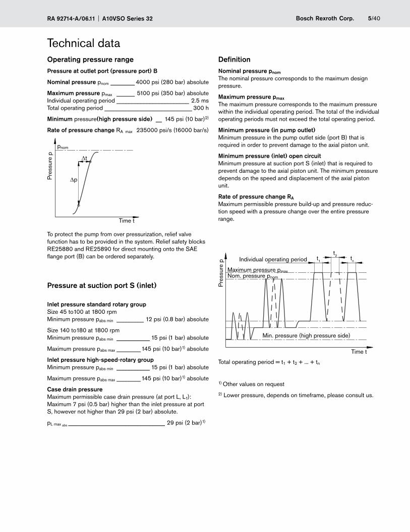
Technical dataOperating pressure rangePressure at outlet port (pressure port) B
Nominal pressure pnom ________ 4000 psi (280 bar) absolute
Maximum pressure pmax ______ 5100 psi (350 bar) absolute Individual operating period ________________________ 2.5 ms Total operating period _____________________________ 300 h
Minimum pressure(high pressure side) __ 145 psi (10 bar)2)
Rate of pressure change RA max 235000 psi/s (16000 bar/s)
pnom
Dt
Dp
Time t
Pre
ssur
e p
To protect the pump from over pressurization, relief valve function has to be provided in the system. Relief safety blocks RE25880 and RE25890 for direct mounting onto the SAE flange port (B) can be ordered separately.
Pressure at suction port S (inlet)
Inlet pressure standard rotary groupSize 45 to100 at 1800 rpm Minimum pressure pabs min _________ 12 psi (0.8 bar) absolute
Size 140 to180 at 1800 rpm Minimum pressure pabs min ___________ 15 psi (1 bar) absolute
Maximum pressure pabs max ________145 psi (10 bar)1) absolute
Inlet pressure high-speed-rotary groupMinimum pressure pabs min ___________ 15 psi (1 bar) absolute
Maximum pressure pabs max ________145 psi (10 bar)1) absolute
Case drain pressureMaximum permissible case drain pressure (at port L, L1): Maximum 7 psi (0.5 bar) higher than the inlet pressure at port S, however not higher than 29 psi (2 bar) absolute.
pL max abs ________________________________ 29 psi (2 bar)1)
DefinitionNominal pressure pnom
The nominal pressure corresponds to the maximum design pressure.
Maximum pressure pmax
The maximum pressure corresponds to the maximum pressure within the individual operating period. The total of the individual operating periods must not exceed the total operating period.
Minimum pressure (in pump outlet)Minimum pressure in the pump outlet side (port B) that is required in order to prevent damage to the axial piston unit.
Minimum pressure (inlet) open circuitMinimum pressure at suction port S (inlet) that is required to prevent damage to the axial piston unit. The minimum pressure depends on the speed and displacement of the axial piston unit.
Rate of pressure change RA
Maximum permissible pressure build-up and pressure reduc-tion speed with a pressure change over the entire pressure range.
Pre
ssur
e p t1
t2 tnIndividual operating period
Min. pressure (high pressure side)
Maximum pressure pmaxNom. pressure pnom
Time t
Total operating period = t1 + t2 + ... + tn
1) Other values on request
2) Lower pressure, depends on timeframe, please consult us.
A10VSO Series 32 RA 92714-A/06.116/40 Bosch Rexroth Corp.
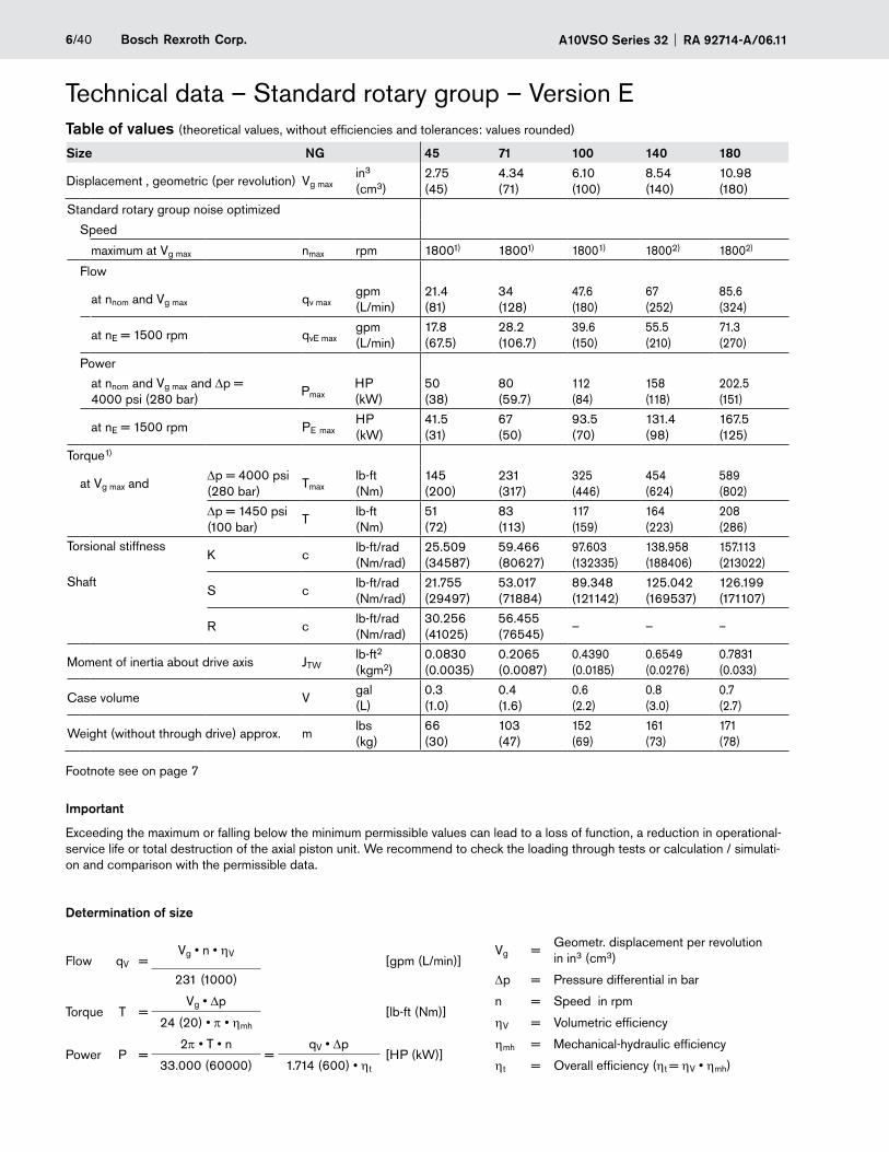
Technical data – Standard rotary group – Version ETable of values (theoretical values, without efficiencies and tolerances: values rounded)
Size NG 45 71 100 140 180
Displacement , geometric (per revolution) Vg maxin3 (cm3)
2.75 (45)
4.34 (71)
6.10 (100)
8.54 (140)
10.98 (180)
Standard rotary group noise optimized
Speed
maximum at Vg max nmax rpm 18001) 18001) 18001) 18002) 18002)
Flow
at nnom and Vg max qv maxgpm (L/min)
21.4 (81)
34 (128)
47.6 (180)
67 (252)
85.6 (324)
at nE = 1500 rpm qvE maxgpm (L/min)
17.8 (67.5)
28.2 (106.7)
39.6 (150)
55.5 (210)
71.3 (270)
Power
at nnom and Vg max and Dp = 4000 psi (280 bar)
PmaxHP (kW)
50 (38)
80 (59.7)
112 (84)
158 (118)
202.5 (151)
at nE = 1500 rpm PE maxHP (kW)
41.5 (31)
67 (50)
93.5 (70)
131.4 (98)
167.5 (125)
Torque1)
at Vg max andDp = 4000 psi (280 bar)
Tmaxlb-ft (Nm)
145 (200)
231 (317)
325 (446)
454 (624)
589 (802)
Dp = 1450 psi (100 bar)
Tlb-ft (Nm)
51 (72)
83 (113)
117 (159)
164 (223)
208 (286)
Torsional stiffnessK c
lb-ft/rad (Nm/rad)
25.509 (34587)
59.466 (80627)
97.603 (132335)
138.958 (188406)
157.113 (213022)
ShaftS c
lb-ft/rad (Nm/rad)
21.755 (29497)
53.017 (71884)
89.348 (121142)
125.042 (169537)
126.199 (171107)
R clb-ft/rad (Nm/rad)
30.256 (41025)
56.455 (76545)
– – –
Moment of inertia about drive axis JTWlb-ft2 (kgm2)
0.0830 (0.0035)
0.2065 (0.0087)
0.4390 (0.0185)
0.6549 (0.0276)
0.7831 (0.033)
Case volume Vgal (L)
0.3 (1.0)
0.4 (1.6)
0.6 (2.2)
0.8 (3.0)
0.7 (2.7)
Weight (without through drive) approx. mlbs (kg)
66 (30)
103 (47)
152 (69)
161 (73)
171 (78)
Footnote see on page 7
Important
Exceeding the maximum or falling below the minimum permissible values can lead to a loss of function, a reduction in operational-service life or total destruction of the axial piston unit. We recommend to check the loading through tests or calculation / simulati-on and comparison with the permissible data.
Determination of size
Flow qV =Vg • n • hV
[gpm (L/min)]Vg =
Geometr. displacement per revolution in in3 (cm3)
231 (1000) Dp = Pressure differential in bar
Torque T =Vg • Dp
[lb-ft (Nm)]n = Speed in rpm
24 (20) • p • hmh hV = Volumetric efficiency
Power P =2p • T • n
=qV • Dp
[HP (kW)]hmh = Mechanical-hydraulic efficiency
33.000 (60000) 1.714 (600) • ht ht = Overall efficiency (ht = hV • hmh)
7/40Bosch Rexroth Corp.RA 92714-A/06.11 A10VSO Series 32
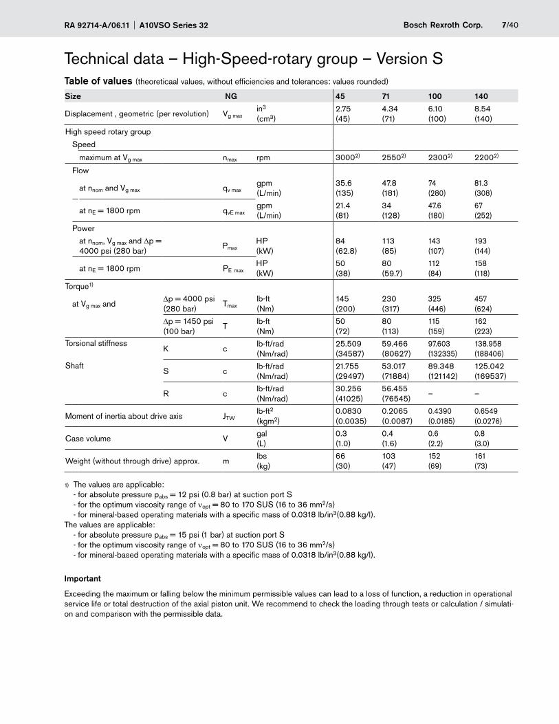
Technical data – High-Speed-rotary group – Version STable of values (theoreticaal values, without efficiencies and tolerances: values rounded)
Size NG 45 71 100 140
Displacement , geometric (per revolution) Vg maxin3 (cm3)
2.75 (45)
4.34 (71)
6.10 (100)
8.54 (140)
High speed rotary group
Speed
maximum at Vg max nmax rpm 30002) 25502) 23002) 22002)
Flow
at nnom and Vg max qv maxgpm (L/min)
35.6 (135)
47.8 (181)
74 (280)
81.3 (308)
at nE = 1800 rpm qvE maxgpm (L/min)
21.4 (81)
34 (128)
47.6 (180)
67 (252)
Power
at nnom, Vg max and Dp = 4000 psi (280 bar)
PmaxHP (kW)
84 (62.8)
113 (85)
143 (107)
193 (144)
at nE = 1800 rpm PE maxHP (kW)
50 (38)
80 (59.7)
112 (84)
158 (118)
Torque1)
at Vg max andDp = 4000 psi (280 bar)
Tmaxlb-ft (Nm)
145 (200)
230 (317)
325 (446)
457 (624)
Dp = 1450 psi (100 bar)
Tlb-ft (Nm)
50 (72)
80 (113)
115 (159)
162 (223)
Torsional stiffnessK c
lb-ft/rad (Nm/rad)
25.509 (34587)
59.466 (80627)
97.603 (132335)
138.958 (188406)
ShaftS c
lb-ft/rad (Nm/rad)
21.755 (29497)
53.017 (71884)
89.348 (121142)
125.042 (169537)
R clb-ft/rad (Nm/rad)
30.256 (41025)
56.455 (76545)
– –
Moment of inertia about drive axis JTWlb-ft2 (kgm2)
0.0830 (0.0035)
0.2065 (0.0087)
0.4390 (0.0185)
0.6549 (0.0276)
Case volume Vgal (L)
0.3 (1.0)
0.4 (1.6)
0.6 (2.2)
0.8 (3.0)
Weight (without through drive) approx. mlbs (kg)
66 (30)
103 (47)
152 (69)
161 (73)
The values are applicable: 1)
- for absolute pressure pabs = 12 psi (0.8 bar) at suction port S - for the optimum viscosity range of nopt = 80 to 170 SUS (16 to 36 mm2/s) - for mineral-based operating materials with a specific mass of 0.0318 lb/in3(0.88 kg/l).
The values are applicable: - for absolute pressure pabs = 15 psi (1 bar) at suction port S - for the optimum viscosity range of nopt = 80 to 170 SUS (16 to 36 mm2/s) - for mineral-based operating materials with a specific mass of 0.0318 lb/in3(0.88 kg/l).
Important
Exceeding the maximum or falling below the minimum permissible values can lead to a loss of function, a reduction in operational service life or total destruction of the axial piston unit. We recommend to check the loading through tests or calculation / simulati-on and comparison with the permissible data.
A10VSO Series 32 RA 92714-A/06.118/40 Bosch Rexroth Corp.
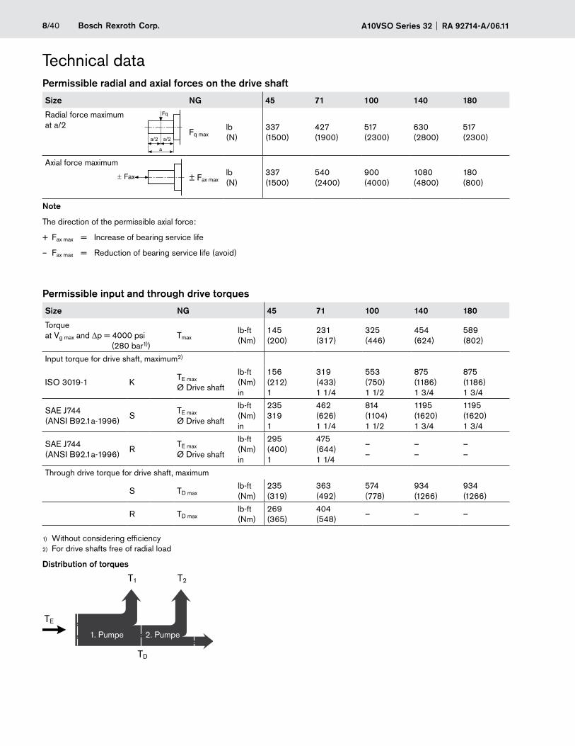
Technical dataPermissible radial and axial forces on the drive shaft
Size NG 45 71 100 140 180
Radial force maximum at a/2
Fq maxlb (N)
337 (1500)
427 (1900)
517 (2300)
630 (2800)
517 (2300)
Axial force maximum
± Fax maxlb (N)
337 (1500)
540 (2400)
900 (4000)
1080 (4800)
180 (800)
Note
The direction of the permissible axial force:
+ Fax max = Increase of bearing service life
– Fax max = Reduction of bearing service life (avoid)
Permissible input and through drive torques
Size NG 45 71 100 140 180
Torque at Vg max and Dp = 4000 psi (280 bar1))
Tmaxlb-ft (Nm)
145 (200)
231 (317)
325 (446)
454 (624)
589 (802)
Input torque for drive shaft, maximum2)
ISO 3019-1 KTE max
Ø Drive shaft
lb-ft (Nm) in
156 (212) 1
319 (433) 1 1/4
553 (750) 1 1/2
875 (1186) 1 3/4
875 (1186) 1 3/4
SAE J744 (ANSI B92.1a-1996)
STE max
Ø Drive shaft
lb-ft (Nm) in
235 319 1
462 (626) 1 1/4
814 (1104) 1 1/2
1195 (1620) 1 3/4
1195 (1620) 1 3/4
SAE J744 (ANSI B92.1a-1996)
RTE max
Ø Drive shaft
lb-ft (Nm) in
295 (400) 1
475 (644) 1 1/4
– –
– –
– –
Through drive torque for drive shaft, maximum
S TD maxlb-ft (Nm)
235 (319)
363 (492)
574 (778)
934 (1266)
934 (1266)
R TD maxlb-ft (Nm)
269 (365)
404 (548)
– – –
Without considering efficiency1)
For drive shafts free of radial load2)
Distribution of torques
2. Pumpe1. Pumpe
TE
TD
T1 T2
± Fax
Fq
a
a/2 a/2
1. Pumpe 2. Pumpe
9/40Bosch Rexroth Corp.RA 92714-A/06.11 A10VSO Series 32
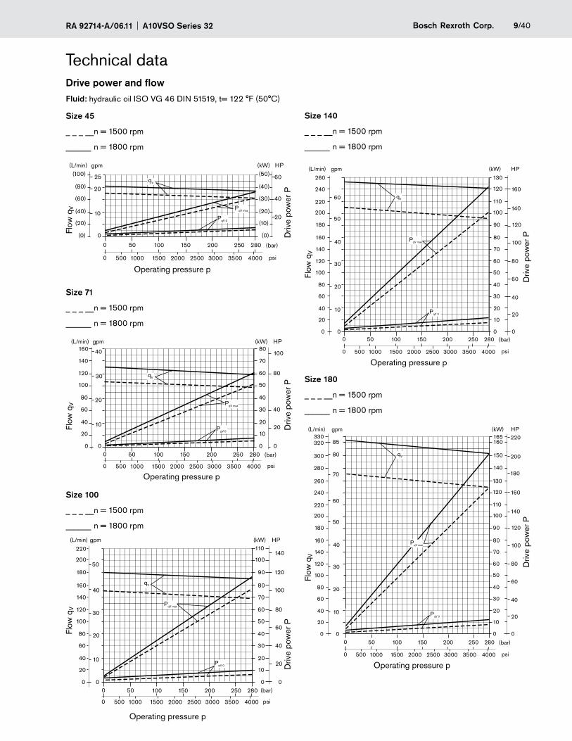
Technical dataDrive power and flowFluid: hydraulic oil ISO VG 46 DIN 51519, t= 122 °F (50°C)
Size 71
_ _ _ __n = 1500 rpm
______ n = 1800 rpm
Size 45
_ _ _ __n = 1500 rpm
______ n = 1800 rpm
Size 100
_ _ _ __n = 1500 rpm
______ n = 1800 rpm
Size 140
_ _ _ __n = 1500 rpm
______ n = 1800 rpm
Size 180
_ _ _ __n = 1500 rpm
______ n = 1800 rpm
280
300
320330
gpm(L/min) HP(kW)
140
150
160165
180
200
220
qV
PqV max
PqV 0
(bar)
psi
0 50 100 150 200 250 280
0 500 1000 1500 2000 2500 3000 3500 4000
200
220
240
260
180
140
160
120
100
80
60
40
20
0
50
60
70
80
85
40
30
20
10
0
100
110
120
130
90
70
80
60
50
40
30
20
10
0
140
160
120
100
80
60
40
20
0
140
160(L/min) gpm
120
100
80
60
40
20
0
40
30
20
10
0
70
80
60
50
40
30
20
10
0
100
80
40
20
0
qV
PqV max
PqV 0
(kW) HP
(bar)
psi
0 50 100 150 200 250 280
0 500 1000 1500 2000 2500 3000 3500 4000
200
220
180
140
160
120
100
80
60
40
20
0
50
(L/min) gpm (kW) HP
40
30
20
10
0
100
110
90
70
80
60
50
40
30
20
10
0
140
120
100
80
60
40
20
00 50 100 150 200 250 280
PqV max
PqV 0
qV
(bar)
psi0 500 1000 1500 2000 2500 3000 3500 4000
200
220
240
260
180
140
160
120
100
80
60
40
20
0
50
60
(L/min) gpm (kW) HP
40
30
20
10
0
100
110
120
130
90
70
80
60
50
40
30
20
10
0
140
160
120
100
80
60
40
20
0
qV
PqV max
PqV 0
(bar)
psi
0 50 100 150 200 250 280
0 500 1000 1500 2000 2500 3000 3500 4000
(100)
(80)
(60)
(40)
(20)
(0)
25
(L/min) gpm (kW)
(bar)
psi
HP
20
10
0
(50)
(40)
(30) 40
60
20(20)
(10)
(0)
0 50 100 150 200 250 280
0 500 1000 1500 2000 2500 3000 3500 4000
qV
PqV max
PqV 0
Operating pressure p
Operating pressure p
Operating pressure p
Flow
qV
Flow
qV
Flow
qV
Driv
e po
wer
PD
rive
pow
er PD
rive
pow
er P
Driv
e po
wer
PD
rive
pow
er P
Flow
qV
Flow
qV
Operating pressure p
Operating pressure p
A10VSO Series 32 RA 92714-A/06.1110/40 Bosch Rexroth Corp.
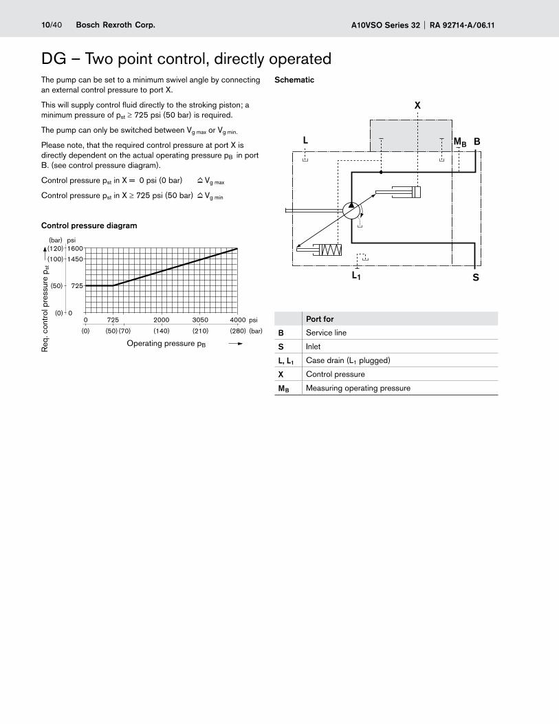
DG – Two point control, directly operatedThe pump can be set to a minimum swivel angle by connecting an external control pressure to port X.
This will supply control fluid directly to the stroking piston; a minimum pressure of pst ≥ 725 psi (50 bar) is required.
The pump can only be switched between Vg max or Vg min.
Please note, that the required control pressure at port X is directly dependent on the actual operating pressure pB in port B. (see control pressure diagram).
Control pressure pst in X = 0 psi (0 bar) Vg max
Control pressure pst in X ≥ 725 psi (50 bar) Vg min
Control pressure diagram
Schematic
Port for
B Service line
S Inlet
L, L1 Case drain (L1 plugged)
X Control pressure
MB Measuring operating pressure
X
L BMB
SL1
(0) (280)(50) (70) (140) (210)
0(0) 0
4000
(bar)
psi725 2000 3050
1600
1450
725
(120)psi(bar)
(100)
(50)
Req
. con
trol
pre
ssur
e p s
t
Operating pressure pB
11/40Bosch Rexroth Corp.RA 92714-A/06.11 A10VSO Series 32
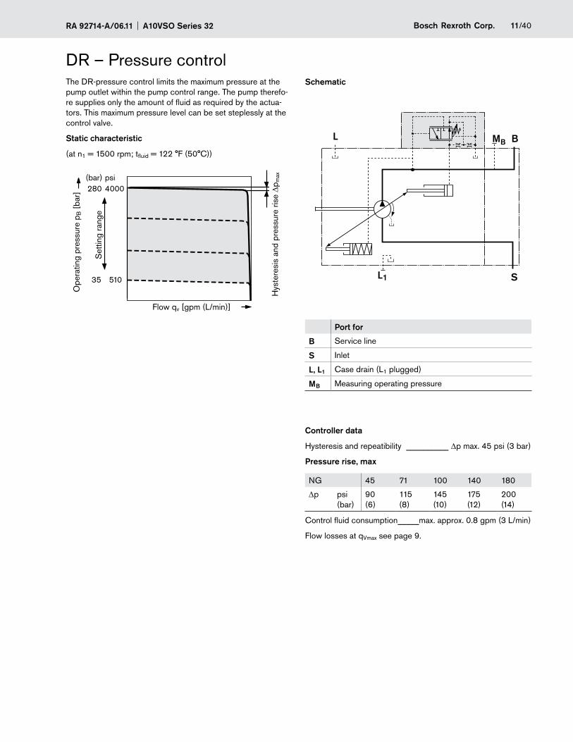
DR – Pressure controlThe DR-pressure control limits the maximum pressure at the pump outlet within the pump control range. The pump therefo-re supplies only the amount of fluid as required by the actua-tors. This maximum pressure level can be set steplessly at the control valve.
Static characteristic
(at n1 = 1500 rpm; tfluid = 122 °F (50°C))
Schematic
Port for
B Service line
S Inlet
L, L1 Case drain (L1 plugged)
MB Measuring operating pressure
Controller data
Hysteresis and repeatibility __________ Dp max. 45 psi (3 bar)
Pressure rise, max
NG 45 71 100 140 180
Dp psi (bar)
90 (6)
115 (8)
145 (10)
175 (12)
200 (14)
Control fluid consumption _____max. approx. 0.8 gpm (3 L/min)
Flow losses at qVmax see page 9.
L BMB
SL1510
4000
35
280psi(bar)
Flow qv [gpm (L/min)]
Ope
ratin
g pr
essu
re p
B [
bar]
Hys
tere
sis
and
pres
sure
rise
Dp m
ax
Set
ting
rang
e
A10VSO Series 32 RA 92714-A/06.1112/40 Bosch Rexroth Corp.
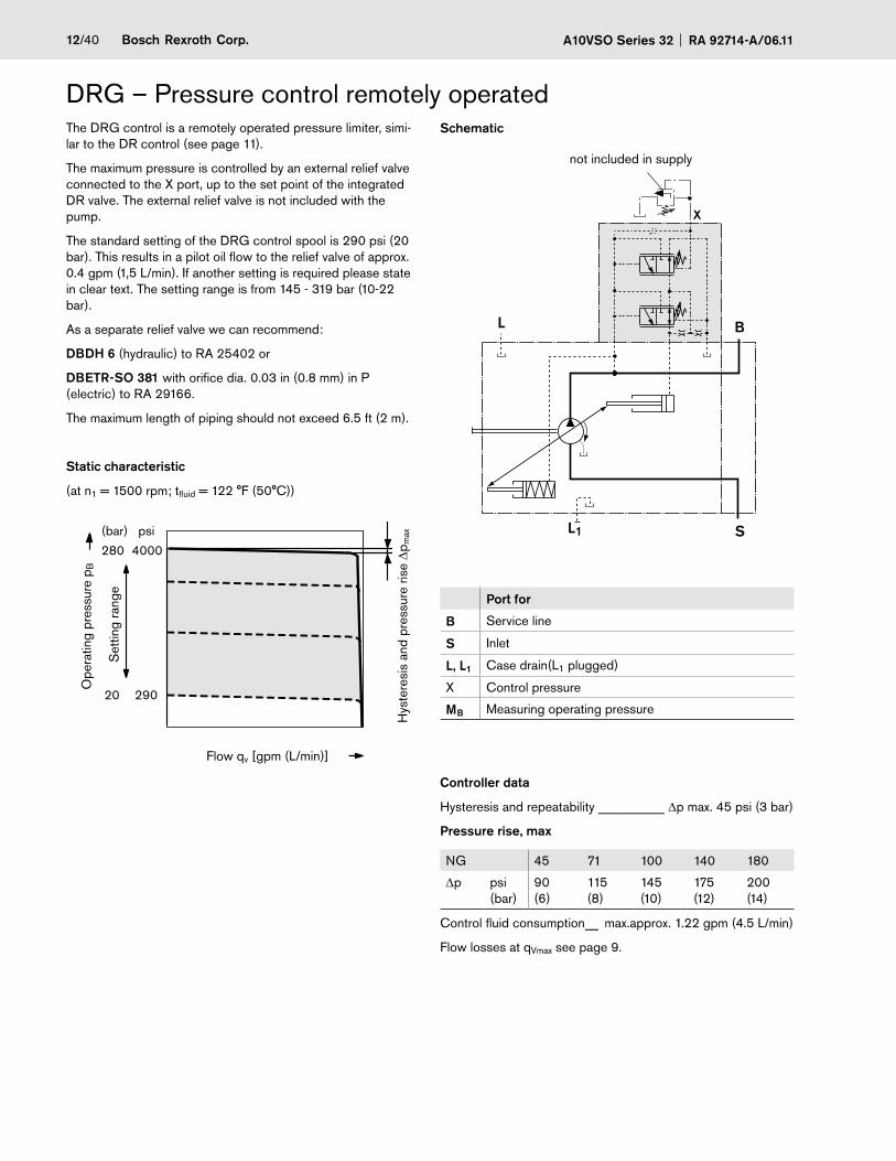
The DRG control is a remotely operated pressure limiter, simi-lar to the DR control (see page 11).
The maximum pressure is controlled by an external relief valve connected to the X port, up to the set point of the integrated DR valve. The external relief valve is not included with the pump.
The standard setting of the DRG control spool is 290 psi (20 bar). This results in a pilot oil flow to the relief valve of approx. 0.4 gpm (1,5 L/min). If another setting is required please state in clear text. The setting range is from 145 - 319 bar (10-22 bar).
As a separate relief valve we can recommend:
DBDH 6 (hydraulic) to RA 25402 or
DBETR-SO 381 with orifice dia. 0.03 in (0.8 mm) in P (electric) to RA 29166.
The maximum length of piping should not exceed 6.5 ft (2 m).
Static characteristic
(at n1 = 1500 rpm; tfluid = 122 °F (50°C))
DRG – Pressure control remotely operatedSchematic
Port for
B Service line
S Inlet
L, L1 Case drain(L1 plugged)
X Control pressure
MB Measuring operating pressure
Controller data
Hysteresis and repeatability __________ Dp max. 45 psi (3 bar)
Pressure rise, max
NG 45 71 100 140 180
Dp psi (bar)
90 (6)
115 (8)
145 (10)
175 (12)
200 (14)
Control fluid consumption __ max.approx. 1.22 gpm (4.5 L/min)
Flow losses at qVmax see page 9.
L B
SL1
X
290
4000
20
280
psi(bar)
Flow qv [gpm (L/min)]
Ope
ratin
g pr
essu
re p
B
Hys
tere
sis
and
pres
sure
rise
Dp m
ax
Set
ting
rang
e
not included in supply
13/40Bosch Rexroth Corp.RA 92714-A/06.11 A10VSO Series 32
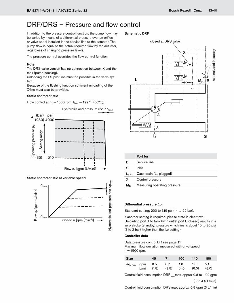
DRF/DRS – Pressure and flow controlSchematic DRF
Port for
B Service line
S Inlet
L, L1 Case drain (L1 plugged)
X Control pressure
MB Measuring operating pressure
Differential pressure Dp:
Standard setting: 200 to 319 psi (14 to 22 bar).
If another setting is required, please state in clear text. Unloading port X to tank (with outlet port B closed) results in a zero stroke (standby) pressure which lies is about 15 to 30 psi (1 to 2 bar) higher than the Dp setting).
Controller data
Data pressure control DR see page 11. Maximum flow deviation measured with drive speed n = 1500 rpm.
Size 45 71 100 140 180
Dqv max gpm L/min
0.5 (1.8)
0.7 (2.8)
1.0 (4.0)
1.6 (6.0)
2.1 (8.0)
Control fluid consumption DRF __ max. approx.0.8 to 1.22 gpm
(3 to 4.5 L/min)
Control fluid consumption DRS max. approx. 0.8 gpm (3 L/min)
In additon to the pressure control function, the pump flow may be varied by means of a differential pressure over an orifice or valve spool installed in the service line to the actuator. The pump flow is equal to the actual required flow by the actuator, regardless of changing pressure levels.
The pressure control overrides the flow control function.
Note The DRS-valve version has no connection between X and the tank (pump housing). Unloading the LS-pilot line must be possible in the valve sys-tem. Because of the flushing function sufficient unloading of the X-line must also be provided.
Static characteristic
Flow control at n1 = 1500 rpm; tfluid = 122 °F (50°C))
Static characteristic at variable speed
510
4000
(35)
(280)psi(bar)
X
L BMB
SL1
qV max
qV min
Flow qv [gpm (L/min)]
Flow
qv [
gpm
(L/
min
)]O
pera
ting
pres
sure
pB
Hysteresis and pressure rise DpmaxH
yste
resi
s an
d pr
essu
re ri
se D
p max
Set
ting
rang
eclosed at DRS valve
not i
nclu
ded
in s
uppl
y
Speed n [rpm (min-1)]
A10VSO Series 32 RA 92714-A/06.1114/40 Bosch Rexroth Corp.
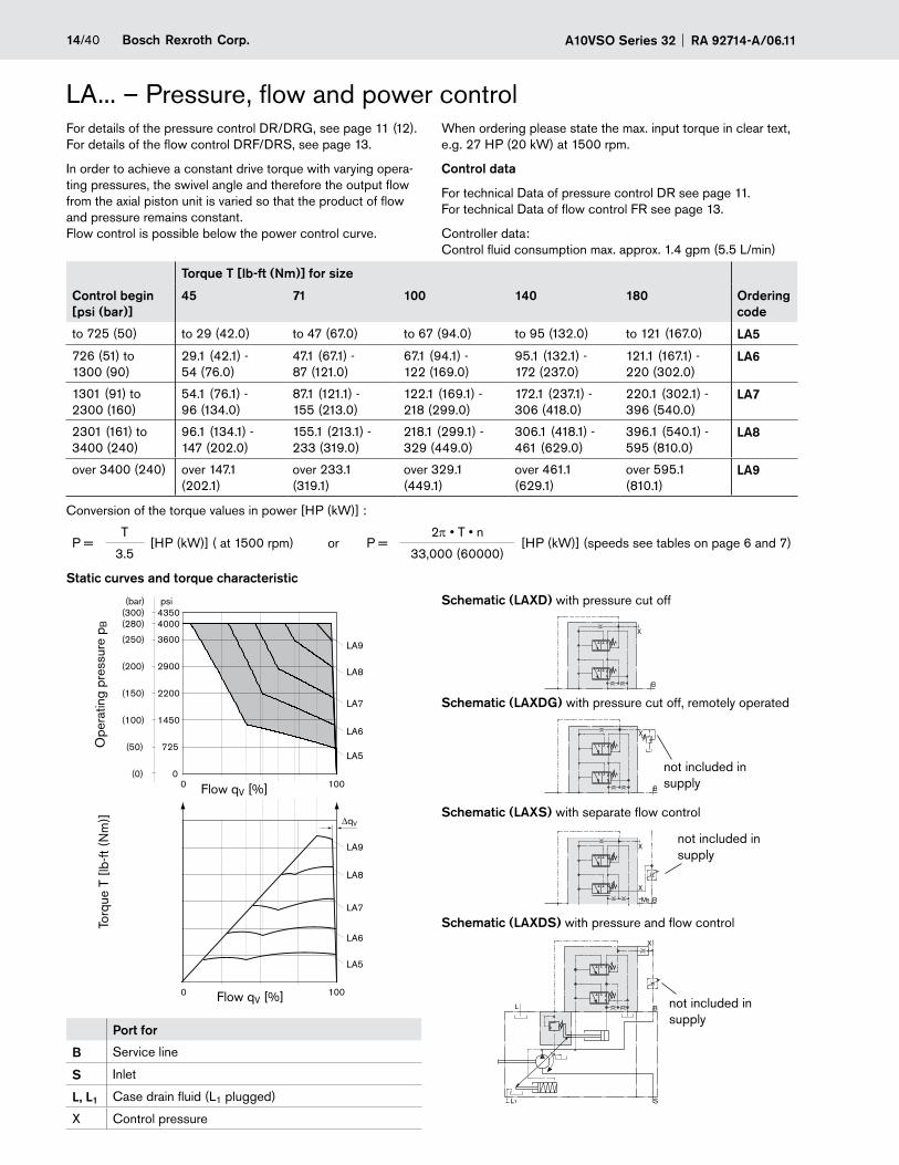
LA... – Pressure, flow and power controlFor details of the pressure control DR/DRG, see page 11 (12). For details of the flow control DRF/DRS, see page 13.
In order to achieve a constant drive torque with varying opera-ting pressures, the swivel angle and therefore the output flow from the axial piston unit is varied so that the product of flow and pressure remains constant. Flow control is possible below the power control curve.
Schematic (LAXDS) with pressure and flow control
When ordering please state the max. input torque in clear text, e.g. 27 HP (20 kW) at 1500 rpm.
Control data
For technical Data of pressure control DR see page 11. For technical Data of flow control FR see page 13.
Controller data: Control fluid consumption max. approx. 1.4 gpm (5.5 L/min)
Schematic (LAXS) with separate flow control
Schematic (LAXDG) with pressure cut off, remotely operated
Torque T [lb-ft (Nm)] for size
Control begin [psi (bar)]
45 71 100 140 180 Ordering code
to 725 (50) to 29 (42.0) to 47 (67.0) to 67 (94.0) to 95 (132.0) to 121 (167.0) LA5
726 (51) to 1300 (90)
29.1 (42.1) - 54 (76.0)
47.1 (67.1) - 87 (121.0)
67.1 (94.1) - 122 (169.0)
95.1 (132.1) - 172 (237.0)
121.1 (167.1) - 220 (302.0)
LA6
1301 (91) to 2300 (160)
54.1 (76.1) - 96 (134.0)
87.1 (121.1) - 155 (213.0)
122.1 (169.1) - 218 (299.0)
172.1 (237.1) - 306 (418.0)
220.1 (302.1) - 396 (540.0)
LA7
2301 (161) to 3400 (240)
96.1 (134.1) - 147 (202.0)
155.1 (213.1) - 233 (319.0)
218.1 (299.1) - 329 (449.0)
306.1 (418.1) - 461 (629.0)
396.1 (540.1) - 595 (810.0)
LA8
over 3400 (240) over 147.1 (202.1)
over 233.1 (319.1)
over 329.1 (449.1)
over 461.1 (629.1)
over 595.1 (810.1)
LA9
Conversion of the torque values in power [HP (kW)] :
P =T
[HP (kW)] ( at 1500 rpm) or P =2p • T • n
[HP (kW)] (speeds see tables on page 6 and 7)3.5 33,000 (60000)
Static curves and torque characteristic
Schematic (LAXD) with pressure cut off
Port for
B Service line
S Inlet
L, L1 Case drain fluid (L1 plugged)
X Control pressure
0 100
0
725
1450
2200
2900
3600
40004350
(0)
(50)
(100)
(150)
(200)
(250)
(280)(300)
psi(bar)
0 100
∆qV
LA9
LA8
LA7
LA5
LA6
LA9
LA8
LA7
LA5
LA6X
B
S
L
1L
X
BBM
X
X
B
X
B
Ope
ratin
g pr
essu
re p
B
Flow qV [%]
Torq
ue T
[lb
-ft (
Nm
)]
not included in supply
not included in supply
not included in supply
Flow qV [%]
15/40Bosch Rexroth Corp.RA 92714-A/06.11 A10VSO Series 32
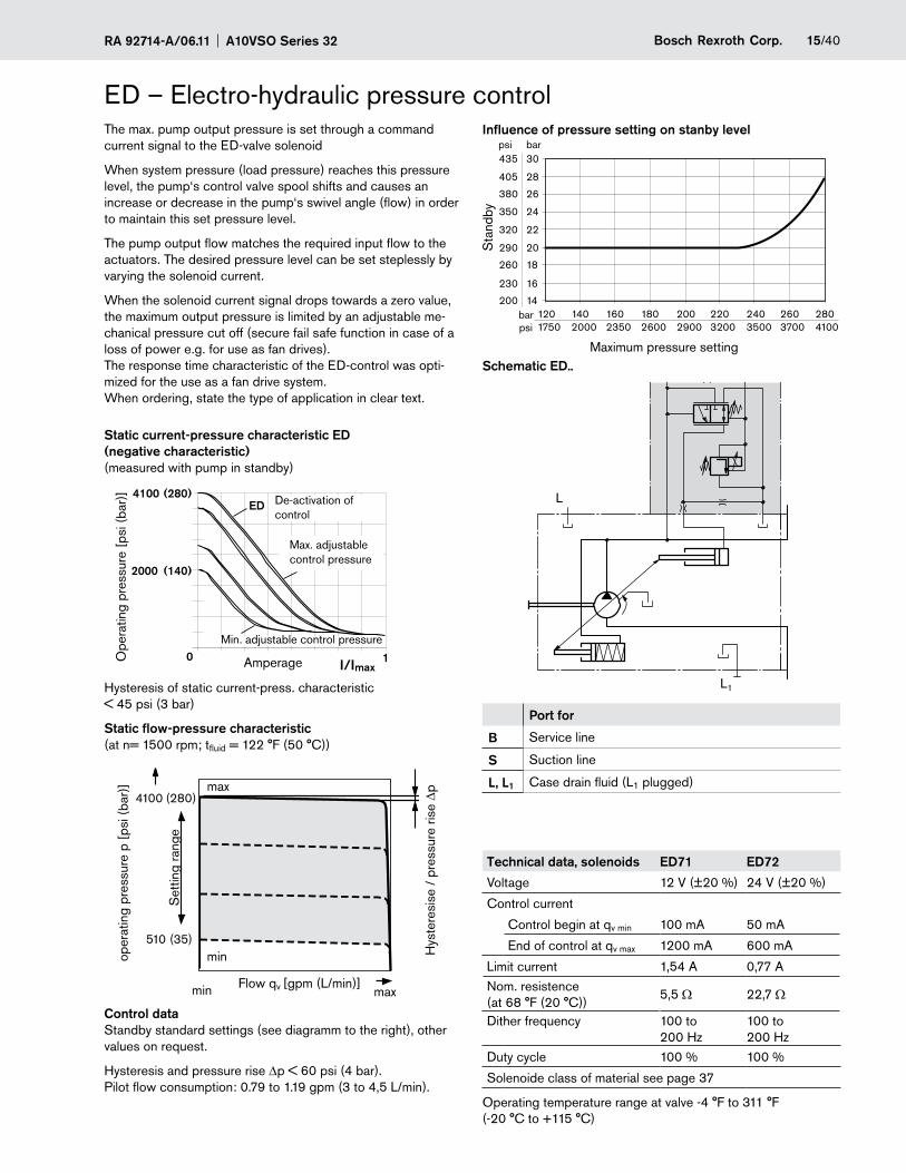
ED – Electro-hydraulic pressure controlThe max. pump output pressure is set through a command current signal to the ED-valve solenoid
When system pressure (load pressure) reaches this pressure level, the pump‘s control valve spool shifts and causes an increase or decrease in the pump‘s swivel angle (flow) in order to maintain this set pressure level.
The pump output flow matches the required input flow to the actuators. The desired pressure level can be set steplessly by varying the solenoid current.
When the solenoid current signal drops towards a zero value, the maximum output pressure is limited by an adjustable me-chanical pressure cut off (secure fail safe function in case of a loss of power e.g. for use as fan drives). The response time characteristic of the ED-control was opti-mized for the use as a fan drive system. When ordering, state the type of application in clear text.
Static current-pressure characteristic ED (negative characteristic)(measured with pump in standby)
Hysteresis of static current-press. characteristic < 45 psi (3 bar)
Static flow-pressure characteristic(at n= 1500 rpm; tfluid = 122 °F (50 °C))
Control dataStandby standard settings (see diagramm to the right), other values on request.
Hysteresis and pressure rise Dp < 60 psi (4 bar). Pilot flow consumption: 0.79 to 1.19 gpm (3 to 4,5 L/min).
Influence of pressure setting on stanby level
Schematic ED..
Port for
B Service line
S Suction line
L, L1 Case drain fluid (L1 plugged)
Technical data, solenoids ED71 ED72
Voltage 12 V (±20 %) 24 V (±20 %)
Control current
Control begin at qv min 100 mA 50 mA
End of control at qv max 1200 mA 600 mA
Limit current 1,54 A 0,77 ANom. resistence (at 68 °F (20 °C))
5,5 Ω 22,7 Ω
Dither frequency 100 to 200 Hz
100 to 200 Hz
Duty cycle 100 % 100 %
Solenoide class of material see page 37
Operating temperature range at valve -4 °F to 311 °F (-20 °C to +115 °C)
(35)
(280)
510
4100
(280)
0I/Imax
1
ED
(140)
4100
2000
B
SL1
L
30
28
26
24
22
20
18
16
14
435bar
bar
psi
psi
405
380
350
320
290
260
230
200120 140 160 180 200 220 240 260 2801750 2000 2350 2600 2900 3200 3500 3700 4100
max
min
maxmin
Ope
ratin
g pr
essu
re [
psi (
bar)
]
Amperage
De-activation of control
Max. adjustable control pressure
Min. adjustable control pressure
Hys
tere
sise
/ p
ress
ure
rise Dp
Flow qv [gpm (L/min)]
oper
atin
g pr
essu
re p
[ps
i (ba
r)]
Set
ting
rang
e
Sta
ndby
Maximum pressure setting
A10VSO Series 32 RA 92714-A/06.1116/40 Bosch Rexroth Corp.
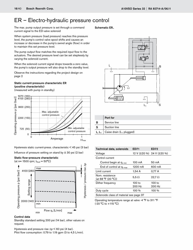
The max. pump output pressure is set through a command current signal to the ED-valve solenoid
When system pressure (load pressure) reaches this pressure level, the pump‘s control valve spool shifts and causes an increase or decrease in the pump‘s swivel angle (flow) in order to maintain this set pressure level.
The pump output flow matches the required input flow to the actuators. The desired pressure level can be set steplessly by varying the solenoid current.
When the solenoid current signal drops towards a zero value, the pump‘s output pressure will also drop to the standby level.
Observe the instructions regarding the project design on page 2
Static current-pressure characteristic ER (positive characteristic)(measured with pump in standby)
Hysteresis static current-press. characteristic < 45 psi (3 bar)
Influence of pressure setting on stand by ± 30 psi (2 bar)
Static flow-pressure characteristic(at n= 1500 rpm; tfluid = 50°C)
Control dataStandby standard setting 200 psi (14 bar), other values on request.
Hysteresis and pressure rise Dp < 60 psi (4 bar). Pilot flow consumption: 0.79 to 1.19 gpm (3 to 4,5 L/min).
Schematic ER..
Port for
B Service line
S Suction line
L, L1 Caise drain (L1 plugged)
Technical data, solenoids ED71 ED72
Voltage 12 V (±20 %) 24 V (±20 %)
Control current
Control begin at qv min 100 mA 50 mA
End of control at qv max 1200 mA 600 mA
Limit current 1,54 A 0,77 ANom. resistence (at 68 °F (20 °C))
5,5 Ω 22,7 Ω
Dither frequency 100 to 200 Hz
100 to 200 Hz
Duty cycle 100 % 100 %
Solenoide class of material see page 37
Operating temperature range at valve -4 °F to 311 °F (-20 °C to +115 °C)
ER – Electro-hydraulic pressure control
(140)
(280)
2000
4100
0 10
(50)
(150)
(250)
(350)
725
2200
3600
(280)41005070
I/Imax
B
SL1
L
Ope
ratin
g pr
essu
re p
[ps
i (ba
r)]
Amperage
Max. adjustable control pressure
Min. adjustable control pressure
Hys
tere
sis
/ pr
essu
re ri
se D
p
Ope
ratin
g pr
essu
re p
[ps
i (ba
r)]
Set
ting
rang
e
max
min
Flow qv [L/min]maxmin
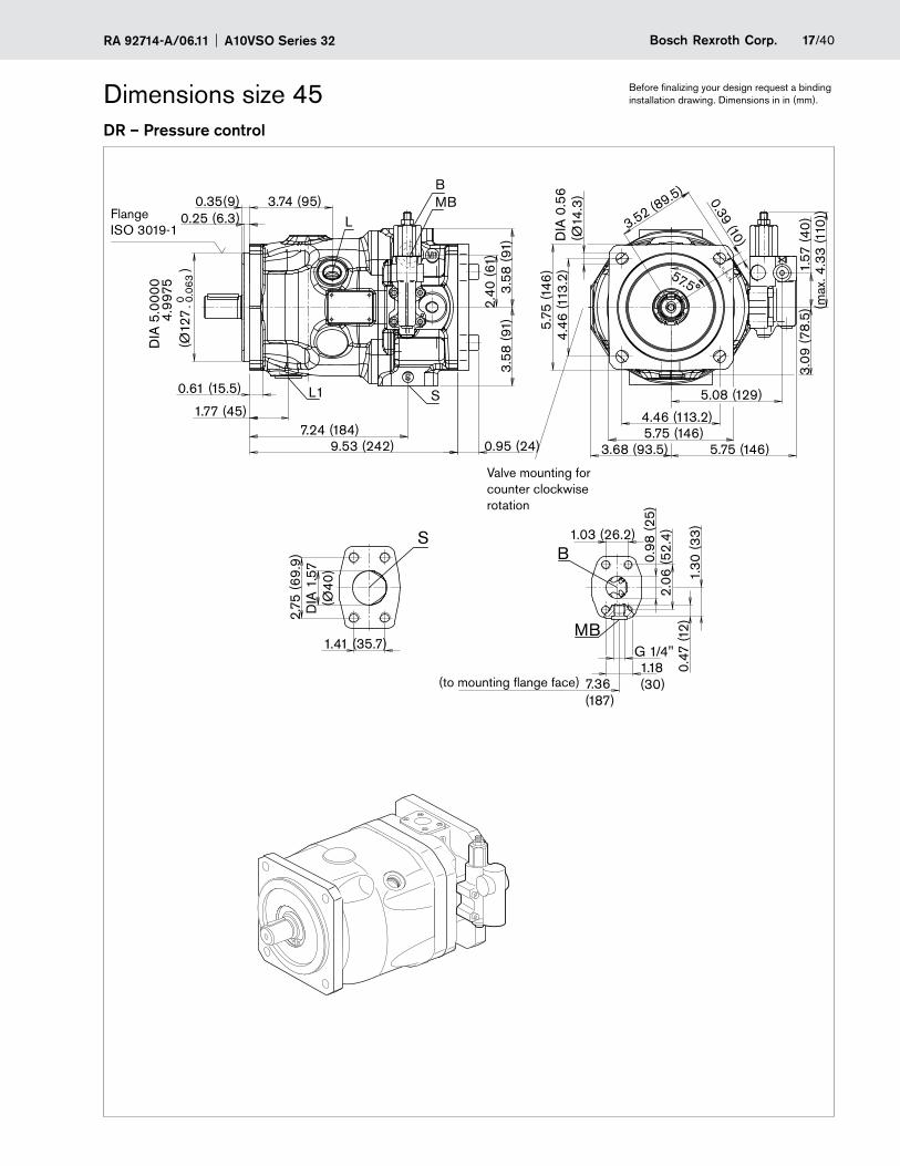
17/40Bosch Rexroth Corp.RA 92714-A/06.11 A10VSO Series 32
DR – Pressure control
Dimensions size 45 Before finalizing your design request a binding installation drawing. Dimensions in in (mm).
57.5°
0.98
(25)
2.06
(52.
4)
3.58
(91)
3.58
(91)
2.40
(61)
5.08 (129)
1.57
(40
)
1.41 (35.7)
2.75
(69.
9)
S
DIA
1.5
7(Ø
40)
MBB
L
L1 S
3.52 (89.5) 0.39 (10)D
IA 0
.56
(Ø14
.3)
(max
. 4.3
3 (1
10))
5.75 (146)
4.46 (113.2)5.75 (146)
4.46
(113
.2)
5.75
(146
)
(Ø12
7
)
DIA
5.0
000
4.99
750 - 0
.063
3.74 (95)
3.09
(78.
5)
3.68 (93.5)
0.35(9)0.25 (6.3)
7.24 (184)1.77 (45)
9.53 (242) 0.95 (24)
B
MBG 1/4"
7.36(187)
1.18(30)
1.03 (26.2)
0.61 (15.5)
X
0.47
(12)
1.30
(33
)
Flange ISO 3019-1
(to mounting flange face)
Valve mounting for counter clockwise rotation
A10VSO Series 32 RA 92714-A/06.1118/40 Bosch Rexroth Corp.
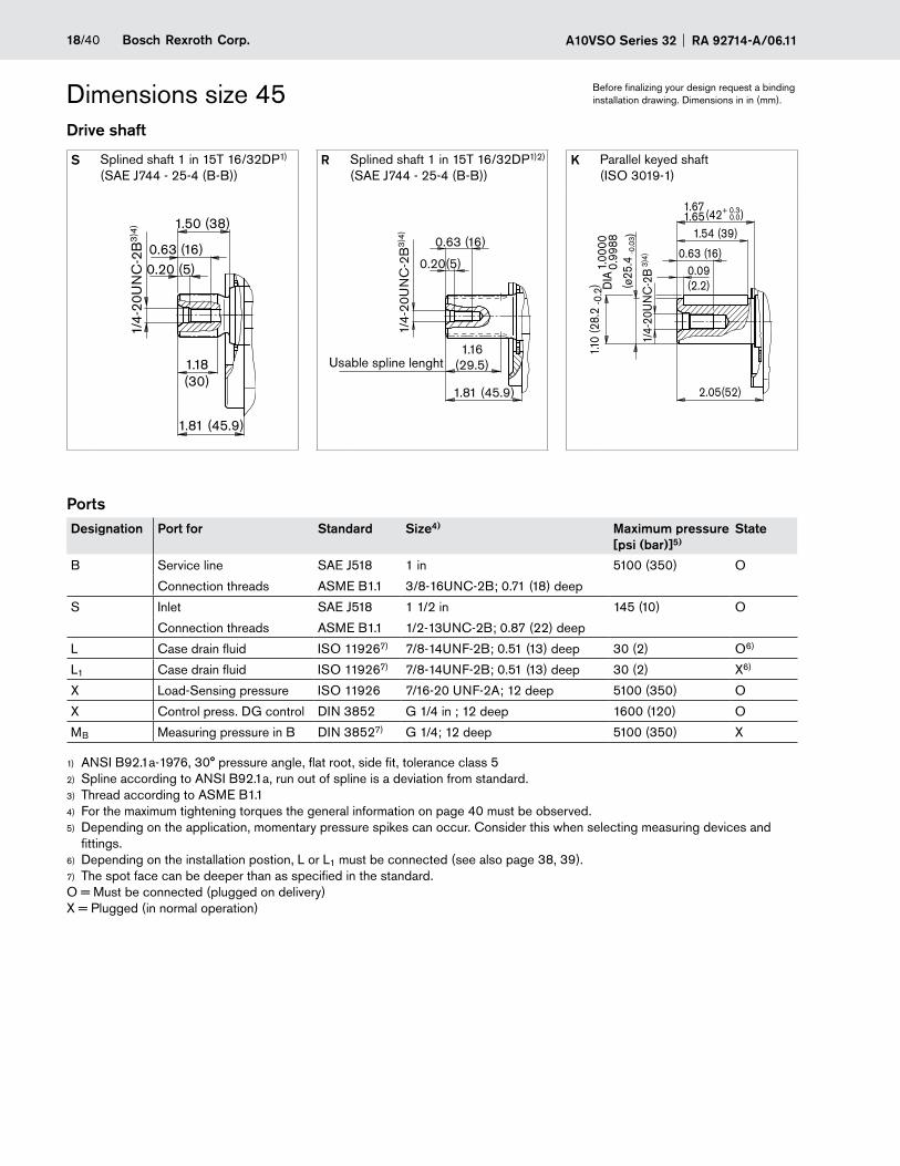
Before finalizing your design request a binding installation drawing. Dimensions in in (mm).Dimensions size 45
Drive shaft
S Splined shaft 1 in 15T 16/32DP1) (SAE J744 - 25-4 (B-B))
R Splined shaft 1 in 15T 16/32DP1)2) (SAE J744 - 25-4 (B-B))
K Parallel keyed shaft (ISO 3019-1)
PortsDesignation Port for Standard Size4) Maximum pressure
[psi (bar)]5)State
B Service line SAE J518 1 in 5100 (350) O
Connection threads ASME B1.1 3/8-16UNC-2B; 0.71 (18) deep
S Inlet SAE J518 1 1/2 in 145 (10) O
Connection threads ASME B1.1 1/2-13UNC-2B; 0.87 (22) deep
L Case drain fluid ISO 119267) 7/8-14UNF-2B; 0.51 (13) deep 30 (2) O6)
L1 Case drain fluid ISO 119267) 7/8-14UNF-2B; 0.51 (13) deep 30 (2) X6)
X Load-Sensing pressure ISO 11926 7/16-20 UNF-2A; 12 deep 5100 (350) O
X Control press. DG control DIN 3852 G 1/4 in ; 12 deep 1600 (120) O
MB Measuring pressure in B DIN 38527) G 1/4; 12 deep 5100 (350) X
ANSI B92.1a-1976, 30° pressure angle, flat root, side fit, tolerance class 51)
Spline2) according to ANSI B92.1a, run out of spline is a deviation from standard.Thread according to ASME B1.13)
For the maximum tightening torques the general information on page 40 must be observed.4)
Depending on the application, momentary pressure spikes can occur. Consider this when selecting measuring devices and 5)
fittings.Depending on the installation postion, L or L6) 1 must be connected (see also page 38, 39).The spot face can be deeper than as specified in the standard.7)
O = Must be connected (plugged on delivery) X = Plugged (in normal operation)
1.81 (45.9)
0.63 (16)0.20 (5)
1.50 (38)
1.18(30)
1/4-
20U
NC
-2B
3)4
)
1.00
000.
9988
(ø25
.4 -0
.03)
1/4-
20U
NC
-2B
3)4
)
1.10
(28.
2 -0
.2)
2.05(52)
0.09(2.2)
0.63 (16)
(42 )+ 0.30.0
1.54 (39)
1.671.65
DIA
1/4-
20U
NC
-2B
3)4
)
0.63 (16)
1.81 (45.9)
1.16(29.5)
0.20(5)
Usable spline lenght
19/40Bosch Rexroth Corp.RA 92714-A/06.11 A10VSO Series 32
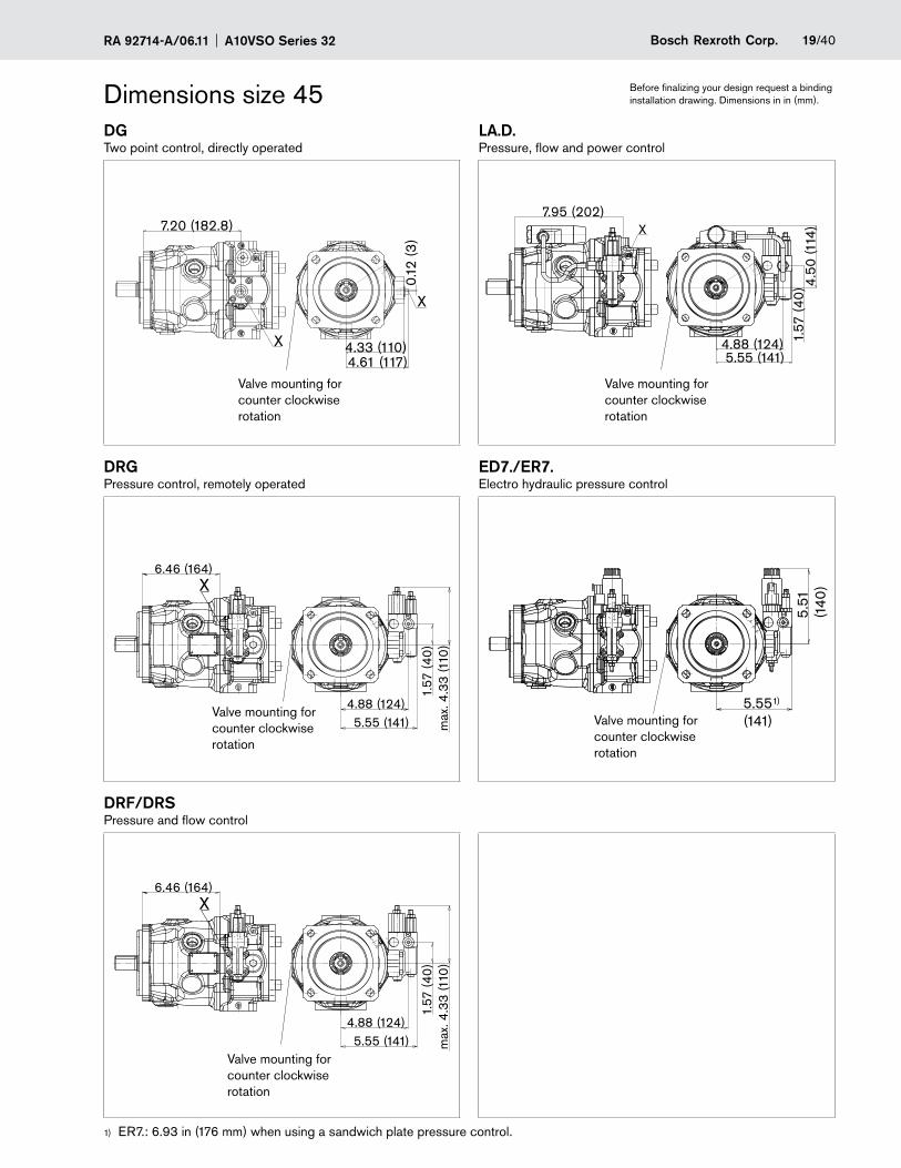
Before finalizing your design request a binding installation drawing. Dimensions in in (mm).Dimensions size 45
DGTwo point control, directly operated
LA.D.Pressure, flow and power control
DRGPressure control, remotely operated
ED7./ER7.Electro hydraulic pressure control
DRF/DRSPressure and flow control
ER7.: 6.93 in (176 mm) when using a sandwich plate pressure control.1)
6.46 (164)
4.88 (124)
1.57
(40
)
X
max
. 4.3
3 (1
10)
5.55 (141)
X
6.46 (164)
4.88 (124)
1.57
(40
)
X
max
. 4.3
3 (1
10)
5.55 (141)
X
X
X
7.20 (182.8)
4.33 (110)4.61 (117)
0.12
(3)
1.57
(40
) 4.50
(114
)
4.88 (124)5.55 (141)
7.95 (202)
X
X
5.51
(140
)
5.551)
(141)
X
Valve mounting for counter clockwise rotation
Valve mounting for counter clockwise rotation
Valve mounting for counter clockwise rotation
Valve mounting for counter clockwise rotation
Valve mounting for counter clockwise rotation
A10VSO Series 32 RA 92714-A/06.1120/40 Bosch Rexroth Corp.
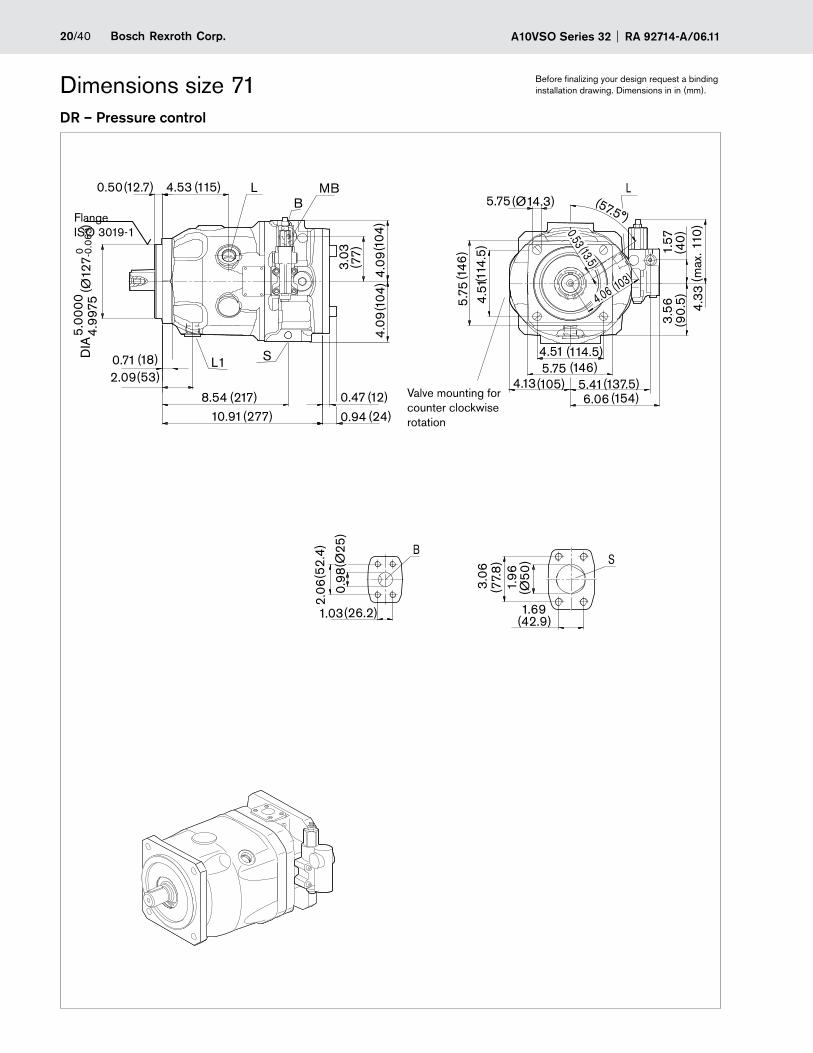
Before finalizing your design request a binding installation drawing. Dimensions in in (mm).
DR – Pressure control
Dimensions size 71
(146)5.75
(57.5°)(Ø14.3)5.75
(146
)5.
75(1
14.5
)4.
51
(90.
5)3.
56(4
0)
1.57
(154)6.06(137.5)5.41
(114.5)4.51
(105)4.13
(max
. 110
)4.
33
(18)0.71(53)2.09
(217)8.54
(12.7)0.50 (115)4.53
(104
)4.
09(1
04)
4.09
(12)0.47(24)0.94(277)10.91
(77)
3.03
MB
(52.
4)2.
06
(Ø25
)0.
98
(26.2)1.03
B
0.53 (13.5)
(103)
4.06
-0.0
634.
9975
(Ø12
7
)
5.00
000
DIA
(77.
8)
3.06
(Ø50
)1.
96
(42.9)1.69
S
L L
L1 S
BFlange ISO 3019-1
Valve mounting for counter clockwise rotation
21/40Bosch Rexroth Corp.RA 92714-A/06.11 A10VSO Series 32
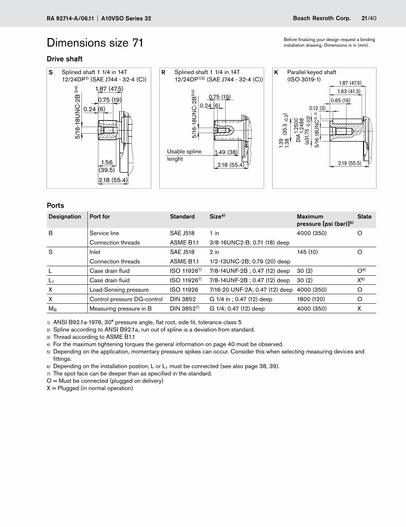
Before finalizing your design request a binding installation drawing. Dimensions in in (mm).Dimensions size 71
Drive shaft
S Splined shaft 1 1/4 in 14T 12/24DP1) (SAE J744 - 32-4 (C))
R Splined shaft 1 1/4 in 14T 12/24DP1)2) (SAE J744 - 32-4 (C))
K Parallel keyed shaft (ISO 3019-1)
PortsDesignation Port for Standard Size4) Maximum
pressure [psi (bar)]5)State
B Service line SAE J518 1 in 4000 (350) O
Connection threads ASME B1.1 3/8-16UNC2-B; 0.71 (18) deep
S Inlet SAE J518 2 in 145 (10) O
Connection threads ASME B1.1 1/2-13UNC-2B; 0.79 (20) deep
L Case drain fluid ISO 119267) 7/8-14UNF-2B ; 0.47 (12) deep 30 (2) O6)
L1 Case drain fluid ISO 119267) 7/8-14UNF-2B ; 0.47 (12) deep 30 (2) X6)
X Load-Sensing pressure ISO 11926 7/16-20 UNF-2A; 0.47 (12) deep 4000 (350) O
X Control pressure DG-control DIN 3852 G 1/4 in ; 0.47 (12) deep 1800 (120) O
MB Measuring pressure in B DIN 38527) G 1/4; 0.47 (12) deep 4000 (350) X
ANSI B92.1a-1976, 30° pressure angle, flat root, side fit, tolerance class 51)
Spline2) according to ANSI B92.1a, run out of spline is a deviation from standard.Thread according to ASME B1.13)
For the maximum tightening torques the general information on page 40 must be observed.4)
Depending on the application, momentary pressure spikes can occur. Consider this when selecting measuring devices and 5)
fittings.Depending on the installation postion, L or L6) 1 must be connected (see also page 38, 39).The spot face can be deeper than as specified in the standard.7)
O = Must be connected (plugged on delivery) X = Plugged (in normal operation)
2.18 (55.4)
0.75 (19)0.24 (6)
1.87 (47.5)
1.56(39.5)
5/16
-18U
NC
-2B
3)4
)
5/16
-18U
NC
-2B
3)4
)
0.75 (19)0.24 (6)
2.18 (55.4)
1.49 (38)
(ø31
.75
-0.0
3)
DIA
1.25
001.
2488
5/16
-18U
NC
3), 4
)
(35.
3 -0
.2)
1.39
1.38
2.19 (55.5)
0.12 (3)0.65 (19)
1.87 (47.5)
1.63 (41.3)
Usable spline lenght
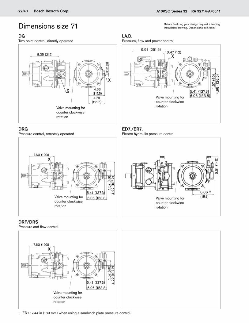
A10VSO Series 32 RA 92714-A/06.1122/40 Bosch Rexroth Corp.
Before finalizing your design request a binding installation drawing. Dimensions in in (mm).Dimensions size 71
DGTwo point control, directly operated
LA.D.Pressure, flow and power control
DRGPressure control, remotely operated
ED7./ER7.Electro hydraulic pressure control
DRF/DRSPressure and flow control
ER7.: 7.44 in (189 mm) when using a sandwich plate pressure control.1)
X7.60 (193)
1.57
(40
)4.
22 (1
07.2
)
5.41 (137.3)6.06 (153.8)
X7.60 (193)
1.57
(40
)4.
22 (1
07.2
)
5.41 (137.3)6.06 (153.8)
X
4.78(121.5)
0.12
(3)
4.63(117.5)
8.35 (212)
X
X9.91 (251.6)
0.47 (12)
4.98
(126
.5)
1.57
(40
)
5.41 (137.3)6.06 (153.8)
5.51
(140
)
6.06 1)
(154)
X
Valve mounting for counter clockwise rotation
Valve mounting for counter clockwise rotation
Valve mounting for counter clockwise rotation
Valve mounting for counter clockwise rotation
Valve mounting for counter clockwise rotation
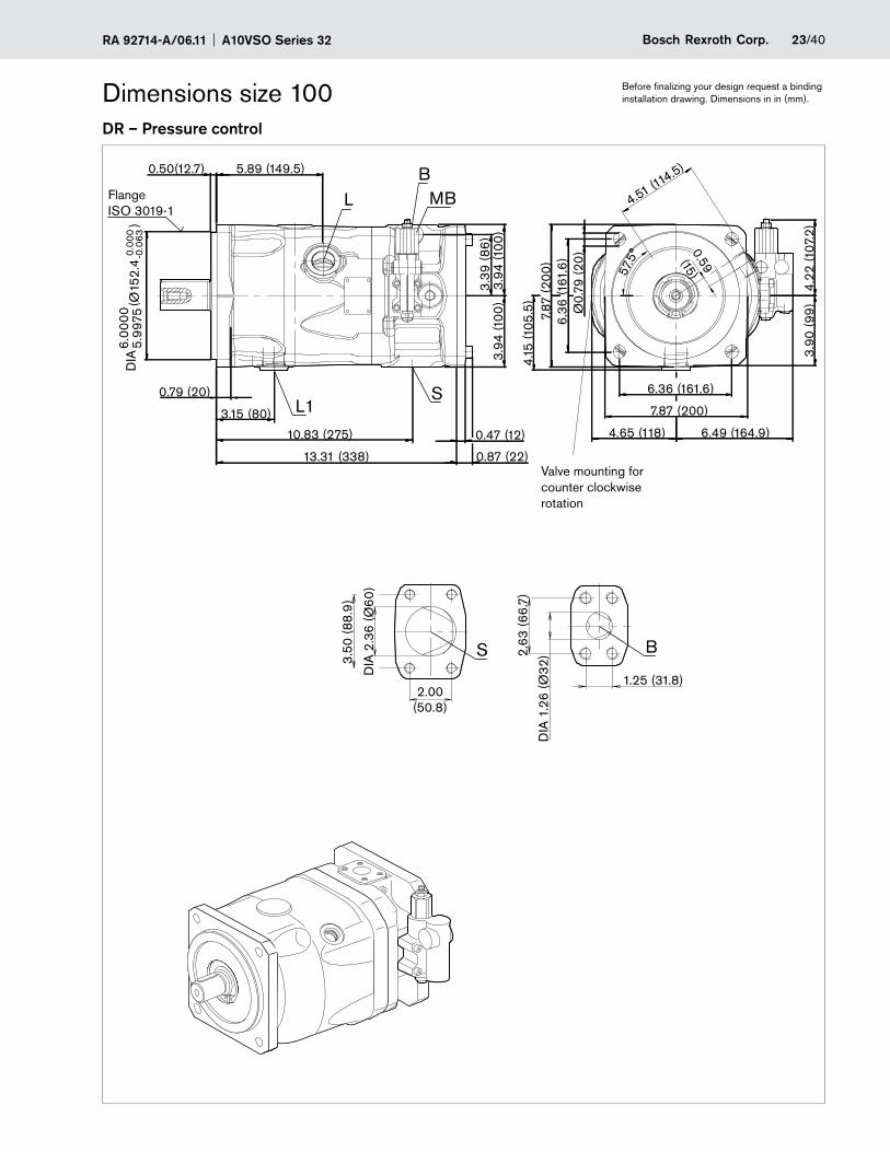
23/40Bosch Rexroth Corp.RA 92714-A/06.11 A10VSO Series 32
Before finalizing your design request a binding installation drawing. Dimensions in in (mm).
DR – Pressure control
Dimensions size 100
0.47 (12)
0.87 (22)
0.79 (20)
(Ø15
2.4
)6.
0000
5.99
75D
IA-0
.063
0.00
0
3.94
(100
)3.
94 (1
00)
3.39
(86
)
0.50(12.7) 5.89 (149.5)
13.31 (338)
3.15 (80)
10.83 (275)
L MBB
L1S
Ø0.
79 (2
0)
7.87 (200)
6.36 (161.6)
6.36
(161
.6)
4.15
(105
.5)
7.87
(200
)
4.22
(107
.2)
6.49 (164.9)
0.59(15)4.51 (11
4.5)
57.5
°
3.90
(99
)
4.65 (118)
DIA
1.2
6 (Ø
32)2.
63 (6
6.7)
1.25 (31.8)
3.50
(88.
9)
DIA
2.3
6 (Ø
60
)
2.00(50.8)
BS
Flange ISO 3019-1
Valve mounting for counter clockwise rotation
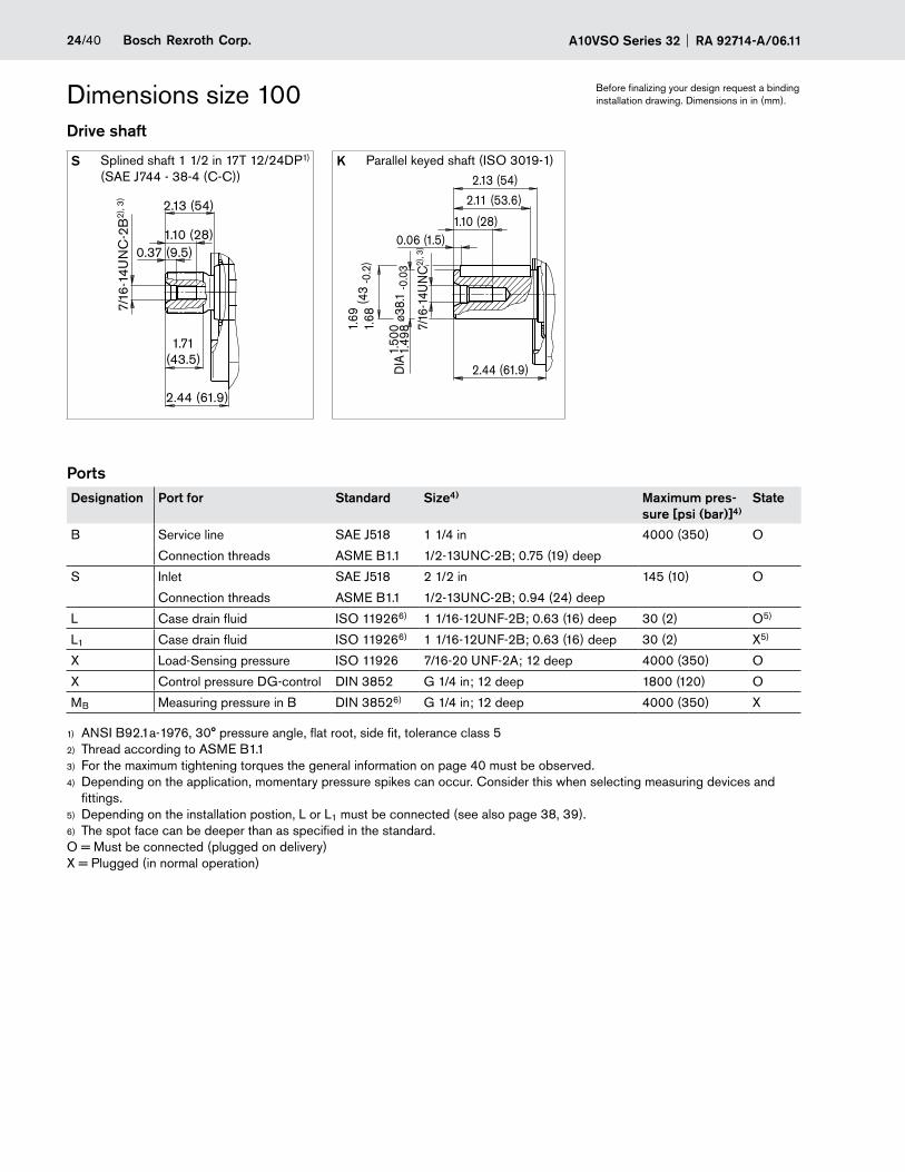
A10VSO Series 32 RA 92714-A/06.1124/40 Bosch Rexroth Corp.
Before finalizing your design request a binding installation drawing. Dimensions in in (mm).Dimensions size 100
Drive shaft
S Splined shaft 1 1/2 in 17T 12/24DP1) (SAE J744 - 38-4 (C-C))
K Parallel keyed shaft (ISO 3019-1)
PortsDesignation Port for Standard Size4) Maximum pres-
sure [psi (bar)]4)State
B Service line SAE J518 1 1/4 in 4000 (350) O
Connection threads ASME B1.1 1/2-13UNC-2B; 0.75 (19) deep
S Inlet SAE J518 2 1/2 in 145 (10) O
Connection threads ASME B1.1 1/2-13UNC-2B; 0.94 (24) deep
L Case drain fluid ISO 119266) 1 1/16-12UNF-2B; 0.63 (16) deep 30 (2) O5)
L1 Case drain fluid ISO 119266) 1 1/16-12UNF-2B; 0.63 (16) deep 30 (2) X5)
X Load-Sensing pressure ISO 11926 7/16-20 UNF-2A; 12 deep 4000 (350) O
X Control pressure DG-control DIN 3852 G 1/4 in; 12 deep 1800 (120) O
MB Measuring pressure in B DIN 38526) G 1/4 in; 12 deep 4000 (350) X
ANSI B92.1a-1976, 30° pressure angle, flat root, side fit, tolerance class 51)
Thread according to ASME B1.12)
For the maximum tightening torques the general information on page 40 must be observed.3)
Depending on the application, momentary pressure spikes can occur. Consider this when selecting measuring devices and 4)
fittings.Depending on the installation postion, L or L5) 1 must be connected (see also page 38, 39).The spot face can be deeper than as specified in the standard.6)
O = Must be connected (plugged on delivery) X = Plugged (in normal operation)
ø38.
1 -0
.03
1.50
01.
498
DIA
7/16
-14U
NC
2), 3
)
(43
-0.2
)2.44 (61.9)
0.06 (1.5)1.10 (28)
2.13 (54)
2.11 (53.6)
1.69
1.68
2.44 (61.9)
1.10 (28)0.37 (9.5)
2.13 (54)
1.71(43.5)
7/16
-14U
NC
-2B
2), 3
)
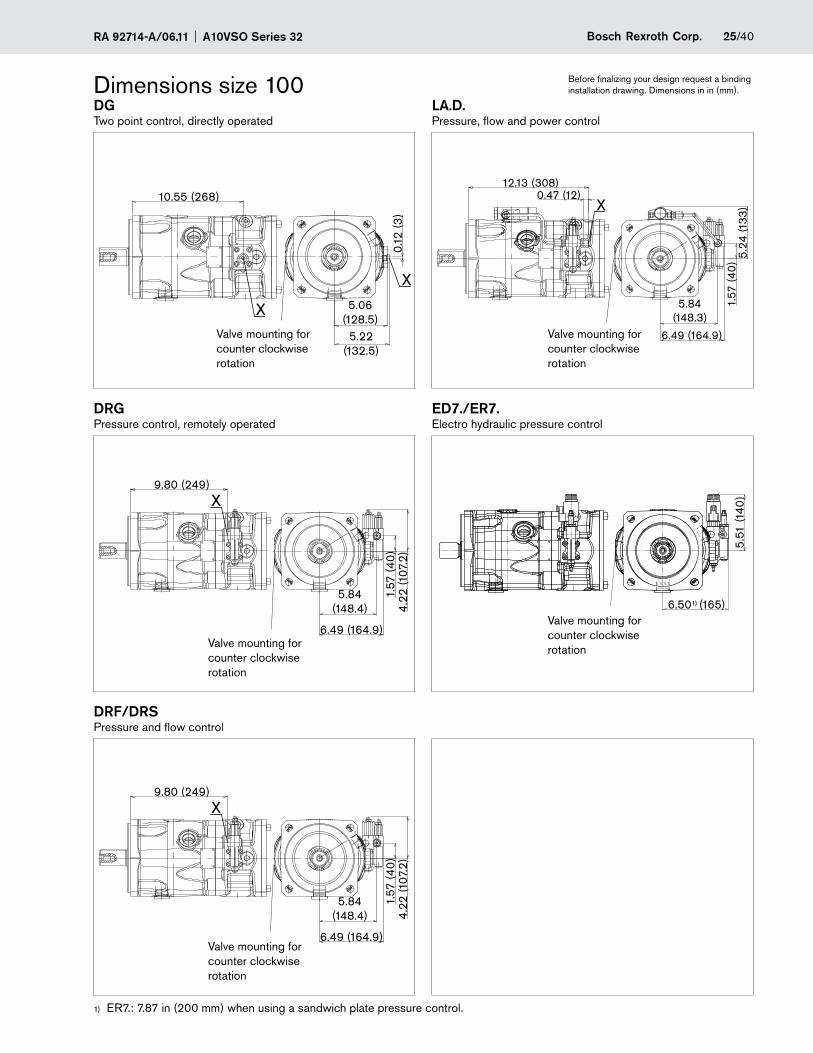
25/40Bosch Rexroth Corp.RA 92714-A/06.11 A10VSO Series 32
Before finalizing your design request a binding installation drawing. Dimensions in in (mm).Dimensions size 100
DGTwo point control, directly operated
LA.D.Pressure, flow and power control
DRGPressure control, remotely operated
ED7./ER7.Electro hydraulic pressure control
DRF/DRSPressure and flow control
ER7.: 7.87 in (200 mm) when using a sandwich plate pressure control.1)
0.12
(3)
5.22(132.5)
5.06(128.5)
10.55 (268)
X
X
X
6.49 (164.9)
1.57
(40
)4.
22 (1
07.2
)
5.84(148.4)
9.80 (249)
X
6.49 (164.9)
1.57
(40
)4.
22 (1
07.2
)
5.84(148.4)
9.80 (249)
1.57
(40
)
0.47 (12)12.13 (308)
5.24
(133
)
6.49 (164.9)
5.84(148.3)
X
5.51
(140
)
6.501) (165)
X
Valve mounting for counter clockwise rotation
Valve mounting for counter clockwise rotation
Valve mounting for counter clockwise rotationValve mounting for
counter clockwise rotation
Valve mounting for counter clockwise rotation
A10VSO Series 32 RA 92714-A/06.1126/40 Bosch Rexroth Corp.
Before finalizing your design request a binding installation drawing. Dimensions in in (mm).
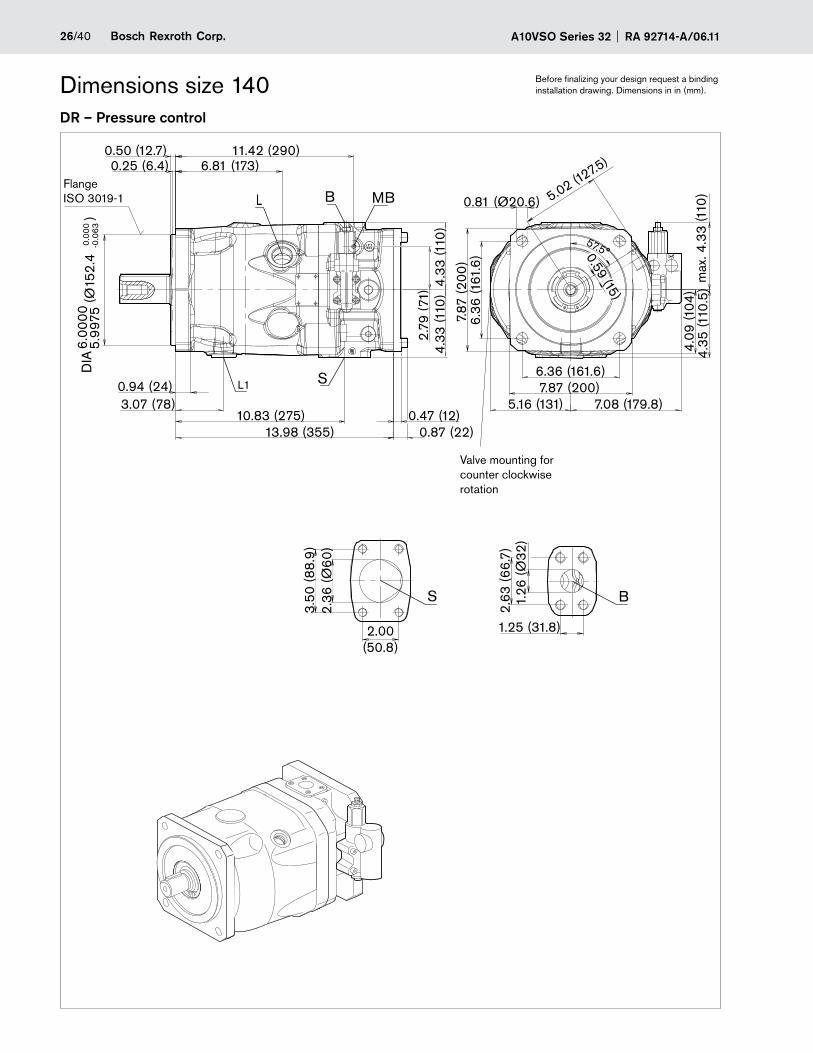
DR – Pressure control
Dimensions size 140
B MB
S
L
L1
X
11.42 (290)
5.02 (127.5)
0.47 (12)
max
. 4.3
3 (1
10)
7.08 (179.8)
4.33
(110
)4.
33 (1
10)
DIA
6.00
005.
9975
4.09
(104
)4.
35 (1
10.5
)
0.59 (15)
7.87
(200
)
7.87 (200)0.94 (24)
2.79
(71)
13.98 (355) 0.87 (22)
57.5°
0.81 (Ø20.6)
5.16 (131)
0.25 (6.4)0.50 (12.7)
6.81 (173)
3.07 (78)10.83 (275)
6.36
(161
.6)
6.36 (161.6)
(Ø15
2.4
)
BS
1.25 (31.8)
1.26
(Ø32
)2.
63 (6
6.7)
2.36
(Ø6
0)
3.50
(88.
9)
2.00(50.8)
-0.0
630.
000
Flange ISO 3019-1
Valve mounting for counter clockwise rotation
27/40Bosch Rexroth Corp.RA 92714-A/06.11 A10VSO Series 32
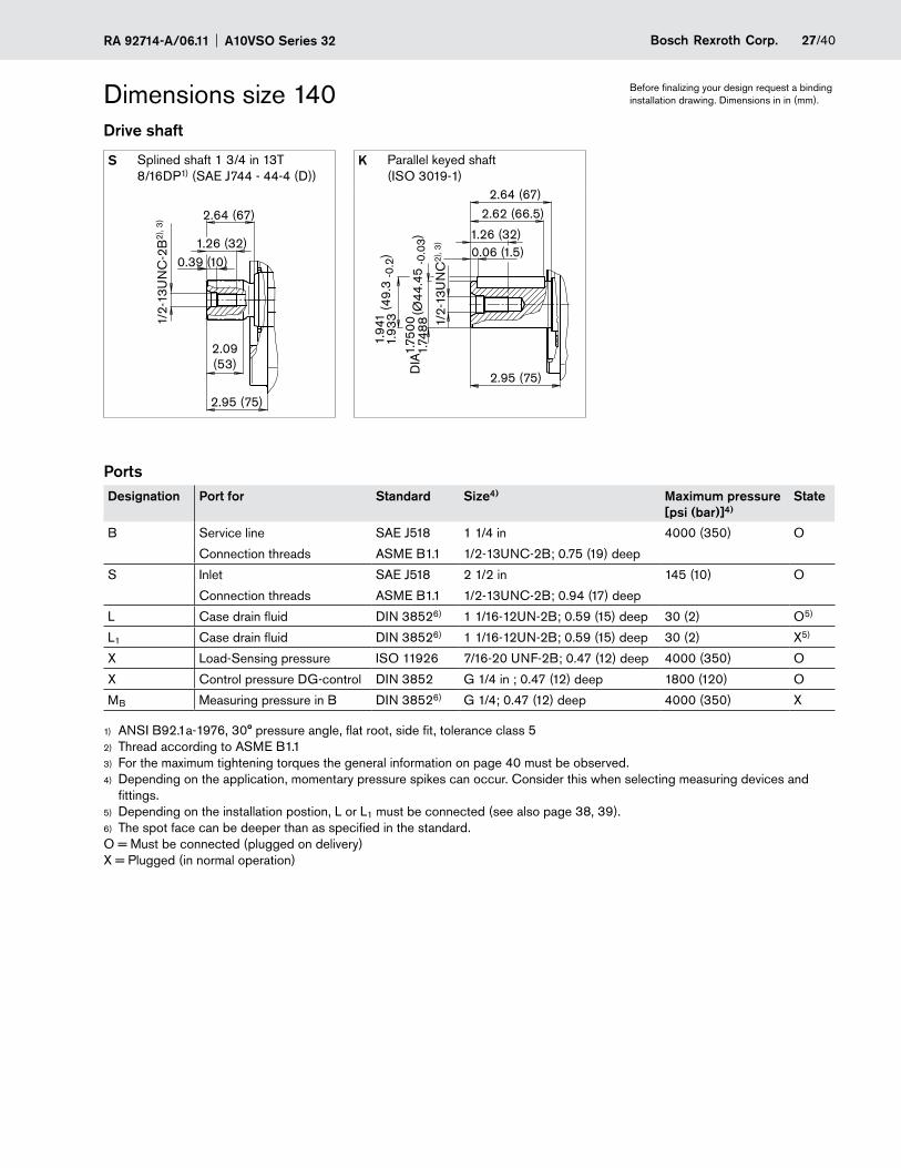
Before finalizing your design request a binding installation drawing. Dimensions in in (mm).Dimensions size 140
Drive shaft
S Splined shaft 1 3/4 in 13T 8/16DP1) (SAE J744 - 44-4 (D))
K Parallel keyed shaft (ISO 3019-1)
PortsDesignation Port for Standard Size4) Maximum pressure
[psi (bar)]4)State
B Service line SAE J518 1 1/4 in 4000 (350) O
Connection threads ASME B1.1 1/2-13UNC-2B; 0.75 (19) deep
S Inlet SAE J518 2 1/2 in 145 (10) O
Connection threads ASME B1.1 1/2-13UNC-2B; 0.94 (17) deep
L Case drain fluid DIN 38526) 1 1/16-12UN-2B; 0.59 (15) deep 30 (2) O5)
L1 Case drain fluid DIN 38526) 1 1/16-12UN-2B; 0.59 (15) deep 30 (2) X5)
X Load-Sensing pressure ISO 11926 7/16-20 UNF-2B; 0.47 (12) deep 4000 (350) O
X Control pressure DG-control DIN 3852 G 1/4 in ; 0.47 (12) deep 1800 (120) O
MB Measuring pressure in B DIN 38526) G 1/4; 0.47 (12) deep 4000 (350) X
ANSI B92.1a-1976, 30° pressure angle, flat root, side fit, tolerance class 51)
Thread according to ASME B1.12)
For the maximum tightening torques the general information on page 40 must be observed.3)
Depending on the application, momentary pressure spikes can occur. Consider this when selecting measuring devices and 4)
fittings.Depending on the installation postion, L or L5) 1 must be connected (see also page 38, 39).The spot face can be deeper than as specified in the standard.6)
O = Must be connected (plugged on delivery) X = Plugged (in normal operation)
2.95 (75)
1.26 (32)0.39 (10)
2.64 (67)
2.09(53)
1/2-
13U
NC
-2B
2), 3
)
(Ø44
.45
-0.0
3)1.
7488
DIA
1.75
00 1/2-
13U
NC
2), 3
)
(49.
3 -0
.2)
1.94
11.
933
2.95 (75)
0.06 (1.5)1.26 (32)
2.64 (67)
2.62 (66.5)
A10VSO Series 32 RA 92714-A/06.1128/40 Bosch Rexroth Corp.
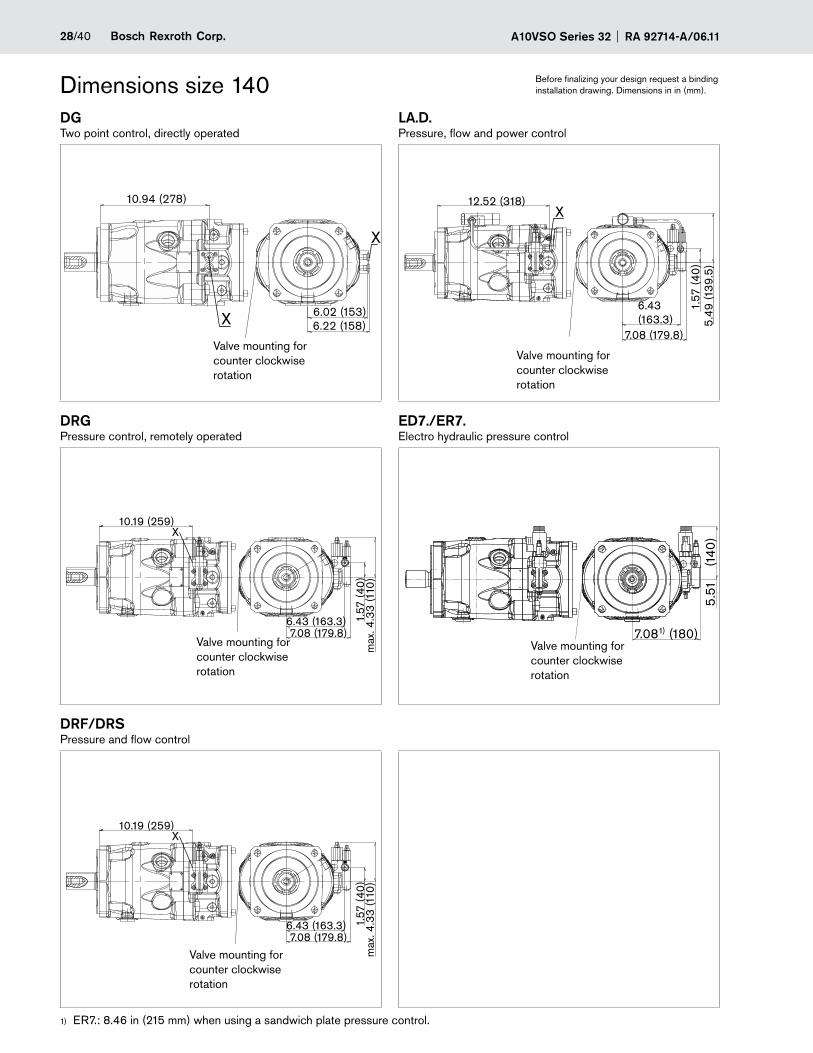
Before finalizing your design request a binding installation drawing. Dimensions in in (mm).Dimensions size 140
DGTwo point control, directly operated
LA.D.Pressure, flow and power control
DRGPressure control, remotely operated
ED7./ER7.Electro hydraulic pressure control
DRF/DRSPressure and flow control
ER7.: 8.46 in (215 mm) when using a sandwich plate pressure control.1)
6.02 (153)6.22 (158)
10.94 (278)
X
XX
10.19 (259)X
max
. 4.3
3 (1
10)
6.43 (163.3) 1.57
(40
)
7.08 (179.8)
X
10.19 (259)X
max
. 4.3
3 (1
10)
6.43 (163.3) 1.57
(40
)
7.08 (179.8)
X
1.57
(40
)
12.52 (318)
5.49
(139
.5)
6.43(163.3)
7.08 (179.8)
7.081) (180)
5.51
(1
40)
X
Valve mounting for counter clockwise rotation
Valve mounting for counter clockwise rotation
Valve mounting for counter clockwise rotation
Valve mounting for counter clockwise rotation
Valve mounting for counter clockwise rotation
29/40Bosch Rexroth Corp.RA 92714-A/06.11 A10VSO Series 32
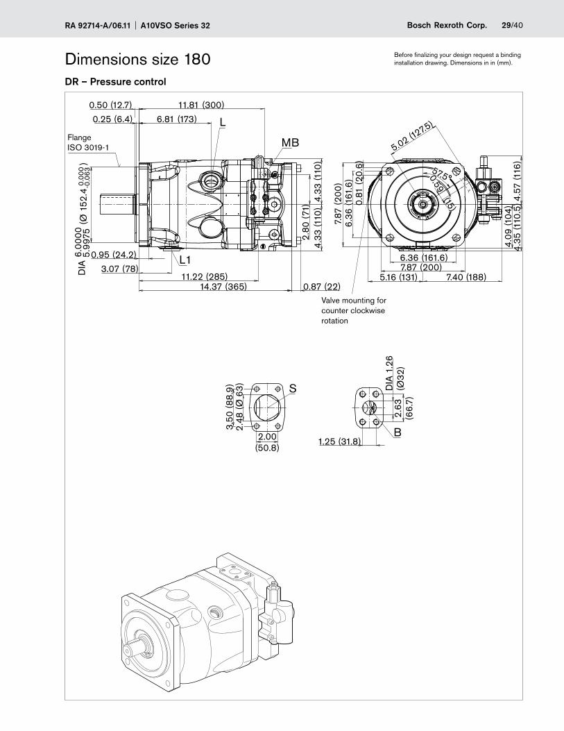
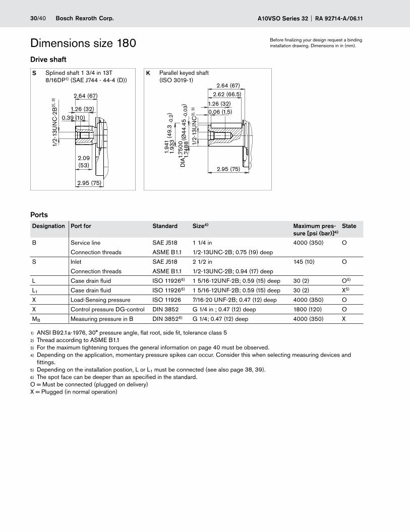
Before finalizing your design request a binding installation drawing. Dimensions in in (mm).Dimensions size 180
DR – Pressure control
4.57
(116
)
0.87 (22)
0.81
(20.
6)
7.87 (200)
(Ø 1
52.4
)
5.99
75D
IA6.
0000
0.00
0-0
.063
2.63
(66.
7)
DIA
1.2
6(Ø
32)
1.25 (31.8)
14.37 (365)
3.07 (78)11.22 (285)
0.95 (24.2)
0.25 (6.4)
0.50 (12.7)
6.81 (173)
11.81 (300)
2.48
(Ø 6
3)
4.33
(110
)4.
33 (1
10)
S
4.09
(104
)4.
35 (1
10.5
)
0.59 (15)
6.36
(161
.6)
6.36 (161.6)
MB
B
L
L1
2.80
(71)
7.87
(200
)
57.5°
7.40 (188)
5.02 (127.5)
3.50
(88.
9)
2.00(50.8)
5.16 (131)
Flange ISO 3019-1
Valve mounting for counter clockwise rotation
A10VSO Series 32 RA 92714-A/06.1130/40 Bosch Rexroth Corp.
Dimensions size 180Drive shaft
S Splined shaft 1 3/4 in 13T 8/16DP1) (SAE J744 - 44-4 (D))
K Parallel keyed shaft (ISO 3019-1)
PortsDesignation Port for Standard Size4) Maximum pres-
sure [psi (bar)]4)State
B Service line SAE J518 1 1/4 in 4000 (350) O
Connection threads ASME B1.1 1/2-13UNC-2B; 0.75 (19) deep
S Inlet SAE J518 2 1/2 in 145 (10) O
Connection threads ASME B1.1 1/2-13UNC-2B; 0.94 (17) deep
L Case drain fluid ISO 119266) 1 5/16-12UNF-2B; 0.59 (15) deep 30 (2) O5)
L1 Case drain fluid ISO 119266) 1 5/16-12UNF-2B; 0.59 (15) deep 30 (2) X5)
X Load-Sensing pressure ISO 11926 7/16-20 UNF-2B; 0.47 (12) deep 4000 (350) O
X Control pressure DG-control DIN 3852 G 1/4 in ; 0.47 (12) deep 1800 (120) O
MB Measuring pressure in B DIN 38526) G 1/4; 0.47 (12) deep 4000 (350) X
ANSI B92.1a-1976, 30° pressure angle, flat root, side fit, tolerance class 51)
Thread according to ASME B1.12)
For the maximum tightening torques the general information on page 40 must be observed.3)
Depending on the application, momentary pressure spikes can occur. Consider this when selecting measuring devices and 4)
fittings.Depending on the installation postion, L or L5) 1 must be connected (see also page 38, 39).The spot face can be deeper than as specified in the standard.6)
O = Must be connected (plugged on delivery) X = Plugged (in normal operation)
Before finalizing your design request a binding installation drawing. Dimensions in in (mm).
2.95 (75)
1.26 (32)0.39 (10)
2.64 (67)
2.09(53)
1/2-
13U
NC
-2B
2), 3
)
(Ø44
.45
-0.0
3)1.
7488
DIA
1.75
00 1/2-
13U
NC
2), 3
)
(49.
3 -0
.2)
1.94
11.
933
2.95 (75)
0.06 (1.5)1.26 (32)
2.64 (67)
2.62 (66.5)
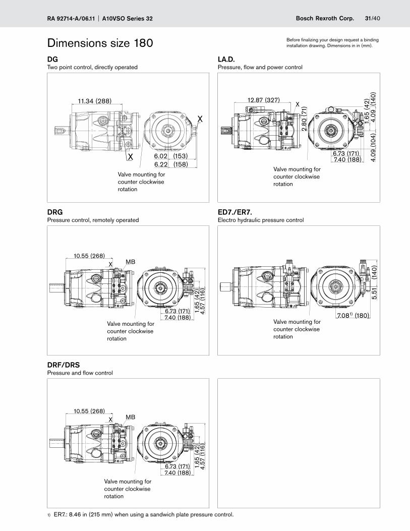
31/40Bosch Rexroth Corp.RA 92714-A/06.11 A10VSO Series 32
Dimensions size 180DGTwo point control, directly operated
LA.D.Pressure, flow and power control
DRGPressure control, remotely operated
ED7./ER7.Electro hydraulic pressure control
DRF/DRSPressure and flow control
ER7.: 8.46 in (215 mm) when using a sandwich plate pressure control.1)
Before finalizing your design request a binding installation drawing. Dimensions in in (mm).
4.57
(116
)
10.55 (268)MBX
6.73 (171) 1.65
(42)
7.40 (188)
4.57
(116
)
10.55 (268)MBX
6.73 (171) 1.65
(42)
7.40 (188)
6.02 (153)6.22 (158)
11.34 (288)
X
X
1.65
(42)
6.73 (171)
4.09
(14
0)
12.87 (327)
4.09
(104
)
X
2.80
(71)
7.40 (188)
5.51
(1
40)
X
7.081) (180)
Valve mounting for counter clockwise rotation
Valve mounting for counter clockwise rotation
Valve mounting for counter clockwise rotation
Valve mounting for counter clockwise rotation
Valve mounting for counter clockwise rotation
A10VSO Series 32 RA 92714-A/06.1132/40 Bosch Rexroth Corp.
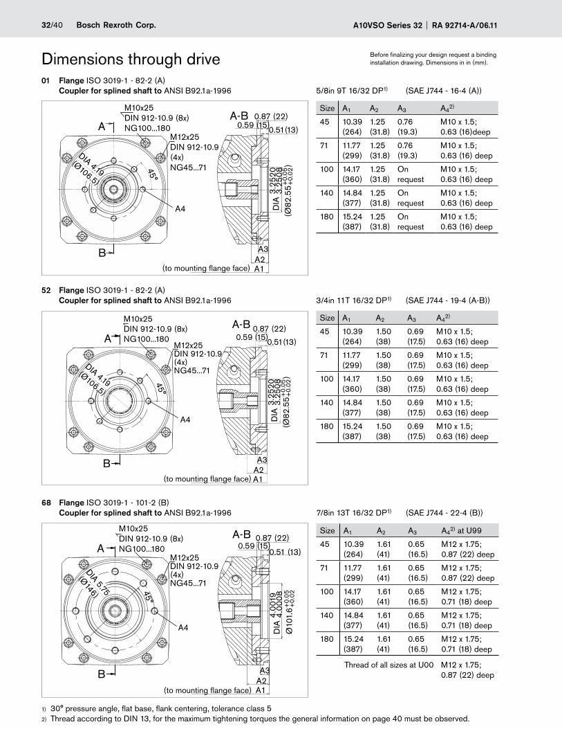
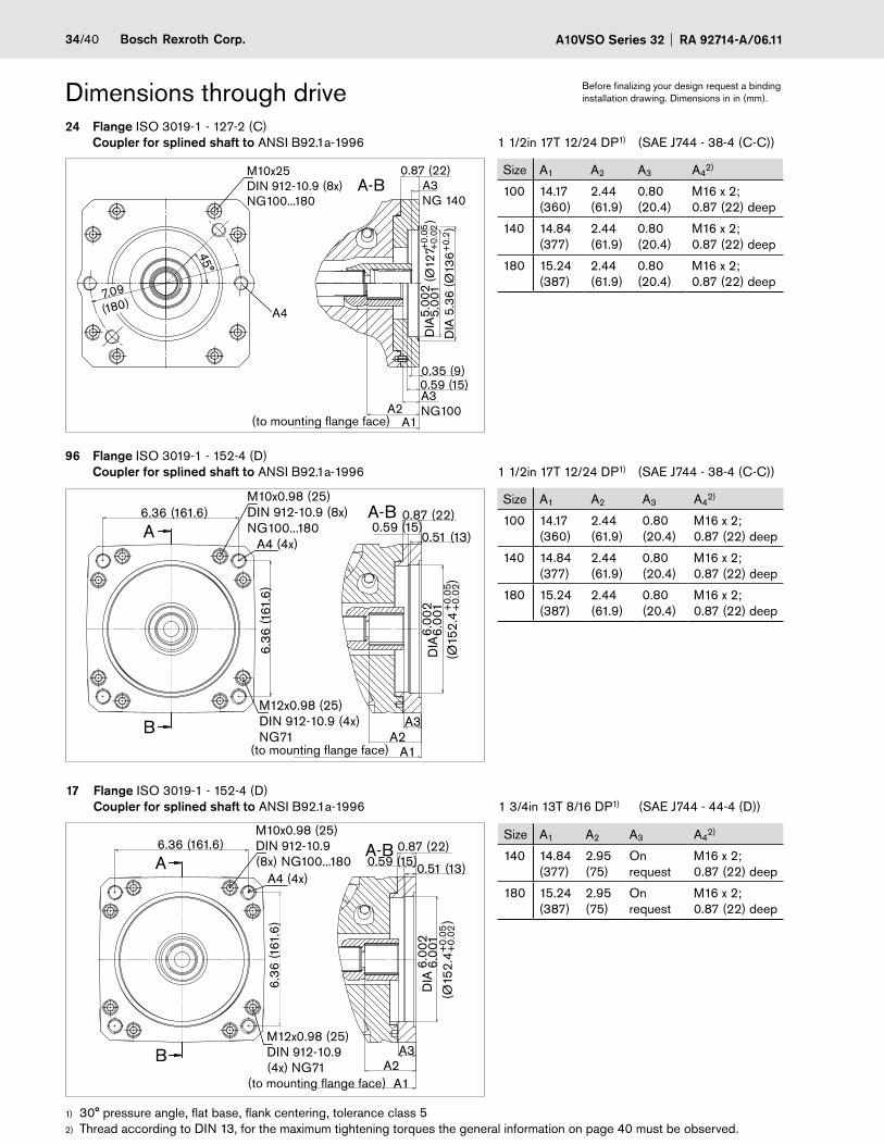
Before finalizing your design request a binding installation drawing. Dimensions in in (mm).Dimensions through drive
30° pressure angle, flat base, flank centering, tolerance class 51)
Thread according to DIN 13, 2) for the maximum tightening torques the general information on page 40 must be observed.
01 Flange ISO 3019-1 - 82-2 (A) Coupler for splined shaft to ANSI B92.1a-1996 5/8in 9T 16/32 DP1) (SAE J744 - 16-4 (A))
52 Flange ISO 3019-1 - 82-2 (A) Coupler for splined shaft to ANSI B92.1a-1996 3/4in 11T 16/32 DP1) (SAE J744 - 19-4 (A-B))
68 Flange ISO 3019-1 - 101-2 (B) Coupler for splined shaft to ANSI B92.1a-1996 7/8in 13T 16/32 DP1) (SAE J744 - 22-4 (B))
Size A1 A2 A3 A42)
45 10.39 (264)
1.25 (31.8)
0.76 (19.3)
M10 x 1.5; 0.63 (16)deep
71 11.77 (299)
1.25 (31.8)
0.76 (19.3)
M10 x 1.5; 0.63 (16) deep
100 14.17 (360)
1.25 (31.8)
On request
M10 x 1.5; 0.63 (16) deep
140 14.84 (377)
1.25 (31.8)
On request
M10 x 1.5; 0.63 (16) deep
180 15.24 (387)
1.25 (31.8)
On request
M10 x 1.5; 0.63 (16) deep
Size A1 A2 A3 A42)
45 10.39 (264)
1.50 (38)
0.69 (17.5)
M10 x 1.5; 0.63 (16) deep
71 11.77 (299)
1.50 (38)
0.69 (17.5)
M10 x 1.5; 0.63 (16) deep
100 14.17 (360)
1.50 (38)
0.69 (17.5)
M10 x 1.5; 0.63 (16) deep
140 14.84 (377)
1.50 (38)
0.69 (17.5)
M10 x 1.5; 0.63 (16) deep
180 15.24 (387)
1.50 (38)
0.69 (17.5)
M10 x 1.5; 0.63 (16) deep
Size A1 A2 A3 A42) at U99
45 10.39 (264)
1.61 (41)
0.65 (16.5)
M12 x 1.75; 0.87 (22) deep
71 11.77 (299)
1.61 (41)
0.65 (16.5)
M12 x 1.75; 0.87 (22) deep
100 14.17 (360)
1.61 (41)
0.65 (16.5)
M12 x 1.75; 0.71 (18) deep
140 14.84 (377)
1.61 (41)
0.65 (16.5)
M12 x 1.75; 0.71 (18) deep
180 15.24 (387)
1.61 (41)
0.65 (16.5)
M12 x 1.75; 0.71 (18) deep
Thread of all sizes at U00 M12 x 1.75; 0.87 (22) deepA3
A4
A2
0.59 (15)0.87 (22)
Ø10
1.6
DIA
4.00
194.
0008
+0.
05+
0.02
0.51 (13)
A-B
A1
A
B
45°
DIA 5.75
(Ø146)
M10x25DIN 912-10.9 (8x)NG100...180
M12x25 DIN 912-10.9(4x)NG45...71
A3A2
A-B
A1
A
B
45°
M10x25DIN 912-10.9 (8x)NG100...180
M12x25 DIN 912-10.9(4x)NG45...71
A4
0.87 (22)0.59 (15)0.51(13)
DIA 4.19(Ø106.5)
(Ø82
.55
)D
IA3.
2520
3.25
08+
0.05
+0.
02
A3
A4
A2
0.87 (22)0.59 (15)0.51(13)
DIA 4.19(Ø106.5)
(Ø82
.55
)D
IA3.
2520
3.25
08+
0.05
+0.
02
A-BM10x25DIN 912-10.9 (8x)NG100...180
A1
A
B
45°
M12x25 DIN 912-10.9(4x)NG45...71
(to mounting flange face)
(to mounting flange face)
(to mounting flange face)
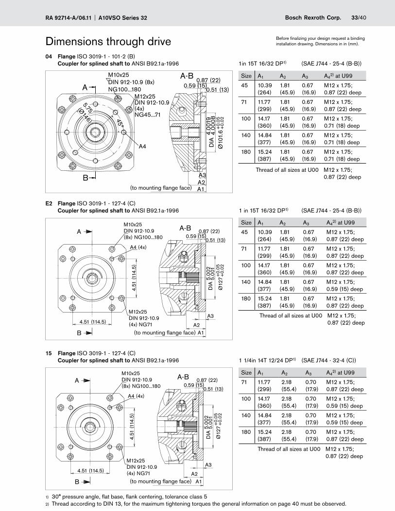
33/40Bosch Rexroth Corp.RA 92714-A/06.11 A10VSO Series 32
Before finalizing your design request a binding installation drawing. Dimensions in in (mm).
30° pressure angle, flat base, flank centering, tolerance class 51)
Thread according to DIN 13, 2) for the maximum tightening torques the general information on page 40 must be observed.
04 Flange ISO 3019-1 - 101-2 (B) Coupler for splined shaft to ANSI B92.1a-1996 1in 15T 16/32 DP1) (SAE J744 - 25-4 (B-B))
E2 Flange ISO 3019-1 - 127-4 (C) Coupler for splined shaft to ANSI B92.1a-1996 1 in 15T 16/32 DP1) (SAE J744 - 25-4 (B-B))
Size A1 A2 A3 A42) at U99
45 10.39 (264)
1.81 (45.9)
0.67 (16.9)
M12 x 1.75; 0.87 (22) deep
71 11.77 (299)
1.81 (45.9)
0.67 (16.9)
M12 x 1.75; 0.87 (22) deep
100 14.17 (360)
1.81 (45.9)
0.67 (16.9)
M12 x 1.75; 0.71 (18) deep
140 14.84 (377)
1.81 (45.9)
0.67 (16.9)
M12 x 1.75; 0.71 (18) deep
180 15.24 (387)
1.81 (45.9)
0.67 (16.9)
M12 x 1.75; 0.71 (18) deep
Size A1 A2 A3 A42) at U99
45 10.39 (264)
1.81 (45.9)
0.67 (16.9)
M12 x 1.75; 0.87 (22) deep
71 11.77 (299)
1.81 (45.9)
0.67 (16.9)
M12 x 1.75; 0.87 (22) deep
100 14.17 (360)
1.81 (45.9)
0.67 (16.9)
M12 x 1.75; 0.87 (22) deep
140 14.84 (377)
1.81 (45.9)
0.67 (16.9)
M12 x 1.75; 0.59 (15) deep
180 15.24 (387)
1.81 (45.9)
0.67 (16.9)
M12 x 1.75; 0.87 (22) deep
Dimensions through drive
15 Flange ISO 3019-1 - 127-4 (C) Coupler for splined shaft to ANSI B92.1a-1996 1 1/4in 14T 12/24 DP1) (SAE J744 - 32-4 (C))
Size A1 A2 A3 A42) at U99
71 11.77 (299)
2.18 (55.4)
0.70 (17.9)
M12 x 1.75; 0.87 (22) deep
100 14.17 (360)
2.18 (55.4)
0.70 (17.9)
M12 x 1.75; 0.59 (15) deep
140 14.84 (377)
2.18 (55.4)
0.70 (17.9)
M12 x 1.75; 0.59 (15) deep
180 15.24 (387)
2.18 (55.4)
0.70 (17.9)
M12 x 1.75; 0.87 (22) deep
Thread of all sizes at U00 M12 x 1.75; 0.87 (22) deep
Thread of all sizes at U00 M12 x 1.75; 0.87 (22) deep
Thread of all sizes at U00 M12 x 1.75; 0.87 (22) deep
A-B
A3
A4
A2
0.59 (15)0.87 (22)
Ø10
1.6
DIA
4.00
194.
0008
+0.
05+
0.02
A1
A
B
45°
0.51 (13)
5.75(Ø146)
M10x25DIN 912-10.9 (8x)NG100...180
M12x25 DIN 912-10.9(4x)NG45...71
4.51 (114.5)
4.51
(114
.5)
Ø12
7
DIA
5.00
25.
001
+0.
05+
0.02
A
B
A4 (4x)
M10x25DIN 912-10.9(8x) NG100...180
M12x25DIN 912-10.9(4x) NG71
A3
A2A1
0.51 (13)0.59 (15)
0.87 (22)A-B
4.51 (114.5)
4.51
(114
.5)
Ø12
7
DIA
5.00
25.
001
+0.
05+
0.02
A
B
A4 (4x)
M10x25DIN 912-10.9(8x) NG100...180
M12x25DIN 912-10.9(4x) NG71
A3
A2A1
0.51 (13)0.59 (15)
0.87 (22)A-B
(to mounting flange face)
(to mounting flange face)
(to mounting flange face)
A10VSO Series 32 RA 92714-A/06.1134/40 Bosch Rexroth Corp.
Before finalizing your design request a binding installation drawing. Dimensions in in (mm).Dimensions through drive
30° pressure angle, flat base, flank centering, tolerance class 51)
Thread according to DIN 13, 2) for the maximum tightening torques the general information on page 40 must be observed.
24 Flange ISO 3019-1 - 127-2 (C) Coupler for splined shaft to ANSI B92.1a-1996 1 1/2in 17T 12/24 DP1) (SAE J744 - 38-4 (C-C))
96 Flange ISO 3019-1 - 152-4 (D) Coupler for splined shaft to ANSI B92.1a-1996 1 1/2in 17T 12/24 DP1) (SAE J744 - 38-4 (C-C))
17 Flange ISO 3019-1 - 152-4 (D) Coupler for splined shaft to ANSI B92.1a-1996 1 3/4in 13T 8/16 DP1) (SAE J744 - 44-4 (D))
Size A1 A2 A3 A42)
100 14.17 (360)
2.44 (61.9)
0.80 (20.4)
M16 x 2; 0.87 (22) deep
140 14.84 (377)
2.44 (61.9)
0.80 (20.4)
M16 x 2; 0.87 (22) deep
180 15.24 (387)
2.44 (61.9)
0.80 (20.4)
M16 x 2; 0.87 (22) deep
Size A1 A2 A3 A42)
100 14.17 (360)
2.44 (61.9)
0.80 (20.4)
M16 x 2; 0.87 (22) deep
140 14.84 (377)
2.44 (61.9)
0.80 (20.4)
M16 x 2; 0.87 (22) deep
180 15.24 (387)
2.44 (61.9)
0.80 (20.4)
M16 x 2; 0.87 (22) deep
Size A1 A2 A3 A42)
140 14.84 (377)
2.95 (75)
On request
M16 x 2; 0.87 (22) deep
180 15.24 (387)
2.95 (75)
On request
M16 x 2; 0.87 (22) deep
A3A2
0.51 (13)0.59 (15)
0.87 (22)
6.36
(161
.6)
(Ø15
2.4
)D
IA6.
002
6.00
1 +0.
05+
0.02
6.36 (161.6)M10x0.98 (25)DIN 912-10.9 (8x)NG100...180
A4 (4x)
A1
A
B
A-B
M12x0.98 (25)DIN 912-10.9 (4x)NG71
(Ø12
7
)
DIA
5.00
25.
001
+0.
05+
0.02
DIA
5.3
6 (Ø
136
)
+0.
2
45°
7.09
(180)
0.59 (15)
0.87 (22)
0.35 (9)
A-B
A3NG100
A3NG 140
A4
A2A1
M10x25DIN 912-10.9 (8x)NG100...180
0.51 (13)
A3A2
0.59 (15)0.87 (22)
6.36
(161
.6)
(Ø15
2.4
)
DIA
6.00
26.
001
+0.
05+
0.02
6.36 (161.6)M10x0.98 (25)DIN 912-10.9(8x) NG100...180
A4 (4x)
A1
A
B
A-B
M12x0.98 (25)DIN 912-10.9(4x) NG71
(to mounting flange face)
(to mounting flange face)
(to mounting flange face)
35/40Bosch Rexroth Corp.RA 92714-A/06.11 A10VSO Series 32
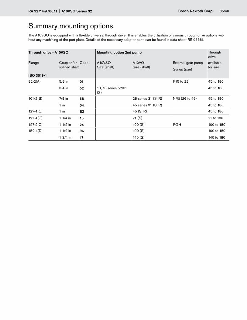
Summary mounting optionsThe A10VSO is equipped with a flexible universal through drive. This enables the utilization of various through drive options wit-hout any machining of the port plate. Details of the necessary adapter parts can be found in data sheet RE 95581.
Through drive - A10VSO Mounting option 2nd pump Through drive
Flange Coupler for splined shaft
Code A10VSO Size (shaft)
A10VO Size (shaft)
External gear pump
Series (size)
available for size
ISO 3019-1
82-2(A) 5/8 in
3/4 in
01
52 10, 18 series 52/31 (S)
F (5 to 22) 45 to 180
45 to 180
101-2(B) 7/8 in
1 in
68
04
28 series 31 (S, R)
45 series 31 (S, R)
N/G (26 to 49) 45 to 180
45 to 180
127-4(C) 1 in E2 45 (S, R) 45 to 180
127-4(C)
127-2(C)
1 1/4 in
1 1/2 in
15
24
71 (S)
100 (S) PGH
71 to 180
100 to 180
152-4(D) 1 1/2 in
1 3/4 in
96
17
100 (S)
140 (S)
100 to 180
140 to 180
A10VSO Series 32 RA 92714-A/06.1136/40 Bosch Rexroth Corp.
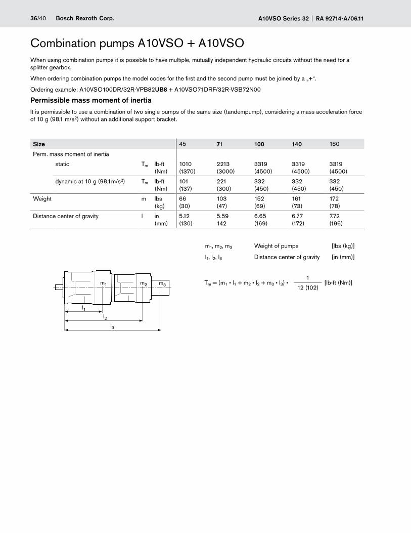
Combination pumps A10VSO + A10VSOWhen using combination pumps it is possible to have multiple, mutually independent hydraulic circuits without the need for a splitter gearbox.
When ordering combination pumps the model codes for the first and the second pump must be joined by a „+“.
Ordering example: A10VSO100DR/32R-VPB82UB8 + A10VSO71DRF/32R-VSB72N00
Permissible mass moment of inertiaIt is permissible to use a combination of two single pumps of the same size (tandempump), considering a mass acceleration force of 10 g (98,1 m/s2) without an additional support bracket.
Size 45 71 100 140 180
Perm. mass moment of inertia
static Tm lb-ft (Nm)
1010 (1370)
2213 (3000)
3319 (4500)
3319 (4500)
3319 (4500)
dynamic at 10 g (98,1m/s2) Tm lb-ft (Nm)
101 (137)
221 (300)
332 (450)
332 (450)
332 (450)
Weight m lbs (kg)
66 (30)
103 (47)
152 (69)
161 (73)
172 (78)
Distance center of gravity l in (mm)
5.12 (130)
5.59 142
6.65 (169)
6.77 (172)
7.72 (196)
m1, m2, m3 Weight of pumps [lbs (kg)]
l1, l2, l3 Distance center of gravity [in (mm)]
Tm = (m1 • l1 + m2 • l2 + m3 • l3) • 1
[lb-ft (Nm)]12 (102)
m1 m2 m3
l1l2
l3
37/40Bosch Rexroth Corp.RA 92714-A/06.11 A10VSO Series 32
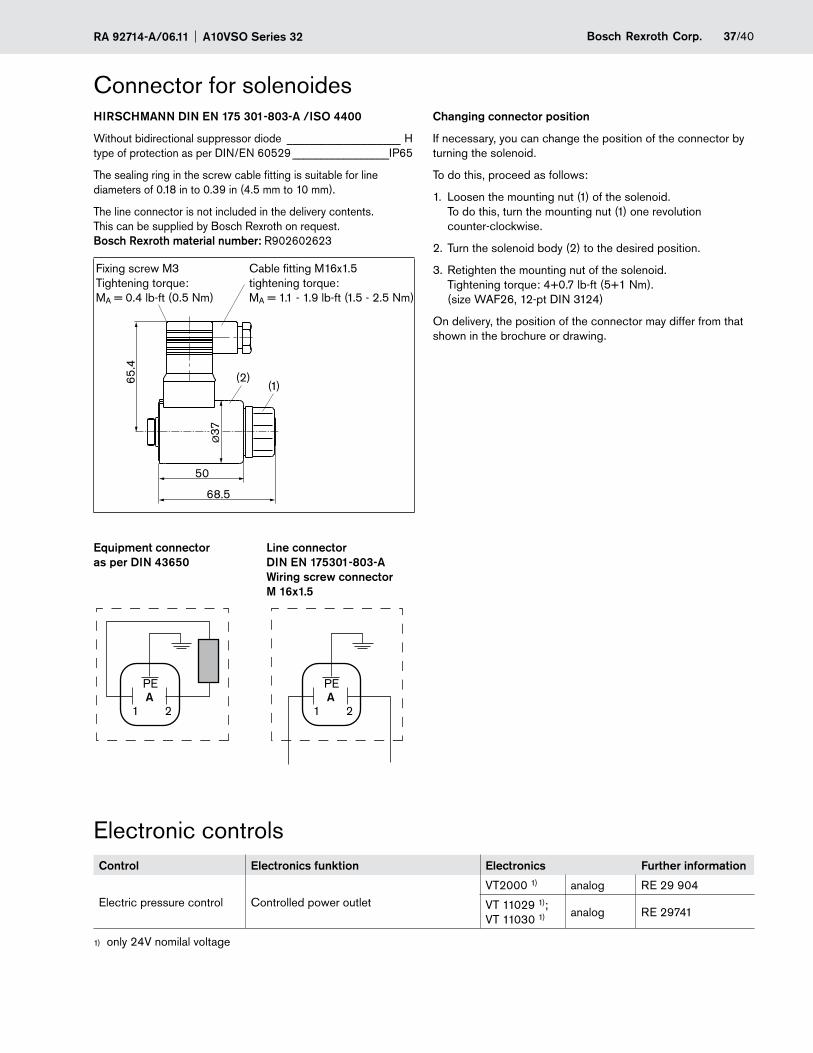
Connector for solenoidesHIRSCHMANN DIN EN 175 301-803-A /ISO 4400
Without bidirectional suppressor diode ____________________ H type of protection as per DIN/EN 60529 _________________IP65
The sealing ring in the screw cable fitting is suitable for line diameters of 0.18 in to 0.39 in (4.5 mm to 10 mm).
The line connector is not included in the delivery contents. This can be supplied by Bosch Rexroth on request. Bosch Rexroth material number: R902602623
50
Ø37
68.5
65.4
(2)(1)
Fixing screw M3 Tightening torque: MA = 0.4 lb-ft (0.5 Nm)
Cable fitting M16x1.5 tightening torque: MA = 1.1 - 1.9 lb-ft (1.5 - 2.5 Nm)
Equipment connector Line connector as per DIN 43650 DIN EN 175301-803-A Wiring screw connector M 16x1.5
Control Electronics funktion Electronics Further information
Electric pressure control Controlled power outletVT2000 1) analog RE 29 904
VT 11029 1); VT 11030 1) analog RE 29741
only 24V nomilal voltage1)
Electronic controls
Changing connector position
If necessary, you can change the position of the connector by turning the solenoid.
To do this, proceed as follows:
1. Loosen the mounting nut (1) of the solenoid. To do this, turn the mounting nut (1) one revolution counter-clockwise.
2. Turn the solenoid body (2) to the desired position.
3. Retighten the mounting nut of the solenoid. Tightening torque: 4+0.7 lb-ft (5+1 Nm). (size WAF26, 12-pt DIN 3124)
On delivery, the position of the connector may differ from that shown in the brochure or drawing.
1 2
PEA
1 2
PEA
A10VSO Series 32 RA 92714-A/06.1138/40 Bosch Rexroth Corp.
Installation notesGeneral
The axial piston unit must be filled with hydraulic fluid and air bled during commissioning and operation. This must also be observed following a longer standstill as the axial piston unit empty via the hydraulic lines.
Especially with the installation position "drive shaft upwards" or "drive shaft downward", attention must be paid to a comple-te filling and air bleeding since there is a risk, for example, of dry running.
The case drain fluid in the case interior must be directed to the reservoir via the highest case drain port (L1, L2, L3).
For combinations of multiple units, make sure that the respec-tive case pressure in each unit is not exceeded. In the event of pressure differences at the drain ports of the units, the shared drain line must be changed so that the minimum permissible case pressure of all connected units is not exceeded in any situation. If this is not possible, separate drain lines must be laid if necessary.
To achieve favorable noise values, decouple all connecting lines using elastic elements and avoid above-reservoir installa-tion.
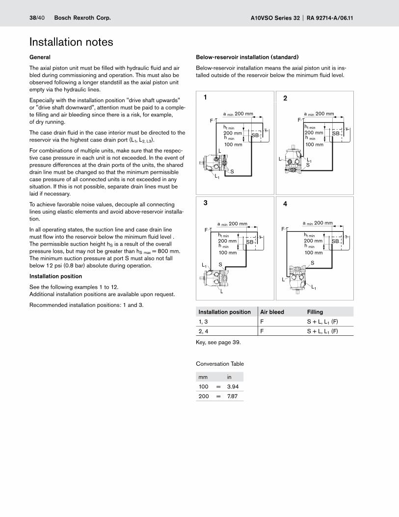
In all operating states, the suction line and case drain line must flow into the reservoir below the minimum fluid level . The permissible suction height hS is a result of the overall pressure loss, but may not be greater than hS max = 800 mm. The minimum suction pressure at port S must also not fall below 12 psi (0.8 bar) absolute during operation.
Installation position
See the following examples 1 to 12. Additional installation positions are available upon request.
Recommended installation positions: 1 and 3.
Below-reservoir installation (standard)
Below-reservoir installation means the axial piston unit is ins-talled outside of the reservoir below the minimum fluid level.
1 2
3 4
Installation position Air bleed Filling
1, 3 F S + L, L1 (F)
2, 4 F S + L, L1 (F)
Key, see page 39.
Conversation Table
mm in
100 = 3.94
200 = 7.87
L
L1S
ht min200 mm
ht min200 mmSB SB
a min 200 mm
a min 200 mm
a min 200 mm
a min 200 mm
F F
L
L1 S
ht min200 mm SB
F
L L1S
ht min200 mm SB
F
LL1
S
h min
100 mmh min
100 mm
h min
100 mmh min
100 mm
39/40Bosch Rexroth Corp.RA 92714-A/06.11 A10VSO Series 32
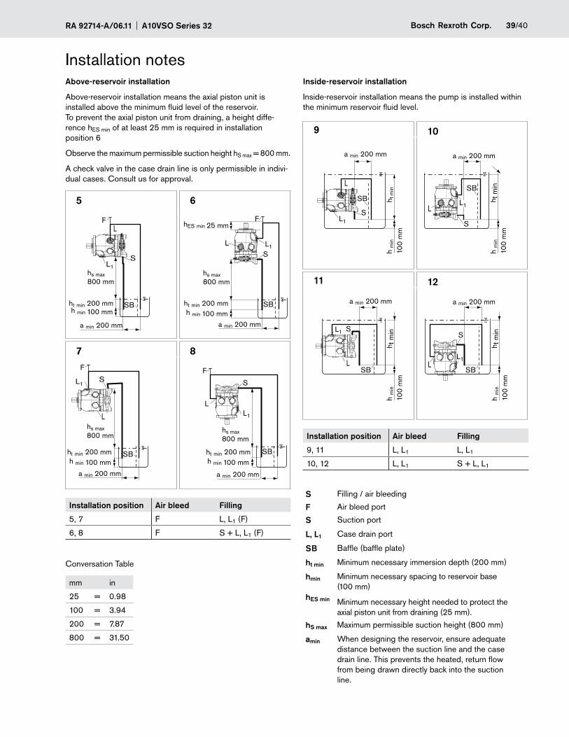
Installation notesInside-reservoir installation
Inside-reservoir installation means the pump is installed within the minimum reservoir fluid level.
9 10
11 12
Installation position Air bleed Filling
9, 11 L, L1 L, L1
10, 12 L, L1 S + L, L1
S Filling / air bleeding
F Air bleed port
S Suction port
L, L1 Case drain port
SB Baffle (baffle plate)
ht min Minimum necessary immersion depth (200 mm)
hmin
hES min
Minimum necessary spacing to reservoir base (100 mm)
Minimum necessary height needed to protect the axial piston unit from draining (25 mm).
hS max Maximum permissible suction height (800 mm)
amin When designing the reservoir, ensure adequate distance between the suction line and the case drain line. This prevents the heated, return flow from being drawn directly back into the suction line.
Above-reservoir installation
Above-reservoir installation means the axial piston unit is installed above the minimum fluid level of the reservoir. To prevent the axial piston unit from draining, a height diffe-rence hES min of at least 25 mm is required in installation position 6
Observe the maximum permissible suction height hS max = 800 mm.
A check valve in the case drain line is only permissible in indivi-dual cases. Consult us for approval.
5 6
7 8
Installation position Air bleed Filling
5, 7 F L, L1 (F)
6, 8 F S + L, L1 (F)
Conversation Table
mm in
25 = 0.98
100 = 3.94
200 = 7.87
800 = 31.50
L
L1S
F
hs max800 mm
ht min 200 mm
hs max800 mm
a min 200 mm
SB SB
S
a min 200 mm
a min 200 mm
a min 200 mm
F
L L1
L
L1S
F
hs max800 mm
hs max800 mm
SB SB
S
F
LL1
h min 100 mmht min 200 mmh min 100 mm
hES min 25 mm
ht min 200 mm ht min 200 mmh min 100 mm h min 100 mm
L
L1S
h t m
inh
min
100
mm
a min 200 mm
a min 200 mm
a min 200 mm
a min 200 mm
SB
L
L1 S
h t m
in
SB
LL1
S
h t m
inSB
LL1
S
h t m
in
SB
h m
in
100
mm
h m
in
100
mm
h m
in
100
mm
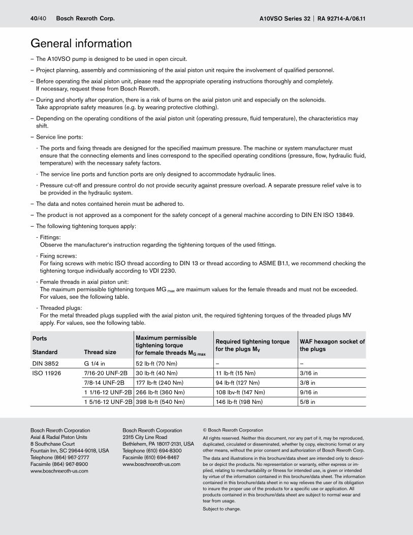
A10VSO Series 32 RA 92714-A/06.1140/40 Bosch Rexroth Corp.
© Bosch Rexroth Corporation
All rights reserved. Neither this document, nor any part of it, may be reproduced, duplicated, circulated or disseminated, whether by copy, electronic format or any other means, without the prior consent and authorization of Bosch Rexroth Corp.
The data and illustrations in this brochure/data sheet are intended only to descri-be or depict the products. No representation or warranty, either express or im-plied, relating to merchantability or fitness for intended use, is given or intended by virtue of the information contained in this brochure/data sheet. The information contained in this brochure/data sheet in no way relieves the user of its obligation to insure the proper use of the products for a specific use or application. All products contained in this brochure/data sheet are subject to normal wear and tear from usage.
Subject to change.
Bosch Rexroth CorporationAxial & Radial Piston Units8 Southchase CourtFountain Inn, SC 29644-9018, USATelephone (864) 967-2777Facsimile (864) 967-8900www.boschrexroth-us.com
Bosch Rexroth Corporation2315 City Line RoadBethlehem, PA 18017-2131, USATelephone (610) 694-8300Facsimile (610) 694-8467www.boschrexroth-us.com
General informationThe A10VSO pump is designed to be used in open circuit. –
Project planning, assembly and commissioning of the axial piston unit require the involvement of qualified personnel. –
Before operating the axial piston unit, please read the appropriate operating instructions thoroughly and completely. –If necessary, request these from Bosch Rexroth.
During and shortly after operation, there is a risk of burns on the axial piston unit and especially on the solenoids. –Take appropriate safety measures (e.g. by wearing protective clothing).
Depending on the operating conditions of the axial piston unit (operating pressure, fluid temperature), the characteristics may –shift.
Service line ports: –
The ports and fixing threads are designed for the specified maximum pressure. The machine or system manufacturer must -ensure that the connecting elements and lines correspond to the specified operating conditions (pressure, flow, hydraulic fluid, temperature) with the necessary safety factors.
The service line ports and function ports are only designed to accommodate hydraulic lines. -
Pressure cut-off and pressure control do not provide security against pressure overload. A separate pressure relief valve is to -be provided in the hydraulic system.
The data and notes contained herein must be adhered to. –
The product is not approved as a component for the safety concept of a general machine according to DIN EN ISO 13849. –
The following tightening torques apply: –
Fittings: -Observe the manufacturer‘s instruction regarding the tightening torques of the used fittings.
Fixing screws: -For fixing screws with metric ISO thread according to DIN 13 or thread according to ASME B1.1, we recommend checking the tightening torque individually according to VDI 2230.
Female threads in axial piston unit: -The maximum permissible tightening torques MG max are maximum values for the female threads and must not be exceeded. For values, see the following table.
Threaded plugs: -For the metal threaded plugs supplied with the axial piston unit, the required tightening torques of the threaded plugs MV apply. For values, see the following table.
Ports Maximum permissible tightening torque for female threads MG max
Required tightening torque for the plugs MV
WAF hexagon socket of the plugsStandard Thread size
DIN 3852 G 1/4 in 52 lb-ft (70 Nm) – –
ISO 11926 7/16-20 UNF-2B 30 lb-ft (40 Nm) 11 lb-ft (15 Nm) 3/16 in
7/8-14 UNF-2B 177 lb-ft (240 Nm) 94 lb-ft (127 Nm) 3/8 in
1 1/16-12 UNF-2B 266 lb-ft (360 Nm) 108 lbv-ft (147 Nm) 9/16 in
1 5/16-12 UNF-2B 398 lb-ft (540 Nm) 146 lb-ft (198 Nm) 5/8 in
Recommended