Aviation Safety Program
Atmospheric Environment Safety Technologies
(AEST) Project
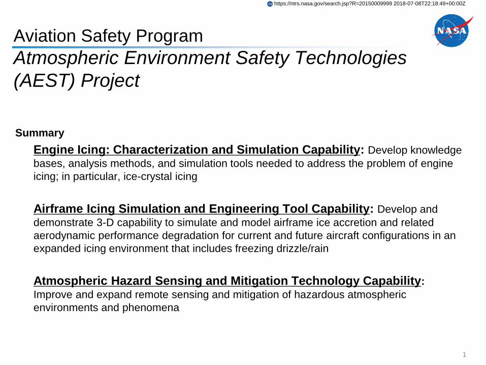
Summary
Engine Icing: Characterization and Simulation Capability: Develop knowledge
bases, analysis methods, and simulation tools needed to address the problem of engine
icing; in particular, ice-crystal icing
Airframe Icing Simulation and Engineering Tool Capability: Develop and
demonstrate 3-D capability to simulate and model airframe ice accretion and related
aerodynamic performance degradation for current and future aircraft configurations in an
expanded icing environment that includes freezing drizzle/rain
Atmospheric Hazard Sensing and Mitigation Technology Capability:
Improve and expand remote sensing and mitigation of hazardous atmospheric
environments and phenomena
1
https://ntrs.nasa.gov/search.jsp?R=20150009999 2018-07-08T22:18:49+00:00Z
National Aeronautics and Space Administration
www.nasa.gov
Aviation Safety ProgramAtmospheric Environment Safety Technologies (AEST) Project
Dr. Ron Colantonio
AEST Project Manager
2011 Annual Technical Meeting
May 10–12, 2011
St. Louis, MO
AEST Project Objective
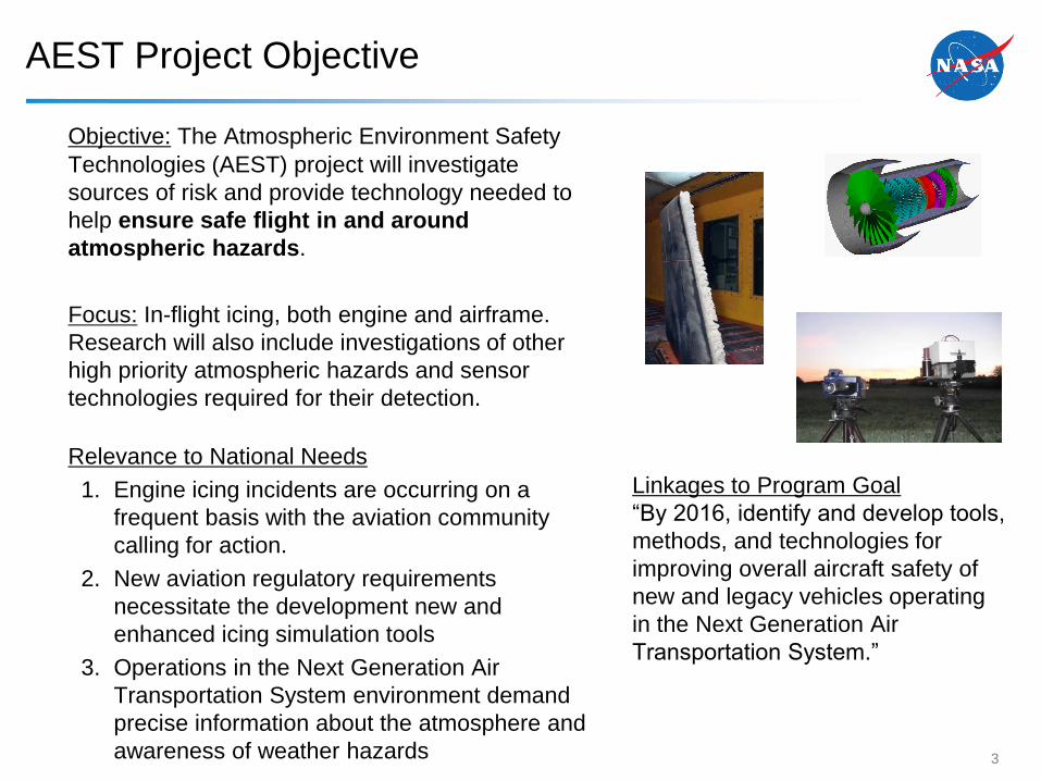
Objective: The Atmospheric Environment Safety
Technologies (AEST) project will investigate
sources of risk and provide technology needed to
help ensure safe flight in and around
atmospheric hazards.
Focus: In-flight icing, both engine and airframe.
Research will also include investigations of other
high priority atmospheric hazards and sensor
technologies required for their detection.
Relevance to National Needs
1. Engine icing incidents are occurring on a
frequent basis with the aviation community
calling for action.
2. New aviation regulatory requirements
necessitate the development new and
enhanced icing simulation tools
3. Operations in the Next Generation Air
Transportation System environment demand
precise information about the atmosphere and
awareness of weather hazards
Linkages to Program Goal
“By 2016, identify and develop tools,
methods, and technologies for
improving overall aircraft safety of
new and legacy vehicles operating
in the Next Generation Air
Transportation System.”
3
Summary of AEST Project Technical Challenges
Engine Icing: Characterization and Simulation Capability: Develop knowledge
bases, analysis methods, and simulation tools needed to address the problem of engine
icing; in particular, ice-crystal icing
Airframe Icing Simulation and Engineering Tool Capability: Develop and
demonstrate 3-D capability to simulate and model airframe ice accretion and related
aerodynamic performance degradation for current and future aircraft configurations in an
expanded icing environment that includes freezing drizzle/rain
Atmospheric Hazard Sensing and Mitigation Technology Capability:
Improve and expand remote sensing and mitigation of hazardous atmospheric
environments and phenomena
4
Technical Challenge (Engine Icing)
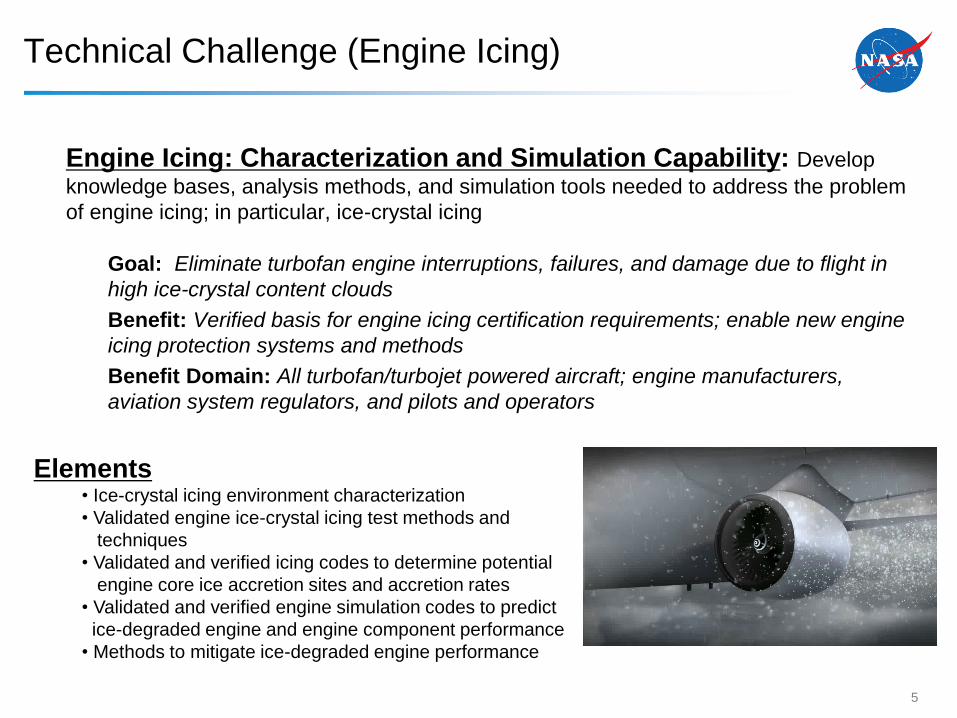
Engine Icing: Characterization and Simulation Capability: Develop
knowledge bases, analysis methods, and simulation tools needed to address the problem
of engine icing; in particular, ice-crystal icing
Goal: Eliminate turbofan engine interruptions, failures, and damage due to flight in
high ice-crystal content clouds
Benefit: Verified basis for engine icing certification requirements; enable new engine
icing protection systems and methods
Benefit Domain: All turbofan/turbojet powered aircraft; engine manufacturers,
aviation system regulators, and pilots and operators
5
Elements• Ice-crystal icing environment characterization
• Validated engine ice-crystal icing test methods and
techniques
• Validated and verified icing codes to determine potential
engine core ice accretion sites and accretion rates
• Validated and verified engine simulation codes to predict
ice-degraded engine and engine component performance
• Methods to mitigate ice-degraded engine performance
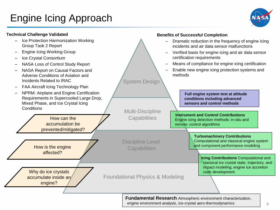
Technical Challenge Validated
– Ice Protection Harmonization Working
Group Task 2 Report
– Engine Icing Working Group
– Ice Crystal Consortium
– NASA Loss of Control Study Report
– NASA Report on Causal Factors and
Adverse Conditions of Aviation and
Incidents Related to IRAC
– FAA Aircraft Icing Technology Plan
– NPRM: Airplane and Engine Certification
Requirements in Supercooled Large Drop,
Mixed Phase, and Ice Crystal Icing
Conditions
Benefits of Successful Completion
– Dramatic reduction in the frequency of engine icing
incidents and air data sensor malfunctions
– Verified basis for engine icing and air data sensor
certification requirements
– Means of compliance for engine icing certification
– Enable new engine icing protection systems and
methods
Foundational Physics & Modeling
Discipline Level
Capabilities
Multi-Discipline
Capabilities
System Design
Icing Contributions Computational and
classical ice crystal state, trajectory, and
impact modeling; engine ice accretion
code development
Turbomachinery Contributions
Computational and classical engine system
and component performance modeling
Full engine system test at altitude
conditions including advanced
sensors and control methods
Instrument and Control Contributions
Engine icing detection methods: in-situ and
remote; control algorithms
How is the engine
affected?
How can the
accumulation be
prevented/mitigated?
Why do ice crystals
accumulate inside an
engine?
Fundamental Research Atmospheric environment characterization,
engine environment analysis, ice-crystal aero-thermodynamics
Engine Icing Approach
6
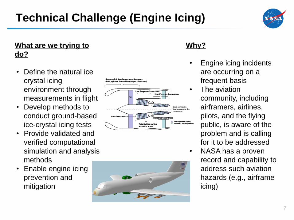
What are we trying to
do?
• Define the natural ice
crystal icing
environment through
measurements in flight
• Develop methods to
conduct ground-based
ice-crystal icing tests
• Provide validated and
verified computational
simulation and analysis
methods
• Enable engine icing
prevention and
mitigation
Why?
• Engine icing incidents
are occurring on a
frequent basis
• The aviation
community, including
airframers, airlines,
pilots, and the flying
public, is aware of the
problem and is calling
for it to be addressed
• NASA has a proven
record and capability to
address such aviation
hazards (e.g., airframe
icing)
Fan
Low Pressure Compressor
High Pressure Compressor
Intercompressor Bleed
Supercooled liquid water accretion areas
(inlet, spinner, fan and first stages of the core)
Potential ice particle
accretion areas
Core inlet stator
Core air travels
downstream to the
combustor
rotating blades (rotors)
stationary blades (stators)
Technical Challenge (Engine Icing)
7
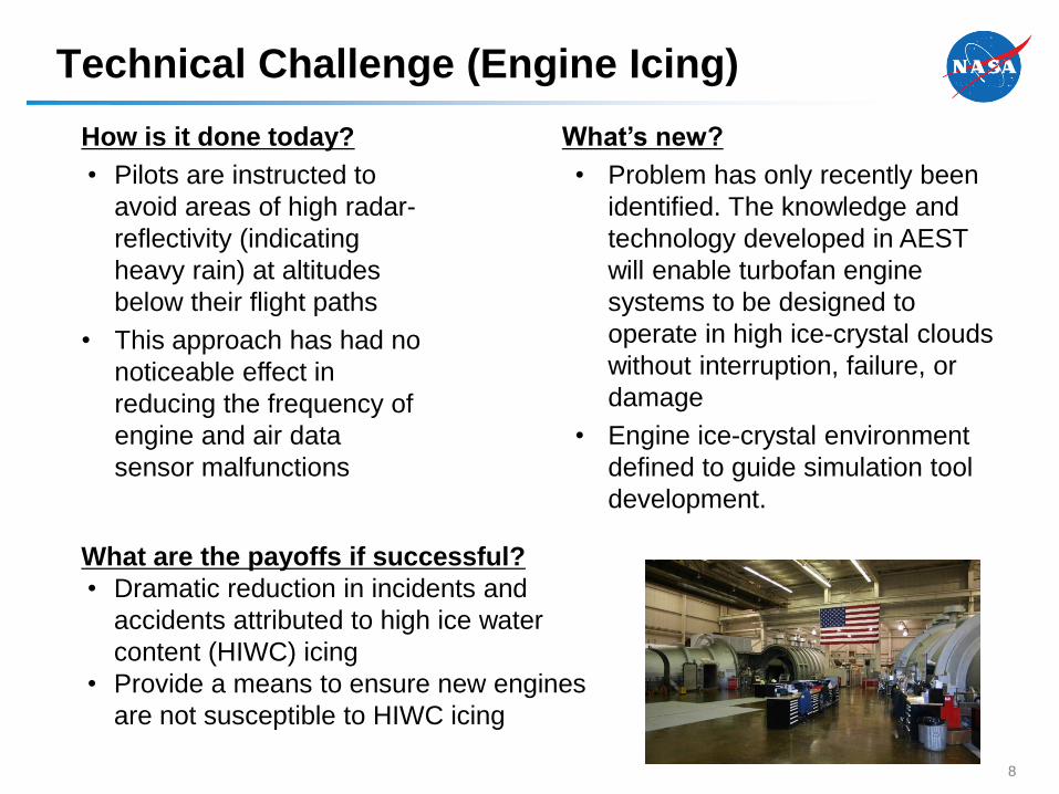
How is it done today?
• Pilots are instructed to
avoid areas of high radar-
reflectivity (indicating
heavy rain) at altitudes
below their flight paths
• This approach has had no
noticeable effect in
reducing the frequency of
engine and air data
sensor malfunctions
What’s new?
• Problem has only recently been
identified. The knowledge and
technology developed in AEST
will enable turbofan engine
systems to be designed to
operate in high ice-crystal clouds
without interruption, failure, or
damage
• Engine ice-crystal environment
defined to guide simulation tool
development.
What are the payoffs if successful?
• Dramatic reduction in incidents and
accidents attributed to high ice water
content (HIWC) icing
• Provide a means to ensure new engines
are not susceptible to HIWC icing
Technical Challenge (Engine Icing)
8
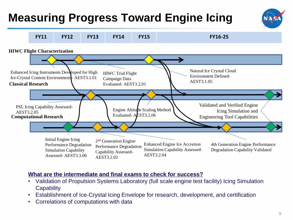
FY11 FY12 FY13 FY14 FY15 FY16-25
PSL Icing Capability Assessed-
AEST3.2.05
HIWC Trial Flight
Campaign Data
Evaluated- AEST3.2.01
Validated and Verified Engine
Icing Simulation and
Engineering Tool Capabilities
Initial Engine Icing
Performance Degradation
Simulation Capability
Assessed- AEST3.3.06
Enhanced Icing Instruments Developed for High
Ice-Crystal Content Environments- AEST3.1.01
Natural Ice Crystal Cloud
Environment Defined-
AEST3.1.05
HIWC Flight Characterization
Classical Research
Computational Research
Engine Altitude Scaling Method
Evaluated- AEST3.2.06
2nd Generation Engine
Performance Degradation
Capability Assessed-
AEST3.2.02
Enhanced Engine Ice Accretion
Simulation Capability Assessed-
AEST3.2.04
4th Generation Engine Performance
Degradation Capability Validated
What are the intermediate and final exams to check for success?
• Validation of Propulsion Systems Laboratory (full scale engine test facility) Icing Simulation
Capability
• Establishment of Ice-Crystal Icing Envelope for research, development, and certification
• Correlations of computations with data
Measuring Progress Toward Engine Icing
9
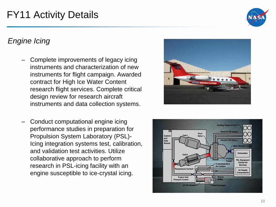
FY11 Activity Details
Engine Icing
– Complete improvements of legacy icing
instruments and characterization of new
instruments for flight campaign. Awarded
contract for High Ice Water Content
research flight services. Complete critical
design review for research aircraft
instruments and data collection systems.
– Conduct computational engine icing
performance studies in preparation for
Propulsion System Laboratory (PSL)-
Icing integration systems test, calibration,
and validation test activities. Utilize
collaborative approach to perform
research in PSL-icing facility with an
engine susceptible to ice-crystal icing.
10
Airframe Icing Simulation and Engineering Tool Capability:
Develop and demonstrate capability to simulate and model airframe ice accretion and
related aerodynamic performance degradation for current and future aircraft configurations
in an expanded icing environment that includes freezing drizzle/rain
Goal: Achieve acceptance of simulation tools for design and certification of swept wing configurations
over an expanded range of icing conditions
Benefit: Enable aircraft manufacturers to perform reliable icing assessments and build in effective icing
mitigation approaches for current and future aircraft; development of technology that enables safe flight
operations in an super-cooled large droplet environment
Benefit Domain: Aircraft and aircraft sub-system manufacturers and aviation system regulators
Elements:
• Computational Ice Accretion Simulation for Swept Wings
• Experimental Ice Accretion Simulation for Swept Wings
• Experimental Aerodynamic Simulation for Swept Wings
• Computational Aerodynamic Simulation for Swept Wings
• Computational Ice Accretion Simulation for Super-cooled Large Droplet (SLD) Icing
Conditions
• Experimental Ice Accretion Simulation for SLD Icing Conditions
• Ice Protection System Modeling
Technical Challenge (Airframe Icing)
11
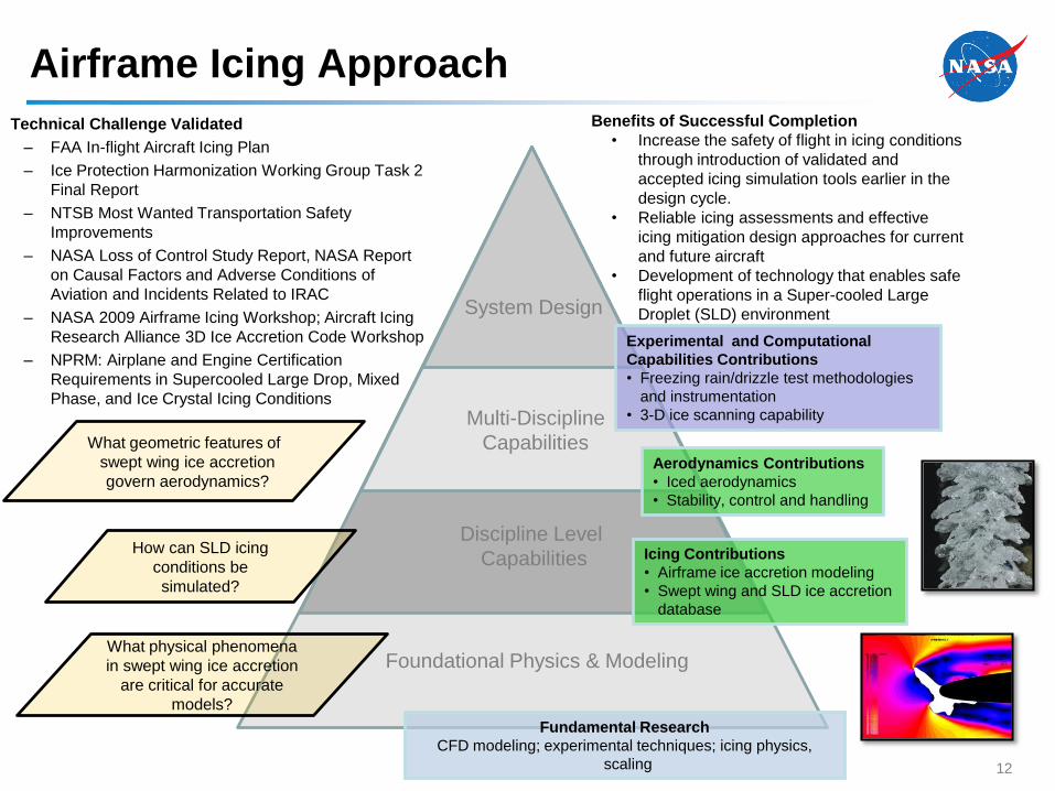
Benefits of Successful Completion
• Increase the safety of flight in icing conditions
through introduction of validated and
accepted icing simulation tools earlier in the
design cycle.
• Reliable icing assessments and effective
icing mitigation design approaches for current
and future aircraft
• Development of technology that enables safe
flight operations in a Super-cooled Large
Droplet (SLD) environment
Technical Challenge Validated
– FAA In-flight Aircraft Icing Plan
– Ice Protection Harmonization Working Group Task 2
Final Report
– NTSB Most Wanted Transportation Safety
Improvements
– NASA Loss of Control Study Report, NASA Report
on Causal Factors and Adverse Conditions of
Aviation and Incidents Related to IRAC
– NASA 2009 Airframe Icing Workshop; Aircraft Icing
Research Alliance 3D Ice Accretion Code Workshop
– NPRM: Airplane and Engine Certification
Requirements in Supercooled Large Drop, Mixed
Phase, and Ice Crystal Icing Conditions
Foundational Physics & Modeling
Discipline Level
Capabilities
Multi-Discipline
Capabilities
System Design
What physical phenomena
in swept wing ice accretion
are critical for accurate
models?
How can SLD icing
conditions be
simulated?
What geometric features of
swept wing ice accretion
govern aerodynamics?
Experimental and Computational
Capabilities Contributions
• Freezing rain/drizzle test methodologies
and instrumentation
• 3-D ice scanning capability
Aerodynamics Contributions
• Iced aerodynamics
• Stability, control and handling
Icing Contributions
• Airframe ice accretion modeling
• Swept wing and SLD ice accretion
database
Fundamental Research
CFD modeling; experimental techniques; icing physics,
scaling
Airframe Icing Approach
12
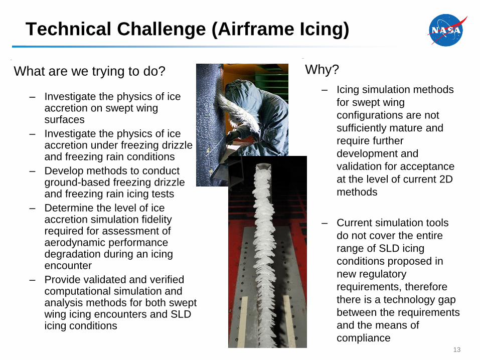
– Investigate the physics of ice accretion on swept wing surfaces
– Investigate the physics of ice accretion under freezing drizzle and freezing rain conditions
– Develop methods to conduct ground-based freezing drizzle and freezing rain icing tests
– Determine the level of ice accretion simulation fidelity required for assessment of aerodynamic performance degradation during an icing encounter
– Provide validated and verified computational simulation and analysis methods for both swept wing icing encounters and SLD icing conditions
Why?
– Icing simulation methods
for swept wing
configurations are not
sufficiently mature and
require further
development and
validation for acceptance
at the level of current 2D
methods
– Current simulation tools
do not cover the entire
range of SLD icing
conditions proposed in
new regulatory
requirements, therefore
there is a technology gap
between the requirements
and the means of
compliance
What are we trying to do?
Technical Challenge (Airframe Icing)
13
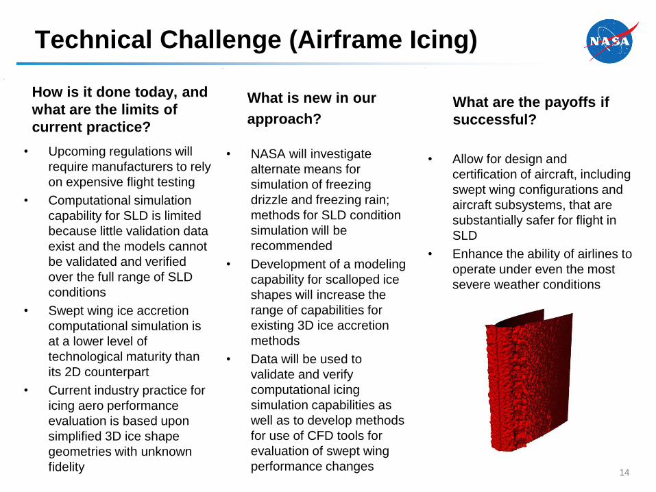
• NASA will investigate
alternate means for
simulation of freezing
drizzle and freezing rain;
methods for SLD condition
simulation will be
recommended
• Development of a modeling
capability for scalloped ice
shapes will increase the
range of capabilities for
existing 3D ice accretion
methods
• Data will be used to
validate and verify
computational icing
simulation capabilities as
well as to develop methods
for use of CFD tools for
evaluation of swept wing
performance changes
• Allow for design and
certification of aircraft, including
swept wing configurations and
aircraft subsystems, that are
substantially safer for flight in
SLD
• Enhance the ability of airlines to
operate under even the most
severe weather conditions
How is it done today, and
what are the limits of
current practice?
What is new in our
approach?What are the payoffs if
successful?
• Upcoming regulations will
require manufacturers to rely
on expensive flight testing
• Computational simulation
capability for SLD is limited
because little validation data
exist and the models cannot
be validated and verified
over the full range of SLD
conditions
• Swept wing ice accretion
computational simulation is
at a lower level of
technological maturity than
its 2D counterpart
• Current industry practice for
icing aero performance
evaluation is based upon
simplified 3D ice shape
geometries with unknown
fidelity
Technical Challenge (Airframe Icing)
14
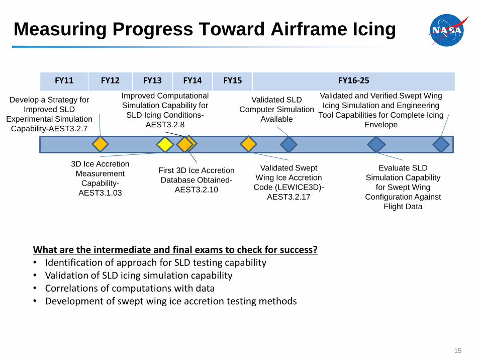
FY11 FY12 FY13 FY14 FY15 FY16-25
Develop a Strategy for
Improved SLD
Experimental Simulation
Capability-AEST3.2.7
First 3D Ice Accretion
Database Obtained-
AEST3.2.10
Validated and Verified Swept Wing
Icing Simulation and Engineering
Tool Capabilities for Complete Icing
Envelope
Validated Swept
Wing Ice Accretion
Code (LEWICE3D)-
AEST3.2.17
What are the intermediate and final exams to check for success?• Identification of approach for SLD testing capability• Validation of SLD icing simulation capability• Correlations of computations with data• Development of swept wing ice accretion testing methods
Validated SLD
Computer Simulation
Available
3D Ice Accretion
Measurement
Capability-
AEST3.1.03
Evaluate SLD
Simulation Capability
for Swept Wing
Configuration Against
Flight Data
Improved Computational
Simulation Capability for
SLD Icing Conditions-
AEST3.2.8
Measuring Progress Toward Airframe Icing
15
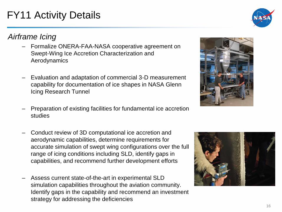
FY11 Activity Details
Airframe Icing– Formalize ONERA-FAA-NASA cooperative agreement on
Swept-Wing Ice Accretion Characterization and
Aerodynamics
– Evaluation and adaptation of commercial 3-D measurement
capability for documentation of ice shapes in NASA Glenn
Icing Research Tunnel
– Preparation of existing facilities for fundamental ice accretion
studies
– Conduct review of 3D computational ice accretion and
aerodynamic capabilities, determine requirements for
accurate simulation of swept wing configurations over the full
range of icing conditions including SLD, identify gaps in
capabilities, and recommend further development efforts
– Assess current state-of-the-art in experimental SLD
simulation capabilities throughout the aviation community.
Identify gaps in the capability and recommend an investment
strategy for addressing the deficiencies16
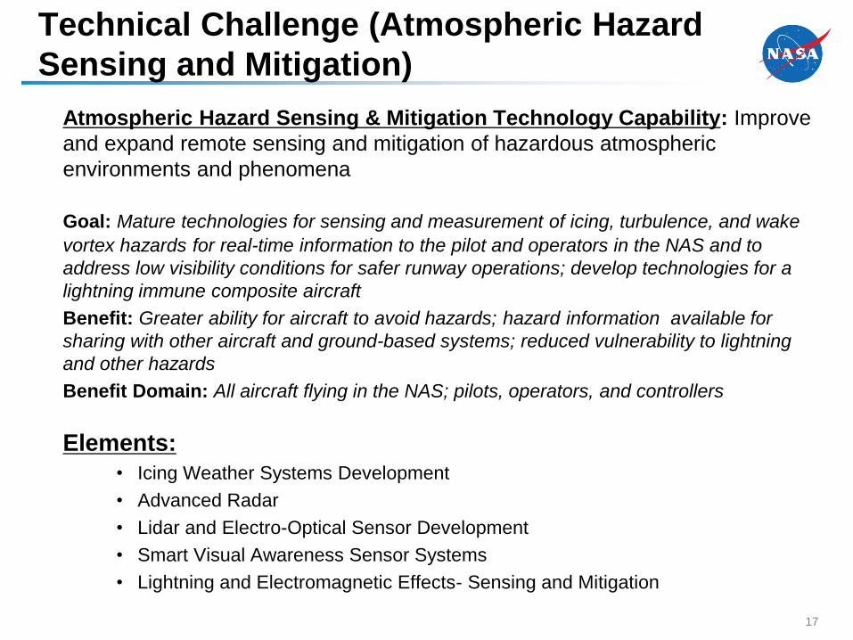
Atmospheric Hazard Sensing & Mitigation Technology Capability: Improve
and expand remote sensing and mitigation of hazardous atmospheric
environments and phenomena
Goal: Mature technologies for sensing and measurement of icing, turbulence, and wake
vortex hazards for real-time information to the pilot and operators in the NAS and to
address low visibility conditions for safer runway operations; develop technologies for a
lightning immune composite aircraft
Benefit: Greater ability for aircraft to avoid hazards; hazard information available for
sharing with other aircraft and ground-based systems; reduced vulnerability to lightning
and other hazards
Benefit Domain: All aircraft flying in the NAS; pilots, operators, and controllers
Elements:
• Icing Weather Systems Development
• Advanced Radar
• Lidar and Electro-Optical Sensor Development
• Smart Visual Awareness Sensor Systems
• Lightning and Electromagnetic Effects- Sensing and Mitigation
Technical Challenge (Atmospheric Hazard
Sensing and Mitigation)
17
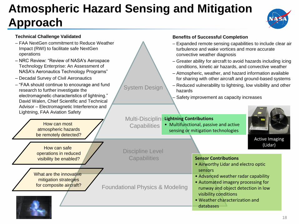
Benefits of Successful Completion
– Expanded remote sensing capabilities to include clear air
turbulence and wake vortices and more accurate
convective weather diagnosis
– Greater ability for aircraft to avoid hazards including icing
conditions, kinetic air hazards, and convective weather
– Atmospheric, weather, and hazard information available
for sharing with other aircraft and ground-based systems
– Reduced vulnerability to lightning, low visibility and other
hazards
– Safety improvement as capacity increases
Technical Challenge Validated
– FAA NextGen commitment to Reduce Weather
Impact (RWI) to facilitate safe NextGen
operations
– NRC Review: “Review of NASA's Aerospace
Technology Enterprise: An Assessment of
NASA's Aeronautics Technology Programs”
– Decadal Survey of Civil Aeronautics
– “FAA should continue to encourage and fund
research to further investigate the
electromagnetic characteristics of lightning.”
David Walen, Chief Scientific and Technical
Advisor – Electromagnetic Interference and
Lightning, FAA Aviation Safety
Active Imaging (Lidar)
Foundational Physics & Modeling
Discipline Level
Capabilities
Multi-Discipline
Capabilities
System Design
Sensor Contributions • Airworthy Lidar and electro optic
sensors• Advanced weather radar capability• Automated imagery processing for
runway and object detection in low visibility conditions
• Weather characterization and databases
Lightning Contributions • Multifunctional, passive and active
sensing or mitigation technologies
Atmospheric Hazard Sensing and Mitigation
Approach
18
How can most
atmospheric hazards
be remotely detected?
How can safe
operations in reduced
visibility be enabled?
What are the innovative
mitigation strategies
for composite aircraft?
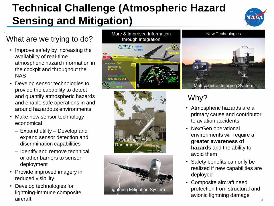
What are we trying to do?
• Improve safety by increasing the
availability of real-time
atmospheric hazard information in
the cockpit and throughout the
NAS
• Develop sensor technologies to
provide the capability to detect
and quantify atmospheric hazards
and enable safe operations in and
around hazardous environments
• Make new sensor technology
economical
– Expand utility – Develop and
expand sensor detection and
discrimination capabilities
– Identify and remove technical
or other barriers to sensor
deployment
• Provide improved imagery in
reduced visibility
• Develop technologies for
lightning-immune composite
aircraft
Why?
• Atmospheric hazards are a
primary cause and contributor
to aviation accidents
• NextGen operational
environments will require a
greater awareness of
hazards and the ability to
avoid them
• Safety benefits can only be
realized if new capabilities are
deployed
• Composite aircraft need
protection from structural and
avionic lightning damage
On
Board
Ground
Integrated WX
• Nowcast & Forecast
• On Board
• Ground-Based
• Satellite-Based
• Other Aircraft
Other
AircraftSatellite
New TechnologiesMore & Improved Information
through Integration
Multispectral Imaging System
Scanning
Radiometer
Technical Challenge (Atmospheric Hazard
Sensing and Mitigation)
Lightning Mitigation System
19
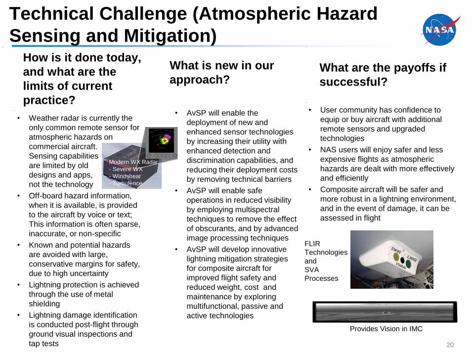
How is it done today,
and what are the
limits of current
practice?
• Weather radar is currently the
only common remote sensor for
atmospheric hazards on
commercial aircraft.
Sensing capabilities
are limited by old
designs and apps,
not the technology
• Off-board hazard information,
when it is available, is provided
to the aircraft by voice or text;
This information is often sparse,
inaccurate, or non-specific
• Known and potential hazards
are avoided with large,
conservative margins for safety,
due to high uncertainty
• Lightning protection is achieved
through the use of metal
shielding
• Lightning damage identification
is conducted post-flight through
ground visual inspections and
tap tests
• AvSP will enable the
deployment of new and
enhanced sensor technologies
by increasing their utility with
enhanced detection and
discrimination capabilities, and
reducing their deployment costs
by removing technical barriers
• AvSP will enable safe
operations in reduced visibility
by employing multispectral
techniques to remove the effect
of obscurants, and by advanced
image processing techniques
• AvSP will develop innovative
lightning mitigation strategies
for composite aircraft for
improved flight safety and
reduced weight, cost and
maintenance by exploring
multifunctional, passive and
active technologies
What are the payoffs if
successful?
• User community has confidence to
equip or buy aircraft with additional
remote sensors and upgraded
technologies
• NAS users will enjoy safer and less
expensive flights as atmospheric
hazards are dealt with more effectively
and efficiently
• Composite aircraft will be safer and
more robust in a lightning environment,
and in the event of damage, it can be
assessed in flight
Modern WX Radar
- Severe WX
- Windshear
- Turbulence
FLIR
Technologies
and
SVA
Processes
Provides Vision in IMC
What is new in our
approach?
Technical Challenge (Atmospheric Hazard
Sensing and Mitigation)
20
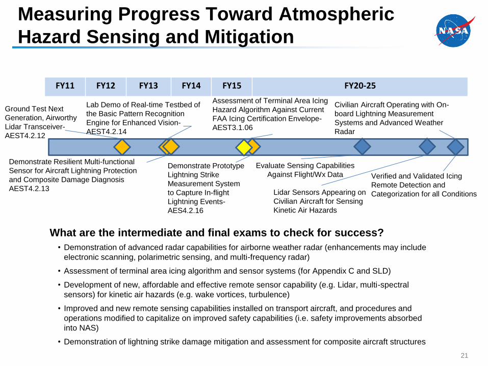
FY11 FY12 FY13 FY14 FY15 FY20-25
Ground Test Next
Generation, Airworthy
Lidar Transceiver-
AEST4.2.12
Civilian Aircraft Operating with On-
board Lightning Measurement
Systems and Advanced Weather
Radar
Demonstrate Resilient Multi-functional
Sensor for Aircraft Lightning Protection
and Composite Damage Diagnosis
AEST4.2.13
Assessment of Terminal Area Icing
Hazard Algorithm Against Current
FAA Icing Certification Envelope-
AEST3.1.06
Demonstrate Prototype
Lightning Strike
Measurement System
to Capture In-flight
Lightning Events-
AES4.2.16
• Demonstration of advanced radar capabilities for airborne weather radar (enhancements may include
electronic scanning, polarimetric sensing, and multi-frequency radar)
• Assessment of terminal area icing algorithm and sensor systems (for Appendix C and SLD)
• Development of new, affordable and effective remote sensor capability (e.g. Lidar, multi-spectral
sensors) for kinetic air hazards (e.g. wake vortices, turbulence)
• Improved and new remote sensing capabilities installed on transport aircraft, and procedures and
operations modified to capitalize on improved safety capabilities (i.e. safety improvements absorbed
into NAS)
• Demonstration of lightning strike damage mitigation and assessment for composite aircraft structures
What are the intermediate and final exams to check for success?
Lidar Sensors Appearing on
Civilian Aircraft for Sensing
Kinetic Air Hazards
Verified and Validated Icing
Remote Detection and
Categorization for all Conditions
Lab Demo of Real-time Testbed of
the Basic Pattern Recognition
Engine for Enhanced Vision-
AEST4.2.14
Evaluate Sensing Capabilities
Against Flight/Wx Data
Measuring Progress Toward Atmospheric
Hazard Sensing and Mitigation
21
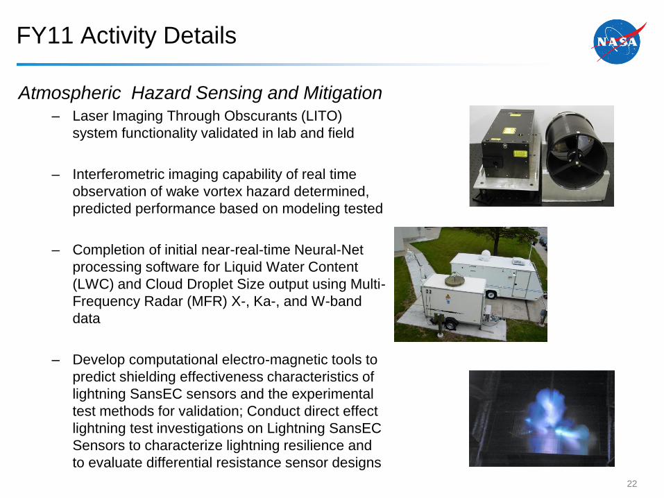
FY11 Activity Details
Atmospheric Hazard Sensing and Mitigation– Laser Imaging Through Obscurants (LITO)
system functionality validated in lab and field
– Interferometric imaging capability of real time
observation of wake vortex hazard determined,
predicted performance based on modeling tested
– Completion of initial near-real-time Neural-Net
processing software for Liquid Water Content
(LWC) and Cloud Droplet Size output using Multi-
Frequency Radar (MFR) X-, Ka-, and W-band
data
– Develop computational electro-magnetic tools to
predict shielding effectiveness characteristics of
lightning SansEC sensors and the experimental
test methods for validation; Conduct direct effect
lightning test investigations on Lightning SansEC
Sensors to characterize lightning resilience and
to evaluate differential resistance sensor designs
22
Q&A
23
Recommended