AUTOMATIC BATTERY CHARGER FOR MOBILE APPLICATION
USING SOLAR PV MODULE
By
ASROY ANGKOI
FINAL YEAR PROJECT II
FINAL REPORT
Submitted to the Department of Electrical & Electronic Engineering
In Partial Fulfillment of the Requirement for the Degree
Bachelor of Engineering (Hons)
(Electrical & Electronics Engineering)
Universiti Teknologi PETRONAS
Bandar Seri Iskandar
31750, Tronoh
Perak Darul Ridzuan
© Copyright 2014
By
Asroy Angkoi
i
CERTIFICATION OF APPROVAL
Automatic Battery Charger for Mobile Application Using Solar Photovoltaic (PV)
Module
by,
Asroy Angkoi
13691
A project dissertation submitted to the
Electrical & Electronic Engineering Programme
Universiti Teknologi PETRONAS
in partial fulfillment of the requirement for
Bachelor of Engineering (Hons)
(Electrical & Electronic)
Approved by,
____________________
(Dr. Nor Zaihar Bin Yahaya)
Universiti Teknologi PETRONAS,
Bandar Seri Iskandar,
31750 Tronoh, Perak.
May 2014

ii
CERTIFICATION OF ORIGINALITY
This is to certify that I am responsible for the work submitted in this project, that the
original work is my own except as specified in the references and acknowledgements,
and the original work contained herein have not been undertaken or done by unspecified
source or persons.
____________________
(Asroy Angkoi)
iii
ABSTRACT
This project aims to upgrade the efficiency and reliability of traditional charging
by introducing an automatic battery charger using solar photovoltaic (PV) module where
light radiation from the sun which is converted into electricity acted as power source and
is harvested through the introduction of a small solar photovoltaic modules. This new
introduction of automatic battery charger emphasizes on automatic charging and
termination in order to ensure the battery is not endangered. This project will be carried
out starting with the grasp of theoretical analysis, then move into the simulation phase
with the aim to identify best circuit design for the project, and lastly the prototype
construction phase. The end result of this project will involve a functional prototype that
will be able to charge a mobile phone when exposed to the sun. The successfulness of
this project will have a huge impact on the mobile application industry and media
interactions businesses.
iv
ACKNOWLEDGEMENT
First and foremost, I would like to convey my greatest gratitude to God for
providing me with great condition, health, and well-being throughout the process of
completing the project successfully. I also would like to express my gratitude to all the
parties that involve in contributing towards project completion neither directly nor
indirectly. Throughout the duration of Final Year Project (FYP), I have learnt a lot and
gain precious experiences that will surely benefit me in the future.
Next, I would like to thank my supervisor, Dr. Nor Zaihar Bin Yahaya for his
advice, endless support and guidance in assisting me in my project. The cooperation
that has been provided has steered me in the right path.
Other than that, I would also like to thank my family who has provide me with
ample of prayers and continues support all the time since the beginning of my five year
journey in UTP.
Not to forget, my appreciation also goes to all my friends whom have given me
their support and time in helping me at any moment throughout the duration of my
journey in UTP.
v
Table of Contents
Certification......................................................................................................................... i
Abstract .............................................................................................................................. ii
Acknowledgement............................................................................................................. iii
List of Figures .................................................................................................................. vii
List of Tables................................................................................................................... viii
Abbreviations .................................................................................................................... ix
Chapter 1:Introduction ....................................................................................................... 1
1.1. Background of Study ..................................................................... 1
1.2. Problem Statement ......................................................................... 3
1.3. Objectives ....................................................................................... 3
1.4. Scope of Study ............................................................................... 4
1.5. Significance of the Project ............................................................. 4
1.6. Feasibility of the Project ................................................................ 5
Chapter 2:Literature Review .............................................................................................. 6
2.1. To understand basic theory ............................................................ 6
2.1.1. Battery Charger for Mobile Application ............................ 6
2.1.2. Automation of Charging Process ....................................... 8
2.1.3. Photovoltaic (PV) System ................................................ 11
2.2. To simulate ................................................................................... 11
2.2.1. Photovoltaic Panel ............................................................ 11
2.2.2. Controller Circuit ............................................................. 12
Chapter 3:Methodology & Project Works ....................................................................... 16
3.1. Research Methodology................................................................. 16
3.2. Gantt Chart ................................................................................... 17
3.3. Key Milestone .............................................................................. 18
3.4. Flowchart ..................................................................................... 19
3.5. Tools & Software ......................................................................... 20
3.6. Proposed Topology ...................................................................... 20
3.7. Preliminary Design....................................................................... 20
3.8. Costing ......................................................................................... 26
vi
Chapter 4:Result & Discussion ........................................................................................ 27
4.1. Result for completed simulation .................................................. 27
4.2. Result for Prototype ..................................................................... 31
Chapter 5:Conclusion & Recommendation ..................................................................... 35
References ........................................................................................................................ 36
Appendices ....................................................................................................................... 37
vii
LIST OF FIGURES
Fig.1: Schematic of automatic battery charger circuit [2] 2
Fig.2: Simplified battery charger block (10) 9
Fig 3: Macro model of LT1529-5 10
Fig 4: Photovoltaic System (12) 11
Fig 5: Photovoltaic Panel equivalent circuit (16) 13
Fig 6: Macro model of LT1529-5911) 14
Fig.7: Key milestones for FYP I 16
Fig 8: Key milestones for FYP II 17
Fig 9: Flowchart of FYP 20
Fig.10: Overall proposed topology block diagram 21
Fig 11: Solar photovoltaic equivalent circuit in LT Spice 22
Fig 12: Controller circuit in LT Spice 24
Fig 13: Output power of circuit in Fig. 11 27
Fig. 14: Voltage and Current output of Fig. 11 28
Fig. 15: Voltage and current output of Fig. 12 29
Fig. 16: Project prototype 31
Fig. 17: Photovoltaic panel performance 32
viii
LIST OF TABLES
Table I: Type of controlled charging [9] 7
Table II: Type of Battery Charger [9] 8
Table III: Summary of literature review 15
Table IV: Methodology and project activities 16
Table V: Gantt chart for FYP 1 & FYP II 17
Table VI: Resistor range in accordance to output level 25
Table VII: Material Specification and Cost 26
Table VIII: Result analysis summary of PV panel 29
Table IX: Result analysis summary of controller circuit 29
Table X: PV panel performance 31
Table XI: Output power from PV panel 33
ix
LIST OF ABBREVIATIONS
BC: Battery charger
PV: Photovoltaic
OTA: Operational transconductance amplifier
FYP I: Final year project I
FYP II: Final year project II
V: Voltage
A: Ampere
AC: Alternating current
DC: Direct current
IC: Integrated circuit
1
CHAPTER 1: INTRODUCTION
In order to fully understand the whole picture and execution of this project, the
introduction is divided into separate sub categories, where firstly the background of
study of this project is detailed out. Next, the problem statement is mentioned and few
objectives are made clear to tackle the problems. To ensure the project does not deviate
from the objectives, scope of study of this project will be elaborated. Significance and
feasibility of the project in term of cost and time will also be discussed in this chapter.
1.1 Background of Study
1.1.1 Automatic Battery Charger
A battery charger is defined as a circuit or a device to put energy into a
rechargeable battery in which is widely used in mobile phone nowadays[1]. Battery
chargers are important in order to make sure those mobile applications stay active
through charging process in a way that power are constantly provided. Traditional
charging involves adapters and dependable charging circuitry. Automation of charging
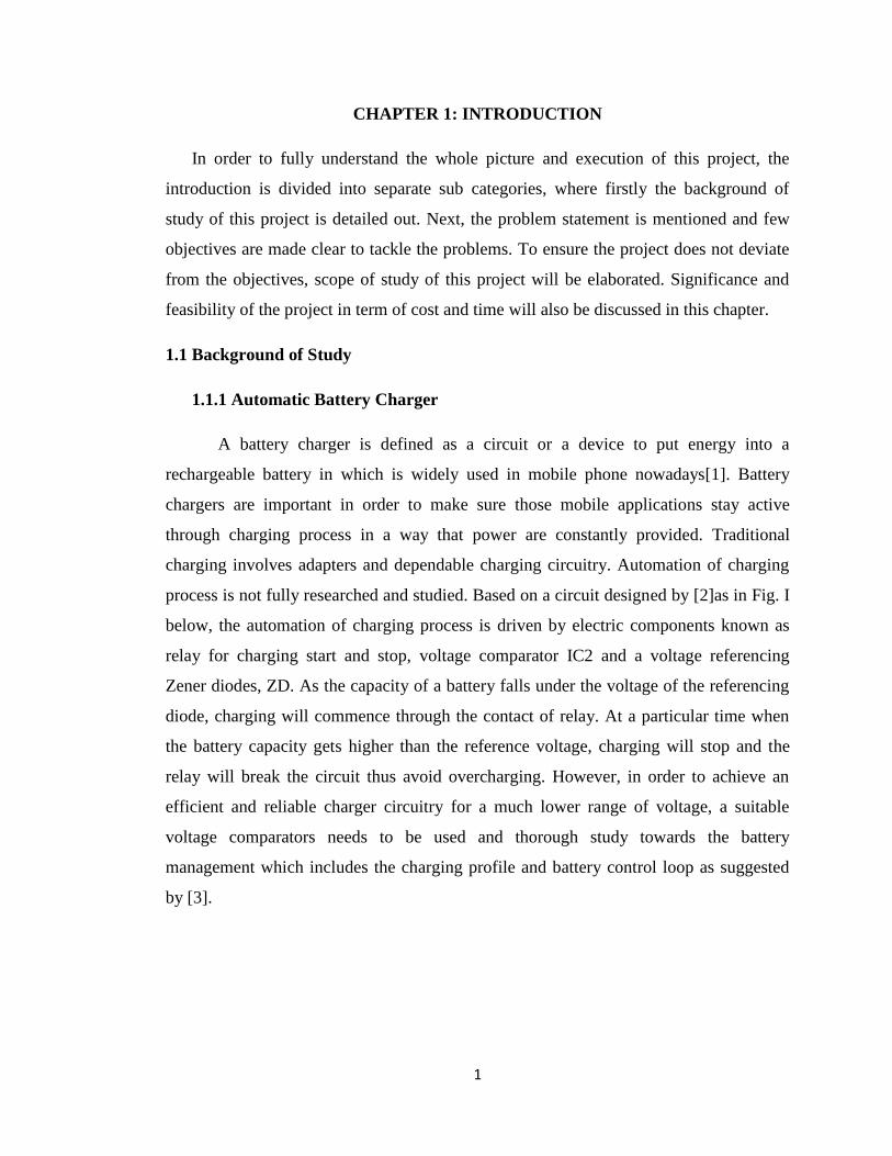
process is not fully researched and studied. Based on a circuit designed by [2]as in Fig. I
below, the automation of charging process is driven by electric components known as
relay for charging start and stop, voltage comparator IC2 and a voltage referencing
Zener diodes, ZD. As the capacity of a battery falls under the voltage of the referencing
diode, charging will commence through the contact of relay. At a particular time when
the battery capacity gets higher than the reference voltage, charging will stop and the
relay will break the circuit thus avoid overcharging. However, in order to achieve an
efficient and reliable charger circuitry for a much lower range of voltage, a suitable
voltage comparators needs to be used and thorough study towards the battery
management which includes the charging profile and battery control loop as suggested
by [3].
2
Fig.1: Schematic of automatic battery charger circuit[2]
1.1.2 Mobile Application
With revolution of technology, the function of mobile application has become
more powerful and very complex. The designs of most mobile applications are compact
and thus not many functions are available due to size consideration. For extra function,
devices will need to have external devices in which raise the dependability on that
particular device. As stated by [4], the mobile application in market attracts impressive
cash flow and success stories and thus the demand for mobile application has greatly
increased. The aim of this project is to focus on mobile applications due to its proven
success stories globally. This project will explore the possibility of integrating a new
function which is automatic charging with PV modules. According to [5], the question
on how far automation is effective in a mobile application is raised. However the study
by [5] only involve preliminary critical analysis on automation and suggested a deeper
and mature study shall be continued in that area.
3
1.1.3 PV Module
This project will explore the design of a photovoltaic (PV) module. A PV
module is a group of PV cells which are electronically grouped to form a pixel and are
connected to DC-DC converter block. The study on PV modules in this project will
concentrate on determining the size of a pixel, configuration of solar cells
(series/parallel), and power electronics circuitry. The main deliverable is to achieve a
high quality output voltage.
1.2 Problem statement
The integration of photovoltaic systems into a battery charger circuit has not
been extensively explored. At this time, only a stand-alone power generation from
photovoltaic system is used. Therefore main challenge is to design an efficient
converter circuit. To achieve this, good selection of photovoltaic modules and materials
must be emphasized. The size of the PV system is also taken into consideration to cut
cost and for user conveniences.
Other than that, other challenge that is encountered is also the reliability and
efficiency of the battery charger circuit itself. Since the charging process is in automatic
mode, suitable electronic component for the circuit design have to be taken into
consideration.
1.3 Objectives
In order to achieve the desired result for the project, few objectives are made clear and
as a benchmark for the progress of the report. The preliminary objectives of the project
are as follows;
1.3.1 To understand:
1.3.1.1 Battery charger for low voltage mobile application
1.3.1.2 Automation of charging process
1.3.1.3 Operation of PV module and selection of PV materials
4
1.3.2 To model and simulate:
1.3.2.1 PV charger
1.3.2.2 Charging profile
1.3.3 To design and validate an automatic PV charger prototype
1.4 Scope of study
The main of this project is to design and validate a battery charger resulting from the
integration of photovoltaic modules with a controller circuit. This project will focus on
extra low voltage application where the voltage range used in the project is below
120V[6] specifically a mobile phone which voltage ranging from 3.7V to 4.5V and
current characteristic from 1A to 2A. Thus the selection of PV materials which act as
power source in this project is very important. Detail understanding of the rated output
power, voltage, and current will is crucial. In addition, details understanding of PV
system will aid in the materials selection and size decision.
Since the final objective of this project involve a prototype fabrication, multiple
simulations using LT Spice V4.2, MATLAB V7.12, and lab experimental works will be
carried out in order to understand and come out with the most efficient and reliable PV
charger circuit design. Based on data obtained in each simulation and experiment,
conclusion on the relationship of the integration can be determined and thus on its final
stage, a functional prototype is achieved.
1.5 Significance of the project
Common known charging involves a frequent unplugging mechanism from
power adapter and through the use of external devices such as power banks. It can be
considered as the traditional way to charge and make sure a mobile application stays
active for routine usage that serves many purposes. Looking forward into the future, it is
very significant to resolve limited battery lifetime problem especially when the world
engages into intensive multimedia services. Thus, this project will look into the
possibility of solar photovoltaic (PV) module in generating a small circuitry to be
embedded into a battery charger of an application. In addition, the project also aims to
5
cut users’ dependability on charging the mobile application for example through
adapters and power banks. Hence, the successfulness of this project will indirectly give a
boost and lift up the mobile applications industry.
1.5 Feasibility of the project
15.1 Timeframe
The project will involve simulations and the fabrication of a prototype. The time
frame allocated for this project which is two semesters is feasible to complete the
project. The final outcome of this project will be a construction of a prototype and this
will be achieved in FYP 2 which falls on August 2014. During FYP 1, the focus will
mainly to perform simulation and analyze the data obtained and acquisition of materials.
During FYP 2 on the other hand, the focus will shift to construct and troubleshoot the
prototype.
15.2 Cost
The fabrication of prototype for this project will incorporate a small in size solar
panel and few electronic components. Some of the electronic components are provided
within the department’s facility. Thus, it is feasible to conduct the project within the
allocation of budget by the department.
6
CHAPTER 2: LITERATURE REVIEW & THEORY
Due to vast development in the information and manufacturing technologies,
performances of portable gadgets and mobile applications are greatly enhanced. Power
requirement and consumption of these gadgets therefore also increase. These
applications are normally equipped with rechargeable batteries due to its cost efficiency
over its lifetime. However, due to the great power consumption, users have to deal with
limited battery lifetime through routine task called human-battery interaction[7].This
will eventually impair the user to communicate, perform works, share ideas, and interact
effectively. Survey has been conducted all over and showed that majority of the user
demand increase in their battery lifetime. Over the years, significance research and
approach are explored to improve the battery lifetime. Thus, in this chapter, journals,
books and research papers are referred to conduct a literature review for the details of
the project. The literature review are divided based on the objectives outlined earlier in
the report.
2.1 To understand basic theory and fundamentals of the project (Objective 1)
In this section, the fundamental concept of battery chargers, automation of charging
process and operation of PV modules is studied and understood.
2.1.1 Battery charger for low voltage application
In any portable products, battery charger (BC) and any charging circuitry play an
important in keeping devices stay active when needed especially when it comes down to
interactive multimedia services nowadays. BC is a device that is used to apply energy
into a rechargeable battery through current flow. A BC is made up materials that include
a plate and a cell. The plate in the charger will draw a charge when direct current flow
through it, and then eventually produces certain amount of electric current[8].A
conventional BC is able to charge only one type of battery. However, in a research by
[9], he introduces a BC that able to accept wide range of input and supply wide range of
voltage for any portable application. As stated in the scope of study, the project will
focus on extra low voltage application which is below 120V. The power for the charging
is fed by various power sources which can be summarize in Table I.
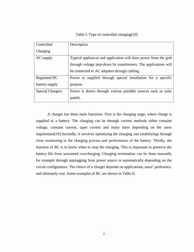
7
Table I: Type of controlled charging[10]
Controlled
Charging
Description
AC supply Typical appliances and application will draw power from the grid
through voltage step-down by transformers. The applications will
be connected to AC adapters through cabling.
Regulated DC
battery supply
Power is supplied through special installation for a specific
purpose.
Special Chargers Power is drawn through various portable sources such as solar
panels.
A charger has three main functions. First is the charging stage, where charge is
supplied to a battery. The charging can be through various methods either constant
voltage, constant current, taper current and many more depending on the users
requirement[10].Secondly, it involves optimizing the charging rate (stabilizing) through
close monitoring to the charging process and performance of the battery. Thirdly, the
function of BC is to know when to stop the charging. This is important to preserve the
battery life from unwanted overcharging. Charging termination can be done manually
for example through unplugging from power source or automatically depending on the
circuit configuration. The choice of a charger depends on applications, users’ preference,
and ultimately cost. Some examples of BC are shown in Table II.
8
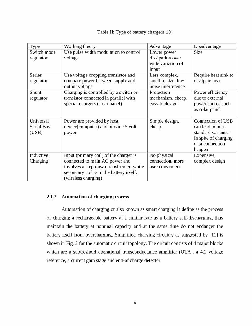
Table II: Type of battery chargers[10]
2.1.2 Automation of charging process
Automation of charging or also known as smart charging is define as the process
of charging a rechargeable battery at a similar rate as a battery self-discharging, thus
maintain the battery at nominal capacity and at the same time do not endanger the
battery itself from overcharging. Simplified charging circuitry as suggested by [11] is
shown in Fig. 2 for the automatic circuit topology. The circuit consists of 4 major blocks
which are a subtreshold operational transconductance amplifier (OTA), a 4.2 voltage
reference, a current gain stage and end-of charge detector.
Type Working theory Advantage Disadvantage
Switch mode
regulator
Use pulse width modulation to control
voltage
Lower power
dissipation over
wide variation of
input
Size
Series
regulator
Use voltage dropping transistor and
compare power between supply and
output voltage
Less complex,
small in size, low
noise interference
Require heat sink to
dissipate heat
Shunt
regulator
Charging is controlled by a switch or
transistor connected in parallel with
special chargers (solar panel)
Protection
mechanism, cheap,
easy to design
Power efficiency
due to external
power source such
as solar panel
Universal
Serial Bus
(USB)
Power are provided by host
device(computer) and provide 5 volt
power
Simple design,
cheap.
Connection of USB
can lead to non-
standard variants.
In spite of charging,
data connection
happen
Inductive
Charging
Input (primary coil) of the charger is
connected to main AC power and
involves a step-down transformer, while
secondary coil is in the battery itself.
(wireless charging)
No physical
connection, more
user convenient
Expensive,
complex design
9
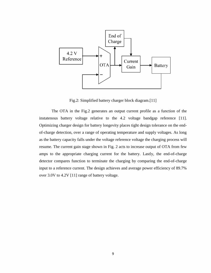
Fig.2: Simplified battery charger block diagram.[11]
The OTA in the Fig.2 generates an output current profile as a function of the
instatenous battery voltage relative to the 4.2 voltage bandgap reference [11].
Optimizing charger design for battery longevity places tight design tolerance on the end-
of-charge detection, over a range of operating temperature and supply voltages. As long
as the battery capacity falls under the voltage reference voltage the charging process will
resume. The current gain stage shown in Fig. 2 acts to increase output of OTA from few
amps to the appropriate charging current for the battery. Lastly, the end-of-charge
detector compares function to terminate the charging by comparing the end-of-charge
input to a reference current. The design achieves and average power efficiency of 89.7%
over 3.0V to 4.2V [11] range of battery voltage.
10
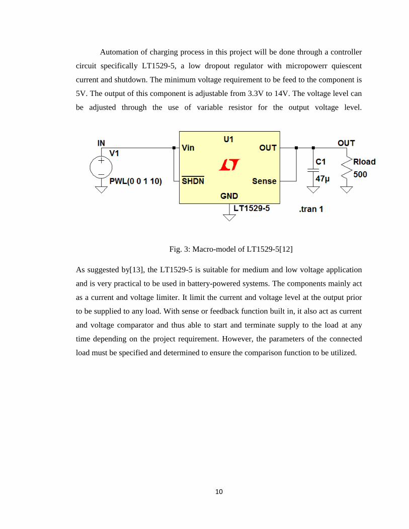
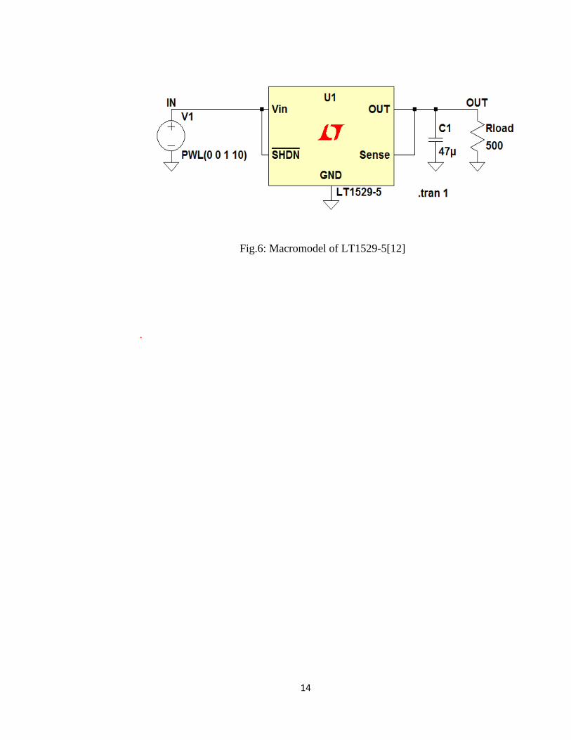
Automation of charging process in this project will be done through a controller
circuit specifically LT1529-5, a low dropout regulator with micropowerr quiescent
current and shutdown. The minimum voltage requirement to be feed to the component is
5V. The output of this component is adjustable from 3.3V to 14V. The voltage level can
be adjusted through the use of variable resistor for the output voltage level.
Fig. 3: Macro-model of LT1529-5[12]
As suggested by[13], the LT1529-5 is suitable for medium and low voltage application
and is very practical to be used in battery-powered systems. The components mainly act
as a current and voltage limiter. It limit the current and voltage level at the output prior
to be supplied to any load. With sense or feedback function built in, it also act as current
and voltage comparator and thus able to start and terminate supply to the load at any
time depending on the project requirement. However, the parameters of the connected
load must be specified and determined to ensure the comparison function to be utilized.
11
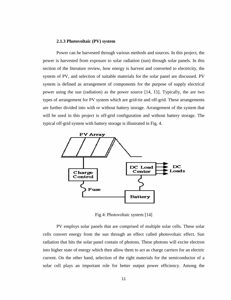
2.1.3 Photovoltaic (PV) system
Power can be harvested through various methods and sources. In this project, the
power is harvested from exposure to solar radiation (sun) through solar panels. In this
section of the literature review, how energy is harvest and converted to electricity, the
system of PV, and selection of suitable materials for the solar panel are discussed. PV
system is defined as arrangement of components for the purpose of supply electrical
power using the sun (radiation) as the power source [14, 15]. Typically, the are two
types of arrangement for PV system which are grid-tie and off-grid. These arrangements
are further divided into with or without battery storage. Arrangement of the system that
will be used in this project is off-grid configuration and without battery storage. The
typical off-grid system with battery storage is illustrated in Fig. 4.
Fig 4: Photovoltaic system [14]
PV employs solar panels that are comprised of multiple solar cells. These solar
cells convert energy from the sun through an effect called photovoltaic effect. Sun
radiation that hits the solar panel contain of photons. These photons will excite electron
into higher state of energy which then allow them to act as charge carriers for an electric
current. On the other hand, selection of the right materials for the semiconductor of a
solar cell plays an important role for better output power efficiency. Among the
12
materials are monocrystalline silicon, amorphous silicon, and many more. However,
taking into consideration of cost, amorphous silicon is choose for the prototype
fabrication. For a small circuitry project, the amorphous silicon materials will suit the
requirement of the project.
According to [16], a design with a low-cost, compact and feasible and power
efficient is proposed. The proposal includes a battery protection controller design in
which a power comparator component will connect and disconnect the solar panel from
the charging circuit when the desired battery capacity is achieved. This feature protects
the rechargeable battery from the adverse overcharging and undercharging. The
limitation to the proposal is that the overall concept only applies during a consistent
solar radiation which is during sunny day and luminance of approximately 50,000 lux
[17]. This limitation is however addressed by [17] where they conducted experiments on
solar cell efficiency under the indoor where the average luminance ranges from 100 to
1,000 lux [17] . The result of their experiments varies with the lighting condition. With a
halogen light, the solar panel can generate energy in the amount of 1/3 of the ordinary
battery and this can support minimal to moderate use of an application, while under
normal fluorescent lighting, the solar panel generate energy only 1/20 of the ordinary
battery which is too small to produce a meaningful amount of power to a mobile
application.
2.2 To model and stimulate (Objective 2)
Through a solid understanding on the fundamentals of the project scope, the circuitry
of the project is being constructed and simulated through simulation software which will
be discussed further in this section. The main aim of this section is to come with a
successful simulation that is able to meet the expected outcome of this project.
2.2.1 Photovoltaic (PV) panel
PV system requirement used in this project will not be very complex since the
required power and voltage level is very small. Thus charger controller and battery
storage will not be needed. Prior to material acquisition for the prototype construction,
the performance of the PV panel need to be evaluated in order to select the best PV
13
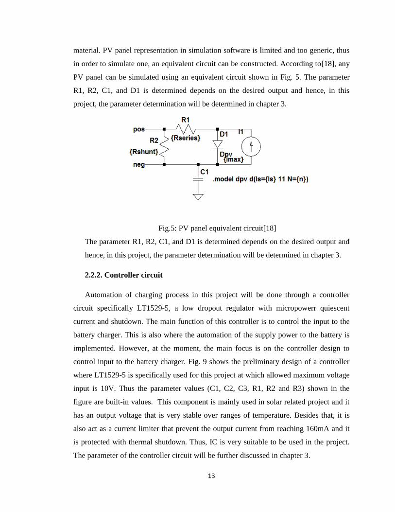
material. PV panel representation in simulation software is limited and too generic, thus
in order to simulate one, an equivalent circuit can be constructed. According to[18], any
PV panel can be simulated using an equivalent circuit shown in Fig. 5. The parameter
R1, R2, C1, and D1 is determined depends on the desired output and hence, in this
project, the parameter determination will be determined in chapter 3.
Fig.5: PV panel equivalent circuit[18]
The parameter R1, R2, C1, and D1 is determined depends on the desired output and
hence, in this project, the parameter determination will be determined in chapter 3.
2.2.2. Controller circuit
Automation of charging process in this project will be done through a controller
circuit specifically LT1529-5, a low dropout regulator with micropowerr quiescent
current and shutdown. The main function of this controller is to control the input to the
battery charger. This is also where the automation of the supply power to the battery is
implemented. However, at the moment, the main focus is on the controller design to
control input to the battery charger. Fig. 9 shows the preliminary design of a controller
where LT1529-5 is specifically used for this project at which allowed maximum voltage
input is 10V. Thus the parameter values (C1, C2, C3, R1, R2 and R3) shown in the
figure are built-in values. This component is mainly used in solar related project and it
has an output voltage that is very stable over ranges of temperature. Besides that, it is
also act as a current limiter that prevent the output current from reaching 160mA and it
is protected with thermal shutdown. Thus, IC is very suitable to be used in the project.
The parameter of the controller circuit will be further discussed in chapter 3.
14
Fig.6: Macromodel of LT1529-5[12]
.
15
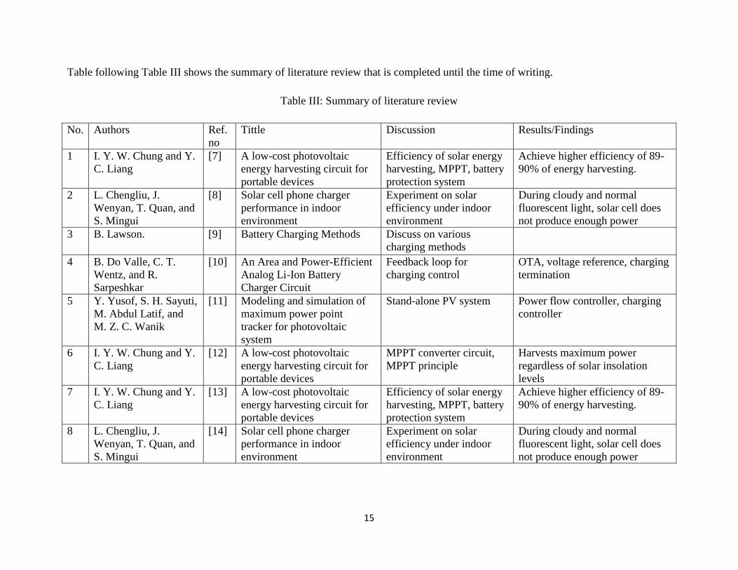
Table following Table III shows the summary of literature review that is completed until the time of writing.
Table III: Summary of literature review
No. Authors Ref.
no
Tittle Discussion Results/Findings
1 I. Y. W. Chung and Y.
C. Liang
[7] A low-cost photovoltaic
energy harvesting circuit for
portable devices
Efficiency of solar energy
harvesting, MPPT, battery
protection system
Achieve higher efficiency of 89-
90% of energy harvesting.
2 L. Chengliu, J.
Wenyan, T. Quan, and
S. Mingui
[8] Solar cell phone charger
performance in indoor
environment
Experiment on solar
efficiency under indoor
environment
During cloudy and normal
fluorescent light, solar cell does
not produce enough power
3 B. Lawson. [9] Battery Charging Methods Discuss on various
charging methods
4 B. Do Valle, C. T.
Wentz, and R.
Sarpeshkar
[10] An Area and Power-Efficient
Analog Li-Ion Battery
Charger Circuit
Feedback loop for
charging control
OTA, voltage reference, charging
termination
5 Y. Yusof, S. H. Sayuti,
M. Abdul Latif, and
M. Z. C. Wanik
[11] Modeling and simulation of
maximum power point
tracker for photovoltaic
system
Stand-alone PV system Power flow controller, charging
controller
6 I. Y. W. Chung and Y.
C. Liang
[12] A low-cost photovoltaic
energy harvesting circuit for
portable devices
MPPT converter circuit,
MPPT principle
Harvests maximum power
regardless of solar insolation
levels
7 I. Y. W. Chung and Y.
C. Liang
[13] A low-cost photovoltaic
energy harvesting circuit for
portable devices
Efficiency of solar energy
harvesting, MPPT, battery
protection system
Achieve higher efficiency of 89-
90% of energy harvesting.
8 L. Chengliu, J.
Wenyan, T. Quan, and
S. Mingui
[14] Solar cell phone charger
performance in indoor
environment
Experiment on solar
efficiency under indoor
environment
During cloudy and normal
fluorescent light, solar cell does
not produce enough power
16
CHAPTER 3: METHODOLOGY & PROJECT WORK
This section will elaborate more on the methods and procedures used in this project to
achieve the objectives of this project.
3.1 Research Methodology
Table IV shows the project activities that are covered in this project.
Table IV: Methodology and project activities
Objective(s) Methodology Project activities
Objective 1. Research and extensive
literature review
Research are carried out to understand how
battery charger and solar photovoltaic
works. Literature review is to relate this
project with previous works and researches
done through variety of references.
Extended proposal writing
and defense
Background, objectives, and problem
statement are stated concisely and clearly.
The scope of study for the project must be
relevant and the project is feasible to be
carried out with specified duration of two
semesters.
Objective 2. Experimental design Circuit is designed for simulation stage
through detail mathematical calculations
and thorough technical interpretation.
Simulation Simulations are carried by using Proteus
simulator, Pspice, and MATLAB. The
results of each simulation are gathered and
analyzed.
Design improvement and
modification
If data gathered from the simulation does
not meet the project requirement,
modification and improvement are made to
the design and simulation is carried out
again. The process is repeated until
satisfactory results are obtained.
Objective 3. Prototype fabrication Upon multiple simulations and when
satisfactory result is obtained, fabrication
of the prototype for will start.
17
3.2 Gantt chart
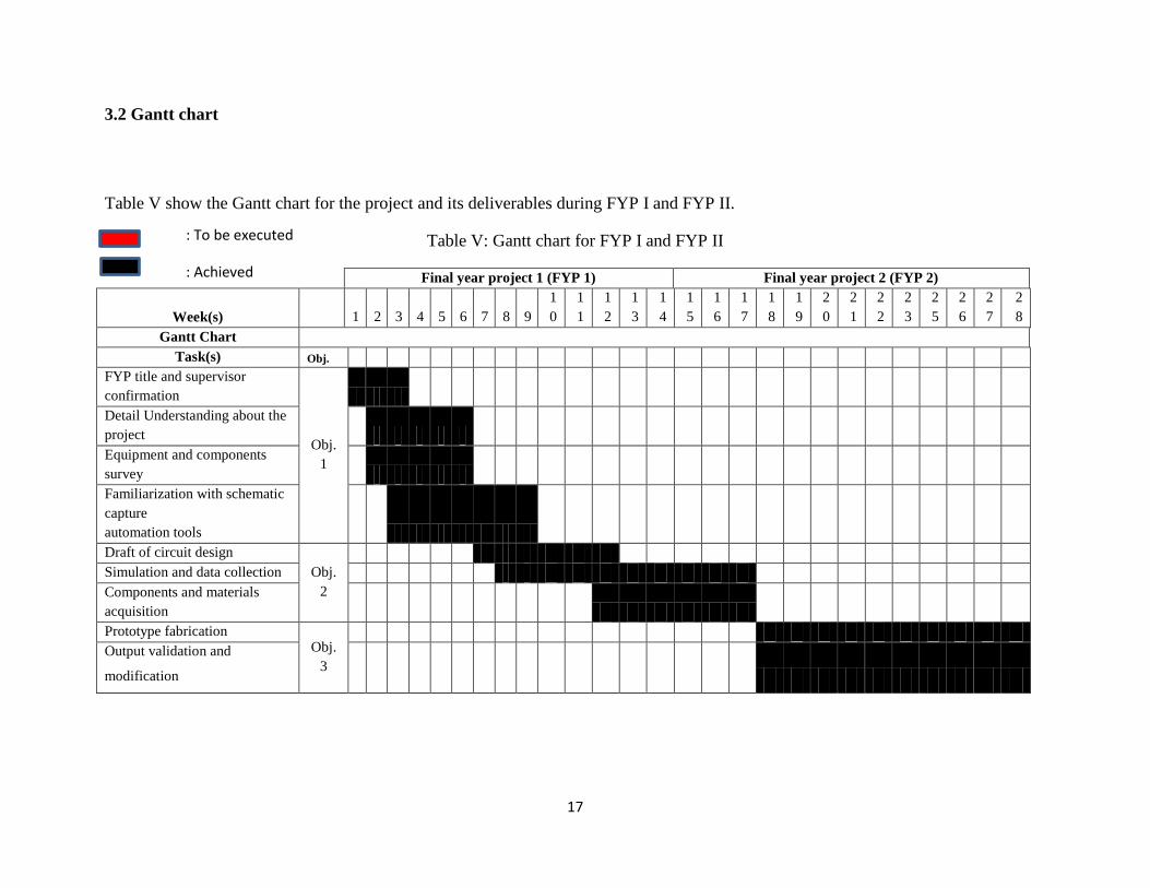
Table V show the Gantt chart for the project and its deliverables during FYP I and FYP II.
Table V: Gantt chart for FYP I and FYP II
Final year project 1 (FYP 1) Final year project 2 (FYP 2)
Week(s) 1 2 3 4 5 6 7 8 9
1
0
1
1
1
2
1
3
1
4
1
5
1
6
1
7
1
8
1
9
2
0
2
1
2
2
2
3
2
5
2
6
2
7
2
8
Gantt Chart
Task(s) Obj.
FYP title and supervisor
confirmation
Obj.
1
Detail Understanding about the
project
Equipment and components
survey
Familiarization with schematic
capture
automation tools
Draft of circuit design
Obj.
2
Simulation and data collection
Components and materials
acquisition
Prototype fabrication Obj.
3
Output validation and
modification
: To be executed
: Achieved
18
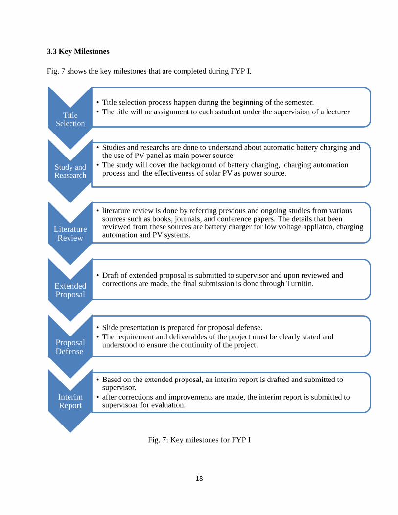
3.3 Key Milestones
Fig. 7 shows the key milestones that are completed during FYP I.
Fig. 7: Key milestones for FYP I
Title Selection
• Title selection process happen during the beginning of the semester.
• The title will ne assignment to each sstudent under the supervision of a lecturer
Study and Reasearch
• Studies and researchs are done to understand about automatic battery charging and the use of PV panel as main power source.
• The study will cover the background of battery charging, charging automation process and the effectiveness of solar PV as power source.
Literature Review
• literature review is done by referring previous and ongoing studies from various sources such as books, journals, and conference papers. The details that been reviewed from these sources are battery charger for low voltage appliaton, charging automation and PV systems.
Extended Proposal
• Draft of extended proposal is submitted to supervisor and upon reviewed and corrections are made, the final submission is done through Turnitin.
Proposal Defense
• Slide presentation is prepared for proposal defense.
• The requirement and deliverables of the project must be clearly stated and understood to ensure the continuity of the project.
Interim Report
• Based on the extended proposal, an interim report is drafted and submitted to supervisor.
• after corrections and improvements are made, the interim report is submitted to supervisoar for evaluation.
19
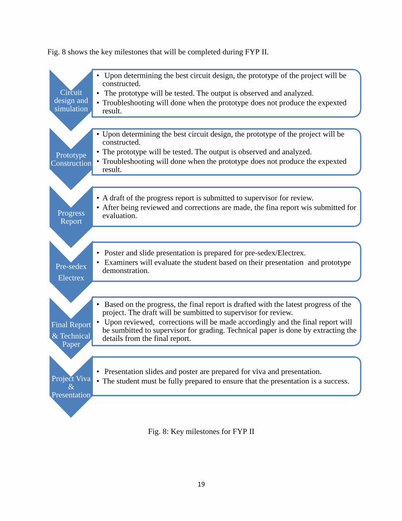
Fig. 8 shows the key milestones that will be completed during FYP II.
Fig. 8: Key milestones for FYP II
Circuit design and simulation
• Upon determining the best circuit design, the prototype of the project will be constructed.
• The prototype will be tested. The output is observed and analyzed.
• Troubleshooting will done when the prototype does not produce the expexted result.
Prototype Construction
• Upon determining the best circuit design, the prototype of the project will be constructed.
• The prototype will be tested. The output is observed and analyzed.
• Troubleshooting will done when the prototype does not produce the expexted result.
Progress Report
• A draft of the progress report is submitted to supervisor for review.
• After being reviewed and corrections are made, the fina report wis submitted for evaluation.
Pre-sedex
Electrex
• Poster and slide presentation is prepared for pre-sedex/Electrex.
• Examiners will evaluate the student based on their presentation and prototype demonstration.
Final Report
& Technical Paper
• Based on the progress, the final report is drafted with the latest progress of the project. The draft will be sumbitted to supervisor for review.
• Upon reviewed, corrections will be made accordingly and the final report will be sumbitted to supervisor for grading. Technical paper is done by extracting the details from the final report.
Project Viva &
Presentation
• Presentation slides and poster are prepared for viva and presentation.
• The student must be fully prepared to ensure that the presentation is a success.
20
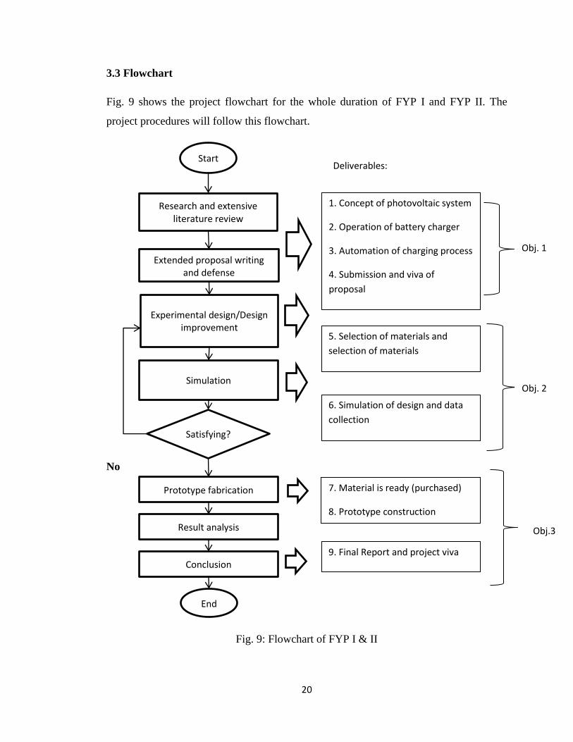
3.3 Flowchart
Fig. 9 shows the project flowchart for the whole duration of FYP I and FYP II. The
project procedures will follow this flowchart.
No
Yes
Fig. 9: Flowchart of FYP I & II
Start
Research and extensive literature review
Extended proposal writing and defense
Experimental design/Design improvement
Simulation
Satisfying?
Prototype fabrication
Result analysis
Conclusion
End
1. Concept of photovoltaic system
2. Operation of battery charger
3. Automation of charging process
4. Submission and viva of
proposal
5. Selection of materials and
selection of materials
6. Simulation of design and data
collection
7. Material is ready (purchased)
8. Prototype construction
9. Final Report and project viva
Deliverables:
Obj. 1
Obj. 2
Obj.3
21
3.5 Tool & Software required
Tools and software that required throughout the implementation of this are:
1. Personal computer/ Laptop
2. Digital multi-meter
3. Proteus simulator 8
4. LT Spice Version V4.2
5. MATLAB V7.12
6. Pspice
7. Microsoft office 2010 tools (Excel & Word)
8. Electronic components (capacitors, resistors, voltage regulators, ICs)
3.6 Proposed topology
To complete this project, a set of procedures is drafted to obtain the required
output and requirement of this project. The procedures is concluded and illustrated in
Fig. 10.
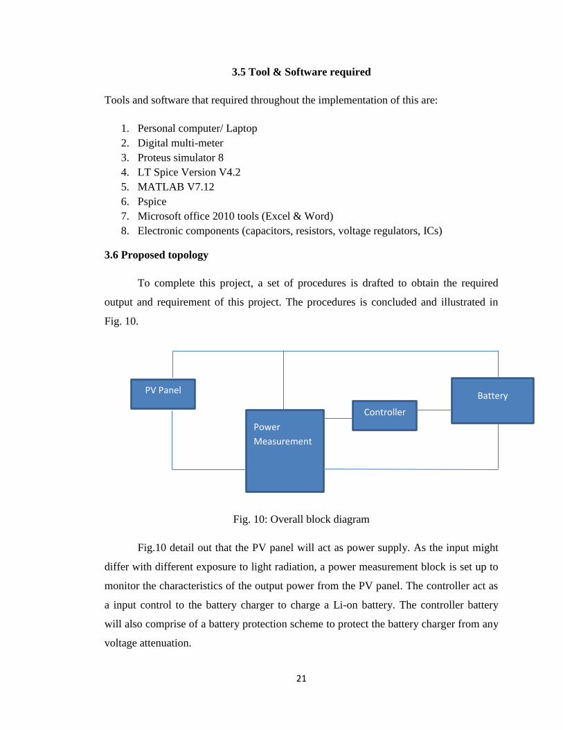
Fig. 10: Overall block diagram
Fig.10 detail out that the PV panel will act as power supply. As the input might
differ with different exposure to light radiation, a power measurement block is set up to
monitor the characteristics of the output power from the PV panel. The controller act as
a input control to the battery charger to charge a Li-on battery. The controller battery
will also comprise of a battery protection scheme to protect the battery charger from any
voltage attenuation.
PV Panel
Power
Measurement
Controller
Battery
22
3.7 Preliminary design
In this section, the main elements of the project which are PV panel, controller circuit,
and battery representation is treated individually to determine the respective parameters
prior to prototype construction. After determining the parameters, the circuit is then
simulated in LT Spice V4.2 to evaluate and analyze the performance.
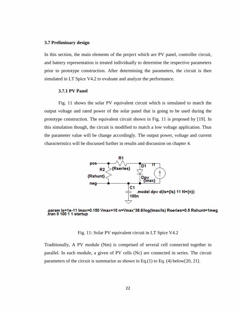
3.7.1 PV Panel
Fig. 11 shows the solar PV equivalent circuit which is simulated to match the
output voltage and rated power of the solar panel that is going to be used during the
prototype construction. The equivalent circuit shown in Fig. 11 is proposed by [19]. In
this simulation though, the circuit is modified to match a low voltage application. Thus
the parameter value will be change accordingly. The output power, voltage and current
characteristics will be discussed further in results and discussion on chapter 4.
Fig. 11: Solar PV equivalent circuit in LT Spice V4.2
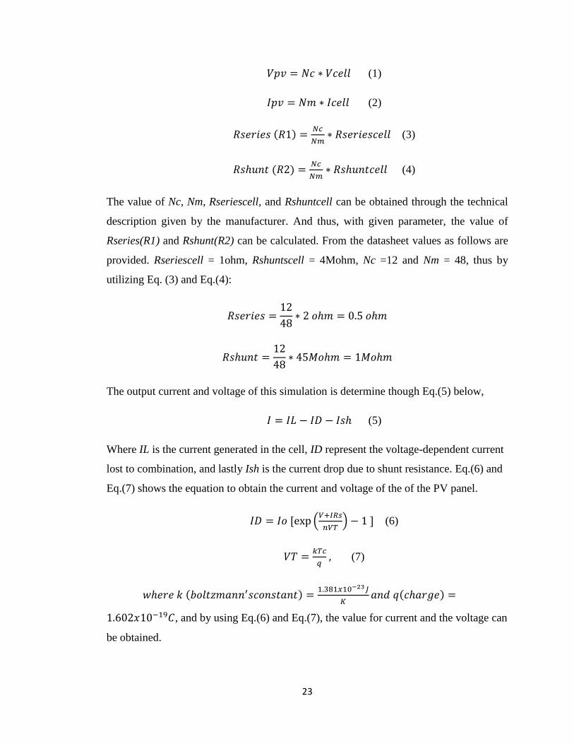
Traditionally, A PV module (Nm) is comprised of several cell connected together in
parallel. In each module, a given of PV cells (Nc) are connected in series. The circuit
parameters of the circuit is summarize as shown in Eq.(1) to Eq. (4) below[20, 21].
23
(1)
(2)
( )
(3)
( )
(4)
The value of Nc, Nm, Rseriescell, and Rshuntcell can be obtained through the technical
description given by the manufacturer. And thus, with given parameter, the value of
Rseries(R1) and Rshunt(R2) can be calculated. From the datasheet values as follows are
provided. Rseriescell = 1ohm, Rshuntscell = 4Mohm, Nc =12 and Nm = 48, thus by
utilizing Eq. (3) and Eq.(4):
The output current and voltage of this simulation is determine though Eq.(5) below,
(5)
Where IL is the current generated in the cell, ID represent the voltage-dependent current
lost to combination, and lastly Ish is the current drop due to shunt resistance. Eq.(6) and
Eq.(7) shows the equation to obtain the current and voltage of the of the PV panel.
(
) (6)
(7)
( )
( )
, and by using Eq.(6) and Eq.(7), the value for current and the voltage can
be obtained.
24
( )
From the value of current and thermal voltage of the solar, the output voltage of the solar
PV can be calculated using the formula below:
(
)
( ( ))
( )
The calculated (ideal) value of current and voltage are slightly different from the
simulated value. However such difference is to be expected since the internal resistance
of components in the circuit is neglected.
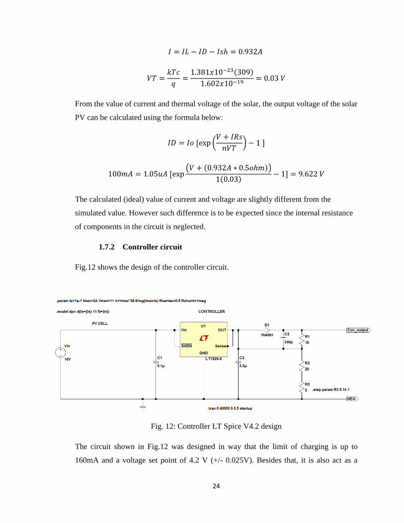
1.7.2 Controller circuit
Fig.12 shows the design of the controller circuit.
Fig. 12: Controller LT Spice V4.2 design
The circuit shown in Fig.12 was designed in way that the limit of charging is up to
160mA and a voltage set point of 4.2 V (+/- 0.025V). Besides that, it is also act as a
25
current limiter that prevent the output current from reaching 160mA and it is protected
with thermal shutdown. The input power source of the circuit (V1) as shown above is
supply from solar PV which is discussed earlier. The output voltage of 3.7V of this
circuit which is denoted at V2 is set through the resistor values shown in Fig. 9 where
R1 = 10ohm, R2 = 20ohm and R3 = 5ohm. The resistor values can be identified using
the formula V=IR. At the controller, the output voltage will vary from 4-6.5V. Table VI
shows the resistors values in accordance to different level of output voltage.
Table VI: Resistor range in accordance to output voltage level
Voltage values (V) Resistor values (ohm)
3.7 34
4 42
5 50
Thus, R1 and R2 value is keep fixed at 10 and 20 ohm respectively. R3 values varied
accordingly, thus a variable resistor is used for R3.
A diode (D1) is set to ensure there is no backflow of current when input power source is
removed or when the battery is at maximum which can act as a power source too.
26
3.8 Costing
The Table VII summarizes materials acquisition and the costing. These are the materials
that are required to fabricate the project prototype which will commence in semester 2.
The item specifications are obtained from: RS Malaysia, Elements14, MyDuino, and
Lelong.com
Table VII: Material specification and cost
Item(s) Description Price
(RM)
Quantity Total
Solar Panel Cytron technology
12V, 833.3mA
38.90 1 RM38.90
Resistor Metal film type
10ohm-10Kohm
0.15
(per
10)
20 RM0.30
Breadboard Breadboard Prototyping Board
-39 x 173 x 9mm
43.37 1 RM43.47
Voltage
regulator
Low Dropout Voltage Regulator,
0.1A, 5V
(LP2951/LT1529-5) ±3.8%, 3-Pin TO-
220
Status: Awaiting delivery
4.89 2 RM9.78
Low Dropout Voltage Regulator,
Adjustable 5A, 1.25 to 28.5V, 3-Pin
TO-3P
49.22 1 RM49.22
Capacitor Aluminium Electrolytic Capacitor
Status: Available
2.46 3 RM7.38
Nokia
1200
Li-Ion 800 mAh battery (BL-5CB)
108.00 1 RM108.00
Total RM257.05
27
CHAPTER 4: RESULTS & DISCUSSION
During the period of FYP 1 and early period of FYP 2, a preliminary circuit design has
been constructed in LT Spice V simulation tool and multiple simulations has been
carried out since to ensure that the project progress is right on track before proceeding to
the construction of the prototype. A complete circuit design and further recommendation
will be detailed out towards the end of FYP 2. Referring to Gantt chart discussed in the
earlier in the project work and methodology, some of the milestone has and objective
has have been achieved. In this chapter, the results are discussed for the simulation and
the prototype itself.
4.1. Result for completed simulation
4.1.1. PV simulated circuit
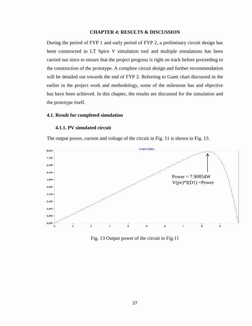
The output power, current and voltage of the circuit in Fig. 11 is shown in Fig. 13.
Fig. 13 Output power of the circuit in Fig.11
Power = 7.90854W
V(pv)*I(D1) =Power
28
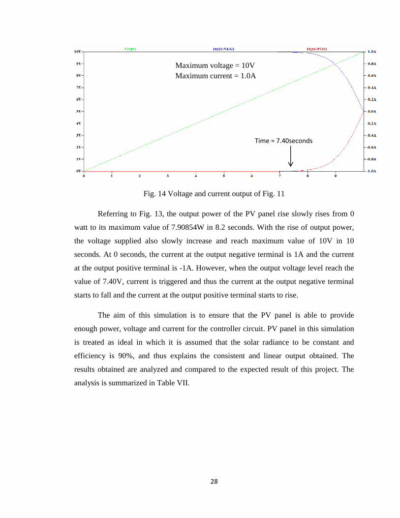
Fig. 14 Voltage and current output of Fig. 11
Referring to Fig. 13, the output power of the PV panel rise slowly rises from 0
watt to its maximum value of 7.90854W in 8.2 seconds. With the rise of output power,
the voltage supplied also slowly increase and reach maximum value of 10V in 10
seconds. At 0 seconds, the current at the output negative terminal is 1A and the current
at the output positive terminal is -1A. However, when the output voltage level reach the
value of 7.40V, current is triggered and thus the current at the output negative terminal
starts to fall and the current at the output positive terminal starts to rise.
The aim of this simulation is to ensure that the PV panel is able to provide
enough power, voltage and current for the controller circuit. PV panel in this simulation
is treated as ideal in which it is assumed that the solar radiance to be constant and
efficiency is 90%, and thus explains the consistent and linear output obtained. The
results obtained are analyzed and compared to the expected result of this project. The
analysis is summarized in Table VII.
Maximum voltage = 10V
Maximum current = 1.0A
Time = 7.40seconds
29
Table VIII: Result analysis summary of PV panel
Simulated result Output requirement Difference Way forwards
Voltage = 10V 5-10V 0% The voltage and current
characteristics of PV
panel is fulfilled.
Current = 1A 1-2A 0%
Power = 7.90854W 10W 20.91% Acceptable output.
Based on the analysis summary, the expected result of output voltage and current level
of the PV panel is fulfilled. However, the power delivered by the PV panel is at
7.90854W in which it differs 20.91% from the expected result of the project. This is due
to thermal and physical resistance that are neglected when the simulation is carried out.
4.1.2. Controller simulation
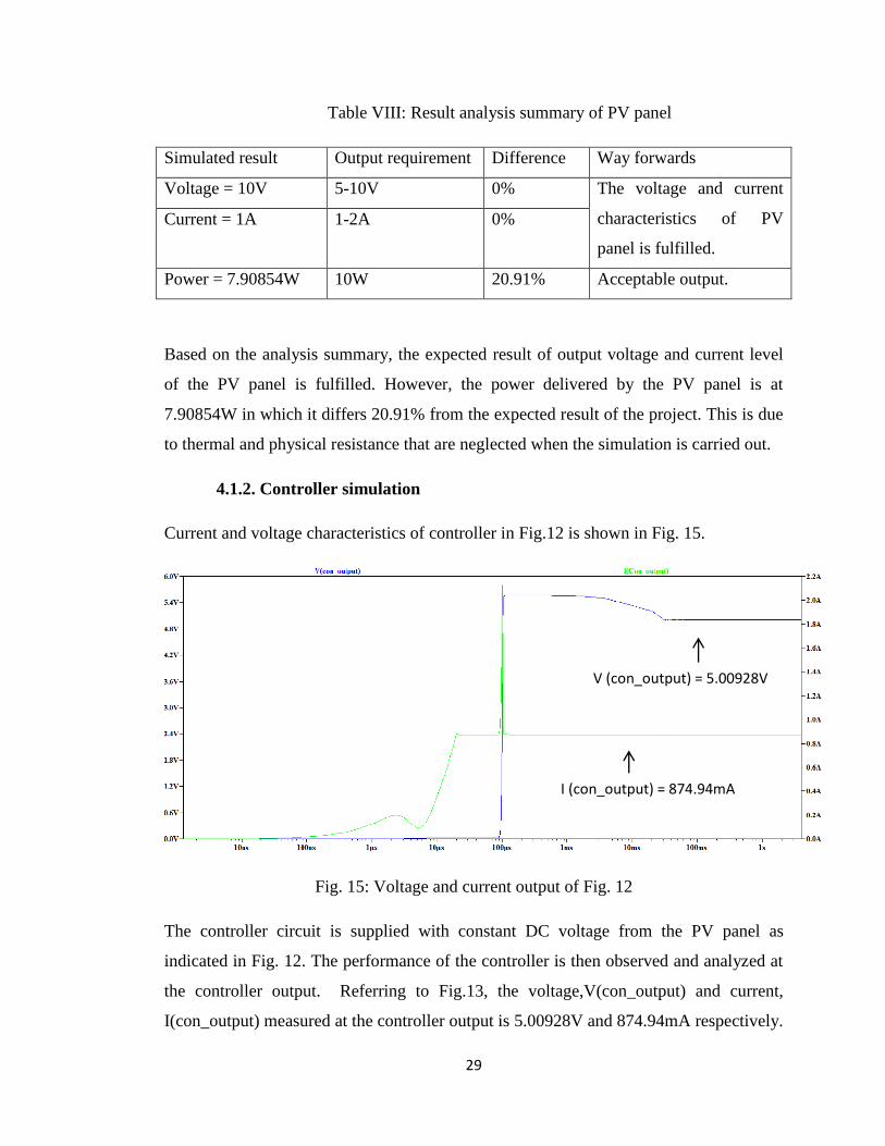
Current and voltage characteristics of controller in Fig.12 is shown in Fig. 15.
Fig. 15: Voltage and current output of Fig. 12
The controller circuit is supplied with constant DC voltage from the PV panel as
indicated in Fig. 12. The performance of the controller is then observed and analyzed at
the controller output. Referring to Fig.13, the voltage,V(con_output) and current,
I(con_output) measured at the controller output is 5.00928V and 874.94mA respectively.
I (con_output) = 874.94mA
V (con_output) = 5.00928V
30
The output is obtained during the duration of 10s of the simulation. The voltage and
current is observed almost instantaneously which is at 100ns.
The aim of this simulation to show that the controller is able to draw suitable current and
voltage level from the PV panel. As observed during the simulation, the results are
favorable when compared to the output requirement of the project. The summary of the
analysis is summarized in Table IX.
Table IX: Result analysis summary of controller circuit
Simulation result Output requirement Way forward/comment
Source (voltage) = 10V 10V The supplied voltage is fulfilled.
Controller output voltage
= 5.00928V
3.7V-5V Output voltage and current fall
within the range of the expected
output requirement. Thus the
controller circuit design in Fig.9 is
chosen as the best circuit design.
Controller output current
=874.94mA
0.8A-2A
It can be concluded that the controller circuit simulation is able to produce the expected
result by using the IC LT1529-5.
31
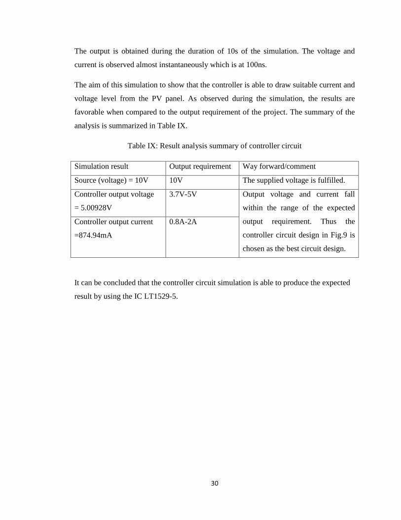
4.2. Prototype
Upon parameters determination in the methodology, a battery charger circuit is
designed and simulated in LT Spice V simulation software. The simulated circuit design
based on Fig.12 is able to produce a satisfactory result when compared to project output
requirement. Thus, the prototype of the project will be constructed based on the
parameters and components used during the simulation. Fig.16 below shows the picture
of the prototype.
Fig. 16: Project prototype
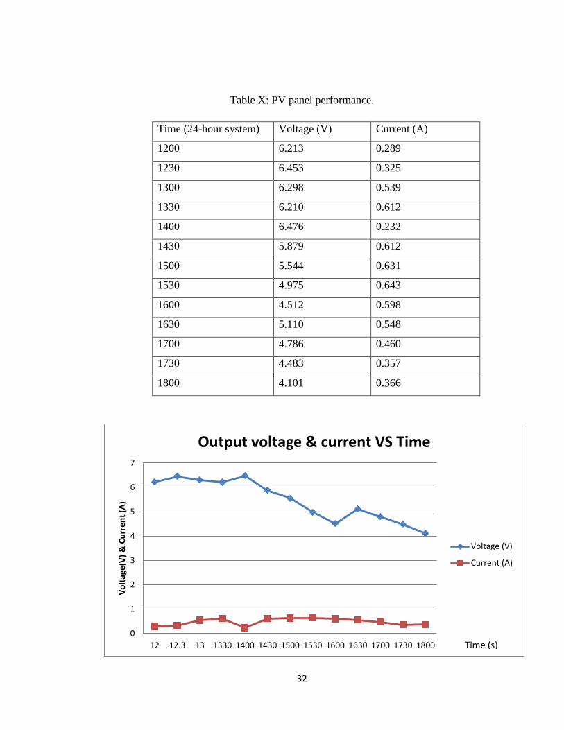
Upon a complete construction, the prototype is tested and result is observed and
tabulated for analysis. The result of the prototype is divided into two parts which are
the performance of the PV panel and the output voltage and current at the controller
output. Table IX show the performance of solar PV panel when tested during normal
sunny day. The output voltage and current are measured and is represented in Fig.
17.
32
Table X: PV panel performance.
Time (24-hour system) Voltage (V) Current (A)
1200 6.213 0.289
1230 6.453 0.325
1300 6.298 0.539
1330 6.210 0.612
1400 6.476 0.232
1430 5.879 0.612
1500 5.544 0.631
1530 4.975 0.643
1600 4.512 0.598
1630 5.110 0.548
1700 4.786 0.460
1730 4.483 0.357
1800 4.101 0.366
0
1
2
3
4
5
6
7
12 12.3 13 1330 1400 1430 1500 1530 1600 1630 1700 1730 1800
Vo
ltag
e(V
) &
Cu
rre
nt
(A)
Output voltage & current VS Time
Voltage (V)
Current (A)
Time (s)
33
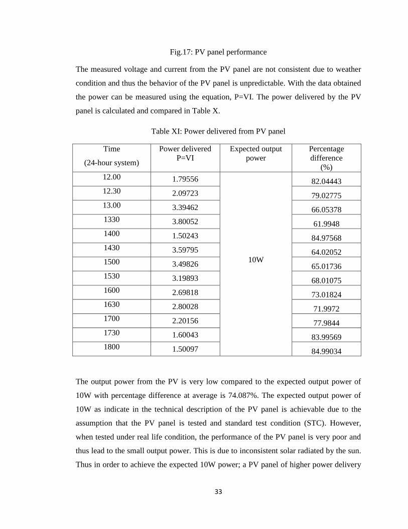
Fig.17: PV panel performance
The measured voltage and current from the PV panel are not consistent due to weather
condition and thus the behavior of the PV panel is unpredictable. With the data obtained
the power can be measured using the equation, P=VI. The power delivered by the PV
panel is calculated and compared in Table X.
Table XI: Power delivered from PV panel
Time
(24-hour system)
Power delivered
P=VI
Expected output
power
Percentage
difference
(%)
12.00 1.79556
10W
82.04443
12.30 2.09723 79.02775
13.00 3.39462 66.05378
1330 3.80052 61.9948
1400 1.50243 84.97568
1430 3.59795 64.02052
1500 3.49826 65.01736
1530 3.19893 68.01075
1600 2.69818 73.01824
1630 2.80028 71.9972
1700 2.20156 77.9844
1730 1.60043 83.99569
1800 1.50097 84.99034
The output power from the PV is very low compared to the expected output power of
10W with percentage difference at average is 74.087%. The expected output power of
10W as indicate in the technical description of the PV panel is achievable due to the
assumption that the PV panel is tested and standard test condition (STC). However,
when tested under real life condition, the performance of the PV panel is very poor and
thus lead to the small output power. This is due to inconsistent solar radiated by the sun.
Thus in order to achieve the expected 10W power; a PV panel of higher power delivery
34
should be used. However, due to size consideration and the feasibility of project in term
of cost, the PV panel of higher power rating is not possible.
The power fed to controller is very low and thus it is not enough for the controller to
produce the expected voltage and current level of 1V-5V and 1-2A respectively.
Measurements observed at the output of the controller are summarized in Table XII
below.
Table XII: Output voltage and current at controller output
Time (hour) Voltage (V) Current (A)
1200 4.03845 0.1734
1230 4.19445 0.195
1300 4.0937 0.3234
1330 4.0365 0.3672
1400 4.2094 0.1392
1430 3.82135 0.3672
1500 3.6036 0.3786
1530 3.23375 0.3858
1600 3.9328 0.3588
1630 3.3215 0.3288
1700 3.1109 0.276
1730 2.91395 0.2142
1800 2.6656 0.2196
The tabulated data on the Table XII is the average data summarized from multiple data
collection. Fig. 18 shows the graphical representation of data in Table XII.
35
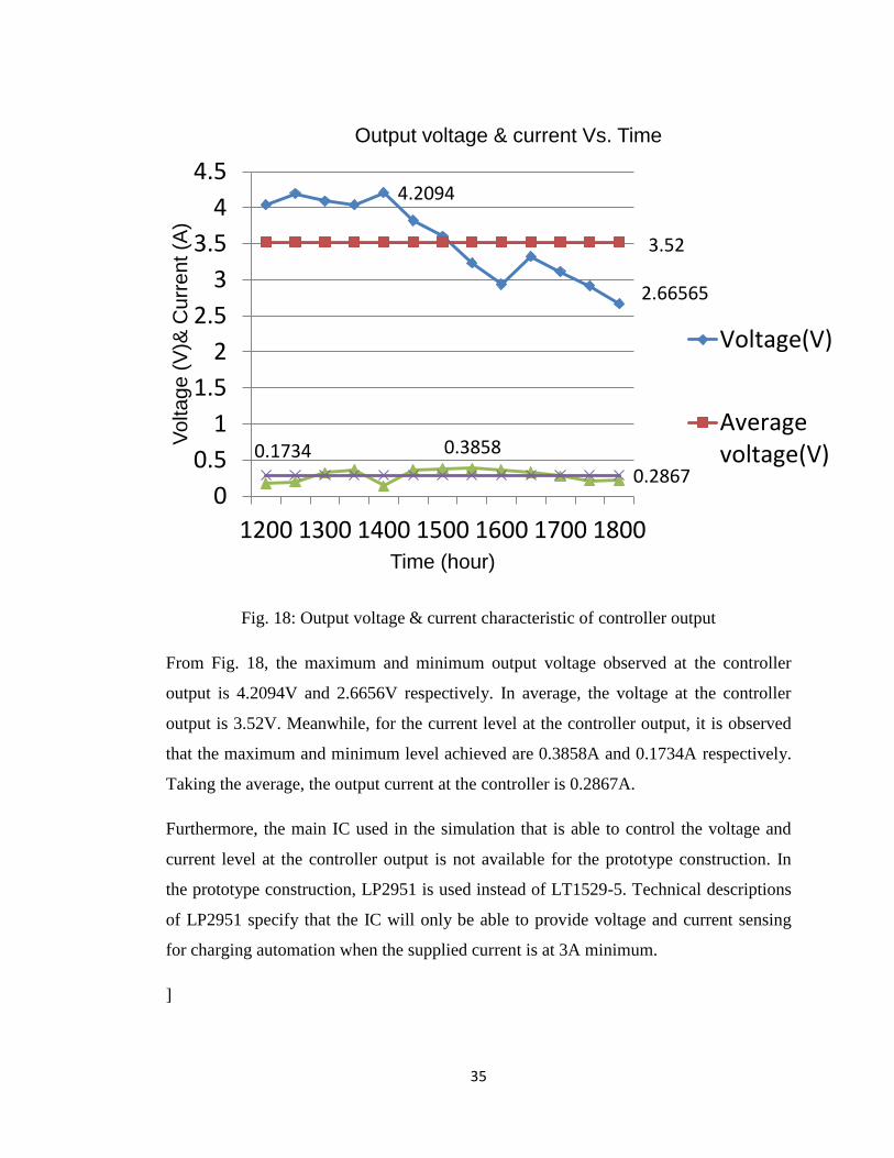
Fig. 18: Output voltage & current characteristic of controller output
From Fig. 18, the maximum and minimum output voltage observed at the controller
output is 4.2094V and 2.6656V respectively. In average, the voltage at the controller
output is 3.52V. Meanwhile, for the current level at the controller output, it is observed
that the maximum and minimum level achieved are 0.3858A and 0.1734A respectively.
Taking the average, the output current at the controller is 0.2867A.
Furthermore, the main IC used in the simulation that is able to control the voltage and
current level at the controller output is not available for the prototype construction. In
the prototype construction, LP2951 is used instead of LT1529-5. Technical descriptions
of LP2951 specify that the IC will only be able to provide voltage and current sensing
for charging automation when the supplied current is at 3A minimum.
]
4.2094
2.66565
3.52
0.1734 0.3858
0.2867 0
0.5
1
1.5
2
2.5
3
3.5
4
4.5
1200 1300 1400 1500 1600 1700 1800
Vo
lta
ge
(V
)& C
urr
en
t (A
)
Time (hour)
Output voltage & current Vs. Time
Voltage(V)
Averagevoltage(V)
36
CHAPTER 4: CONCLUSION & RECOMMENDATION
The approach of explore the possibility of embedding the application of solar PV
in generating a small scale circuitry power generation into a battery charger of mobile
applications is very good counter to the problem of limited battery lifetime that is issued
by users. In this project, A PV panel is used as a power supply to the battery charger
circuit. In the battery charger circuit, a controller is used to regulate the voltage and
current level for charging purposes. In the simulation, it is found that the output power
from the PV panel is maximum at 7.90854W with maximum current and voltage at 1A
and -1A at both positive and negative cycle and 10V respectively. After the prototype is
tested, it is observed that the output power of the PV panel is very low at 2.5913W in
average compare to the expected power requirement of 10W. Due to this low power
output, the controller circuit is unable to regulate the voltage and current to meet the
minimum requirement of voltage and current for charging which is 3.7V and 1A. Thus
no charging process is observed.
For future works, it is recommended that the selection of PV module of higher
performance and high efficiency when tested under real weather condition is required
and necessary to achieve the main objective of the project. It is also recommended that
the PV system that is introduced in the project is included with battery storage. This is to
ensure that the power supplied to the controller is constant and the controller is able
regulate voltage and current level accordingly.
37
REFERENCES
[1] A. De Luca, "Battery Charger," Definition of Battery Charger, vol. 3, pp. 50-70, 2009.
[2] D. Mohankumar, "Automatic Battery Charger," Power Supply, vol. 101, pp. 431-451, 2010.
[3] L. Pengfei, R. Bashirullah, and J. C. Principe, "A low power battery management system for rechargeable wireless implantable electronics," in Circuits and Systems, 2006. ISCAS 2006. Proceedings. 2006 IEEE International Symposium on, 2006, p. 4 pp.
[4] F. Vannieuwenborg, L. Mainil, S. Verbrugge, M. Pickavet, and D. Colle, "Business models for the mobile application market from a developer's viewpoint," in Intelligence in Next Generation Networks (ICIN), 2012 16th International Conference on, 2012, pp. 171-178.
[5] B. Kirubakaran and V. Karthikeyani, "Mobile application testing — Challenges and solution approach through automation," in Pattern Recognition, Informatics and Mobile Engineering (PRIME), 2013 International Conference on, 2013, pp. 79-84.
[6] J. Ramirez-Angulo, R. G. Carvajal, and A. Lopez-Martin, "Techniques for the Design of Low Voltage Power Efficient Analog and Mixed Signal Circuits," in VLSI Design, 2009 22nd International Conference on, 2009, pp. 26-27.
[7] W. Kun, Z. Wuxiong, and Y. Yang, "Prolonging battery usage time in smart phones," in Communications (ICC), 2013 IEEE International Conference on, 2013, pp. 2360-2364.
[8] S. Karimi, "How Battery Charger Works and The Different Types Available," Philosophy of Battery Charger vol. 7, pp. 234-279, 2009.
[9] H. Miwa, P. Sung-Yeul, B. T. Clark, D. Ditzler, G. Malone, N. S. D'Souza, et al., "Low cost universal battery charger for wide range input voltage and wide range output voltage in portable applications," in Power Electronics Specialists Conference, 2008. PESC 2008. IEEE, 2008, pp. 4699-4704.
[10] B. Lawson, "Battery Chargers and Charging Methods," Various Charging Methods, vol. 12, pp. 192-256, 2007.
[11] B. Do Valle, C. T. Wentz, and R. Sarpeshkar, "An Area and Power-Efficient Analog Li-Ion Battery Charger Circuit," Biomedical Circuits and Systems, IEEE Transactions on, vol. 5, pp. 131-137, 2011.
38
[12] L. Technology. (2014 Webopage, 14 July). LT1529 - 3A Low Dropout Regulators with Micropower Quiescent Current and Shutdown. Available: http://www.linear.com/product/LT1529
[13] H. Daocheng, D. Gilham, F. Weiyi, K. Pengju, F. Dianbo, and F. C. Lee, "High power density high efficiency dc/dc converter," in Energy Conversion Congress and Exposition (ECCE), 2011 IEEE, 2011, pp. 1392-1399.
[14] Y. Yusof, S. H. Sayuti, M. Abdul Latif, and M. Z. C. Wanik, "Modeling and simulation of maximum power point tracker for photovoltaic system," in Power and Energy Conference, 2004. PECon 2004. Proceedings. National, 2004, pp. 88-93.
[15] L. X. Heza taha Mahmoud, "A combined Li-ion & lead-acid battery system for start-stop application: potential & realization," vol. 9, pp. 23-45, 2012.
[16] I. Y. W. Chung and Y. C. Liang, "A low-cost photovoltaic energy harvesting circuit for portable devices," in Power Electronics and Drive Systems (PEDS), 2011 IEEE Ninth International Conference on, 2011, pp. 334-339.
[17] L. Chengliu, J. Wenyan, T. Quan, and S. Mingui, "Solar cell phone charger performance in indoor environment," in Bioengineering Conference (NEBEC), 2011 IEEE 37th Annual Northeast, 2011, pp. 1-2.
[18] T. M. e. a. T.Ikegami, "Estimation of equivalent circuit parameters of PV module and its application to optimal operation of PV system," Solar Energy Materials & solar cells vol. 5, 2001.
[19] B. J. Ramos, C.y. Franco. , "Modeling and parameter calculation of photovoltaic fields in irregular weather conditions," vol. 17, pp. 37-48, 2012.
[20] P. A. Corporation, "Photovoltaic Modelling " vol. 12, pp. 23-41, May 2011 2011.
[21] W. E. C. a. R. B. C.E Parfitt, "An Adaptable Lithium-Ion Battery
Model," vol. 28, pp. 21-23, 2011.
Recommended