Fax 630-859-0971 • Aurora Bearing Company • Aurora, Illinois 60506 • www.aurorabearing.com
AURORA BEARING COMPANY...Manufacturer and worldwide supplier
of the highest quality rod ends,spherical bearings, and
journal bushingsanywhere!
General InformationIn 1971 a new company entered the rod end and spheri-
cal bearing marketplace. This new firm, Aurora BearingCompany, soon became a major force in the rod end industry.
A strict “Quality discipline” covering all phases of businessincluding basic product design, marketing efforts, engineering,customer concern, timely delivery, and all phases of manufac-turing has advanced Aurora Bearing Company to the leader-ship role in the industrial marketplace.
By the middle of the 1980’s this total quality reputationwas recognized by the aircraft airframe industry, and AuroraBearing Company was solicited by the most prestigious air-frame manufacturers to build products for them to their speci-fications. This prompted the decision to seriously enter theaircraft market, and by 1988 Aurora Bearing Company wassoliciting aircraft business on a controlled basis only, in orderto insure consistent customer satisfaction. These effortsresulted in a smooth and successful entry into the aircraftmarketplace.
Aurora Bearing Company now produces standard andspecial spherical bearings, rod ends and bushings, for aircraftmanufacturers, their subcontractors, and approved aerospace
distributors. These customers span the entire aerospaceindustry including; Ultra Light Aircraft, General AviationAircraft, small and large Commercial Jet Liners, MilitaryAircraft, Space related applications up to and including criticalareas of the International Space Station.
Incorporated into this catalog are the standard lines ofspherical bearings, rod ends and bushings manufactured byAurora Bearing Company. We also pride ourselves in workingclosely with aircraft and space designers and engineeringgroups relative to the most stringent requirements. A sampleof these are pictured on the back cover of this catalog.
Aurora Bearing Company’s quality system ABC-9000, hasbeen surveyed, approved, and is subject to stringent ongoingreviews by many of the most prestigious aerospace cus-tomers.
A very competent international sales force, working withour dedicated engineering staff, is now in place for marketingthese products worldwide, and is available and anxious toassist and provide practical and sound solutions to bearingapplication problems and challenges.
Military Approved Bearings.We have received approval of our AT3200 PTFE Liner System (See page 31) to SAE-AS81820 (formerly Mil-B-81820), our
spherical bearings to SAE-AS14101 through SAE-AS14104 (formerly MS14101 through MS14104), our rod ends to SAE-AS81935 (formerly Mil-B-81935), our PTFE lined bushings to SAE-AS81934 (formerly Mil-B-81934). Total traceabilities aremaintained through manufacturing up to and including shipping.
Aircraft Bearings and Rod Ends not requiring Military ApprovalThese bearings and rod ends are manufactured under the same quality and SPC systems as the Military approved bear-
ings. Aurora Bearing Company has not sought approval for bearings in this section. However, many of the bearings and rodends have been approved to individual customer specifications and or standards. Total traceabilities are maintained throughmanufacturing up to and including shipping.
General Purpose Rod Ends and Spherical BearingsProducts listed in this section are used by the General Aviation, Experimental, Ultra Light aircraft industries, and in non-criti-
cal applications by Commercial Aircraft manufacturers. These bearings and rod ends are manufactured employing strict qualityrequirements. Total traceabilities are maintained on all parts except those on pages 28, 29, 30, and 31.
Engineering InformationThis section includes general engineering information frequently used by aircraft designers. For additional or more specific
engineering needs, contact our engineering department.
SECTION ONE:
SECTION TWO:
SECTION THREE:
SECTION FOUR:
Part Number Designation Page No.SECTION ONE:SAE-AS81935 MILITARY APPROVED ROD ENDS
ASM-T/ASB-T Male Rod Ends..................................................................................................................... 2-3ASW-T/ASG-T Female Rod Ends................................................................................................................. 4-5
SAE-AS14101, SAE-AS14102,SAE-AS14103 & SAE-AS14104 MILITARY APPROVED SPHERICAL BEARINGS
ANC-TG/ANC-T Narrow Spherical Bearings....................................................................................................................... 6-7AWC-TG/AWC-T Wide Spherical Bearings......................................................................................................................... 8-9
SAE-AS81934 Sleeve Bearings - PTFE LINED
AJB-TFA/TFC Flanged Journal Bushings........................................................................................................................ 10-11AJB-TA/TC Plain Journal Bushings..................................................................................................................................12-13
SECTION TWO:METAL TO METAL AIRCRAFT ROD ENDS
ASM/ASB Male Rod Ends.................................................................................................................................................... 14ASW/ASG Female Rod Ends............................................................................................................................................... 15
METAL TO METAL AIRCRAFT SPHERICAL BEARINGS
NC-G/NC Narrow Spherical Bearings................................................................................................................................... 16WC-G/WC Wide Spherical Bearings.....................................................................................................................................17
HIGH MISALIGNMENT MALE ROD ENDS
HXAM-TM-500 Male Rod Ends.............................................................................................................................................18
HIGH MISALIGNMENT SPHERICAL BEARINGS
HAB-T-500 Spherical Bearings............................................................................................................................................. 19
SECTION THREE:GENERAL AVIATION ROD ENDS
GMM-M/GMB-M Male Rod Ends.......................................................................................................................................... 20GMW-M/GMG-M Female Rod Ends..................................................................................................................................... 21MM-M-500/MB-M-500 Male Rod Ends................................................................................................................................. 22MW-M-500/MG-M-500 Female Rod Ends............................................................................................................................ 23MM-TM-500/MB-TM-500 Male Rod Ends.............................................................................................................................24MW-TM-500/MG-TM-500 Female Rod Ends........................................................................................................................25MM-M-M-500 Metric Male Rod Ends.................................................................................................................................... 26MW-M-M-500/MG-M-M-500 Metric Female Rod Ends......................................................................................................... 27CM/CB Male Rod Ends.........................................................................................................................................................28CW/CG Female Rod Ends....................................................................................................................................................29
GENERAL AVIATION SPHERICAL BEARINGS
COM/COM-T Spherical Bearings.......................................................................................................................................... 30AIB/SIB/MIB/MIB-T Spherical Bearings................................................................................................................................ 31
SECTION FOUR:ENGINEERING INFORMATION
Installation of Spherical Bearings.....................................................................................................................................32-34PTFE Liner Information......................................................................................................................................................... 35Major Specification Approvals............................................................................................................................................... 36Conversion Tables - Inch/Metric............................................................................................................................................37
Contents
Fax 630-859-0971 • Aurora Bearing Company • Aurora, Illinois 60506 • www.aurorabearing.com
Fax 630-859-0971 • Aurora Bearing Company • Aurora, Illinois 60506 • www.aurorabearing.com
D+ .010
H+ .005
B+.0000- .0005
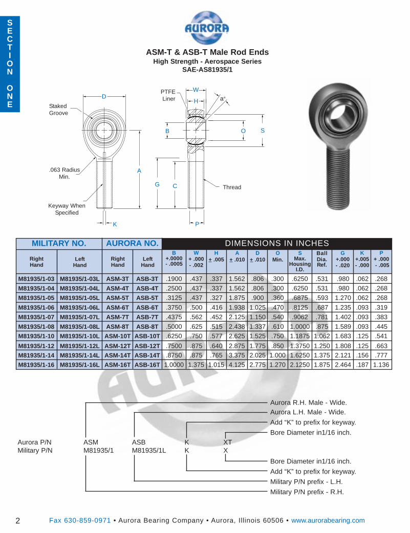
ASM-T & ASB-T Male Rod EndsHigh Strength - Aerospace Series
SAE-AS81935/1
D a°PTFELiner
W
G
B
H
O
.063 RadiusMin.
G+.000- .020
BallDia.Ref.
P+ .000- .005
DIMENSIONS IN INCHESW
+ .000- .002
RightHand
OMin.
SMax.
HousingI.D.
LeftHand
S
P
MILITARY NO.
2
M81935/1-03 M81935/1-03L ASM-3T ASB-3T .1900 .437 .337 1.562 .806 .300 .6250 .531 .980 .062 .268
M81935/1-04 M81935/1-04L ASM-4T ASB-4T .2500 .437 .337 1.562 .806 .300 .6250 .531 .980 .062 .268
M81935/1-05 M81935/1-05L ASM-5T ASB-5T .3125 .437 .327 1.875 .900 .360 .6875 .593 1.270 .062 .268
M81935/1-06 M81935/1-06L ASM-6T ASB-6T .3750 .500 .416 1.938 1.025 .470 .8125 .687 1.235 .093 .319
M81935/1-07 M81935/1-07L ASM-7T ASB-7T .4375 .562 .452 2.125 1.150 .540 .9062 .781 1.402 .093 .383
M81935/1-08 M81935/1-08L ASM-8T ASB-8T .5000 .625 .515 2.438 1.337 .610 1.0000 .875 1.589 .093 .445
M81935/1-10 M81935/1-10L ASM-10T ASB-10T .6250 .750 .577 2.625 1.525 .750 1.1875 1.062 1.683 .125 .541
M81935/1-12 M81935/1-12L ASM-12T ASB-12T .7500 .875 .640 2.875 1.775 .850 1.3750 1.250 1.808 .125 .663M81935/1-14 M81935/1-14L ASM-14T ASB-14T .8750 .875 .765 3.375 2.025 1.000 1.6250 1.375 2.121 .156 .777
M81935/1-16 M81935/1-16L ASM-16T ASB-16T 1.0000 1.375 1.015 4.125 2.775 1.270 2.1250 1.875 2.464 .187 1.136
K
A
C Thread
Keyway WhenSpecified
StakedGroove
K+.005- .000
A+ .010Right
HandLeft
Hand
AURORA NO.
Aurora R.H. Male - Wide.Aurora L.H. Male - Wide.
Add “K” to prefix for keyway.
Bore Diameter in1/16 inch.
Bore Diameter in1/16 inch.
Add “K” to prefix for keyway.
Military P/N prefix - L.H.
Military P/N prefix - R.H.
Aurora P/N ASM ASB K XTMilitary P/N M81935/1 M81935/1L K X
SECTION
ONE
Approx.Brg.Wt.Lbs.
Fax 630-859-0971 • Aurora Bearing Company • Aurora, Illinois 60506 • www.aurorabearing.com
ThreadUNJF-3A
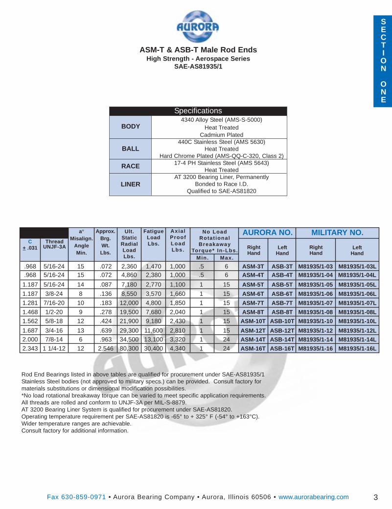
ASM-T & ASB-T Male Rod EndsHigh Strength - Aerospace Series
SAE-AS81935/1
a°Misalign.
AngleMin.
3
C+ .031
Specifications4340 Alloy Steel (AMS-S-5000)
Heat TreatedCadmium Plated
440C Stainless Steel (AMS 5630)Heat Treated
Hard Chrome Plated (AMS-QQ-C-320, Class 2)17-4 PH Stainless Steel (AMS 5643)
Heat TreatedAT 3200 Bearing Liner, Permanently
Bonded to Race I.D.Qualified to SAE-AS81820
BODY
BALL
RACE
LINER
Rod End Bearings listed in above tables are qualified for procurement under SAE-AS81935/1Stainless Steel bodies (not approved to military specs.) can be provided. Consult factory formaterials substitutions or dimensional modification possibilities.*No load rotational breakaway torque can be varied to meet specific application requirements.All threads are rolled and conform to UNJF-3A per MIL-S-8879.AT 3200 Bearing Liner System is qualified for procurement under SAE-AS81820.Operating temperature requirement per SAE-AS81820 is -65° to + 325° F (-54° to +163°C).Wider temperature ranges are achievable.Consult factory for additional information.
RightHand
LeftHand
.968 5/16-24 15 .072 2,360 1,470 1,000 .5 6 ASM-3T ASB-3T M81935/1-03 M81935/1-03L
.968 5/16-24 15 .072 4,860 2,380 1,000 .5 6 ASM-4T ASB-4T M81935/1-04 M81935/1-04L
1.187 5/16-24 14 .087 7,180 2,770 1,100 1 15 ASM-5T ASB-5T M81935/1-05 M81935/1-05L
1.187 3/8-24 8 .136 8,550 3,570 1,660 1 15 ASM-6T ASB-6T M81935/1-06 M81935/1-06L
1.281 7/16-20 10 .183 12,000 4,800 1,850 1 15 ASM-7T ASB-7T M81935/1-07 M81935/1-07L
1.468 1/2-20 9 .278 19,500 7,680 2,040 1 15 ASM-8T ASB-8T M81935/1-08 M81935/1-08L
1.562 5/8-18 12 .424 21,900 9,180 2,430 1 15 ASM-10T ASB-10T M81935/1-10 M81935/1-10L
1.687 3/4-16 13 .639 29,300 11,600 2,810 1 15 ASM-12T ASB-12T M81935/1-12 M81935/1-12L
2.000 7/8-14 6 .963 34,500 13,100 3,320 1 24 ASM-14T ASB-14T M81935/1-14 M81935/1-14L
2.343 1 1/4-12 12 2.546 80,300 30,400 4,340 1 24 ASM-16T ASB-16T M81935/1-16 M81935/1-16L
RightHand
LeftHand
Ult.StaticRadialLoadLbs.
FatigueLoadLbs.
Ax ia lProofLoadLbs.
Min. Max.
No LoadRotat ionalBreakaway
Torque* In-Lbs.
AURORA NO. MILITARY NO.
SECTION
ONE
SECTION
ONE
Fax 630-859-0971 • Aurora Bearing Company • Aurora, Illinois 60506 • www.aurorabearing.com
D+ .010
H+ .005
B+.0000- .0005
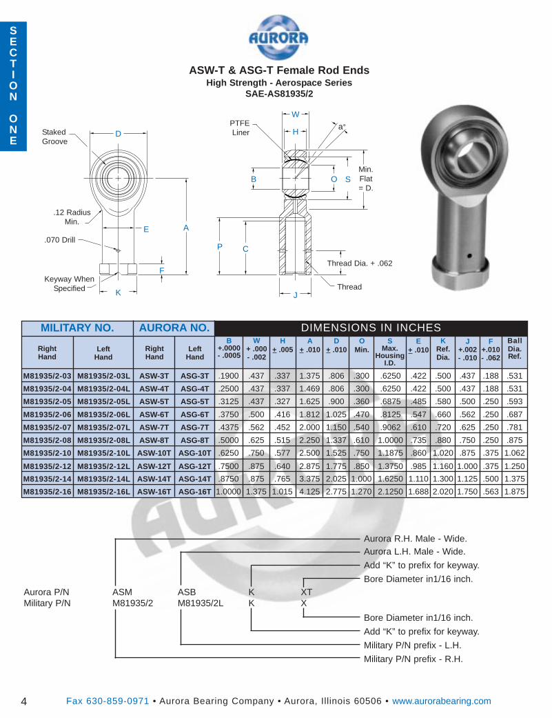
ASW-T & ASG-T Female Rod EndsHigh Strength - Aerospace Series
SAE-AS81935/2
BallDia.Ref.
DIMENSIONS IN INCHESW
+ .000- .002
RightHand
OMin.
SMax.
HousingI.D.
LeftHand
MILITARY NO.
4
M81935/2-03 M81935/2-03L ASW-3T ASG-3T .1900 .437 .337 1.375 .806 .300 .6250 .422 .500 .437 .188 .531
M81935/2-04 M81935/2-04L ASW-4T ASG-4T .2500 .437 .337 1.469 .806 .300 .6250 .422 .500 .437 .188 .531
M81935/2-05 M81935/2-05L ASW-5T ASG-5T .3125 .437 .327 1.625 .900 .360 .6875 .485 .580 .500 .250 .593
M81935/2-06 M81935/2-06L ASW-6T ASG-6T .3750 .500 .416 1.812 1.025 .470 .8125 .547 .660 .562 .250 .687
M81935/2-07 M81935/2-07L ASW-7T ASG-7T .4375 .562 .452 2.000 1.150 .540 .9062 .610 .720 .625 .250 .781
M81935/2-08 M81935/2-08L ASW-8T ASG-8T .5000 .625 .515 2.250 1.337 .610 1.0000 .735 .880 .750 .250 .875
M81935/2-10 M81935/2-10L ASW-10T ASG-10T .6250 .750 .577 2.500 1.525 .750 1.1875 .860 1.020 .875 .375 1.062
M81935/2-12 M81935/2-12L ASW-12T ASG-12T .7500 .875 .640 2.875 1.775 .850 1.3750 .985 1.160 1.000 .375 1.250
M81935/2-14 M81935/2-14L ASW-14T ASG-14T .8750 .875 .765 3.375 2.025 1.000 1.6250 1.110 1.300 1.125 .500 1.375
M81935/2-16 M81935/2-16L ASW-16T ASG-16T 1.0000 1.375 1.015 4.125 2.775 1.270 2.1250 1.688 2.020 1.750 .563 1.875
KRef.Dia.
A+ .010Right
HandLeft
Hand
AURORA NO.
Aurora R.H. Male - Wide.Aurora L.H. Male - Wide.
Add “K” to prefix for keyway.
Bore Diameter in1/16 inch.
Bore Diameter in1/16 inch.
Add “K” to prefix for keyway.
Military P/N prefix - L.H.
Military P/N prefix - R.H.
Aurora P/N ASM ASB K XTMilitary P/N M81935/2 M81935/2L K X
Da°PTFE
Liner
W
E
B
H
O
.12 RadiusMin.
J+.002- .010
S
P
K
A
C
ThreadKeyway When
Specified
StakedGroove
F+.010- .062
E+ .010
J
F
.070 Drill
Thread Dia. + .062
Min.Flat= D.
Approx.Brg.Wt.Lbs.
Fax 630-859-0971 • Aurora Bearing Company • Aurora, Illinois 60506 • www.aurorabearing.com
ThreadUNJF-3B
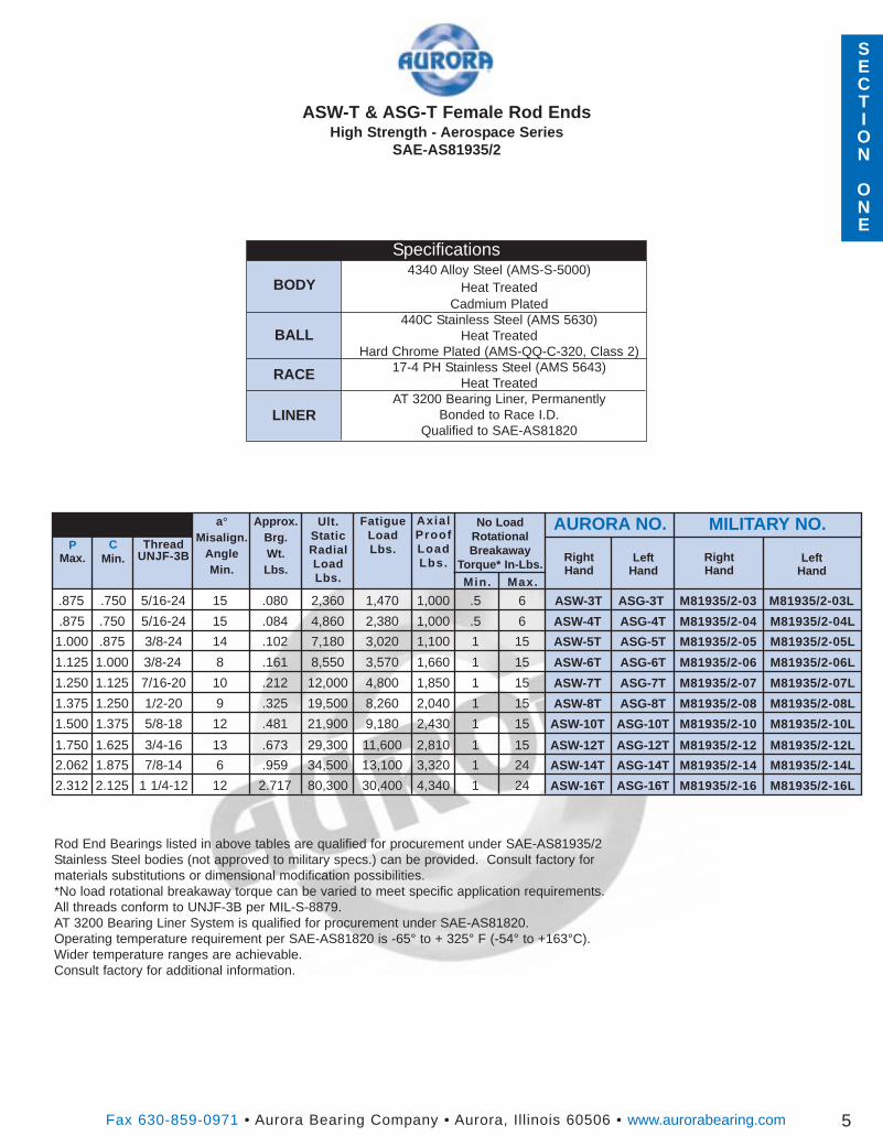
ASW-T & ASG-T Female Rod EndsHigh Strength - Aerospace Series
SAE-AS81935/2
a°Misalign.
AngleMin.
5
CMin.
Specifications4340 Alloy Steel (AMS-S-5000)
Heat TreatedCadmium Plated
440C Stainless Steel (AMS 5630)Heat Treated
Hard Chrome Plated (AMS-QQ-C-320, Class 2)17-4 PH Stainless Steel (AMS 5643)
Heat TreatedAT 3200 Bearing Liner, Permanently
Bonded to Race I.D.Qualified to SAE-AS81820
BODY
BALL
RACE
LINER
Rod End Bearings listed in above tables are qualified for procurement under SAE-AS81935/2Stainless Steel bodies (not approved to military specs.) can be provided. Consult factory formaterials substitutions or dimensional modification possibilities.*No load rotational breakaway torque can be varied to meet specific application requirements.All threads conform to UNJF-3B per MIL-S-8879.AT 3200 Bearing Liner System is qualified for procurement under SAE-AS81820.Operating temperature requirement per SAE-AS81820 is -65° to + 325° F (-54° to +163°C).Wider temperature ranges are achievable.Consult factory for additional information.
RightHand
LeftHand
.875 .750 5/16-24 15 .080 2,360 1,470 1,000 .5 6 ASW-3T ASG-3T M81935/2-03 M81935/2-03L
.875 .750 5/16-24 15 .084 4,860 2,380 1,000 .5 6 ASW-4T ASG-4T M81935/2-04 M81935/2-04L
1.000 .875 3/8-24 14 .102 7,180 3,020 1,100 1 15 ASW-5T ASG-5T M81935/2-05 M81935/2-05L
1.125 1.000 3/8-24 8 .161 8,550 3,570 1,660 1 15 ASW-6T ASG-6T M81935/2-06 M81935/2-06L
1.250 1.125 7/16-20 10 .212 12,000 4,800 1,850 1 15 ASW-7T ASG-7T M81935/2-07 M81935/2-07L
1.375 1.250 1/2-20 9 .325 19,500 8,260 2,040 1 15 ASW-8T ASG-8T M81935/2-08 M81935/2-08L
1.500 1.375 5/8-18 12 .481 21,900 9,180 2,430 1 15 ASW-10T ASG-10T M81935/2-10 M81935/2-10L
1.750 1.625 3/4-16 13 .673 29,300 11,600 2,810 1 15 ASW-12T ASG-12T M81935/2-12 M81935/2-12L
2.062 1.875 7/8-14 6 .959 34,500 13,100 3,320 1 24 ASW-14T ASG-14T M81935/2-14 M81935/2-14L
2.312 2.125 1 1/4-12 12 2.717 80,300 30,400 4,340 1 24 ASW-16T ASG-16T M81935/2-16 M81935/2-16L
RightHand
LeftHand
Ult.StaticRadialLoadLbs.
FatigueLoadLbs.
Ax ia lProofLoadLbs.
Min. Max.
No LoadRotationalBreakaway
Torque* In-Lbs.
AURORA NO. MILITARY NO.P
Max.
SECTION
ONE
Fax 630-859-0971 • Aurora Bearing Company • Aurora, Illinois 60506 • www.aurorabearing.com
OMin.
W+ .000- .002
B+ .0000- .0005
R‡+ .002- .005
G+ .000- .008
a°
DIMENSIONS IN INCHESD
+ .0000- .0005
GROOVED **
P+ .000- .010
SMin.PLAIN
MILITARY NO.
6
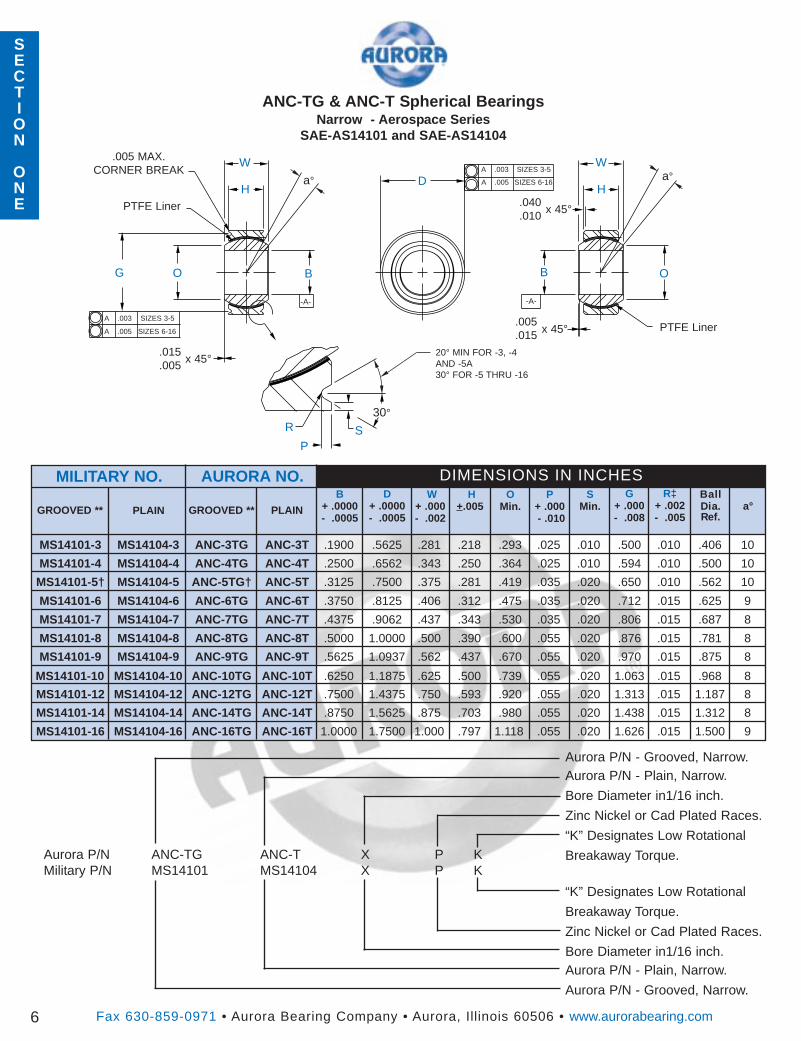
MS14101-3 MS14104-3 ANC-3TG ANC-3T .1900 .5625 .281 .218 .293 .025 .010 .500 .010 .406 10
MS14101-4 MS14104-4 ANC-4TG ANC-4T .2500 .6562 .343 .250 .364 .025 .010 .594 .010 .500 10
MS14101-5† MS14104-5 ANC-5TG† ANC-5T .3125 .7500 .375 .281 .419 .035 .020 .650 .010 .562 10
MS14101-6 MS14104-6 ANC-6TG ANC-6T .3750 .8125 .406 .312 .475 .035 .020 .712 .015 .625 9
MS14101-7 MS14104-7 ANC-7TG ANC-7T .4375 .9062 .437 .343 .530 .035 .020 .806 .015 .687 8
MS14101-8 MS14104-8 ANC-8TG ANC-8T .5000 1.0000 .500 .390 .600 .055 .020 .876 .015 .781 8
MS14101-9 MS14104-9 ANC-9TG ANC-9T .5625 1.0937 .562 .437 .670 .055 .020 .970 .015 .875 8
MS14101-10 MS14104-10 ANC-10TG ANC-10T .6250 1.1875 .625 .500 .739 .055 .020 1.063 .015 .968 8
MS14101-12 MS14104-12 ANC-12TG ANC-12T .7500 1.4375 .750 .593 .920 .055 .020 1.313 .015 1.187 8
MS14101-14 MS14104-14 ANC-14TG ANC-14T .8750 1.5625 .875 .703 .980 .055 .020 1.438 .015 1.312 8
MS14101-16 MS14104-16 ANC-16TG ANC-16T 1.0000 1.7500 1.000 .797 1.118 .055 .020 1.626 .015 1.500 9
BallDia.Ref.
H+.005GROOVED ** PLAIN
AURORA NO.
Aurora P/N - Grooved, Narrow.Aurora P/N - Plain, Narrow.
Bore Diameter in1/16 inch.
Zinc Nickel or Cad Plated Races.
“K” Designates Low Rotational
Breakaway Torque.
“K” Designates Low Rotational
Breakaway Torque.
Zinc Nickel or Cad Plated Races.
Bore Diameter in1/16 inch.Aurora P/N - Plain, Narrow.
Aurora P/N - Grooved, Narrow.
Aurora P/N ANC-TG ANC-T X P KMilitary P/N MS14101 MS14104 X P K
ANC-TG & ANC-T Spherical BearingsNarrow - Aerospace Series
SAE-AS14101 and SAE-AS14104
D a°
PTFE Liner
W
G B
H
O
.005
.015
SP
B O
W
Ha°
x 45°
.015
.005x 45°
30°
.005 MAX.CORNER BREAK
R
PTFE Liner .040.010
x 45°
A .003 SIZES 3-5
A .005 SIZES 6-16
A .003 SIZES 3-5
A .005 SIZES 6-16
-A- -A-
20° MIN FOR -3, -4AND -5A30° FOR -5 THRU -16
SECTION
ONE
SECTION
ONE

Fax 630-859-0971 • Aurora Bearing Company • Aurora, Illinois 60506 • www.aurorabearing.com
ANC-TG & ANC-T Spherical BearingsNarrow - Aerospace Series
SAE-AS14101 and SAE-AS14104
7
PLAINSERIES
GROOVEDSERIES
BALL
RACE
LINER
Bearings listed in above tables are qualified for procurement under SAE-AS14101 and SAE-AS14104.“K” Type Low Torque Bearing fit requirements are listed above. Other variations of torque requirements can bevaried to meet specific application requirements.AT 3200 Bearing Liner System is qualified for procurement under SAE-AS81820.Operating temperature requirement per SAE-AS81820 is -65° to + 325° F (-54° to +163°C).Wider temperature ranges are achievable.*Standard fit bearings are void of any “radial” or “axial” clearance.**For further staking groove and assembly information, see pages 33 and 34Consult factory for additional information.†-5A is identical to -5 except “G” dimension is .660‡+.000, -.005 for -3, -4, -5A.
Specifications440C Stainless Steel (AMS 5630)
Heat TreatedHard Chrome Plated
17-4 PH Stainless Steel (AMS 5643)Heat Treated
AT 3200 Bearing Liner, PermanentlyBonded to Race I.D.
Qualified to SAE-AS81820
GROOVED ** PLAIN
3,975 150 1,500 0.25 - 5.0 0.5 .0007 .0028 .020 ANC-3TG ANC-3T MS14101-3 MS14104-3
6,040 430 3,320 0.25 - 5.0 0.5 .0007 .0028 .020 ANC-4TG ANC-4T MS14101-4 MS14104-4
8,750 700 5,460 0.25 - 8.0 1.0 .0007 .0028 .030 ANC-5TG† ANC-5T MS14101-5† MS14104-5
10,540 1,100 6,600 0.25 - 8.0 1.0 .0007 .0028 .040 ANC-6TG ANC-6T MS14101-6 MS14104-6
13,200 1,400 8,050 0.25 - 8.0 1.0 .0007 .0028 .050 ANC-7TG ANC-7T MS14101-7 MS14104-7
17,900 2,100 10,400 0.25 - 8.0 1.0 .0007 .0028 .070 ANC-8TG ANC-8T MS14101-8 MS14104-8
23,200 3,680 13,000 0.25 - 8.0 1.0 .0007 .0028 .090 ANC-9TG ANC-9T MS14101-9 MS14104-9
30,500 4,720 16,450 0.25 - 8.0 1.0 .0007 .0028 .120 ANC-10TG ANC-10T MS14101-10 MS14104-10
46,400 6,750 23,600 0.25 - 8.0 1.0 .0007 .0028 .210 ANC-12TG ANC-12T MS14101-12 MS14104-12
62,200 9,350 30,250 0.25 - 12.0 2.0 .0010 .0040 .270 ANC-14TG ANC-14T MS14101-14 MS14104-14
82,200 12,160 38,000 0.25 - 12.0 2.0 .0010 .0040 .390 ANC-16TG ANC-16T MS14101-16 MS14104-16
GROOVED ** PLAINRadialLbs.
Ax ia lClearance
Max.
No LoadRotat ionalBreakaway
Torque Max.In-Lbs.
AURORA NO. MILITARY NO.
Radia lClearance
Max.
Standard Fi tNo Load
Rotat ionalBreakaway
Torque Max.In-Lbs.
AxialLbs.
Approx.Brg.Wt.Lbs.
Oscil-latingLoadLbs.
“K” Fit
Bearing Fits
SECTION
ONE

SECTION
ONE
Fax 630-859-0971 • Aurora Bearing Company • Aurora, Illinois 60506 • www.aurorabearing.com
OMin.
W+ .000- .002
B+ .0000- .0005
R+.002- .005
G+.000- .008
a°
DIMENSIONS IN INCHESD
+ .0000- .0005
GROOVED **P
+ .000- .010
SMin.PLAIN
MILITARY NO.
8
MS14103-3 MS14102-3 AWC-3TG AWC-3T .1900 .6250 .437 .327 .300 .025 .010 .563 .010 .531 15
MS14103-4 MS14102-4 AWC-4TG AWC-4T .2500 .6250 .437 .327 .300 .025 .010 .563 .010 .531 15
MS14103-5 MS14102-5 AWC-5TG AWC-5T .3125 .6875 .437 .317 .360 .025 .010 .625 .010 .593 14
MS14103-6 MS14102-6 AWC-6TG AWC-6T .3750 .8125 .500 .406 .466 .035 .020 .712 .015 .687 8
MS14103-7† MS14102-7 AWC-7TG† AWC-7T .4375 .9375 .562 .442 .537 .035 .020 .837 .015 .781 10
MS14103-8 MS14102-8 AWC-8TG AWC-8T .5000 1.0000 .625 .505 .607 .035 .020 .900 .015 .875 9
MS14103-9 MS14102-9 AWC-9TG AWC-9T .5625 1.1250 .687 .536 .721 .035 .020 1.025 .015 1.000 10
MS14103-10 MS14102-10 AWC-10TG AWC-10T .6250 1.1875 .750 .567 .747 .035 .020 1.087 .015 1.062 12
MS14103-12 MS14102-12 AWC-12TG AWC-12T .7500 1.3750 .875 .630 .845 .055 .020 1.251 .015 1.250 13
MS14103-14 MS14102-14 AWC-14TG AWC-14T .8750 1.6250 .875 .755 .995 .055 .020 1.501 .015 1.375 6
MS14103-16 MS14102-16 AWC-16TG AWC-16T 1.0000 2.1250 1.375 1.005 1.269 .055 .020 2.001 .015 1.875 12
BallDia.Ref.
H+ .005GROOVED ** PLAIN
AURORA NO.
Aurora P/N - Grooved, Wide.Aurora P/N - Plain, Wide.
Bore Diameter in1/16 inch.
Zinc Nickel or Cad Plated Races.
“K” Designates Low Rotational
Breakaway Torque.
“K” Designates Low Rotational
Breakaway Torque.
Zinc Nickel or Cad Plated Races.
Bore Diameter in1/16 inch.Aurora P/N - Plain, Wide.
Aurora P/N - Grooved, Wide.
Aurora P/N AWC-TG AWC-T X P KMilitary P/N MS14103 MS14102 X P K
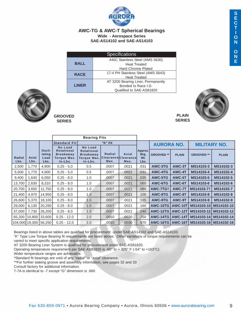
AWC-TG & AWC-T Spherical BearingsWide - Aerospace Series
SAE-AS14102 and SAE-AS14103
D a°
PTFE Liner
W
G B
H
O
.005
.015
SP
B O
W
Ha°
x 45°
.015
.005x 45°
30°
.005 MAX.CORNER BREAK
R
PTFE Liner .040.010
x 45°
A .003 SIZES 3-5
A .005 SIZES 6-16
A .003 SIZES 3-5
A .005 SIZES 6-16
-A- -A-
20° MIN FOR -3, -4AND -5A30° FOR -5 THRU -16
SECTION
ONE
Fax 630-859-0971 • Aurora Bearing Company • Aurora, Illinois 60506 • www.aurorabearing.com
AWC-TG & AWC-T Spherical BearingsWide - Aerospace Series
SAE-AS14102 and SAE-AS14103
9
PLAINSERIES
GROOVEDSERIES
BALL
RACE
LINER
Bearings listed in above tables are qualified for procurement under SAE-AS14102 and SAE-AS14103.“K” Type Low Torque Bearing fit requirements are listed above. Other variations of torque requirements can bevaried to meet specific application requirements.AT 3200 Bearing Liner System is qualified for procurement under SAE-AS81820.Operating temperature requirement per SAE-AS81820 is -65° to + 325° F (-54° to +163°C).Wider temperature ranges are achievable.*Standard fit bearings are void of any “radial” or “axial” clearance.**For further staking groove and assembly information, see pages 32 and 33Consult factory for additional information.†-7A is identical to -7 except “G” dimension is .660
Specifications440C Stainless Steel (AMS 5630)
Heat TreatedHard Chrome Plated
17-4 PH Stainless Steel (AMS 5643)Heat Treated
AT 3200 Bearing Liner, PermanentlyBonded to Race I.D.
Qualified to SAE-AS81820
GROOVED ** PLAIN
2,500 1,770 4,900 0.25 - 5.0 0.5 .0007 .0021 .031 AWC-3TG AWC-3T MS14103-3 MS14102-3
5,500 1,770 4,900 0.25 - 5.0 0.5 .0007 .0021 .031 AWC-4TG AWC-4T MS14103-4 MS14102-4
9,400 1,640 6,050 0.25 - 8.0 1.0 .0007 .0021 .035 AWC-5TG AWC-5T MS14103-5 MS14102-5
13,700 2,630 8,310 0.25 - 8.0 1.0 .0007 .0021 .060 AWC-6TG AWC-6T MS14103-6 MS14102-6
20,700 3,650 11,750 0.25 - 8.0 1.0 .0007 .0021 .080 AWC-7TG† AWC-7T MS14103-7† MS14102-7
21,400 4,970 14,950 0.25 - 8.0 1.0 .0007 .0021 .100 AWC-8TG AWC-8T MS14103-8 MS14102-8
26,600 5,370 18,100 0.25 - 8.0 1.0 .0007 .0021 .135 AWC-9TG AWC-9T MS14103-9 MS14102-9
29,000 6,130 20,250 0.25 - 8.0 1.0 .0007 .0021 .160 AWC-10TG AWC-10T MS14103-10 MS14102-10
37,000 7,730 26,200 0.25 - 8.0 1.0 .0007 .0021 .240 AWC-12TG AWC-12T MS14103-12 MS14102-12
65,200 10,800 33,600 0.25 - 12.0 2.0 .0010 .0030 .350 AWC-14TG AWC-14T MS14103-14 MS14102-14
104,000 19,300 56,250 0.25 - 12.0 2.0 .0010 .0030 .970 AWC-16TG AWC-16T MS14103-16 MS14102-16
GROOVED ** PLAINRadialLbs.
Ax ia lClearance
Max.
No LoadRotat ionalBreakaway
Torque Max.In-Lbs.
AURORA NO. MILITARY NO.
Radia lClearance
Max.
Standard Fi tNo Load
Rotat ionalBreakaway
Torque Max.In-Lbs.
AxialLbs.
Approx.Brg.Wt.Lbs.
Oscil-latingLoadLbs.
“K” Fit
Bearing Fits
SECTION
ONE
CRESAlum.
Fax 630-859-0971 • Aurora Bearing Company • Aurora, Illinois 60506 • www.aurorabearing.com
D+.0000- .0005
H+ .000- .020
B+.0000- .0010
Weight*Lbs./Inch (Ref)
L-1.00
DIMENSIONS IN INCHESW
+ .000- .005
BUSHING NO.
10
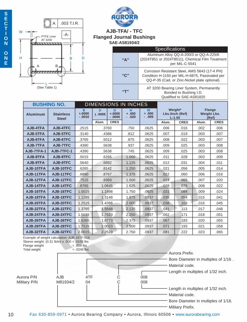
AJB-4TFA AJB-4TFC .2515 .3760 .750 .0625 .006 .016 .002 .006
AJB-5TFA AJB-5TFC .3140 .4386 .812 .0625 .007 .019 .003 .007
AJB-6TFA AJB-6TFC .3765 .5012 .875 .0625 .008 .022 .003 .007
AJB-7TFA AJB-7TFC .4390 .5638 .937 .0625 .009 .025 .003 .008
AJB-7TFA-1 AJB-7TFC-1 .4390 .5638 .745 .0625 .009 .025 .003 .008
AJB-8TFA AJB-8TFC .5015 .6265 1.000 .0625 .011 .028 .003 .009
AJB-9TFA AJB-9TFC .5640 .6892 1.125 .0625 .012 .031 .004 .011
AJB-10TFA AJB-10TFC .6265 .8142 1.250 .0625 .021 .056 .005 .014
AJB-11TFA AJB-11TFC .6890 .8767 1.375 .0625 .022 .060 .006 .016
AJB-12TFA AJB-12TFC .7515 .9393 1.500 .0625 .024 .065 .007 .020
AJB-14TFA AJB-14TFC .8765 1.0645 1.625 .0625 .028 .075 .008 .022
AJB-16TFA AJB-16TFC 1.0015 1.1898 1.750 .0625 .031 .084 .009 .024
AJB-18TFA AJB-18TFC 1.1265 1.3148 1.875 .0937 .035 .094 .015 .041
AJB-20TFA AJB-20TFC 1.2515 1.4398 2.000 .0937 .038 .103 .016 .045
AJB-22TFA AJB-22TFC 1.3765 1.5648 2.125 .0937 .041 .113 .017 .048
AJB-24TFA AJB-24TFC 1.5015 1.7523 2.250 .0937 .062 .171 .018 .051
AJB-26TFA AJB-26TFC 1.6265 1.8773 2.375 .0937 .067 .183 .020 .055
AJB-28TFA AJB-28TFC 1.7515 2.0023 2.500 .0937 .071 .193 .021 .058
AJB-32TFA AJB-32TFC 2.0015 2.2523 2.750 .0937 .081 .222 .023 .065
D+ .0005Aluminum Stainless
SteelCRESAlum. Alum. CRES
FlangeWeight Lbs.
(Ref)
“A”
“C”
“T”
SpecificationsAluminum Alloy QQ-A-200/3 or QQ-A-225/6
(2024T851 or 2024T8511), Chemical Film Treatmentper MIL-C-5541
Corrosion Resistant Steel, AMS 5643 (17-4 PH)Condition H-1150 per MIL-H-6875, Passivated per
QQ-P-35 (Cad, or Zinc-Nickel plate optional).
AT 3200 Bearing Liner System, PermanentlyBonded to Bushing I.D.
Qualified to SAE-AS81820
Example of weight calculation: AJB-16TF-016Sleeve weight: (0.31 lb/in) x .500 = .0155 lbsFlange weight = .009 lbsTotal weight = .0245 lbs
Aurora Prefix.
Bore Diameter in multiples of 1/16 .
Material code.
Length in multiples of 1/32 inch.
Length in multiples of 1/32 inch.
Material code.
Bore Diameter in multiples of 1/16.
Military Prefix.
Aurora P/N AJB 4TF C 008Military P/N M81934/2 04 C 008
D
W
B
H B
L
A
A .003 T.I.R.
-A-AJB-TFA/ - TFC
Flanged Journal BushingsSAE-AS81934/2
PTFE LinerAT 3200
(See Table 1)
Fax 630-859-0971 • Aurora Bearing Company • Aurora, Illinois 60506 • www.aurorabearing.com
AJB-TFA/ - TFC Flanged Journal BushingsSAE-AS81934/2
11
DASHNO.
NOMINALSIZE
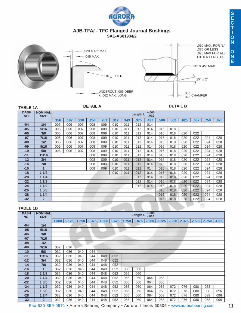
-04 1/4 005 006 007 008 009 010 011 012 014.156 .187 .218 .250 .281 .312 .343 .375 .437 .500 .562 .625 .687 .750 .875
-05 5/16 005 006 007 008 009 010 011 012 014 016 018-06 3/8 005 006 007 008 009 010 011 012 014 016 018 020 022-07 7/16 005 006 007 008 009 010 011 012 014 016 018 020 022 024 028-08 1/2 005 006 007 008 009 010 011 012 014 016 018 020 022 024 028-09 9/16 005 006 007 008 009 010 011 012 014 016 018 020 022 024 028-10 5/8 005 006 007 008 009 010 011 012 014 016 018 020 022 024 028-11 11/16 008 009 010 011 012 014 016 018 020 022 024 028-12 3/4 008 009 010 011 012 014 016 018 020 022 024 028-14 7/8 008 009 010 011 012 014 016 018 020 022 024 028-16 1 008 009 010 011 012 014 016 018 020 022 024 028-18 1 1/8 010 011 012 014 016 018 020 022 024 028-20 1 1/4 012 014 016 018 020 022 024 028-22 1 3/8 012 014 016 018 020 022 024 028-24 1 1/2 012 014 016 018 020 022 024 028-26 1 5/8 016 018 020 022 024 028-28 1 3/4 016 018 020 022 024 028-32 2 016 018 020 022 024 028
-04 1/41.000 1.125 1.250 1.375 1.500 1.625 1.750 1.875 2.000 2.125 2.250 2.375 2.500 2.750 3.000
-05 5/16-06 3/8-07 7/16-08 1/2-09 9/16 032 036-10 5/8 032 036 040 044-11 11/16 032 036 040 044 048 052-12 3/4 032 036 040 044 048 052-14 7/8 032 036 040 044 048 052-16 1 032 036 040 044 048 052 056 060-18 1 1/8 032 036 040 044 048 052 056 060-20 1 1/4 032 036 040 044 048 052 056 060 064 068-22 1 3/8 032 036 040 044 048 052 056 060 064 068-24 1 1/2 032 036 040 044 048 052 056 060 064 068 072 076 080 088-26 1 5/8 032 036 040 044 048 052 056 060 064 068 072 076 080 088 096-28 1 3/4 032 036 040 044 048 052 056 060 064 068 072 076 080 088 096-32 2 032 036 040 044 048 052 056 060 064 068 072 076 080 088 096
TABLE 1A
TABLE 1BDASHNO.
NOMINALSIZE
Length L +.000-.010
Length L +.000-.010
.015 X 45° MAX.
15° + 2°
CHAMFER
.010 MAX. FOR “L”
.375 OR LESS
.025 MAX FOR ALLOTHER LENGTHS.
.030
.020
SECTION
ONE
DETAIL A DETAIL B
SECTION
ONE
SECTION
ONE
.010 + .005 R
UNDERCUT .005 DEEPX .062 MAX. LONG
.020 X 45° MAX.
.045 MAX.
SECTION
ONE
CRESAlum.
Fax 630-859-0971 • Aurora Bearing Company • Aurora, Illinois 60506 • www.aurorabearing.com
D+.0000- .0005
B+.0000- .0010
Weight*Lbs./Inch (Ref)
L-1.00
DIMENSIONS IN INCHESBUSHING NO.
12
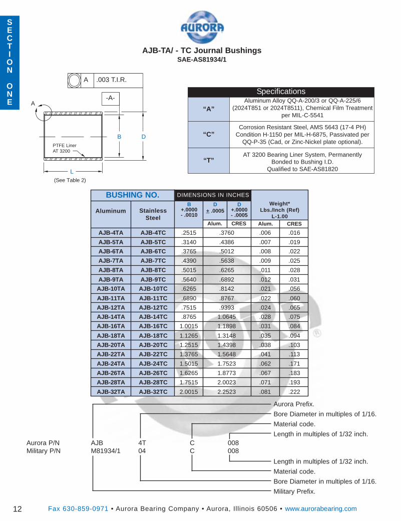
AJB-4TA AJB-4TC .2515 .3760 .006 .016
AJB-5TA AJB-5TC .3140 .4386 .007 .019
AJB-6TA AJB-6TC .3765 .5012 .008 .022
AJB-7TA AJB-7TC .4390 .5638 .009 .025
AJB-8TA AJB-8TC .5015 .6265 .011 .028
AJB-9TA AJB-9TC .5640 .6892 .012 .031
AJB-10TA AJB-10TC .6265 .8142 .021 .056
AJB-11TA AJB-11TC .6890 .8767 .022 .060
AJB-12TA AJB-12TC .7515 .9393 .024 .065
AJB-14TA AJB-14TC .8765 1.0645 .028 .075
AJB-16TA AJB-16TC 1.0015 1.1898 .031 .084
AJB-18TA AJB-18TC 1.1265 1.3148 .035 .094
AJB-20TA AJB-20TC 1.2515 1.4398 .038 .103
AJB-22TA AJB-22TC 1.3765 1.5648 .041 .113
AJB-24TA AJB-24TC 1.5015 1.7523 .062 .171
AJB-26TA AJB-26TC 1.6265 1.8773 .067 .183
AJB-28TA AJB-28TC 1.7515 2.0023 .071 .193
AJB-32TA AJB-32TC 2.0015 2.2523 .081 .222
D+ .0005Aluminum Stainless
SteelCRESAlum.
“A”
“C”
“T”
SpecificationsAluminum Alloy QQ-A-200/3 or QQ-A-225/6
(2024T851 or 2024T8511), Chemical Film Treatmentper MIL-C-5541
Corrosion Resistant Steel, AMS 5643 (17-4 PH)Condition H-1150 per MIL-H-6875, Passivated per
QQ-P-35 (Cad, or Zinc-Nickel plate optional).
AT 3200 Bearing Liner System, PermanentlyBonded to Bushing I.D.
Qualified to SAE-AS81820
Aurora Prefix.
Bore Diameter in multiples of 1/16.
Material code.
Length in multiples of 1/32 inch.
Length in multiples of 1/32 inch.
Material code.
Bore Diameter in multiples of 1/16.
Military Prefix.
Aurora P/N AJB 4T C 008Military P/N M81934/1 04 C 008
DB
L
A .003 T.I.R.
-A-
AJB-TA/ - TC Journal BushingsSAE-AS81934/1
PTFE LinerAT 3200
(See Table 2)
A
SECTION
ONE
SECTION
ONE
Fax 630-859-0971 • Aurora Bearing Company • Aurora, Illinois 60506 • www.aurorabearing.com
AJB-TA/ - TC Straight Journal BushingsSAE-AS81934/1
13
DASHNO.
NOMINALSIZE
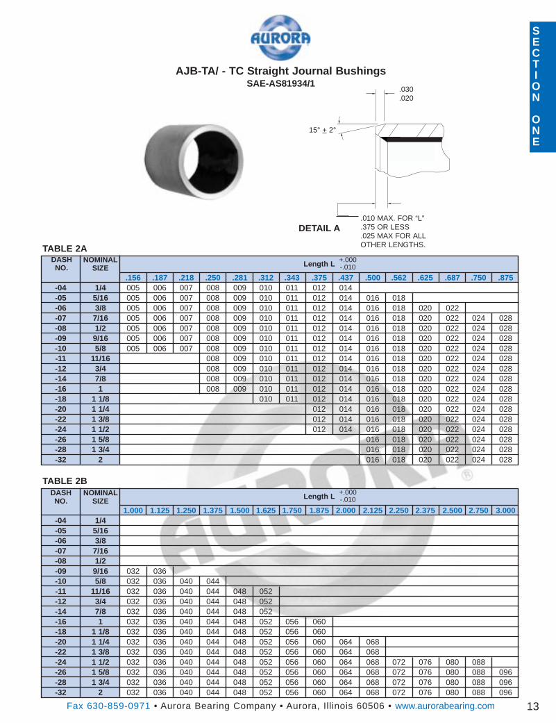
-04 1/4 005 006 007 008 009 010 011 012 014.156 .187 .218 .250 .281 .312 .343 .375 .437 .500 .562 .625 .687 .750 .875
-05 5/16 005 006 007 008 009 010 011 012 014 016 018-06 3/8 005 006 007 008 009 010 011 012 014 016 018 020 022-07 7/16 005 006 007 008 009 010 011 012 014 016 018 020 022 024 028-08 1/2 005 006 007 008 009 010 011 012 014 016 018 020 022 024 028-09 9/16 005 006 007 008 009 010 011 012 014 016 018 020 022 024 028-10 5/8 005 006 007 008 009 010 011 012 014 016 018 020 022 024 028-11 11/16 008 009 010 011 012 014 016 018 020 022 024 028-12 3/4 008 009 010 011 012 014 016 018 020 022 024 028-14 7/8 008 009 010 011 012 014 016 018 020 022 024 028-16 1 008 009 010 011 012 014 016 018 020 022 024 028-18 1 1/8 010 011 012 014 016 018 020 022 024 028-20 1 1/4 012 014 016 018 020 022 024 028-22 1 3/8 012 014 016 018 020 022 024 028-24 1 1/2 012 014 016 018 020 022 024 028-26 1 5/8 016 018 020 022 024 028-28 1 3/4 016 018 020 022 024 028-32 2 016 018 020 022 024 028
-04 1/41.000 1.125 1.250 1.375 1.500 1.625 1.750 1.875 2.000 2.125 2.250 2.375 2.500 2.750 3.000
-05 5/16-06 3/8-07 7/16-08 1/2-09 9/16 032 036-10 5/8 032 036 040 044-11 11/16 032 036 040 044 048 052-12 3/4 032 036 040 044 048 052-14 7/8 032 036 040 044 048 052-16 1 032 036 040 044 048 052 056 060-18 1 1/8 032 036 040 044 048 052 056 060-20 1 1/4 032 036 040 044 048 052 056 060 064 068-22 1 3/8 032 036 040 044 048 052 056 060 064 068-24 1 1/2 032 036 040 044 048 052 056 060 064 068 072 076 080 088-26 1 5/8 032 036 040 044 048 052 056 060 064 068 072 076 080 088 096-28 1 3/4 032 036 040 044 048 052 056 060 064 068 072 076 080 088 096-32 2 032 036 040 044 048 052 056 060 064 068 072 076 080 088 096
TABLE 2A
TABLE 2BDASHNO.
NOMINALSIZE
Length L +.000-.010
Length L +.000-.010
.030
.020
15° + 2°
.010 MAX. FOR “L”
.375 OR LESS
.025 MAX FOR ALLOTHER LENGTHS.
DETAIL A
Approx.
Brg.
Wt.
Lbs.
Fax 630-859-0971 • Aurora Bearing Company • Aurora, Illinois 60506 • www.aurorabearing.com
ThreadUNJF-3A
D+ .010
H+ .005
B+ .0000- .0005
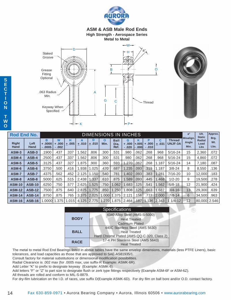
ASM & ASB Male Rod EndsHigh Strength - Aerospace Series
Metal to Metal
D a°
W
G
B
H
O
.063 RadiusMin.
G+ .000- .020
BallDia.Ref.
P+ .000- .010
DIMENSIONS IN INCHESW
+ .000- .002
RightHand
OMin.Left
Hand
P
Rod End No. a°
Misalign.
Angle
Min.
Ult.StaticRadialLoadLbs
14
C+ .031
ASM-3 ASB-3 .1900 .437 .337 1.562 .806 .300 .531 .980 .062 .268 .968 5/16-24 15 2,360 .072
ASM-4 ASB-4 .2500 .437 .337 1.562 .806 .300 .531 .980 .062 .268 .968 5/16-24 15 4,860 .072
ASM-5 ASB-5 .3125 .437 .327 1.875 .900 .360 .593 1.270 .062 .268 1.187 5/16-24 14 7,180 .087
ASM-6 ASB-6 .3750 .500 .416 1.938 1.025 .470 .687 1.235 .093 .319 1.187 3/8-24 8 8,550 .136
ASM-7 ASB-7 .4375 .562 .452 2.125 1.150 .540 .781 1.402 .093 .383 1.281 7/16-20 10 12,000 .183
ASM-8 ASB-8 .5000 .625 .515 2.438 1.337 .610 .875 1.589 .093 .445 1.468 1/2-20 9 19,500 .278
ASM-10 ASB-10 .6250 .750 .577 2.625 1.525 .750 1.062 1.683 .125 .541 1.562 5/8-18 12 21,900 .424
ASM-12 ASB-12 .7500 .875 .640 2.875 1.775 .850 1.250 1.808 .125 .663 1.687 3/4-16 13 29,300 .639
ASM-14 ASB-14 .8750 .875 .765 3.375 2.025 1.000 1.375 2.121 .156 .777 2.000 7/8-14 6 34,500 .963
ASM-16 ASB-16 1.0000 1.375 1.015 4.125 2.775 1.270 1.875 2.464 .187 1.136 2.343 1 1/4-12 12 80,000 2.546
K
A
C ThreadKeyway When
Specified
StakedGroove
K+.005- .000
A+ .010
Specifications4340 Alloy Steel (AMS-S-5000)
Heat TreatedCadmium Plated
440C Stainless Steel (AMS 5630)Heat Treated
Hard Chrome Plated (AMS-QQ-C-320, Class 2)17-4 PH Stainless Steel (AMS 5643)
Heat Treated
BODY
BALL
RACE
The metal to metal Rod End Bearings listed in above tables have the same envelop dimensions, materials (less PTFE Liners), basictolerances, and load capacities as those that are approved to SAE-AS81935/1.Consult factory for material substitutions or dimensional modification possibilities.Radial Clearance is .002 max (for .0005 max, use suffix-R Example: ASMK-6R).Add Letter “K” to prefix to designate keyway (Example: ASMK-6).Add letters “F” or “Z” to part size to designate flush or zerk type fittings respectively (Example ASM-6F or ASM-6Z).All threads are rolled and conform to MIL-S-8879.For dry-film lubrication on the I.D. of races, use suffix D(Example ASMK-6D). For dry film on ball bore and/or O.D. contact factory.
GreaseFitting
OptionalSECTION
TWO
Approx.
Brg.
Wt.
Lbs.
Ult.StaticRadialLoadLbs.
Fax 630-859-0971 • Aurora Bearing Company • Aurora, Illinois 60506 • www.aurorabearing.com
ThreadUNJF-3B
D+ .010
H+ .005
B+.0000- .0005
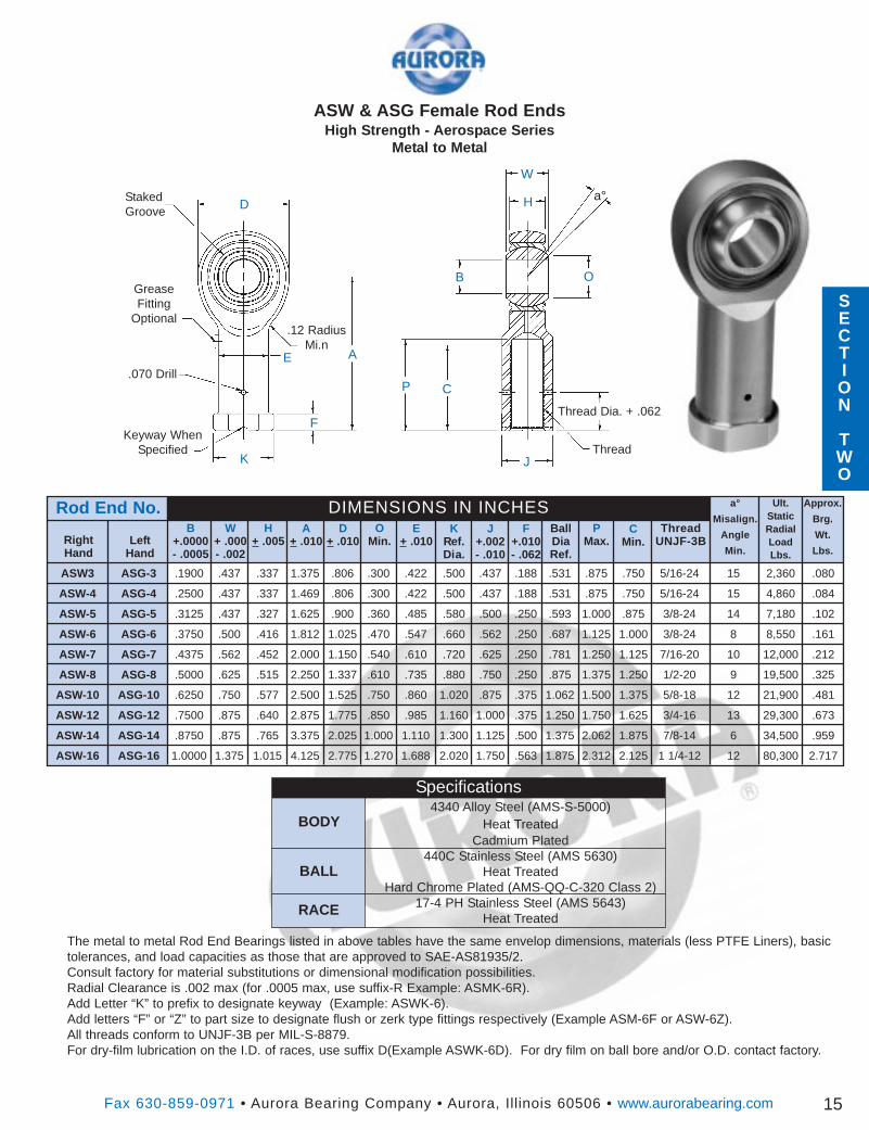
ASW & ASG Female Rod EndsHigh Strength - Aerospace Series
Metal to Metal
Da°
W
E
B
H
OGreaseFitting
Optional
J+.002- .010
KRef.Dia.
PMax.
DIMENSIONS IN INCHESW
+ .000- .002
RightHand
OMin.Left
Hand
P
Rod End No. a°
Misalign.
Angle
Min.
15
CMin.
ASW3 ASG-3 .1900 .437 .337 1.375 .806 .300 .422 .500 .437 .188 .531 .875 .750 5/16-24 15 2,360 .080
ASW-4 ASG-4 .2500 .437 .337 1.469 .806 .300 .422 .500 .437 .188 .531 .875 .750 5/16-24 15 4,860 .084
ASW-5 ASG-5 .3125 .437 .327 1.625 .900 .360 .485 .580 .500 .250 .593 1.000 .875 3/8-24 14 7,180 .102
ASW-6 ASG-6 .3750 .500 .416 1.812 1.025 .470 .547 .660 .562 .250 .687 1.125 1.000 3/8-24 8 8,550 .161
ASW-7 ASG-7 .4375 .562 .452 2.000 1.150 .540 .610 .720 .625 .250 .781 1.250 1.125 7/16-20 10 12,000 .212
ASW-8 ASG-8 .5000 .625 .515 2.250 1.337 .610 .735 .880 .750 .250 .875 1.375 1.250 1/2-20 9 19,500 .325
ASW-10 ASG-10 .6250 .750 .577 2.500 1.525 .750 .860 1.020 .875 .375 1.062 1.500 1.375 5/8-18 12 21,900 .481
ASW-12 ASG-12 .7500 .875 .640 2.875 1.775 .850 .985 1.160 1.000 .375 1.250 1.750 1.625 3/4-16 13 29,300 .673
ASW-14 ASG-14 .8750 .875 .765 3.375 2.025 1.000 1.110 1.300 1.125 .500 1.375 2.062 1.875 7/8-14 6 34,500 .959
ASW-16 ASG-16 1.0000 1.375 1.015 4.125 2.775 1.270 1.688 2.020 1.750 .563 1.875 2.312 2.125 1 1/4-12 12 80,300 2.717
K
A
C
ThreadKeyway When
Specified
StakedGroove
F+.010- .062
A+ .010
E+ .010
BallDiaRef.
J
F
.070 Drill
Thread Dia. + .062
Specifications4340 Alloy Steel (AMS-S-5000)
Heat TreatedCadmium Plated
440C Stainless Steel (AMS 5630)Heat Treated
Hard Chrome Plated (AMS-QQ-C-320 Class 2)17-4 PH Stainless Steel (AMS 5643)
Heat Treated
BODY
BALL
RACE
The metal to metal Rod End Bearings listed in above tables have the same envelop dimensions, materials (less PTFE Liners), basictolerances, and load capacities as those that are approved to SAE-AS81935/2.Consult factory for material substitutions or dimensional modification possibilities.Radial Clearance is .002 max (for .0005 max, use suffix-R Example: ASMK-6R).Add Letter “K” to prefix to designate keyway (Example: ASWK-6).Add letters “F” or “Z” to part size to designate flush or zerk type fittings respectively (Example ASM-6F or ASW-6Z).All threads conform to UNJF-3B per MIL-S-8879.For dry-film lubrication on the I.D. of races, use suffix D(Example ASWK-6D). For dry film on ball bore and/or O.D. contact factory.
.12 RadiusMi.n
SECTION
TWO
Fax 630-859-0971 • Aurora Bearing Company • Aurora, Illinois 60506 • www.aurorabearing.com
Static LimitLoad
D+.0000- .0005
H+.005
B+.0000- .0005
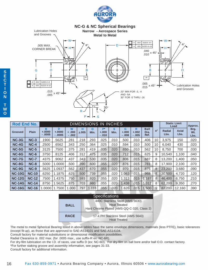
NC-G & NC Spherical BearingsNarrow - Aerospace Series
Metal to Metal
D a°W
G B
H
O
.005
.015
G+.000- .008
BallDia.Ref.
P*+.000- .010
DIMENSIONS IN INCHESW
+ .000- .002
GroovedO
Min.S
Min.Plain
SP
Rod End No.a°
16
RadialLbs.
AxialLbs.
NC-16G NC-16 1.0000 1.7500 1.000 .797 1.118 .055 .020 1.626 .015 1.500 9 82,200 12,160 .390
NC-12G NC-12 .7500 1.4375 .750 .593 .920 .055 .020 1.313 .015 1.187 8 46,400 6,750 .210NC-10G NC-10 .6250 1.1875 .625 .500 .739 .055 .020 1.063 .015 .968 8 30,500 4,720 .120NC-9G NC-9 .5625 1.0937 .562 .437 .670 .055 .020 .970 .015 .875 8 23,200 3,680 .090NC-8G NC-8 .5000 1.0000 .500 .390 .600 .055 .020 .876 .015 .781 8 17,900 2,100 .070NC-7G NC-7 .4375 .9062 .437 .343 .530 .035 .020 .806 .015 .687 8 13,200 1,400 .050NC-6G NC-6 .3750 .8125 .406 .312 .475 .035 .020 .712 .015 .625 9 10,540 1,100 .040NC-5G NC-5 .3125 .7500 .375 .281 .419 .035 .020 .650 .010 .562 10 8,750 700 .030NC-4G NC-4 .2500 .6562 .343 .250 .364 .025 .010 .594 .010 .500 10 6,040 430 .020NC-3G NC-3 .1900 .5625 .281 .218 .293 .025 .010 .500 .010 .406 10 3,975 150 .020
B O
W
Ha°
x 45°
.015
.005x 45°
30°
.005 MAX.CORNER BREAK
Approx.Brg.Wt.Lbs.
R+.002- .005
The metal to metal Spherical Bearing listed in above tables have the same envelope dimensions, materials (less PTFE), basic tolerances(except fit-up), as those that are approved to SAE-AS14101 and SAE-AS14104.Consult factory for material substitutions or dimensional modification possibilities.Radial Clearance is .002 max. (for .0005 max., use suffix-R ex: NC-6R).For dry-film lubrication on the I.D. of races, use suffix D (ex: NC-6D). For dry-film on ball bore and/or ball O.D. contact factory.*For further staking groove and assembly information, see pages 31-33.Consult factory for additional information.
R
Lubrication Holesand Grooves
.040
.010x 45°
A .003 SIZES 3-5
A .005 SIZES 6-16
A .003 SIZES 3-5
A .005 SIZES 6-16
-A- -A-
20° MIN FOR -3, -4AND -5A30° FOR -5 THRU -16
Lubrication Holesand Grooves
SECTION
TWO
SECTION
TWO
NC-14G NC-14 .8750 1.5625 .875 .703 .980 .055 .020 1.438 .015 1.312 8 62,200 9,350 .270
BALL
RACE
Specifications440C Stainless Steel (AMS 5630)
Heat TreatedHard Chrome Plated (AMS-QQ-C-320, Class 2)
17-4 PH Stainless Steel (AMS 5643)Heat Treated
Fax 630-859-0971 • Aurora Bearing Company • Aurora, Illinois 60506 • www.aurorabearing.com
Static LimitLoad
D+.0000- .0005
H+.005
B+.0000- .0005
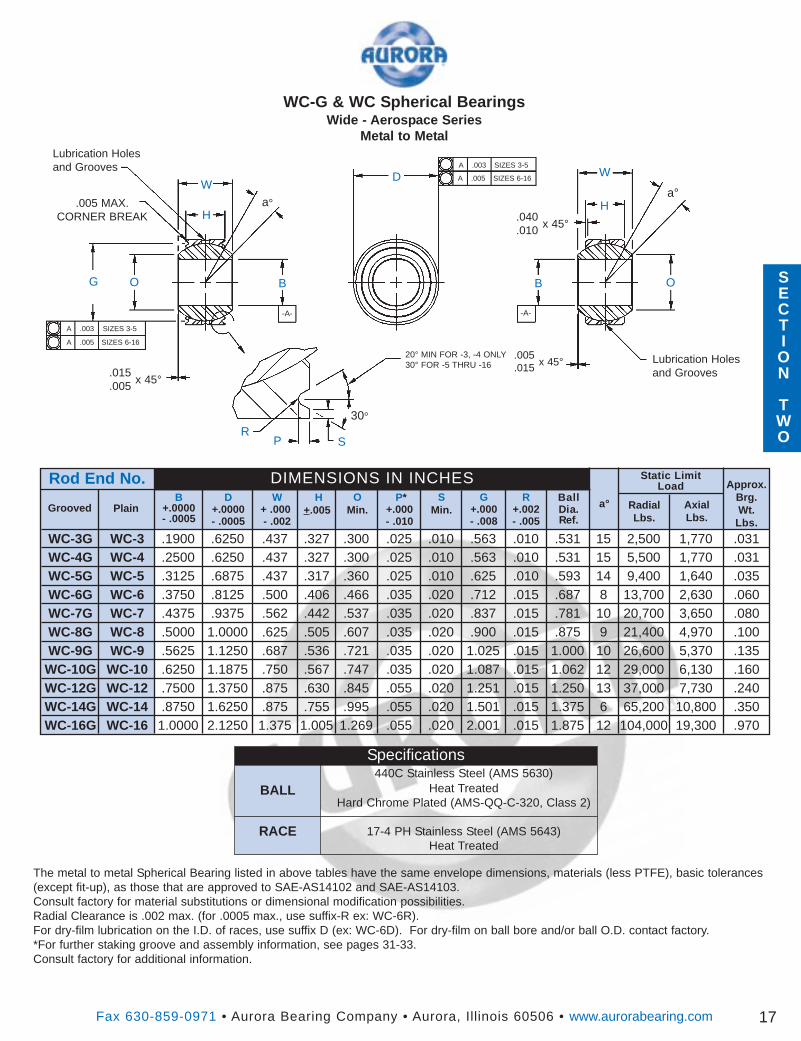
WC-G & WC Spherical BearingsWide - Aerospace Series
Metal to Metal
Da°
W
G B
H
O
.005
.015
G+.000- .008
BallDia.Ref.
P*+.000- .010
DIMENSIONS IN INCHESW
+ .000- .002
GroovedO
Min.S
Min.Plain
SP
Rod End No.a°
17
RadialLbs.
AxialLbs.
WC-16G WC-16 1.0000 2.1250 1.375 1.005 1.269 .055 .020 2.001 .015 1.875 12 104,000 19,300 .970WC-14G WC-14 .8750 1.6250 .875 .755 .995 .055 .020 1.501 .015 1.375 6 65,200 10,800 .350WC-12G WC-12 .7500 1.3750 .875 .630 .845 .055 .020 1.251 .015 1.250 13 37,000 7,730 .240WC-10G WC-10 .6250 1.1875 .750 .567 .747 .035 .020 1.087 .015 1.062 12 29,000 6,130 .160WC-9G WC-9 .5625 1.1250 .687 .536 .721 .035 .020 1.025 .015 1.000 10 26,600 5,370 .135WC-8G WC-8 .5000 1.0000 .625 .505 .607 .035 .020 .900 .015 .875 9 21,400 4,970 .100WC-7G WC-7 .4375 .9375 .562 .442 .537 .035 .020 .837 .015 .781 10 20,700 3,650 .080WC-6G WC-6 .3750 .8125 .500 .406 .466 .035 .020 .712 .015 .687 8 13,700 2,630 .060WC-5G WC-5 .3125 .6875 .437 .317 .360 .025 .010 .625 .010 .593 14 9,400 1,640 .035WC-4G WC-4 .2500 .6250 .437 .327 .300 .025 .010 .563 .010 .531 15 5,500 1,770 .031WC-3G WC-3 .1900 .6250 .437 .327 .300 .025 .010 .563 .010 .531 15 2,500 1,770 .031
B O
W
Ha°
x 45°.015.005
x 45°
30°
.005 MAX.CORNER BREAK
Approx.Brg.Wt.Lbs.
R+.002- .005
BALL
RACE
The metal to metal Spherical Bearing listed in above tables have the same envelope dimensions, materials (less PTFE), basic tolerances(except fit-up), as those that are approved to SAE-AS14102 and SAE-AS14103.Consult factory for material substitutions or dimensional modification possibilities.Radial Clearance is .002 max. (for .0005 max., use suffix-R ex: WC-6R).For dry-film lubrication on the I.D. of races, use suffix D (ex: WC-6D). For dry-film on ball bore and/or ball O.D. contact factory.*For further staking groove and assembly information, see pages 31-33.Consult factory for additional information.
R
Lubrication Holesand Grooves
.040
.010x 45°
A .003 SIZES 3-5
A .005 SIZES 6-16
A .003 SIZES 3-5
A .005 SIZES 6-16
-A- -A-
20° MIN FOR -3, -4 ONLY30° FOR -5 THRU -16
Specifications440C Stainless Steel (AMS 5630)
Heat TreatedHard Chrome Plated (AMS-QQ-C-320, Class 2)
17-4 PH Stainless Steel (AMS 5643)Heat Treated
Lubrication Holesand Grooves
SECTION
TWO
DW
A
B
H
C
PTFE Liner(AT 3200)Bonded toRace I.D.
Thread
O
RightHand
B+.0000- .0005
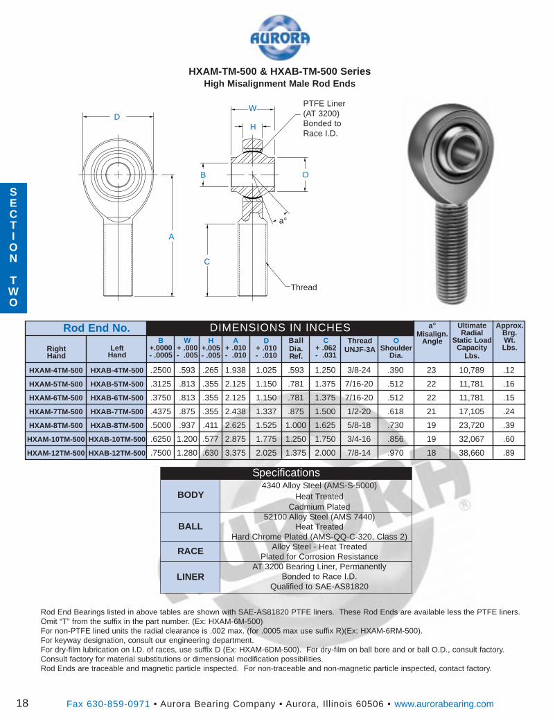
HXAM-4TM-500 HXAB-4TM-500 .2500 .593 .265 1.938 1.025 .593 1.250 3/8-24 .390 23 10,789 .12
HXAM-5TM-500 HXAB-5TM-500 .3125 .813 .355 2.125 1.150 .781 1.375 7/16-20 .512 22 11,781 .16
HXAM-6TM-500 HXAB-6TM-500 .3750 .813 .355 2.125 1.150 .781 1.375 7/16-20 .512 22 11,781 .15
HXAM-7TM-500 HXAB-7TM-500 .4375 .875 .355 2.438 1.337 .875 1.500 1/2-20 .618 21 17,105 .24
HXAM-8TM-500 HXAB-8TM-500 .5000 .937 .411 2.625 1.525 1.000 1.625 5/8-18 .730 19 23,720 .39
HXAM-10TM-500 HXAB-10TM-500 .6250 1.200 .577 2.875 1.775 1.250 1.750 3/4-16 .856 19 32,067 .60
HXAM-12TM-500 HXAB-12TM-500 .7500 1.280 .630 3.375 2.025 1.375 2.000 7/8-14 .970 18 38,660 .89
HXAM-TM-500 & HXAB-TM-500 SeriesHigh Misalignment Male Rod Ends
ThreadUNJF-3A
C+ .062- .031
BallDia.Ref.
D+ .010- .010
A+ .010- .010
H+.005- .005
UltimateRadial
Static LoadCapacity
Lbs.
Approx.Brg.Wt.Lbs.
Rod End No. DIMENSIONS IN INCHESW
+ .000- .005
LeftHand
a°Misalign.
Angle
Fax 630-859-0971 • Aurora Bearing Company • Aurora, Illinois 60506 • www.aurorabearing.com18
OShoulder
Dia.
a°
BODY
BALL
RACE
LINER
Specifications4340 Alloy Steel (AMS-S-5000)
Heat TreatedCadmium Plated
52100 Alloy Steel (AMS 7440)Heat Treated
Hard Chrome Plated (AMS-QQ-C-320, Class 2)Alloy Steel - Heat Treated
Plated for Corrosion ResistanceAT 3200 Bearing Liner, Permanently
Bonded to Race I.D.Qualified to SAE-AS81820
Rod End Bearings listed in above tables are shown with SAE-AS81820 PTFE liners. These Rod Ends are available less the PTFE liners.Omit “T” from the suffix in the part number. (Ex: HXAM-6M-500)For non-PTFE lined units the radial clearance is .002 max. (for .0005 max use suffix R)(Ex: HXAM-6RM-500).For keyway designation, consult our engineering department.For dry-film lubrication on I.D. of races, use suffix D (Ex: HXAM-6DM-500). For dry-film on ball bore and or ball O.D., consult factory.Consult factory for material substitutions or dimensional modification possibilities.Rod Ends are traceable and magnetic particle inspected. For non-traceable and non-magnetic particle inspected, contact factory.
SECTION
TWO
SECTION
TWO
SECTION
TWO
a°Misalign.
Angle
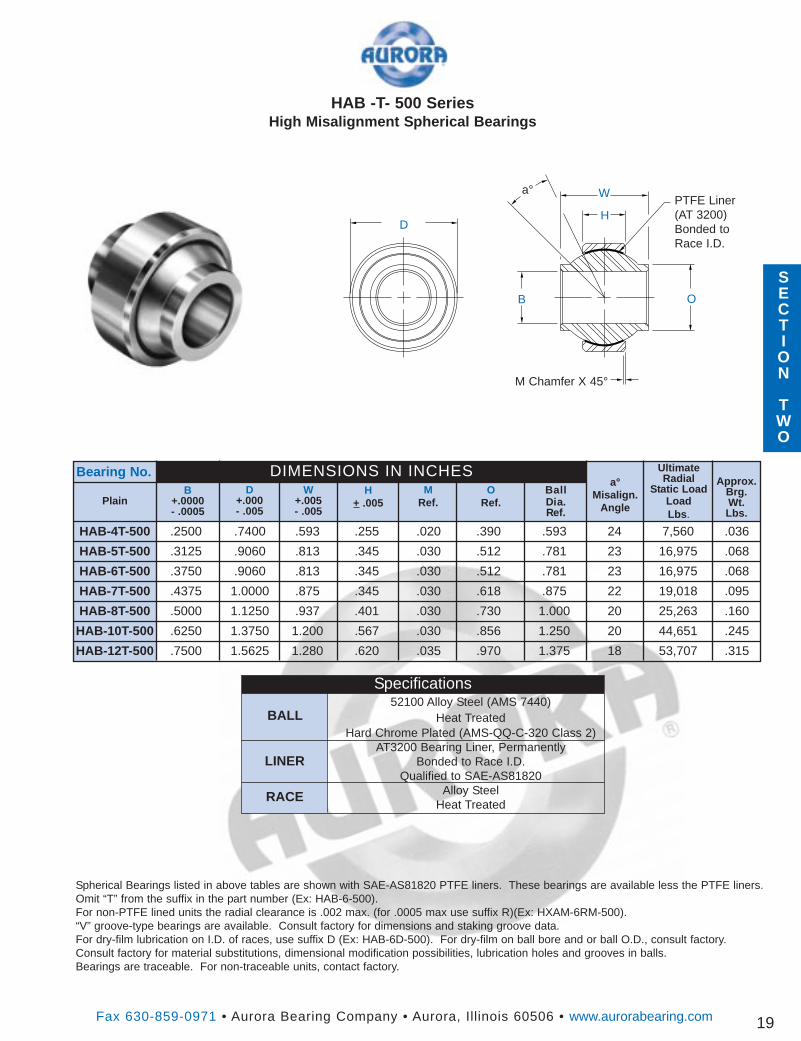
HAB -T- 500 SeriesHigh Misalignment Spherical Bearings
ORef.
BallDia.Ref.
D+.000- .005
MRef.
H+ .005
W+.005- .005
Bearing No.B
+.0000- .0005
Plain
Fax 630-859-0971 • Aurora Bearing Company • Aurora, Illinois 60506 • www.aurorabearing.com
UltimateRadial
Static LoadLoadLbs .
Approx.Brg.Wt.Lbs.
DIMENSIONS IN INCHES
19
B
W
HD
O
M Chamfer X 45°
PTFE Liner(AT 3200)Bonded toRace I.D.
a°
HAB-4T-500 .2500 .7400 .593 .255 .020 .390 .593 24 7,560 .036
HAB-5T-500 .3125 .9060 .813 .345 .030 .512 .781 23 16,975 .068
HAB-6T-500 .3750 .9060 .813 .345 .030 .512 .781 23 16,975 .068
HAB-7T-500 .4375 1.0000 .875 .345 .030 .618 .875 22 19,018 .095
HAB-8T-500 .5000 1.1250 .937 .401 .030 .730 1.000 20 25,263 .160
HAB-10T-500 .6250 1.3750 1.200 .567 .030 .856 1.250 20 44,651 .245
HAB-12T-500 .7500 1.5625 1.280 .620 .035 .970 1.375 18 53,707 .315
Specifications52100 Alloy Steel (AMS 7440)
Heat TreatedHard Chrome Plated (AMS-QQ-C-320 Class 2)
AT3200 Bearing Liner, PermanentlyBonded to Race I.D.
Qualified to SAE-AS81820Alloy Steel
Heat Treated
BALL
LINER
RACE
Spherical Bearings listed in above tables are shown with SAE-AS81820 PTFE liners. These bearings are available less the PTFE liners.Omit “T” from the suffix in the part number (Ex: HAB-6-500).For non-PTFE lined units the radial clearance is .002 max. (for .0005 max use suffix R)(Ex: HXAM-6RM-500).“V” groove-type bearings are available. Consult factory for dimensions and staking groove data.For dry-film lubrication on I.D. of races, use suffix D (Ex: HAB-6D-500). For dry-film on ball bore and or ball O.D., consult factory.Consult factory for material substitutions, dimensional modification possibilities, lubrication holes and grooves in balls.Bearings are traceable. For non-traceable units, contact factory.
Ultimate
Radial
Static
Load
Capacity
Fax 630-859-0971 • Aurora Bearing Company • Aurora, Illinois 60506 • www.aurorabearing.com
D+.010
H+.005
B+.0015-.0005
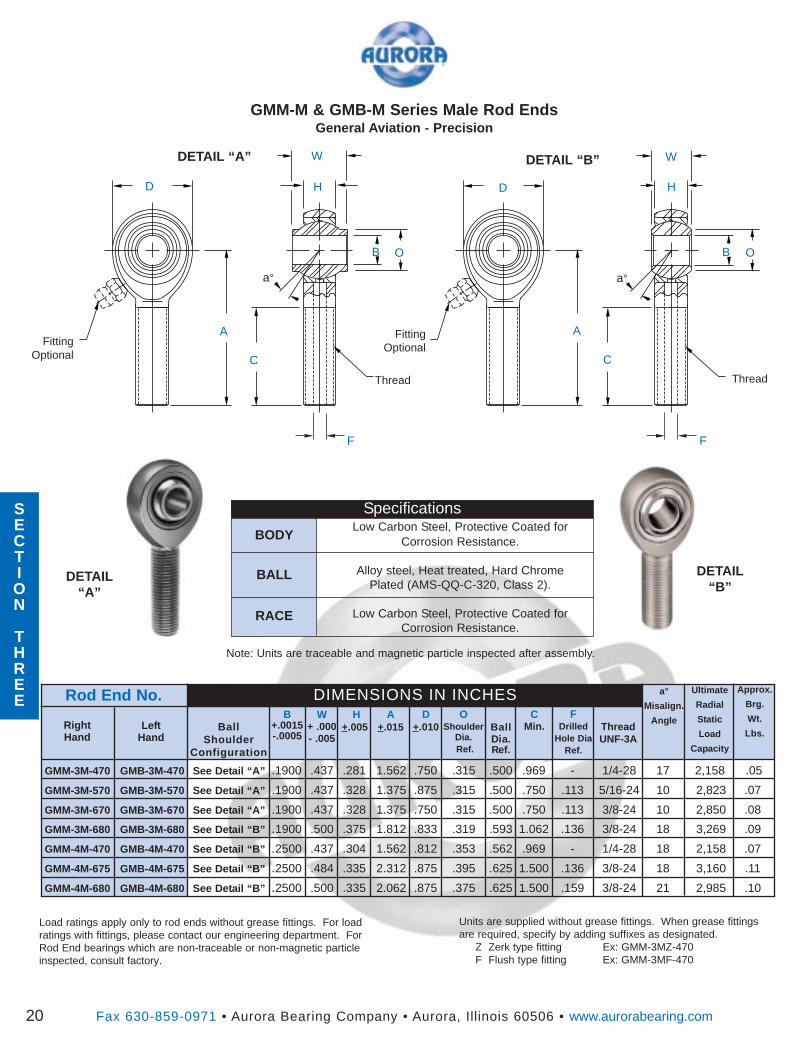
GMM-M & GMB-M Series Male Rod EndsGeneral Aviation - Precision
D
a°
W
D
B
H
O
BallDia.Ref.
DIMENSIONS IN INCHESW
+ .000- .005
RightHand
OShoulder
Dia.Ref.
A+.015Left
Hand
F
C
Rod End No. a°
Misalign.
Angle
20
FDrilled
Hole DiaRef.
ThreadUNF-3A
GMM-3M-470 GMB-3M-470 See Detail “A” .1900 .437 .281 1.562 .750 .315 .500 .969 - 1/4-28 17 2,158 .05
GMM-3M-570 GMB-3M-570 See Detail “A” .1900 .437 .328 1.375 .875 .315 .500 .750 .113 5/16-24 10 2,823 .07
GMM-3M-670 GMB-3M-670 See Detail “A” .1900 .437 .328 1.375 .750 .315 .500 .750 .113 3/8-24 10 2,850 .08
GMM-3M-680 GMB-3M-680 See Detail “B” .1900 .500 .375 1.812 .833 .319 .593 1.062 .136 3/8-24 18 3,269 .09
GMM-4M-470 GMB-4M-470 See Detail “B” .2500 .437 .304 1.562 .812 .353 .562 .969 - 1/4-28 18 2,158 .07
GMM-4M-675 GMB-4M-675 See Detail “B” .2500 .484 .335 2.312 .875 .395 .625 1.500 .136 3/8-24 18 3,160 .11
GMM-4M-680 GMB-4M-680 See Detail “B” .2500 .500 .335 2.062 .875 .375 .625 1.500 .159 3/8-24 21 2,985 .10
B O
W
H
a°
Thread
Approx.
Brg.
Wt.
Lbs.
CMin.
F
FittingOptional
Units are supplied without grease fittings. When grease fittingsare required, specify by adding suffixes as designated.
Z Zerk type fitting Ex: GMM-3MZ-470F Flush type fitting Ex: GMM-3MF-470
Load ratings apply only to rod ends without grease fittings. For loadratings with fittings, please contact our engineering department. ForRod End bearings which are non-traceable or non-magnetic particleinspected, consult factory.
Note: Units are traceable and magnetic particle inspected after assembly.
DETAIL“A”
DETAIL“B”
C
A AFittingOptional
Thread
BallShoulder
Configuration
DETAIL “A” DETAIL “B”
BODY
BALL
RACE
SpecificationsLow Carbon Steel, Protective Coated for
Corrosion Resistance.
Alloy steel, Heat treated, Hard ChromePlated (AMS-QQ-C-320, Class 2).
Low Carbon Steel, Protective Coated forCorrosion Resistance.
SECTION
THREE
DETAIL“B”
Note: Units are traceable and magnetic particle inspected after assembly.
Ultimate
Radial
Static
Load
Capacity
Fax 630-859-0971 • Aurora Bearing Company • Aurora, Illinois 60506 • www.aurorabearing.com
D
+.010
H
+.005
B
+.0015- .0005
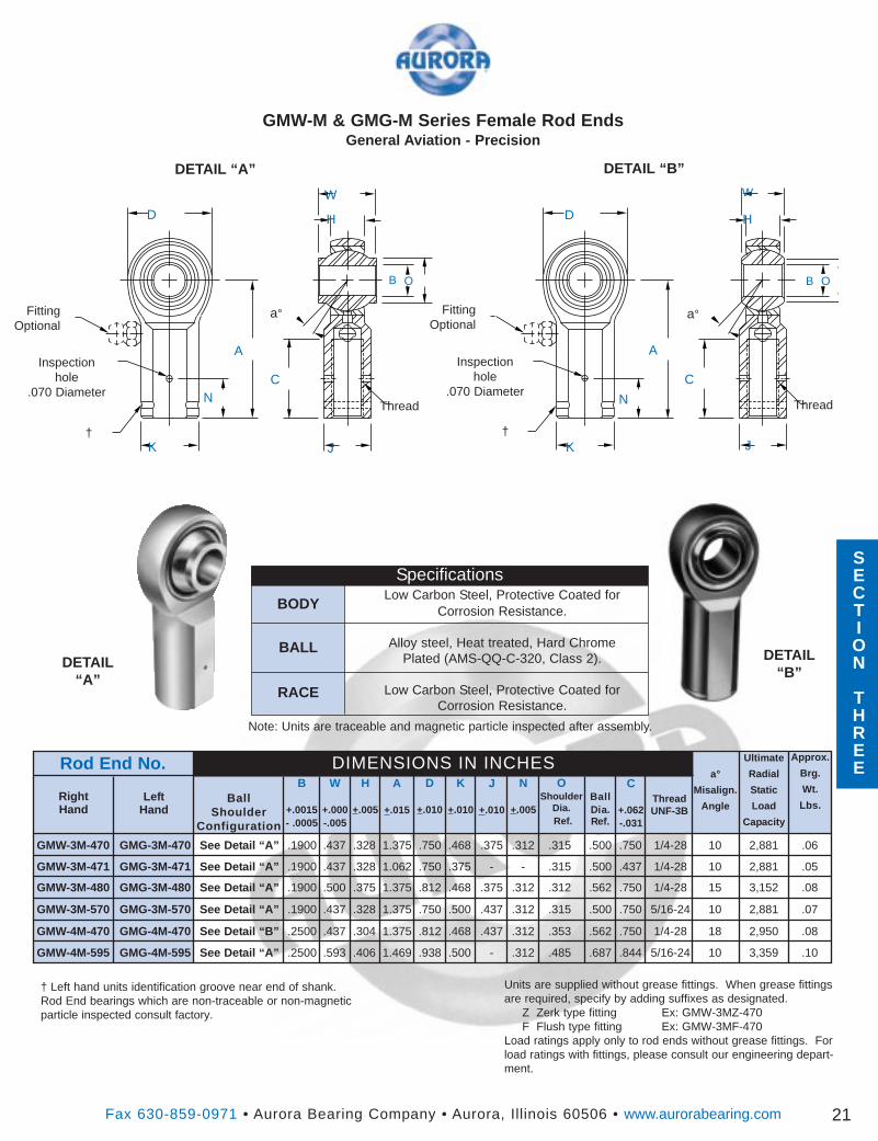
GMW-M & GMG-M Series Female Rod EndsGeneral Aviation - Precision
D
a°
W
D
B
H
O
BallDia.Ref.
DIMENSIONS IN INCHESW
+.000-.005
RightHand
OShoulder
Dia.Ref.
A
+.015Left
Hand
J
C
Rod End No.a°
Misalign.
Angle
21
C
+.062-.031
ThreadUNF-3B
GMW-3M-470 GMG-3M-470 See Detail “A” .1900 .437 .328 1.375 .750 .468 .375 .312 .315 .500 .750 1/4-28 10 2,881 .06
GMW-3M-471 GMG-3M-471 See Detail “A” .1900 .437 .328 1.062 .750 .375 - - .315 .500 .437 1/4-28 10 2,881 .05
GMW-3M-480 GMG-3M-480 See Detail “A” .1900 .500 .375 1.375 .812 .468 .375 .312 .312 .562 .750 1/4-28 15 3,152 .08
GMW-3M-570 GMG-3M-570 See Detail “A” .1900 .437 .328 1.375 .750 .500 .437 .312 .315 .500 .750 5/16-24 10 2,881 .07
GMW-4M-470 GMG-4M-470 See Detail “B” .2500 .437 .304 1.375 .812 .468 .437 .312 .353 .562 .750 1/4-28 18 2,950 .08
GMW-4M-595 GMG-4M-595 See Detail “A” .2500 .593 .406 1.469 .938 .500 - .312 .485 .687 .844 5/16-24 10 3,359 .10
B O
W
a°
Thread
Approx.
Brg.
Wt.
Lbs.
BODY
BALL
RACE
K
FittingOptional
Units are supplied without grease fittings. When grease fittingsare required, specify by adding suffixes as designated.
Z Zerk type fitting Ex: GMW-3MZ-470F Flush type fitting Ex: GMW-3MF-470
Load ratings apply only to rod ends without grease fittings. Forload ratings with fittings, please consult our engineering depart-ment.
† Left hand units identification groove near end of shank.Rod End bearings which are non-traceable or non-magneticparticle inspected consult factory.
DETAIL“A”
C
A A
FittingOptional
Thread
K
+.010
J
+.010
N
+.005Ball
ShoulderConfiguration
H
N
J K
N
††
Inspectionhole
.070 Diameter
Inspectionhole
.070 Diameter
DETAIL “A”
SpecificationsLow Carbon Steel, Protective Coated for
Corrosion Resistance.
Alloy steel, Heat treated, Hard ChromePlated (AMS-QQ-C-320, Class 2).
Low Carbon Steel, Protective Coated forCorrosion Resistance.
SECTION
THREE
DETAIL “B”
*
333
a°Misalign.
AngleMin.
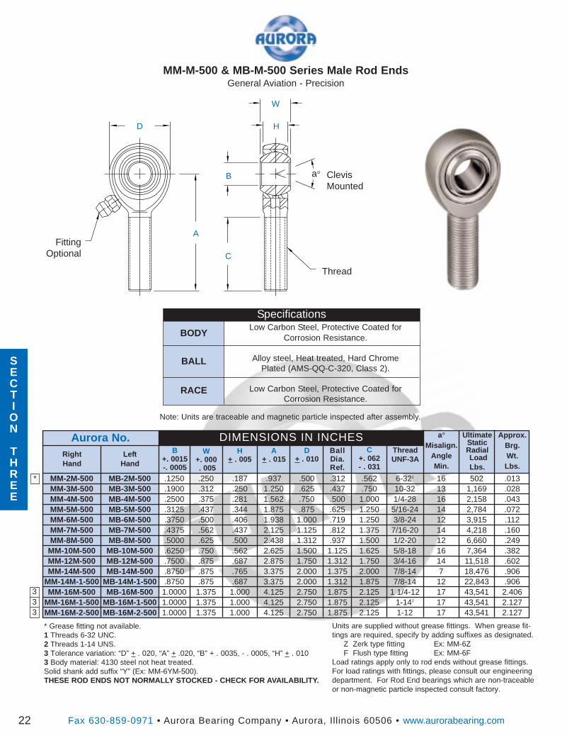
MM-M-500 & MB-M-500 Series Male Rod EndsGeneral Aviation - Precision
D
a° ClevisMounted
W
A
B
H
C
FittingOptional
Thread
ThreadUNF-3A
C+. 062- . 031
BallDia.Ref.
D+ . 010
A+ . 015
H+ . 005
W+. 000. 005
LeftHand
Aurora No.B
+. 0015-. 0005
Units are supplied without grease fittings. When grease fit-tings are required, specify by adding suffixes as designated.
Z Zerk type fitting Ex: MM-6ZF Flush type fitting Ex: MM-6F
Load ratings apply only to rod ends without grease fittings.For load ratings with fittings, please consult our engineeringdepartment. For Rod End bearings which are non-traceableor non-magnetic particle inspected consult factory.
* Grease fitting not available.1 Threads 6-32 UNC.2 Threads 1-14 UNS.3 Tolerance variation: “D” + . 020, “A” + .020, “B” + . 0035, - . 0005, “H” + . 0103 Body material: 4130 steel not heat treated.Solid shank add suffix “Y” (Ex: MM-6YM-500).THESE ROD ENDS NOT NORMALLY STOCKED - CHECK FOR AVAILABILITY.
RightHand
Fax 630-859-0971 • Aurora Bearing Company • Aurora, Illinois 60506 • www.aurorabearing.com
UltimateStaticRadialLoadLbs.
Approx.Brg.Wt.Lbs.
DIMENSIONS IN INCHES
22
MM-2M-500 MB-2M-500 .1250 .250 .187 .937 .500 .312 .562 6-321 16 502 .013MM-3M-500 MB-3M-500 .1900 .312 .250 1.250 .625 .437 .750 10-32 13 1,169 .028MM-4M-500 MB-4M-500 .2500 .375 .281 1.562 .750 .500 1.000 1/4-28 16 2,158 .043MM-5M-500 MB-5M-500 .3125 .437 .344 1.875 .875 .625 1.250 5/16-24 14 2,784 .072MM-6M-500 MB-6M-500 .3750 .500 .406 1.938 1.000 .719 1.250 3/8-24 12 3,915 .112MM-7M-500 MB-7M-500 .4375 .562 .437 2.125 1.125 .812 1.375 7/16-20 14 4,218 .160MM-8M-500 MB-8M-500 .5000 .625 .500 2.438 1.312 .937 1.500 1/2-20 12 6,660 .249
MM-10M-500 MB-10M-500 .6250 .750 .562 2.625 1.500 1.125 1.625 5/8-18 16 7,364 .382MM-12M-500 MB-12M-500 .7500 .875 .687 2.875 1.750 1.312 1.750 3/4-16 14 11,518 .602MM-14M-500 MB-14M-500 .8750 .875 .765 3.375 2.000 1.375 2.000 7/8-14 7 18,476 .906
MM-14M-1-500 MB-14M-1-500 .8750 .875 .687 3.375 2.000 1.312 1.875 7/8-14 12 22,843 .906MM-16M-500 MB-16M-500 1.0000 1.375 1.000 4.125 2.750 1.875 2.125 1 1/4-12 17 43,541 2.406
MM-16M-1-500 MB-16M-1-500 1.0000 1.375 1.000 4.125 2.750 1.875 2.125 1-142 17 43,541 2.127MM-16M-2-500 MB-16M-2-500 1.0000 1.375 1.000 4.125 2.750 1.875 2.125 1-12 17 43,541 2.127
BODY
BALL
RACE
SpecificationsLow Carbon Steel, Protective Coated for
Corrosion Resistance.
Alloy steel, Heat treated, Hard ChromePlated (AMS-QQ-C-320, Class 2).
Low Carbon Steel, Protective Coated forCorrosion Resistance.
Note: Units are traceable and magnetic particle inspected after assembly.
SECTION
THREE
SECTION
THREE
Approx.Brg.Wt.Lbs.
Fax 630-859-0971 • Aurora Bearing Company • Aurora, Illinois 60506 • www.aurorabearing.com
Ult.StaticRadialLoadLbs.
ThreadUNF-2B
D+ .010
H+ .005
B+.0015-.0005
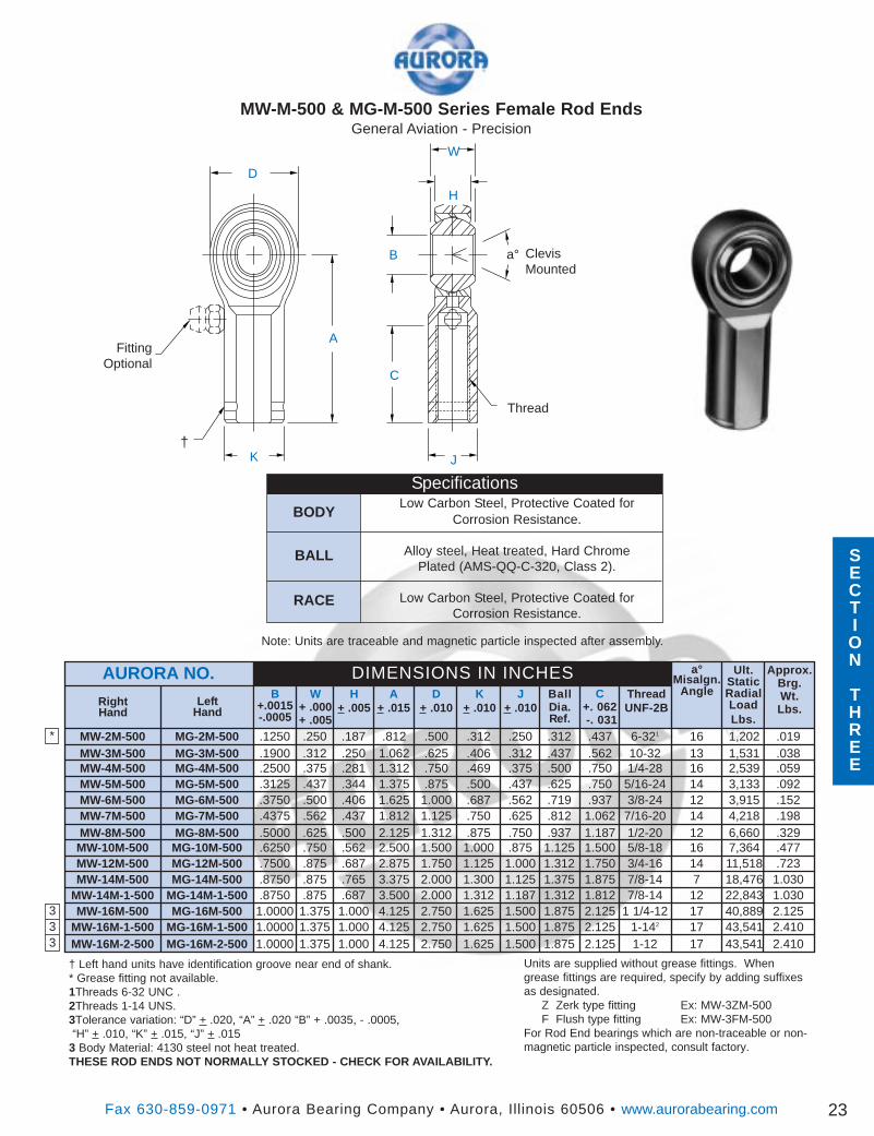
MW-M-500 & MG-M-500 Series Female Rod EndsGeneral Aviation - Precision
C+. 062-. 031
BallDia.Ref.
A+ .015
DIMENSIONS IN INCHESW
+ .000+ .005
RightHand
K+ .010
J+ .010Left
Hand
AURORA NO. a°Misalgn.
Angle
23
MW-2M-500 MG-2M-500 .1250 .250 .187 .812 .500 .312 .250 .312 .437 6-321 16 1,202 .019MW-3M-500 MG-3M-500 .1900 .312 .250 1.062 .625 .406 .312 .437 .562 10-32 13 1,531 .038MW-4M-500 MG-4M-500 .2500 .375 .281 1.312 .750 .469 .375 .500 .750 1/4-28 16 2,539 .059MW-5M-500 MG-5M-500 .3125 .437 .344 1.375 .875 .500 .437 .625 .750 5/16-24 14 3,133 .092MW-6M-500 MG-6M-500 .3750 .500 .406 1.625 1.000 .687 .562 .719 .937 3/8-24 12 3,915 .152MW-7M-500 MG-7M-500 .4375 .562 .437 1.812 1.125 .750 .625 .812 1.062 7/16-20 14 4,218 .198MW-8M-500 MG-8M-500 .5000 .625 .500 2.125 1.312 .875 .750 .937 1.187 1/2-20 12 6,660 .329
MW-10M-500 MG-10M-500 .6250 .750 .562 2.500 1.500 1.000 .875 1.125 1.500 5/8-18 16 7,364 .477MW-12M-500 MG-12M-500 .7500 .875 .687 2.875 1.750 1.125 1.000 1.312 1.750 3/4-16 14 11,518 .723MW-14M-500 MG-14M-500 .8750 .875 .765 3.375 2.000 1.300 1.125 1.375 1.875 7/8-14 7 18,476 1.030
MW-14M-1-500 MG-14M-1-500 .8750 .875 .687 3.500 2.000 1.312 1.187 1.312 1.812 7/8-14 12 22,843 1.030MW-16M-500 MG-16M-500 1.0000 1.375 1.000 4.125 2.750 1.625 1.500 1.875 2.125 1 1/4-12 17 40,889 2.125
MW-16M-1-500 MG-16M-1-500 1.0000 1.375 1.000 4.125 2.750 1.625 1.500 1.875 2.125 1-142 17 43,541 2.410MW-16M-2-500 MG-16M-2-500 1.0000 1.375 1.000 4.125 2.750 1.625 1.500 1.875 2.125 1-12 17 43,541 2.410
D
a° ClevisMounted
W
A
B
H
C
FittingOptional
Thread
JK
Units are supplied without grease fittings. Whengrease fittings are required, specify by adding suffixesas designated.
Z Zerk type fitting Ex: MW-3ZM-500F Flush type fitting Ex: MW-3FM-500
For Rod End bearings which are non-traceable or non-magnetic particle inspected, consult factory.
† Left hand units have identification groove near end of shank.* Grease fitting not available.1Threads 6-32 UNC .2Threads 1-14 UNS.3Tolerance variation: “D” + .020, “A” + .020 “B” + .0035, - .0005,“H” + .010, “K” + .015, “J” + .015
3 Body Material: 4130 steel not heat treated.THESE ROD ENDS NOT NORMALLY STOCKED - CHECK FOR AVAILABILITY.
BODY
BALL
RACE
SpecificationsLow Carbon Steel, Protective Coated for
Corrosion Resistance.
Alloy steel, Heat treated, Hard ChromePlated (AMS-QQ-C-320, Class 2).
Low Carbon Steel, Protective Coated forCorrosion Resistance.
Note: Units are traceable and magnetic particle inspected after assembly.
†
*
333
SECTION
THREE
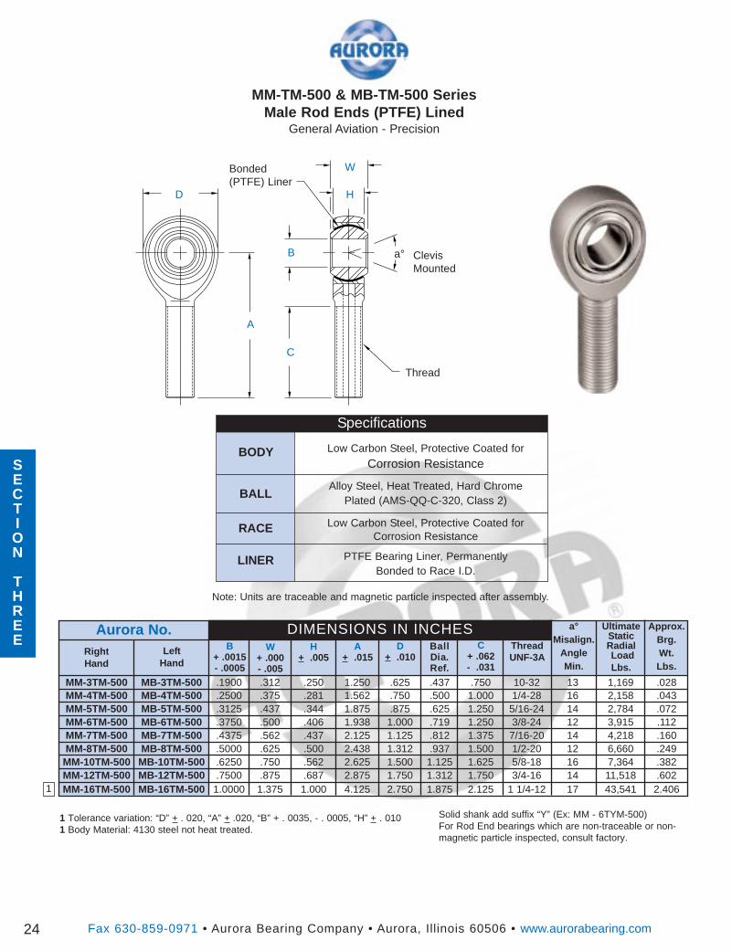
MM-TM-500 & MB-TM-500 SeriesMale Rod Ends (PTFE) Lined
General Aviation - Precision
Solid shank add suffix “Y” (Ex: MM - 6TYM-500)For Rod End bearings which are non-traceable or non-magnetic particle inspected, consult factory.
1 Tolerance variation: “D” + . 020, “A” + .020, “B” + . 0035, - . 0005, “H” + . 0101 Body Material: 4130 steel not heat treated.
Fax 630-859-0971 • Aurora Bearing Company • Aurora, Illinois 60506 • www.aurorabearing.com24
a°Misalign.
AngleMin.
ThreadUNF-3A
C+ .062- .031
BallDia.Ref.
D+ .010
A+ .015
H+ .005
W+ .000- .005
LeftHand
Aurora No.B
+ .0015- .0005
RightHand
UltimateStaticRadialLoadLbs.
Approx.Brg.Wt.Lbs.
DIMENSIONS IN INCHES
MM-3TM-500 MB-3TM-500 .1900 .312 .250 1.250 .625 .437 .750 10-32 13 1,169 .028MM-4TM-500 MB-4TM-500 .2500 .375 .281 1.562 .750 .500 1.000 1/4-28 16 2,158 .043MM-5TM-500 MB-5TM-500 .3125 .437 .344 1.875 .875 .625 1.250 5/16-24 14 2,784 .072MM-6TM-500 MB-6TM-500 .3750 .500 .406 1.938 1.000 .719 1.250 3/8-24 12 3,915 .112MM-7TM-500 MB-7TM-500 .4375 .562 .437 2.125 1.125 .812 1.375 7/16-20 14 4,218 .160MM-8TM-500 MB-8TM-500 .5000 .625 .500 2.438 1.312 .937 1.500 1/2-20 12 6,660 .249
MM-10TM-500 MB-10TM-500 .6250 .750 .562 2.625 1.500 1.125 1.625 5/8-18 16 7,364 .382MM-12TM-500 MB-12TM-500 .7500 .875 .687 2.875 1.750 1.312 1.750 3/4-16 14 11,518 .602MM-16TM-500 MB-16TM-500 1.0000 1.375 1.000 4.125 2.750 1.875 2.125 1 1/4-12 17 43,541 2.4061
D
a° ClevisMounted
W
A
B
H
C
Thread
Bonded(PTFE) Liner
BODY
RACE
LINER
Specifications
Low Carbon Steel, Protective Coated forCorrosion Resistance
Alloy Steel, Heat Treated, Hard ChromePlated (AMS-QQ-C-320, Class 2)
Low Carbon Steel, Protective Coated forCorrosion Resistance
PTFE Bearing Liner, PermanentlyBonded to Race I.D.
Note: Units are traceable and magnetic particle inspected after assembly.
SECTION
THREE
SECTION
THREE
BALL
D
a° ClevisMounted
W
A
B
H
C
Thread
JK
Bonded(PTFE) Liner
† Left hand units have identification groove near end of shank.For Rod End bearings which are non-traceable or non-magneticparticle inspected, consult factory.
Fax 630-859-0971 • Aurora Bearing Company • Aurora, Illinois 60506 • www.aurorabearing.com
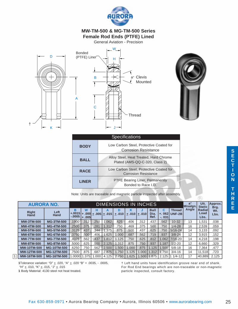
MW-TM-500 & MG-TM-500 SeriesFemale Rod Ends (PTFE) Lined
General Aviation - Precision
1Tolerance variation: “D” + .020, “A” + .020 “B” + .0035, - .0005,“H” + .010, “K” + .015, “J” + .015
1 Body Material: 4130 steel not heat treated.
25
BODY
BALL
RACE
LINER
Specifications
Low Carbon Steel, Protective Coated forCorrosion Resistance
Alloy Steel, Heat Treated, Hard ChromePlated (AMS-QQ-C-320, Class 2)
Low Carbon Steel, Protective Coated forCorrosion Resistance
PTFE Bearing Liner, PermanentlyBonded to Race I.D.
Approx.Brg.Wt.Lbs.
Ult.StaticRadialLoadLbs.
ThreadUNF-2B
D+ .010
H+ .005
B+.0015-.0005
C+. 062-. 031
BallDia.Ref.
A+ .015
DIMENSIONS IN INCHESW
+ .000+ .005
RightHand
K+ .010
J+ .010Left
Hand
AURORA NO. a°Misalgn.
Angle
MW-3TM-500 MG-3TM-500 .1900 .312 .250 1.062 .625 .406 .312 .437 .562 10-32 13 1,531 .038MW-4TM-500 MG-4TM-500 .2500 .375 .281 1.312 .750 .469 .375 .500 .750 1/4-28 16 2,539 .059MW-5TM-500 MG-5TM-500 .3125 .437 .344 1.375 .875 .500 .437 .625 .750 5/16-24 14 3,133 .092MW-6TM-500 MG-6TM-500 .3750 .500 .406 1.625 1.000 .687 .562 .719 .937 3/8-24 12 3,915 .152MW-7TM-500 MG-7TM-500 .4375 .562 .437 1.812 1.125 .750 .625 .812 1.062 7/16-20 14 4,218 .198MW-8TM-500 MG-8TM-500 .5000 .625 .500 2.125 1.312 .875 .750 .937 1.187 1/2-20 12 6,660 .329
MW-10TM-500 MG-10TM-500 .6250 .750 .562 2.500 1.500 1.000 .875 1.125 1.500 5/8-18 16 7,364 .477MW-12TM-500 MG-12TM-500 .7500 .875 .687 2.875 1.750 1.125 1.000 1.312 1.750 3/4-16 14 11,518 .723MW-16TM-500 MG-16TM-500 1.0000 1.375 1.000 4.125 2.750 1.625 1.500 1.875 2.125 1 1/4-12 17 40,889 2.125
†
Note: Units are traceable and magnetic particle inspected after assembly.
1
SECTION
THREE
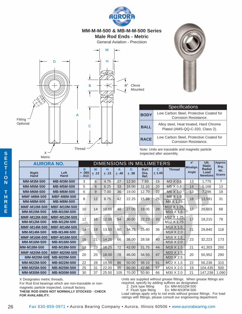
MM-M-M-500 & MB-M-M-500 SeriesMale Rod Ends - MetricGeneral Aviation - Precision
D
a° ClevisMounted
W
A
B
H
C
FittingOptional
Thread
Fax 630-859-0971 • Aurora Bearing Company • Aurora, Illinois 60506 • www.aurorabearing.com26
a°
Misalign.
AngleThreadC
+ 1.00BallDia.Ref.
D+ .38
A+ .40
H+ .13
W+ .13Left
Hand
AURORA NO.B
+ .065- .013
RightHand
Ult.StaticRadialLoad
Newtons
Approx.Brg.Wt.
Grams
DIMENSIONS IN MILLIMETERS
MM-M3M-500 MB-M3M-500 3 6 4.75 27 12.50 7.93 15 M3 X 0.5 13 1,775 7MM-M5M-500 MB-M5M-500 5 8 6.25 33 16.00 11.10 20 M5 X 0.8 14 5,168 13MM-M6M-500 MB-M6M-500 6 9 7.00 36 19.00 12.70 22 M6 X 1.0 13 7,296 18
MM-M8M-500 MB-M8M-5008 12 8.75 42 22.25 15.88 25
M8 X 1.2518 13,591 31
MM-M10M-500 MB-M10M-50010 14 10.50 48 27.00 19.05 29
M10 X 1.517 20,603 68
MM-M12M-500 MB-M12M-50012 16 12.00 54 30.00 22.23 33
M12 X 1.7517 18,215 78
MM-M14M-500 MB-M14M-50014 19 13.50 60 34.75 25.40 36
M14 X 2.021 29,840 118
MM-M16M-500 MB-M16M-50016 21 14.25 66 38.00 28.58 40
M16 X 2.023 32,223 173
MM-M18M-500 MB-M18M-500 18 23 16.25 72 42.00 31.75 44 M18 X 1.5 21 41,303 260
MM-M20M-500 MB-M20M-50020 25 18.00 78 46.00 34.93 47
M20 X 2.520 50,952 290
X Designates metric threads.For Rod End bearings which are non-traceable or non-magnetic particle inspected, consult factory.THESE ROD ENDS NOT NORMALLY STOCKED - CHECKFOR AVAILABILITY.
XMetric
MMF-M8M-500 MBF-M8M-500 M8 X 1.0
MMF-M10M-500 MBF-M10M-500 M10 X 1.25
MMF-M12M-500 MBF-M12M-500 M12 X 1.25
MMF-M14M-500 MBF-M14M-500 M14 X 1.5
MMF-M16M-500 MBF-M16M-500 M16 X 1.5
MMF-M20M-500 MBF-M20M-500 M20 X 1.5
MM-M22M-500 MB-M22M-500 22 28 19.50 86 50.00 38.10 51 M22 X 1.5 22 56,238 315MM-M25M-500 MB-M25M-500 25 31 22.00 95 60.00 42.86 57 M24 X 2.0 19 104,435 500MM-M30M-500 MB-M30M-500 30 37 25.50 105 70.00 50.80 66 M30 X 2.0 21 147,238 1,090
Units are supplied without grease fittings. When grease fittings arerequired, specify by adding suffixes as designated.
Z Zerk type fitting Ex: MM-M10ZM-500F Flush type fitting Ex: MM-M10FM-500
Load ratings apply only to rod ends without grease fittings. For loadratings with fittings, please consult our engineering department.
BODY
BALL
RACE
Note: Units are traceable and magnetic particleinspected after assembly.
SpecificationsLow Carbon Steel, Protective Coated for
Corrosion Resistance.
Alloy steel, Heat treated, Hard ChromePlated (AMS-QQ-C-320, Class 2).
Low Carbon Steel, Protective Coated forCorrosion Resistance.
SECTION
THREE
SECTION
THREE
a° ClevisMounted
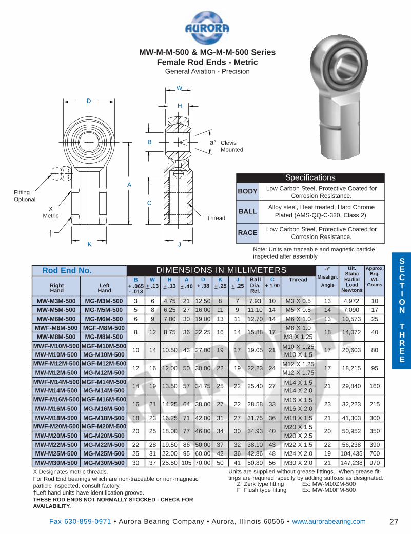
Fax 630-859-0971 • Aurora Bearing Company • Aurora, Illinois 60506 • www.aurorabearing.com 27
a°
Misalign.
AngleThreadC
+ 1.00BallDia.Ref.
D+ .38
A+ .40
H+ .13
W+ .13Left
Hand
Rod End No.B
+ .065- .013
RightHand
Ult.StaticRadialLoad
Newtons
Approx.Brg.Wt.
Grams
DIMENSIONS IN MILLIMETERS
MW-M3M-500 MG-M3M-500 3 6 4.75 21 12.50 8 7 7.93 10 M3 X 0.5 13 4,972 10
MW-M5M-500 MG-M5M-500 5 8 6.25 27 16.00 11 9 11.10 14 M5 X 0.8 14 7,090 17
MW-M6M-500 MG-M6M-500 6 9 7.00 30 19.00 13 11 12.70 14 M6 X 1.0 13 10,573 25
MW-M8M-500 MG-M8M-5008 12 8.75 36 22.25 16 14 15.88 17
M8 X 1.2518 14,072 40
MW-M10M-500 MG-M10M-50010 14 10.50 43 27.00 19 17 19.05 21
M10 X 1.517 20,603 80
MW-M12M-500 MG-M12M-50012 16 12.00 50 30.00 22 19 22.23 24
M12 X 1.7517 18,215 95
MW-M14M-500 MG-M14M-50014 19 13.50 57 34.75 25 22 25.40 27
M14 X 2.021 29,840 160
MW-M16M-500 MG-M16M-50016 21 14.25 64 38.00 27 22 28.58 33
M16 X 2.023 32,223 215
MW-M18M-500 MG-M18M-500 18 23 16.25 71 42.00 31 27 31.75 36 M18 X 1.5 21 41,303 300
MW-M20M-500 MG-M20M-50020 25 18.00 77 46.00 34 30 34.93 40
M20 X 2.520 50,952 350
FittingOptional
Thread
K+ .25
J+ .25
X Designates metric threads.For Rod End bearings which are non-traceable or non-magneticparticle inspected, consult factory.†Left hand units have identification groove.THESE ROD ENDS NOT NORMALLY STOCKED - CHECK FORAVAILABILITY.
XMetric
D
W
H
B
C
A
MW-M-M-500 & MG-M-M-500 SeriesFemale Rod Ends - Metric
General Aviation - Precision
JK
MWF-M8M-500 MGF-M8M-500 M8 X 1.0
MWF-M10M-500 MGF-M10M-500 M10 X 1.25
MWF-M12M-500 MGF-M12M-500 M12 X 1.25
MWF-M14M-500 MGF-M14M-500 M14 X 1.5
MWF-M16M-500 MGF-M16M-500 M16 X 1.5
MWF-M20M-500 MGF-M20M-500 M20 X 1.5
MW-M22M-500 MG-M22M-500 22 28 19.50 86 50.00 37 32 38.10 43 M22 X 1.5 22 56,238 390MW-M25M-500 MG-M25M-500 25 31 22.00 95 60.00 42 36 42.86 48 M24 X 2.0 19 104,435 700
MW-M30M-500 MG-M30M-500 30 37 25.50 105 70.00 50 41 50.80 56 M30 X 2.0 21 147,238 970
†
Units are supplied without grease fittings. When grease fit-tings are required, specify by adding suffixes as designated.
Z Zerk type fitting Ex: MW-M10ZM-500F Flush type fitting Ex: MW-M10FM-500
BODY
BALL
RACE
Note: Units are traceable and magnetic particleinspected after assembly.
SpecificationsLow Carbon Steel, Protective Coated for
Corrosion Resistance.
Alloy steel, Heat treated, Hard ChromePlated (AMS-QQ-C-320, Class 2).
Low Carbon Steel, Protective Coated forCorrosion Resistance.
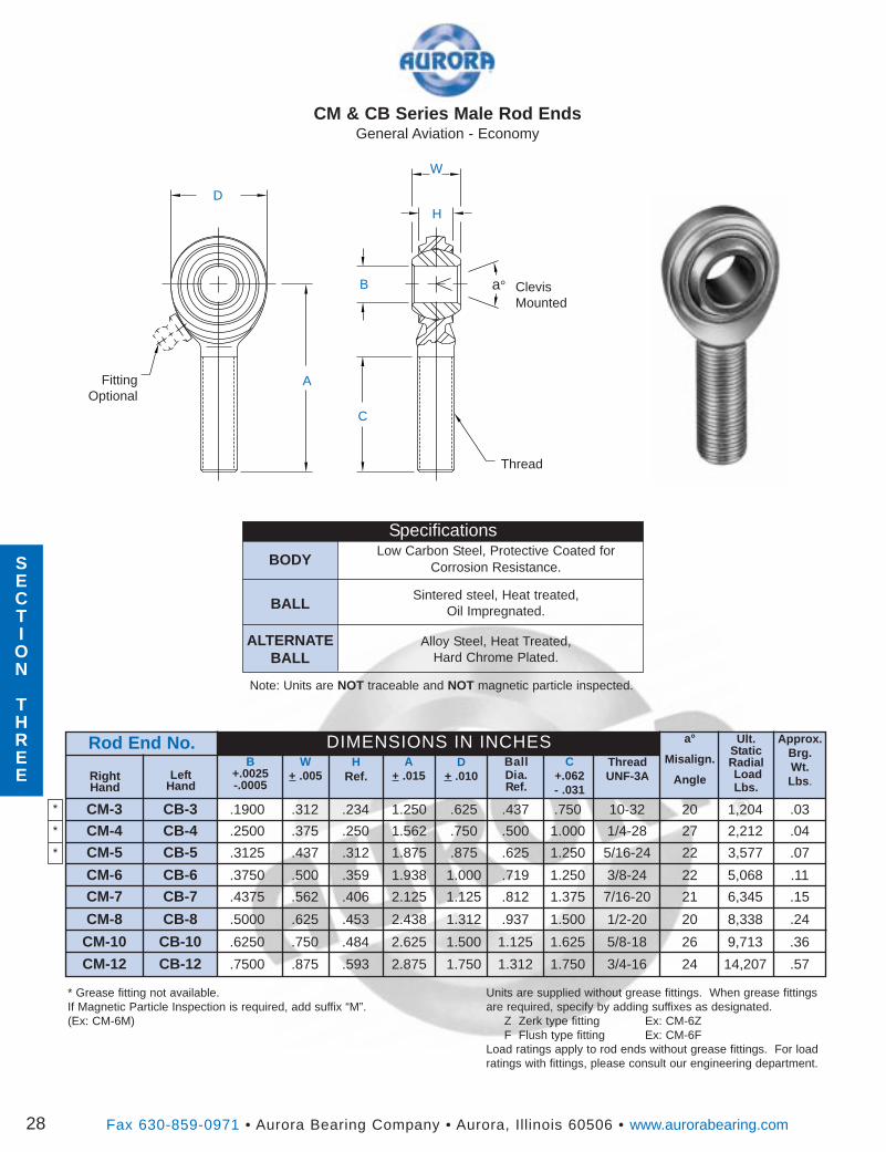
CM-6 CB-6 .3750 .500 .359 1.938 1.000 .719 1.250 3/8-24 22 5,068 .11
RightHand
B+.0025-.0005
CM-10 CB-10 .6250 .750 .484 2.625 1.500 1.125 1.625 5/8-18 26 9,713 .36
CM & CB Series Male Rod EndsGeneral Aviation - Economy
D
a° ClevisMounted
W
A
B
H
C
FittingOptional
Thread
CM-3 CB-3 .1900 .312 .234 1.250 .625 .437 .750 10-32 20 1,204 .03
CM-4 CB-4 .2500 .375 .250 1.562 .750 .500 1.000 1/4-28 27 2,212 .04
CM-7 CB-7 .4375 .562 .406 2.125 1.125 .812 1.375 7/16-20 21 6,345 .15
CM-8 CB-8 .5000 .625 .453 2.438 1.312 .937 1.500 1/2-20 20 8,338 .24
CM-12 CB-12 .7500 .875 .593 2.875 1.750 1.312 1.750 3/4-16 24 14,207 .57
CM-5 CB-5 .3125 .437 .312 1.875 .875 .625 1.250 5/16-24 22 3,577 .07
ThreadUNF-3A
C+.062- .031
BallDia.Ref.
D+ .010
A+ .015
HRef.
Ult.StaticRadialLoadLbs.
Approx.Brg.Wt.Lbs .
Rod End No. DIMENSIONS IN INCHESW
+ .005
Units are supplied without grease fittings. When grease fittingsare required, specify by adding suffixes as designated.
Z Zerk type fitting Ex: CM-6ZF Flush type fitting Ex: CM-6F
Load ratings apply to rod ends without grease fittings. For loadratings with fittings, please consult our engineering department.
* Grease fitting not available.If Magnetic Particle Inspection is required, add suffix “M”.(Ex: CM-6M)
LeftHand
a°
Misalign.
Angle
Fax 630-859-0971 • Aurora Bearing Company • Aurora, Illinois 60506 • www.aurorabearing.com28
BODY
BALL
ALTERNATEBALL
Note: Units are NOT traceable and NOT magnetic particle inspected.
SpecificationsLow Carbon Steel, Protective Coated for
Corrosion Resistance.
Sintered steel, Heat treated,Oil Impregnated.
Alloy Steel, Heat Treated,Hard Chrome Plated.
*
*
*
SECTION
THREE
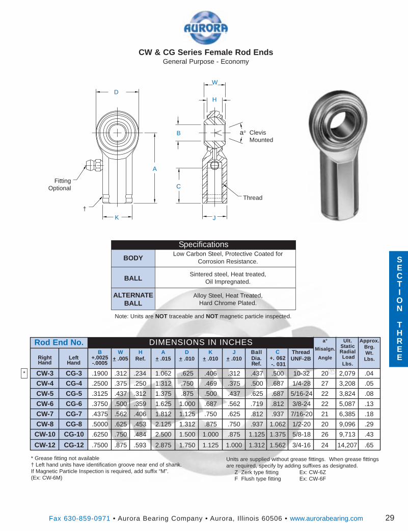
Units are supplied without grease fittings. When grease fittingsare required, specify by adding suffixes as designated.
Z Zerk type fitting Ex: CW-6ZF Flush type fitting Ex: CW-6F
Approx.Brg.Wt.Lbs.
Fax 630-859-0971 • Aurora Bearing Company • Aurora, Illinois 60506 • www.aurorabearing.com
Ult.StaticRadialLoadLbs.
ThreadUNF-2B
D+ .010
HRef.
B+.0025-.0005
CW & CG Series Female Rod EndsGeneral Purpose - Economy
D
a° ClevisMounted
W
A
B
H
CFitting
Optional
CW-3 CG-3 .1900 .312 .234 1.062 .625 .406 .312 .437 .500 10-32 20 2,079 .04
C+. 062-. 031
BallDia.Ref.
A+ .015
DIMENSIONS IN INCHESW
+ .005RightHand
K+ .010
J+ .010
CW-4 CG-4 .2500 .375 .250 1.312 .750 .469 .375 .500 .687 1/4-28 27 3,208 .05
CW-5 CG-5 .3125 .437 .312 1.375 .875 .500 .437 .625 .687 5/16-24 22 3,824 .08
CW-6 CG-6 .3750 .500 .359 1.625 1.000 .687 .562 .719 .812 3/8-24 22 5,087 .13
CW-7 CG-7 .4375 .562 .406 1.812 1.125 .750 .625 .812 .937 7/16-20 21 6,385 .18
CW-8 CG-8 .5000 .625 .453 2.125 1.312 .875 .750 .937 1.062 1/2-20 20 9,096 .29
CW-10 CG-10 .6250 .750 .484 2.500 1.500 1.000 .875 1.125 1.375 5/8-18 26 9,713 .43
LeftHand
JK
* Grease fitting not available† Left hand units have identification groove near end of shank.If Magnetic Particle Inspection is required, add suffix “M”.(Ex: CW-6M)
Rod End No. a°
Misalgn.
Angle
CW-12 CG-12 .7500 .875 .593 2.875 1.750 1.125 1.000 1.312 1.562 3/4-16 24 14,207 .65
29
†
Thread
BODY
BALL
ALTERNATEBALL
Note: Units are NOT traceable and NOT magnetic particle inspected.
SpecificationsLow Carbon Steel, Protective Coated for
Corrosion Resistance.
Sintered steel, Heat treated,Oil Impregnated.
Alloy Steel, Heat Treated,Hard Chrome Plated.
*
SECTION
THREE
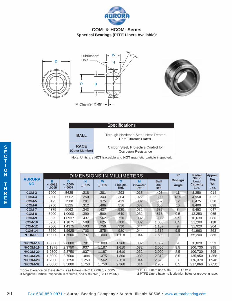
COM- & HCOM- SeriesSpherical Bearings (PTFE Liners Available) 1
D
a°W
O B
H
Lubrication2
Hole
M Chamfer X 45°
* Bore tolerance on these items is as follows - INCH: +.0025, - .0005.If Magnetic Particle Inspection is required, add suffix “M” (Ex: COM-6M)
Fax 630-859-0971 • Aurora Bearing Company • Aurora, Illinois 60506 • www.aurorabearing.com30
a°
Misalign.
AngleO
Flat DiaRef.
BallDia.Ref.
D+ .0000- .0007
MChamfer
Ref.
H+ .005
W+ .005
AURORANO.
COM-3 .1900 .5625 .218 .281 .293 .015 .406 11 3,250 .014COM-4 .2500 .6562 .250 .343 .364 .022 .500 13.5 4,950 .022COM-5 .3125 .7500 .281 .375 .419 .032 .562 12 6,475 .030COM-6 .3750 .8125 .312 .406 .516 .032 .656 10 8,400 .038COM-7 .4375 .9062 .343 .437 .530 .032 .687 8 9,453 .047COM-8 .5000 1.0000 .390 .500 .640 .032 .813 9.5 13,250 .065COM-9 .5625 1.0937 .437 .562 .710 .032 .906 9.5 16,630 .086
COM-10 .6250 1.1875 .500 .625 .780 .032 1.000 8.5 21,280 .110COM-12 .7500 1.4375 .593 .750 .920 .044 1.187 9 31,920 .204COM-14 .8750 1.5625 .703 .875 .980 .044 1.312 9.5 41,960 .263*COM-16 1.0000 1.7500 .797 1.000 1.118 .044 1.500 10 55,200 .386
*HCOM-16 1.0000 2.0000 .781 1.000 1.360 .032 1.687 9 70,820 .553*HCOM-19 1.1875 2.3750 .937 1.187 1.610 .032 2.000 8.5 100,730 .895*HCOM-20 1.2500 2.3750 .937 1.187 1.610 .032 2.000 8.5 100,730 .895*HCOM-24 1.5000 2.7500 1.094 1.375 1.860 .032 2.312 8.5 135,950 1.358*HCOM-28 1.7500 3.1250 1.250 1.562 2.110 .044 2.625 8 176,370 1.948*HCOM-32 2.0000 3.5000 1.750 1.750 2.360 .044 2.937 8.5 217,060 2.650
B+ .0015- .0005
RadialStaticLoad
CapacityLbs.
Approx.Brg.Wt.Lbs.
DIMENSIONS IN MILLIMETERS
1 PTFE Liners use suffix T- Ex: COM-8T2 PTFE Liners have no lubrication holes or groove in race.
BALL
RACE(Outer Member)
Specifications
Through Hardened Steel, Heat TreatedHard Chrome Plated.
Carbon Steel, Protective Coated forCorrosion Resistance
SECTION
THREE
Note: Units are NOT traceable and NOT magnetic particle inspected.
SECTION
THREE
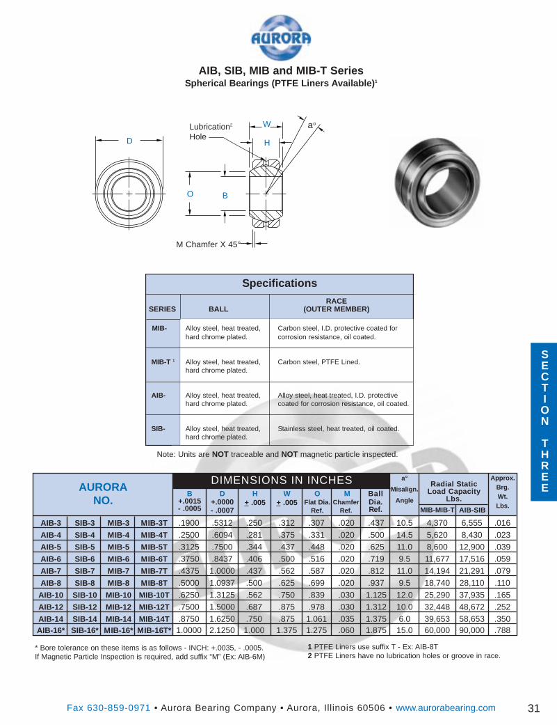
D
a°W
O B
H
Lubrication2
Hole
M Chamfer X 45°
Fax 630-859-0971 • Aurora Bearing Company • Aurora, Illinois 60506 • www.aurorabearing.com
AIB, SIB, MIB and MIB-T SeriesSpherical Bearings (PTFE Liners Available) 1
31
Approx.Brg.Wt.Lbs.
Radial StaticLoad Capacity
Lbs.D
+.0000- .0007
H+ .005
B+.0015- .0005
MChamfer
Ref.
BallDia.Ref.
W+ .005
DIMENSIONS IN INCHESO
Flat Dia.Ref.
AURORANO.
a°
Misalign.
Angle
MIB-MIB-T AIB-SIB
AIB-3 SIB-3 MIB-3 MIB-3T .1900 .5312 .250 .312 .307 .020 .437 10.5 4,370 6,555 .016AIB-4 SIB-4 MIB-4 MIB-4T .2500 .6094 .281 .375 .331 .020 .500 14.5 5,620 8,430 .023AIB-5 SIB-5 MIB-5 MIB-5T .3125 .7500 .344 .437 .448 .020 .625 11.0 8,600 12,900 .039AIB-6 SIB-6 MIB-6 MIB-6T .3750 .8437 .406 .500 .516 .020 .719 9.5 11,677 17,516 .059AIB-7 SIB-7 MIB-7 MIB-7T .4375 1.0000 .437 .562 .587 .020 .812 11.0 14,194 21,291 .079AIB-8 SIB-8 MIB-8 MIB-8T .5000 1.0937 .500 .625 .699 .020 .937 9.5 18,740 28,110 .110
AIB-10 SIB-10 MIB-10 MIB-10T .6250 1.3125 .562 .750 .839 .030 1.125 12.0 25,290 37,935 .165AIB-12 SIB-12 MIB-12 MIB-12T .7500 1.5000 .687 .875 .978 .030 1.312 10.0 32,448 48,672 .252AIB-14 SIB-14 MIB-14 MIB-14T .8750 1.6250 .750 .875 1.061 .035 1.375 6.0 39,653 58,653 .350AIB-16* SIB-16* MIB-16* MIB-16T* 1.0000 2.1250 1.000 1.375 1.275 .060 1.875 15.0 60,000 90,000 .788
1 PTFE Liners use suffix T - Ex: AIB-8T2 PTFE Liners have no lubrication holes or groove in race.
* Bore tolerance on these items is as follows - INCH: +.0035, - .0005.If Magnetic Particle Inspection is required, add suffix “M” (Ex: AIB-6M)
Note: Units are NOT traceable and NOT magnetic particle inspected.
SECTION
THREE
Specifications
RACESERIES BALL (OUTER MEMBER)
MIB- Alloy steel, heat treated, Carbon steel, I.D. protective coated forhard chrome plated. corrosion resistance, oil coated.
MIB-T 1 Alloy steel, heat treated, Carbon steel, PTFE Lined.hard chrome plated.
AIB- Alloy steel, heat treated, Alloy steel, heat treated, I.D. protectivehard chrome plated. coated for corrosion resistance, oil coated.
SIB- Alloy steel, heat treated, Stainless steel, heat treated, oil coated.hard chrome plated.
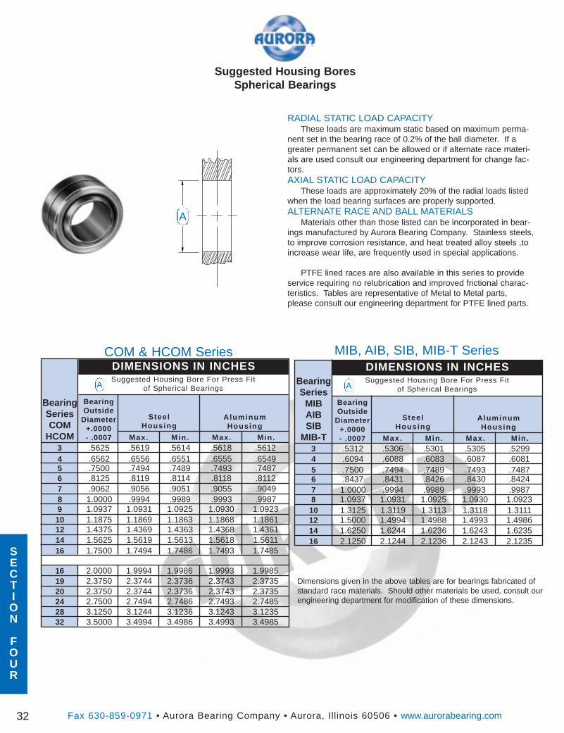
SECTION
FOUR
Suggested Housing BoresSpherical Bearings
Fax 630-859-0971 • Aurora Bearing Company • Aurora, Illinois 60506 • www.aurorabearing.com32
Min.Max. Min. Max.
BearingSeriesCOM
HCOM3 .5625 .5619 .5614 .5618 .56124 .6562 .6556 .6551 .6555 .65495 .7500 .7494 .7489 .7493 .74876 .8125 .8119 .8114 .8118 .81127 .9062 .9056 .9051 .9055 .90498 1.0000 .9994 .9989 .9993 .99879 1.0937 1.0931 1.0925 1.0930 1.0923
10 1.1875 1.1869 1.1863 1.1868 1.186112 1.4375 1.4369 1.4363 1.4368 1.436114 1.5625 1.5619 1.5613 1.5618 1.561116 1.7500 1.7494 1.7486 1.7493 1.7485
16 2.0000 1.9994 1.9986 1.9993 1.998519 2.3750 2.3744 2.3736 2.3743 2.373520 2.3750 2.3744 2.3736 2.3743 2.373524 2.7500 2.7494 2.7486 2.7493 2.748528 3.1250 3.1244 3.1236 3.1243 3.123532 3.5000 3.4994 3.4986 3.4993 3.4985
BearingOutside
Diameter+.0000- .0007
DIMENSIONS IN INCHESSuggested Housing Bore For Press Fit
of Spherical Bearings
SteelHousing
AluminumHousing
COM & HCOM Series
Dimensions given in the above tables are for bearings fabricated ofstandard race materials. Should other materials be used, consult ourengineering department for modification of these dimensions.
Min.Max. Min. Max.
BearingSeries
MIBAIBSIB
MIB-T3 .5312 .5306 .5301 .5305 .52994 .6094 .6088 .6083 .6087 .60815 .7500 .7494 .7489 .7493 .74876 .8437 .8431 .8426 .8430 .84247 1.0000 .9994 .9989 .9993 .99878 1.0937 1.0931 1.0925 1.0930 1.092310 1.3125 1.3119 1.3113 1.3118 1.311112 1.5000 1.4994 1.4988 1.4993 1.498614 1.6250 1.6244 1.6236 1.6243 1.623516 2.1250 2.1244 2.1236 2.1243 2.1235
BearingOutside
Diameter+.0000- .0007
DIMENSIONS IN INCHESSuggested Housing Bore For Press Fit
of Spherical Bearings
SteelHousing
AluminumHousing
RADIAL STATIC LOAD CAPACITYThese loads are maximum static based on maximum perma-
nent set in the bearing race of 0.2% of the ball diameter. If agreater permanent set can be allowed or if alternate race materi-als are used consult our engineering department for change fac-tors.AXIAL STATIC LOAD CAPACITY
These loads are approximately 20% of the radial loads listedwhen the load bearing surfaces are properly supported.ALTERNATE RACE AND BALL MATERIALS
Materials other than those listed can be incorporated in bear-ings manufactured by Aurora Bearing Company. Stainless steels,to improve corrosion resistance, and heat treated alloy steels ,toincrease wear life, are frequently used in special applications.
PTFE lined races are also available in this series to provideservice requiring no relubrication and improved frictional charac-teristics. Tables are representative of Metal to Metal parts,please consult our engineering department for PTFE lined parts.
MIB, AIB, SIB, MIB-T Series
A
A A
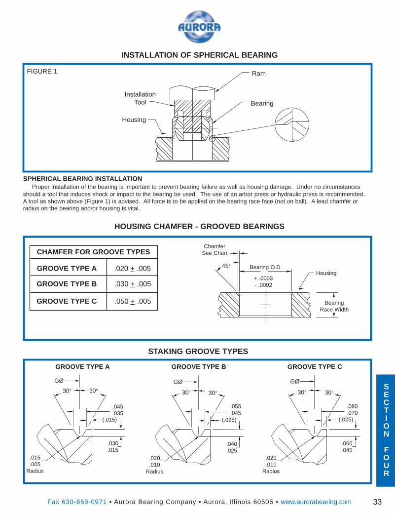
Fax 630-859-0971 • Aurora Bearing Company • Aurora, Illinois 60506 • www.aurorabearing.com 33
Ram
BearingInstallation
Tool
Housing
FIGURE 1
INSTALLATION OF SPHERICAL BEARING
SPHERICAL BEARING INSTALLATIONProper installation of the bearing is important to prevent bearing failure as well as housing damage. Under no circumstances
should a tool that induces shock or impact to the bearing be used. The use of an arbor press or hydraulic press is recommended.A tool as shown above (Figure 1) is advised. All force is to be applied on the bearing race face (not on ball). A lead chamfer orradius on the bearing and/or housing is vital.
HOUSING CHAMFER - GROOVED BEARINGS
STAKING GROOVE TYPES
45°
+ .0003- .0002
Housing
BearingRace Width
Bearing O.D.
ChamferSee Chart
GROOVE TYPE A .020 + .005
GROOVE TYPE B .030 + .005
GROOVE TYPE C .050 + .005
30° 30° 30°30° 30°30°
.045
.035(.015)
.030
.015
.055
.045
.040
.025.015.005
Radius
.060
.045
.080
.070
.020
.010Radius
.020
.010Radius
GROOVE TYPE A GROOVE TYPE B GROOVE TYPE C
(.025) (.025)
GØ GØ GØSECTION
FOUR
CHAMFER FOR GROOVE TYPES
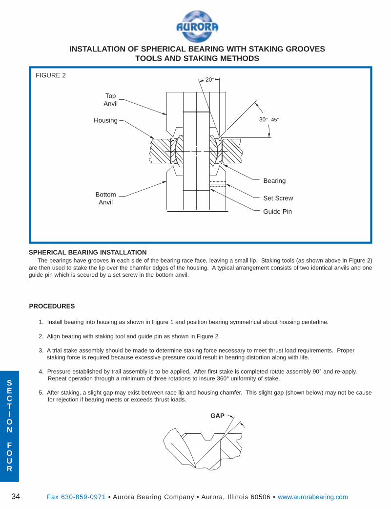
Fax 630-859-0971 • Aurora Bearing Company • Aurora, Illinois 60506 • www.aurorabearing.com34
Set Screw
Bearing
TopAnvil
Housing
FIGURE 2
INSTALLATION OF SPHERICAL BEARING WITH STAKING GROOVESTOOLS AND STAKING METHODS
20°
Guide Pin
BottomAnvil
30°- 45°
SPHERICAL BEARING INSTALLATIONThe bearings have grooves in each side of the bearing race face, leaving a small lip. Staking tools (as shown above in Figure 2)
are then used to stake the lip over the chamfer edges of the housing. A typical arrangement consists of two identical anvils and oneguide pin which is secured by a set screw in the bottom anvil.
PROCEDURES
1. Install bearing into housing as shown in Figure 1 and position bearing symmetrical about housing centerline.
2. Align bearing with staking tool and guide pin as shown in Figure 2.
3. A trial stake assembly should be made to determine staking force necessary to meet thrust load requirements. Properstaking force is required because excessive pressure could result in bearing distortion along with life.
4. Pressure established by trail assembly is to be applied. After first stake is completed rotate assembly 90° and re-apply.Repeat operation through a minimum of three rotations to insure 360° uniformity of stake.
5. After staking, a slight gap may exist between race lip and housing chamfer. This slight gap (shown below) may not be causefor rejection if bearing meets or exceeds thrust loads.
GAP
SECTION
FOUR
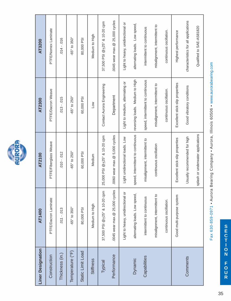
Line
rD
esig
natio
nAT
1400
AT21
00AT
2300
AT32
00
Con
stru
ctio
nP
TF
E/D
acro
nLa
min
ate
PT
FE
/Fib
ergl
ass
Wea
veP
TF
E/D
acro
nW
eave
PT
FE
/Nom
exLa
min
ate
Thi
ckne
ss(in
.).0
11-
.013
.010
-.0
12.0
13-
.015
.014
-.0
16
Tem
pera
ture
(°F
)-6
5°to
350°
-65°
to25
0°-6
5°to
250°
-65°
to35
0°
Sta
ticLi
mit
Load
80,0
00P
SI
60,0
00P
SI
60,0
00P
SI
80,0
00P
SI
Stif
fnes
sM
ediu
mto
Hig
hM
ediu
mLo
wM
ediu
mto
Hig
h
Typi
cal
37,5
00P
SI
@+
25°
&10
-20
cpm
25,0
00P
SI
@+
25°
&10
-20
cpm
Con
tact
Aur
ora
Eng
inee
ring
37,5
00P
SI
@+
25°
&10
-20
cpm
Per
form
ance
.004
5w
ear
max
.@25
,000
cycl
es.0
060
wea
rm
ax.@
5,00
0cy
cles
Dep
artm
ent
.004
5w
ear
max
.@25
,000
cycl
es
Ligh
tto
heav
y,un
idire
ctio
nalo
rLi
ght
unid
irect
iona
lloa
ds.
Low
Ligh
tto
med
ium
,al
tern
atin
gor
Ligh
tto
heav
y,un
idire
ctio
nalo
r
Dyn
amic
alte
rnat
ing
load
s.Lo
wsp
eed,
spee
d,in
term
itten
tto
cont
inuo
usre
vers
ing
load
s.M
ediu
mto
Hig
hal
tern
atin
glo
ads.
Low
spee
d,
Cap
abili
ties
inte
rmitt
ent
toco
ntin
uous
mis
alig
nmen
t,in
term
itten
tto
spee
d,in
term
itten
tto
cont
inuo
usin
term
itten
tto
cont
inuo
us
mis
alig
nmen
t,in
term
itten
tto
cont
inuo
usos
cilla
tion
mis
alig
nmen
t,in
term
itten
tto
mis
alig
nmen
t,in
term
itten
tto
cont
inuo
usos
cilla
tion.
cont
inuo
usos
cilla
tion.
cont
inuo
usos
cilla
tion.
Goo
dm
ulti-
purp
ose
syst
emE
xcel
lent
stic
k-sl
ippr
oper
ties
Exc
elle
ntst
ick-
slip
prop
ertie
sH
ighe
stpe
rfor
man
ce
Com
men
tsU
sual
lyre
com
men
ded
for
high
Goo
dvi
brat
ory
cond
ition
sch
arac
teris
tics
for
alla
pplic
atio
ns
spla
shor
unde
rwat
erap
plic
atio
nsQ
ualif
ied
toS
AE
-AS
8182
0
Fa
x6
30
-85
9-0
97
1•
Au
rora
Be
ari
ng
Co
mp
an
y•
Au
rora
,Il
lino
is6
05
06
•w
ww
.aur
orab
earin
g.co
m
35
SECTION
FOUR
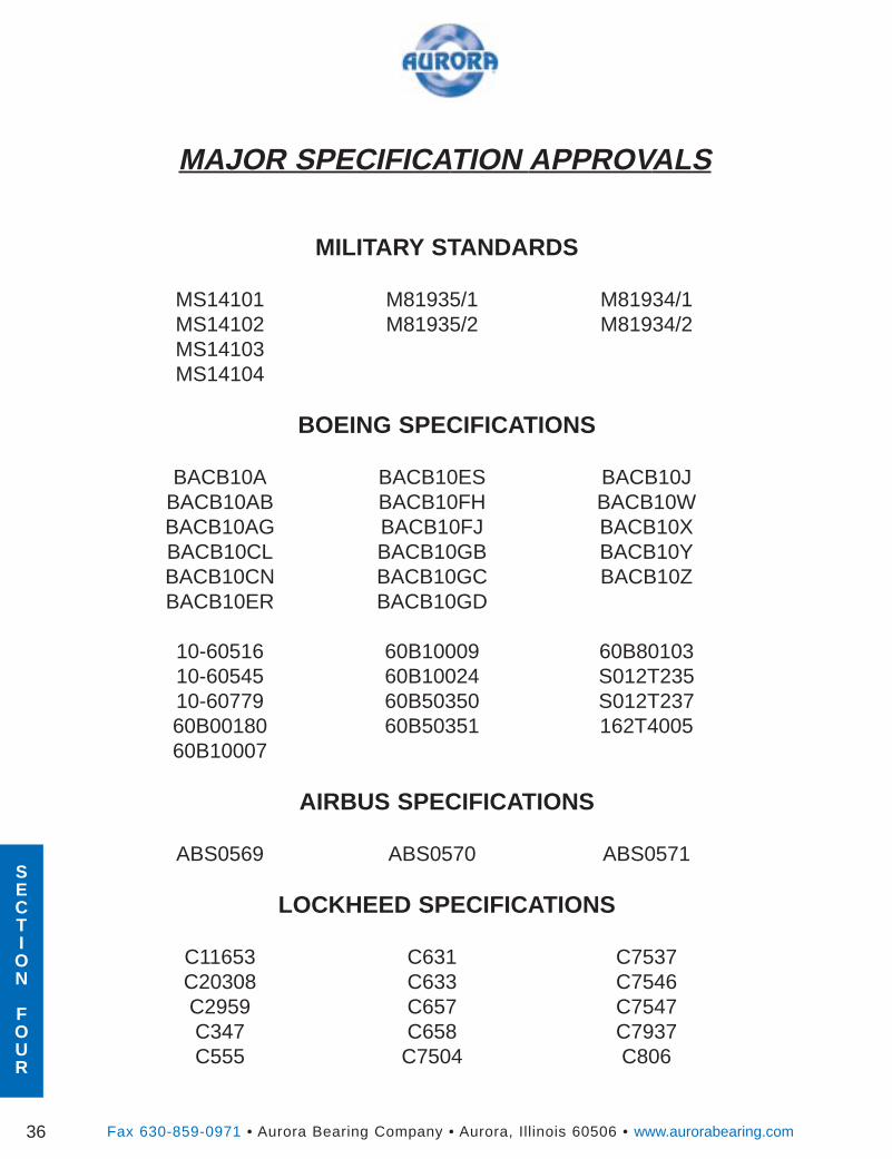
SECTION
FOUR
Fax 630-859-0971 • Aurora Bearing Company • Aurora, Illinois 60506 • www.aurorabearing.com36
MAJOR SPECIFICATION APPROVALS
MILITARY STANDARDS
MS14101 M81935/1 M81934/1MS14102 M81935/2 M81934/2MS14103MS14104
BOEING SPECIFICATIONS
BACB10A BACB10ES BACB10JBACB10AB BACB10FH BACB10WBACB10AG BACB10FJ BACB10XBACB10CL BACB10GB BACB10YBACB10CN BACB10GC BACB10ZBACB10ER BACB10GD
10-60516 60B10009 60B8010310-60545 60B10024 S012T23510-60779 60B50350 S012T23760B00180 60B50351 162T400560B10007
AIRBUS SPECIFICATIONS
ABS0569 ABS0570 ABS0571
LOCKHEED SPECIFICATIONS
C11653 C631 C7537C20308 C633 C7546C2959 C657 C7547C347 C658 C7937C555 C7504 C806
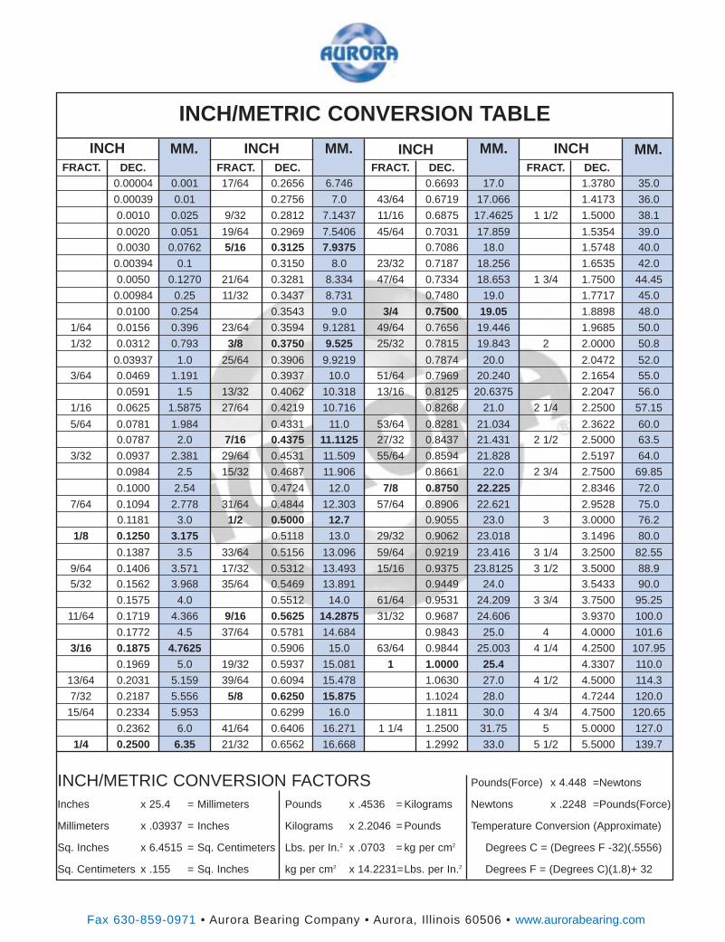
Fax 630-859-0971 • Aurora Bearing Company • Aurora, Illinois 60506 • www.aurorabearing.com
0.00004 0.001 17/64 0.2656 6.746 0.6693 17.0 1.3780 35.0
0.00039 0.01 0.2756 7.0 43/64 0.6719 17.066 1.4173 36.0
0.0010 0.025 9/32 0.2812 7.1437 11/16 0.6875 17.4625 1 1/2 1.5000 38.1
0.0020 0.051 19/64 0.2969 7.5406 45/64 0.7031 17.859 1.5354 39.00.0030 0.0762 5/16 0.3125 7.9375 0.7086 18.0 1.5748 40.0
0.00394 0.1 0.3150 8.0 23/32 0.7187 18.256 1.6535 42.0
0.0050 0.1270 21/64 0.3281 8.334 47/64 0.7334 18.653 1 3/4 1.7500 44.45
0.00984 0.25 11/32 0.3437 8.731 0.7480 19.0 1.7717 45.0
0.0100 0.254 0.3543 9.0 3/4 0.7500 19.05 1.8898 48.0
1/64 0.0156 0.396 23/64 0.3594 9.1281 49/64 0.7656 19.446 1.9685 50.0
1/32 0.0312 0.793 3/8 0.3750 9.525 25/32 0.7815 19.843 2 2.0000 50.8
0.03937 1.0 25/64 0.3906 9.9219 0.7874 20.0 2.0472 52.03/64 0.0469 1.191 0.3937 10.0 51/64 0.7969 20.240 2.1654 55.0
0.0591 1.5 13/32 0.4062 10.318 13/16 0.8125 20.6375 2.2047 56.0
1/16 0.0625 1.5875 27/64 0.4219 10.716 0.8268 21.0 2 1/4 2.2500 57.15
5/64 0.0781 1.984 0.4331 11.0 53/64 0.8281 21.034 2.3622 60.00.0787 2.0 7/16 0.4375 11.1125 27/32 0.8437 21.431 2 1/2 2.5000 63.5
3/32 0.0937 2.381 29/64 0.4531 11.509 55/64 0.8594 21.828 2.5197 64.0
0.0984 2.5 15/32 0.4687 11.906 0.8661 22.0 2 3/4 2.7500 69.85
0.1000 2.54 0.4724 12.0 7/8 0.8750 22.225 2.8346 72.0
7/64 0.1094 2.778 31/64 0.4844 12.303 57/64 0.8906 22.621 2.9528 75.0
0.1181 3.0 1/2 0.5000 12.7 0.9055 23.0 3 3.0000 76.2
1/8 0.1250 3.175 0.5118 13.0 29/32 0.9062 23.018 3.1496 80.0
0.1387 3.5 33/64 0.5156 13.096 59/64 0.9219 23.416 3 1/4 3.2500 82.55
9/64 0.1406 3.571 17/32 0.5312 13.493 15/16 0.9375 23.8125 3 1/2 3.5000 88.95/32 0.1562 3.968 35/64 0.5469 13.891 0.9449 24.0 3.5433 90.0
0.1575 4.0 0.5512 14.0 61/64 0.9531 24.209 3 3/4 3.7500 95.25
11/64 0.1719 4.366 9/16 0.5625 14.2875 31/32 0.9687 24.606 3.9370 100.0
0.1772 4.5 37/64 0.5781 14.684 0.9843 25.0 4 4.0000 101.6
3/16 0.1875 4.7625 0.5906 15.0 63/64 0.9844 25.003 4 1/4 4.2500 107.95
0.1969 5.0 19/32 0.5937 15.081 1 1.0000 25.4 4.3307 110.0
13/64 0.2031 5.159 39/64 0.6094 15.478 1.0630 27.0 4 1/2 4.5000 114.3
7/32 0.2187 5.556 5/8 0.6250 15.875 1.1024 28.0 4.7244 120.0
15/64 0.2334 5.953 0.6299 16.0 1.1811 30.0 4 3/4 4.7500 120.65
0.2362 6.0 41/64 0.6406 16.271 1 1/4 1.2500 31.75 5 5.0000 127.0
1/4 0.2500 6.35 21/32 0.6562 16.668 1.2992 33.0 5 1/2 5.5000 139.7
FRACT. DEC. FRACT. DEC. FRACT. DEC. FRACT. DEC.
INCH INCH INCH INCHMM. MM. MM. MM.
INCH/METRIC CONVERSION FACTORS Pounds(Force) x 4.448 =Newtons
Inches x 25.4 = Millimeters Pounds x .4536 = Kilograms Newtons x .2248 =Pounds(Force)
Millimeters x .03937 = Inches Kilograms x 2.2046 = Pounds Temperature Conversion (Approximate)
Sq. Inches x 6.4515 = Sq. Centimeters Lbs. per In.2 x .0703 = kg per cm2 Degrees C = (Degrees F -32)(.5556)
Sq. Centimeters x .155 = Sq. Inches kg per cm2 x 14.2231=Lbs. per In.2 Degrees F = (Degrees C)(1.8)+ 32
INCH/METRIC CONVERSION TABLE
Aurora Bearing Co.970 South Lake St.Aurora, IL 60506U.S.A.
PHONE: (630) 859-2030FAX: (630) 859-0971www.aurorabearing.com
e-mail: [email protected]
SPECIALLY DESIGNED
ROD ENDS, BEARINGS & BUSHINGSTo meet the requirements of airframe manufacturers.
Let us design specials to meet your specific applications.
Recommended