Audi 80, Audi 90 Current Flow Diagram No.9
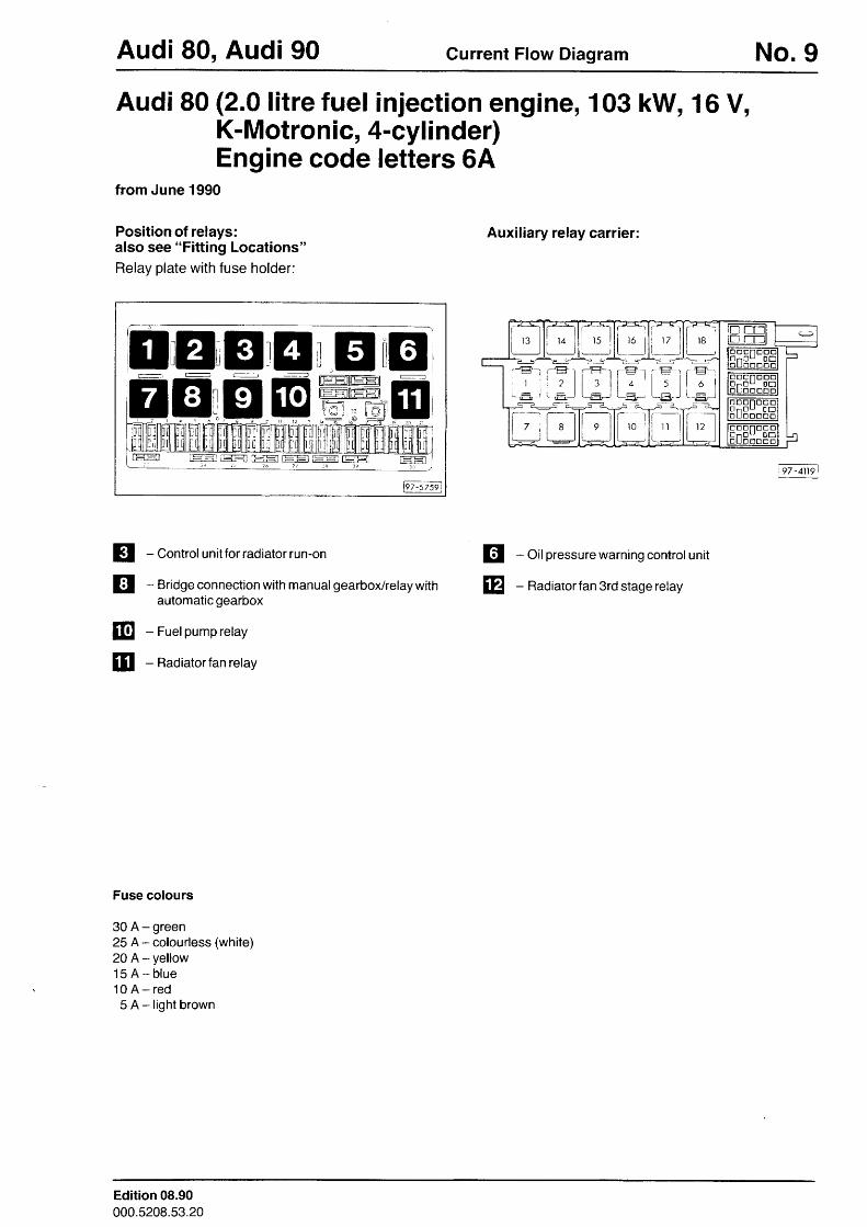
Audi 80 (2.0 litre fuel injection engine, 103 kW, 16 V,K-Motron ic, 4-cyl i nder)Engine code letters 6A
from June 1990
Position of relays:also see "Fitting Locations"Relay plate with fuse holder:
Auxiliary relay carrier:
Ft-szsil
tr@
- Oil pressure warning control unit
- Radiatorfan 3rd stage relay
IuI[
iT-- 'r
l l rBi l lL=--=-. E *
t - jt 6 lL.E -i
[i- --ri 1 2 l
i - - - - . "1i 1 7
r___l
i ;l ) lL-EL-J
L-_l
l--ti i l |
' 1 5 |
/__JE-_
| : Il J lI I
\rElrJ
t t 6 lt ll. -l
l - ll 4-ry
q - ;
-- --rl l 0 rI
; l i t I' l : : IiEl- 'rEl--
- l_ l+
l- --]
[-_l| 7 ; l 8 |+i L:l
!l - Conrrol unitforraotatorrun-on
tr - Bridgeconnectionwith manual gearbox/relaywithautomatic gearbox
- Fuelpump relay
- Radiatorfan relay
Fuse colours
30 A - green25 A- colourless (white)20 A- yel low15 A - b lue1 0 A - r e d5 A - l i g h t b r o w n
Edition 08.90000.5208.53.20
No.9l1 Gurrent Flow Diagram Audi 80, Audi 90
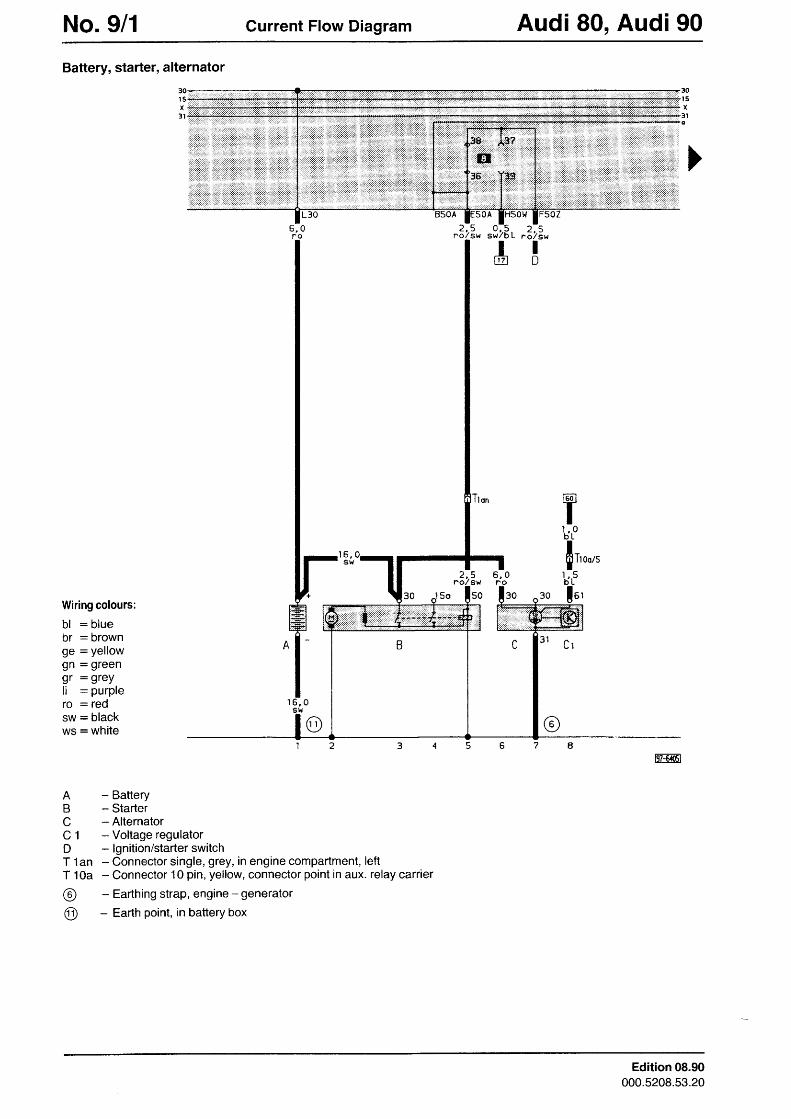
Battery, starter, alternator
30r sx
3 lo
30
x3 l
FSOZ
5sl{
w
nL2, .o/
ID
r l qsl76
IUZ]
) qn o l s h ,
z - l 6 , 0sr{ n
30Wiring colours:
bl : bluebr : brownge = yellowgn = greengr : grey;1 : purplero : redsw = blackws = white
o
o
- Battery- Starter- Alternator- Voltage regulator- lgnition/starter switch* Connector single, grey, in engine compartment, left- Connector 10 pin, yellow, connector point in aux. relay carrier- Eafthing strap, engine - generator- Earth point, in battery box
FFffi'I
ABcC 1DT 1 a nT 1 0 a
@@
Edition 08.90000.5208.53.20
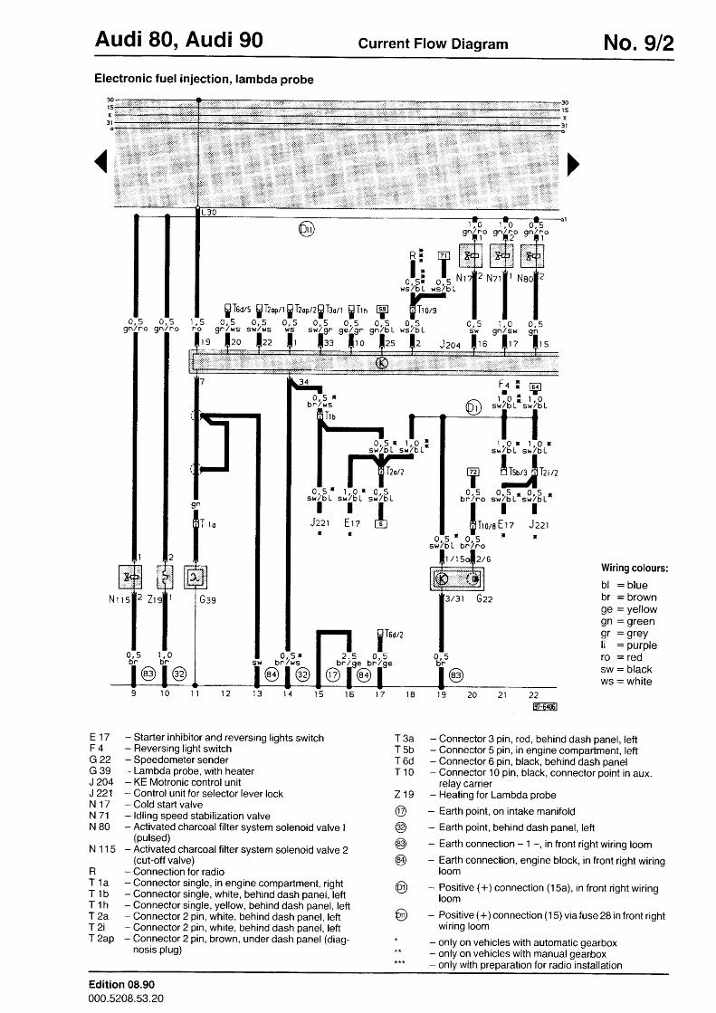
Audi 80, Audi 90 Current Flow Diagram No.9l2Electronic fuel injection, lambda probe
0 , 5n o
ffi
I'1 , 0bn
0 , 5bn
F4 I
::r.::::i:r.: i: a:: :: : : : i : i : i : : : 1 . : , : :
iii=:iiiiF
f6?-r-
swilb L0 , 5 r
bn lws e,h u
n-q r
srJ / o L
TJzzt
t
1 , , 0 rsw /b L
IEtz
ll
0 , .5 . r t , p . is b t / D L s r { / b L
IL-EJ
ITson0 , 5
bn /ge
.J,z8i "lzBi
? !in,,
I o . s rw b r l w s
@l@2
br
@
Wiring colours:
bl : bluebr = brownge = yellowgn : greengr : grey;1 = purplero = redsw : blackwS: whi te
E 17 - Starter inhibitor and reversing lights switchF 4 - Reversing light switchG 22 - Speedometer senderG 39 - Lambda probe, with heaterJ 204 - KE Motronic control unitJ 221 - Control unit for selector lever lockN 17 - Cold stad valveN 71 - ldling speed stabilization valveN 80 - Activated charcoalfilter system solenoid valve I
(pulsed)N 1 15 - Activated charcoal filter system solenoid valve 2
(cut-off valve)R - Connection for radioT 1a - Connector single, in engine compartment, rightT 1b - Connector single, white, behind dash panel, leftT t h - Connector single, yellow, behind dash panel, leftT 2a - Connector 2 pin, white, behind dash panel, leftT 2i - Connector 2 pin, white, behind dash panel, leftf 2ap - Connector 2 pin, brown, under dash panel (diag-
nosis plug)
22m6ml
T 3a - Connector 3 pin, red, behind dash panel, leftT 5b - Connector 5 pin, in engine compartment, leftT 6d - Connector 6 pin, black, behind dash panelT 10 - Connector 10 pin, black, connector point in aux.
relay carrier219 - Heating for Lambda probe
@ - Eafih point, on intake manifold
@ - Earth point, behind dash panel, left
@ - Earth connection - 1 -, in front right wiring loom
@ - Earth connection, engine block, in front right wiringloom
@ - Positive (+) connection (15a), in front right wiringloom
@ - Posit ive (+) connection (15)via fuse 28 in front r ightwiring loom
* - only on vehicles with automatic gearbox** - only on vehicles with manualgearbox*** - only with preparation for radio installation
Edition 08.90000.5208.53.20
No.913 Current Flow Diagram Audi 80, Audi 90
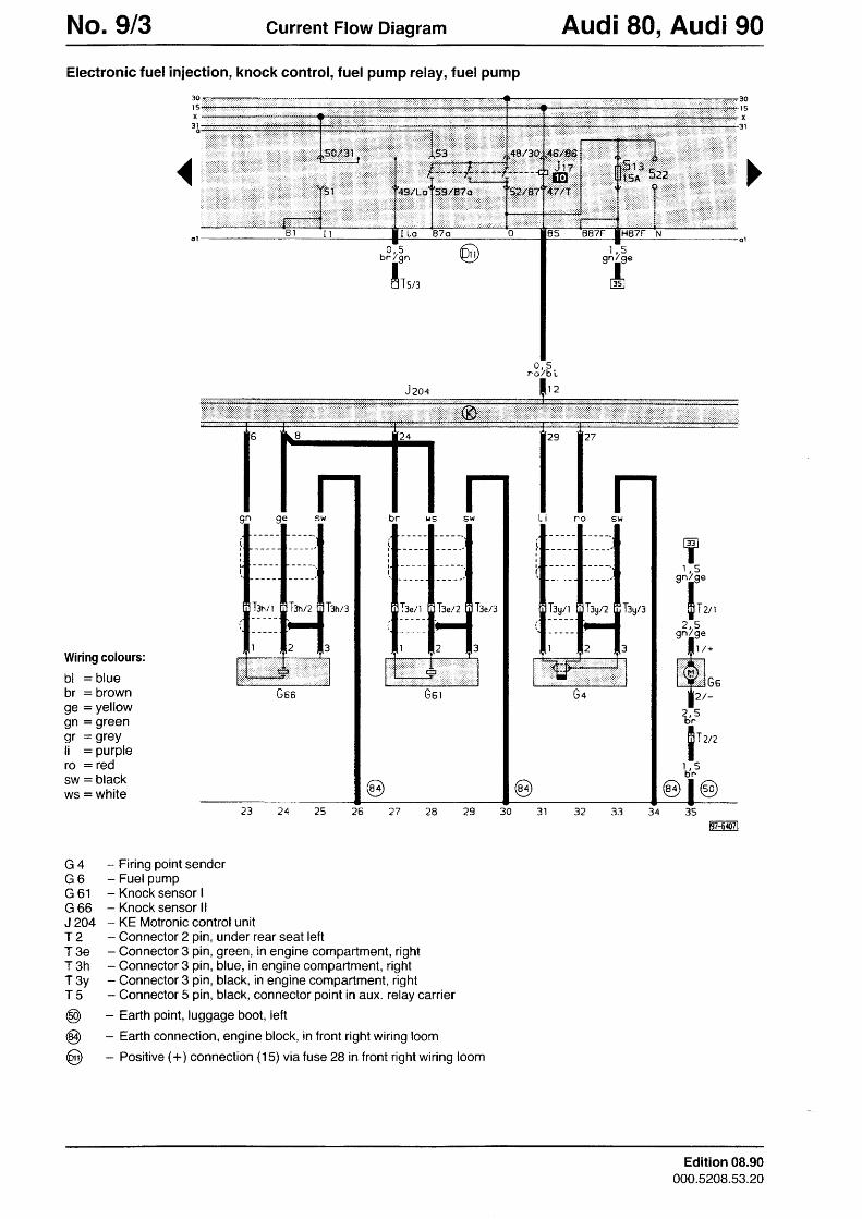
Electronic fuel injection, knock control, fuel pump relay, fuel pump
Tlen
Wiring colours:
bl : bluebr : brownge = yellowgn = greengr = grey11 : purplero : redsw: blackws = white
G 4 - Firing point senderG O - F u e l p u m pG 61 - Knocksensor IG 66 - Knock sensor l lJ 2O4 - KE Motronic control unitf 2 - Connector 2 pin, under rear seat leftT 3e - Connector 3 pin, green, in engine compartment, rightT 3h - Connector 3 pin, blue, in engine compartment, rightT 3y - Connector 3 pin, black, in engine compartment, rightT 5 - Connector 5 pin, black, connector point in aux. relay carrier
@ - Earth point, luggage boot, left
@ - Earth connection, engine block, in front right wiring loom
@ - Positive (+) connection (15) via fuse 28 in front right wiring loom
0 , 5bn /gn 9n19e
l:vrI
tJg/ t T:yn
tu]T1 q
on/oe
il,,,2,.5
qn/ qe- l\,.ffi,,
lr,-t t4T.,,,I
l . r 5br'
@l@252 423
ffi:il0-Il
Edition 08.90000.5208.53.20
Audi 80, Audi 90 Current Flow Diagram No.914
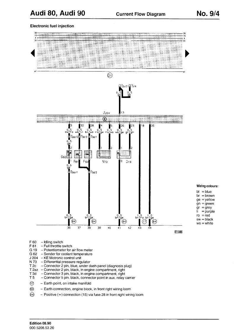
Electronic fuel injection
30l 5x
3 l
Jzoc
siTiol _O l2ozr
0 , 5
I Feri
T2oztt Iun
q e-@
Wiring colours:
bl = bluebr = brownge : yellowgn : greengr = grey;1 = purple[O = ledsw : blackws = white
5qe-@o?t
F 60 - ldling switchF 81 - Fullthrottle switchG 19 - Potentiometer for air flow meterG 62 - Sender for coolant temperatureJ 2O4 - KE Motronic control unitN 73 - Differential pressure regulatorT 2c - Connector 2 pin, blue, under dash panel (diagnosis plug)T 2az - Connector 2 pin, black, in engine compartment, rightT 3d - Connector 3 pin, black, in engine compartment, rightT 5 - Connector 5 pin, black, connector point in aux. relay carrier
@ - Earth point, on intake manifold
@ - Earth connection, engine block, in front right wiring loom
@ - Positive (+) connection (15) via fuse 28 in front right wiring loom
4 3+ z
Edition 08.90000.5208.53.20
No.9l5 Current Flow Diagram Audi 80, Audi 90
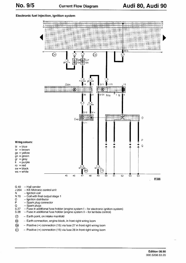
Electronic fuel injection, ignition system
3/31 Nzo
Wiring colours:
bl = bluebr : brownge : yellowgn = greengr = grey1; : purplero = redsw = blackws = white
G 40 - Hal tsenderJ 2O4 - KE-Motronic control unitN - lgnition coilN 70 - Coilwith final output stage 1O - lgnition distributorP - Spark plug connectorO - Spark plugs527 - Fuse in additional fuse holder (engine system | - for electronic ignition system)S 28 - Fuse in additional fuse holder (engine system ll - for lambda control)
@ - Earth point, on intake manifold
@ - Earth connection, engine block, in front right wiring loom
@ - Positive (+) connection (15) via fuse 27 in front right wiring loom
@ - Positive (+) connection (15) via fuse 28 in front right wiring loom
Edition 08.90000.5208.53.20
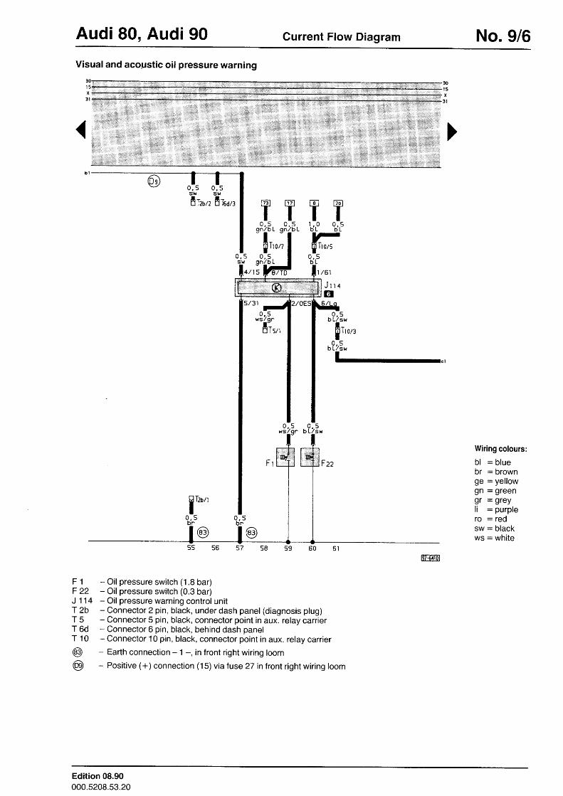
Audi 80, Audi 90 Current Flow Diagram No. 916Visual and aco_ustic oil pressure warning
F 1 - Oil pressure switch (1.8 bar)F 22 - Oil pressure switch (0.3 ba|J 114 - Oil pressure warning control unitT 2b - Connector 2 pin, black, under dash panel (diagnosis plug)T 5 - Connector 5 pin, black, connector point in aux. relay carrierT 6d - Connector 6 pin, black, behind dash panelT 10 - Connector 10 pin, black, connector point in aux. relay carrier
@ - Earth connection - 1 -, in front right wiring loom
@ - Positive (+) connection (15) via tuse 27 in front right wiring loom
0 , 5 0 , 55l.l Sr{l - l -a l2b/2 n l6d/3 [?1 |7dr
TT1 . , . 0 0 , 5b L b L
Wiring colours:
bl : b luebr = brownge : yellowgn = greengr = grey11 : purple[O : Igdsw : blackws = white
| / 6 1
3 1
Edition 08.90000.5208.53.20
No.9l7 Current Flow Diagram Audi 80, Audi 90
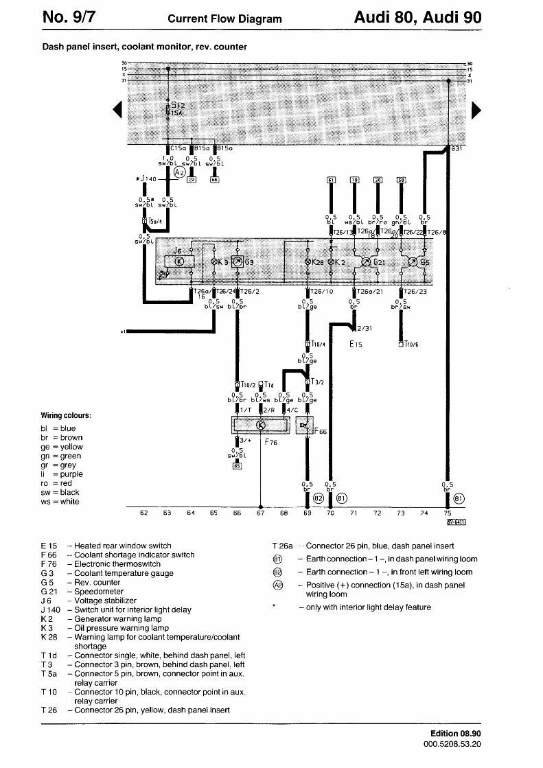
Dash panel insert, coolant monitor, rev. counter
30
Wiring colours:
bl : bluebr = brownge = yellowgn = greengr : grey11 = purplero = redsw = blackws : white
E 15 - Heated rear window switchF 66 - Coolant shortage indicator switchF 76 - Electronic thermoswitchG 3 - Coolant temperature gaugeG5 -Rev.counterG21 - SpeedometerJ6 -Vol tagestabi l izerJ 140 - Switch unit for interior light delayK2 - Generator warning lampK 3 - Oil pressure warning lampK 28 - Warning lamp for coolant temperature/coolant
shortageT 1d - Connector single, white, behind dash panel, leftT 3 - Connector 3 pin, brown, behind dash panel, leftT 5a - Connector 5 pin, brown, connector point in aux.
relay carrierT 10 - Connector 10 pin, black, connector point in aux.
relay carrierT 26 - Connector 26 pin, yellow, dash panel insert
t ) 5 l
q , sbr
T26/
75FAm
- Connector 26 pin, blue, dash panel insert- Earth connection - 1 -, in dash panelwiring loom- Earth connection - 1 -, in front left wiring loom- Positive (+) connection (15a), in dash panel
wiring loom- only with interior light delay feature
n <s w / o L
IL
T0 , 5
g^4b
T. t <
Uf
0 , 5br ' lsw
6t,0,,
lT26/0 . 5
b L,/ oe
flTroz,o?zE"
11,,,23" u?23.lo,c l"
Hffi,,
I0 , 5
h n
'2Ir260 . 5
b L/bn
Io?zE. ,
f ' r '
tffir'928..
ILell
0,,5L / S W
J/bot b
h
/2
7 4? 069675 4b 5
R
( 6
2/g
H-I
T 26a
@@@
Edition 08.90000.5208.53.20
Audi 80, Audi 90 Gurrent Flow Diagram No. 9/8
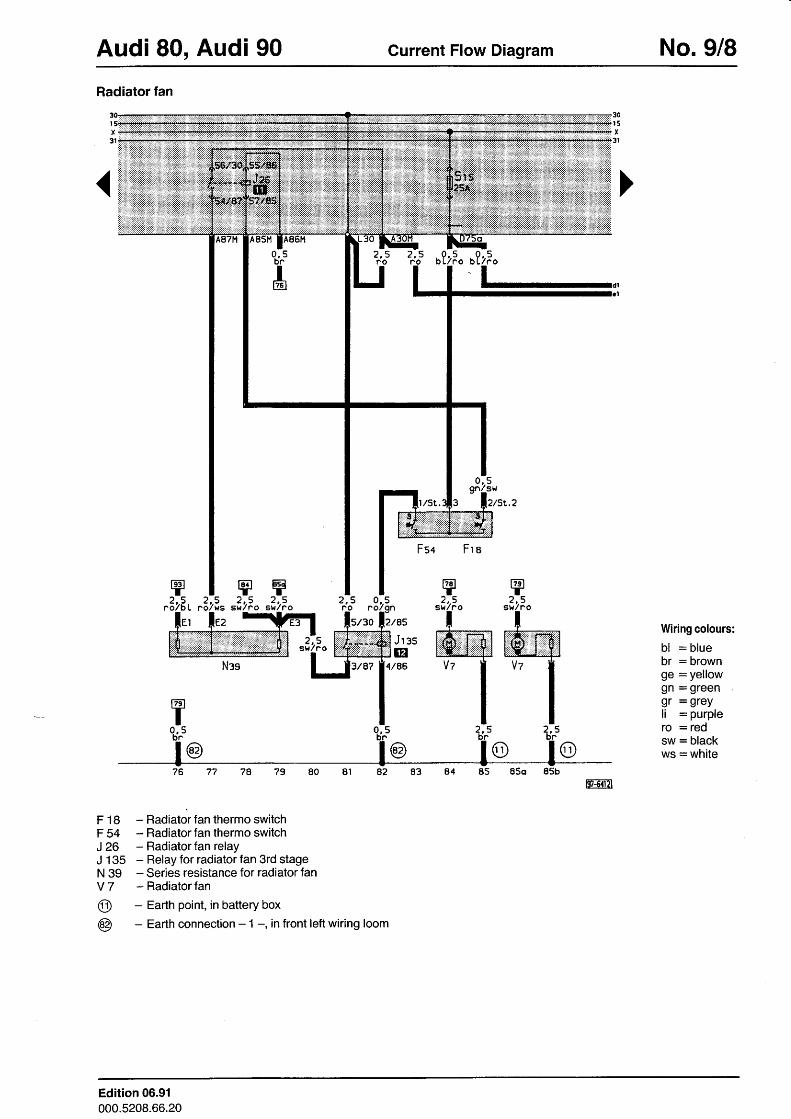
Radiator fan
fB?T2..5
sw/ no
2,.5swlno
F 18 - Radiator fan thermo switchF 54 - Radiatorfan thermo switchJ 26 - Radiator fan relayJ 135 - Relay for radiator fan 3rd stageN 39 - Series resistance for radiator fanV 7 - Radiatorfan
@ - Eadh point, in battery box
@ - Earth connection - 1 -, in front left wiring loom
2 , 5ro
'd; o?zFo o?zFo
Fsc F r a
ry2, .5
su/?o
lffivzl
ts
ry2, .5
sw/no
Jr es@
4/86
Wiring colours:
bl : bluebr = brownge = yellowgn = greengr = grey11 = purpleIO = Iedsw = blackws: whi te
FF|TZI
. 2 ,5L ro lws
Edition 06.91000.5208.66.20
No. 9/9 Gurrent Flow Diagram Audi 80, Audi 90
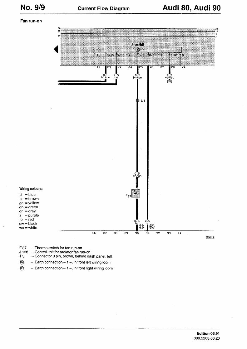
Fan run-on
K3 K2
0 , 5b L/no
Wiring colours:
bl : bluebr = brownge = yellowgn = greengr = grey;; = purplero = redsw = blackws = white
F 87 - Thermo switch for fan run-onJ 138 - Control unit for radiator fan run-onT 3 - Connector 3 pin, brown, behind dash panel, left
@ - Earth connection - 1 -, in front left wiring loom
@ - Earth connection - 1 -, in front right wiring loom
2 , 5no
I
Faz
Edition 06.91000.5208.66.20
Recommended