Model No. VLCDS24728-3W
Digital LCD Display
Service Manual
ViewSonic VP2290b-3
ViewSonic 381 Brea Canyon Road, Walnut, California 91789 USA - (800) 888-8583
(VP2290b-3_SM_891 Rev. 1a June 2004)
Copyright
Copyright 2004 by ViewSonic Corporation. All rights reserved. No part of this publication may bereproduced, transmitted, transcribed, stored in a retrieval system, or translated into any language or computer language, in any form or by any means, electronic, mechanical, magnetic, optical, chemical,manual or otherwise, without the prior written permission of ViewSonic Corporation.
Disclaimer
ViewSonic makes no representations or warranties, either expressed or implied, with respect to thecontents hereof and specifically disclaims any warranty of merchantability or fitness for any particularpurpose. Further, ViewSonic reserves the right to revise this publication and to make changes from timeto time in the contents hereof without obligation of ViewSonic to notify any person of such revision orchanges.
Trademarks
ViewSonic is a registered trademark of ViewSonic Corporation.All other trademarks used within this document are the property of their respective owners.
Optiquest is a registered trademark of ViewSonic Corporation.
Revision History
Revision Date Description Of Changes Approval
1a 06/11/04 Initial Release DCN-4529 Angela Lu
1ViewSonic Corporation Confidential - Do Not Copy VP2290b-3
Assembly (Dis-Assy) Procedure For
VIEWSONIC VP2290b MONITOR 1. Purpose
The purpose of this procedure is to ensure that all Liquid Crystal Display (LCD) repair processes adhere to the specifications set forth in Incline’s LCD Repair Process Manual, document number 11010.
2. Scope: This document delineates the generic repair processes for flat panel display. Other processes not specifically mentioned in this procedure are subject to the processes and methods delineated in the LCD Repair Process Manual 11010.
3. Responsibility: It is the responsibility of the Engineering Department to maintain this procedure.
4. Reference Documents: LCD Test Process 11010 Corrective Action Request (CAR) Form #11192 Incline LCD Traveler Form No. 11043-001
5. Tools Required: Philips screwdriver, #1 Power screwdriver (adjustable torque) Tweezers Tube tool (Hose) Cotton gloves Protective mylar film ( 12.5 ” wide ) Black ESD carrier ( 18” x 24” ) Foam cushion for carrier (approx. 12” x 20” ) Protective foam for workbench (approx. 12” x 20” ) Large ESD workstation
6. Areas Affected: Employ this procedure in all operational repair areas of Incline Corporation.
7. Document Retention Period: Retain this document for 12 months after it has been declared obsolete.
2ViewSonic Corporation Confidential - Do Not Copy VP2290b-3
Assembly (Dis-Assy) Procedure For
VIEWSONIC VP2290b MONITOR
8. STANDARDS AND PRECAUTIONS LCD panels are very delicate electronic instruments and need to be handled with great care at all times during all phases of the repair process. Below is a list of some of the DOs and DON’Ts when handling LCD panels of any kind.
8.1 ESD Before opening a LCD assembly, ensure that you are at an ESD compliant workstation with your ESD wrist strap attached. Wear gloves or finger cots to protect the LCD from fingerprints as much as possible. Keep the workstation free of debris.
8.2 Contamination/Damage Avoidance Avoid putting pressure on the plastic film covering the LCD as it can easily be damaged. Never allow the front or rear Polarizer to come into direct contact with the bench top or granite work area as this may scratch the Polarizer. Use a clean cloth to protect the surface of the LCD. Ensure that all screws are immediately placed in a container after removal from the LCD. Care should be taken with broken glass both for the safety of the operator and the LCD Polarizer. After a LCD with a broken glass panel or Backlight is discovered and processed, the workspace should be swept with a rag to remove any small bits of glass.
8.3 Product Tracking Incline has developed a custom MIS program known as FAST (Facility Automated Serial Tracking) to track and disposition all products. WIP (Work In Process) stations are located throughout the facility to allow for convenient access to FAST. Always fill out both the paper traveler and the WIP screen as accurately as possible. When moving the LCD between locations update the location on the WIP screen. Throughout this entire procedure, references are made to the LCD Matrix. The Matrix lists all of the specific tooling and setups required for each LCD. Key elements of the Matrix are also accessed through the WIP screen.
8.4 Miscellaneous
1. Always use ESD protection devices, such as a grounded workstation and wrist strap, when handling LCD panels.
2. When handling LCDs where tabs are mounted to PCBs which flex and can potentially make
contact with the polarized panel surfaces (both inside and outside polarizers) ensure that there is always a protective sheet between the PCB and the polarizer surfaces.
3. Always use an air gun to clear particles from illuminator surfaces. Never use a clean wipe.
Do not touch the illuminator surfaces with your fingers; skin oils leave a mark that is very difficult to remove without damaging the illuminator.
3ViewSonic Corporation Confidential - Do Not Copy VP2290b-3
Assembly (Dis-Assy) Procedure For
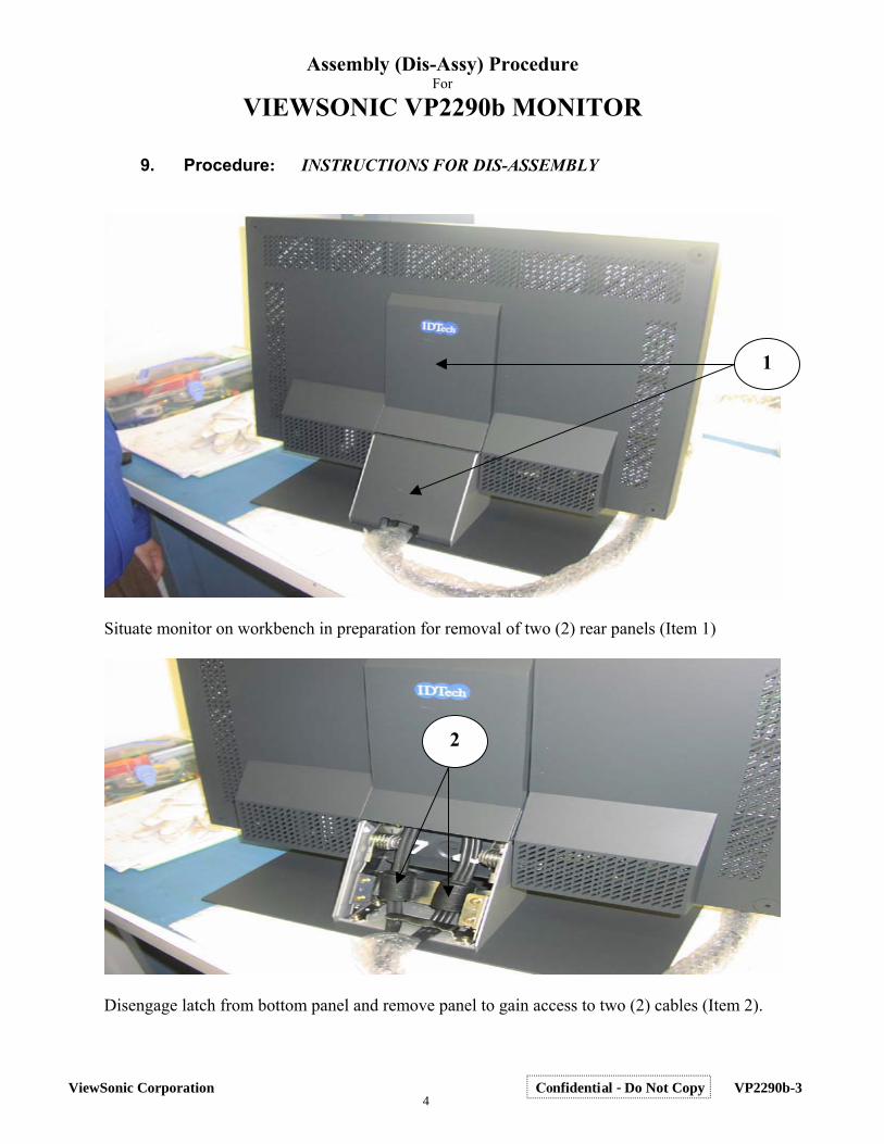
VIEWSONIC VP2290b MONITOR 9. Procedure: INSTRUCTIONS FOR DIS-ASSEMBLY
1
Situate monitor on workbench in preparation for removal of two (2) rear panels (Item 1)
2
Disengage latch from bottom panel and remove panel to gain access to two (2) cables (Item 2).
4ViewSonic Corporation Confidential - Do Not Copy VP2290b-3
Assembly (Dis-Assy) Procedure For
VIEWSONIC VP2290b MONITOR DIS-ASSEMBLY
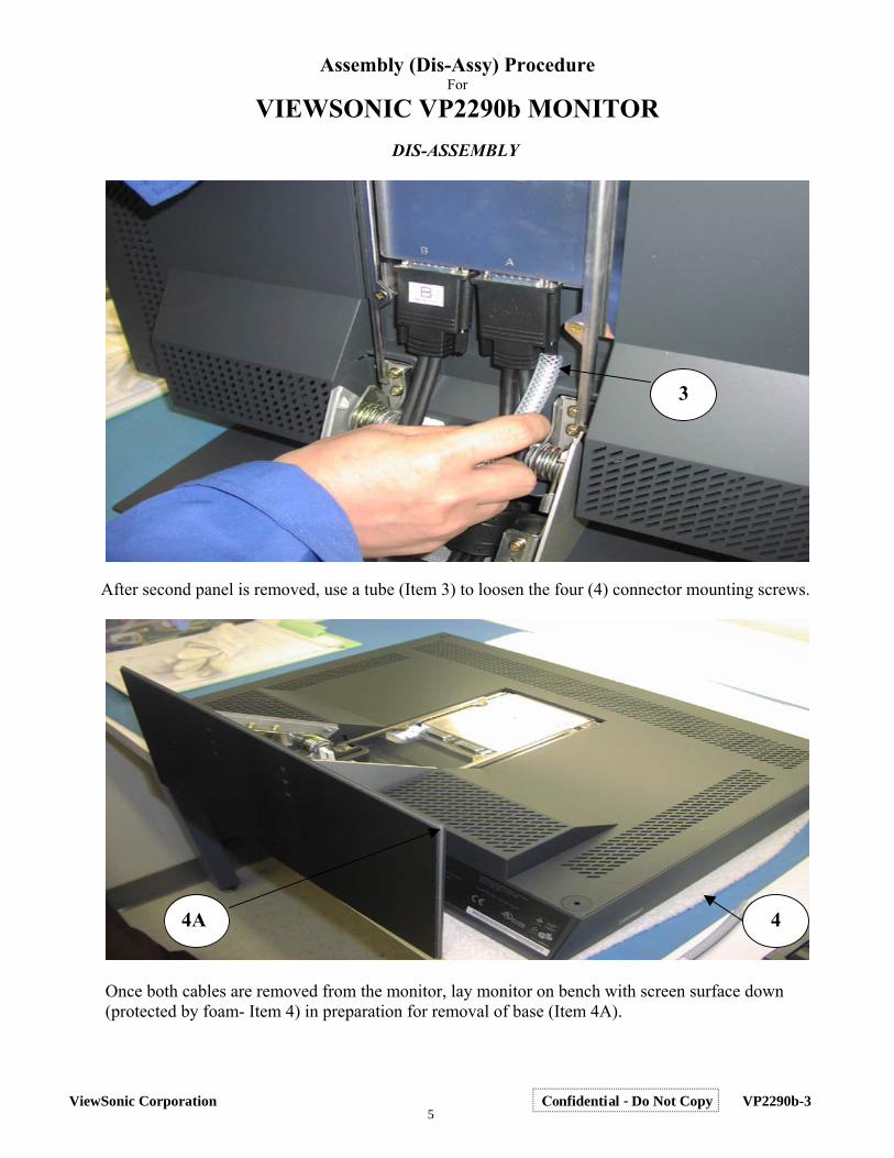
3
After second panel is removed, use a tube (Item 3) to loosen the four (4) connector mounting screws.
4A 4
Once both cables are removed from the monitor, lay monitor on bench with screen surface down
(protected by foam- Item 4) in preparation for removal of base (Item 4A).
5ViewSonic Corporation Confidential - Do Not Copy VP2290b-3
Assembly (Dis-Assy) Procedure For
VIEWSONIC VP2290b MONITOR DIS-ASSEMBLY
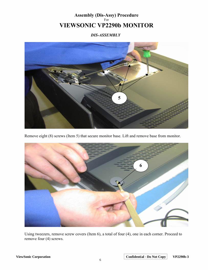
5
Remove eight (8) screws (Item 5) that secure monitor base. Lift and remove base from monitor.
6
Using tweezers, remove screw covers (Item 6), a total of four (4), one in each corner. Proceed to remove four (4) screws.
6ViewSonic Corporation Confidential - Do Not Copy VP2290b-3
Assembly (Dis-Assy) Procedure For
VIEWSONIC VP2290b MONITOR DIS-ASSEMBLY
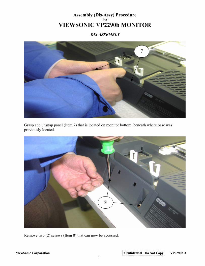
7
Grasp and unsnap panel (Item 7) that is located on monitor bottom, beneath where base was previously located.
8
Remove two (2) screws (Item 8) that can now be accessed.
7ViewSonic Corporation Confidential - Do Not Copy VP2290b-3
Assembly (Dis-Assy) Procedure For
VIEWSONIC VP2290b MONITOR DIS-ASSEMBLY
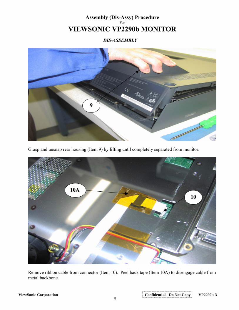
9
Grasp and unsnap rear housing (Item 9) by lifting until completely separated from monitor.
10A 10
Remove ribbon cable from connector (Item 10). Peel back tape (Item 10A) to disengage cable from metal backbone.
8ViewSonic Corporation Confidential - Do Not Copy VP2290b-3
Assembly (Dis-Assy) Procedure For
VIEWSONIC VP2290b MONITOR DIS-ASSEMBLY
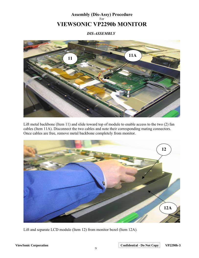
11A 11
Lift metal backbone (Item 11) and slide toward top of module to enable access to the two (2) fan cables (Item 11A). Disconnect the two cables and note their corresponding mating connectors. Once cables are free, remove metal backbone completely from monitor.
12
12A
Lift and separate LCD module (Item 12) from monitor bezel (Item 12A).
9ViewSonic Corporation Confidential - Do Not Copy VP2290b-3
Assembly (Dis-Assy) Procedure For
VIEWSONIC VP2290b MONITOR DIS-ASSEMBLY
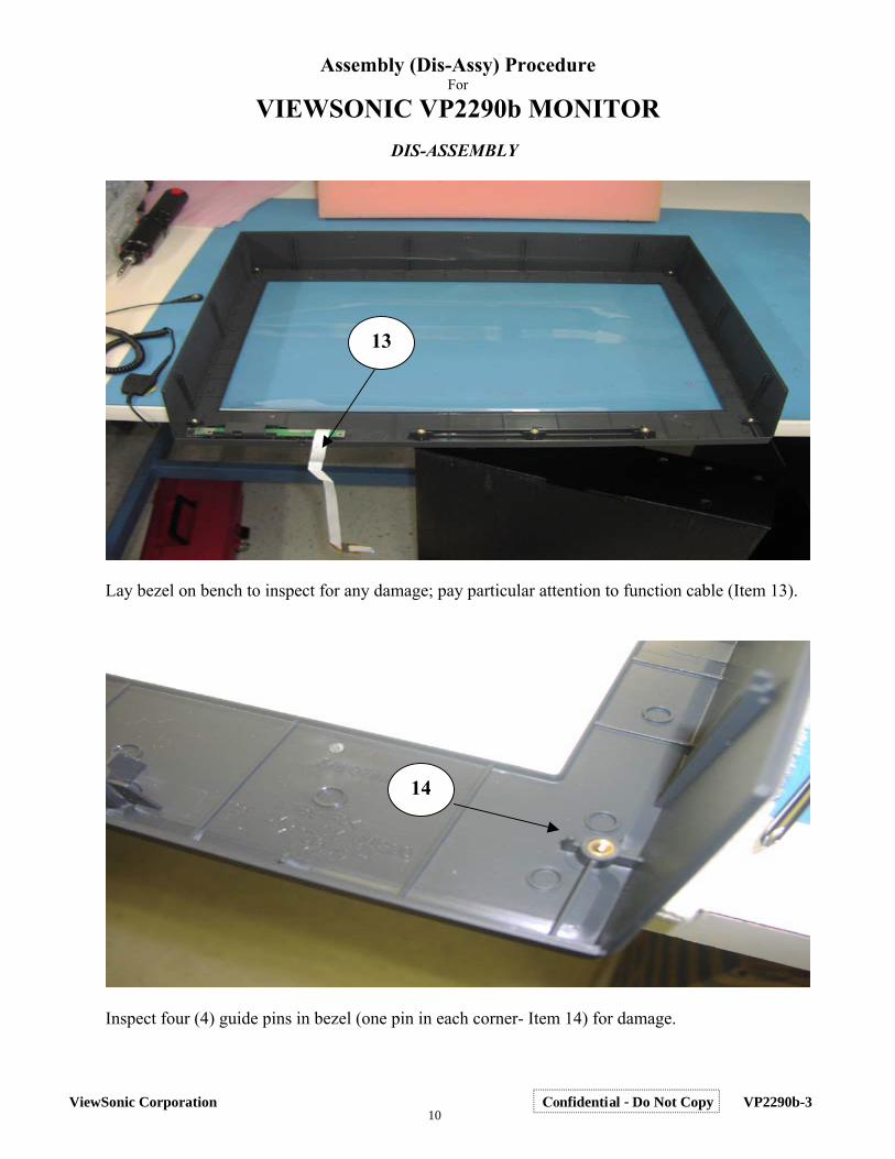
13
Lay bezel on bench to inspect for any damage; pay particular attention to function cable (Item 13).
14
Inspect four (4) guide pins in bezel (one pin in each corner- Item 14) for damage.
10ViewSonic Corporation Confidential - Do Not Copy VP2290b-3
Assembly (Dis-Assy) Procedure For
VIEWSONIC VP2290b MONITOR DIS-ASSEMBLY
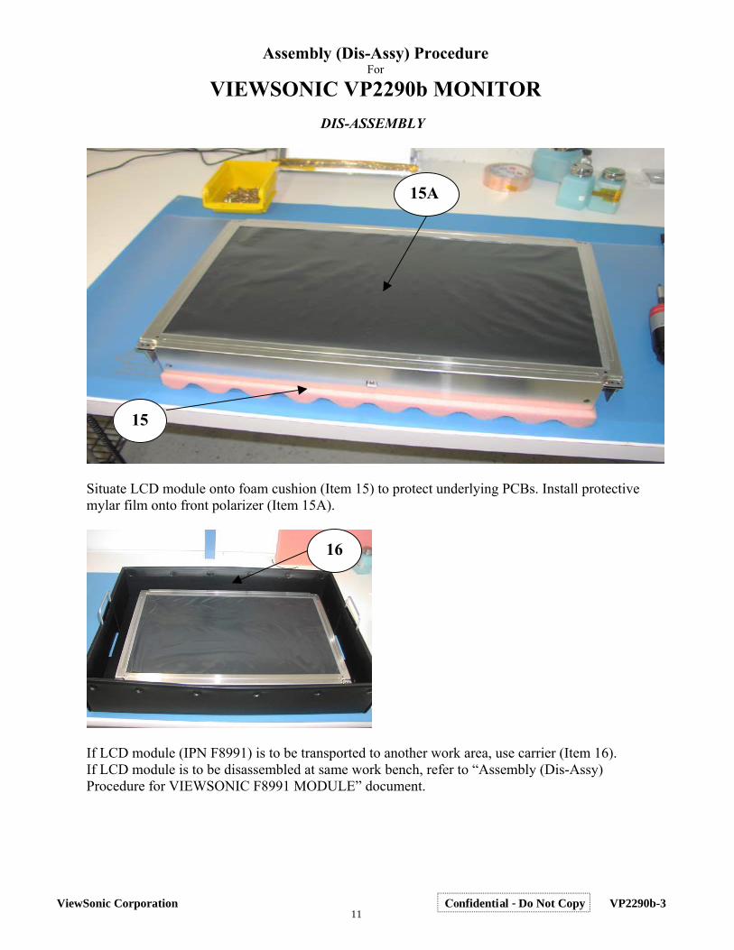
15A
15
Situate LCD module onto foam cushion (Item 15) to protect underlying PCBs. Install protective mylar film onto front polarizer (Item 15A).
16
If LCD module (IPN F8991) is to be transported to another work area, use carrier (Item 16). If LCD module is to be disassembled at same work bench, refer to “Assembly (Dis-Assy) Procedure for VIEWSONIC F8991 MODULE” document.
11ViewSonic Corporation Confidential - Do Not Copy VP2290b-3
Assembly (Dis-Assy) Procedure For
VIEWSONIC VP2290b MONITOR INSTRUCTIONS FOR ASSEMBLY
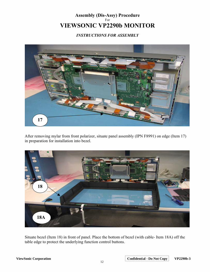
17
After removing mylar from front polarizer, situate panel assembly (IPN F8991) on edge (Item 17) in preparation for installation into bezel.
18
18A
Situate bezel (Item 18) in front of panel. Place the bottom of bezel (with cable- Item 18A) off the table edge to protect the underlying function control buttons.
12ViewSonic Corporation Confidential - Do Not Copy VP2290b-3
Assembly (Dis-Assy) Procedure For
VIEWSONIC VP2290b MONITOR ASSEMBLY
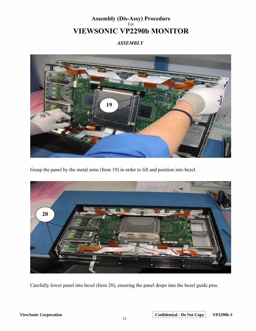
19
Grasp the panel by the metal arms (Item 19) in order to lift and position into bezel.
20
Carefully lower panel into bezel (Item 20), ensuring the panel drops into the bezel guide pins.
13ViewSonic Corporation Confidential - Do Not Copy VP2290b-3
Assembly (Dis-Assy) Procedure For
VIEWSONIC VP2290b MONITOR ASSEMBLY
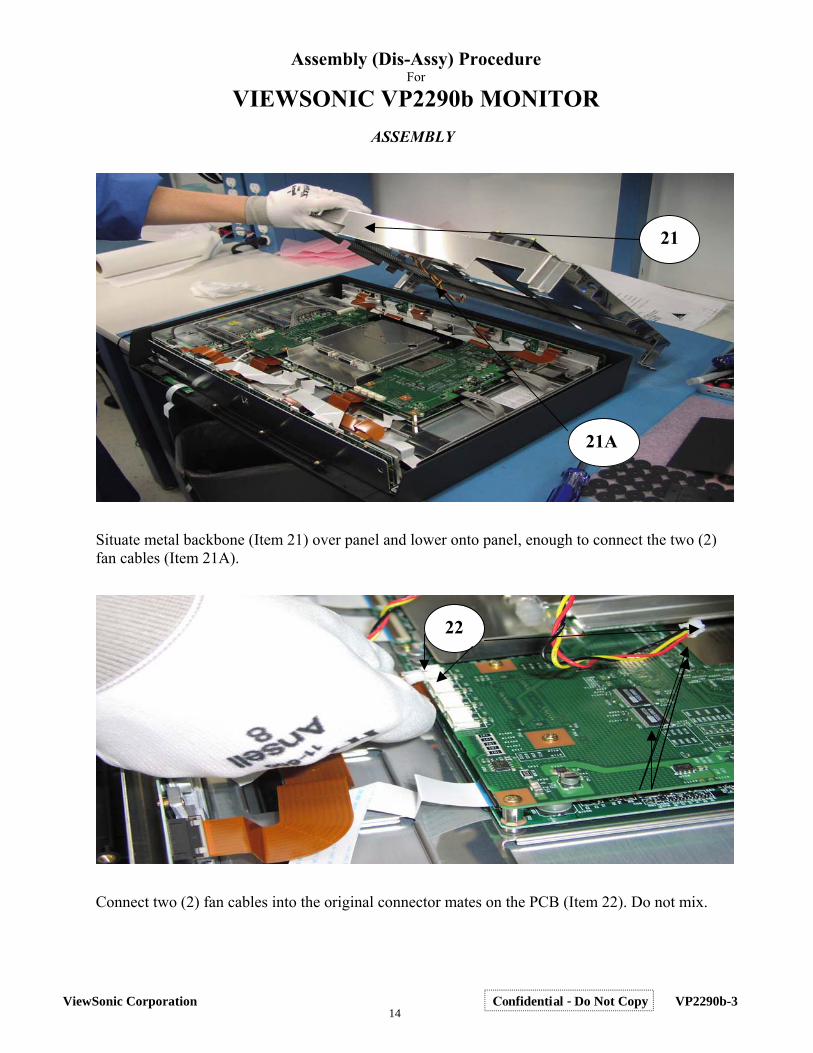
21
21A
Situate metal backbone (Item 21) over panel and lower onto panel, enough to connect the two (2) fan cables (Item 21A).
22
Connect two (2) fan cables into the original connector mates on the PCB (Item 22). Do not mix.
14ViewSonic Corporation Confidential - Do Not Copy VP2290b-3
Assembly (Dis-Assy) Procedure For
VIEWSONIC VP2290b MONITOR ASSEMBLY
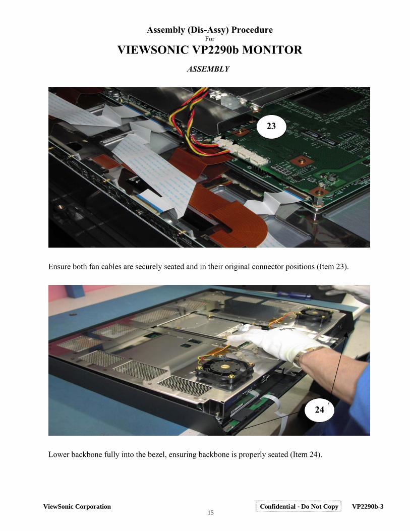
23
Ensure both fan cables are securely seated and in their original connector positions (Item 23).
24
Lower backbone fully into the bezel, ensuring backbone is properly seated (Item 24).
15ViewSonic Corporation Confidential - Do Not Copy VP2290b-3
Assembly (Dis-Assy) Procedure For
VIEWSONIC VP2290b MONITOR ASSEMBLY
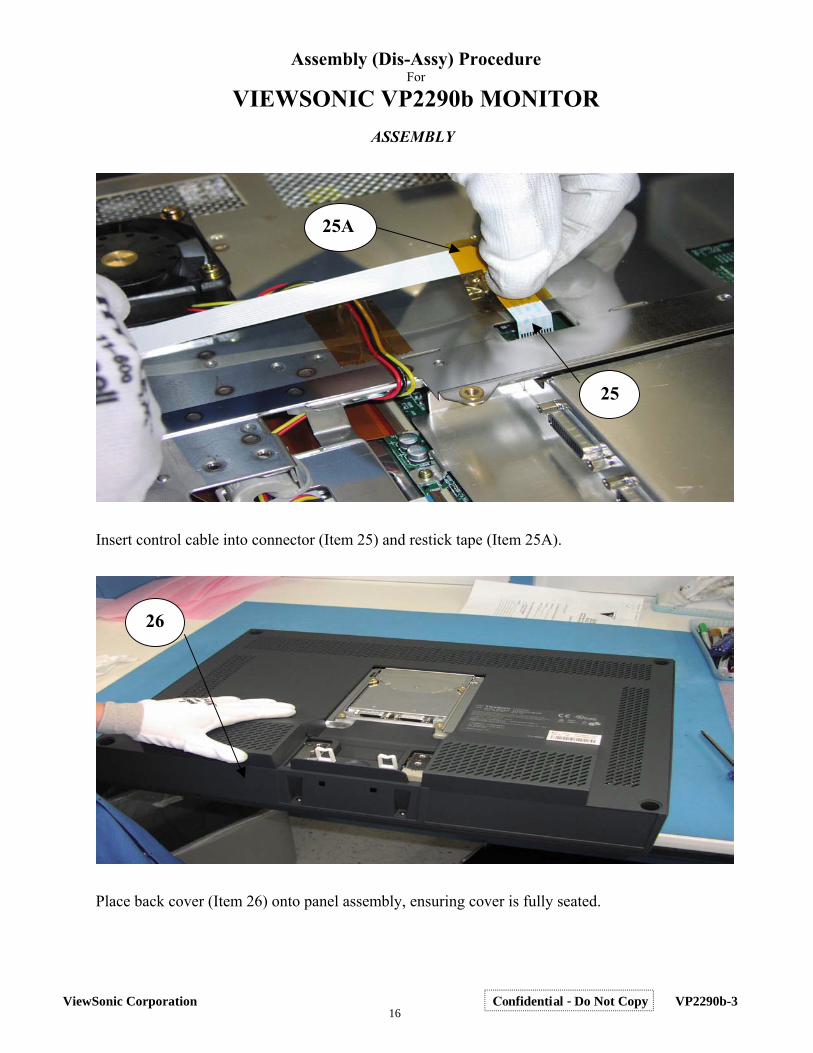
25A
25
Insert control cable into connector (Item 25) and restick tape (Item 25A).
26
Place back cover (Item 26) onto panel assembly, ensuring cover is fully seated.
16ViewSonic Corporation Confidential - Do Not Copy VP2290b-3
Assembly (Dis-Assy) Procedure For
VIEWSONIC VP2290b MONITOR ASSEMBLY
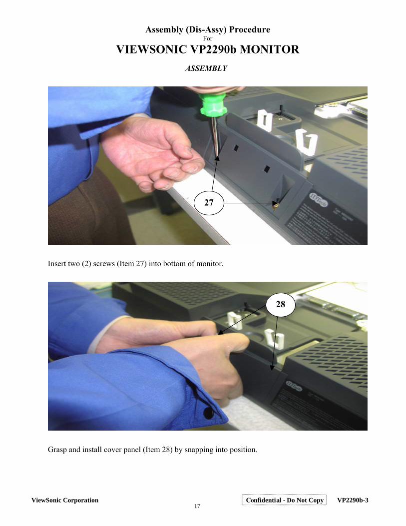
27
Insert two (2) screws (Item 27) into bottom of monitor.
28
Grasp and install cover panel (Item 28) by snapping into position.
17ViewSonic Corporation Confidential - Do Not Copy VP2290b-3
Assembly (Dis-Assy) Procedure For
VIEWSONIC VP2290b MONITOR ASSEMBLY
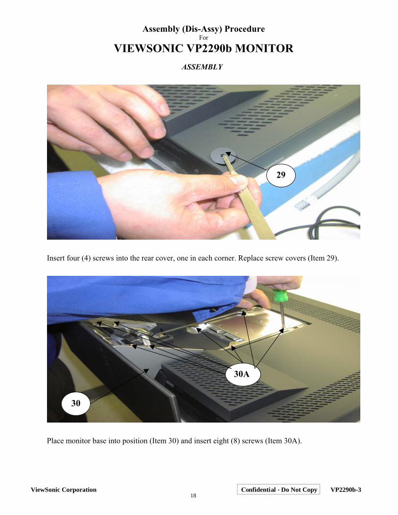
29
Insert four (4) screws into the rear cover, one in each corner. Replace screw covers (Item 29).
30A
30
Place monitor base into position (Item 30) and insert eight (8) screws (Item 30A).
18ViewSonic Corporation Confidential - Do Not Copy VP2290b-3
Assembly (Dis-Assy) Procedure For
VIEWSONIC VP2290b MONITOR ASSEMBLY
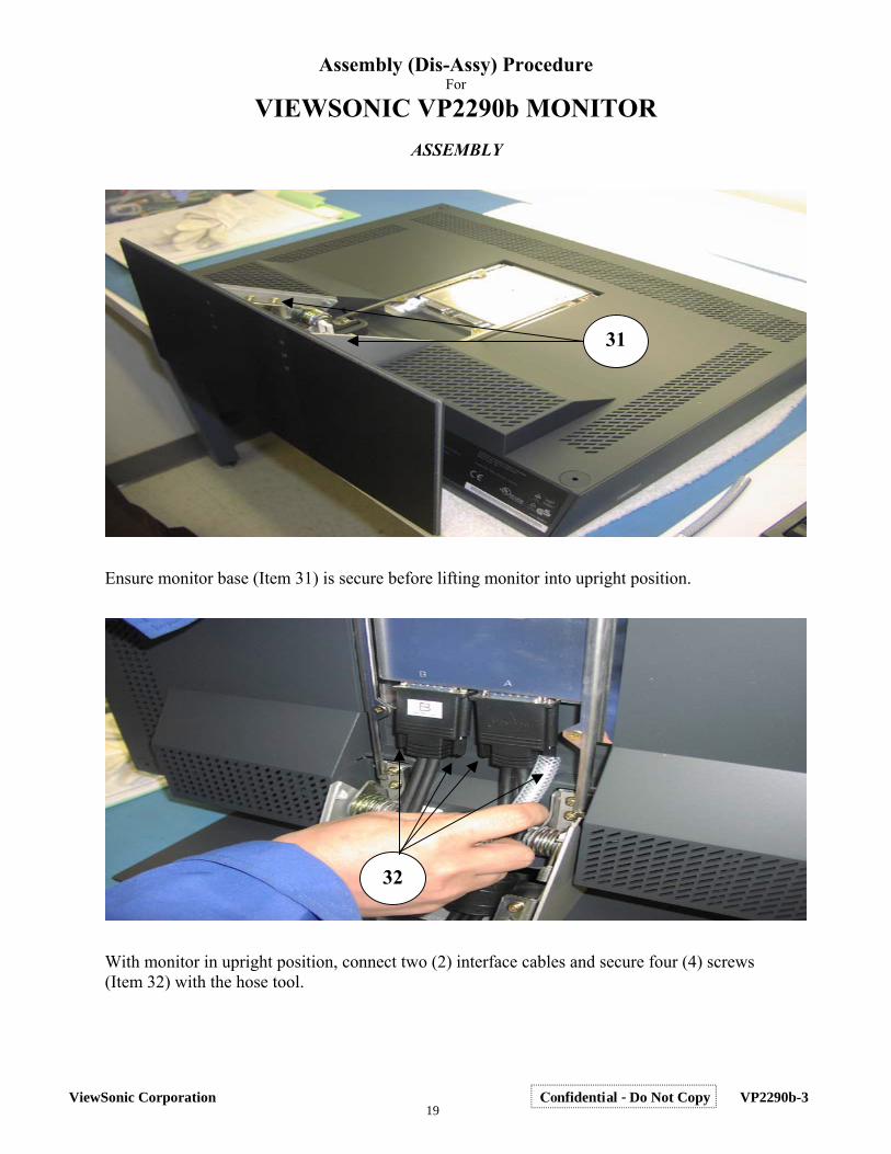
31
Ensure monitor base (Item 31) is secure before lifting monitor into upright position.
32
With monitor in upright position, connect two (2) interface cables and secure four (4) screws (Item 32) with the hose tool.
19ViewSonic Corporation Confidential - Do Not Copy VP2290b-3
Assembly (Dis-Assy) Procedure For
VIEWSONIC VP2290b MONITOR ASSEMBLY
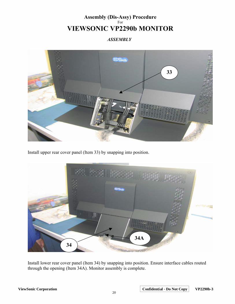
33
Install upper rear cover panel (Item 33) by snapping into position.
34A 34
Install lower rear cover panel (Item 34) by snapping into position. Ensure interface cables routed through the opening (Item 34A). Monitor assembly is complete.
20ViewSonic Corporation Confidential - Do Not Copy VP2290b-3
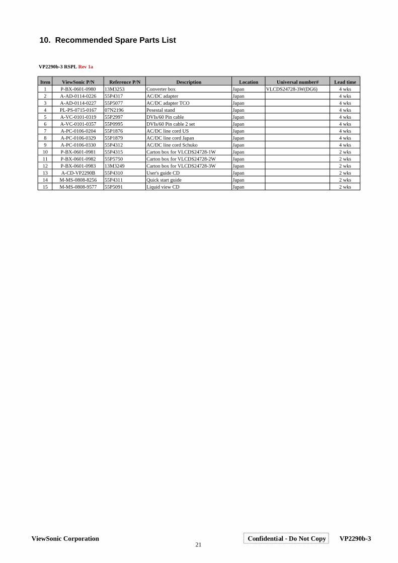
Item ViewSonic P/N Reference P/N Description Location Universal number# Lead time1 P-BX-0601-0980 13M3253 Converter box Japan VLCDS24728-3W(DG6) 4 wks2 A-AD-0114-0226 55P4317 AC/DC adapter Japan 4 wks3 A-AD-0114-0227 55P5077 AC/DC adapter TCO Japan 4 wks4 PL-PS-0715-0167 07N2196 Pesestal stand Japan 4 wks5 A-VC-0101-0319 55P2997 DVIs/60 Pin cable Japan 4 wks6 A-VC-0101-0357 55P0995 DVIs/60 Pin cable 2 set Japan 4 wks7 A-PC-0106-0204 55P1876 AC/DC line cord US Japan 4 wks8 A-PC-0106-0329 55P1879 AC/DC line cord Japan Japan 4 wks9 A-PC-0106-0330 55P4312 AC/DC line cord Schuko Japan 4 wks
10 P-BX-0601-0981 55P4315 Carton box for VLCDS24728-1W Japan 2 wks11 P-BX-0601-0982 55P5750 Carton box for VLCDS24728-2W Japan 2 wks12 P-BX-0601-0983 13M3249 Carton box for VLCDS24728-3W Japan 2 wks13 A-CD-VP2290B 55P4310 User's guide CD Japan 2 wks14 M-MS-0808-8256 55P4311 Quick start guide Japan 2 wks15 M-MS-0808-9577 55P5091 Liquid view CD Japan 2 wks
VP2290b-3 RSPL Rev 1a
10. Recommended Spare Parts List
21ViewSonic Corporation Confidential - Do Not Copy VP2290b-3
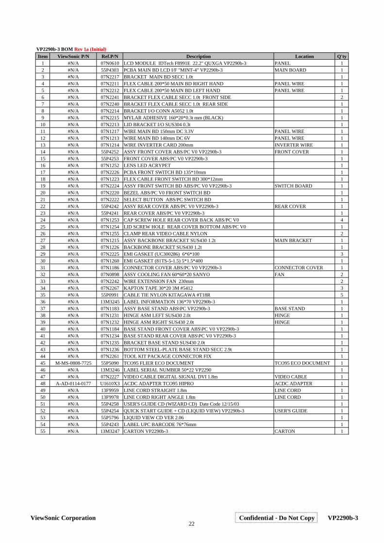
Item ViewSonic P/N Ref.P/N Description Location Q'ty1 #N/A 07N0610 LCD MODULE IDTech F8991E 22.2" QUXGA VP2290b-3 PANEL 12 #N/A 55P4303 PCBA MAIN BD LCD I/F "MINT-4" VP2290b-3 MAIN BOARD 13 #N/A 07N2217 BRACKET MAIN BD SECC 1.0t 14 #N/A 07N2211 FLEX CABLE 200*50 MAIN BD RIGHT HAND PANEL WIRE 15 #N/A 07N2212 FLEX CABLE 200*50 MAIN BD LEFT HAND PANEL WIRE 16 #N/A 07N2241 BRACKET FLEX CABLE SECC 1.0t FRONT SIDE 27 #N/A 07N2240 BRACKET FLEX CABLE SECC 1.0t REAR SIDE 18 #N/A 07N2214 BRACKET I/O CONN A5052 1.0t 19 #N/A 07N2215 MYLAR ADHESIVE 160*20*0.3t mm (BLACK) 110 #N/A 07N2213 LID BRACKET I/O SUS304 0.3t 111 #N/A 07N1217 WIRE MAIN BD 150mm DC 3.3V PANEL WIRE 112 #N/A 07N1213 WIRE MAIN BD 140mm DC 6V PANEL WIRE 113 #N/A 07N1214 WIRE INVERTER CARD 200mm INVERTER WIRE 114 #N/A 55P4252 ASSY FRONT COVER ABS/PC V0 VP2290b-3 FRONT COVER 115 #N/A 55P4253 FRONT COVER ABS/PC V0 VP2290b-3 116 #N/A 07N1252 LENS LED ACRYPET 117 #N/A 07N2226 PCBA FRONT SWITCH BD 135*10mm 118 #N/A 07N1223 FLEX CABLE FRONT SWITCH BD 300*12mm 119 #N/A 07N2224 ASSY FRONT SWITCH BD ABS/PC V0 VP2290b-3 SWITCH BOARD 120 #N/A 07N2220 BEZEL ABS/PC V0 FRONT SWITCH BD 121 #N/A 07N2222 SELECT BUTTON ABS/PC SWITCH BD 122 #N/A 55P4242 ASSY REAR COVER ABS/PC V0 VP2290b-3 REAR COVER 123 #N/A 55P4241 REAR COVER ABS/PC V0 VP2290b-3 124 #N/A 07N1253 CAP SCREW HOLE REAR COVER BACK ABS/PC V0 425 #N/A 07N1254 LID SCREW HOLE REAR COVER BOTTOM ABS/PC V0 126 #N/A 07N1255 CLAMP REAR VIDEO CABLE NYLON 227 #N/A 07N1215 ASSY BACKBONE BRACKET SUS430 1.2t MAIN BRACKET 128 #N/A 07N1226 BACKBONE BRACKET SUS430 1.2t 129 #N/A 07N2225 EMI GASKET (UC300286) 6*6*100 330 #N/A 07N1260 EMI GASKET (81TS-5-1.5) 5*1.5*400 131 #N/A 07N1186 CONNECTOR COVER ABS/PC V0 VP2290b-3 CONNECTOR COVER 132 #N/A 07N0898 ASSY COOLING FAN 60*60*20 SANYO FAN 233 #N/A 07N2242 WIRE EXTENSION FAN 230mm 234 #N/A 07N2267 KAPTON TAPE 30*20 3M #5412 335 #N/A 55P0991 CABLE TIE NYLON KITAGAWA #T18R 536 #N/A 13M3245 LABEL INFORMATION 136*70 VP2290b-3 137 #N/A 07N1183 ASSY BASE STAND ABS\PC VP2290b-3 BASE STAND 138 #N/A 07N1231 HINGE ASM LEFT SUS430 2.0t HINGE 139 #N/A 07N1232 HINGE ASM RIGHT SUS430 2.0t HINGE 140 #N/A 07N1184 BASE STAND FRONT COVER ABS\PC V0 VP2290b-3 141 #N/A 07N1234 BASE STAND REAR COVER ABS\PC V0 VP2290b-3 142 #N/A 07N1235 BRACKET BASE STAND SUS430 2.0t 143 #N/A 07N1236 BOTTOM STEEL-PLATE BASE STAND SECC 2.9t 144 #N/A 07N2261 TOOL KIT PACKAGE CONNECTOR FIX 145 M-MS-0808-7725 55P5090 TCO95 FLIER ECO DOCUMENT TCO95 ECO DOCUMENT 146 #N/A 13M3246 LABEL SERIAL NUMBER 50*22 VP2290 147 #N/A 07N2227 VIDEO CABLE DIGITAL SIGNAL DVI 1.8m VIDEO CABLE 148 A-AD-0114-0177 U1610X3 ACDC ADAPTER TCO95 HIPRO ACDC ADAPTER 149 #N/A 13F9959 LINE CORD STRAIGHT 1.8m LINE CORD 150 #N/A 13F9978 LINE CORD RIGHT ANGLE 1.8m LINE CORD 151 #N/A 55P4258 USER'S GUIDE CD (WIZARD CD) Date Code 12/15/03 152 #N/A 55P4254 QUICK START GUIDE + CD (LIQUID VIEW) VP2290b-3 USER'S GUIDE 153 #N/A 55P5796 LIQUID VIEW CD VER 2.06 154 #N/A 55P4243 LABEL UPC BARCODE 76*76mm 155 #N/A 13M3247 CARTON VP2290b-3 CARTON 1
VP2290b-3 BOM Rev 1a (Initial)
22ViewSonic Corporation Confidential - Do Not Copy VP2290b-3
����������������������-��&���,
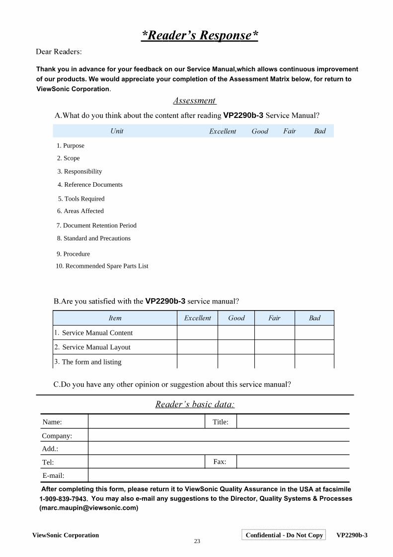
Thank you in advance for your feedback on our Service Manual,which allows continuous improvement
of our products. We would appreciate your completion of the Assessment Matrix below, for return to
ViewSonic Corporation�
����������
8���������"�����&#�"�"��VP2290b-3���B�)� �!��D
���������B��!��"������!��!����..��"��!����""������B�)� �!��D
������� ���������
�After completing this form, please return it to ViewSonic Quality Assurance
��4��"&����"��!*����""��)�!"�!"��"�����&�!.VP2290b-3 ���B�)�5�!��D
���� ��������� ��� ��� ��
��
��
��
���� ��� ��
in the USA at facsimile 1-909-839-7943. You may also e-mail any suggestions to the Director, Quality Systems & Processes([email protected])
������������
Service Manual Content
Service Manual Layout
The form and listing
Name: Title:
Company:
Add.:
Tel:
E-mail:
Fax:
1. Purpose
2. Scope
3. Responsibility
4. Reference Documents
5. Tools Required
6. Areas Affected
7. Document Retention Period
8. Standard and Precautions
9. Procedure
10. Recommended Spare Parts List
23ViewSonic Corporation Confidential - Do Not Copy VP2290b-3
Recommended