ASFPM 2015 National Conference
Don’t Hold Anything Back: Tennessee Tombigbee Waterway LAMP Pilot Project
Michael Taylor, AECOM/MGI
Stephen Champlin, MDEQ
June 4, 2015
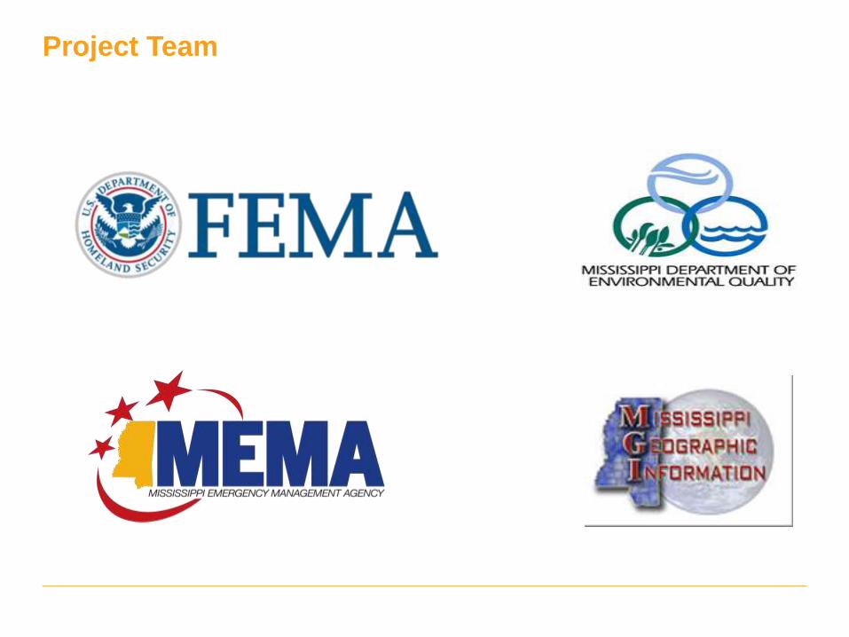
Project Team
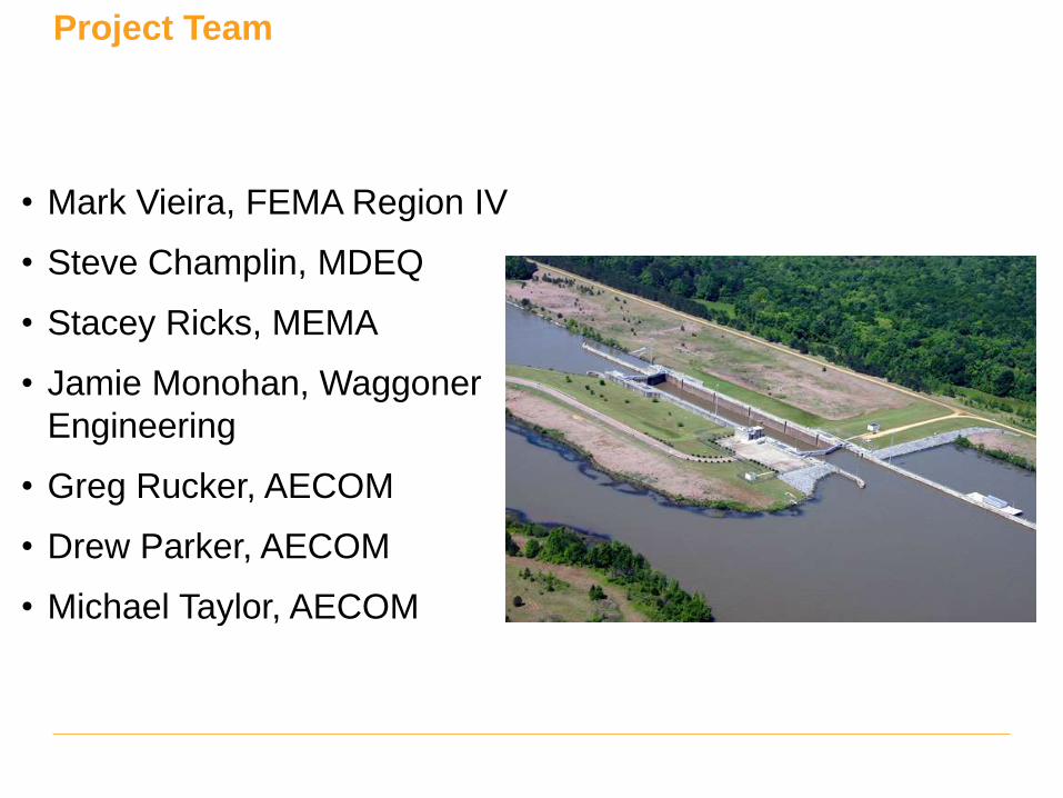
Project Team
• Mark Vieira, FEMA Region IV
• Steve Champlin, MDEQ
• Stacey Ricks, MEMA
• Jamie Monohan, Waggoner
Engineering
• Greg Rucker, AECOM
• Drew Parker, AECOM
• Michael Taylor, AECOM
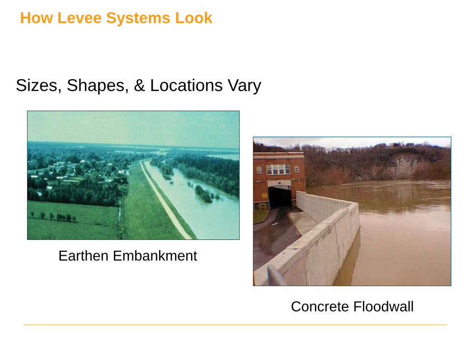
How Levee Systems Look
Sizes, Shapes, & Locations Vary
Earthen Embankment
Concrete Floodwall
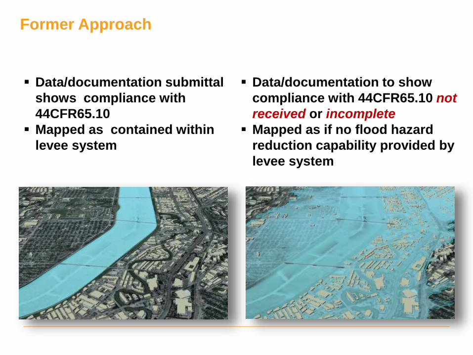
Former Approach
Data/documentation submittal
shows compliance with
44CFR65.10
Mapped as contained within
levee system
Data/documentation to show
compliance with 44CFR65.10 not
received or incomplete
Mapped as if no flood hazard
reduction capability provided by
levee system
Project History
• Monroe County, Mississippi and Itawamba County, Mississippi had preliminary maps issued during Map Modernization (March 4, 2010).
• Levee system could not be accredited. No new analysis performed on Tombigbee/TennTom upstream of Amory.
• Monroe and Itawamba county preliminary maps issued without levee providing protection.
• City of Fulton submitted appeal data on December 2, 2010
• Monroe County and City of Amory submitted appeal data on December 30, 2010

Project History
• On March 10, 2011 FEMA put these types of projects on hold pending finalized Levee Analysis and Mapping Procedures (LAMP) guidance.
• LiDAR collected for the area.
• Levee system selected as one of 25 pilot projects nationwide.
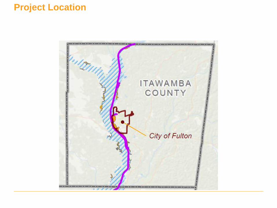
Project Location

Project Location
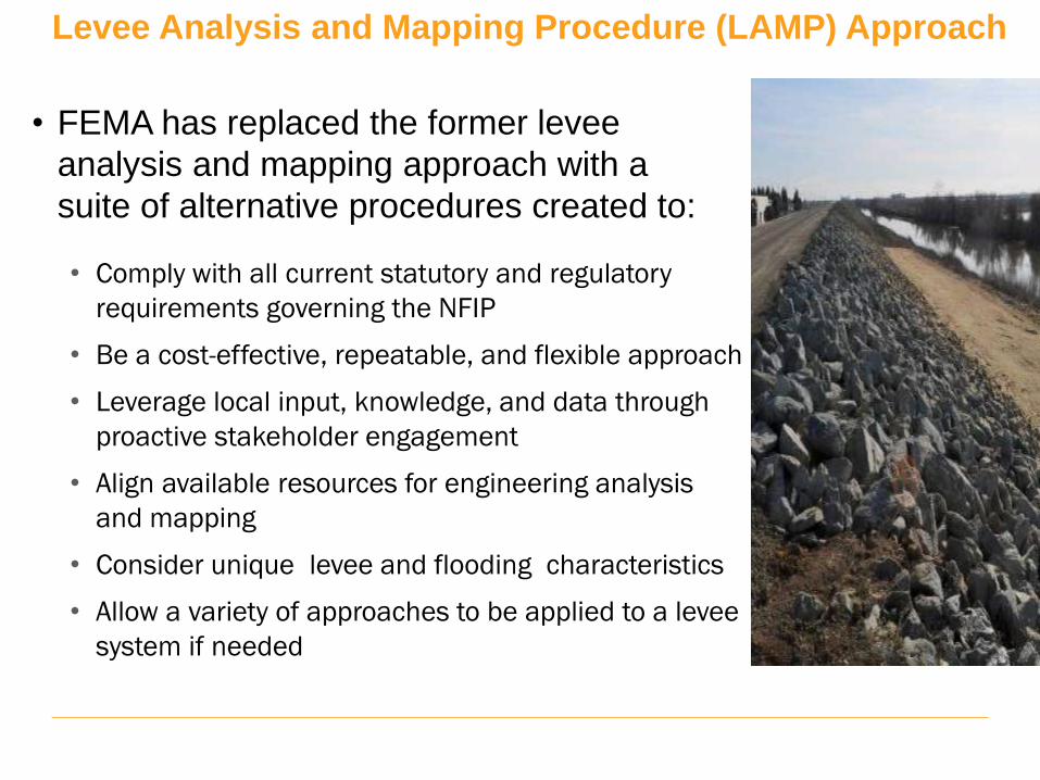
Levee Analysis and Mapping Procedure (LAMP) Approach
• FEMA has replaced the former levee
analysis and mapping approach with a
suite of alternative procedures created to:
• Comply with all current statutory and regulatory
requirements governing the NFIP
• Be a cost-effective, repeatable, and flexible approach
• Leverage local input, knowledge, and data through
proactive stakeholder engagement
• Align available resources for engineering analysis
and mapping
• Consider unique levee and flooding characteristics
• Allow a variety of approaches to be applied to a levee
system if needed
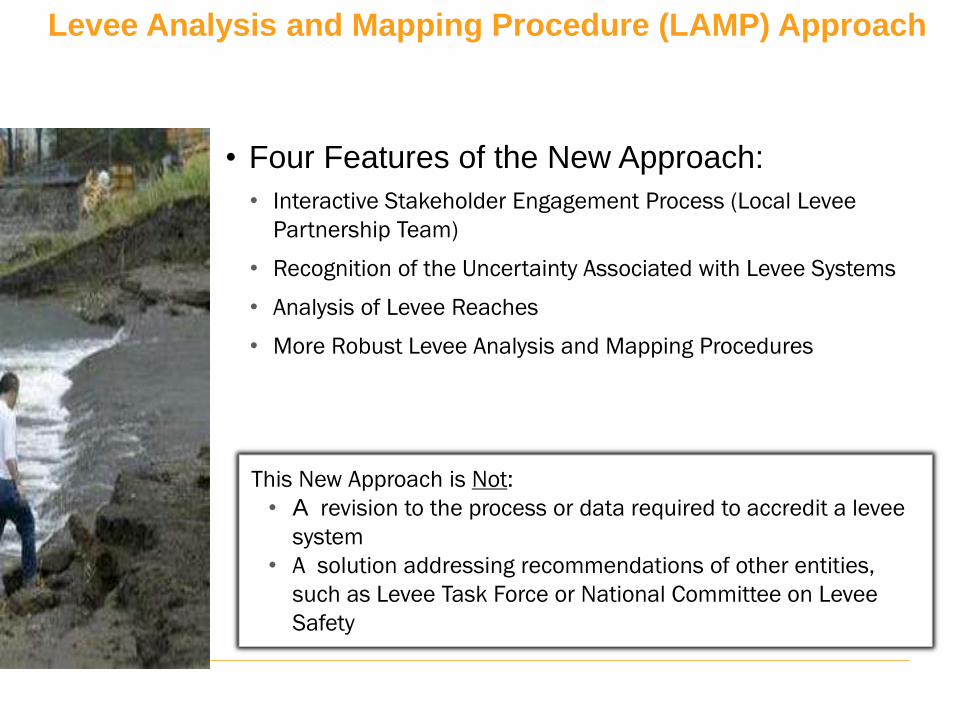
• Four Features of the New Approach:
• Interactive Stakeholder Engagement Process (Local Levee
Partnership Team)
• Recognition of the Uncertainty Associated with Levee Systems
• Analysis of Levee Reaches
• More Robust Levee Analysis and Mapping Procedures
This New Approach is Not:
• A revision to the process or data required to accredit a levee
system
• A solution addressing recommendations of other entities,
such as Levee Task Force or National Committee on Levee
Safety
Levee Analysis and Mapping Procedure (LAMP) Approach
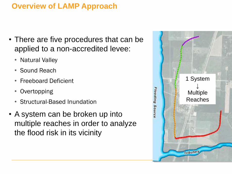
Overview of LAMP Approach
• There are five procedures that can be
applied to a non-accredited levee:
• Natural Valley
• Sound Reach
• Freeboard Deficient
• Overtopping
• Structural-Based Inundation
• A system can be broken up into
multiple reaches in order to analyze
the flood risk in its vicinity
1 System
↓
Multiple
Reaches
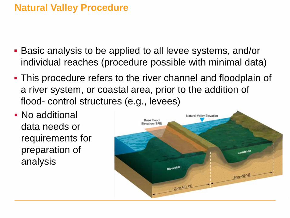
Natural Valley Procedure
Basic analysis to be applied to all levee systems, and/or
individual reaches (procedure possible with minimal data)
This procedure refers to the river channel and floodplain of
a river system, or coastal area, prior to the addition of
flood- control structures (e.g., levees)
No additional
data needs or
requirements for
preparation of
analysis
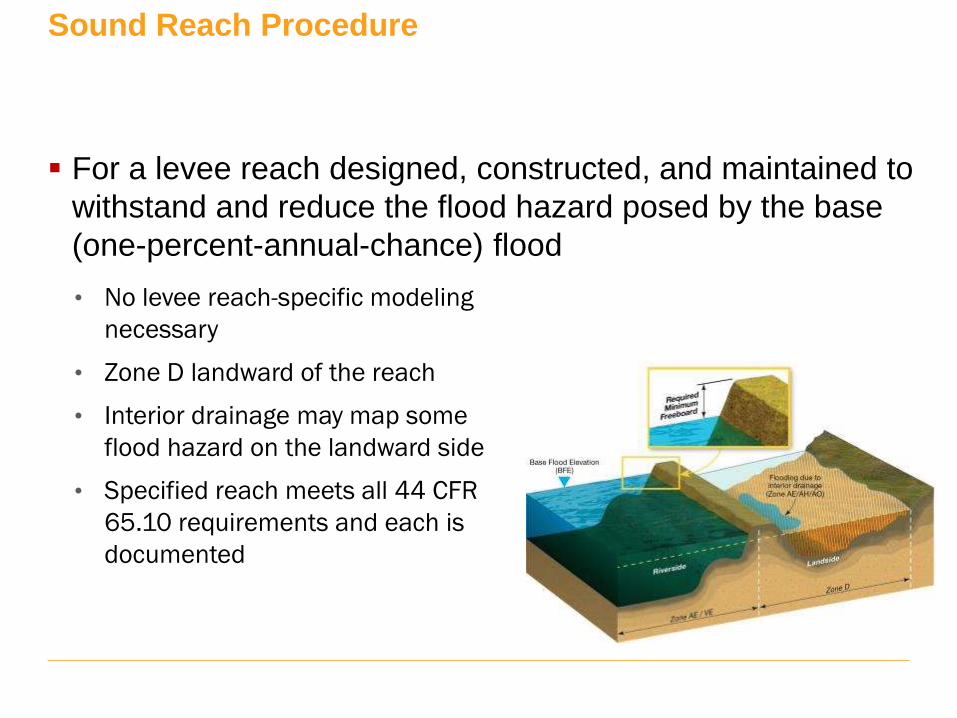
Sound Reach Procedure
• No levee reach-specific modeling
necessary
• Zone D landward of the reach
• Interior drainage may map some
flood hazard on the landward side
• Specified reach meets all 44 CFR
65.10 requirements and each is
documented
For a levee reach designed, constructed, and maintained to
withstand and reduce the flood hazard posed by the base
(one-percent-annual-chance) flood
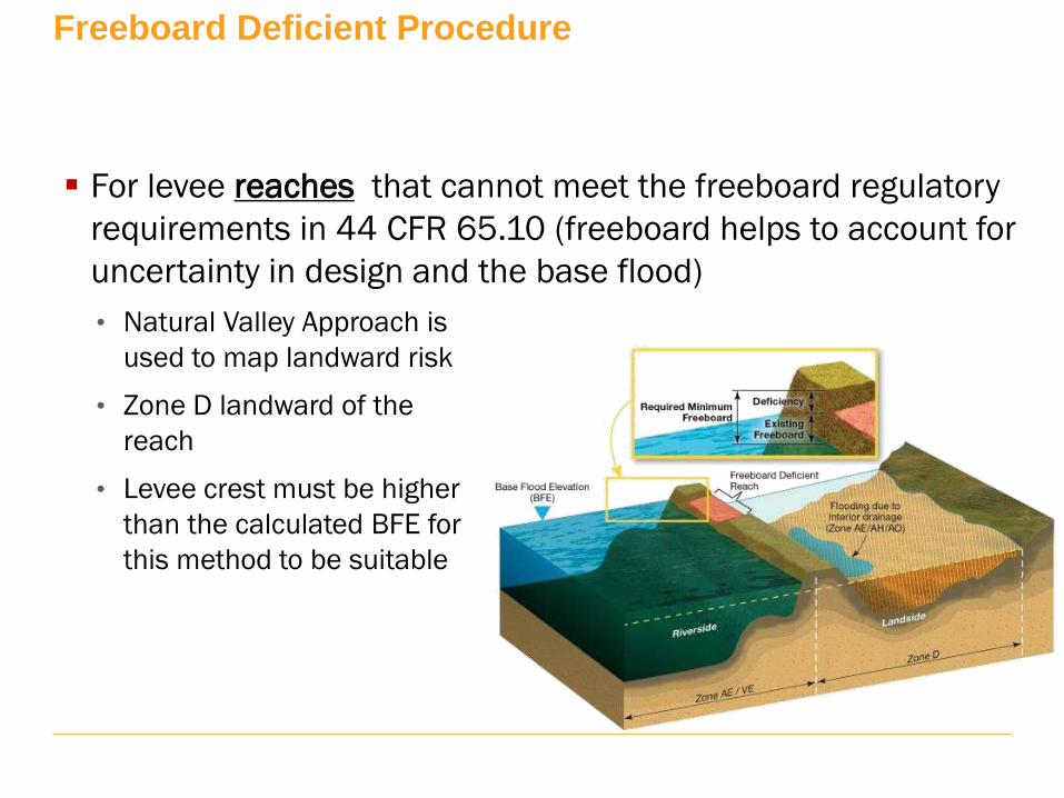
Freeboard Deficient Procedure
For levee reaches that cannot meet the freeboard regulatory
requirements in 44 CFR 65.10 (freeboard helps to account for
uncertainty in design and the base flood)
• Natural Valley Approach is
used to map landward risk
• Zone D landward of the
reach
• Levee crest must be higher
than the calculated BFE for
this method to be suitable

Overtopping Procedure
Appropriate for levee reaches that are known to overtop during
the one-percent-annual chance flood.
The BFE is calculated to exceed the height of the levee crest
at a minimum of one location along the levee’s reach length)
Structure should be
designed for
overtopping
Structural requirements
are met and
documented
Levee modeled as a
lateral weir
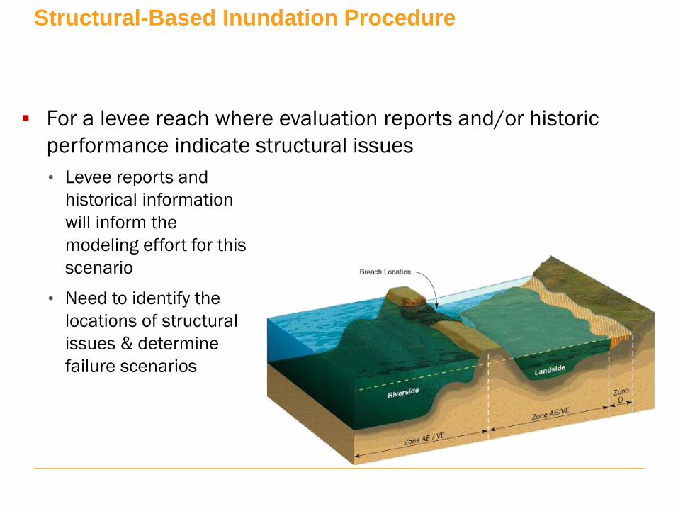
Structural-Based Inundation Procedure
For a levee reach where evaluation reports and/or historic
performance indicate structural issues
• Levee reports and
historical information
will inform the
modeling effort for this
scenario
• Need to identify the
locations of structural
issues & determine
failure scenarios
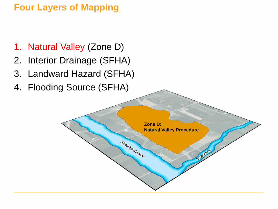
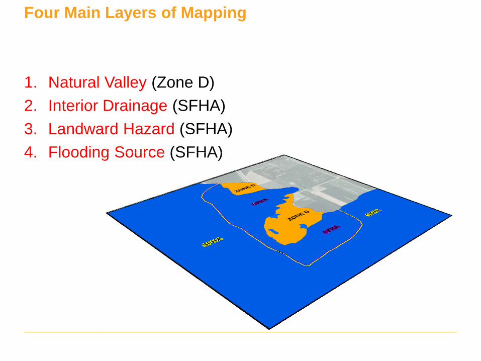
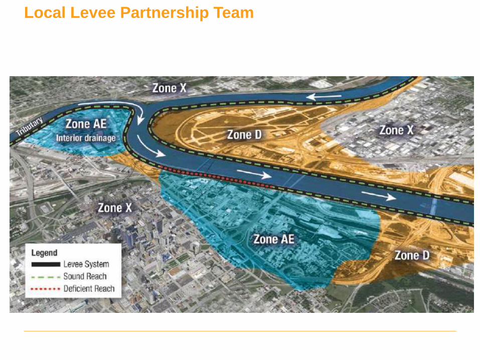
1. Natural Valley (Zone D)
2. Interior Drainage (SFHA)
3. Landward Hazard (SFHA)
4. Flooding Source (SFHA)
Four Layers of Mapping
Zone D:
Natural Valley Procedure
1. Natural Valley (Zone D)
2. Interior Drainage (SFHA)
3. Landward Hazard (SFHA)
4. Flooding Source (SFHA)
Four Main Layers of Mapping
Interior Drainage SFHA
with System in Place
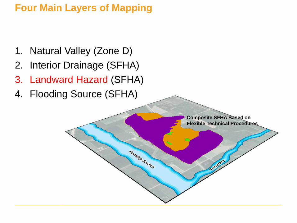
1. Natural Valley (Zone D)
2. Interior Drainage (SFHA)
3. Landward Hazard (SFHA)
4. Flooding Source (SFHA)
Four Main Layers of Mapping
Composite SFHA Based on
Flexible Technical Procedures
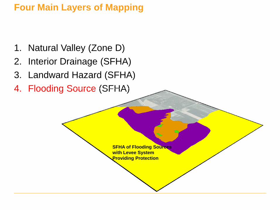
1. Natural Valley (Zone D)
2. Interior Drainage (SFHA)
3. Landward Hazard (SFHA)
4. Flooding Source (SFHA)
Four Main Layers of Mapping
SFHA of Flooding Sources
with Levee System
Providing Protection
1. Natural Valley (Zone D)
2. Interior Drainage (SFHA)
3. Landward Hazard (SFHA)
4. Flooding Source (SFHA)
Four Main Layers of Mapping
SFHA of Flooding Sources
with Levee System
Providing Protection
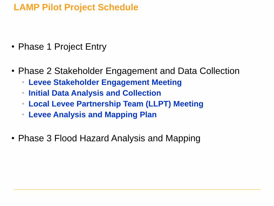
LAMP Pilot Project Schedule
• Phase 1 Project Entry
• Phase 2 Stakeholder Engagement and Data Collection
• Levee Stakeholder Engagement Meeting
• Initial Data Analysis and Collection
• Local Levee Partnership Team (LLPT) Meeting
• Levee Analysis and Mapping Plan
• Phase 3 Flood Hazard Analysis and Mapping
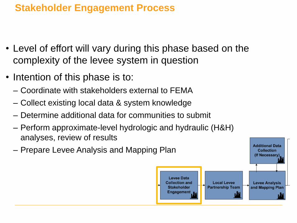
Stakeholder Engagement Process
• Level of effort will vary during this phase based on the
complexity of the levee system in question
• Intention of this phase is to:
– Coordinate with stakeholders external to FEMA
– Collect existing local data & system knowledge
– Determine additional data for communities to submit
– Perform approximate-level hydrologic and hydraulic (H&H)
analyses, review of results
– Prepare Levee Analysis and Mapping Plan
Collaboration with USACE
• Project Team met with USACE on January 9, 2014 in Mobile
• USACE asked to be included in the Local Levee Partnership Team (LLPT)
• Verified the entire system could not be accredited to the 1% annual chance flood event
• Several portions are operated, maintained, and inspected and may be considered sound reaches
• Portions of the structure that are not maintained or inspected will be considered natural valley reaches
Data Collection and Stakeholder Engagement Meeting
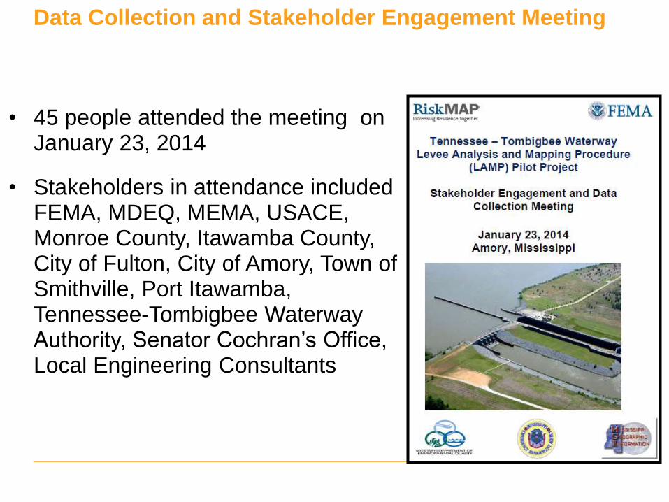
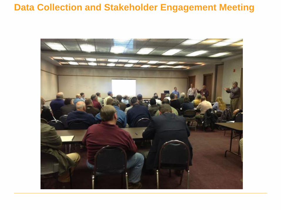
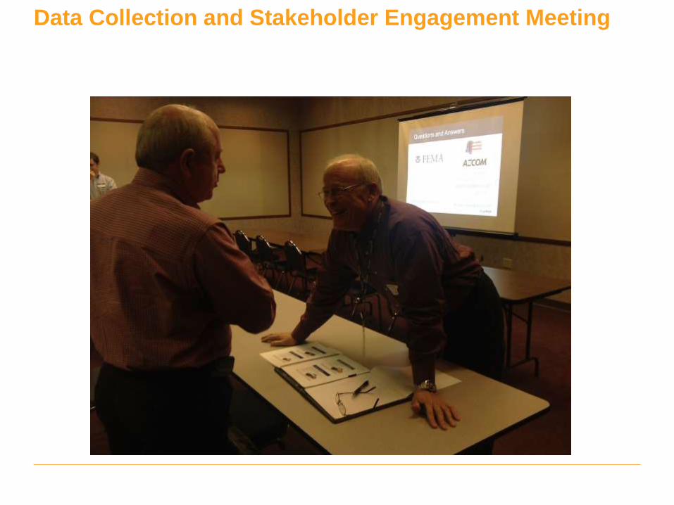
• 45 people attended the meeting on January 23, 2014
• Stakeholders in attendance included FEMA, MDEQ, MEMA, USACE, Monroe County, Itawamba County, City of Fulton, City of Amory, Town of Smithville, Port Itawamba, Tennessee-Tombigbee Waterway Authority, Senator Cochran’s Office, Local Engineering Consultants

Data Collection and Stakeholder Engagement Meeting
Data Collection and Stakeholder Engagement Meeting
Data Collection and Stakeholder Engagement Meeting
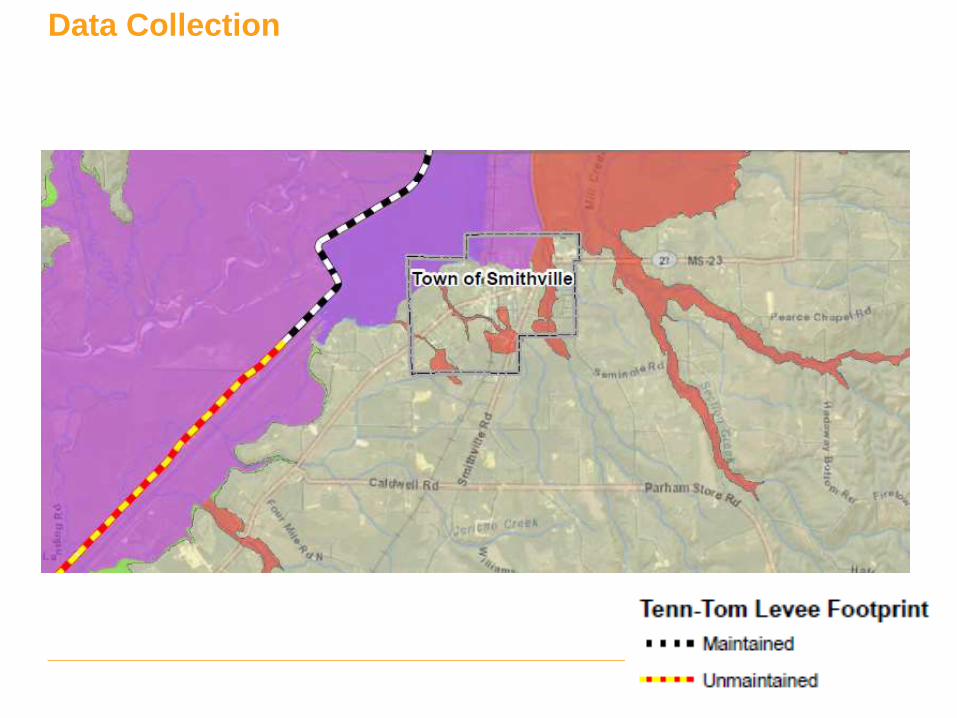
Data Collection
• LiDAR Data for Project Study Area
• Tennessee Tombigbee Waterway Hydrologic and Hydraulic Reports (USACE)
• Tennessee Tombigbee Waterway Design Memorandum (USACE)
• Tennessee Tombigbee River Basin Regulation Manual (USACE)
• Tennessee Tombigbee Waterway Vegetation Assessment (USACE)
• Tennessee Tombigbee Shapefiles
Data Collection
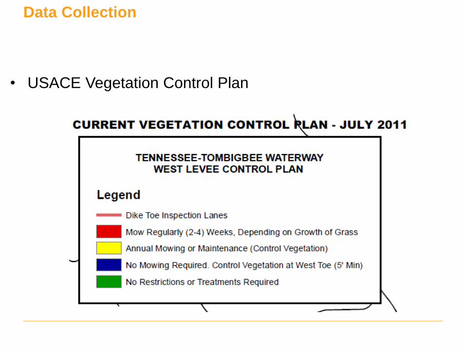
• USACE Vegetation Control Plan
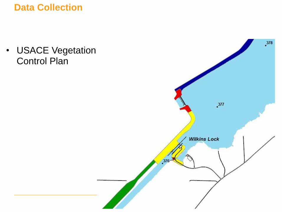
Data Collection
• USACE Vegetation Control Plan
Data Collection
Local Levee Partnership Team
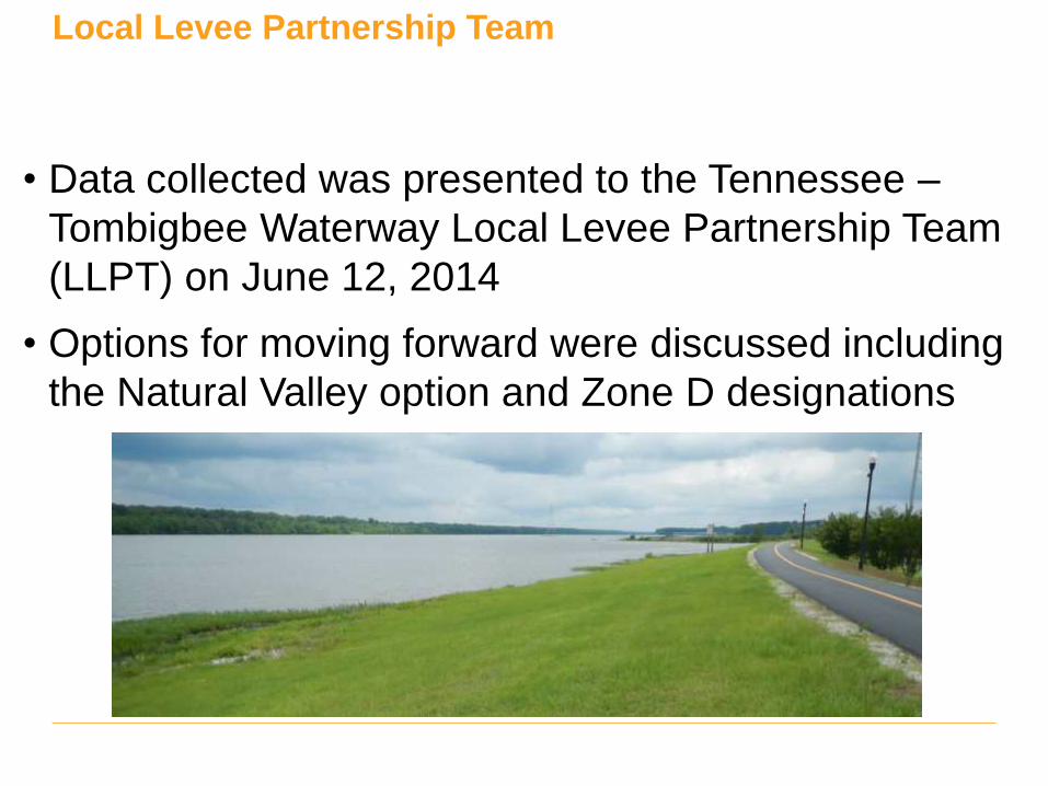
• Data collected was presented to the Tennessee –
Tombigbee Waterway Local Levee Partnership Team
(LLPT) on June 12, 2014
• Options for moving forward were discussed including
the Natural Valley option and Zone D designations
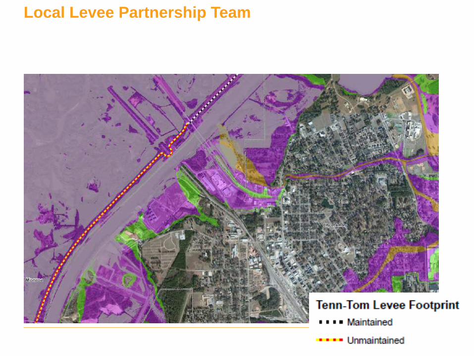
Local Levee Partnership Team
Local Levee Partnership Team
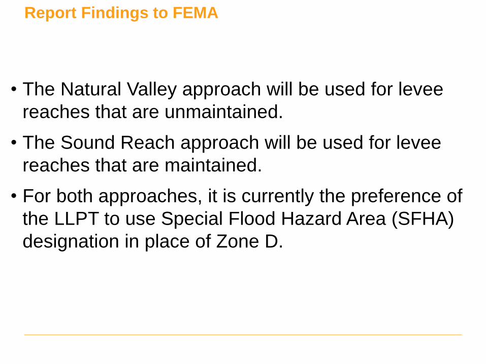
Report Findings to FEMA
• The Natural Valley approach will be used for levee
reaches that are unmaintained.
• The Sound Reach approach will be used for levee
reaches that are maintained.
• For both approaches, it is currently the preference of
the LLPT to use Special Flood Hazard Area (SFHA)
designation in place of Zone D.
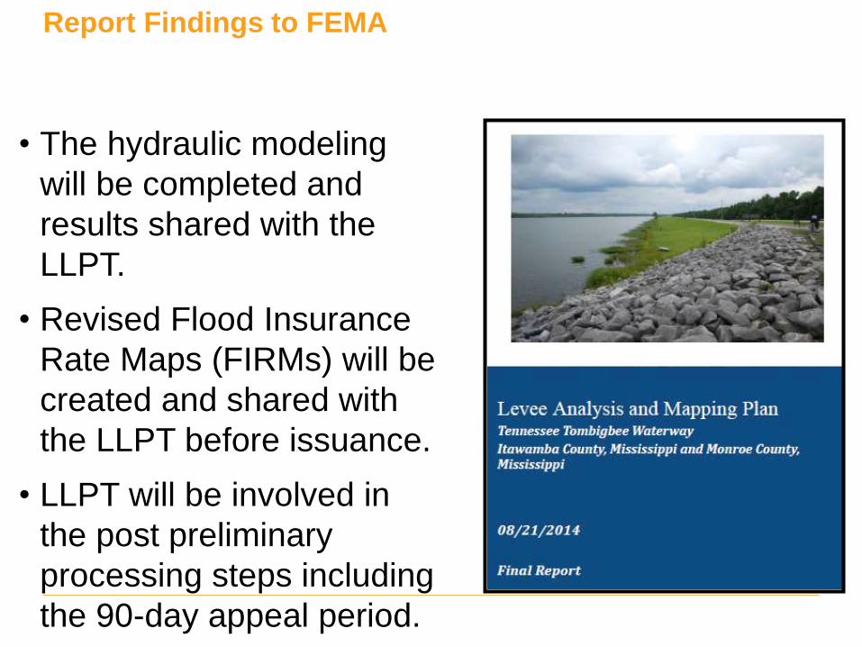
Report Findings to FEMA
• The hydraulic modeling
will be completed and
results shared with the
LLPT.
• Revised Flood Insurance
Rate Maps (FIRMs) will be
created and shared with
the LLPT before issuance.
• LLPT will be involved in
the post preliminary
processing steps including
the 90-day appeal period.
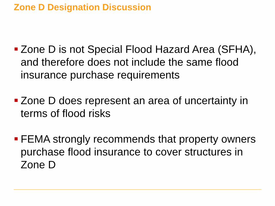
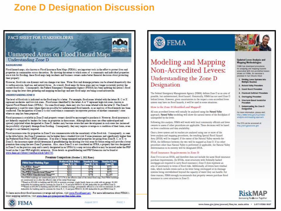
Zone D Designation Discussion
Zone D is not Special Flood Hazard Area (SFHA),
and therefore does not include the same flood
insurance purchase requirements
Zone D does represent an area of uncertainty in
terms of flood risks
FEMA strongly recommends that property owners
purchase flood insurance to cover structures in
Zone D
Zone D Designation Discussion
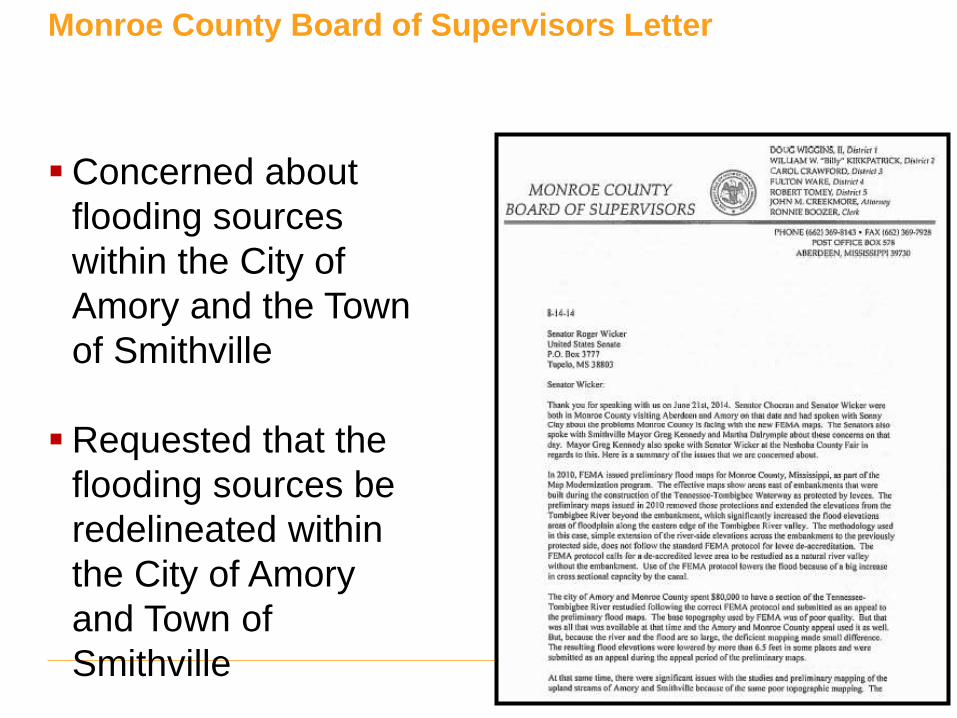
Monroe County Board of Supervisors Letter
Concerned about
flooding sources
within the City of
Amory and the Town
of Smithville
Requested that the
flooding sources be
redelineated within
the City of Amory
and Town of
Smithville
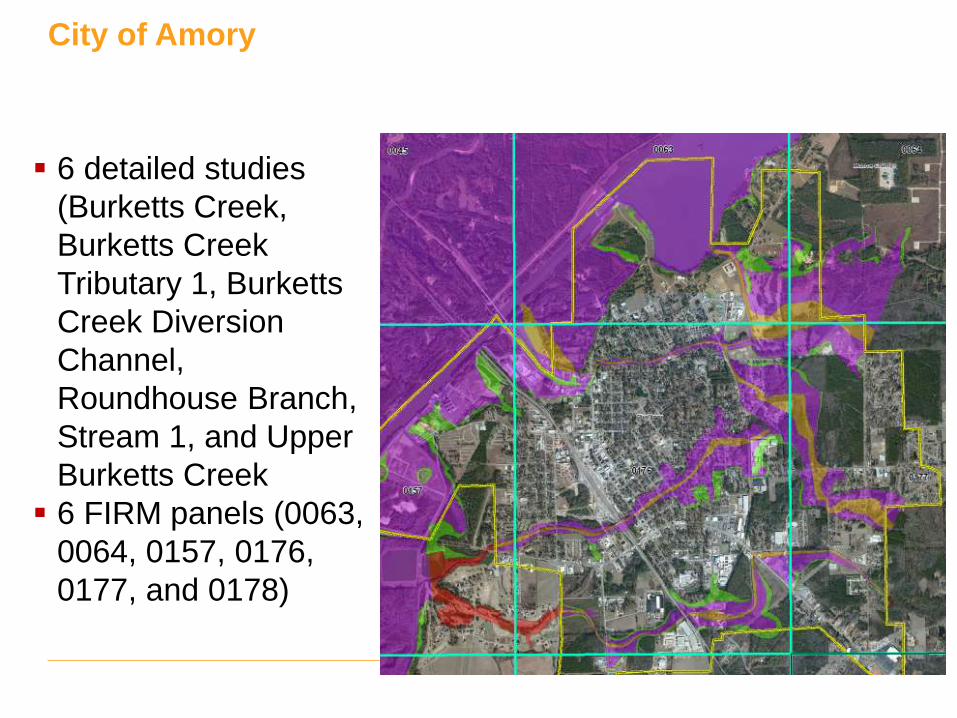
City of Amory
6 detailed studies
(Burketts Creek,
Burketts Creek
Tributary 1, Burketts
Creek Diversion
Channel,
Roundhouse Branch,
Stream 1, and Upper
Burketts Creek
6 FIRM panels (0063,
0064, 0157, 0176,
0177, and 0178)
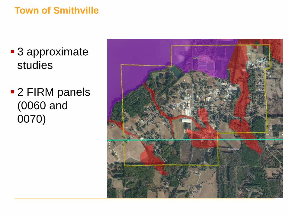
Town of Smithville
3 approximate
studies
2 FIRM panels
(0060 and
0070)
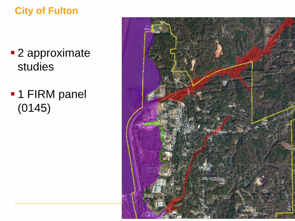
City of Fulton
2 approximate
studies
1 FIRM panel
(0145)

Where Do We Go Next?
• Pilot Study Report was accepted by FEMA
• Revised hydraulic modeling will be incorporated
• Draft work maps will be presented to the LLPT at the end of 2015
• Preliminary Flood Insurance Rate Maps for Monroe and Itawamba Counties will be issued in early 2016

Thank You
Steve Champlin, RPG
MS Dept. of Environmental Quality
P.O. Box 2279
Jackson, MS 39225
601.961.5506
Michael Taylor, PE, CFM
AECOM / MGI
1360 Peachtree St NE #500
Atlanta, GA 30309
404.946.9488
Recommended