www.artisansw.com
Slide 1
ARTiSAN Software Tools
Systems Engineering and UML (SysML)Manohar RaoGreg Narog
www.artisansw.com

www.artisansw.com
Slide 2
• Notation only • Defining the System
– Use Cases– Scenarios
• Designing the System (Object Model)– Class– Collaboration– Dynamic– Package
UML: Industry Standard Notation
www.artisansw.com
Slide 3
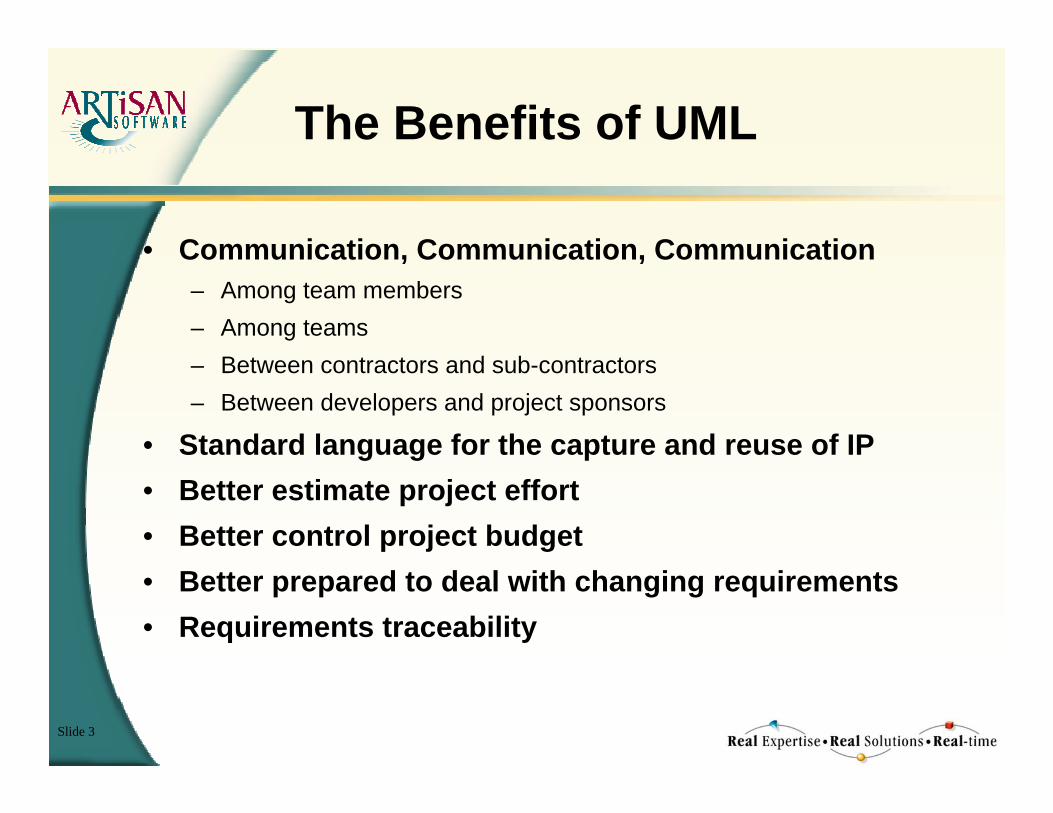
The Benefits of UML
• Communication, Communication, Communication– Among team members– Among teams– Between contractors and sub-contractors– Between developers and project sponsors
• Standard language for the capture and reuse of IP• Better estimate project effort• Better control project budget• Better prepared to deal with changing requirements• Requirements traceability

www.artisansw.com
Slide 4
The Basics of UML
Pilot
StoresNavigation Data
DeploysWeapon
PerformsSorte
Use Case Model
The Software:The SoftwarePilot Data Entry Panel
Pilot Presses Key Key PressSoftware Determines new Mode Key Press( KEY ID )if NAV Key then
Enter Navigation ModeSet Mode( NAV )
elsif Weapons Key thencase Selected Store is
when Loft Bombs => Set Mode( LOFT )when Retard Bombs => Set Mode( RETARD )when Guns => Set Mode( GUN )when Rockets => Set Mode( ROCKET )
end caseend if
Enter Navigation ModeSet Mode( NAV )
elsif Weapons Key thencase Selected Store is
when Loft Bombs => Set Mode( LOFT )when Retard Bombs => Set Mode( RETARD )when Guns => Set Mode( GUN )when Rockets => Set Mode( ROCKET )
end case
case Selected Store iswhen Loft Bombs => Set Mode( LOFT )when Retard Bombs => Set Mode( RETARD )when Guns => Set Mode( GUN )when Rockets => Set Mode( ROCKET )
end case
when Loft Bombs => Set Mode( LOFT )when Retard Bombs => Set Mode( RETARD )when Guns => Set Mode( GUN )when Rockets => Set Mode( ROCKET )
Scenario Model
::Person
NameAgeAssignUn-Assign
::Company
Name
::Contract
Start DateSalaryGradeChange Grade
::Work Instruction
DescriptionStart DateDurationPerformance RatingAgree Performance Rating
::Revenue Item
Cost
::Product ::Service
::Development Plan
Mean PerformanceTraining NeedsCurrent Skills
::Contractual Constraint
DescriptionUpdate
::Term ::Condition
11..* Works ForEmployee Employer
1..*1
Manages
Manager
Worker
1..*
1
Markets
Manufacturer
1..*1 Describes Work On
*
0..11
1
*
1
Updates
Supervisor
*1
1..*
1
Updates
1..*
1
Purchases
Customer
Item Type {Exclusive}Item Type {Exclusive}
Constraint Type {Inclusive}Constraint Type {Inclusive}
Class Model
running downEntry/monitor.inhibit(LOP);timer.set(40);motor.stop;valve[inlet].close;valve[outlet].close;valve[by-pass].open; ...
stopped
waiting for oil pressure to buildEntry/monitor.inhibit(LOP);valve[vent].close;timer.set(30);timer.set(40);motor.start; ...
waiting for gas pressure to build operating
timeup/monitor.enable(LOP)
start compressor/after( 40s )/valve[vent].open;...
after( 10s )/valve[by-pass].close;valve[inlet].open;valve[outlet].open; ...
stop compressor/
«Destroy»/
stop compressor/timer.cancel(30);timer.cancel(40);
stop compressor/timer.cancel(40);
«Create»/
[!monitor.check(LOP)]/monitor.activate(LOP)
[monitor.check(LOP)]/
Dynamic Model

www.artisansw.com
Slide 5
UML for the Complete System
DynamicDynamicPackagePackage
Collab-orationCollab-orationClassClass
ScenariosScenariosUsageUsage
ScopeScopeConstraintsConstraints
StatesStates
SystemArchitecture
SystemArchitecture
StorageStorage Database ConcurrencyConcurrency
Software Software EngineeringEngineering
SystemSystemEngineeringEngineering
Hardware Hardware EngineeringEngineering

www.artisansw.com
Slide 6
The Good News - Real-time UML
• OMG formed a working party in 1999 - the Real-time Analysis and Design Group (RTAD)– Issued Request for Proposal (RfP) for UML extensions to
support “Timeliness and Schedulability” - Adoption in mid-2001;– Two other RfP’s identified (not yet issued):
• Large-scale systems;• Quality of Service e.g. reliability, robustness (other than timeliness);
• ARTiSAN is the current chair (Alan Moore) of the submission team to address the RfP.

www.artisansw.com
Slide 7
Evolution of The UML and SysML Standards
*
OO Programming:ADAEiffelSmalltalkSimulaC++
OO Programming:OO Programming:ADAADAEiffelEiffelSmalltalkSmalltalkSimulaSimulaC++C++
Shlaer/MellorShlaer/MellorShlaer/Mellor
BoochBoochBooch
Coad/YourdonCoad/YourdonCoad/Yourdon
Wirfs-BrockWirfsWirfs--BrockBrock
Jacobson: OOSEJacobson: OOSEJacobson: OOSE
Martin/OdellMartin/OdellMartin/Odell
Rumbaugh: OMTRumbaugh: OMTRumbaugh: OMT
Bell LabsBell LabsBell Labs
XEROX PARCXEROX PARCXEROX PARC
US D.O.DUS D.O.DUS D.O.D
etc. etc.....etc. etc.....etc. etc.....
19701970’’ss 19801980’’ss 19901990’’ss
Structured Methods:SSA&DEntity ModelingEvent Modeling
Structured Methods:Structured Methods:SSA&DSSA&DEntity ModelingEntity ModelingEvent ModelingEvent Modeling
UML 1.xUMLUML 1.x1.x
19601960’’ss 20002000’’ss
SysMLSysMLSysML
INCOSEINCOSEINCOSE
UML 2.0UMLUML 2.02.0
OMGOMGOMG

www.artisansw.com
Slide 8
UML 2.0 - Main Diagrammatic Changes• New Diagrams
– Composite Structure • Component hierarchies• The Part/Port/Connector paradigm
– Interaction Overview• high-level flow of control• variant of Activity Diagram
– Timing• change in state over time (linear)
• Significant changes to other diagrams– Sequence Diagrams
• More structure to interactions• Sequence diagram hierarchies
– Activity Diagrams• Divorced from state diagrams• Additional notations

www.artisansw.com
Slide 9
UML for Systems Engineers ?
• UML is already de facto standard within software engineering community– simplify handover– minimize errors
• UML is mature and extensible, and can be adapted to support SE requirements– SysML profile
• UML tools and training are widely available• OMG standardization process supports UML customization for specific domains (e.g., systems engineering)

www.artisansw.com
Slide 10
Modeling Requirements for Systems Engineers
• Structure– e.g., system hierarchy, interconnection, decomposition
• Behavior– e.g., function-based behavior, state-based behavior,
decomposition of behavior• Properties
– e.g., parametric models, time property• Requirements
– e.g., requirements hierarchy, traceability, relationships• Verification/Validation
– e.g., test cases, verification/validation results• Other
– e.g., trade-off studies, spatial relationships

www.artisansw.com
Slide 11
Key SysML Extensions
• Additional Diagrams– Assembly Diagram– Requirements Diagram– Parametric Diagram
• Extensions to some UML diagrams– Activity Diagram– Structure Diagram– Class Diagram
• Other– Item Flows– Quantities Model

www.artisansw.com
Slide 12
SysML Assembly Diagram Vehicle
«assembly» : Power Train
«assembly» : Engine
«assembly» : Transmission
«assembly» : Transaxle
«assembly» 4
: Wheel «assembly»brake : Brakes
«assembly»: Steering
«assembly» control :VehicleController
sensors : Sensor
«assembly» : Suspension
«assembly» b&c : Body & Chassis
CANBus
: Exhaust System
clutch
driveshaft
halfshaft
Wiring
Hub
Rack
Struts
Socket

www.artisansw.com
Slide 13
SysML Requirements Diagram
« re q u ire m e n t» V e h ic le S ys te m S p e c ific a tio n
« re q u ire m e n t»{id # = 1 0 2 }
{tx t= S ys te m sh a ll ...{c ritica lity = H }
R 1 0 2
« re q u ire m e n t»{id # = 1 1 1 }
{tx t= S ys te m sh ...{c rit ic a lity = L }
R 1 1 1 ...
« re q u ire m e n t» P o w e r S u b sys te m S p e c ifica tio n
« re q u ire m e n t»{id # = 3 3 7 }
{tx t = T h e su b sys te ...{c ritica lity = H }
R 3 3 7
« re q u ire m e n t»{id # = 3 4 0 }
{tx t = T h e su b sys te ...{c rit ic a lity = M }
R 3 4 0
« re q u ire m e n t»R 3 3 7 .1 « re q u ire m e n t»
R 3 3 7 .2 « te s tC a se »E n g in e H o rse p o w e r T e s t
V e h ic le S ys te m D e s ig n
« s ys te m »V e h ic le
« a sse m b ly»P o w e r T ra in
« a sse m b ly»B ra k e s
P o w e r S u b sys te m D e s ig n (A lte rn a tive = V 6 )
« re q u ire m e n t»U se C a se M o d e l
« d o cu m e n t» M a rk e tN e e d s
1
1
1
1b ra k e
« sa tis fy»
« tra c e »
« tra ce »
« ve rify»
« sa tis fy»
« tra c e »
«ra tio n a le»R e f: S ta te m e n t o f W o rk
« d ia g ra m D e s c rip tio n»ve rs io n = ”0 .1 "d e s c rip tio n = ”D e p ic ts flo w d o w n o f a cce le ra tio n re q t"re fe re n ce = ”R e q u ire m e n ts M a n a g e m e n t D a ta b a se ”co m p le te n e s s= ”p a rtia l”
S ys te m sh a ll a cce le ra te fro m 0 - 6 0 m p h in le s t th a n 8 se co n d s u n d e r th e s p e c ifie d co n d itio n s
re q :V e h ic le S ys te m R e q tsF lo w D o w n

www.artisansw.com
Slide 14
SysML ParametricsDiagram
Road.incline «paramConstraint»
{F=weight*sin(theta)}: GravitationalForce Vehicle.weight
Vehicle.dragForce
Vehicle.dragCoef
Vehicle.acceleration
Vehicle.speed
Engine.displacement
«paramConstraint»: TotalForce
Vehicle.powertrainForce
«paramConstraint»: Power Train Equations
«paramConstraint» {Force =
0.5*dragCoef*rho*speed^2}: DragForce
«paramConstraint»: Integration
dv/dt
v
«paramConstraint» {f=m*a}
: Newton's Law
f
m
a
par:VehiclePerformance

www.artisansw.com
Slide 15
The ARTiSAN Approach: System Definition
Power Up
initialisation completed/
power down/
start price update sequence/
price verification completed/
System Initialisation
System Operational
Updating Fuel Prices
UsageConstraints Modes
KioskOperator
Filling StationManager
EPOS
Customeruses
uses
uses
usesextends
Scope
EPOS
KioskOperator
Manager
Filling Station SystemDispenser
EH Unit
Dispenser Display
EH Unit
Fast Flow Valve
Fast Flow Valve
Motor
Flow meter
Holster Switch
Kiosk Controller I/O
Keyboard Unit
Kiosk Display
transaction details()
replace nozzle()
remove nozzle()
display check sequence()
transaction details()
Customer
Power-on
Fuel Transaction
Sales Transaction
Configure Dispensers
Start Dispensing
StopDispensing
Set DispenserFuel Prices
Suspend Dispensing
Reliability
MTBF MTTR
Max. Flow Rate
Flow Sample
resolution
Display Volume
Resolution
Performance
System Software

www.artisansw.com
Slide 16
The ARTiSAN Approach: System Design
Physicalarchitecture
Infrastructure Multi-tasking persistence
Application interface control entity

www.artisansw.com
Slide 17
The Software:The SoftwarePilot Data Entry Panel
Pilot Presses Key Key PressSoftware Determines new Mode Key Press( KEY ID )if NAV Key then
Enter Navigation ModeSet Mode( NAV )
elsif Weapons Key thencase Selected Store is
when Loft Bombs => Set Mode( LOFT )when Retard Bombs => Set Mode( RETARD )when Guns => Set Mode( GUN )when Rockets => Set Mode( ROCKET )
end caseend if
Enter Navigation ModeSet Mode( NAV )
elsif Weapons Key thencase Selected Store is
when Loft Bombs => Set Mode( LOFT )when Retard Bombs => Set Mode( RETARD )when Guns => Set Mode( GUN )when Rockets => Set Mode( ROCKET )
end case
case Selected Store iswhen Loft Bombs => Set Mode( LOFT )when Retard Bombs => Set Mode( RETARD )when Guns => Set Mode( GUN )when Rockets => Set Mode( ROCKET )
end case
when Loft Bombs => Set Mode( LOFT )when Retard Bombs => Set Mode( RETARD )when Guns => Set Mode( GUN )when Rockets => Set Mode( ROCKET )
The Software:The SoftwarePilot Data Entry Panel
Pilot Presses Key Key PressSoftware Determines new Mode Key Press( KEY ID )if NAV Key then
Enter Navigation ModeSet Mode( NAV )elsif Weapons Key then
case Selected Store iswhen Loft Bombs => Set Mode( LOFT )when Retard Bombs => Set Mode( RETARD )when Guns => Set Mode( GUN )when Rockets => Set Mode( ROCKET )
end caseend if
Enter Navigation ModeSet Mode( NAV )elsif Weapons Key then
case Selected Store iswhen Loft Bombs => Set Mode( LOFT )when Retard Bombs => Set Mode( RETARD )when Guns => Set Mode( GUN )when Rockets => Set Mode( ROCKET )
end case
case Selected Store iswhen Loft Bombs => Set Mode( LOFT )when Retard Bombs => Set Mode( RETARD )when Guns => Set Mode( GUN )when Rockets => Set Mode( ROCKET )
end case
when Loft Bombs => Set Mode( LOFT )when Retard Bombs => Set Mode( RETARD )when Guns => Set Mode( GUN )when Rockets => Set Mode( ROCKET )
The Software:The SoftwarePilot Data Entry Panel
Pilot Presses Key Key PressSoftware Determines new Mode Key Press( KEY ID )if NAV Key then
Enter Navigation ModeSet Mode( NAV )
elsif Weapons Key thencase Selected Store is
when Loft Bombs => Set Mode( LOFT )when Retard Bombs => Set Mode( RETARD )when Guns => Set Mode( GUN )when Rockets => Set Mode( ROCKET )
end caseend if
Enter Navigation ModeSet Mode( NAV )
elsif Weapons Key thencase Selected Store is
when Loft Bombs => Set Mode( LOFT )when Retard Bombs => Set Mode( RETARD )when Guns => Set Mode( GUN )when Rockets => Set Mode( ROCKET )
end case
case Selected Store iswhen Loft Bombs => Set Mode( LOFT )when Retard Bombs => Set Mode( RETARD )when Guns => Set Mode( GUN )when Rockets => Set Mode( ROCKET )
end case
when Loft Bombs => Set Mode( LOFT )when Retard Bombs => Set Mode( RETARD )when Guns => Set Mode( GUN )when Rockets => Set Mode( ROCKET )
Scenario Model
running downEntry/monitor.inhibit(LOP);timer.set(40);motor.stop;valve[inlet].close;valve[outlet].close;valve[by-pass].open; ...
stopped
waiting for oil pressure to buildEntry/monitor.inhibit(LOP);valve[vent].close;timer.set(30);timer.set(40);motor.start; ...
waiting for gas pressure to build operating
timeup/monitor.enable(LOP)
start compressor/after( 40s )/valve[vent].open;...
after( 10s )/valve[by-pass].close;valve[inlet].open;valve[outlet].open; ...
stop compressor/
«Destroy»/
stop compressor/timer.cancel(30);timer.cancel(40);
stop compressor/timer.cancel(40);
«Create»/
[!monitor.check(LOP)]/monitor.activate(LOP)
[monitor.check(LOP)]/
Dynamic Model
::Person
NameAgeAssignUn-Assign
::Company
Name
::Contract
Start DateSalaryGradeChange Grade
::Work Instruction
DescriptionStart DateDurationPerformance RatingAgree Performance Rating
::Revenue Item
Cost
::Product ::Service
::Development Plan
Mean PerformanceTraining NeedsCurrent Skills
::Contractual Constraint
DescriptionUpdate
::Term ::Condition
11..* Works ForEmployee Employer
1..*1
Manages
Manager
Worker
1..*
1
Markets
Manufacturer
1..*1 Describes Work On
*
0..11
1
*
1
Updates
Supervisor
*1
1..*
1
Updates
1..*
1
Purchases
Customer
Item Type {Exclusive}Item Type {Exclusive}
Constraint Type {Inclusive}Constraint Type {Inclusive}
Class Model
OperationalParameters Performance
Loader Speed
Belt Speed
Containers ScanSuccess
DefectiveContainers Accuracy
Non-Functional Constraints
Take-off Valve
RemoteOperator
Local operator
Nitrogen Compression Plant
NCP System
HP Tank
HPT Switch HP Switch LPT SwitchLP Switch
Remote Monitoring Unit
Local Indication Panel
Compressor Unit
CompressorMotor
CompressorSensors
Valves
By-pass ValveVent ValveInlet Valve Outlet Valve
NCP System
HP Tank
HPT Switch HP Switch LPT SwitchLP SwitchHPT Switch HP Switch LPT SwitchLP Switch
Remote Monitoring Unit
Local Indication Panel
Compressor Unit
CompressorMotor
CompressorSensors
CompressorMotor
CompressorSensors
Valves
By-pass ValveVent ValveInlet Valve Outlet Valve By-pass ValveVent ValveInlet Valve Outlet Valve
open()open() close()close()
250 bar()250 bar()
reset()
alarm()
reset()
alarm()
reset()
alarm()
reset()
alarm()
system stop()system stop()
alarm()
reset()
alarm()
reset()
150 bar()150 bar()
system start()
system stop()
system start()
system stop()
stop()
start()
stop()
start()
Context DiagramRemote Monitoring Unit
RMU Display Stop ButtonRMU Display Stop Button
Local Indication Panel
stop/startbuttons
LIP Display stop/startbuttons
LIP Display
Plant Controller
system bus
display board
serial i/f
I/O board
motherboard
remote comms.
serial i/f
system bus
display board
serial i/fserial i/f
I/O board
motherboard
remote comms.
serial i/fserial i/f
Compressor Unit
CompressorMotor
Low OilPressure switch
Inlet Gas PressureTrip Switch
Outlet GasPressure Trip
Switch
Coolant FlowMeter
CompressorMotor
Low OilPressure switch
Inlet Gas PressureTrip Switch
Outlet GasPressure Trip
Switch
Coolant FlowMeter
HP Tank
HPT Switch
HP Switch
LPT Switch
LP Switch
HPT Switch
HP Switch
LPT Switch
LP Switch
Outlet Valve Vent ValveBy-pass ValveInlet Valve
3 wire RS2323 wire RS232
RS422RS422 All I/O board connections are 24V DC single phase. Valve connections are in fact 2 single 1-way connections rather one 2-way ...
Hardware Architecture
Start/Stop Requests
Alarms Status
Timeout Events
Alarm Inhibits /Enables
Alarm MonitoringTask (AMT)
Display andCommunication
Task (DCT)
Timer Task(TT)
CompressorController Task
(CCT)
Timer Requests
alarm status data
Plant Status
Real WorldTrips
Real WorldDevices
Networks ( forLIP and RMU)
Set() Clear()Set() Clear()
Read()Read()
Set()Set()
Check()Check()
Post()Post()
Write()Write()
Read()Read()
Set()Set()
Read()
Clear()
Read()
Clear()
Write()Write()
Read()Read()
Write()Write()
Read()Read() Read()
Clear()
Read()
Clear()
Concurrency ModelSourceFiles
Putting it All Together:UML for the Whole System
Requirements
Pilot
StoresNavigation Data
DeploysWeapon
PerformsSorte
Use Case Model
Starting Up System
Fail Safe
Shutting Down System
Compressor Off
Compressor On
State4
Compressor Off
Compressor On
after( 40s )/
system start/Start Up Plant
power down/
system stop/Shutdown Plant
alarm/Handle Alarm
after( 180s )/Maintain Gas Pressurealarm/Handle Alarm
power up/
[LPT and LOP alarms ringing]/
[els e]/
[els e]/
250 bar/Stop Compressor
150 bar/Start Compressor
[LOP alarm ringing]/
Modes Diagram

www.artisansw.com
Slide 18
Questions, Comments, Discussion
*
Recommended