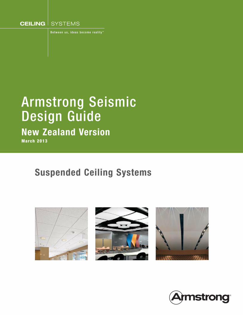
Armstrong Seismic Design Guidenew Zealand VersionMarch 2013
Suspended Ceiling Systems
Ceiling SyStemS
B e t w e e n u s , i d e a s b e c o m e r e a l i t y ™

Suspended Ceiling - Seismic Design
All structures and parts of structures including suspended ceilings shall be designed to resist earthquake
actions as set out in NZS 1170.5. In previous earthquakes throughout history, suspended ceilings have
shown a tendency to perform poorly. This may be due to the fact that they are often overlooked and the
code requirements for seismic design are low. It is important that suspended ceilings are designed suitably
to ensure they perform in a seismic event. The failure of suspended ceilings can cause evacuation paths to
be blocked which could be a hazard to life safety. Failure can also cause unnecessary delays in resuming
business especially if the rest of the structure has sustained no damage.
The purpose of this guide is to provide a method for the seismic design of suspended grid and tile ceiling
systems. It has been designed to meet the requirements of NZS 1170.5 – Structural Design Actions –
Earthquake actions. From this guide, a grid type, bracing requirements and fixing types can be designed.
Please note that this guide is not suitable for all suspended ceilings and those which fall outside its’ scope
must be designed by a suitably qualified structural engineer.
1
table of Contents
Suspended Ceiling - Seismic Design 2
Table of Contents 3
Design Statement 3
Limitations and Assumptions 4
Design Considerations 4
How to Use This Document 5
Bracing Layout Options 6
Perimeter Fixing 6
Back Bracing 6
Seismic Loading 8
Bracing Option Layouts 1 & 2 (Perimeter Fixing) 9
Perimeter Connection Details 10
Bracing Layout Option 3 (Back Bracing) 11
Installation of Bracing 12
Summary Sheet 14
Seismic Gap Options and other Armstrong Details 15
List of seismic factors for specific towns/cities. 17
Design Statement
Knowles Consulting Limited (KCL) has been engaged by Forman Building Systems to provide a suspended
ceiling seismic design guide which is accurate and easy to follow. The guide has been prepared to meet the
requirements of the NZ building code
Testing of the grids was undertaken to determine the compression and tension capacities. Testing of the
perimeter fixings was also undertaken. The values from this testing have been used in this guide.
2
Limitations and assumptions
LimitationS ■ This guide may only be used to design suspended ceilings with Armstrong Prelude XL and Suprafine
XL ceiling grids.
■ This guide may only be used for buildings in New Zealand.
■ The ceiling system must meet both gravity and seismic load requirements.
■ All other Forman & Armstrong brochures, manuals and codes must be adhered to.
■ All individual objects weighing over 10kg shall be braced separately unless specifically designed by a
structural engineer. Similarly ceiling tile must weigh less than 10kg each unless a structural engineer
is consulted.
■ The perimeter shall be nogged continuously at ceiling level if ceiling is fixed at perimeter. This is to
ensure that the loads can be transferred from the ceiling into the perimeter support. If the perimeter
is not continuously nogged, the perimeter fixing option may NOT be used.
■ A structural engineer for the building must check all lateral loads can be resisted by the support
structure. The support structure must be both strong enough and stiff enough.
■ Ceiling grid tees must be spaced at a maximum of 1.2m centres.
■ Partition walls must not be braced by the ceiling grid unless designed by a qualified structural
engineer.
■ The ceiling must not be a structural component of the building. It may not be used to transfer loads
between structural elements of the building.
■ For a Level 4 importance building (e.g. hospital or police station) a qualified structural engineer must
be consulted.
■ For ceilings with a plenum of less than 300mm back bracing cannot be used without consulting a
qualified structural engineer.
aSSumptionS ■ The period of the ceiling is assumed to be T≤0.75s
■ Assume ceiling grid ductility µ=1.0
3
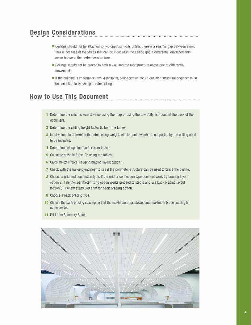
Design Considerations
■ Ceilings should not be attached to two opposite walls unless there is a seismic gap between them.
This is because of the forces that can be induced in the ceiling grid if differential displacements
occur between the perimeter structures.
■ Ceilings should not be braced to both a wall and the roof/structure above due to differential
movement.
■ If the building is importance level 4 (hospital, police station etc.) a qualified structural engineer must
be consulted in the design of the ceiling.
How to use this Document
1 Determine the seismic zone Z value using the map or using the town/city list found at the back of the
document.
2 Determine the ceiling height factor H, from the tables.
3 Input values to determine the total ceiling weight. All elements which are supported by the ceiling need
to be included.
4 Determine ceiling slope factor from tables.
5 Calculate seismic force, Fp using the tables.
6 Calculate total force, Ft using bracing layout option 1.
7 Check with the building engineer to see if the perimeter structure can be used to brace the ceiling.
8 Choose a grid and connection type. If the grid or connection type does not work try bracing layout
option 2. If neither perimeter fixing option works proceed to step 8 and use back bracing layout
(option 3). Follow steps 8-9 only for back bracing option.
9 Choose a back bracing type.
10 Choose the back bracing spacing so that the maximum area allowed and maximum brace spacing is not exceeded.
11 Fill in the Summary Sheet.
4
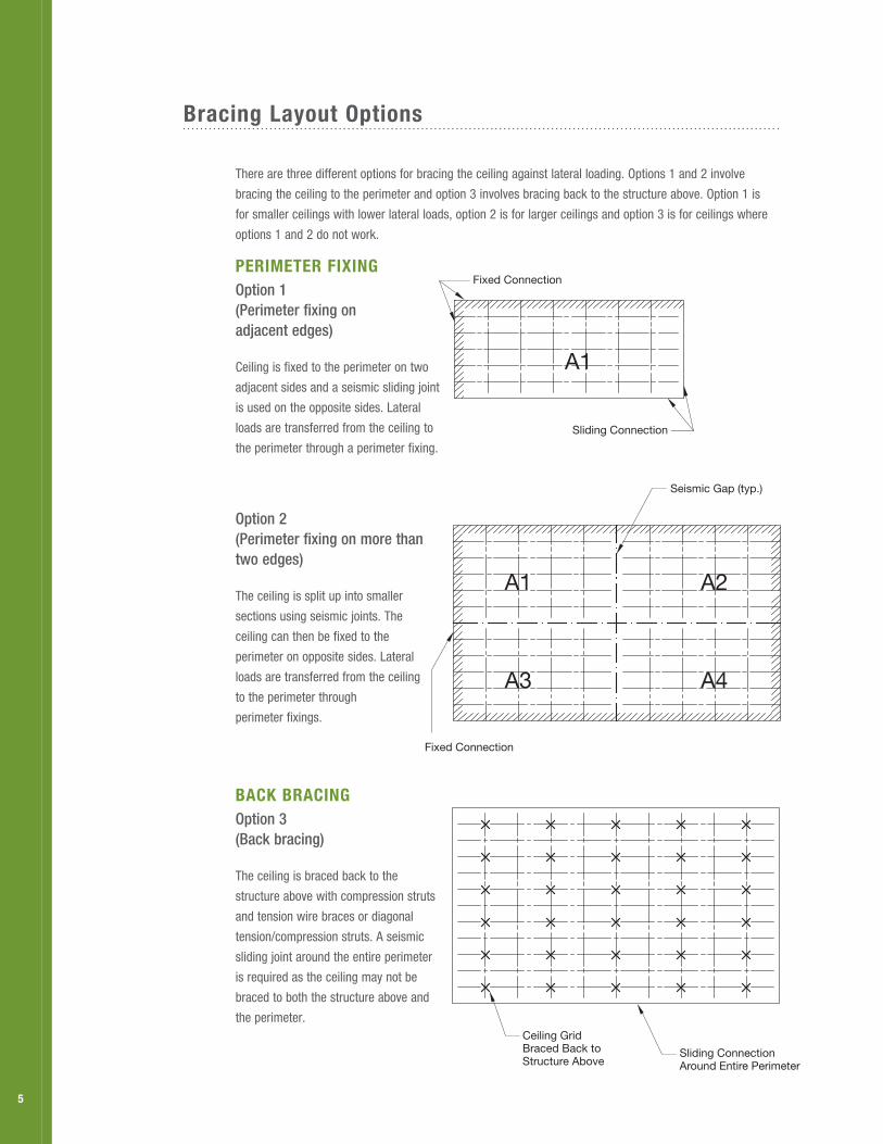
Bracing Layout options
There are three different options for bracing the ceiling against lateral loading. Options 1 and 2 involve
bracing the ceiling to the perimeter and option 3 involves bracing back to the structure above. Option 1 is
for smaller ceilings with lower lateral loads, option 2 is for larger ceilings and option 3 is for ceilings where
options 1 and 2 do not work.
perimeter fixingOption 1 (Perimeter fixing on adjacent edges)
Ceiling is fixed to the perimeter on two
adjacent sides and a seismic sliding joint
is used on the opposite sides. Lateral
loads are transferred from the ceiling to
the perimeter through a perimeter fixing.
Option 2 (Perimeter fixing on more than two edges)
The ceiling is split up into smaller
sections using seismic joints. The
ceiling can then be fixed to the
perimeter on opposite sides. Lateral
loads are transferred from the ceiling
to the perimeter through
perimeter fixings.
BaCk BraCingOption 3 (Back bracing)
The ceiling is braced back to the
structure above with compression struts
and tension wire braces or diagonal
tension/compression struts. A seismic
sliding joint around the entire perimeter
is required as the ceiling may not be
braced to both the structure above and
the perimeter.
Fixed Connection
Sliding Connection
Fixed Connection
Seismic Gap (typ.)
Ceiling Grid Braced Back toStructure Above
Sliding Connection Around Entire Perimeter
A1A1
A3
A2
A4
Fixed Connection
Sliding Connection
Fixed Connection
Seismic Gap (typ.)
Ceiling Grid Braced Back toStructure Above
Sliding Connection Around Entire Perimeter
A1A1
A3
A2
A4
Fixed Connection
Sliding Connection
Fixed Connection
Seismic Gap (typ.)
Ceiling Grid Braced Back toStructure Above
Sliding Connection Around Entire Perimeter
A1A1
A3
A2
A4
5
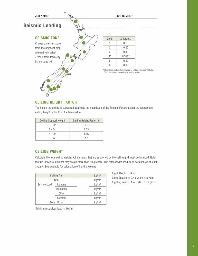
Seismic Loading
SeiSmiC ZoneChoose a seismic zone
from the adjacent map.
Alternatively select
Z Value from town/city
list on page 16
CeiLing HeigHt faCtorThe height the ceiling is supported at affects the magnitude of the Seismic Forces. Select the appropriate
ceiling height factor from the table below.
CeiLing WeigHtCalculate the total ceiling weight. All elements that are supported by the ceiling grid must be included. Note
that no individual element may weigh more than 10kg each. The total service load must be taken as at least
3kg/m². See example for calculation of lighting weight.
Light Weight = 4 kg
Light Spacing = 2.4 x 2.4m = 5.76m2
Lighting Load = 4 ÷ 5.76 = 0.7 kg/m2
*Minimum services load is 3kg/m²
Fixed Connection
Sliding Connection
Fixed Connection
Seismic Gap (typ.)
Ceiling Grid Braced Back toStructure Above
Sliding Connection Around Entire Perimeter
A1A1
A3
A2
A4
Job Name: Job Number:
Zone Z Value <
1 0.13
2 0.20
3 0.30
4* 0.396*
5 0.50
6 0.60
* Christchurch earthquake zone requires a higher return period factor. The Z value has been modified to account for this.
Ceiling Support Height Ceiling Height Factor, H
0 - 3m 1.0
3 - 6m 1.33
6 - 9m 1.66
> 9m 2.0
Ceiling Tile kg/m²
Grid kg/m²
Service Load* Lighting kg/m²
Insulation kg/m²
Other kg/m²
Subtotal kg/m²
Total Wp = kg/m²
6
Su
Sp
enD
eD C
eiLing
SeiS
miC
DeS
ign
for
m
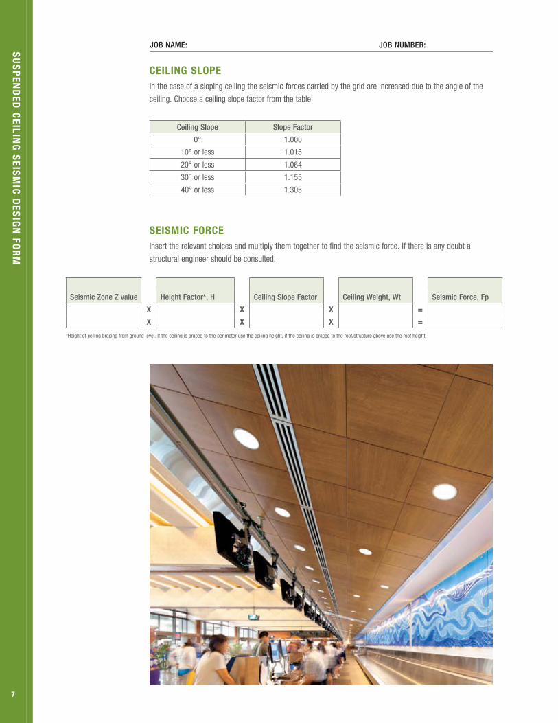
CeiLing SLopeIn the case of a sloping ceiling the seismic forces carried by the grid are increased due to the angle of the
ceiling. Choose a ceiling slope factor from the table.
SeiSmiC forCeInsert the relevant choices and multiply them together to find the seismic force. If there is any doubt a
structural engineer should be consulted.
Job Name: Job Number:
Seismic Zone Z value Height Factor*, H Ceiling Slope Factor Ceiling Weight, Wt Seismic Force, Fp
x x x =
x x x =
*Height of ceiling bracing from ground level. If the ceiling is braced to the perimeter use the ceiling height, if the ceiling is braced to the roof/structure above use the roof height.
Ceiling Slope Slope Factor
0° 1.000
10° or less 1.015
20° or less 1.064
30° or less 1.155
40° or less 1.305
7
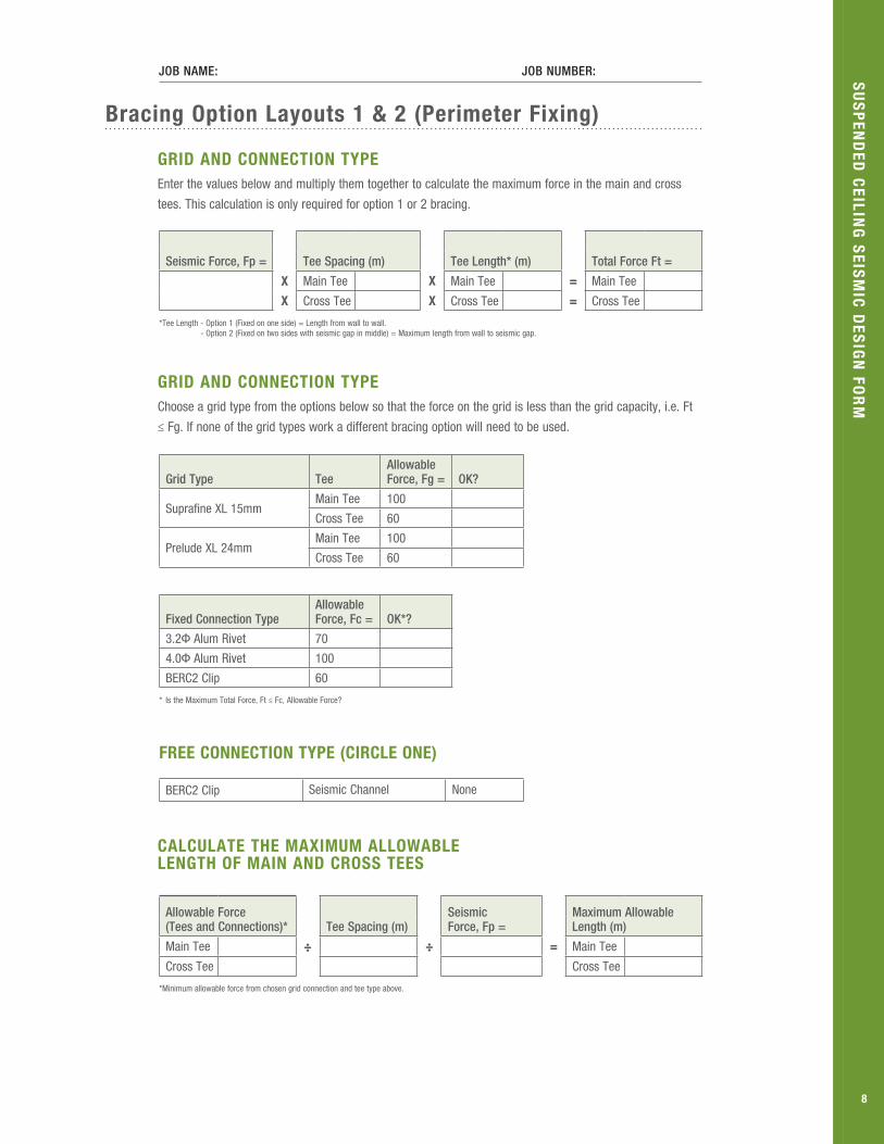
Bracing option Layouts 1 & 2 (perimeter fixing)
griD anD ConneCtion typeEnter the values below and multiply them together to calculate the maximum force in the main and cross
tees. This calculation is only required for option 1 or 2 bracing.
griD anD ConneCtion typeChoose a grid type from the options below so that the force on the grid is less than the grid capacity, i.e. Ft
≤ Fg. If none of the grid types work a different bracing option will need to be used.
Seismic Force, Fp = Tee Spacing (m) Tee Length* (m) Total Force Ft =
x Main Tee x Main Tee = Main Tee
x Cross Tee x Cross Tee = Cross Tee
* Tee Length - Option 1 (Fixed on one side) = Length from wall to wall. - Option 2 (Fixed on two sides with seismic gap in middle) = Maximum length from wall to seismic gap.
Grid Type TeeAllowable Force, Fg = OK?
Suprafine XL 15mmMain Tee 100
Cross Tee 60
Prelude XL 24mmMain Tee 100
Cross Tee 60
Fixed Connection TypeAllowable Force, Fc = OK*?
3.2Φ Alum Rivet 70
4.0Φ Alum Rivet 100
BERC2 Clip 60
* Is the Maximum Total Force, Ft ≤ Fc, Allowable Force?
Job Name: Job Number:
CaLCuLate tHe maximum aLLoWaBLe LengtH of main anD CroSS teeS
Allowable Force (Tees and Connections)* Tee Spacing (m)
Seismic Force, Fp =
Maximum Allowable Length (m)
Main Tee ÷ ÷ = Main Tee
Cross Tee Cross Tee
* Minimum allowable force from chosen grid connection and tee type above.
Su
Sp
enD
eD C
eiLing
SeiS
miC
DeS
ign
for
m
free ConneCtion type (CirCLe one)
BERC2 Clip Seismic Channel None
8

Job Name: Job Number:
perimeter Connection Details
fixeD ConneCtionIt is very important that the grid is fixed to the perimeter properly so that the loads can be transferred
from the ceiling into the building structure. The following criteria must be followed when attaching to the
perimeter:
■ The wall angle must be fixed to the building structure within 20mm of the grid fixing.
■ The wall angle must be fixed at 600mm centres minimum. See table below for fixing type.
■ When using BERC2 clips for fixing option ensure it is screwed to BOTH the wall angle and tee.
■ Required edge distances must be followed when fixing rivets.
■ Ensure building perimeter structure has been reviewed by the building engineer to check that it can
resist lateral loads.
SLiDing ConneCtionIt is important that the sliding connection is built properly so that additional loads are not experienced by
the grid.
■ The BERC2 Clip must be screwed to the wall angle. The screw connecting the grid and clip must not
be tightened and placed centrally in the sliding slot.
■ The end of the grid must be located 19mm away from the wall angle.
■ When using a seismic channel a hanger must be placed within 200mm of the perimeter.
WaLL angLe perimeter fixing type
Perimeter Material Fixing Type*
Timber No. 8 x 51mm screw
Steel 14G Tek screw
Concrete Ramset 6x30mm Dynabolt or equivalent
* The fixing types in the table above may be exchanged for an alternative fixing with a safe working strength of greater than 1.5kN that is suitable for seismic loading. (e.g. Concrete Screw Anchors are not suitable for seismic loadings)
Su
Sp
enD
eD C
eiLing
SeiS
miC
DeS
ign
for
m
9

Job Name: Job Number:
Bracing Layout option 3 (Back Bracing)
This section is to be used only for bracing option 3 where the grid is braced back to the structure above.
This option is required when the forces in the grid are too high to allow perimeter fixing. Choose a brace
type from the options below and calculate the maximum ceiling area allowed per brace. Any Armstrong grid
may be used as the back-bracing strengths govern the design.
BraCing typeBrace A – Rondo 64x0.50 BMT Stud Strut with 4/2.5 dia wire diagonals.
Brace B – Rondo 64x0.50 BMT Strut with 2/64x0.50 BMT Stud diagonals.
Brace C – Rondo 92x0.75 BMT Strut with 2/92x0.75 BMT Stud diagonals.
maximum area per BraCeCalculate the maximum ceiling area allowed per brace for a chosen brace and plenum height. If the max
area per brace is too small a stronger bracing type may need to be chosen.
area per BraCeChoose the spacing of braces and multiply the numbers together to get the area of ceiling per brace. At least
every second main tee should be braced to avoid the ceiling having to perform as a diaphragm. The area per
brace must be less than the maximum area calculated above. The spacing of the braces in both directions
is governed by the spacing of tees and also the spacing of structural elements in the roof above (i.e. purlin
spacing). If the spacing of braces seems too close use a stronger brace.
BraCe fixing typeSThe table below gives the minimum connection for the different bracing types.
Plenum Depth (m) Brace A Brace B Brace C
0-0.6 90 250 300 Seismic Force, Fp =
Max Area Per Brace (m²)0.6-1.0 90 250 300
1.0-1.4 90 250 300 ÷ =
1.4-1.8 90 160 300
1.8-2.4 90 90 170
Brace Spacing Along Main Tee
Brace Spacing Along Cross Tee*
Area Per Brace (m²) OK?
Area = x =
* Braces should be spaced a maximum of every second main tee (typically 2.4m) and a maximum of 12m along the main tees.
Brace A Brace B Brace C
Steel 2x 14G Tek Screw 4x 14G Tek Screw 4x 14G Tek Screw
Concrete 2x M6x30 Dynabolt 2x M6x30 Dynabolt 2x M6x30 Dynabolt
Timber 2x No 8x51 screw 4x No 8x51 screw 4x No 8x51 screw
Grid Tee 2x14G Tek screw 3x14G Tek screw 3x14G Tek screw
Su
Sp
enD
eD C
eiLing
SeiS
miC
DeS
ign
for
m
10
Job Name: Job Number:
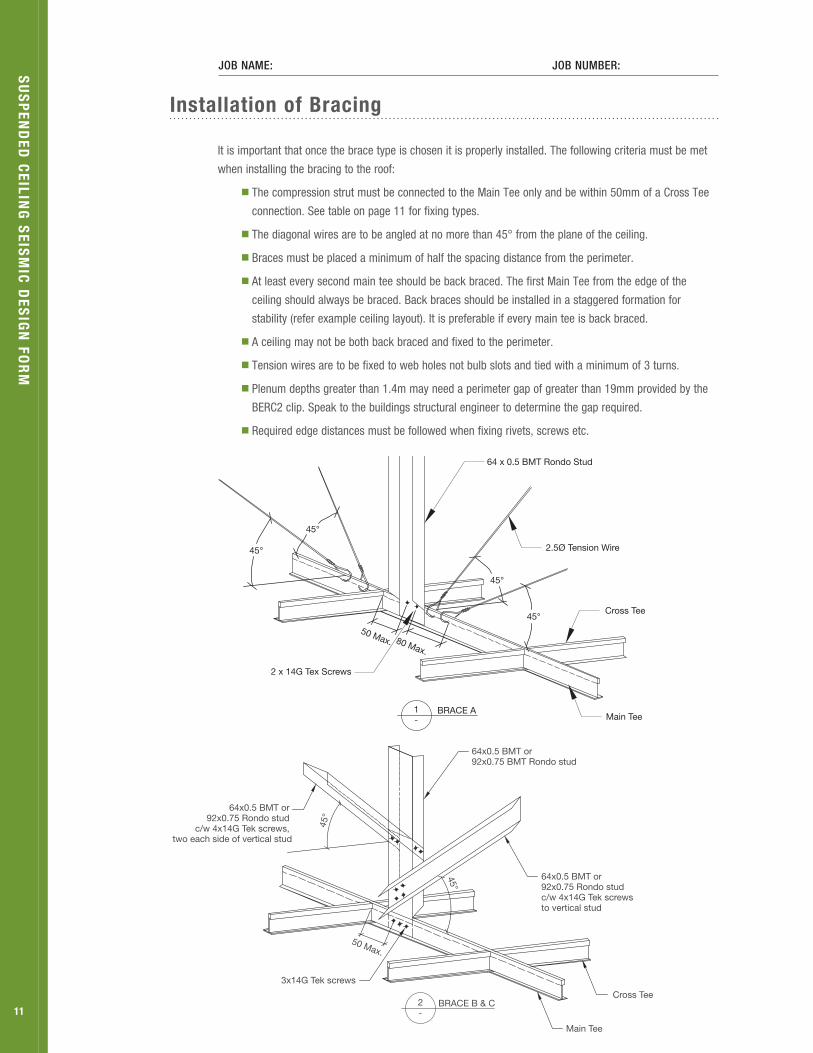
installation of Bracing
It is important that once the brace type is chosen it is properly installed. The following criteria must be met
when installing the bracing to the roof:
■ The compression strut must be connected to the Main Tee only and be within 50mm of a Cross Tee
connection. See table on page 11 for fixing types.
■ The diagonal wires are to be angled at no more than 45° from the plane of the ceiling.
■ Braces must be placed a minimum of half the spacing distance from the perimeter.
■ At least every second main tee should be back braced. The first Main Tee from the edge of the
ceiling should always be braced. Back braces should be installed in a staggered formation for
stability (refer example ceiling layout). It is preferable if every main tee is back braced.
■ A ceiling may not be both back braced and fixed to the perimeter.
■ Tension wires are to be fixed to web holes not bulb slots and tied with a minimum of 3 turns.
■ Plenum depths greater than 1.4m may need a perimeter gap of greater than 19mm provided by the
BERC2 clip. Speak to the buildings structural engineer to determine the gap required.
■ Required edge distances must be followed when fixing rivets, screws etc.
Su
Sp
enD
eD C
eiLing
SeiS
miC
DeS
ign
for
m
64 x 0.5 BMT Rondo Stud
50 Max.
45°
45°
2 x 14G Tex Screws
BRACE A1-
80 Max.
2.5Ø Tension Wire
45°
45°
Main Tee
Cross Tee
11BRACE B & C2
-
64x0.5 BMT or 92x0.75 BMT Rondo stud
Main Tee
Cross Tee
45°
50 Max.
45°
64x0.5 BMT or 92x0.75 Rondo stud
c/w 4x14G Tek screws, two each side of vertical stud
64x0.5 BMT or 92x0.75 Rondo stud c/w 4x14G Tek screws to vertical stud
3x14G Tek screws

Summary Sheet
JOB NAMe: JOB NuMBeR:
SiTe LOCATiON:
CeiLiNG LeVeL:
Fill out the Summary sheet below from the types chosen in the preceding sheets.
griD type
Main Tee Suprafine XL 15mm
Prelude XL 24mm
@ m centres. Max Length =
m
Cross Tee Suprafine XL 15mm
Prelude XL 24mm
@ m centres. Max Length =
m
SeiSmiC gap (CirCLe one)
Seismic Joint Clip SJMR15 24mm grid
Seismic Joint Clip SJMR9 15mm grid
None
BaCk BraCing type (BraCing Layout option 3 onLy)
Plenum Depth:
Brace Spacing: Between Main Tees m
Between Cross Tees m
Brace Type (circle one) Bracing Description Fixing to Structure Above (see fixing type table)
Fixing to Tee (see fixing type table)
Brace A Rondo 64x0.50 BMT Stud Strut with 2.5 dia wire diagonals.
Brace B Rondo 64x0.50 BMT Strut with 2/64x0.50 BMT Stud diagonals.
Brace C Rondo 92x0.75 BMT Strut with 2/92x0.75 BMT Stud diagonals.
markup pLan attaCHeD? (CirCLe one)
Yes No
perimeter fixingFixed Connection 3.2Φ Rivet 4.0Φ Rivet BERC2 Clip
Free Connection BERC2 Clip Sliding Joint (Hanger ≤ 200mm)
Su
Sp
enD
eD C
eiLing
SeiS
miC
DeS
ign
for
m
12
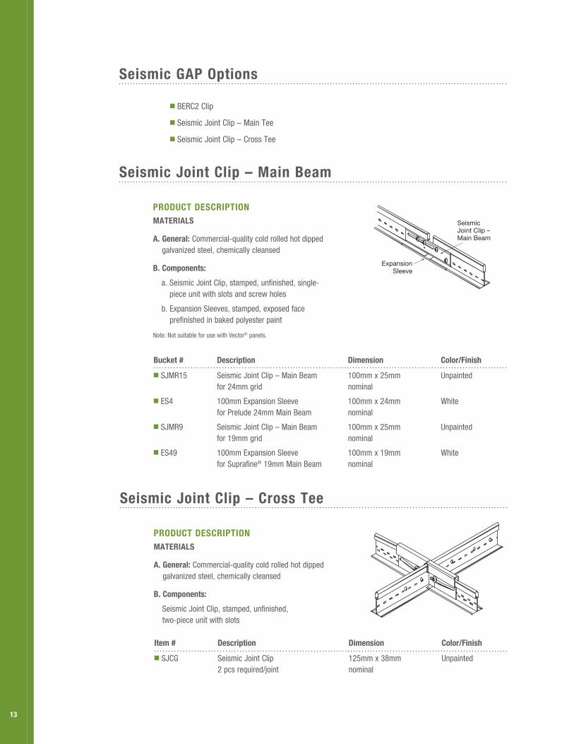
Seismic Joint Clip – Cross tee
proDuCt DeSCriptionmateriaLS
a. general: Commercial-quality cold rolled hot dipped galvanized steel, chemically cleansed
B. Components:
Seismic Joint Clip, stamped, unfinished, two-piece unit with slots
item # Description Dimension Color/finish
■ SJCG Seismic Joint Clip 2 pcs required/joint
125mm x 38mm nominal
Unpainted
Seismic gap options
■ BERC2 Clip
■ Seismic Joint Clip – Main Tee
■ Seismic Joint Clip – Cross Tee
Seismic Joint Clip – main Beam
proDuCt DeSCriptionmateriaLS
a. general: Commercial-quality cold rolled hot dipped galvanized steel, chemically cleansed
B. Components:
a. Seismic Joint Clip, stamped, unfinished, single- piece unit with slots and screw holes
b. Expansion Sleeves, stamped, exposed face prefinished in baked polyester paint
Note: Not suitable for use with Vector® panels.
Bucket # Description Dimension Color/finish
■ SJMR15 Seismic Joint Clip – Main Beam for 24mm grid
100mm x 25mm nominal
Unpainted
■ ES4 100mm Expansion Sleeve for Prelude 24mm Main Beam
100mm x 24mm nominal
White
■ SJMR9 Seismic Joint Clip – Main Beam for 19mm grid
100mm x 25mm nominal
Unpainted
■ ES49 100mm Expansion Sleeve for Suprafine® 19mm Main Beam
100mm x 19mm nominal
White
ExpansionSleeve
Seismic Joint Clip –Main Beam
13

Simple to install with these easy Steps
HoW to inStaLL tHe SeiSmiC Joint CLip – main Beam
Step 1: Determine which splices will receive the separation joint by dividing the total area into sections not greater than 250m2. Attach a hanger wire within 75mm of the splice that will receive the clip.
Step 2: Install complete grid system. Follow typical procedures except that all main beam splices must line up across the space.
Step 3: Prepare the main beam splice to receive the separation joint clip by cutting the locking tab from the left side of the connection and removing 19mm from the end of the beam on the right.
Step 4: Install the clip using the screws provided. Screws #1 and #2 install through the holes in the clip and into the right-hand main beam.
Step 5: Align the indexing nib with the lower hole on the left-hand main beam and insert screws #3 and #4 into the upper holes.
Step 6: Snap ES4 or ES49 expansion sleeve over the gap at the face of the main beam and crimp the four corners with a pair of pliers.
Step 7: Install SJCG cross tee separation joint clips at one end of every cross tee that spans the area of main beam separation.
#3#4
#1#2Indexing
Nib
1-1/16"
2-3/8"1-1/2"
3/4"
4"
10mm from Centerline
SeiSmiC rx CoDe CompLiant SoLutionS anD BenefitS (eSr-1308)
■ Narrow, sleek aesthetic with standard 22mm molding
■ Eliminates installation and aesthetic problems associated with 50mm wall angle
■ Lower cost solution
■ Better access to the plenum
■ Eliminates stabilizer bars
■ Eliminates visible pop rivets through the wall angle
■ More profiles from which to choose
■ Perimeter Support wires within 400mm
■ Attached grid on two adjacent walls with the BERC2 clip or pop rivets
■ BERC2 clip with 19mm clearance on unattached walls
■ Allows for minimum 19mm movement of cross tee or main beam towards and away from the wall (total movement of 38mm)
Seismic rx® approach
XX
2' o.c.
BB B
B
B
B
B
B
X X
XX
Una
ttach
ed W
all
B
B
B
Attached Wall
B or PB or PB or P
X X
Unattached Wall
7/8"
8" Max.
Pop Rivet
8" Max.
7/8" 3/4"
Screw optional
8" Max.
7/8"
attached Wall
unattached Wall
X Hanger WireB BERC or BERC2 ClipP Pop Rivets
BerC2 Clips or pop rivets
14

armstrong.com/seismic
BPCS-4609-413
All trademarks used herein are the property of AWI Licensing Company and/or its affiliates © 2013 AWI Licensing Company
List of seismic factors for specific towns/cities.
City/Town Z
Akaroa 0.3
Alexandra 0.21
Arrowtown 0.3
Arthurs Pass 0.6
Ashburton 0.2
Auckland 0.13
Balclutha 0.13
Blenheim 0.33
Bluff 0.15
Bulls 0.31
Cambridge 0.18
Cheviot 0.4
Christchurch 0.396*
Cromwell 0.24
Dannevirke 0.42
Darfield 0.396*
Dargaville 0.13
Dunedin 0.13
Eastbourne-Point Howard 0.4
Fairlie 0.24
Feilding 0.37
Fox Glacier 0.44
Foxton/Foxton Beach 0.36
Franz Josef 0.44
Geraldine 0.19
Gisborne 0.36
Gore 0.18
Greymouth 0.37
Hamilton 0.16
Hanmer Springs 0.55
Harihari 0.46
Hastings 0.39
Hawera 0.18
Hokitika 0.45
Huntly 0.15
Hutt Valley 0.4
Inglewood 0.18
Invercargill 0.17
Kaikohe 0.13
Kaikoura 0.42
Kaitaia 0.13
Kawerau 0.29
Levin 0.4
City/Town Z
Mangakino 0.21
Manukau City 0.13
Marton 0.3
Masterton 0.42
Matamata 0.19
Mataura 0.17
Milford Sound 0.54
Morrinsville 0.18
Mosgiel 0.13
Motueka 0.26
Mount Maunganui 0.2
Mt Cook 0.38
Murchison 0.34
Murupara 0.3
Napier 0.38
Nelson 0.27
New Plymouth 0.18
Ngaruawahia 0.15
Oamaru 0.13
Oban 0.14
Ohakune 0.27
Opotiki 0.3
Opunake 0.18
Otaki 0.4
Otira 0.6
Otorohanga 0.17
Paeroa 0.18
Pahiatua 0.42
Paihia/Russell 0.13
Palmerston North 0.38
Palmerston 0.13
Paraparaumu 0.4
Patea 0.19
Picton 0.3
Porirua 0.4
Pukekohe 0.13
Putaruru 0.21
Queenstown 0.32
Raetihi 0.26
Rangiora 0.4356*
Reefton 0.37
Riverton 0.2
Rotorua 0.24
City/Town Z
Ruatoria 0.33
Seddon 0.4
Springs Junction 0.45
St Arnaud 0.36
Stratford 0.18
Taihape 0.33
Takaka 0.23
Taumarunui 0.21
Taupo 0.28
Tauranga 0.2
Te Anau 0.36
Te Aroha 0.18
Te Awamutu 0.17
Te Kuiti 0.18
Te Puke 0.22
Temuka 0.17
Thames 0.16
Timaru 0.15
Tokoroa 0.21
Turangi 0.27
Twizel 0.27
Upper Hutt 0.42
Waihi 0.18
Waikanae 0.4
Waimate 0.14
Wainuiomata 0.4
Waiouru 0.29
Waipawa 0.41
Waipukurau 0.41
Wairoa 0.37
Waitara 0.18
Waiuku 0.13
Wanaka 0.3
Wanganui 0.25
Ward 0.4
Warkworth 0.13
Wellington 0.4
Wellington CBD 0.4
Westport 0.3
Whakatane 0.3
Whangarei 0.13
Winton 0.2
Woodville 0.41
* Denotes Z value has been adjusted to account for higher return period required in these areas.
Auckland Branch 20 Vestey DriveMt WellingtonP O Box 12349, PenroseAuckland 1642PH 09 276 4000FX 09 276 5757
Hamilton Branch 39A Northway StreetTe RapaP O Box 10332Hamilton 3241PH 07 850 8395FX 07 850 8394
Rotorua Branch 9 Monokia StreetP.O Box 1662Rotorua 3040PH 07 348 0951FX 07 347 1839
Wellington Branch 77 Port RoadSeaviewP.O Box 38581Wellington 5045PH: 04 576 2006FAX: 04 568 3413
Christchurch Branch Unit 9 24 Disraeli StreetAddingtonP.O Box 22132Christchurch 8140PH: 03 379 9329FAX: 03 365 6118
Dunedin Branch 8 Kitchener StP.O Box 243Dunedin 9054PH: 03 474 1800FAX: 03 474 1600
for more information
Recommended