Solutions by the people of Zimmer Spine.zimmerspine.com
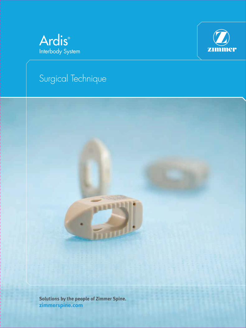
Ardis®
Interbody System
Surgical Technique

A more advanced interbody solution. From the people of Zimmer Spine.
The easily inserted Ardis Interbody System facilitates an efficient, reproducible fusion procedure with a self-distracting nose, convex geometry and wide range of sizes. This unique interbody system is designed for versatility and it can be used in a variety of open or MIS surgical applications. The Ardis System comes complete with best-in-class instrumentation and is backed by the training, service and expertise that surgeons have come to expect from Zimmer Spine. A variety of options to fit your needs and your patient’s anatomy.
A complete MIS solution. The Ardis System can be used as part of Zimmer Spine’s industry-leading MIS portfolio. Minimally invasive procedures deliver less operative trauma to the patient when compared to open procedures. The benefits of this approach can include less pain and scarring, reduced operating time, accelerated patient recovery and minimized hospital stays. Zimmer Spine offers a complete MIS solution with best-in-class devices for disc preparation, access and fixation.

Description/Indications/Contraindications 1
Ardis Implants 3
Harmony™ Posterior Instruments 4
Ardis Instruments 5
Surgical Technique 7
Kit Contents 17
Warnings and Precautions 21
Table of Contents
1
Description/Indications/Contraindications
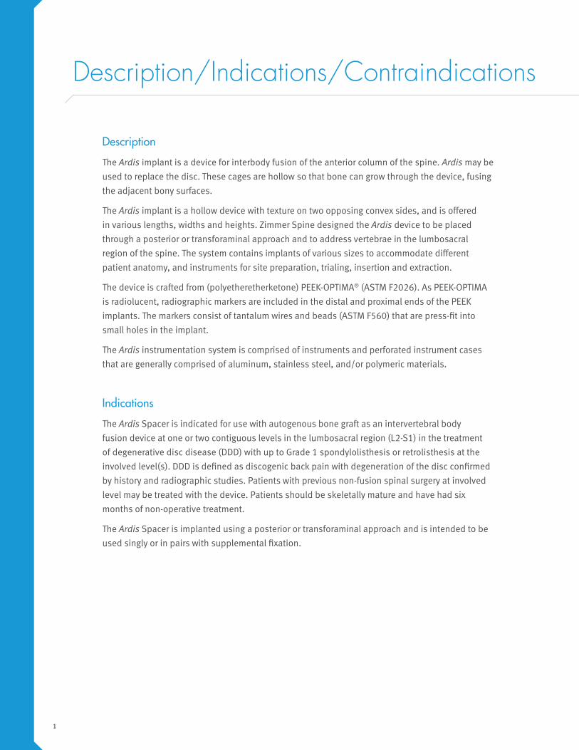
Description
The Ardis implant is a device for interbody fusion of the anterior column of the spine. Ardis may be
used to replace the disc. These cages are hollow so that bone can grow through the device, fusing
the adjacent bony surfaces.
The Ardis implant is a hollow device with texture on two opposing convex sides, and is offered
in various lengths, widths and heights. Zimmer Spine designed the Ardis device to be placed
through a posterior or transforaminal approach and to address vertebrae in the lumbosacral
region of the spine. The system contains implants of various sizes to accommodate different
patient anatomy, and instruments for site preparation, trialing, insertion and extraction.
The device is crafted from (polyetheretherketone) PEEK-OPTIMA® (ASTM F2026). As PEEK-OPTIMA
is radiolucent, radiographic markers are included in the distal and proximal ends of the PEEK
implants. The markers consist of tantalum wires and beads (ASTM F560) that are press-fit into
small holes in the implant.
The Ardis instrumentation system is comprised of instruments and perforated instrument cases
that are generally comprised of aluminum, stainless steel, and/or polymeric materials.
Indications
The Ardis Spacer is indicated for use with autogenous bone graft as an intervertebral body
fusion device at one or two contiguous levels in the lumbosacral region (L2-S1) in the treatment
of degenerative disc disease (DDD) with up to Grade 1 spondylolisthesis or retrolisthesis at the
involved level(s). DDD is defined as discogenic back pain with degeneration of the disc confirmed
by history and radiographic studies. Patients with previous non-fusion spinal surgery at involved
level may be treated with the device. Patients should be skeletally mature and have had six
months of non-operative treatment.
The Ardis Spacer is implanted using a posterior or transforaminal approach and is intended to be
used singly or in pairs with supplemental fixation.
2
Contraindications
1. Disease conditions which have been shown to be safely and predictably managed without the
use of internal fixation devices are relative contraindications to the use of these devices.
2. Active systemic infection or infection localized to the site of the proposed implantation are
contraindications to implantation.
3. Severe osteoporosis is a relative contraindication because it may prevent adequate fixation of
spinal anchors and thus preclude the use of this or any other posterior spinal instrumentation
system.
4. Any entity or condition that totally precludes the possibility of fusion, i.e. cancer, kidney
dialysis or osteopenia, is a relative contraindication. Other relative contraindications include
obesity, pregnancy, certain degenerative disease, and foreign body sensitivity. In addition, the
patient’s occupation or activity level or mental capacity may be relative contraindications to this
surgery. Specifically, some patients may, because of their occupation or lifestyle, or because
of conditions such as mental illness, alcoholism or drug abuse, place undue stresses on the
implant.
5. Known patient sensitivity to device materials (PEEK-OPTIMA).
6. Prior fusion at the level(s) to be treated.
7. Any condition not described in the indications for use.
3
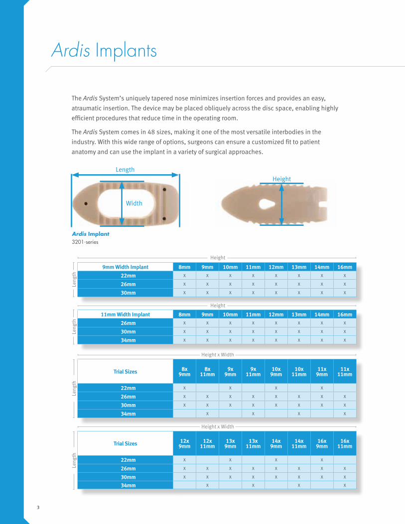
Ardis Implants
The Ardis System’s uniquely tapered nose minimizes insertion forces and provides an easy,
atraumatic insertion. The device may be placed obliquely across the disc space, enabling highly
efficient procedures that reduce time in the operating room.
The Ardis System comes in 48 sizes, making it one of the most versatile interbodies in the
industry. With this wide range of options, surgeons can ensure a customized fit to patient
anatomy and can use the implant in a variety of surgical approaches.
Height
Leng
th
Trial Sizes 8x 9mm
8x 11mm
9x 9mm
9x 11mm
10x 9mm
10x 11mm
11x 9mm
11x 11mm
22mm X X X X
26mm X X X X X X X X
30mm X X X X X X X X
34mm X X X X
Height x Width
Height
9mm Width Implant 8mm 9mm 10mm 11mm 12mm 13mm 14mm 16mm
22mm X X X X X X X X
26mm X X X X X X X X
30mm X X X X X X X X
Leng
th
i h id h
11mm Width Implant 8mm 9mm 10mm 11mm 12mm 13mm 14mm 16mm
26mm X X X X X X X X
30mm X X X X X X X X
34mm X X X X X X X X
Height
Leng
th
Trial Sizes 12x 9mm
12x 11mm
13x 9mm
13x 11mm
14x 9mm
14x 11mm
16x 9mm
16x 11mm
22mm X X X X
26mm X X X X X X X X
30mm X X X X X X X X
34mm X X X X
Height x Width
Leng
th
Ardis Implant 3201-series
Width
Length

4
Harmony Posterior Instruments
Curettes 2751-1, 2752-series, 2753-series, 2762-1, 2851-series
Prepare vertebral body endplates and remove disc material. Feature bayoneted shaft and reduced glare finish. Curettes available: Straight, Right, Left, Up-biting, Down-biting, Ring and O’Brien.
Smooth Distractors (6 - 15mm) 2654-06 to 2654-15
Incrementally distract the disc space.
Cutting Distractors (6 - 15mm) 2655-06 to 2655-15
Incrementally distract the disc space and shave vertebral endplates.
Pituitary Rongeurs (2 - 4mm) 2856-1-series, 2856-2-series
Cut boney structures and remove disc material. Feature bayoneted shaft and reduced glare finish.
Kerrison Rongeurs (2 - 4mm) 2855-1-series, 2855-2-series
Cut boney structures and remove disc material. Feature bayoneted shaft and reduced glare finish.
5
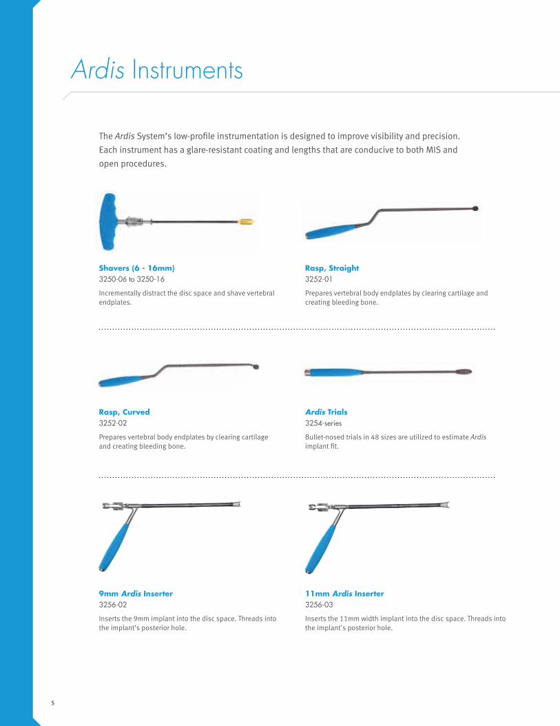
Ardis Instruments
The Ardis System’s low-profile instrumentation is designed to improve visibility and precision.
Each instrument has a glare-resistant coating and lengths that are conducive to both MIS and
open procedures.
Rasp, Curved 3252-02
Prepares vertebral body endplates by clearing cartilage and creating bleeding bone.
Shavers (6 - 16mm) 3250-06 to 3250-16
Incrementally distract the disc space and shave vertebral endplates.
Rasp, Straight 3252-01
Prepares vertebral body endplates by clearing cartilage and creating bleeding bone.
Ardis Trials 3254-series
Bullet-nosed trials in 48 sizes are utilized to estimate Ardis implant fit.
9mm Ardis Inserter 3256-02
Inserts the 9mm implant into the disc space. Threads into the implant’s posterior hole.
11mm Ardis Inserter 3256-03
Inserts the 11mm width implant into the disc space. Threads into the implant's posterior hole.
6
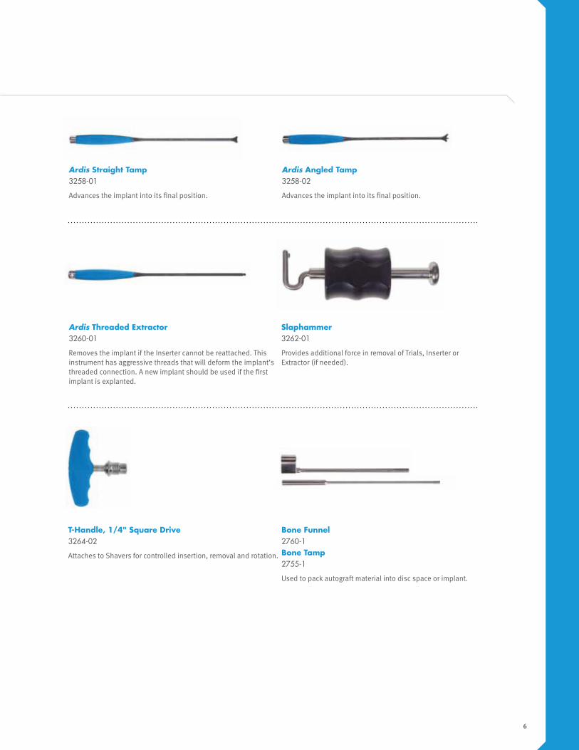
Ardis Angled Tamp 3258-02
Advances the implant into its final position.
Bone Funnel 2760-1Bone Tamp2755-1
Used to pack autograft material into disc space or implant.
Slaphammer 3262-01
Provides additional force in removal of Trials, Inserter or Extractor (if needed).
Ardis Threaded Extractor 3260-01
Removes the implant if the Inserter cannot be reattached. This instrument has aggressive threads that will deform the implant’s threaded connection. A new implant should be used if the first implant is explanted.
T-Handle, 1/4" Square Drive 3264-02
Attaches to Shavers for controlled insertion, removal and rotation.
Ardis Straight Tamp 3258-01
Advances the implant into its final position.
7
Surgical Technique
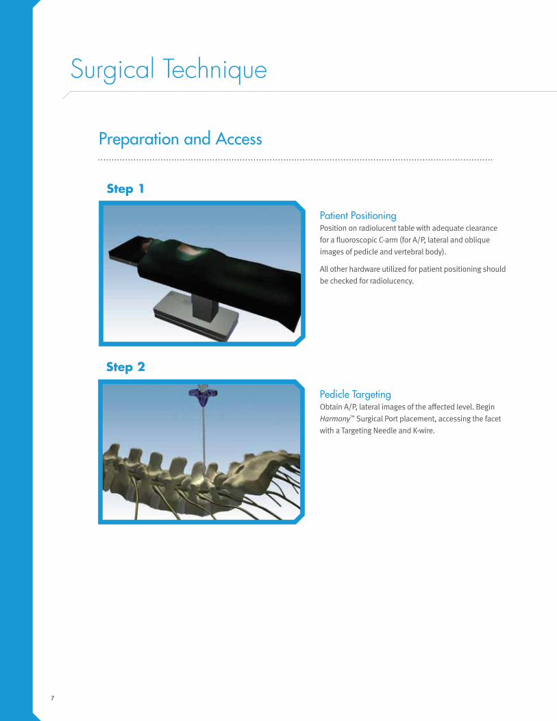
Patient PositioningPosition on radiolucent table with adequate clearance
for a fluoroscopic C-arm (for A/P, lateral and oblique
images of pedicle and vertebral body).
All other hardware utilized for patient positioning should
be checked for radiolucency.
Pedicle TargetingObtain A/P, lateral images of the affected level. Begin
Harmony™ Surgical Port placement, accessing the facet
with a Targeting Needle and K-wire.
Step 1
Step 2
Preparation and Access
8
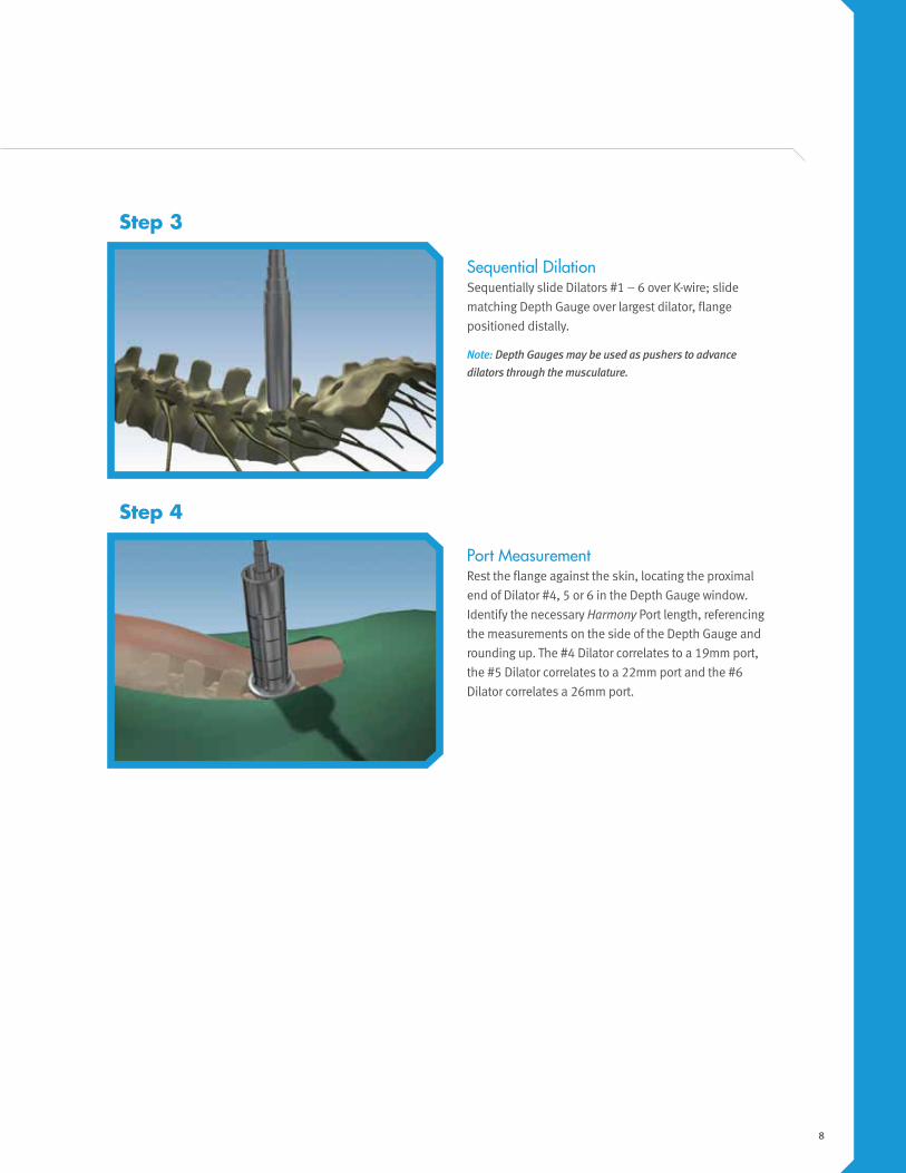
Sequential DilationSequentially slide Dilators #1 – 6 over K-wire; slide
matching Depth Gauge over largest dilator, flange
positioned distally.
Note: Depth Gauges may be used as pushers to advance dilators through the musculature.
Port MeasurementRest the flange against the skin, locating the proximal
end of Dilator #4, 5 or 6 in the Depth Gauge window.
Identify the necessary Harmony Port length, referencing
the measurements on the side of the Depth Gauge and
rounding up. The #4 Dilator correlates to a 19mm port,
the #5 Dilator correlates to a 22mm port and the #6
Dilator correlates a 26mm port.
Step 3
Step 4
9
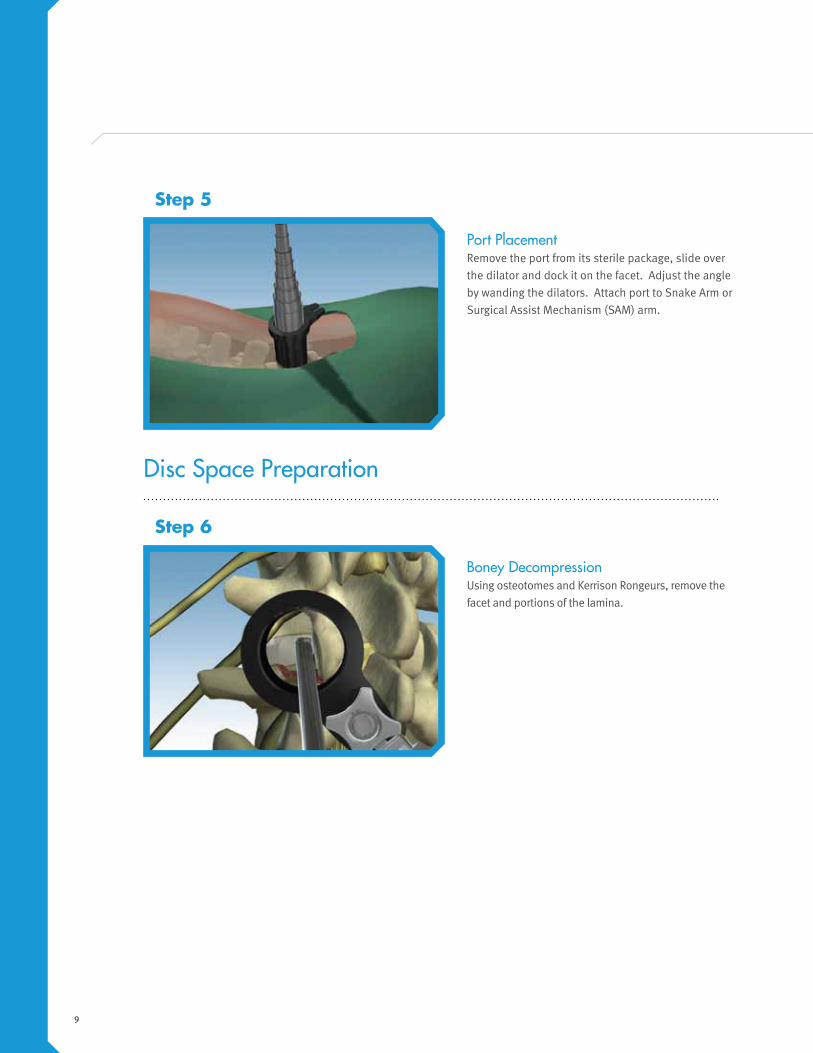
Boney DecompressionUsing osteotomes and Kerrison Rongeurs, remove the
facet and portions of the lamina.
Step 6
Disc Space Preparation
Port PlacementRemove the port from its sterile package, slide over
the dilator and dock it on the facet. Adjust the angle
by wanding the dilators. Attach port to Snake Arm or
Surgical Assist Mechanism (SAM) arm.
Step 5
10
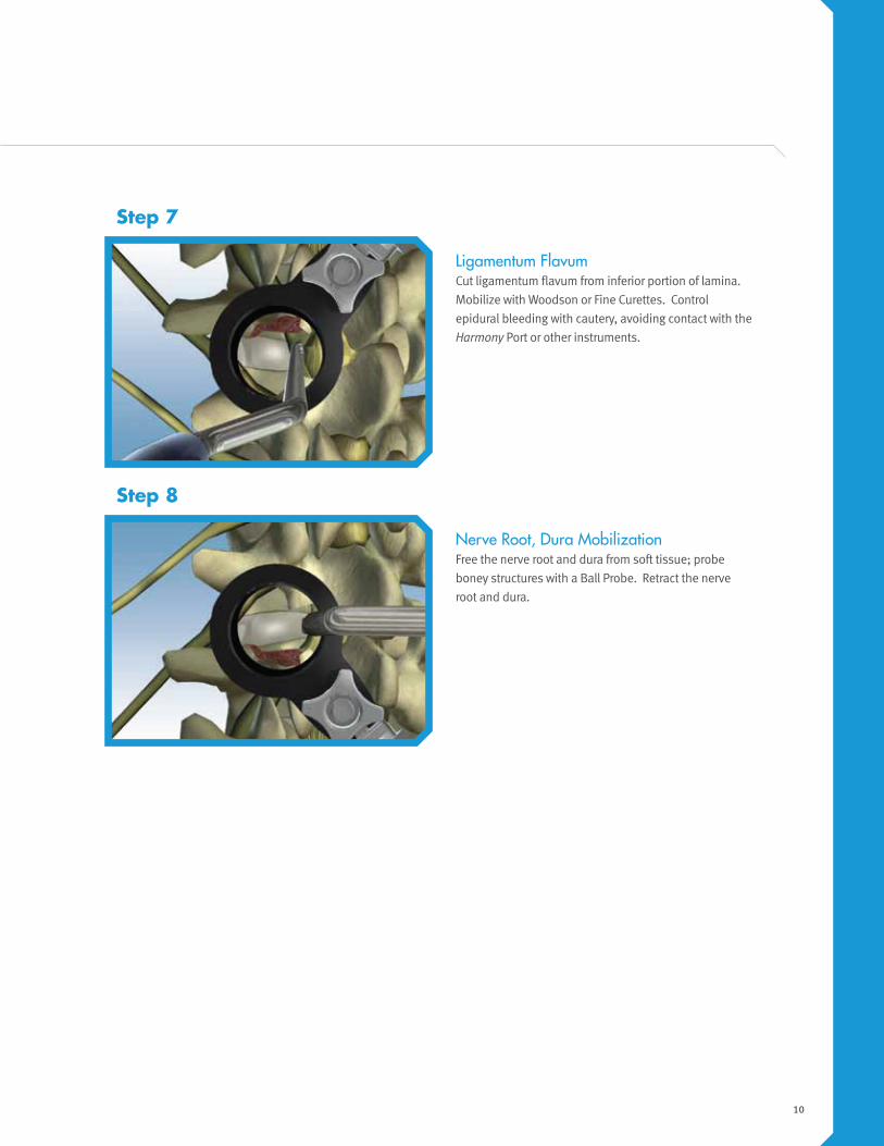
Ligamentum FlavumCut ligamentum flavum from inferior portion of lamina.
Mobilize with Woodson or Fine Curettes. Control
epidural bleeding with cautery, avoiding contact with the
Harmony Port or other instruments.
Nerve Root, Dura MobilizationFree the nerve root and dura from soft tissue; probe
boney structures with a Ball Probe. Retract the nerve
root and dura.
Step 7
Step 8
11
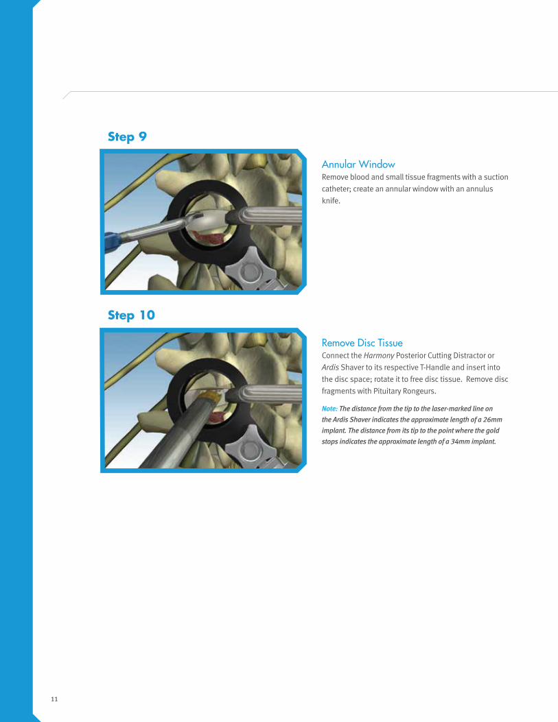
Annular WindowRemove blood and small tissue fragments with a suction
catheter; create an annular window with an annulus
knife.
Remove Disc TissueConnect the Harmony Posterior Cutting Distractor or
Ardis Shaver to its respective T-Handle and insert into
the disc space; rotate it to free disc tissue. Remove disc
fragments with Pituitary Rongeurs.
Note: The distance from the tip to the laser-marked line on the Ardis Shaver indicates the approximate length of a 26mm implant. The distance from its tip to the point where the gold stops indicates the approximate length of a 34mm implant.
Step 9
Step 10
12
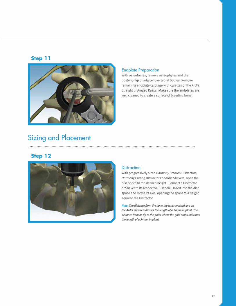
DistractionWith progressively sized Harmony Smooth Distractors,
Harmony Cutting Distractors or Ardis Shavers, open the
disc space to the desired height. Connect a Distractor
or Shaver to its respective T-Handle. Insert into the disc
space and rotate its axis, opening the space to a height
equal to the Distractor.
Note: The distance from the tip to the laser-marked line on the Ardis Shaver indicates the length of a 26mm implant. The distance from its tip to the point where the gold stops indicates the length of a 34mm implant.
Step 12
Sizing and Placement
Endplate PreparationWith osteotomes, remove osteophytes and the
posterior lip of adjacent vertebral bodies. Remove
remaining endplate cartilage with curettes or the Ardis
Straight or Angled Rasps. Make sure the endplates are
well cleaned to create a surface of bleeding bone.
Step 11
13
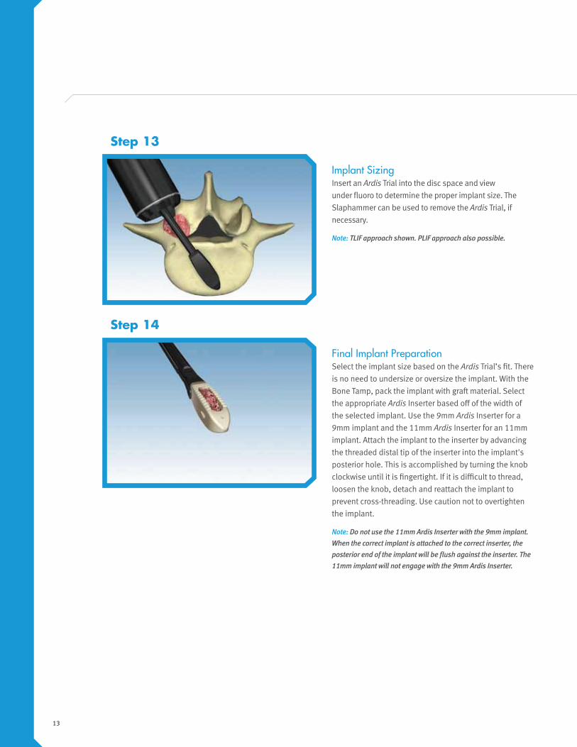
Implant SizingInsert an Ardis Trial into the disc space and view
under fluoro to determine the proper implant size. The
Slaphammer can be used to remove the Ardis Trial, if
necessary.
Note: TLIF approach shown. PLIF approach also possible.
Final Implant PreparationSelect the implant size based on the Ardis Trial’s fit. There
is no need to undersize or oversize the implant. With the
Bone Tamp, pack the implant with graft material. Select
the appropriate Ardis Inserter based off of the width of
the selected implant. Use the 9mm Ardis Inserter for a
9mm implant and the 11mm Ardis Inserter for an 11mm
implant. Attach the implant to the inserter by advancing
the threaded distal tip of the inserter into the implant's
posterior hole. This is accomplished by turning the knob
clockwise until it is fingertight. If it is difficult to thread,
loosen the knob, detach and reattach the implant to
prevent cross-threading. Use caution not to overtighten
the implant.
Note: Do not use the 11mm Ardis Inserter with the 9mm implant. When the correct implant is attached to the correct inserter, the posterior end of the implant will be flush against the inserter. The 11mm implant will not engage with the 9mm Ardis Inserter.
Step 13
Step 14
14
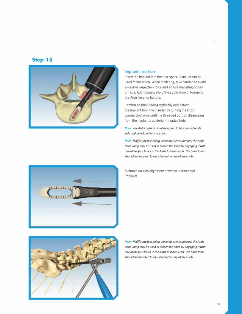
Implant InsertionInsert the implant into the disc space. A mallet can be
used for insertion. When malleting, take caution to avoid
excessive impaction force and ensure malleting occurs
on-axis. Additionally, avoid the application of torque to
the Ardis Inserter handle.
Confirm position radiographically and detach
the implant from the Inserter by turning the knob
counterclockwise until the threaded portion disengages
from the implant's posterior threaded hole.
Note: The Ardis System is not designed to be inserted on its
side and be rotated into position.
Note: If difficulty loosening the knob is encountered, the Ardis
Bone Tamp may be used to loosen the knob by engaging it with
one of the four holes in the Ardis Inserter knob. The bone tamp
should not be used to assist in tightening of the knob.
Maintain on-axis alignment between Inserter and
implants.
Step 15
Note: If difficulty loosening the knob is encountered, the Ardis
Bone Tamp may be used to loosen the knob by engaging it with
one of the four holes in the Ardis Inserter knob. The bone tamp
should not be used to assist in tightening of the knob.
15
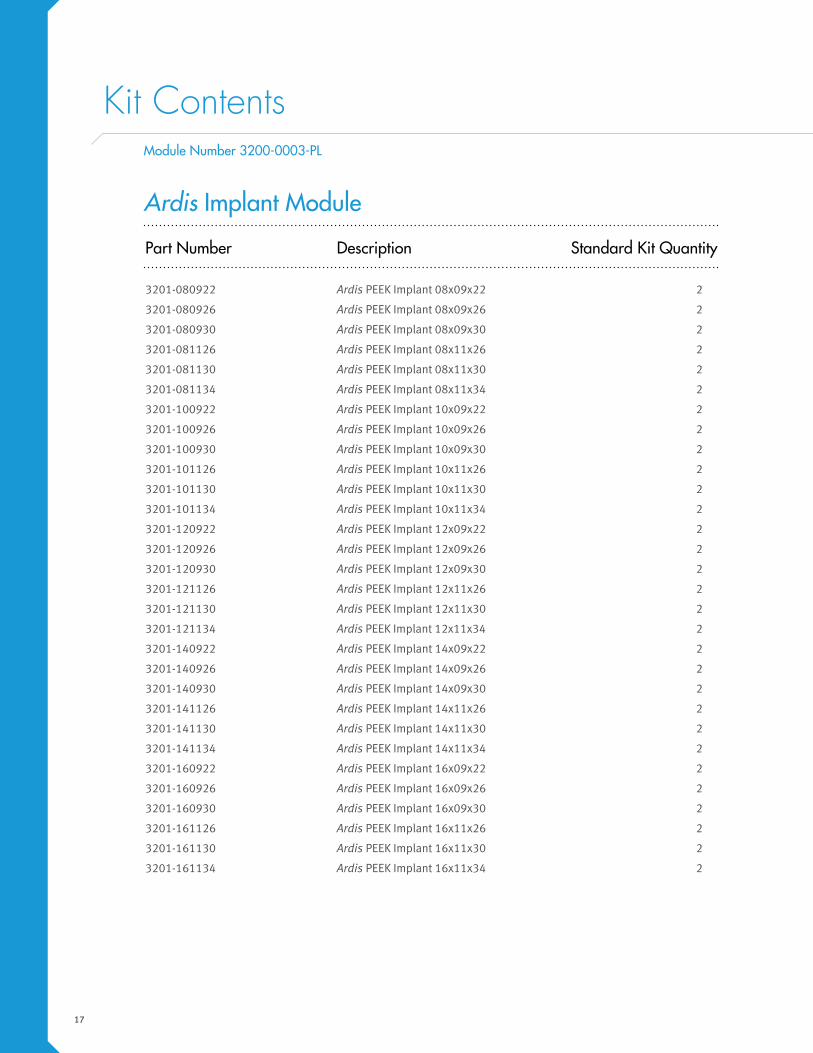
Position ConfirmationConfirm position radiographically.
Use the Bone Funnel/Bone Tamp to pack autogenous
graft material into the disc space around the implant.
Step 17
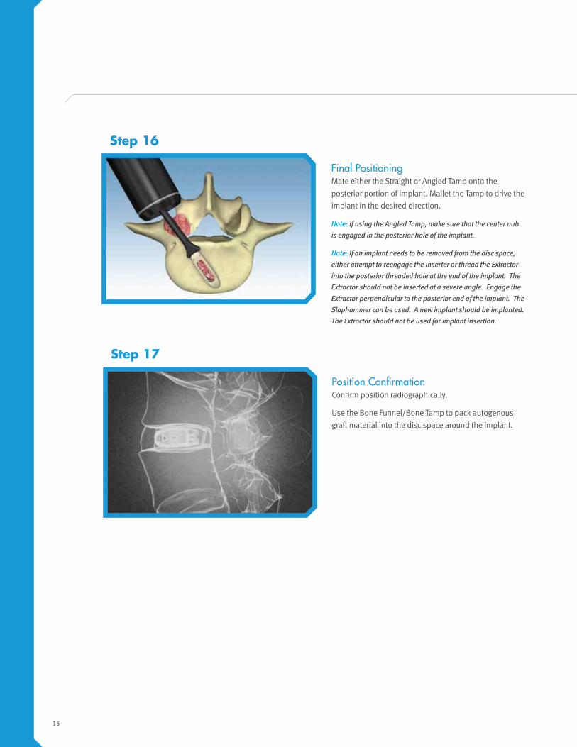
Final PositioningMate either the Straight or Angled Tamp onto the
posterior portion of implant. Mallet the Tamp to drive the
implant in the desired direction.
Note: If using the Angled Tamp, make sure that the center nub is engaged in the posterior hole of the implant.
Note: If an implant needs to be removed from the disc space, either attempt to reengage the Inserter or thread the Extractor into the posterior threaded hole at the end of the implant. The Extractor should not be inserted at a severe angle. Engage the Extractor perpendicular to the posterior end of the implant. The Slaphammer can be used. A new implant should be implanted. The Extractor should not be used for implant insertion.
Step 16

16
Implant Compression (If Necessary)Insert rods into the pedicle screw construct, completing
its assembly. Using the Compressor from the pedicle
screw system kit, apply a load to the Ardis implant and
lock the construct.
Step 18
Compression Option
Removal and Revision
Implant Removal or RevisionShould removal or revision of the implant be determined necessary early on post index procedure, it may still be possible
to remove the implant via the original approach. The Extractor can be used to thread into the posterior end of the implant
and be removed. The Slaphammer can be used if necessary. Once the healing process has begun, the surgeon may need
to consider alternative approaches such as direct anterior or lateral. An osteotome can be used at the interface between
the bone and both the superior and inferior faces of the implant to disengage the construct. This effectively cuts the
fused column of bone at the level of the interface. Once the implant has been disengaged, the implant can be removed.
Distraction can be used to allow easier access to the interface.
Intraoperative Implant RemovalShould removal of the device be required during surgery, the Inserter may be used to reengage the implant or the
Extractor can be used. If the Extractor is used, engage the instrument with the threaded posterior hole of the Ardis
implant and turn the handle clockwise until the threads bite into the PEEK material and the instrument is fully seated.
Connect the Slaphammer to the proximal end of the Inserter to remove the implant. Distraction will allow for easier
removal of the implant.
Note: Once the implant is removed, it should not be reinserted and a new implant should be used.
17
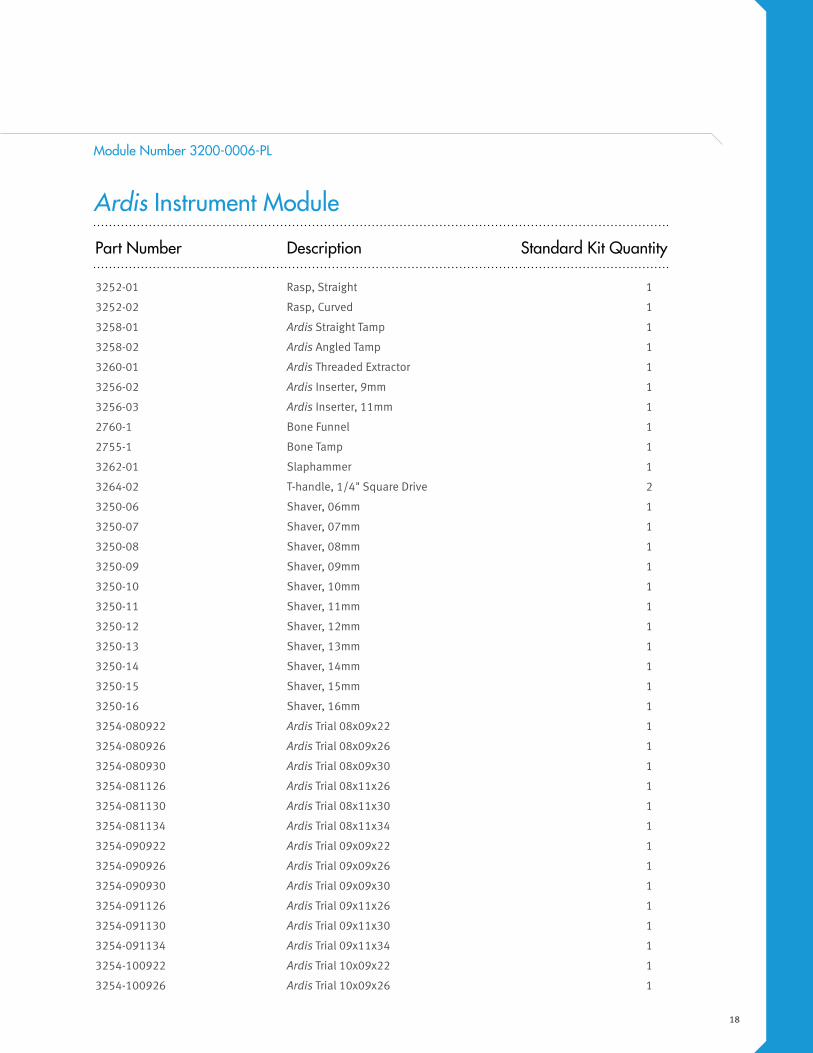
Kit Contents
Part Number Description Standard Kit Quantity
3201-080922 Ardis PEEK Implant 08x09x22 2
3201-080926 Ardis PEEK Implant 08x09x26 2
3201-080930 Ardis PEEK Implant 08x09x30 2
3201-081126 Ardis PEEK Implant 08x11x26 2
3201-081130 Ardis PEEK Implant 08x11x30 2
3201-081134 Ardis PEEK Implant 08x11x34 2
3201-100922 Ardis PEEK Implant 10x09x22 2
3201-100926 Ardis PEEK Implant 10x09x26 2
3201-100930 Ardis PEEK Implant 10x09x30 2
3201-101126 Ardis PEEK Implant 10x11x26 2
3201-101130 Ardis PEEK Implant 10x11x30 2
3201-101134 Ardis PEEK Implant 10x11x34 2
3201-120922 Ardis PEEK Implant 12x09x22 2
3201-120926 Ardis PEEK Implant 12x09x26 2
3201-120930 Ardis PEEK Implant 12x09x30 2
3201-121126 Ardis PEEK Implant 12x11x26 2
3201-121130 Ardis PEEK Implant 12x11x30 2
3201-121134 Ardis PEEK Implant 12x11x34 2
3201-140922 Ardis PEEK Implant 14x09x22 2
3201-140926 Ardis PEEK Implant 14x09x26 2
3201-140930 Ardis PEEK Implant 14x09x30 2
3201-141126 Ardis PEEK Implant 14x11x26 2
3201-141130 Ardis PEEK Implant 14x11x30 2
3201-141134 Ardis PEEK Implant 14x11x34 2
3201-160922 Ardis PEEK Implant 16x09x22 2
3201-160926 Ardis PEEK Implant 16x09x26 2
3201-160930 Ardis PEEK Implant 16x09x30 2
3201-161126 Ardis PEEK Implant 16x11x26 2
3201-161130 Ardis PEEK Implant 16x11x30 2
3201-161134 Ardis PEEK Implant 16x11x34 2
Ardis Implant Module
Module Number 3200-0003-PL
18
Part Number Description Standard Kit Quantity
3252-01 Rasp, Straight 1
3252-02 Rasp, Curved 1
3258-01 Ardis Straight Tamp 1
3258-02 Ardis Angled Tamp 1
3260-01 Ardis Threaded Extractor 1
3256-02 Ardis Inserter, 9mm 1
3256-03 Ardis Inserter, 11mm 1
2760-1 Bone Funnel 1
2755-1 Bone Tamp 1
3262-01 Slaphammer 1
3264-02 T-handle, 1/4" Square Drive 2
3250-06 Shaver, 06mm 1
3250-07 Shaver, 07mm 1
3250-08 Shaver, 08mm 1
3250-09 Shaver, 09mm 1
3250-10 Shaver, 10mm 1
3250-11 Shaver, 11mm 1
3250-12 Shaver, 12mm 1
3250-13 Shaver, 13mm 1
3250-14 Shaver, 14mm 1
3250-15 Shaver, 15mm 1
3250-16 Shaver, 16mm 1
3254-080922 Ardis Trial 08x09x22 1
3254-080926 Ardis Trial 08x09x26 1
3254-080930 Ardis Trial 08x09x30 1
3254-081126 Ardis Trial 08x11x26 1
3254-081130 Ardis Trial 08x11x30 1
3254-081134 Ardis Trial 08x11x34 1
3254-090922 Ardis Trial 09x09x22 1
3254-090926 Ardis Trial 09x09x26 1
3254-090930 Ardis Trial 09x09x30 1
3254-091126 Ardis Trial 09x11x26 1
3254-091130 Ardis Trial 09x11x30 1
3254-091134 Ardis Trial 09x11x34 1
3254-100922 Ardis Trial 10x09x22 1
3254-100926 Ardis Trial 10x09x26 1
Ardis Instrument Module
Module Number 3200-0006-PL

19
Part Number Description Standard Kit Quantity
3254-100930 Ardis Trial 10x09x30 1
3254-101126 Ardis Trial 10x11x26 1
3254-101130 Ardis Trial 10x11x30 1
3254-101134 Ardis Trial 10x11x34 1
3254-110922 Ardis Trial 11x09x22 1
3254-110926 Ardis Trial 11x09x26 1
3254-110930 Ardis Trial 11x09x30 1
3254-111126 Ardis Trial 11x11x26 1
3254-111130 Ardis Trial 11x11x30 1
3254-111134 Ardis Trial 11x11x34 1
3254-120922 Ardis Trial 12x09x22 1
3254-120926 Ardis Trial 12x09x26 1
3254-120930 Ardis Trial 12x09x30 1
3254-121126 Ardis Trial 12x11x26 1
3254-121130 Ardis Trial 12x11x30 1
3254-121134 Ardis Trial 12x11x34 1
3254-130922 Ardis Trial 13x09x22 1
3254-130926 Ardis Trial 13x09x26 1
3254-130930 Ardis Trial 13x09x30 1
3254-131126 Ardis Trial 13x09x26 1
3254-131130 Ardis Trial 13x11x30 1
3254-131134 Ardis Trial 13x11x34 1
3254-140922 Ardis Trial 14x09x22 1
3254-140926 Ardis Trial 14x09x26 1
3254-140930 Ardis Trial 14x09x30 1
3254-141126 Ardis Trial 14x11x26 1
3254-141130 Ardis Trial 14x11x30 1
3254-141134 Ardis Trial 14x11x34 1
3254-160922 Ardis Trial 16x09x22 1
3254-160926 Ardis Trial 16x09x26 1
3254-160930 Ardis Trial 16x09x30 1
3254-161126 Ardis Trial 16x11x26 1
3254-161130 Ardis Trial 16x11x30 1
3254-161134 Ardis Trial 16x11x34 1
3290-05 Ardis Trials Outer Base 1
3290-06 Ardis General Outer Base 1
Ardis Instrument Module (Continued)
Module Number 3200-0006-PL
20
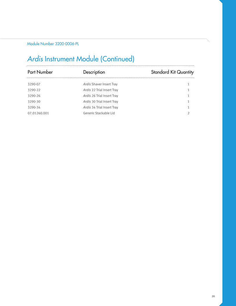
Part Number Description Standard Kit Quantity
3290-07 Ardis Shaver Insert Tray 1
3290-22 Ardis 22 Trial Insert Tray 1
3290-26 Ardis 26 Trial Insert Tray 1
3290-30 Ardis 30 Trial Insert Tray 1
3290-34 Ardis 34 Trial Insert Tray 1
07.01260.001 Generic Stackable Lid 2
Ardis Instrument Module (Continued)
Module Number 3200-0006-PL

21
Warnings and Precautions
Warnings
Following are specific warnings, precautions, and adverse effects, which should be understood by
the surgeon and explained to the patients. These warnings do not include all adverse effects, which
can occur with surgery in general, but are important considerations particular to metallic internal
fixation devices. General surgical risks should be explained to the patient prior to surgery.
1. Potential risks identified with the use of this device system, which may require additional
surgery, include:
a) Device component fracture.
b) Loss of fixation.
c) Non-union.
d) Fracture of the vertebra.
e) Neurological injury.
f) Vascular or visceral injury.
2. CORRECT SELECTION OF THE IMPLANT IS EXTREMELY IMPORTANT. The potential for satisfactory
fixation is increased by the selection of the proper size, shape and design of the implant.
While proper selection can help minimize risks, the size and shape of human bones present
limitations on the size, shape, and strength of implants. Use of provided trials is recommended.
3. IMPLANTS CAN BREAK WHEN SUBJECTED TO THE INCREASED LOADING ASSOCIATED WITH
DELAYED UNION OR NON-UNION. Internal fixation appliances are load sharing devices which
are used to obtain an alignment until normal healing occurs. If healing is delayed or does
not occur, the implant may eventually break due to fatigue. The degree or success of union,
loads produced by weight bearing, and activity levels will, among other conditions, dictate
the longevity of the implant. Notches, scratches or bending of the implant during the course
of surgery may also contribute to early failure. Patients should be fully informed of the risks of
implant failure.
22
4. PATIENT SELECTION. In selecting patients for internal fixation devices, the following factors can
be of extreme importance to the eventual success of the procedure:
a) The patient’s weight. An overweight or obese patient can produce loads on the device that
can lead to a loss of interbody height or failure of the device and/or the operation.
b) The patient’s occupation or activity. If the patient is involved in an occupation or activity
that includes substantial walking, running, lifting or muscle strain, the resultant forces can
cause loss of disc height and/or failure of the device.
c) A condition of senility, mental illness, alcoholism, or drug abuse. These conditions, among
others, may cause the patient to ignore certain necessary limitations and precautions in the
use of the appliance, leading to implant failure or other complications.
d) Certain degenerative diseases. In some cases, the progression of degenerative disease may
be so advanced at the time of implantation that it may substantially decrease the expected
useful life of the appliance. For such cases, orthopaedic devices can only be considered a
delaying technique or temporary relief.
e) Foreign body sensitivity. Where material sensitivity is suspected, appropriate tests should
be made prior to material selection or implantation.
f) Smoking. Patients who smoke have been observed to experience higher rates of
pseudarthrosis following surgical procedures where bone graft is used.
5. These warnings do not include all adverse effects that can occur with surgery in general. General
surgical risks should be explained to the patients prior to surgery.
6. Patients with previous spinal surgery at the level(s) to be treated may have different clinical
outcomes compared to those without a previous surgery.
23
Precautions
1. Prior to use, the physician should be trained in the surgical procedure recommended for the
use of this device.
2. The Ardis Device is a single use device and should not be reused. An explanted device should
never be reimplanted. Possible risks associated with re-use of single use devices include:
Mechanical Malfunction
Transmission of infectious agents
3. The DEVICE has not been evaluated for safety and compatibility in the MR environment. The
DEVICE has not been tested for heating or migration in the MR environment.
Instruments Warnings and Precautions
1. Instruments must be thoroughly cleaned prior to sterilization. Instruments that are not clean
may not be effectively sterilized.
2. Automated cleaning may not be effective. A thorough, manual cleaning process is
recommended.
3. When handling sharp instruments, use extreme caution to avoid injury.
4. Unless otherwise indicated, instrument sets are provided non-sterile and must be sterilized
prior to use.
5. Do not reuse instruments labeled for single use only. Reuse may adversely affect performance
of the instrument.
6. Flash autoclaving should be avoided whenever possible. Instruments should never be flash
autoclaved in an instrument case.

24
Solutions by the people of Zimmer Spine.
You are devoted to helping your patients reduce their pain and improve their lives.
And the people of Zimmer Spine are devoted to you. We are dedicated to supporting
you with best-in-class tools, instruments and implants. We are driven by the opportunity
to share our unrivaled education and training. We are committed partners who will
do everything in our power to assist you in your quest to provide the absolute best in
spinal care. And we can be counted on always to act with integrity as ethical partners
who are worthy of your trust. We are the people of Zimmer Spine.
Manufactured by:
Zimmer Spine7375 Bush Lake RoadMinneapolis, MN 55439800.655.2614
Zimmer LimitedSN3 4FP, U.K.+44.1793.58.4500
zimmerspine.com
L1467 Rev. D (07/13)(851S-1040-00) © 2013 Zimmer Spine, Inc.PEEK-OPTIMA® Polymer is a registered trademark of Invibio Ltd.
Disclaimer:This documentation is intended exclusively for physicians and is not intended for laypersons. Information on the products and procedures contained in this document is of a general nature and does not represent and does not constitute medical advice or recommendations. Because this information does not purport to constitute any diagnostic or therapeutic statement with regard to any individual medical case, each patient must be examined and advised individually, and this document does not replace the need for such examination and/or advice in whole or in part. Please refer to the package inserts for important product information, including, but not limited to, indications, contraindications, warnings, precautions, and adverse effects.
Caution: Federal (USA) law restricts this device to sale by or on the order of a physician. Please see the product Instructions for Use for a complete listing of the indications, contraindications, warnings, precautions and adverse effects.
Recommended