Air Force Institute of TechnologyAFIT Scholar
Theses and Dissertations Student Graduate Works
9-15-2016
Application of Executable Architecture in EarlyConcept Evaluation using the DoD ArchitectureFrameworkZhongwang Chua
Follow this and additional works at: https://scholar.afit.edu/etd
Part of the Systems Engineering Commons
This Thesis is brought to you for free and open access by the Student Graduate Works at AFIT Scholar. It has been accepted for inclusion in Theses andDissertations by an authorized administrator of AFIT Scholar. For more information, please contact [email protected].
Recommended CitationChua, Zhongwang, "Application of Executable Architecture in Early Concept Evaluation using the DoD Architecture Framework"(2016). Theses and Dissertations. 268.https://scholar.afit.edu/etd/268
APPLICATION OF EXECUTABLE ARCHITECTURE IN EARLY CONCEPT EVALUATION USING THE DOD ARCHITECTURE FRAMEWORK
THESIS
Zhongwang Chua, Military Expert 5 (Major), Republic of Singapore Air Force
AFIT-ENV-MS-16-S-038
DEPARTMENT OF THE AIR FORCE AIR UNIVERSITY
AIR FORCE INSTITUTE OF TECHNOLOGY
Wright-Patterson Air Force Base, Ohio
DISTRIBUTION STATEMENT A APPROVED FOR PUBLIC RELEASE; DISTRIBUTION UNLIMITED
The views expressed in this thesis are those of the author and do not reflect the official
policy or position of the United States Air Force, Department of Defense, the U.S.
Government, the corresponding agencies of any other government, the North Atlantic
Treaty Organization or any other defense organization.
AFIT-ENV-MS-16-S-038
APPLICATION OF EXECUTABLE ARCHITECTURE IN EARLY CONCEPT EVALUATION USING THE DOD ARCHITECTURE FRAMEWORK
THESIS
Presented to the Faculty
Department of Systems Engineering and Management
Graduate School of Engineering and Management
Air Force Institute of Technology
Air University
Air Education and Training Command
In Partial Fulfillment of the Requirements for the
Degree of Master of Science in Systems Engineering
Zhongwang Chua, BS (Hons)
Military Expert 5 (Major), Republic of Singapore Air Force
September 2016
DISTRIBUTION STATEMENT A
APPROVED FOR PUBLIC RELEASE; DISTRIBUTION UNLIMITED
AFIT-ENV-MS-16-S-038
APPLICATION OF EXECUTABLE ARCHITECTURE IN EARLY CONCEPT EVALUATION USING THE DOD ARCHITECTURE FRAMEWORK
Zhongwang Chua, BS (Hons)
Military Expert 5 (Major), Republic of Singapore Air Force
Committee Membership:
Dr. David R. Jacques Chair
Dr. John M. Colombi Member
Maj Christina Rusnock, Ph. D Member

iv
Acknowledgments
I would like to express my sincere appreciation to my faculty advisor, Dr David Jacques,
for his guidance and support throughout the course of this thesis effort. The insight and
experience was certainly appreciated. I would also like to recognize the contribution of
my teammates, Capt Andrews Roberts, Lidia Toscano and Capt Nicholas Gilbert, for
their cooperation in the development of related architectural products for SENG 640.
Most importantly, I sincerely thank my family for their support and patience during the
course of my studies.
Zhongwang Chua
v
Table of Contents
Page
Acknowledgments.............................................................................................................. iv
Table of Contents .................................................................................................................v
List of Figures .................................................................................................................. viii
List of Tables ..................................................................................................................... xi
List of Acronyms ............................................................................................................. xiii
Abstract ..............................................................................................................................xv
I. Introduction .....................................................................................................................1
Overview ......................................................................................................................1
Motivation ....................................................................................................................2
Problem Statement........................................................................................................5
Research Objectives .....................................................................................................6
Research Focus .............................................................................................................7
Methodology Overview ................................................................................................7
Assumptions .................................................................................................................8
Preview .........................................................................................................................9
II. Literature Review ..........................................................................................................10
Overview ....................................................................................................................10
System Architecting as a viable solution....................................................................10
DoDAF as Tool for Early Concept Evaluation in DoD .............................................13
System Architecting—From Static Viewpoints to Dynamic Executable Models ......15
Conclusion ..................................................................................................................32
III. Methodology ................................................................................................................33
vi
Chapter Overview .......................................................................................................33
Overview of Research Methodology ..........................................................................34
Implementation of Methodology ................................................................................36
Conclusion ..................................................................................................................70
IV. Analysis and Results ...................................................................................................71
Chapter Overview .......................................................................................................71
Statistical Methods Application .................................................................................71
Analysis of Results: MOE 1—Target Acquisition Percentage ..................................75
Analysis of Results: MOE 2—False Alarm Percentage .............................................82
Analysis of Results: MOE 3—Time-to-Strike ...........................................................89
Analysis of Results: MOE 4—Target Destruction Percentage ..................................97
Objective Hierarchy Process ....................................................................................104
Summary...................................................................................................................105
V. Conclusions and Recommendations ..........................................................................107
Introduction of Research ..........................................................................................107
Research Question 1: Which views of DoDAF are critical for effective construction
of EA? .......................................................................................................................107
Research Question 2: What level of Operational or functional hierarchy of
component sub-systems is required for EA to be effective? ....................................110
Research Question 3: How can EA be used to identify and evaluate the impact of
design parameters on MOEs and MOPs? .................................................................112
Research Question 4: Which are the key parameters that have significant impact to
design and operational cost for the multi-tiered UAV architecture considered herein?114

vii
Effectiveness of Innoslate Software in EA ...............................................................116
Recommendations for Future Research....................................................................117
Summary or Significance of Research .....................................................................118
Appendix ..........................................................................................................................120
Bibliography ....................................................................................................................149
viii
List of Figures
Page
Figure 1: Commitment, system-specific knowledge, cost incurred and east of Change
(Blanchard & Fabrycky, 1998). ................................................................................... 3
Figure 2: Functional Reasons for Cost Over-run (Berteau et al., 2011) ............................. 5
Figure 3: Semantic Areas of UML (OMG UML, pg 14, 2015) ........................................ 21
Figure 4: Relationship between SysML and UML (OMG, 2015) .................................... 23
Figure 5: Relations between Static and Dynamic Models ................................................ 28
Figure 6: Example of Dynamic Results over time ............................................................ 30
Figure 7: Example of Pareto Frontier for different variation within each CA .................. 30
Figure 8: Classification of Different UAS tiers ................................................................ 38
Figure 9: Use Case Diagram ............................................................................................. 40
Figure 10: OV-1 of Multi-tiered UAS SoS ....................................................................... 48
Figure 11: OV-2 High level Resource Flow Diagram of Multi-tiered UAS SoS ............. 49
Figure 12: OV-5a Operational Activities Decomposition Tree ........................................ 50
Figure 13: OV-5B Activity Flow Diagram of the Multi-tiered UAS SoS ........................ 51
Figure 14: DIV 2 of Multi-tier UAS SoS.......................................................................... 54
Figure 15: Overview of Simulation .................................................................................. 57
Figure 16: Modified 0V-5B for Simulation ...................................................................... 58
Figure 17: Summary of Target Acquisition Percentage ................................................... 75
Figure 18: Summary of Target Acquisition MOE with 95% CI ....................................... 76
Figure 19: Main Effect Plot for Target Acquisition Percentage MOE ............................. 78
ix
Figure 20: Interaction Effect Plot for Target Acquisition Percentage MOE .................... 78
Figure 21: Analysis of Type of C2 on Target Acquisition Percentage MOE ................... 80
Figure 22: Analysis of Type of Sensor on Target Acquisition Percentage MOE ............. 80
Figure 23: Analysis of Number of Strike UAS on Target Acquisition Percentage MOE 80
Figure 24: Summary of False Alarm Percentage .............................................................. 82
Figure 25: Summary of False Alarm MOE with 95% CI ................................................. 83
Figure 26: Main Effect Plot for False Alarm Percentage MOE........................................ 85
Figure 27: Interaction Effect Plot for False Alarm Percentage MOE ............................... 85
Figure 28: Analysis of Type of C2 on False Alarm Percentage MOE ............................. 87
Figure 29: Analysis of Type of Sensor on False Alarm Percentage MOE ....................... 87
Figure 30: Analysis of Number of Strike UAS on False Alarm Percentage MOE ........... 87
Figure 31: Summary of Time-to-Strike ............................................................................ 89
Figure 32: Summary of Time-to-Strike MOE with 95% CI ............................................. 90
Figure 33: Main Effect Plot for Time-to-Strike MOE ...................................................... 92
Figure 34: Interaction Effect Plot for Time-to-Strike MOE ............................................. 92
Figure 35: Analysis of Type of C2 on Time-to-Strike MOE ............................................ 94
Figure 36: Analysis of Type of Sensor on Time-to--Strike MOE .................................... 94
Figure 37: Analysis of Number of Strike UAS on Time-to-Strike MOE ......................... 94
Figure 38: Summary of Target Destruction Percentage MOE .......................................... 97
Figure 39: Summary of Target Destruction MOE with 95% CI ....................................... 98
Figure 40: Main Effect Plot for Target Destruction Percentage MOE ........................... 100
Figure 41: Interaction Effect Plot for Target Destruction Percentage MOE .................. 100

x
Figure 42: Analysis of Type of C2 on Target Destruction Percentage MOE ................. 102
Figure 43: Analysis of Type of Sensor on Target Destruction Percentage MOE ........... 102
Figure 44: Analysis on Number of Strike UAS on Target Destruction Percentage MOE
.................................................................................................................................. 102
xi
List of Tables
Page
Table 1: Examples of Desirable and Undesirable Anticipated and Emergent System
Properties Influenced by Architecture (Crawley et al., 2004).................................... 12
Table 2: Comparisons of Methodologies .......................................................................... 17
Table 3: Terse Use Cases .................................................................................................. 40
Table 4: OV-6A Operational Rules Model ....................................................................... 52
Table 5: 8 Architectural Variants of Multi-tiered UAS SoS for concept evaluation ........ 64
Table 6: Time delay for different Activities Nodes .......................................................... 65
Table 7: Duration for Ingress Activities for different Variants ........................................ 67
Table 8: Probability of Detection given Real Target ........................................................ 68
Table 9: Probability of False Target detection .................................................................. 69
Table 10: Probability of TBM Destruction ....................................................................... 69
Table 11: Scenarios and variation of Design Parameters ................................................. 71
Table 12: Hypothesis Testing Result ................................................................................ 77
Table 13: One-way ANOVA for Design Parameters ....................................................... 79
Table 14: Hypothesis Testing Results............................................................................... 84
Table 15: One-way ANOVA for Design Parameters ....................................................... 86
Table 16: Hypothesis Testing Results............................................................................... 91
Table 17: One-way ANOVA for Design Parameters ....................................................... 93
Table 18: Hypothesis Testing Results............................................................................... 99
Table 19: One-way ANOVA for Design Parameters ..................................................... 101

xii
Table 20: OHP Analysis ................................................................................................. 104
Table 21: Summary of Design Parameters and MOEs ................................................... 105
Table 22: Assessment of DoDAF View for EA.............................................................. 108
Table 23: Summary of Design Parameters and MOEs ................................................... 114
xiii
List of Acronyms
ABEP Architectural-Base Evaluation Process
AO Area of Operations
CI Confidence Interval
CONOPS Concept of Operations
CPN Color Petri-Net
CRRA Capability Review and Risk Assessment
DM2 DoDAF Meta Model
DoD Department of Defense
DoDAF Department of Defense Architecture Framework
EA Executable Architecture
ESM Extended Sequence Modeling
ISR Intelligence, Surveillance and Reconnaissance
MDA Model-Driven Architecture
MDAP Major Defense Acquisition Program
MoDAF Ministry of Defense Architecture Framework
MOE Measure of Effectiveness
MOF Meta-Object Facility
MOP Measure of Performance
OMG Object Management Group
PIM Platform Independent Model
PSM Process Sequence Modeling
SE Systems Engineering
SoS System-of-Systems
SysML System Modeling Language
TBM Theater Ballistics Missile
TSEO Time Sensitive Effects Operation
UAS Unmanned Aircraft System

xiv
UML Unified Modeling Language
UPDM Unified Profile for DoDAF/MoDAF
XMI XML Metadata Interchange
XML Extensible Markup Language
xv
AFIT-ENV-MS-16-S-038
Abstract
The increasing complexity in the development of today’s modern warfighting
systems required a systematic evaluation approach in the assessment of the envisaged
capability and estimating the cost effectiveness, especially in the early stages of Concept
Development. This research focused on the development of early Concept Evaluation
methodology through the use of Executable Architecture (EA) through the System
Architecting process. Particularly, the methodology was applied in the assessment of a
proposed fictitious Multi-tiered Unmanned Aircraft System System-of-Systems that was
designed to provide target acquisition and conduct dynamic strike on Theater Ballistic
Missile launchers.
Through the implementation of the evaluation methodology using dynamic
modeling of the system-under-design, the research was able to provide quantitative
assessment of different design parameters on the overall system effectiveness, as
measured using a set of pre-determined Measures-of-Effectiveness. Innoslate was used to
develop the EA model of a fictitious multi-tier Unmanned Aircraft System System-of-
Systems, and provided quantitative assessment of the overall system performance due to
changes in the design parameters. The research showed that the proposed evaluation
methodology provide system architects with the tool to 1) evaluate different design
parameters, 2) understand the overall system capability given sub-system capabilities,
and 3) determine sub-system requirement given desired system performance.
1
APPLICATION OF EXECUTABLE ARCHITECTURE IN EARLY CONCEPT EVALUATION USING DOD ARCHITECTURE FRAMEWORK
I. Introduction
Overview
The increasing complexity in today’s modern warfighting systems demands a
systematic approach in evaluating the envisaged capability, and estimating the cost-
effectiveness of the proposed weapon system in the early stages of Concept
Development. To address this challenge, it is necessary that the evaluation methodology
has the capability and capacity to process highly complex system with many unknowns
under widely varying scenario. This research thesis builds on the efforts of Maj Ryan
Pospisal (Pospisal, 2015) in the use of executable architecting, and extends the research
focus to assess the impact of different design parameters to system performance and cost.
This research reviews an existing system architecting process as a viable solution
to provide program offices with early assessment and evaluation of Department of
Defense (DoD) projects and proposes a methodology using Executable Architecture (EA)
and dynamic models to provide a holistic evaluation of the proposed concept across
operational time and space. In this regard, this research will focus on the domain of
tactical Intelligence, Surveillance, and Reconnaissance (ISR) system development,
involving the use of multi-tiered Unmanned Aircraft Systems (UAS) to provide target
acquisition and conduct dynamic strike.
2
Motivation
The focus of this research is driven to achieving two key deliverables during
Concept Development phase—1) impact of system parameters on overall system-design
and operational effectiveness during early stage development, and 2) accuracy of cost
estimates for cost-effectiveness evaluation.
Impact of System Parameters during Concept Development Phase
During the early stages of Concept Development, the system-under-design is
often ill-defined, with many different possible configurations and design parameters that
can be implemented into the system to meet user requirements to varying degrees of
success. Indeed, MITRE defined Concept Development as:
a set of activities that are carried out early in the systems engineering life cycle to
collect and prioritize operational needs and challenges, develop alternative
concepts to meet the needs, and select a preferred one as the basis for subsequent
system or capability development and implementation.
From the above definition, it is essential that there exist a method to qualitatively
and quantitatively evaluate the different configurations and design parameters of the
proposed concept to select the optimal design parameters that best fulfil the user’s
requirements.
3
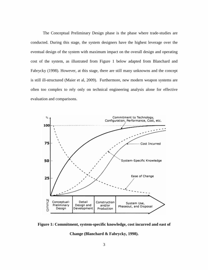
The Conceptual Preliminary Design phase is the phase where trade-studies are
conducted. During this stage, the system designers have the highest leverage over the
eventual design of the system with maximum impact on the overall design and operating
cost of the system, as illustrated from Figure 1 below adapted from Blanchard and
Fabrycky (1998). However, at this stage, there are still many unknowns and the concept
is still ill-structured (Maier et al, 2009). Furthermore, new modern weapon systems are
often too complex to rely only on technical engineering analysis alone for effective
evaluation and comparisons.
Figure 1: Commitment, system-specific knowledge, cost incurred and east of
Change (Blanchard & Fabrycky, 1998).

4
Accuracy of Cost Estimates for Cost-effectiveness Evaluation
The procurement and introduction of new technology continues to be a vital force
multiplier in the military. With the introduction of new technology and advancement in
System-of-Systems (SoS) operations, it is evident that there is an ever increasing
complexity in technology, software density and system integration, resulting in the
challenging task of estimating accurate system development costs at the inception of
major development activities (Arena et al., 2006). Indeed, a study by Younossi et al.
(2007) on 46 completed programs showed that the average cost growth ratio across all
programs was 1.46, or 46% higher than estimated at Milestone B. The team further
quantified that this could be attributed to higher level of new technology adaptation in
most DoD programs, resulting in inherently higher levels of cost and schedule
uncertainty and hence poor initial budget estimates by program offices.
With increasing complexity in today’s modern warfighting systems, a systematic
analytical approach from Concept Formulation to System Design and eventual operation
of the weapon systems is needed. However, the growing complexity has resulted in rising
risk to development cost and time. Indeed, from the Government Accountability Office’s
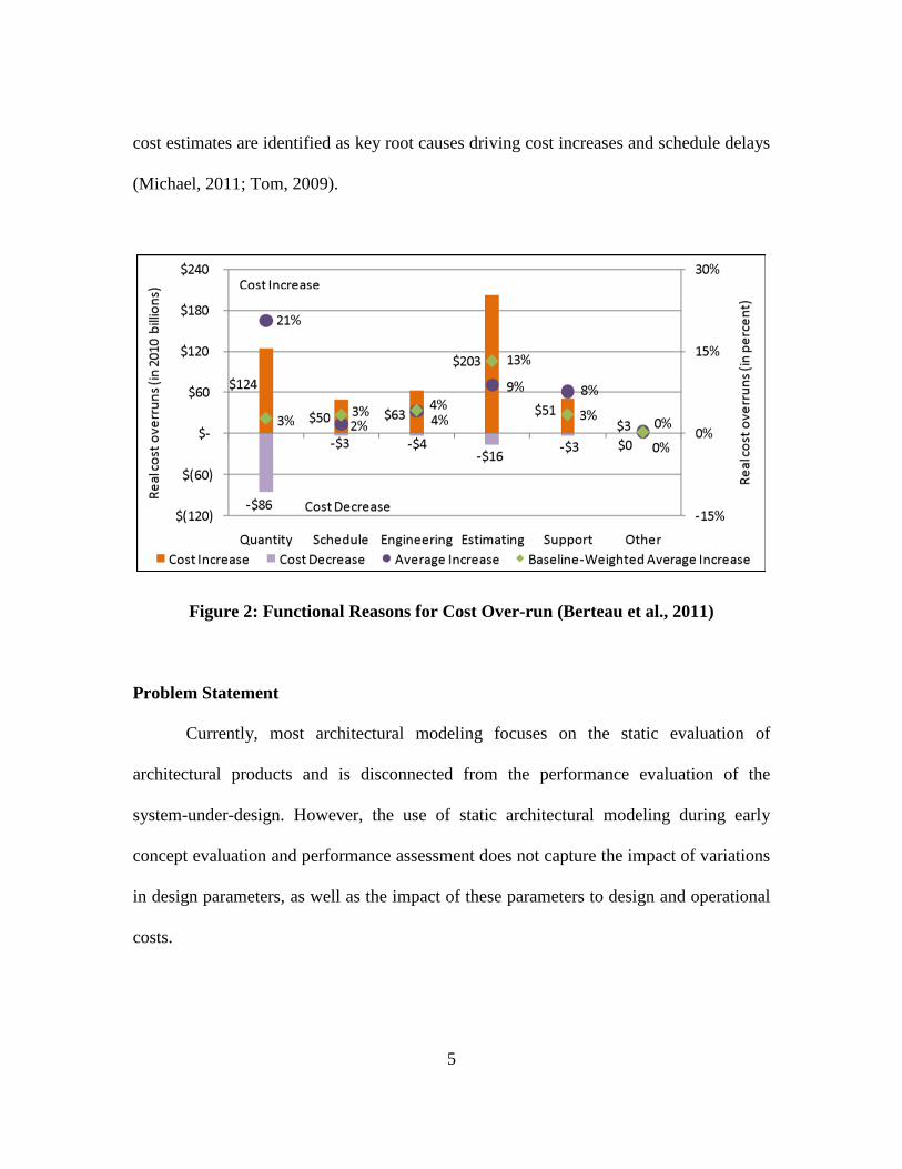
study (Berteau et al., 2011) in 2011, the 98 Major Defense Acquisition Programs
(MDAPs) had a total cost over-run of $402 billon and an average schedule delay of 22
months. The main reason for cost over-run was attributed to inaccurate cost estimates as
shown in Figure 2. Similar to the cost growth study, technical complexity and inaccurate
5
cost estimates are identified as key root causes driving cost increases and schedule delays
(Michael, 2011; Tom, 2009).
Figure 2: Functional Reasons for Cost Over-run (Berteau et al., 2011)
Problem Statement
Currently, most architectural modeling focuses on the static evaluation of
architectural products and is disconnected from the performance evaluation of the
system-under-design. However, the use of static architectural modeling during early
concept evaluation and performance assessment does not capture the impact of variations
in design parameters, as well as the impact of these parameters to design and operational
costs.
6
Research Objectives
This thesis investigates the utility of Executable Architecture in conducting early
concept evaluation of DoD-related projects, based on architectural products using
Department of Defense Architecture Framework (DoDAF). In particular, the research
focuses on addressing the following questions based on a hypothetical defense
development program to design and build a multi-tiered UAS ISR SoS:
Research Question 1: Which views of DoDAF are critical for effective
construction of EA?
Research Question 2: What level of operational or functional hierarchy of
component sub-systems is required for EA to be effective?
Research Question 3: How can EA be used to identify and evaluate the impact of
design parameters on Measure-of-Effectiveness (MOE) level and Measure-of-
Performance (MOP)?
Research Question 4: Which are the key parameters that have significant impact
to design and operational cost for the multi-tiered UAV architecture considered
here-in?
7
Research Focus
The focus of this research is to evaluate the utility of EA in the early assessment
of defense related projects based on DoDAF-driven architecture design. Specifically, the
research will focus on the domain of tactical ISR system development in an effort to
provide a basis for application in future ISR SoS development. Specifically, the system-
under-design aims to provide tactical ISR and dynamic strike through the use of a
fictitious multi-tiered UAS SoS that optimizes the deployment of UAS from different
tiers to effective search, locate and destroy theater ballistic missiles (TBM) launchers.
Methodology Overview
This thesis focuses on the following 3 areas: 1) Understand current EA
technology; 2) Develop EA models based on a proposed design concept; and 3) Evaluate
the effectiveness of the EA in response to the research questions.
Understand current EA technology. To achieve this, a literature review is
conducted in the field of EA to understand the different approaches to achieving an
accurate depiction of the proposed system architecture. In particular, the review will
focus on examining the different modeling languages in system architecting, and the
process to automate the transformation of static models to dynamic models. From the
result of the review, a suitable methodology and software, namely Innoslate (Innoslate,
2012), is selected for the implementation of EA.
8
Develop EA models based on proposed design concept. Different EA models
with architectural variations are developed based on a plausible Concept of Operations
(CONOPs) for multi-tiered UAS tactical ISR and dynamic strike systems. These EA
models are constructed based on the requirements set-forth under DoDAF.
Evaluate effectiveness of EA in response to research questions. The EA models
are evaluated, and different architectural variations are introduced to the system-under-
design to assess their impact to the overall performance. The results from these
simulations will be used to answer the research questions.
Assumptions
For the purpose of this research, the following assumptions are identified during
the system modeling and evaluation phase:
1. The methodology is scalable to include more complex individual systems and
SoS.
2. The selected sets of parameters under study are adequate to determine future
system performance.
3. A commercial tool, Innoslate (Innoslate, 2012), currently exists, and is
accessible to the author, and includes an executable modeling capability to
meet the fidelity requirements for this thesis.
9
Preview
While this research thesis focuses on the application of EA in providing early
concept evaluation of DoD-related problems, the methodology introduced in this thesis
can be easily modified to be implemented in other government agencies or commercial
entities to achieve the desired outcome. A preview of the thesis work is provided below:
Chapter 2: This chapter summarizes the results of the literature in the area of EA,
focusing on the different modeling languages and transformation techniques. This
chapter concludes with a comparison of the different approaches, and compares
and contrasts the main benefits and drawbacks of these approaches.
Chapter 3: This chapter elaborates on the methodology in the application of the
research efforts, and illustrates how the results were collected and analyzed.
Chapter 4: This chapter summarizes the results obtained from the conduct of the
research efforts, and the analysis of these results in fulfilling the research
objectives.
Chapter 5: This chapter concludes the thesis with the interpretation of the results,
and address the research questions put forth in Chapter 1. This chapter concludes
with a recommendation for future studies.
10
II. Literature Review
Overview
As part of the research effort, an extensive literature review is conducted to better
understand the development in the field of EA, and how EA can be implemented to
provide program and development planning offices with the ability to conduct early
concept evaluation. This chapter is further divided into three sub-sections:1) Elaborations
on the key drivers that enables System Architecting to be a viable solution for early
concept evaluations; 2) Different approaches to better understand the system architectural
models; and 3) Evaluation of EA as a tool in performance assessment based on DoDAF.
System Architecting as a viable solution
Definition
System Architecting can be defined as an interdisciplinary, integrative approach
and means to specify the structure and behavior of envisioned systems. Maier (1996)
further espoused that the architecting process aims to establish a “satisfactory and
feasible system concept at the earliest stage of system development … and for certifying
the fitness of the resulting system for use by the client or customers”.
System Architecting for Early Assessment
By the definition stated in the preceding section, the system architecting process
provides program and development planning offices with the ability to conduct early
assessment and evaluation of the project during the early phases of Concept
11
Development. At this phase, most projects are still in their infancy, and are often ill-
structured with many unknowns. System Architecting provides a systematic methodology
to create and build systems that are too complex to be treated by technical engineering
analysis alone. Indeed, the system architecting process is applicable across different
domains and is often used as an initial tool to model and evaluate systems. Some
examples in different domains include the evaluation of Interplanetary Manned Missions
(Rudat et al.,2013), risk reduction in the architecting of a Maritime Domain Protection
System (Buurman et al., 2009), as well as the business domain (Biemans et al., 2001).
System Architecting Improve Cognitive Understanding and Decision Making
One of the key challenges in developing complex systems is in recognizing and
identifying the emergent properties that arise due to the interactions between the elements
within the system. Some of these emergent behaviors are methodically designed into the
system as part of the system requirements, while other behaviors are unintended
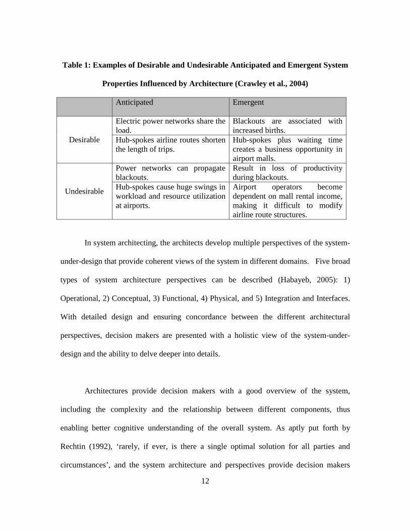
consequences that can be desirable or undesirable to the system. Crawley et al. (2004) in
their research on “The influence of Architecture in Engineering Systems” illustrated
some of the examples in emergent properties that are reproduced in Table 1.
12
Table 1: Examples of Desirable and Undesirable Anticipated and Emergent System
Properties Influenced by Architecture (Crawley et al., 2004)
Anticipated Emergent
Desirable
Electric power networks share the load.
Blackouts are associated with increased births.
Hub-spokes airline routes shorten the length of trips.
Hub-spokes plus waiting time creates a business opportunity in airport malls.
Undesirable
Power networks can propagate blackouts.
Result in loss of productivity during blackouts.
Hub-spokes cause huge swings in workload and resource utilization at airports.
Airport operators become dependent on mall rental income, making it difficult to modify airline route structures.
In system architecting, the architects develop multiple perspectives of the system-
under-design that provide coherent views of the system in different domains. Five broad
types of system architecture perspectives can be described (Habayeb, 2005): 1)
Operational, 2) Conceptual, 3) Functional, 4) Physical, and 5) Integration and Interfaces.
With detailed design and ensuring concordance between the different architectural
perspectives, decision makers are presented with a holistic view of the system-under-
design and the ability to delve deeper into details.
Architectures provide decision makers with a good overview of the system,
including the complexity and the relationship between different components, thus
enabling better cognitive understanding of the overall system. As aptly put forth by
Rechtin (1992), ‘rarely, if ever, is there a single optimal solution for all parties and
circumstances’, and the system architecture and perspectives provide decision makers
13
with the information required at the early stages of concept development for evaluation
and assessment.
DoDAF as Tool for Early Concept Evaluation in DoD
As stated in the preceding section, when effectively utilized, system architecting
provides system architects with a tool to enable assessments and achieve quantifiable
trade-studies. Similarly, the concept of system architecting can be employed in the
current DoD development and acquisition process to evaluate programs during early
Concept Evaluation. Recognizing this, the DoD already has a system architecting
framework, DoD Architecture Framework (DoDAF, 2009), in place. Before embarking
on EA for DoD projects, it is necessary for the system architects to have a good
understanding of DoDAF.
DoD Architecture Framework
DoDAF is the over-arching comprehensive framework and conceptual model that
prescribes a set of architectural artifacts in the development of architecture. It is data-
centric and emphasizes fit-for-purpose architectural development. The purpose of
DoDAF is to manage complexity by facilitating the ability of DoD decision makers to
make key decisions more effectively through organized information sharing across the
Department, Joint Capabilities Areas, Mission, Component, and Program boundaries.
DoDAF sets the common framework to standardize architectural descriptions and ensure
14
that these descriptions can be compared, related, understood, exchanged, and reused
across multiple stakeholders by employing common language and rules (DoDAF, 2009a).
Eight viewpoints are provided under DoDAF as described in DoDAF Volume 2
(DoDAF, 2009b):1) All Viewpoint provides the overarching perspective of the system-
under-design, including information such as scope, context, and vocabulary; 2)
Capability Viewpoint that provides perspective on the capability of the system; 3) Data
and Information Viewpoint provides the operational and business information
requirements and rules that are managed within and used as constraints on the
organizations business activities; 4) Operational Viewpoint describes the tasks and
activities, operational elements, and resource flow exchanges required to conduct
operations; 5) Project Viewpoint describes how programs, projects, portfolios, or
initiatives deliver capabilities, the organizations contributing to them, and the
dependencies between them; 6) Services Viewpoint describes services and their
interconnections providing or supporting DoD functions; 7) Standards Viewpoint
describes the set of rules governing the arrangement, interaction and interdependence of
parts or elements of the architectural description; and 8) Systems Viewpoint describes the
systems and interconnections providing for, or supporting, DoD functions. Together,
these viewpoints provide a comprehensive and complete description of the system-under-
design.
Central to these viewpoints are the set of artifacts that are defined under the Data
Meta-Model (DM2). With the transition to DoDAF v2.02, the framework shifted from a
15
product-centric process to a data-centric process, focusing on providing decision-making
data to the decision makers (DoDAF, 2010). In DoDAF v2.02, models based on DM2,
such as documents, spreadsheets, or other graphical representations, enable decision
makers to visualize architectural data (DoDAF, 2009a).
System Architecting—From Static Viewpoints to Dynamic Executable Models
With a better understanding of DoDAF, the literature review will now focus on
the current technology in developing dynamic executable mode for EA. It is therefore
necessary to understand the two difference between the two broad categories in system
architectures: 1) Static Architecture; and 2) Executable Architecture (EA).
Static Architecture can be defined as static views of the architecture based on the
development of static products, such as specification documents, drawings, and plans
while Executable Architecture can be defined as executable dynamic simulations that are
automatically or semi-automatically generated from architecture models or products as
defined by Hu et al (2014). In addition, Wang et al (2014) further deliberate that each EA
comprise three main components—1) Executable Model, 2) Execution Mechanism, and
3) Execution Process.
To better understand EA, it is necessary to first have an understanding of Model-
Based System Engineering (MBSE). MBSE is defined by INCOSE in “System
Engineering Vision 2020” (2007) as ‘the formalized application of modeling to support
16
system requirements, design, analysis, verification, and validation activities beginning in
the conceptual design phase and continuing throughout development and later life cycle
phases’. The introduction of MBSE also drives the development of executable
architecture through the creation of system models, as seen in the Model-Driven
Architecture (MDA) approach championed by the Object Management Group (Brown et
al., 2004, Pastor et al., 2007, Kleppe et al., 2003).
With the increasing complexity in the modern defense acquisition program, SA is
no longer sufficient to provide the level and depth of analysis required. In particular, the
relations and interactions between different nodes are difficult to define and model in a
static view, where the type of events, as well as the sequence in which these events occur,
has a big impact on system performance. In this regard, EA provides the capability for
system architects to include dynamic models and interactions in the architecture, thus
providing a more complete model across operational time and space.
Methodology for Implementing EA from Static Architecture
To achieve dynamic simulations based on the static architectural models, three
different methodologies can be implemented: 1) Develop software that simulates the
architectural models; 2) Import the models into simulations software; and 3) Direct
transformation of static architecture models into dynamic executable models. The
methodologies are summarized in Table 2 and further elaborated in the subsequent
paragraphs.
17
Table 2: Comparisons of Methodologies
Methodologies Pros Cons
Develop Simulation Software based on Static viewpoints
1. Flexibility in development.
2. Customizability to provide level of abstraction and user-interface
1. Interpretation Errors. 2. Longer lead time and
development cost. 3. Substantial re-
programming efforts may be incurred during changes.
Import models into simulation software
1. Built-in functionality for basic evaluation.
2. Less programming required.
1. Interpretation Errors. 2. Need for expert in
simulation software.
Direct Transformation of static architecture models into dynamic models
1. Reduce intermediate interpretation error.
2. Ease of introducing architectural variation.
1. Lack of flexibility. 2. Constrained by
Software.
Software Development. The system models are designed using modeling
languages, with rules and behaviors articulated in the diagrams. Similar to the
software system engineering process, these system models form the basis for
programmers to design executable codes (similar to Agile software development
process articulated by Larman (2004)). Here, the system interactions and
18
behaviors are implemented in software that are specifically customized to the
static models. The key benefits of this method are: 1) Flexibility for the
programmer to implement different aspects of the models, such as special rules
and relationships; and 2) Customizability to provide the level of abstraction and
user-interface required to enable better understanding of the trade-space, and for
effective communications between stakeholders. However, there are also several
disadvantages, namely: 1) Need for software programmers to interpret the static
models and design the software products, which can introduce interpretation
errors into the system where the software does not represent the static models
accurately; 2) Need for longer lead time and developmental cost in simulation
software development; and 3) Changes to the static models may results in
substantial re-programming efforts.
Use of Simulation Software. Another method to assess static models is to import
these models into simulation software packages, such as Arena or Simulink in
Matlab. Using simulation software, the architectural models and their attributes
are designed and simulations are carried out to obtain the results of the
architectural design. The key benefits of this method are: 1) Simulation software
packages often have stochastic functionality built-in to provide basic results
evaluation; and 2) Less programming is required as compared to developing a
software from scratch. Similarly, this method also has disadvantages, namely: 1)
Need for simulation programmers to interpret the static models and develop
19
equivalent models in the simulation software, hence the possibility of introducing
interpretation error, similar to that in software development; and 2) Need for
additional simulation software and experts who are able to effectively and
accurately implement the static models in the simulation software.
Direct Transformation of Static Model. In this method, the static models are
designed using software which then transforms them into dynamic executable
models. The main benefits for this method are: 1) No intermediate interpretation
and design is required by additional parties such as programmers, hence
minimizing interpretation errors; 2) Ease of introducing architectural variation
into the design, as changes to the static models can be transformed into executable
models directly. The main disadvantage for this method is the lack of flexibility in
the implementation of additional rules, which can only be implemented with
additional programming scripts into the EA software. The direct transformation of
the static models forms the basis of EA which are further elaborated in the next
sub-section. For example, the Enterprise software by Sparx and Innoslate are able
to perform this transformation.
Evaluation of Different Modeling Languages
DoDAF v2.02 provides system architects with a clearly defined framework and
viewpoints for the development of architectures. The use of models within DoDAF
further enables system architects to utilize MBSE techniques to implement executable
20
DoDAF architectures. To ensure that DoDAF Operational Views are accurately captured
in the modeling process, Bueno et al (2014) proposed an integrated methodology to build
an executable architecture based on the system dynamics of the Operational Views to
achieve concordance. With the emerging development in MBSE and EA, several
modeling languages have been introduced and extended to support the modeling and
simulation of system architecture. To effectively create an EA, there is a need to
accurately create architectural structures through the use of modeling language, and to
convert the static models into dynamic models using transformation methods. Here, the
following modeling languages and profiles are introduced and evaluated, namely: 1)
Unified Modeling Language (UML), 2) System Modeling Language (SysML) and 3)
Unified Profile for DoDAF/Ministry of Defense Architecture Framework (MoDAF)
(UPDM), for the development of DoDAF models. It is noted that while UPDM is not a
modeling language, it is a subset of UML that is developed specifically for DoDAF, and
therefore it is important to include UPDM in the evaluation.
a. Unified Modeling Language (UML): UML is a modeling language that
supports Object-Oriented Analysis and Design (OOAD) and is primarily used
in the area of software development (Larman, 2004). Currently in version 2.5,
UML enables architects to develop models in three major categories of model
elements, namely—1) Classifiers that describe a set of objects, 2) Events that
describe set of possible occurrences, and 3) Behaviors that describe a set of
possible executions (OMG UML, pg 12, 2015).
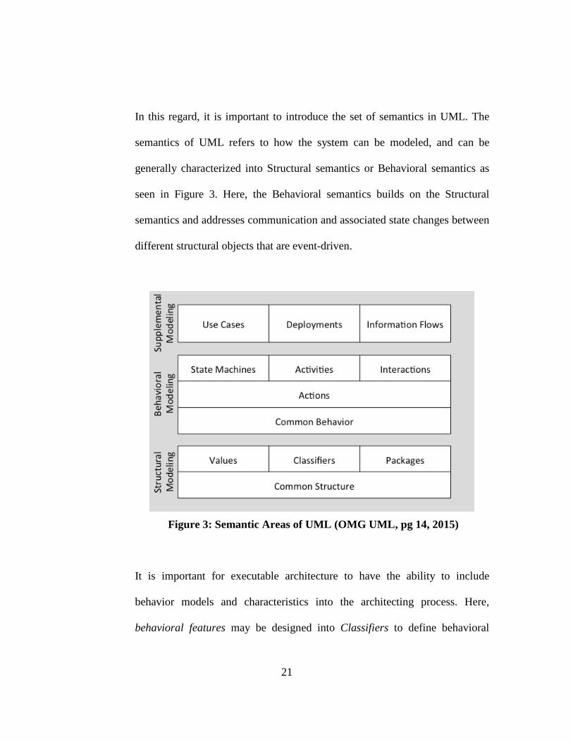
21
In this regard, it is important to introduce the set of semantics in UML. The
semantics of UML refers to how the system can be modeled, and can be
generally characterized into Structural semantics or Behavioral semantics as
seen in Figure 3. Here, the Behavioral semantics builds on the Structural
semantics and addresses communication and associated state changes between
different structural objects that are event-driven.
Figure 3: Semantic Areas of UML (OMG UML, pg 14, 2015)
It is important for executable architecture to have the ability to include
behavior models and characteristics into the architecting process. Here,
behavioral features may be designed into Classifiers to define behavioral
22
characteristics into an otherwise static model. With the use of suitable tools,
such as Enterprise Architect by Sparx System, these Behavior models can be
translated into an executable format that may be executed dynamically over
time, in accordance with the Events and triggers that occur, and hence provide
the architect with a dynamic view of the system-under-design (OMG UML,
2015).
To achieve common understanding in UML models, there is a need to develop
common standards, syntax, and semantics. The syntax in UML is achieved
through the Meta-Object Facility (MOF) framework that serves as the
platform-independent metadata management foundation for Model-driven
architecture (MDA) (OMG MOF, pg 5, 2015). The syntax determines how
UML models may be constructed, represented, and interchanged.
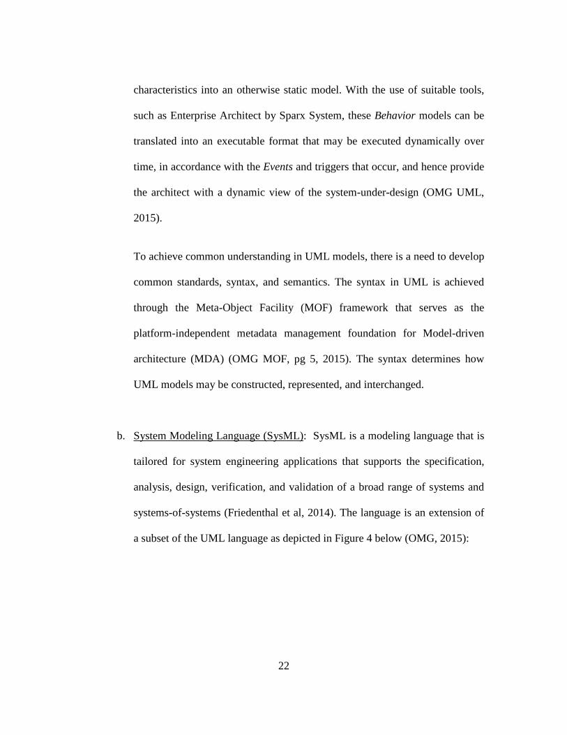
b. System Modeling Language (SysML): SysML is a modeling language that is
tailored for system engineering applications that supports the specification,
analysis, design, verification, and validation of a broad range of systems and
systems-of-systems (Friedenthal et al, 2014). The language is an extension of
a subset of the UML language as depicted in Figure 4 below (OMG, 2015):
23
Figure 4: Relationship between SysML and UML (OMG, 2015)
Similar to UML, SysML allows architects to create dynamic models through
the use of Behavior diagrams. In addition, with the modifications and new
diagrams, SysML is better equipped to enable EA. Some of the examples are:
1) Enabling rate of data flow to be specified between activities; 2) Introducing
Control Operators that are able to enable or disable other actions; and 3)
Supporting assignment of probabilities to activities (Balmelli, 2007). These
improvements directly improve SysML’s functionality to support EA.
c. UPDM (Unified Profile for DoDAF/MoDAF): UPDM is a visual modeling
standard that supports the development of architectures that comply with the
USA DoDAF and UK MODAF (OMG UPDM, 2010). It is an extension of
UML/SysML that is tailored to provide a consistent and standardized means
to describe DoDAF and MODAF architectures (Hause et all, 2010). This is an
important improvement in operationalizing UML/SysML in supporting
24
concept evaluation using EA for DoD related projects, since the models from
UPDM are aligned with DoDAF prescribed products (UPDM, 2012).
Specifically, UPDM is developed using a model-driven approach where
models conforming to DM2 specification are defined defined using UML
class models to enable data-centric architecture development. Since UPDM is
based on UML/SysML, it is also primarily a static modeling language that
will need to be transformed into an executable model.
Different Implementations for Transforming Static Models into Executable Models
It is important to note that modeling languages such as UML, SysML, and UPDM
are by themselves a modeling and diagramming language, and are not executable without
the use of additional processing or translation into EA. In addition, while UML and its
extensions serve as an effective tool for the development of static models for software
architecture, there are limitations in UML for EA due to the lack of informal execution
semantics (Wang, 2011) and the difficulty in achieving concordance between different
diagrams within UML (Wagenhals et al, 2009).
With the growing interest in creating EA, there are further efforts to develop a
methodology to transform these static models into executable dynamic models. In this
regard, two different methodologies are presented: 1) Model-driven Architecture; and 2)
Colored Petri-Nets.
25
a. Model-driven Architecture (MDA). MDA is an initiative introduced by OMG
to enable the development of executable software from static models. Here,
two terms are introduced—1) Platform-independent-model (PIM) is the static
model that describes the architecture of the system-under-design, and 2)
Platform-specific-model (PSM) that is executable in a specific platform (such
as Java).
Central to MDA is the set of standards: UML, MOF, Extensible Markup
Language (XML) Metadata Interchange (XMI) and Common Warehouse
Metamodel (CWM). Through the use of UML and MOF standards, UML-
based modeling languages (such as UML, SysML, and UPDM) can create
PIM with well-defined parameters that can be interpreted and automatically
transformed into PSM, which can then be executed as an EA. To achieve this,
a transformation pattern is first applied to the model to transform it to
software codes (such as C# or Java) (OMG MDA, 2014).
One example of MDA implementation can be found in executable and
translatable UML, also known as the XTUML, modeling language. X
TUML
combines a subset of UML graphical notation with executable semantic and
timing rules (Starr, 2002), and XTUML creates PIM that can be automatically
transformed into PSM, and have been tested and verified by Siljamaki et al
(2008) and Ciccozzi et al (2010). A study by Burden et al (2011) showed that
26
students do not need an extensive course in XTUML to be proficient in the
language. Other software tools also enable users to create executable models
using UML. For example, Sequence Diagrams, State-Machine Diagrams and
Activity Diagrams can be executed in Enterprise Architecture Software with
the use of additional Javascripts (Sparx, 2016).
b. Color Petri-Net: Color Petri-Net (CPN) is a very general discrete event
dynamical system model that is mathematically rigorous, executable, and
enables both simulation and analysis of properties (Wagenhals et al, 2009). To
achieve EA using CPN, it is necessary to transform the static models (such as
UML, SysML models) into executable models. For example, Liles (2008)
created the process for the auto-generation of an executable CPN model of an
architecture description that is DoDAF compliant using UML, specifically the
transformation of UML Activity Diagrams to create executable model of a
System-of-Systems; while Wang et al. (2008) translated SysML-based
specifications into CPN to achieve discrete-event simulation.
CPN utilizes the concept of typed tokens to represent objects within the
systems. The state of the system is determined by the distribution of tokens
over different nodes, and transitions represent actions within the system.
CPNs are well suited for modeling concurrent behavior of distributed systems
27
as multiple transitions are enabled and allow for the non-deterministic firing
of transition actions (Wang et al, 2015).
Introducing Life-cycle Modeling Language
In addition to the static and dynamic models derived from UML-based modeling
language, there is also a relative new language that is designed specifically for systems
engineering—Life-cycle Modeling Language (LML) (LML, 2015). LML focuses on the
use of easy to understand ontology to allow system architects to model complex
interrelationship between system components, as well as artifacts such as schedules and
risk management plans. The basis for LML formulation is the Entity, Relationship, and
Attribute (ERA) meta-model. By using everyday language in its implementation, LML is
easy to understand and communicate between stakeholders and the design team.
With pre-defined Actions and Input/Output entities, LML enables system
architects to develop EA using Action Diagrams. The Action Diagrams represents the
functional sequencing of Actions along with the data flow provided by the Input/Output
entities. The Actions such as “OR”, “SYNC” or “LOOP” are predefined and allow LML
to be executable in accordance with the rules associated with Actions and the conditions
in the Input/Output entities. Innoslate, a web-based LML system, allows users to create
LML diagrams that can be executed. In addition, Innoslate has incorporated DM2 into the
LML ontology, and hence users are able to create artifacts in accordance with the
specification in DM2 as well as to create other DoDAF products. However, being a
28
relatively new language, LML does not have the full range and depth of modeling
capabilities as seen in more matured languages such as UML/SysML.
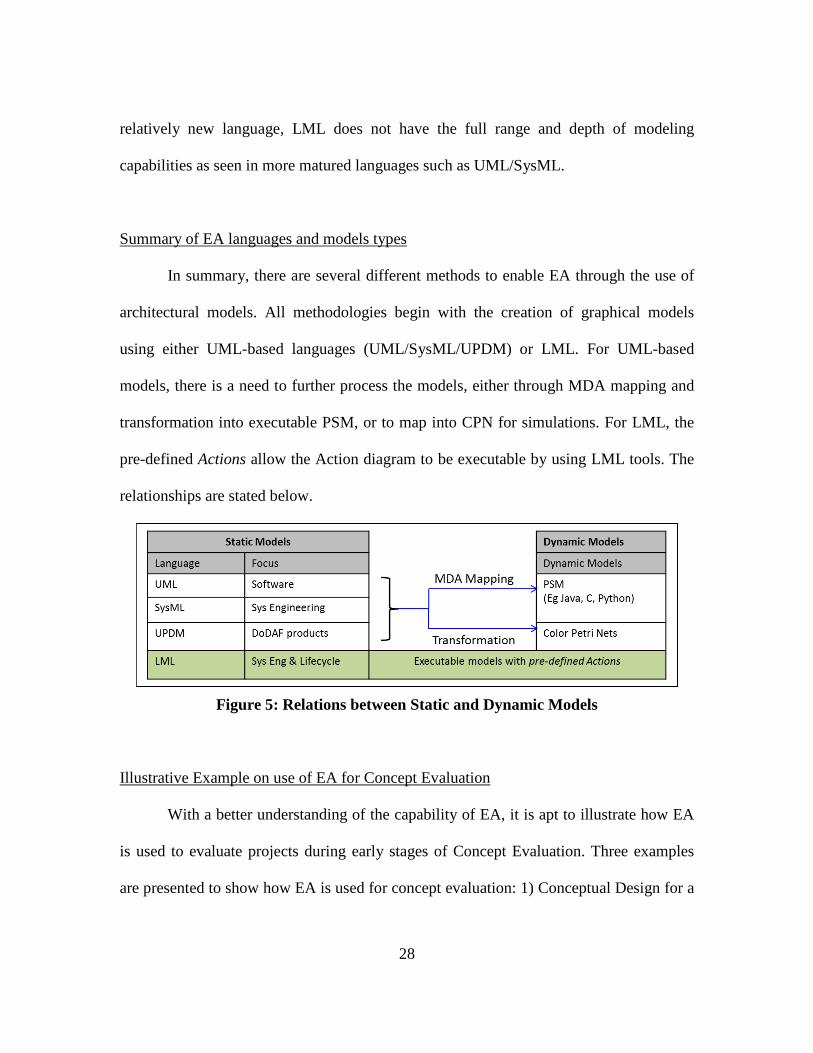
Summary of EA languages and models types
In summary, there are several different methods to enable EA through the use of
architectural models. All methodologies begin with the creation of graphical models
using either UML-based languages (UML/SysML/UPDM) or LML. For UML-based
models, there is a need to further process the models, either through MDA mapping and
transformation into executable PSM, or to map into CPN for simulations. For LML, the
pre-defined Actions allow the Action diagram to be executable by using LML tools. The
relationships are stated below.
Figure 5: Relations between Static and Dynamic Models
Illustrative Example on use of EA for Concept Evaluation
With a better understanding of the capability of EA, it is apt to illustrate how EA
is used to evaluate projects during early stages of Concept Evaluation. Three examples
are presented to show how EA is used for concept evaluation: 1) Conceptual Design for a
29
manned mission to Mars (Colombi et al., 2015); 2) Assessment of the Weapon Born
Battle Damage Assessment (WBBDA) for Time Sensitive Effect Operations (TSEO)
(Rodriguez, 2005); and 3) Extended Sequence Modeling (ESM) for Capability Review
and Risk Assessment (CRRA) (Mastro et al, 2009).
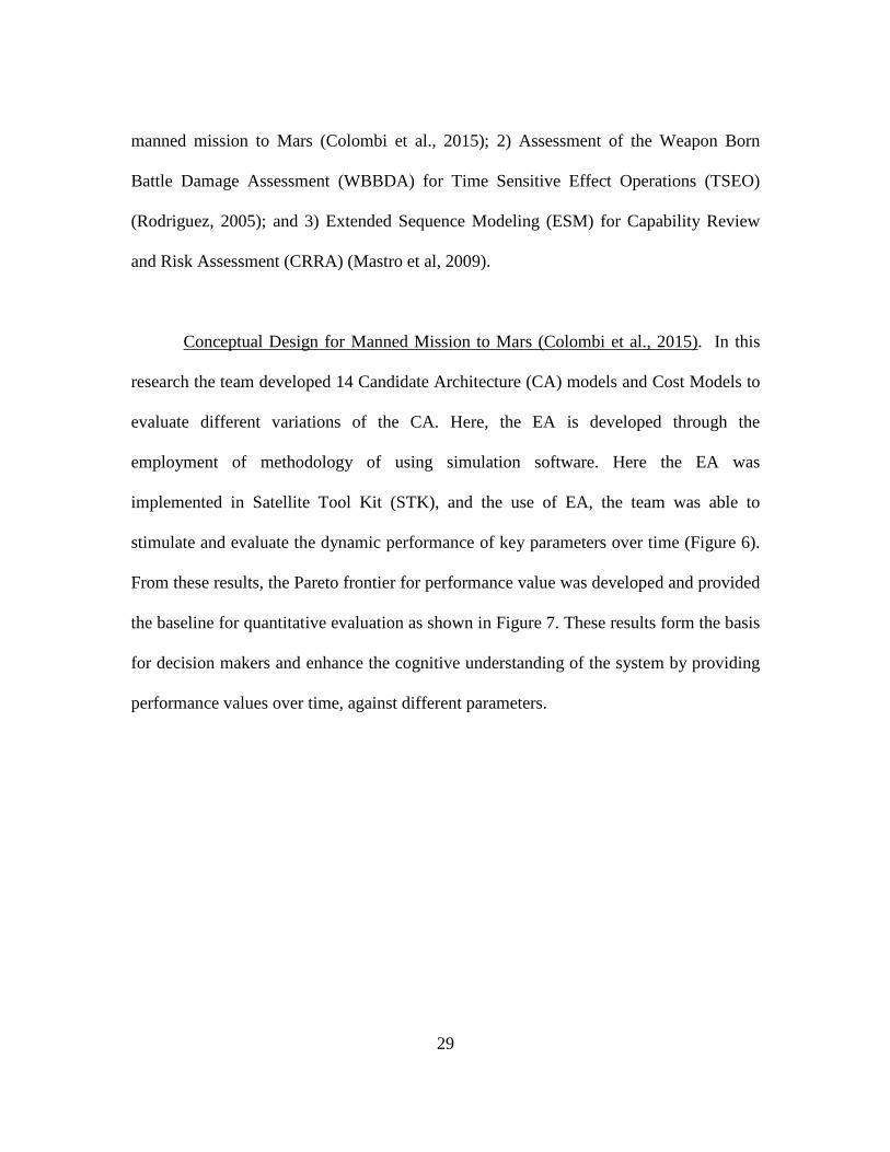
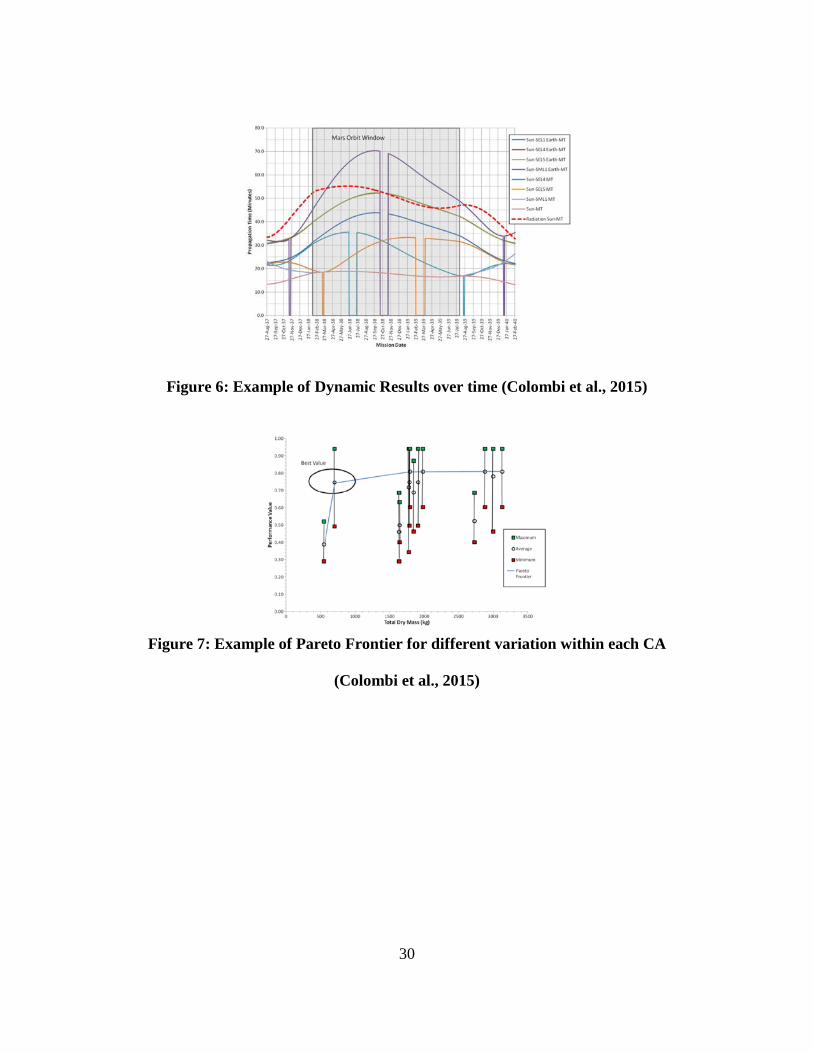
Conceptual Design for Manned Mission to Mars (Colombi et al., 2015). In this
research the team developed 14 Candidate Architecture (CA) models and Cost Models to
evaluate different variations of the CA. Here, the EA is developed through the
employment of methodology of using simulation software. Here the EA was
implemented in Satellite Tool Kit (STK), and the use of EA, the team was able to
stimulate and evaluate the dynamic performance of key parameters over time (Figure 6).
From these results, the Pareto frontier for performance value was developed and provided
the baseline for quantitative evaluation as shown in Figure 7. These results form the basis
for decision makers and enhance the cognitive understanding of the system by providing
performance values over time, against different parameters.
30
Figure 6: Example of Dynamic Results over time (Colombi et al., 2015)
Figure 7: Example of Pareto Frontier for different variation within each CA
(Colombi et al., 2015)
31
Assessment of WBBDA (Rodriguez, 2005). In this research, the team utilized EA
to compare the effectiveness of WBBDA in TSEO. Specifically, methodology of direct
transformation of static model was used. Here, the different variants of the system,
utilizing different warheads and WBBDA combinations were implemented in CoreTM
software and Monte Carlo simulations were done. From the results, the team was able to
conclude that a low lethality warhead system would benefit from the implementation of
WBBDA, and provide recommendation for future analysis.
ESM in CRRA (Mastro et al, 2009). As part of this research, the team introduced
the concept of ESM to improve the Process Sequence Modeling in the CRRA process.
Unlike PSM which employs a binary result (pass or fail) in the activity models, ESM
allows the practitioner to incorporate Probability Distribution Function (PDF) in the
modeling process. Specifically, ESM can be defined as a type of executable dynamic
architecture that has been specifically developed to analyze the CRRA, and provide
CRRA practitioners with the ability to evaluate capabilities by varying the activities of
interest or their dependencies. To implement the EA, the team used the methodology of
software development, where the team developed Matlab codes for the dynamic models.
The research team then implemented the ESM technique to a portion of an Agile Combat
Support PSM in support of the 2009 CRRA and provided effects of dependencies such as
number of people required in support of surge operations.
32
Conclusion
From the literature review, it is shown that executable architecting has the
potential to provide program offices with the capability to assess and evaluate projects
during the early Concept Development stage. This was further illustrated using the work
done on concept evaluation of manned-mission to Mars. In addition, with the continuous
refinement of DoDAF and improvement in the modeling languages, system architects are
better equipped to develop architectures for DoDAF related systems.
33
III. Methodology
Chapter Overview
The purpose of this thesis is to evaluate the effect of architectural variance during
the early concept development phase for the implementation of a multi-tiered UAS SoS
for tactical ISR and dynamic strike operations to destroy Theater Ballistics Missiles
(TBM) launchers. Modified from the Architectural-Based Evaluation Process (ABEP)
(Dietrichs et al, 2006), the proposed methodology is developed from the perspective of
the development team, after the team receives the Concept of Operations (CONOPS) and
user’s requirements. This methodology aims to evaluate different architectural variations
based on implementation of the CONOPS and the effectiveness in fulfilling the user’s
requirement, and provide the users with a quantitative assessment of the different
variations.
The methodology will begin with an overview of the operational need and
scenario, followed by a summary of a fictitious CONOPS that envisage how UAS from
different tiers could be employed cooperatively to locate and strike TBM launchers. This
is followed by the development of high level DoDAF Operational Views of the system.
Next, the architectural variants are identified, and an assessment is made to determine
which user requirements and corresponding MOEs will be affected by the architectural
variants. Lastly, the EA models are designed to simulate the different variants, and the
results are evaluated based on the identified MOEs. The architectural products and EA
are designed and implemented using Innoslate (Innoslate, 2012), a web-based EA tool.
34
Overview of Research Methodology
The proposed research methodology is a six-step process, namely: 1) Understand
and analyze Scope and Operational Use for system-under-design; 2) Identify key user
requirements and MOEs; 3) Develop high level DoDAF architectural products; 4)
Identify architectural variants for evaluation; 5) Develop simulation scenario and EA
models; and finally 6) Simulate and conduct data analysis.
Step 1: Understand and analyze Scope and Operational Use for system-under-
design. To effectively answer the research questions, it is necessary for the
development team to have a comprehensive understanding of how the System will
be deployed and operated by the users. This is achieved by understanding the
operational need, and the CONOPS to identify key design parameters and the key
user requirements.
Step 2: Identify key user requirements and MOEs. Following the analysis, the
key user requirements are further developed into quantifiable MOEs. For a more
effective comparison between the results of the different variants, the MOEs are
weighted through the use of the Analytic Hierarchy Process (AHP) to better
evaluate the effectiveness, based on the relative importance of each MOE.
Step 3: Develop high level DoDAF architectural products. Next, to ensure that
the CONOPS are understood correctly, the following architectural products are
35
developed and presented to the users. As this is an early concept evaluation, the
focus is on developing high level All Views and Operational Views, namely AV-
1 (Overview and Summary Information), OV-1 (High Level Operational Concept
Graphic), OV-2 (Operational Resource Flow Description), OV-5 (Operational
Activity Decomposition Tree and Operational Activity Model), and OV-6a
(Operational Rules Model). These products aid communication and ensure that
both development team and users have the same understanding for the system-
under-design.
Step 4: Identify architectural variants for evaluation. Next, based on the OVs
developed, the development team will identify possible architectural variants.
These architectural variants must fulfill the CONOPS as stipulated by the users,
and will drive design parameters that impact the effectiveness of the system-
under-design. To determine the effect, the operational activities are analyzed and
the effect of respective variants on each activity are identified.
Step 5: Develop simulation scenario and EA models. Based on the CONOPS, a
simulation scenario is developed that depicts how the system-under-design will be
operationalized. Next, the different architectural variants are incorporated into the
EA models based on OV-5b, using the results of the analysis from step 4. For this
research thesis, the EA models are developed using Innoslate.
36
Step 6: Data Collection and Analysis. For the results to be statistically
significant, Monte Carlo simulation will be executed, with at least 30 runs to be
completed. For the purpose of this research, the Monte Carlo simulation will be
executed with 50 runs. From the results, each variant is scored based on the MOE
weightings (from Step 4), and a Pareto Frontier can be charted.
Implementation of Methodology
Using the proposed methodology described in the preceding section, the different
architectural variants of the Multi-tiered UAS SoS is evaluated. The following sections
detail the implementation of each of the steps in the methodology.
Step 1: Understand and analyse Scope and Operational Use for system-under-design
The System-under-design is a SoS of multi-tiered UAS that will be deployed for
ISR and dynamic strike on Theater Ballistics Missile (TBM) launchers. The scope and
use for the system will be driven by the operational need and CONOPS. To further
expand on the system-deployment and understanding, the use-cases for the system are
developed according to the CONOPS. The CONOPS was developed as part of a course
requirement by four authors, including the author of this thesis.
Operational Need. Rapid improvements of TBM technology and increases in
weapons proliferation to non-allied nations have resulted in new and constantly changing
threats to friendly forces. The high accuracy of many TBM systems allow them to inflict
37
serious damages from significant stand-off distances, even when the missiles are armed
with only conventional warheads. To further compound the problem, TBM launchers
employ a shoot-and-scoot technique which makes counter-TBM operations challenging.
To address this threat, the military needs to have a capability that can preemptively seek
and destroy TBM launchers. This multi-tiered UAS SoS provides the capability to
maintain persistent situation awareness over a designated area to search and locate
possible TBM launchers and dynamically target and strike these TBM launchers with
minimal cost or risk to personnel.
CONOPS Overview. The multi-tiered UAS SoS focuses on the efficient
employment of different groups of UAS to maintain persistent situational awareness over
the Area of Operations (AO), to seek and identify possible TBM launchers, and to
dynamically direct targeting and strike operations. It leverages the capabilities of
different groups of UAS and sensor systems to achieve a system capable of optimizing
UAS employment for mission effectiveness, while minimizing operational cost and risk.
Specifically, the multi-tiered UAS SoS will need to employ cooperative control among
various UAS groups in the AO to assign roles and plan safe routes for ingress and egress.
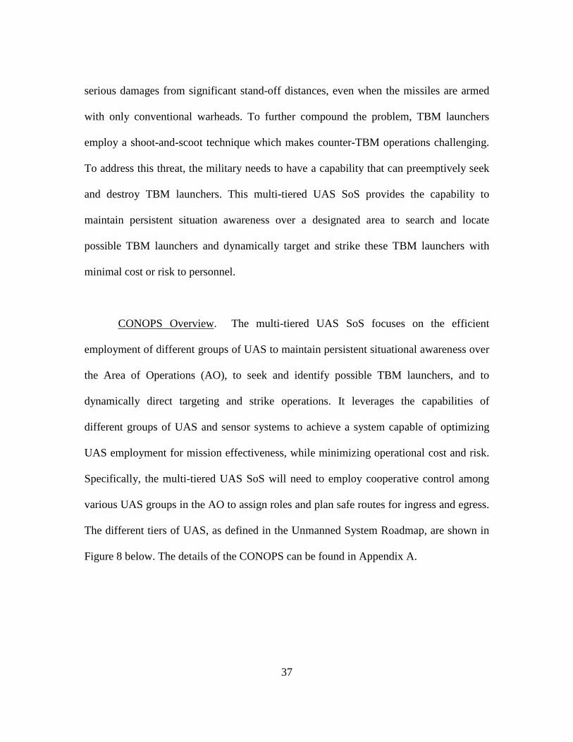
The different tiers of UAS, as defined in the Unmanned System Roadmap, are shown in
Figure 8 below. The details of the CONOPS can be found in Appendix A.
38
Figure 8: Classification of Different UAS tiers
a. Larger tiers UASs (Group 4 and 5):
i. Persistent ISR. The larger tiers of UASs have the greatest range,
endurance, airspeed, and altitude capabilities in the family of UAS. As
such, these UAS are typically employed to conduct persistent ISR over
the AO. They will be equipped with the necessary sensors to identify
possible Surface-to-Air (SAM) sites and possible TBM launchers in
the AO.
39
ii. Dynamic Strike. These groups of UAS are also capable of carrying
kinetic weapons, and could be loaded with the necessary munitions to
provide a dynamic strike capability.
b. Smaller tiers UASs (Group 1 and 2):
i. Target Verification. The smaller UAS groups have a smaller footprint
and are used for target verification and can be equipped with
Automatic Target Recognition (ATR) software to determine phases of
TBM launcher deployment.
ii. Battle Damage Assessment (BDA). These UAS groups will also be
used to perform BDA after the conclusion of the dynamic strike to
confirm mission success.
Use-Case: The Use Case diagram and the terse use-case of the system is as
shown in Figure 9, and Table 3 describe this diagram in details:
40
Table 3: Terse Use Cases
No Name Terse Use Case Write-up
UC 2.1 Find TBM
Site
The Mission Commander inputs mission parameters into System. The
System identifies available ISR UAS and assigns ISR UAS to find
TBM Site. ISR UAS continues loiter above AO and uses sensor data
Figure 9: Use Case Diagram
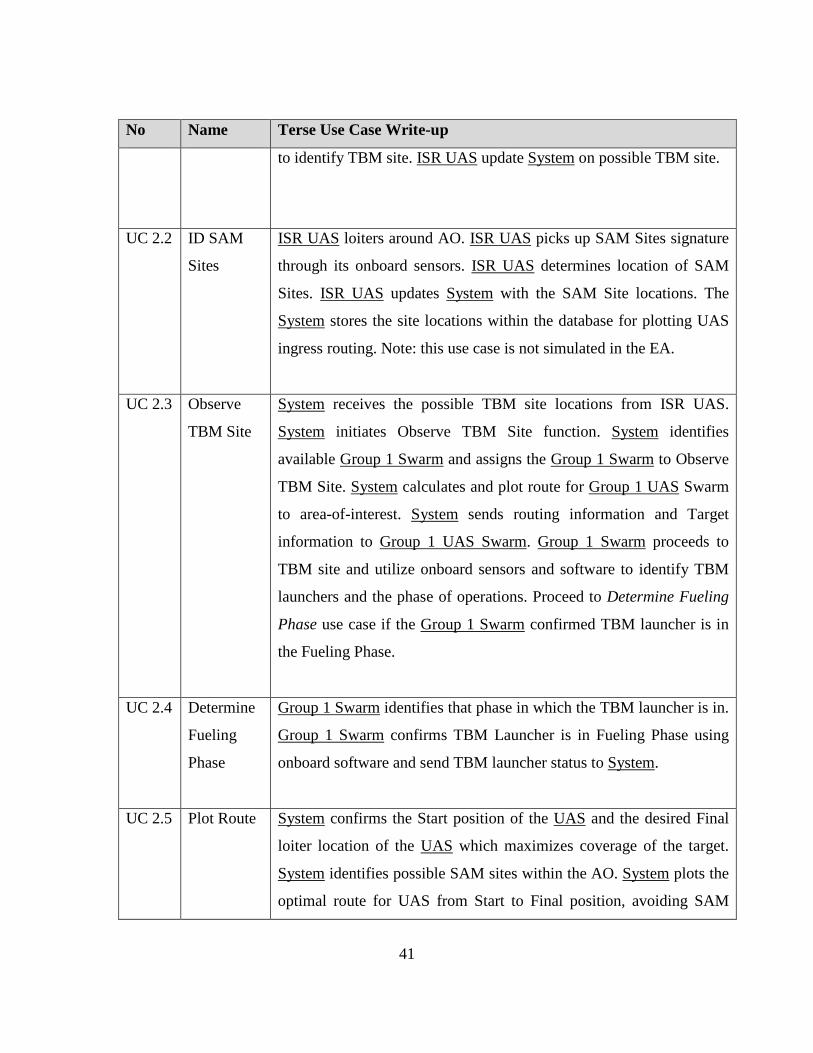
41
No Name Terse Use Case Write-up
to identify TBM site. ISR UAS update System on possible TBM site.
UC 2.2 ID SAM
Sites
ISR UAS loiters around AO. ISR UAS picks up SAM Sites signature
through its onboard sensors. ISR UAS determines location of SAM
Sites. ISR UAS updates System with the SAM Site locations. The
System stores the site locations within the database for plotting UAS
ingress routing. Note: this use case is not simulated in the EA.
UC 2.3 Observe
TBM Site
System receives the possible TBM site locations from ISR UAS.
System initiates Observe TBM Site function. System identifies
available Group 1 Swarm and assigns the Group 1 Swarm to Observe
TBM Site. System calculates and plot route for Group 1 UAS Swarm
to area-of-interest. System sends routing information and Target
information to Group 1 UAS Swarm. Group 1 Swarm proceeds to
TBM site and utilize onboard sensors and software to identify TBM
launchers and the phase of operations. Proceed to Determine Fueling
Phase use case if the Group 1 Swarm confirmed TBM launcher is in
the Fueling Phase.
UC 2.4 Determine
Fueling
Phase
Group 1 Swarm identifies that phase in which the TBM launcher is in.
Group 1 Swarm confirms TBM Launcher is in Fueling Phase using
onboard software and send TBM launcher status to System.
UC 2.5 Plot Route System confirms the Start position of the UAS and the desired Final
loiter location of the UAS which maximizes coverage of the target.
System identifies possible SAM sites within the AO. System plots the
optimal route for UAS from Start to Final position, avoiding SAM
42
No Name Terse Use Case Write-up
sites. System transmits flight path to the respective UAS.
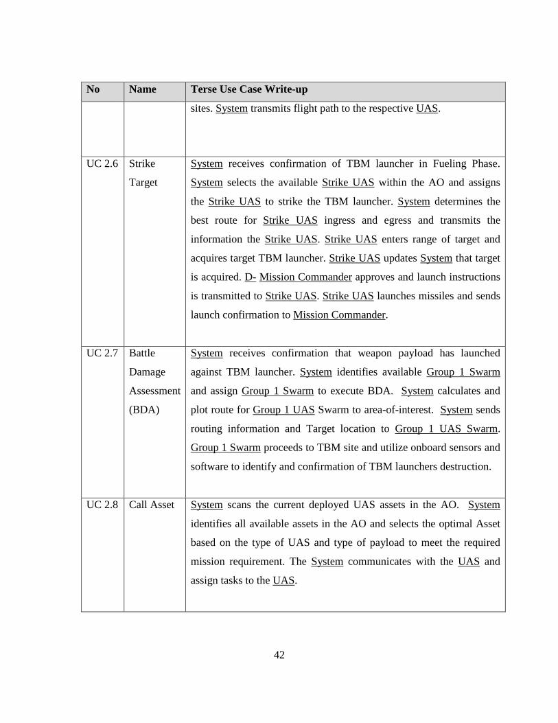
UC 2.6 Strike
Target
System receives confirmation of TBM launcher in Fueling Phase.
System selects the available Strike UAS within the AO and assigns
the Strike UAS to strike the TBM launcher. System determines the
best route for Strike UAS ingress and egress and transmits the
information the Strike UAS. Strike UAS enters range of target and
acquires target TBM launcher. Strike UAS updates System that target
is acquired. D- Mission Commander approves and launch instructions
is transmitted to Strike UAS. Strike UAS launches missiles and sends
launch confirmation to Mission Commander.
UC 2.7 Battle
Damage
Assessment
(BDA)
System receives confirmation that weapon payload has launched
against TBM launcher. System identifies available Group 1 Swarm
and assign Group 1 Swarm to execute BDA. System calculates and
plot route for Group 1 UAS Swarm to area-of-interest. System sends
routing information and Target location to Group 1 UAS Swarm.
Group 1 Swarm proceeds to TBM site and utilize onboard sensors and
software to identify and confirmation of TBM launchers destruction.
UC 2.8 Call Asset System scans the current deployed UAS assets in the AO. System
identifies all available assets in the AO and selects the optimal Asset
based on the type of UAS and type of payload to meet the required
mission requirement. The System communicates with the UAS and
assign tasks to the UAS.
43
No Name Terse Use Case Write-up
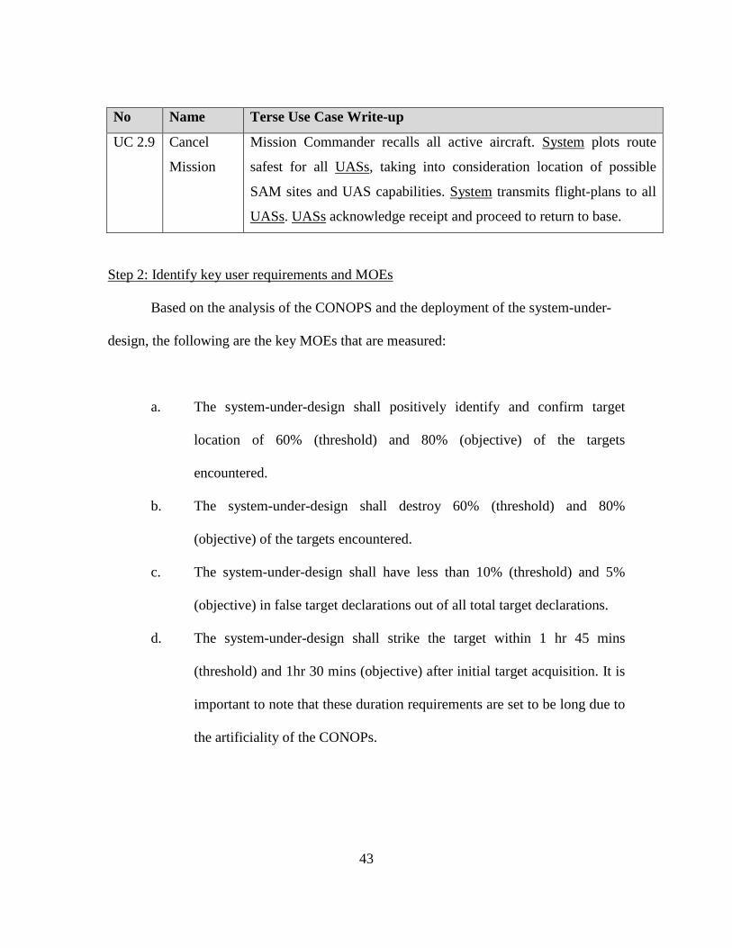
UC 2.9 Cancel
Mission
Mission Commander recalls all active aircraft. System plots route
safest for all UASs, taking into consideration location of possible
SAM sites and UAS capabilities. System transmits flight-plans to all
UASs. UASs acknowledge receipt and proceed to return to base.
Step 2: Identify key user requirements and MOEs
Based on the analysis of the CONOPS and the deployment of the system-under-
design, the following are the key MOEs that are measured:
a. The system-under-design shall positively identify and confirm target
location of 60% (threshold) and 80% (objective) of the targets
encountered.
b. The system-under-design shall destroy 60% (threshold) and 80%
(objective) of the targets encountered.
c. The system-under-design shall have less than 10% (threshold) and 5%
(objective) in false target declarations out of all total target declarations.
d. The system-under-design shall strike the target within 1 hr 45 mins
(threshold) and 1hr 30 mins (objective) after initial target acquisition. It is
important to note that these duration requirements are set to be long due to
the artificiality of the CONOPs.
44
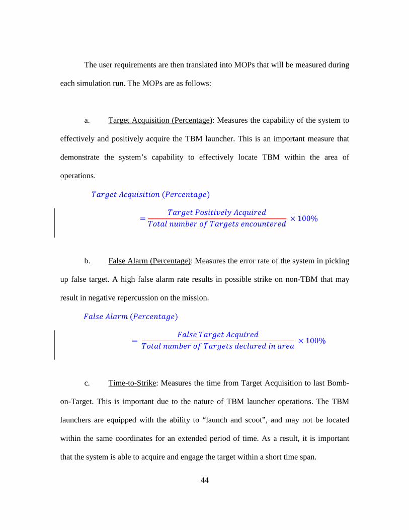
The user requirements are then translated into MOPs that will be measured during
each simulation run. The MOPs are as follows:
a. Target Acquisition (Percentage): Measures the capability of the system to
effectively and positively acquire the TBM launcher. This is an important measure that
demonstrate the system’s capability to effectively locate TBM within the area of
operations.
𝑇𝑇𝑇𝑇𝑇𝑇𝑇𝑇𝑇𝑇𝑇𝑇 𝐴𝐴𝐴𝐴𝐴𝐴𝐴𝐴𝑖𝑖𝑖𝑖𝑖𝑖𝑇𝑇𝑖𝑖𝑖𝑖𝑖𝑖 (𝑃𝑃𝑇𝑇𝑇𝑇𝐴𝐴𝑇𝑇𝑖𝑖𝑇𝑇𝑇𝑇𝑇𝑇𝑇𝑇)
=𝑇𝑇𝑇𝑇𝑇𝑇𝑇𝑇𝑇𝑇𝑇𝑇 𝑃𝑃𝑖𝑖𝑖𝑖𝑖𝑖𝑇𝑇𝑖𝑖𝑃𝑃𝑇𝑇𝑃𝑃𝑃𝑃 𝐴𝐴𝐴𝐴𝐴𝐴𝐴𝐴𝑖𝑖𝑇𝑇𝑇𝑇𝐴𝐴
𝑇𝑇𝑖𝑖𝑇𝑇𝑇𝑇𝑃𝑃 𝑖𝑖𝐴𝐴𝑛𝑛𝑛𝑛𝑇𝑇𝑇𝑇 𝑖𝑖𝑜𝑜 𝑇𝑇𝑇𝑇𝑇𝑇𝑇𝑇𝑇𝑇𝑇𝑇𝑖𝑖 𝑇𝑇𝑖𝑖𝐴𝐴𝑖𝑖𝐴𝐴𝑖𝑖𝑇𝑇𝑇𝑇𝑇𝑇𝑇𝑇𝐴𝐴 × 100%
b. False Alarm (Percentage): Measures the error rate of the system in picking
up false target. A high false alarm rate results in possible strike on non-TBM that may
result in negative repercussion on the mission.
𝐹𝐹𝑇𝑇𝑃𝑃𝑖𝑖𝑇𝑇 𝐴𝐴𝑃𝑃𝑇𝑇𝑇𝑇𝑛𝑛 (𝑃𝑃𝑇𝑇𝑇𝑇𝐴𝐴𝑇𝑇𝑖𝑖𝑇𝑇𝑇𝑇𝑇𝑇𝑇𝑇)
= 𝐹𝐹𝑇𝑇𝑃𝑃𝑖𝑖𝑇𝑇 𝑇𝑇𝑇𝑇𝑇𝑇𝑇𝑇𝑇𝑇𝑇𝑇 𝐴𝐴𝐴𝐴𝐴𝐴𝐴𝐴𝑖𝑖𝑇𝑇𝑇𝑇𝐴𝐴
𝑇𝑇𝑖𝑖𝑇𝑇𝑇𝑇𝑃𝑃 𝑖𝑖𝐴𝐴𝑛𝑛𝑛𝑛𝑇𝑇𝑇𝑇 𝑖𝑖𝑜𝑜 𝑇𝑇𝑇𝑇𝑇𝑇𝑇𝑇𝑇𝑇𝑇𝑇𝑖𝑖 𝐴𝐴𝑇𝑇𝐴𝐴𝑃𝑃𝑇𝑇𝑇𝑇𝑇𝑇𝐴𝐴 𝑖𝑖𝑖𝑖 𝑇𝑇𝑇𝑇𝑇𝑇𝑇𝑇 × 100%
c. Time-to-Strike: Measures the time from Target Acquisition to last Bomb-
on-Target. This is important due to the nature of TBM launcher operations. The TBM
launchers are equipped with the ability to “launch and scoot”, and may not be located
within the same coordinates for an extended period of time. As a result, it is important
that the system is able to acquire and engage the target within a short time span.
45
𝑇𝑇𝑖𝑖𝑛𝑛𝑇𝑇 𝑇𝑇𝑖𝑖 𝑆𝑆𝑇𝑇𝑇𝑇𝑖𝑖𝑆𝑆𝑇𝑇 = 𝐵𝐵𝑖𝑖𝑛𝑛𝑛𝑛 𝐿𝐿𝑇𝑇𝐴𝐴𝑖𝑖𝐴𝐴ℎ𝑇𝑇𝐴𝐴 𝑇𝑇𝑖𝑖𝑛𝑛𝑇𝑇 − 𝑇𝑇𝑇𝑇𝑇𝑇𝑇𝑇𝑇𝑇𝑇𝑇 𝐴𝐴𝐴𝐴𝐴𝐴𝐴𝐴𝑖𝑖𝑖𝑖𝑇𝑇𝑖𝑖𝑖𝑖𝑖𝑖 𝑇𝑇𝑖𝑖𝑛𝑛𝑇𝑇
d. Target Destruction (Percentage): Measures the total number of confirmed
targets that are positively destroyed. This MOP evaluates the overall capability of the
system in achieving its user’s requirement in TBM launcher destruction.
𝑇𝑇𝑇𝑇𝑇𝑇𝑇𝑇𝑇𝑇𝑇𝑇 𝐷𝐷𝑇𝑇𝑖𝑖𝑇𝑇𝑇𝑇𝐴𝐴𝐴𝐴𝑇𝑇𝑖𝑖𝑖𝑖𝑖𝑖 (𝑃𝑃𝑇𝑇𝑇𝑇𝐴𝐴𝑇𝑇𝑖𝑖𝑇𝑇𝑇𝑇𝑇𝑇𝑇𝑇)
=𝑇𝑇𝑇𝑇𝑇𝑇𝑇𝑇𝑇𝑇𝑇𝑇 𝐷𝐷𝑇𝑇𝑖𝑖𝑇𝑇𝑇𝑇𝑖𝑖𝑃𝑃𝑇𝑇𝐴𝐴
𝑇𝑇𝑖𝑖𝑇𝑇𝑇𝑇𝑃𝑃 𝑖𝑖𝐴𝐴𝑛𝑛𝑛𝑛𝑇𝑇𝑇𝑇 𝑖𝑖𝑜𝑜 𝑇𝑇𝑇𝑇𝑇𝑇𝑇𝑇𝑇𝑇𝑇𝑇𝑖𝑖 𝑇𝑇𝑖𝑖𝐴𝐴𝑖𝑖𝐴𝐴𝑖𝑖𝑇𝑇𝑇𝑇𝑇𝑇𝑇𝑇𝐴𝐴 × 100%
The MOPs will be tracked and pairwise comparison will be carried out. Next, the
Objective Hierarchy Process (OHP) is used to assign weights to each of the MOPs, and
an overall weighted score will be given for each variant based on the aggregated results.
Step 3: Develop High level DoDAF architectural products
Based on the analysis and the required MOEs, the following DoDAF architectural
products are developed—1) All-View 1 (AV-1), 2) Operational View 1 (OV-1), 3)
Operational View 2 (OV-2), 4) Operational View 5 (OV-5), Operational View 6 (OV-6)
and 5) Logical Data View (DIV-2). Similar to the CONOPS, the AV-1 and OV-1 were
developed as part of a System Architecting course requirement.
AV-1: The AV-1, derived from the CONOPS, provides an overview of the
system-under-design. In addition, the AV-1 lists the architectural products that will be
46
developed based on the requirement of the thesis investigation. The detailed AV-1 is
found in Appendix B.
OV-1: The OV-1 is a pictorial depiction of the system-under-design and serves as
an important visual communication tools to aid understanding between stakeholders. The
OV-1 for the system is as shown in Figure 10. Specifically, the OV-1 shows the linkage
and command links between the Command Post to the different tiers of UAS, and the
sequence of operations leading to the strike of the TBM launchers.
OV-2: The OV-2 provides the high level summary of the resource flow between
the different entities of the Multi-tiered UAS SoS. The key entities are—1) Decision
Makers (Manual or autonomous), 2) ISR UAS, 3) Surveil UAS, 4) Strike UAS, and 5)
BDA UAS. The key resource flows are information flows between the Decision Makers
and the different UAS tiers, specifically Mission Parameters and Command instructions
from the Decision Makers and telemetry and video data from the UAS. In addition, it is
noted that the Information Data Cloud is implemented as a logic node, and not a physical
node. The diagram is illustrated in Figure 11.
OV-5a: The OV-5a details the key activities in the Multi-tiered UAS SoS. The
key Activities can be distinctly demarcated into six broad categories, namely—1) ISR
UAS Operational Activities, 2) Surveil UAS Operational Activities, 3) Strike UAS
Operational Activities, 4) BDA UAS Operational Activities, 5) Decision Making
47
Activities, and 6) Monitoring Activities. The OV-5a focuses on the activities executed by
the different sub-system and hence may appear to be highly redundant. However, it is
necessary as it forms the foundation for OV-5b. The OV-5a is illustrated in Figure 12.
OV-5b: The OV-5b details the flow of the activities and how the different entities
operate within the multi-tiered UAS SoS. This is represented through the use of swim-
lanes in the diagram, which activities associated to the particular entity appearing on its
specific swim-lane. In addition, the OV-5b forms the foundation for the construction of
EA, based on the characteristic and logic flow between the different activities. The OV-
5b is illustrated in Figure 13.
OV-6a: The OV-6a details the operational rules for the key activities nodes in the
activity flow diagram, OV-5b. These rules are essential for the development of the EA as
they define the operational constraints of the system and the rules for the interaction
between different activities nodes. The details are illustrated in Table 4 below.
DIV-2: The DIV-2 details the relationship between different assets and the flow
of information between different assets. In particular, the DIV-2 focuses on establishing
the data model and the detailed flow of data between different entities. The details are
illustrated in Figure 14.
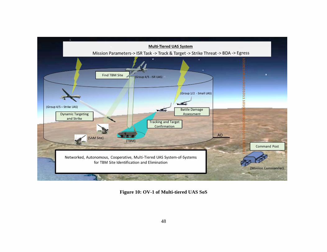
48
Figure 10: OV-1 of Multi-tiered UAS SoS
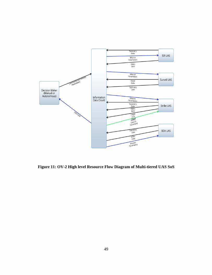
49
Figure 11: OV-2 High level Resource Flow Diagram of Multi-tiered UAS SoS
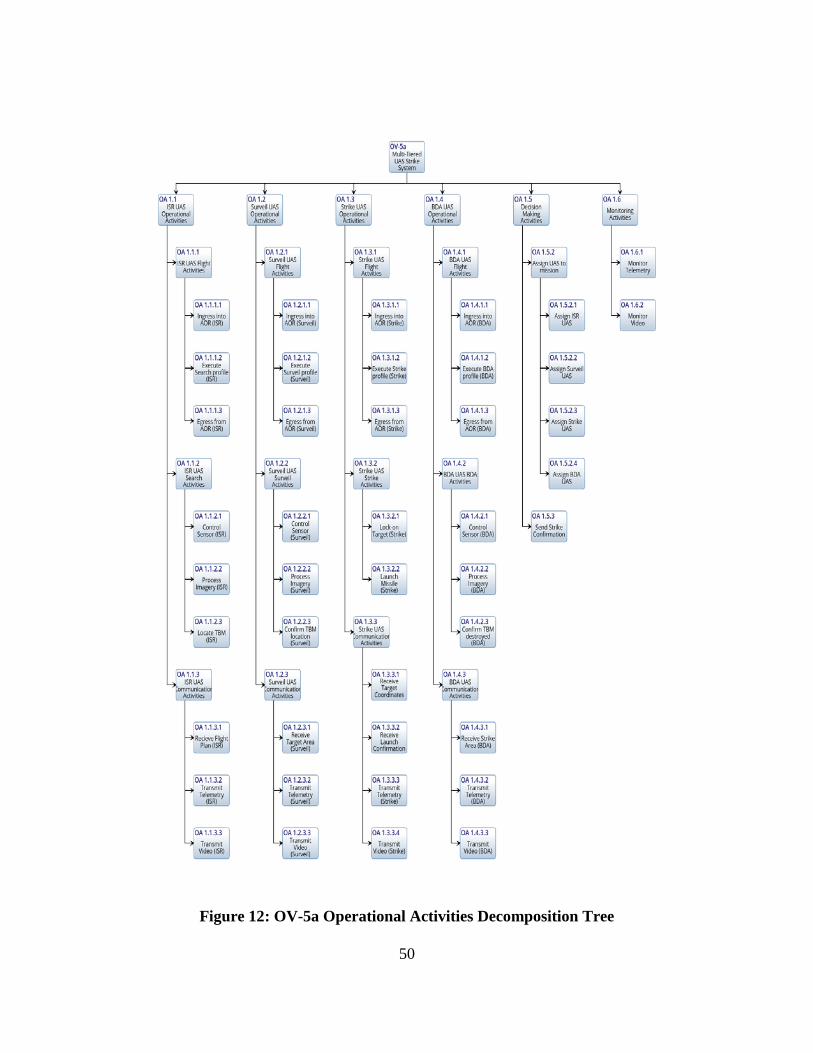
50
Figure 12: OV-5a Operational Activities Decomposition Tree
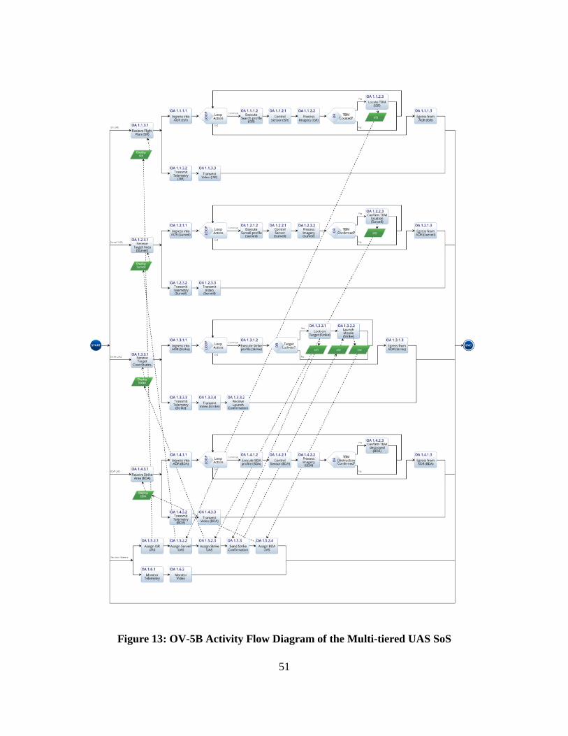
51
Figure 13: OV-5B Activity Flow Diagram of the Multi-tiered UAS SoS
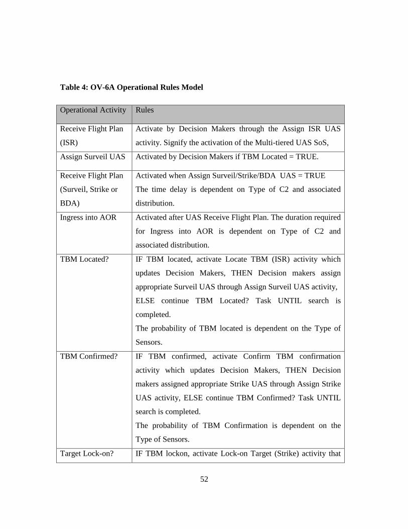
52
Table 4: OV-6A Operational Rules Model
Operational Activity Rules
Receive Flight Plan
(ISR)
Activate by Decision Makers through the Assign ISR UAS
activity. Signify the activation of the Multi-tiered UAS SoS,
Assign Surveil UAS Activated by Decision Makers if TBM Located = TRUE.
Receive Flight Plan
(Surveil, Strike or
BDA)
Activated when Assign Surveil/Strike/BDA UAS = TRUE
The time delay is dependent on Type of C2 and associated
distribution.
Ingress into AOR Activated after UAS Receive Flight Plan. The duration required
for Ingress into AOR is dependent on Type of C2 and
associated distribution.
TBM Located? IF TBM located, activate Locate TBM (ISR) activity which
updates Decision Makers, THEN Decision makers assign
appropriate Surveil UAS through Assign Surveil UAS activity,
ELSE continue TBM Located? Task UNTIL search is
completed.
The probability of TBM located is dependent on the Type of
Sensors.
TBM Confirmed? IF TBM confirmed, activate Confirm TBM confirmation
activity which updates Decision Makers, THEN Decision
makers assigned appropriate Strike UAS through Assign Strike
UAS activity, ELSE continue TBM Confirmed? Task UNTIL
search is completed.
The probability of TBM Confirmation is dependent on the
Type of Sensors.
Target Lock-on? IF TBM lockon, activate Lock-on Target (Strike) activity that
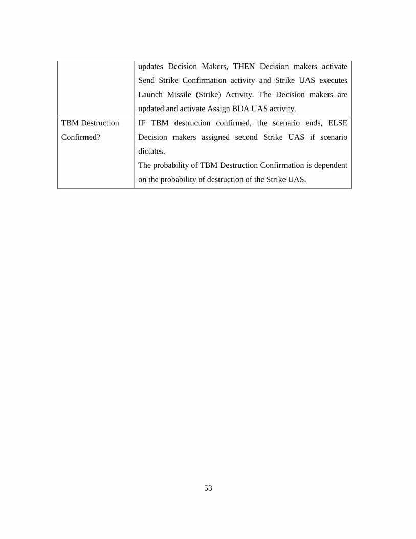
53
updates Decision Makers, THEN Decision makers activate
Send Strike Confirmation activity and Strike UAS executes
Launch Missile (Strike) Activity. The Decision makers are
updated and activate Assign BDA UAS activity.
TBM Destruction
Confirmed?
IF TBM destruction confirmed, the scenario ends, ELSE
Decision makers assigned second Strike UAS if scenario
dictates.
The probability of TBM Destruction Confirmation is dependent
on the probability of destruction of the Strike UAS.
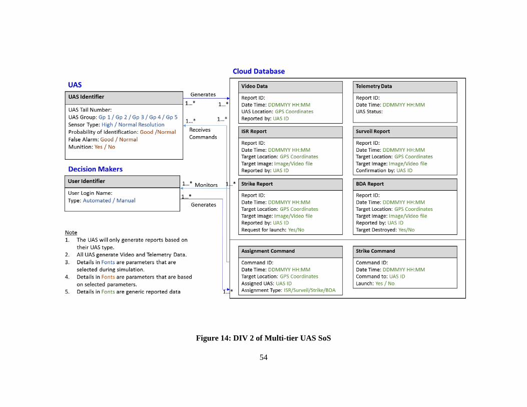
54
Figure 14: DIV 2 of Multi-tier UAS SoS

55
Step 4: Identify Architectural Variants for evaluation
The multi-tiered UAS SoS can be implemented with different capabilities that
will allow the SoS to fulfil the CONOPS and meet the operational needs. However,
different capabilities will result in different development and operational costs, as well as
varying degree of mission effectiveness. For example, a decision-making algorithm can
be developed for the SoS to achieve autonomy or new high-end sensors may be designed
to improve overall effectiveness of the SoS. To effectively evaluate these design variants,
it is necessary to identify the key design parameters and assess the effectiveness based on
the MOEs through simulation using EA.
Due to the time limitation of the research study, the research will focus on the
evaluation of three design parameters in the implementation of the SoS. However, this
methodology is scalable and can be extended to evaluate new design parameters. The
three parameters under considerations are:
a. Decision-making capability:
1. Centralized Manual Command and Control (C2) by ground
commander.
2. Centralized autonomous C2 by pre-identified ISR UAS.
Affects speed of decision making, and quality of decision-making.
56
b. ISR Sensor capability:
1. Normal Sensor with lower Probability of Detection and high False
Alarm rate.
2. High-end sensor with high Probability of Detection and low False
Alarm rate.
Affects Target Acquisition and False Alarm percentages.
c. Number of Strike UAS deployment
1. 1 x Strike UAS deployment
2. 2 x Strike UAS deployment.
Affects Target Destruction percentages.
Step 5: Develop simulation scenario and EA models
To evaluate system, a simulation scenario based on AV-1 and OV-1 is developed,
and the dynamic models are designed based on OV-5, OV-6a and DIV-2. In this
simulation, an Area of Operations (AO) is identified, as marked by the 40 squares in the
diagram shown below. The Simulation is summarized in Figure 15 and the Executable
Architecture is shown in Figure 16, with details from Figure 16a to 16e:

57
Figure 15: Overview of Simulation
The overview of the key processes in the Simulations are as follow:
1. Threat Assessment shows possible TBM deployment within Area of
Operations (AO) [marked by Sq blocks 1 – 40].
2. UAS deploy from staging sites.
3. During each run, 2 targets and 2 false targets are randomly deployed over the
40 grids.
4. 1 x ISR UAS deployed to conduct ISR. Follow anti-clockwise search pattern
over AO.
5. When potential target is located, a Surveil UAS is deployed to Confirm and
track target. The simulation is limited to 2 x Surveil UAS.
6. Strike UAS deploy to strike target, once target confirmed.
7. Small UAS to conduct BDA.
8. Total of 50 runs are carried out per scenario, thus generating a total of 100
targets and 100 false targets.
During each run, the targets are re-deployed randomly over the 40 grids.
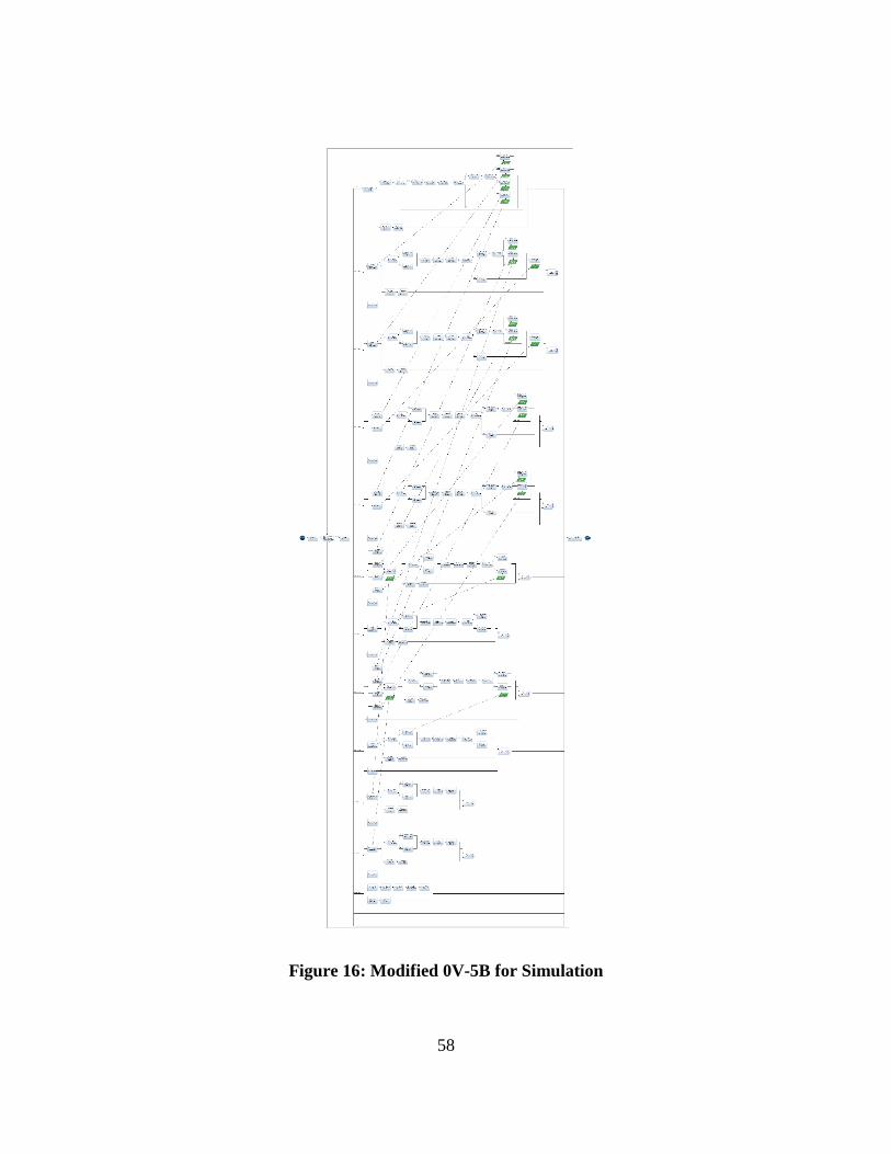
58
Figure 16: Modified 0V-5B for Simulation
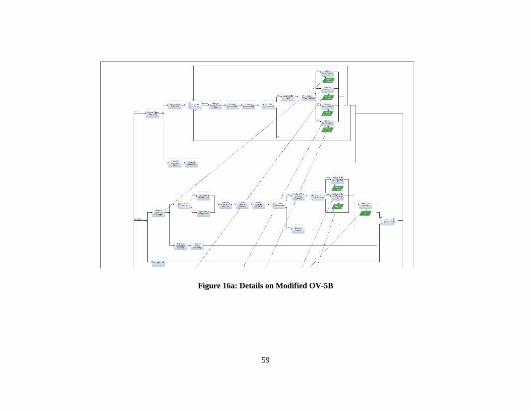
59
Figure 16a: Details on Modified OV-5B
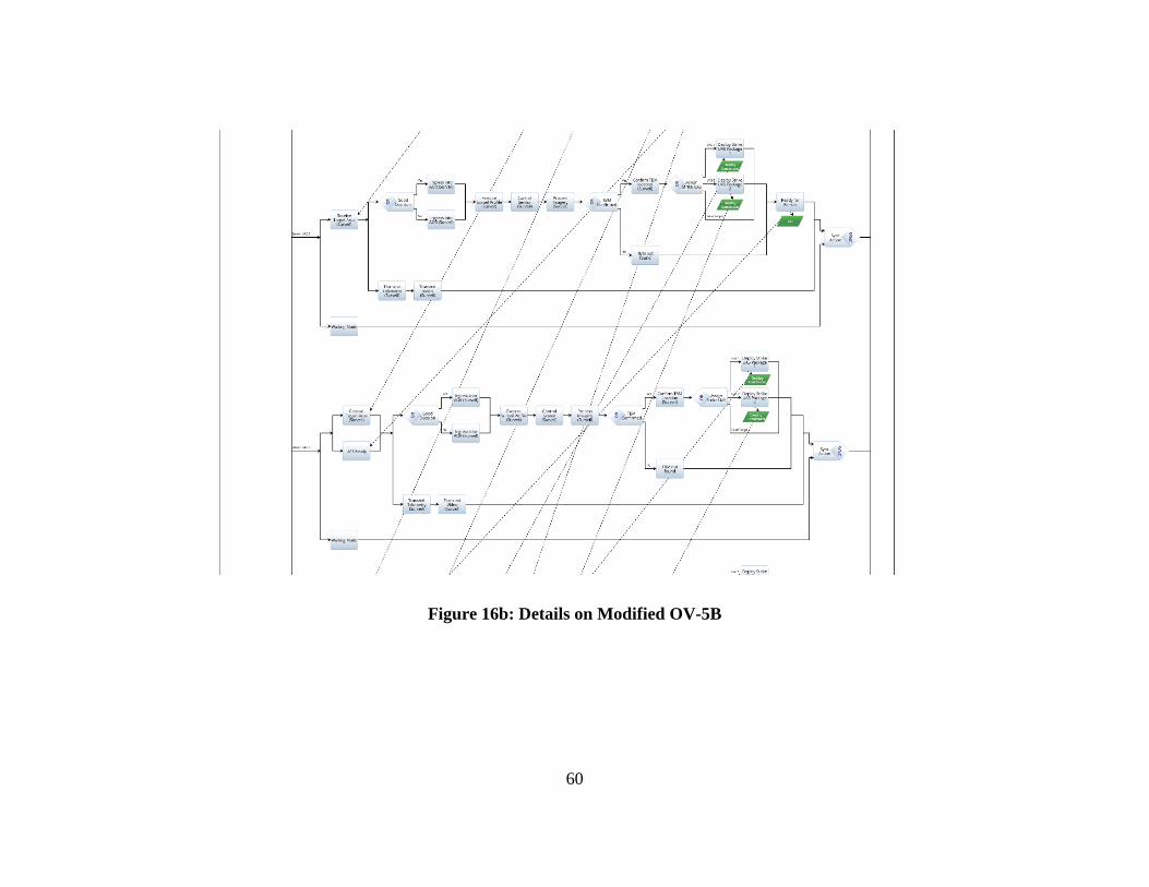
60
Figure 16b: Details on Modified OV-5B
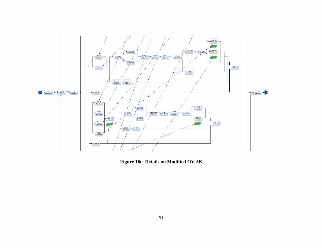
61
Figure 16c: Details on Modified OV-5B
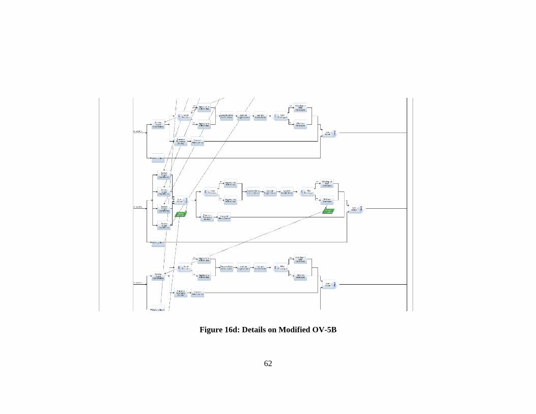
62
Figure 16d: Details on Modified OV-5B
63
Figure 16e: Details on Modified OV-5B
64
To compare between the effectiveness of the different architectural variants, the
following changes are applied to the simulation scenarios as shown in Table 5:
Table 5: 8 Architectural Variants of Multi-tiered UAS SoS for concept evaluation
Centralized Manual C2 Autonomous C2 Operations
Normal ISR Sensor
1 x Strike UAS 1 x Strike UAS 2 x Strike UAS 2 x Strike UAS
High End ISR Sensor
1 x Strike UAS 1 x Strike UAS 2 x Strike UAS 2 x Strike UAS
The scenario will be implemented using Innoslate software. Here, the OV-5b will
form the basis for the development of the EA, and Javascript will be used to incorporate
the decision logic of the systems, and to collect the MOE data, namely:
1. Percentage of Target Confirmed
2. Percentage of False Target
3. Time to Strike
4. Percentage of Target Destroyed
The impact of different variants are incorporated into the different activities nodes
in the OV-5b during simulations:
1. Manual vs Autonomous C2: Affects the speed of decision making and quality
of the decision.
65
a. Speed. The speed of the decision making determines the time delay in
which the respective UAS receive their flight command. As part of the
simulation, it is assumed that the human operator will take longer time to
integrate information before making a decision, while the automated
system will be more efficient in consolidating data and determining the
course of action. Hence, as part of the simulation, the decision making
delay for the human operator process is assumed to twice as long as the
automated system. In addition, it is expected that the automated system
will have a smaller standard deviation as compared to the human operator,
as efficiency of the human operator will vary based on factors such as
experience level and training. This will be implemented in the following
Activities nodes, with the details shown in Table 6:
• Receive Target Area (Surveil) : Time Delay
• Receive Target Coordinates (Strike) : Time Delay
• Receive Strike Area (BDA) : Time Delay
Table 6: Time delay for different Activities Nodes
Receive Target Area (Surveil)
Receive Target Coordinates
(Strike)
Receive Strike Area (BDA)
Manual C2 Normal Distribution: Mean = 15 min Std Dev = 5 min
Normal Distribution: Mean = 12 min Std Dev = 5 min
Normal Distribution: Mean = 12 min Std Dev = 5 min
66
Autonomous C2
Normal Distribution: Mean = 8 min Std Dev = 1 min
Normal Distribution: Mean = 6 min Std Dev = 1 min
Normal Distribution: Mean = 6 min Std Dev = 1 min
b. Quality. The quality of the decision making will be simulated based on
the probability the Ground Commander or the autonomous system selects
the correct UAS in achieving the mission requirement. A good decision
will result in the selection of a better UAS which will have a short time to
reach the target coordinates. For the purpose of this simulation, it is
assumed that the human operator will have a higher probability of
selecting the better solution due to better understanding of the overall
system and operational environment. To provide a quantifiable assessment
of the quality of decision making, a “Good” decision will result in the
selection of a UAS that can ingress and reach the operation areas faster,
while a “Bad” decision will result in selecting the UAS with a longer
ingress time. This is implemented in the following activities nodes, with
details shown in Table 7:
• Ingress into AOR (Surveil) : Duration
• Ingress into AOR (Strike) : Duration
• Ingress into AOR (BDA) : Duration
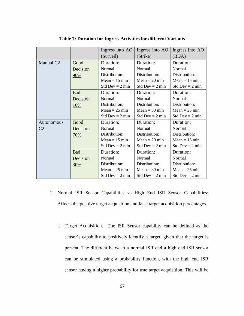
67
Table 7: Duration for Ingress Activities for different Variants
Ingress into AO (Surveil)
Ingress into AO (Strike)
Ingress into AO (BDA)
Manual C2 Good Decision 90%
Duration: Normal Distribution: Mean = 15 min Std Dev = 2 min
Duration: Normal Distribution: Mean = 20 min Std Dev = 2 min
Duration: Normal Distribution: Mean = 15 min Std Dev = 2 min
Bad Decision 10%
Duration: Normal Distribution: Mean = 25 min Std Dev = 2 min
Duration: Normal Distribution: Mean = 30 min Std Dev = 2 min
Duration: Normal Distribution: Mean = 25 min Std Dev = 2 min
Autonomous C2
Good Decision 70%
Duration: Normal Distribution: Mean = 15 min Std Dev = 2 min
Duration: Normal Distribution: Mean = 20 min Std Dev = 2 min
Duration: Normal Distribution: Mean = 15 min Std Dev = 2 min
Bad Decision 30%
Duration: Normal Distribution: Mean = 25 min Std Dev = 2 min
Duration: Normal Distribution: Mean = 30 min Std Dev = 2 min
Duration: Normal Distribution: Mean = 25 min Std Dev = 2 min
2. Normal ISR Sensor Capabilities vs High End ISR Sensor Capabilities:
Affects the positive target acquisition and false target acquisition percentages.
a. Target Acquisition. The ISR Sensor capability can be defined as the
sensor’s capability to positively identify a target, given that the target is
present. The different between a normal ISR and a high end ISR sensor
can be stimulated using a probability function, with the high end ISR
sensor having a higher probability for true target acquisition. This will be
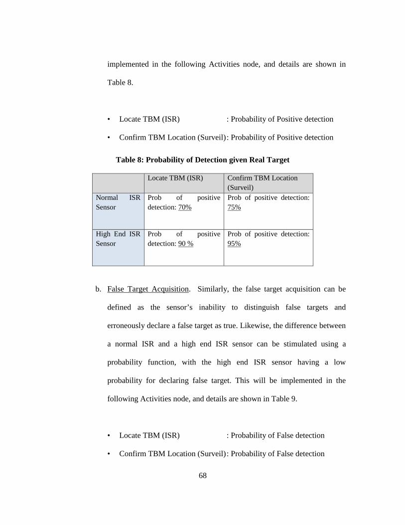
68
implemented in the following Activities node, and details are shown in
Table 8.
• Locate TBM (ISR) : Probability of Positive detection
• Confirm TBM Location (Surveil) : Probability of Positive detection
Table 8: Probability of Detection given Real Target
Locate TBM (ISR) Confirm TBM Location (Surveil)
Normal ISR Sensor
Prob of positive detection: 70%
Prob of positive detection: 75%
High End ISR Sensor
Prob of positive detection: 90 %
Prob of positive detection: 95%
b. False Target Acquisition. Similarly, the false target acquisition can be
defined as the sensor’s inability to distinguish false targets and
erroneously declare a false target as true. Likewise, the difference between
a normal ISR and a high end ISR sensor can be stimulated using a
probability function, with the high end ISR sensor having a low
probability for declaring false target. This will be implemented in the
following Activities node, and details are shown in Table 9.
• Locate TBM (ISR) : Probability of False detection
• Confirm TBM Location (Surveil) : Probability of False detection
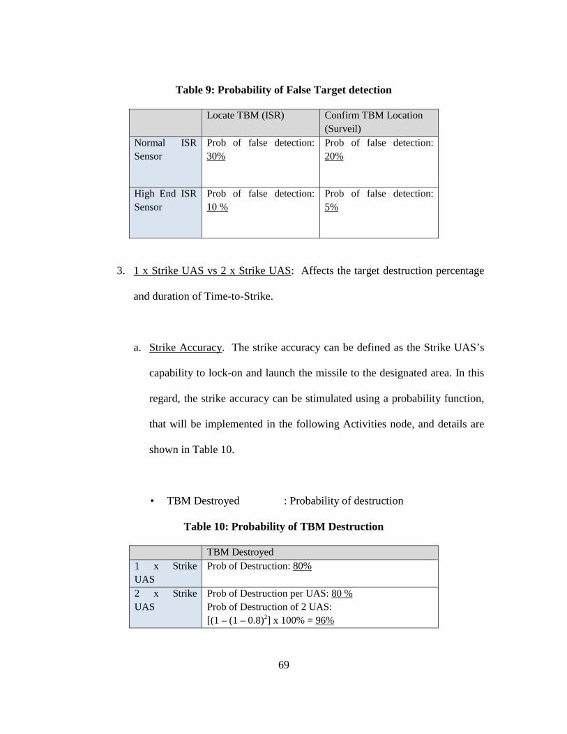
69
Table 9: Probability of False Target detection
Locate TBM (ISR) Confirm TBM Location (Surveil)
Normal ISR Sensor
Prob of false detection: 30%
Prob of false detection: 20%
High End ISR Sensor
Prob of false detection: 10 %
Prob of false detection: 5%
3. 1 x Strike UAS vs 2 x Strike UAS: Affects the target destruction percentage
and duration of Time-to-Strike.
a. Strike Accuracy. The strike accuracy can be defined as the Strike UAS’s
capability to lock-on and launch the missile to the designated area. In this
regard, the strike accuracy can be stimulated using a probability function,
that will be implemented in the following Activities node, and details are
shown in Table 10.
• TBM Destroyed : Probability of destruction
Table 10: Probability of TBM Destruction
TBM Destroyed 1 x Strike UAS
Prob of Destruction: 80%
2 x Strike UAS
Prob of Destruction per UAS: 80 % Prob of Destruction of 2 UAS: [(1 – (1 – 0.8)2] x 100% = 96%

70
Step 6: Data Collection and Analysis
For the data to be statistically significant, Monte Carlo simulation is used. First, as
part of the simulation, each scenario will be simulated with 50 runs across the 40 grids.
Next, the scenario is then simulated 50 times to achieve the Monte Carlo simulations.
Hence, the total number of runs per variants will be 2,500 runs comprising of 50 Monte
Carlo simulation of the scenario and 50 runs within each scenario. The analysis will focus
on the key areas—1) Pairwise comparisons will be carried between the respective
variants to determine the impact of each parameter to the overall system, and 2) OHP
analysis will be conducted to determine the overall performance of each variant across
the different MOEs.
Conclusion
This chapter provides the details in the methodology used in the investigation of
and analysis of the system-under-design through the use of DoDAF models and
simulation using Innoslate software. The results from the simulation are analysed and
presented in Chapter 4.
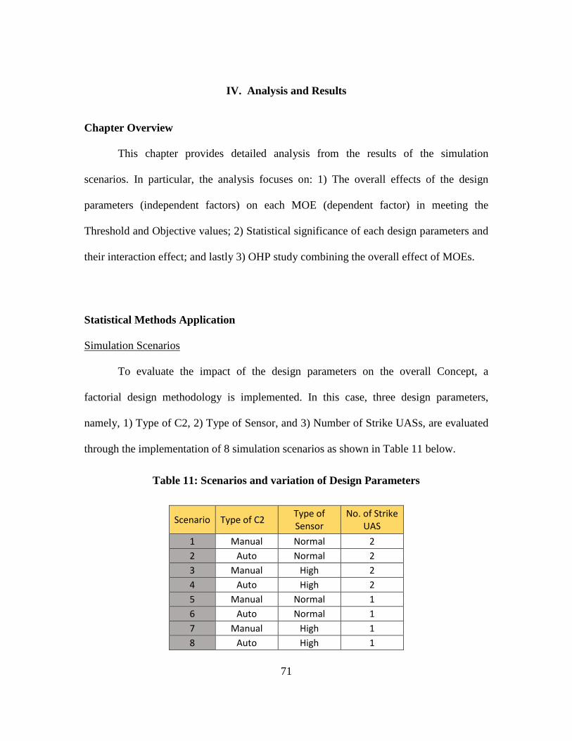
71
IV. Analysis and Results
Chapter Overview
This chapter provides detailed analysis from the results of the simulation
scenarios. In particular, the analysis focuses on: 1) The overall effects of the design
parameters (independent factors) on each MOE (dependent factor) in meeting the
Threshold and Objective values; 2) Statistical significance of each design parameters and
their interaction effect; and lastly 3) OHP study combining the overall effect of MOEs.
Statistical Methods Application
Simulation Scenarios
To evaluate the impact of the design parameters on the overall Concept, a
factorial design methodology is implemented. In this case, three design parameters,
namely, 1) Type of C2, 2) Type of Sensor, and 3) Number of Strike UASs, are evaluated
through the implementation of 8 simulation scenarios as shown in Table 11 below.
Table 11: Scenarios and variation of Design Parameters
Scenario Type of C2 Type of Sensor
No. of Strike UAS
1 Manual Normal 2 2 Auto Normal 2 3 Manual High 2 4 Auto High 2 5 Manual Normal 1 6 Auto Normal 1 7 Manual High 1 8 Auto High 1
72
Statistical Analysis Methodology
The following analytical methodologies are used to assess the results from the
simulations to determine the overall effectiveness of the design parameters on the overall
MOEs, and the individual effect of specific design parameters.
1. Overall Fulfilment of MOEs (Threshold and Objectives): Hypothesis testing
is done to determine if each scenario fulfills the Threshold and the Objective
for the respective MOEs. A one-tail test at 95% confidence interval is used for
each scenario:
Threshold Testing
H0: The mean of the simulation results is equal threshold value (for
Target Acquisition Percentage MOE and Target Destruction
Percentage MOE), or;
The mean of the simulation results is more than threshold value
(for False Alarm Percentage MOE and Time-to-Strike MOE).
HAlternate: The mean of the simulation results is equal threshold value (for
Target Acquisition Percentage MOE and Target Destruction
Percentage MOE), or;
The mean of the simulation results is less than threshold value (for
False Alarm Percentage MOE and Time-to-Strike MOE).
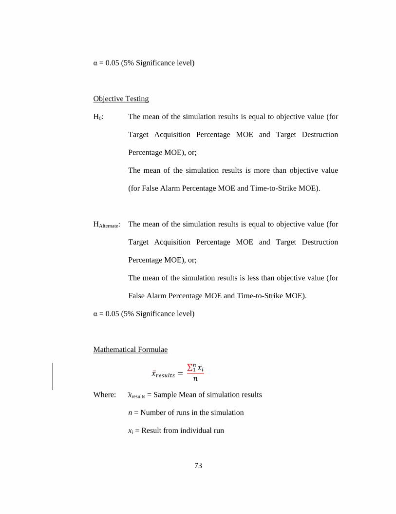
73
α = 0.05 (5% Significance level)
Objective Testing
H0: The mean of the simulation results is equal to objective value (for
Target Acquisition Percentage MOE and Target Destruction
Percentage MOE), or;
The mean of the simulation results is more than objective value
(for False Alarm Percentage MOE and Time-to-Strike MOE).
HAlternate: The mean of the simulation results is equal to objective value (for
Target Acquisition Percentage MOE and Target Destruction
Percentage MOE), or;
The mean of the simulation results is less than objective value (for
False Alarm Percentage MOE and Time-to-Strike MOE).
α = 0.05 (5% Significance level)
Mathematical Formulae
��𝑥𝑟𝑟𝑟𝑟𝑟𝑟𝑟𝑟𝑟𝑟𝑟𝑟𝑟𝑟 = ∑ 𝑥𝑥𝑖𝑖𝑛𝑛1
𝑖𝑖
Where: xresults = Sample Mean of simulation results
n = Number of runs in the simulation
xi = Result from individual run
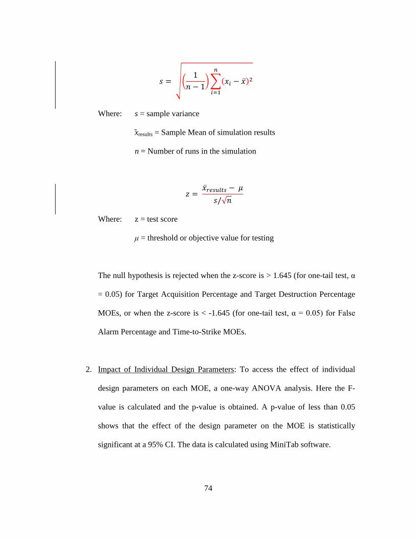
74
𝑖𝑖 = ��1
𝑖𝑖 − 1��(𝑥𝑥𝑖𝑖 − ��𝑥)2
𝑛𝑛
𝑖𝑖=1
Where: s = sample variance
xresults = Sample Mean of simulation results
n = Number of runs in the simulation
𝑧𝑧 = ��𝑥𝑟𝑟𝑟𝑟𝑟𝑟𝑟𝑟𝑟𝑟𝑟𝑟𝑟𝑟 − 𝜇𝜇
𝑖𝑖/√𝑖𝑖
Where: z = test score
μ = threshold or objective value for testing
The null hypothesis is rejected when the z-score is > 1.645 (for one-tail test, α
= 0.05) for Target Acquisition Percentage and Target Destruction Percentage
MOEs, or when the z-score is < -1.645 (for one-tail test, α = 0.05) for False
Alarm Percentage and Time-to-Strike MOEs.
2. Impact of Individual Design Parameters: To access the effect of individual
design parameters on each MOE, a one-way ANOVA analysis. Here the F-
value is calculated and the p-value is obtained. A p-value of less than 0.05
shows that the effect of the design parameter on the MOE is statistically
significant at a 95% CI. The data is calculated using MiniTab software.
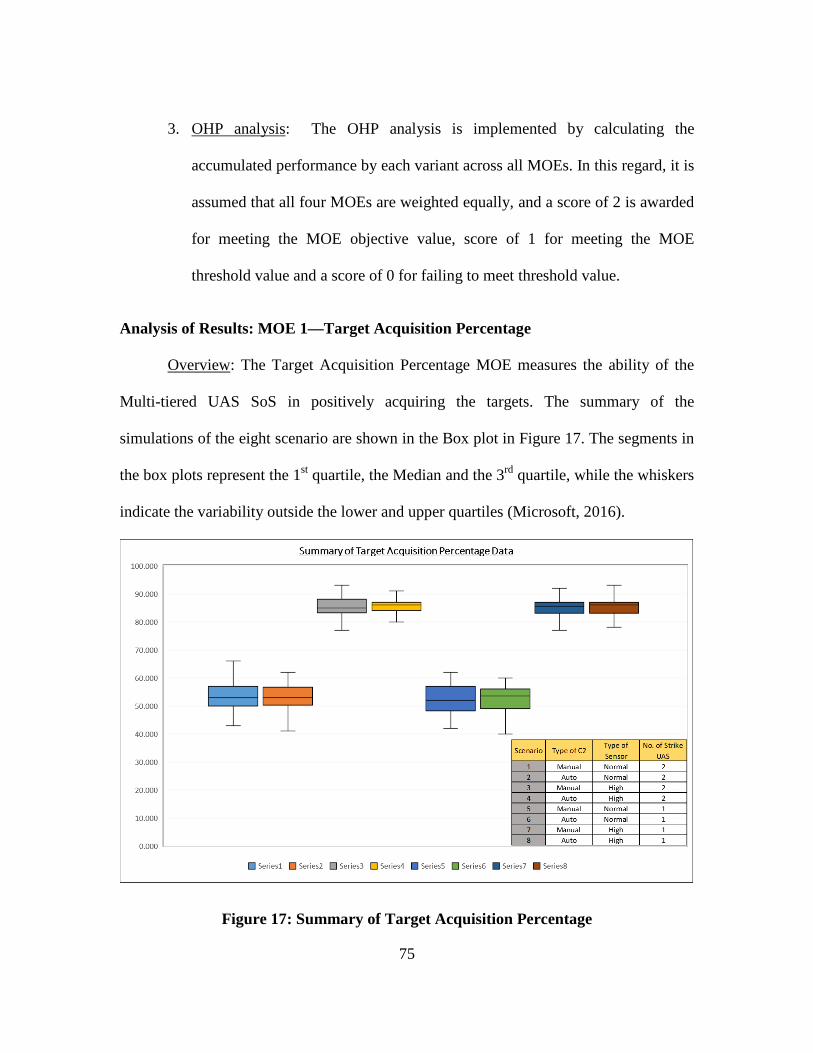
75
3. OHP analysis: The OHP analysis is implemented by calculating the
accumulated performance by each variant across all MOEs. In this regard, it is
assumed that all four MOEs are weighted equally, and a score of 2 is awarded
for meeting the MOE objective value, score of 1 for meeting the MOE
threshold value and a score of 0 for failing to meet threshold value.
Analysis of Results: MOE 1—Target Acquisition Percentage
Overview: The Target Acquisition Percentage MOE measures the ability of the
Multi-tiered UAS SoS in positively acquiring the targets. The summary of the
simulations of the eight scenario are shown in the Box plot in Figure 17. The segments in
the box plots represent the 1st quartile, the Median and the 3rd quartile, while the whiskers
indicate the variability outside the lower and upper quartiles (Microsoft, 2016).
Figure 17: Summary of Target Acquisition Percentage
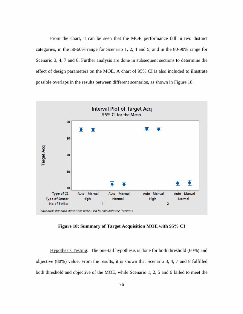
76
From the chart, it can be seen that the MOE performance fall in two distinct
categories, in the 50-60% range for Scenario 1, 2, 4 and 5, and in the 80-90% range for
Scenario 3, 4, 7 and 8. Further analysis are done in subsequent sections to determine the
effect of design parameters on the MOE. A chart of 95% CI is also included to illustrate
possible overlaps in the results between different scenarios, as shown in Figure 18.
Figure 18: Summary of Target Acquisition MOE with 95% CI
Hypothesis Testing: The one-tail hypothesis is done for both threshold (60%) and
objective (80%) value. From the results, it is shown that Scenario 3, 4, 7 and 8 fulfilled
both threshold and objective of the MOE, while Scenario 1, 2, 5 and 6 failed to meet the
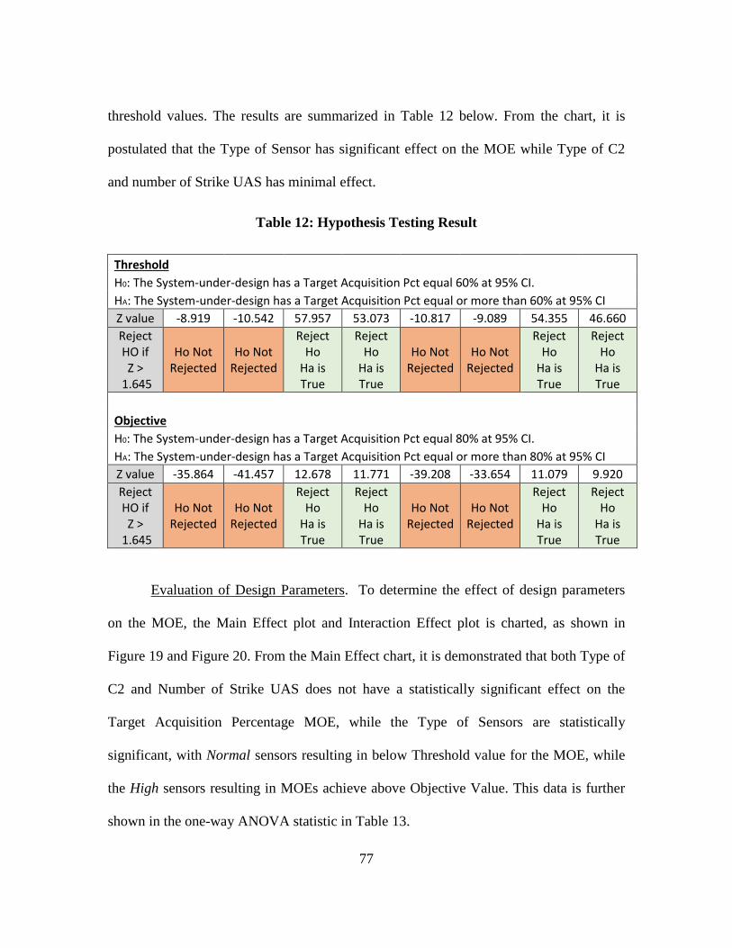
77
threshold values. The results are summarized in Table 12 below. From the chart, it is
postulated that the Type of Sensor has significant effect on the MOE while Type of C2
and number of Strike UAS has minimal effect.
Table 12: Hypothesis Testing Result
Threshold H0: The System-under-design has a Target Acquisition Pct equal 60% at 95% CI.
HA: The System-under-design has a Target Acquisition Pct equal or more than 60% at 95% CI Z value -8.919 -10.542 57.957 53.073 -10.817 -9.089 54.355 46.660 Reject HO if Z >
1.645
Ho Not Rejected
Ho Not Rejected
Reject Ho
Ha is True
Reject Ho
Ha is True
Ho Not Rejected
Ho Not Rejected
Reject Ho
Ha is True
Reject Ho
Ha is True
Objective H0: The System-under-design has a Target Acquisition Pct equal 80% at 95% CI.
HA: The System-under-design has a Target Acquisition Pct equal or more than 80% at 95% CI Z value -35.864 -41.457 12.678 11.771 -39.208 -33.654 11.079 9.920 Reject HO if Z >
1.645
Ho Not Rejected
Ho Not Rejected
Reject Ho
Ha is True
Reject Ho
Ha is True
Ho Not Rejected
Ho Not Rejected
Reject Ho
Ha is True
Reject Ho
Ha is True
Evaluation of Design Parameters. To determine the effect of design parameters
on the MOE, the Main Effect plot and Interaction Effect plot is charted, as shown in
Figure 19 and Figure 20. From the Main Effect chart, it is demonstrated that both Type of
C2 and Number of Strike UAS does not have a statistically significant effect on the
Target Acquisition Percentage MOE, while the Type of Sensors are statistically
significant, with Normal sensors resulting in below Threshold value for the MOE, while
the High sensors resulting in MOEs achieve above Objective Value. This data is further
shown in the one-way ANOVA statistic in Table 13.
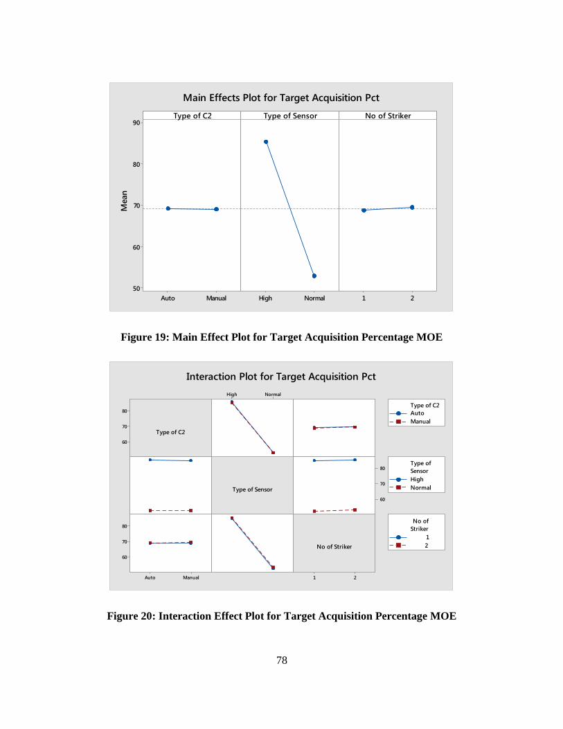
78
Figure 19: Main Effect Plot for Target Acquisition Percentage MOE
Figure 20: Interaction Effect Plot for Target Acquisition Percentage MOE
ManualAuto
90
80
70
60
50NormalHigh 21
Type of C2M
ean
Type of Sensor No of Striker
Main Effects Plot for Target Acquisition Pct
80
70
60
21
NormalHigh
80
70
60
ManualAuto
80
70
60
Type of C2
Type of Sensor
No of Striker
AutoManual
Type of C2
HighNormal
SensorType of
12
StrikerNo of
Interaction Plot for Target Acquisition Pct
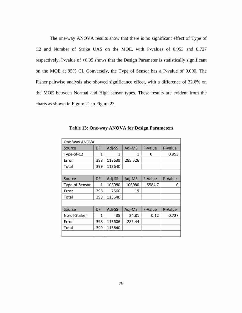
79
The one-way ANOVA results show that there is no significant effect of Type of
C2 and Number of Strike UAS on the MOE, with P-values of 0.953 and 0.727
respectively. P-value of <0.05 shows that the Design Parameter is statistically significant
on the MOE at 95% CI. Conversely, the Type of Sensor has a P-value of 0.000. The
Fisher pairwise analysis also showed significance effect, with a difference of 32.6% on
the MOE between Normal and High sensor types. These results are evident from the
charts as shown in Figure 21 to Figure 23.
Table 13: One-way ANOVA for Design Parameters
One Way ANOVA Source DF Adj-SS Adj-MS F-Value P-Value Type-of-C2 1 1 1 0 0.953 Error 398 113639 285.526 Total 399 113640
Source DF Adj-SS Adj-MS F-Value P-Value Type-of-Sensor 1 106080 106080 5584.7 0 Error 398 7560 19 Total 399 113640
Source DF Adj-SS Adj-MS F-Value P-Value No-of-Striker 1 35 34.81 0.12 0.727 Error 398 113606 285.44 Total 399 113640
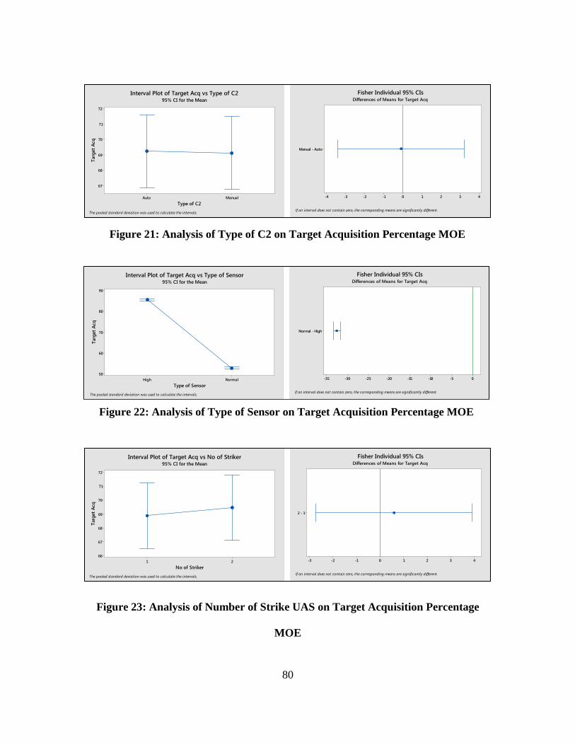
80
Figure 23: Analysis of Number of Strike UAS on Target Acquisition Percentage
MOE
ManualAuto
72
71
70
69
68
67
Type of C2
Targ
et A
cqInterval Plot of Target Acq vs Type of C2
95% CI for the Mean
The pooled standard deviation was used to calculate the intervals.
Manual - Auto
43210-1-2-3-4
If an interval does not contain zero, the corresponding means are significantly different.
Fisher Individual 95% CIsDifferences of Means for Target Acq
NormalHigh
90
80
70
60
50
Type of Sensor
Targ
et A
cq
Interval Plot of Target Acq vs Type of Sensor95% CI for the Mean
The pooled standard deviation was used to calculate the intervals.
Normal - High
0-5-10-15-20-25-30-35
If an interval does not contain zero, the corresponding means are significantly different.
Fisher Individual 95% CIsDifferences of Means for Target Acq
21
72
71
70
69
68
67
66
No of Striker
Targ
et A
cq
Interval Plot of Target Acq vs No of Striker95% CI for the Mean
The pooled standard deviation was used to calculate the intervals.
2 - 1
43210-1-2-3
If an interval does not contain zero, the corresponding means are significantly different.
Fisher Individual 95% CIsDifferences of Means for Target Acq
Figure 21: Analysis of Type of C2 on Target Acquisition Percentage MOE
Figure 22: Analysis of Type of Sensor on Target Acquisition Percentage MOE
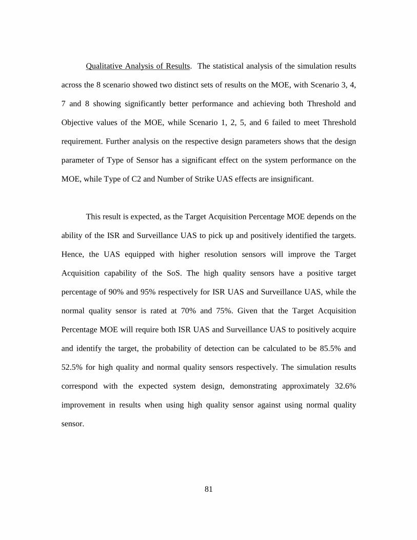
81
Qualitative Analysis of Results. The statistical analysis of the simulation results
across the 8 scenario showed two distinct sets of results on the MOE, with Scenario 3, 4,
7 and 8 showing significantly better performance and achieving both Threshold and
Objective values of the MOE, while Scenario 1, 2, 5, and 6 failed to meet Threshold
requirement. Further analysis on the respective design parameters shows that the design
parameter of Type of Sensor has a significant effect on the system performance on the
MOE, while Type of C2 and Number of Strike UAS effects are insignificant.
This result is expected, as the Target Acquisition Percentage MOE depends on the
ability of the ISR and Surveillance UAS to pick up and positively identified the targets.
Hence, the UAS equipped with higher resolution sensors will improve the Target
Acquisition capability of the SoS. The high quality sensors have a positive target
percentage of 90% and 95% respectively for ISR UAS and Surveillance UAS, while the
normal quality sensor is rated at 70% and 75%. Given that the Target Acquisition
Percentage MOE will require both ISR UAS and Surveillance UAS to positively acquire
and identify the target, the probability of detection can be calculated to be 85.5% and
52.5% for high quality and normal quality sensors respectively. The simulation results
correspond with the expected system design, demonstrating approximately 32.6%
improvement in results when using high quality sensor against using normal quality
sensor.
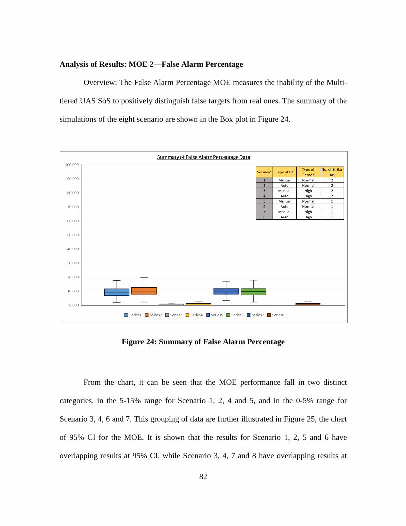
82
Analysis of Results: MOE 2—False Alarm Percentage
Overview: The False Alarm Percentage MOE measures the inability of the Multi-
tiered UAS SoS to positively distinguish false targets from real ones. The summary of the
simulations of the eight scenario are shown in the Box plot in Figure 24.
Figure 24: Summary of False Alarm Percentage
From the chart, it can be seen that the MOE performance fall in two distinct
categories, in the 5-15% range for Scenario 1, 2, 4 and 5, and in the 0-5% range for
Scenario 3, 4, 6 and 7. This grouping of data are further illustrated in Figure 25, the chart
of 95% CI for the MOE. It is shown that the results for Scenario 1, 2, 5 and 6 have
overlapping results at 95% CI, while Scenario 3, 4, 7 and 8 have overlapping results at
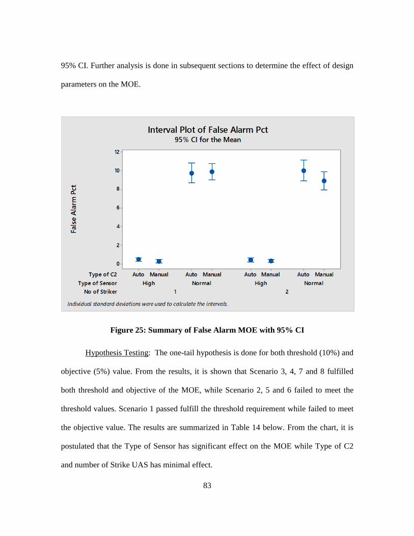
83
95% CI. Further analysis is done in subsequent sections to determine the effect of design
parameters on the MOE.
Figure 25: Summary of False Alarm MOE with 95% CI
Hypothesis Testing: The one-tail hypothesis is done for both threshold (10%) and
objective (5%) value. From the results, it is shown that Scenario 3, 4, 7 and 8 fulfilled
both threshold and objective of the MOE, while Scenario 2, 5 and 6 failed to meet the
threshold values. Scenario 1 passed fulfill the threshold requirement while failed to meet
the objective value. The results are summarized in Table 14 below. From the chart, it is
postulated that the Type of Sensor has significant effect on the MOE while Type of C2
and number of Strike UAS has minimal effect.
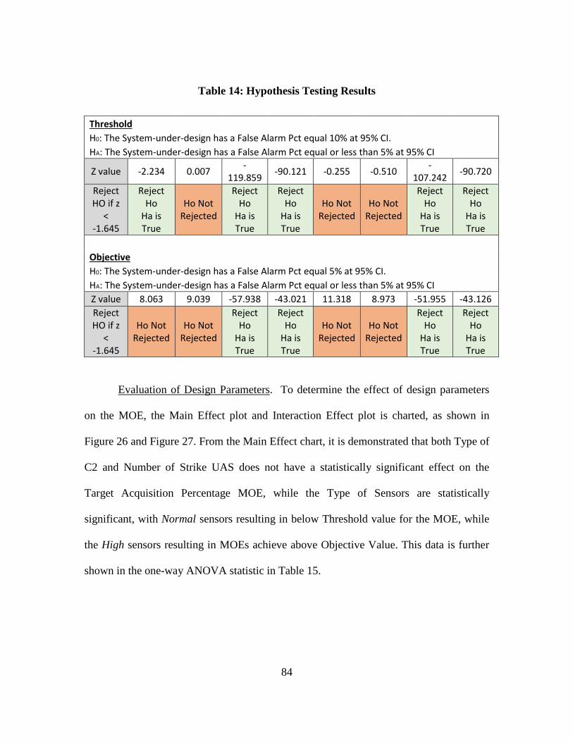
84
Table 14: Hypothesis Testing Results
Threshold H0: The System-under-design has a False Alarm Pct equal 10% at 95% CI.
HA: The System-under-design has a False Alarm Pct equal or less than 5% at 95% CI
Z value -2.234 0.007 -119.859 -90.121 -0.255 -0.510 -
107.242 -90.720
Reject HO if z
< -1.645
Reject Ho
Ha is True
Ho Not Rejected
Reject Ho
Ha is True
Reject Ho
Ha is True
Ho Not Rejected
Ho Not Rejected
Reject Ho
Ha is True
Reject Ho
Ha is True
Objective H0: The System-under-design has a False Alarm Pct equal 5% at 95% CI.
HA: The System-under-design has a False Alarm Pct equal or less than 5% at 95% CI Z value 8.063 9.039 -57.938 -43.021 11.318 8.973 -51.955 -43.126
Reject HO if z
< -1.645
Ho Not Rejected
Ho Not Rejected
Reject Ho
Ha is True
Reject Ho
Ha is True
Ho Not Rejected
Ho Not Rejected
Reject Ho
Ha is True
Reject Ho
Ha is True
Evaluation of Design Parameters. To determine the effect of design parameters
on the MOE, the Main Effect plot and Interaction Effect plot is charted, as shown in
Figure 26 and Figure 27. From the Main Effect chart, it is demonstrated that both Type of
C2 and Number of Strike UAS does not have a statistically significant effect on the
Target Acquisition Percentage MOE, while the Type of Sensors are statistically
significant, with Normal sensors resulting in below Threshold value for the MOE, while
the High sensors resulting in MOEs achieve above Objective Value. This data is further
shown in the one-way ANOVA statistic in Table 15.
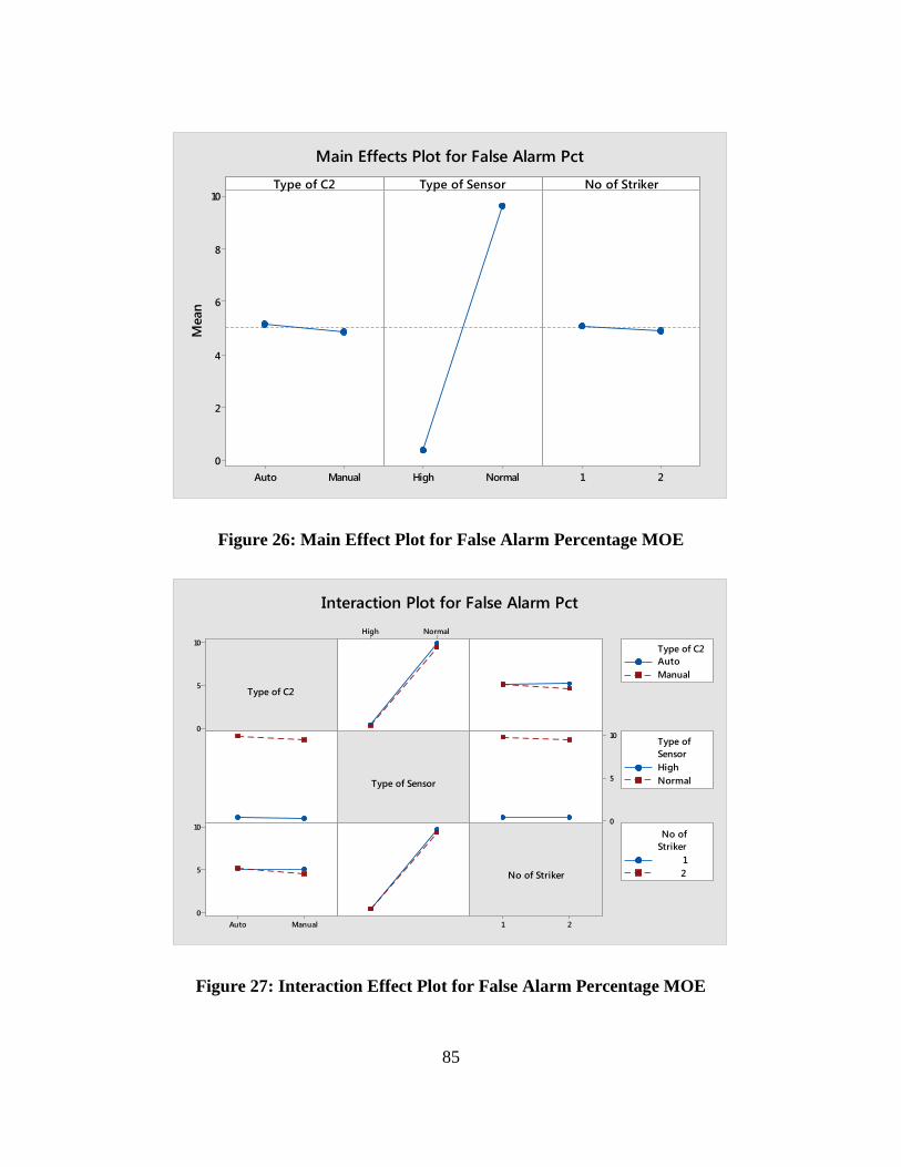
85
Figure 26: Main Effect Plot for False Alarm Percentage MOE
Figure 27: Interaction Effect Plot for False Alarm Percentage MOE
ManualAuto
10
8
6
4
2
0NormalHigh 21
Type of C2M
ean
Type of Sensor No of Striker
Main Effects Plot for False Alarm Pct
10
5
0
21
NormalHigh
10
5
0
ManualAuto
10
5
0
Type of C2
Type of Sensor
No of Striker
AutoManual
Type of C2
HighNormal
SensorType of
12
StrikerNo of
Interaction Plot for False Alarm Pct
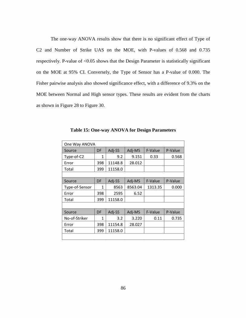
86
The one-way ANOVA results show that there is no significant effect of Type of
C2 and Number of Strike UAS on the MOE, with P-values of 0.568 and 0.735
respectively. P-value of <0.05 shows that the Design Parameter is statistically significant
on the MOE at 95% CI. Conversely, the Type of Sensor has a P-value of 0.000. The
Fisher pairwise analysis also showed significance effect, with a difference of 9.3% on the
MOE between Normal and High sensor types. These results are evident from the charts
as shown in Figure 28 to Figure 30.
Table 15: One-way ANOVA for Design Parameters
One Way ANOVA Source DF Adj-SS Adj-MS F-Value P-Value Type-of-C2 1 9.2 9.151 0.33 0.568 Error 398 11148.8 28.012 Total 399 11158.0
Source DF Adj-SS Adj-MS F-Value P-Value Type-of-Sensor 1 8563 8563.04 1313.35 0.000 Error 398 2595 6.52 Total 399 11158.0
Source DF Adj-SS Adj-MS F-Value P-Value No-of-Striker 1 3.2 3.220 0.11 0.735 Error 398 11154.8 28.027 Total 399 11158.0
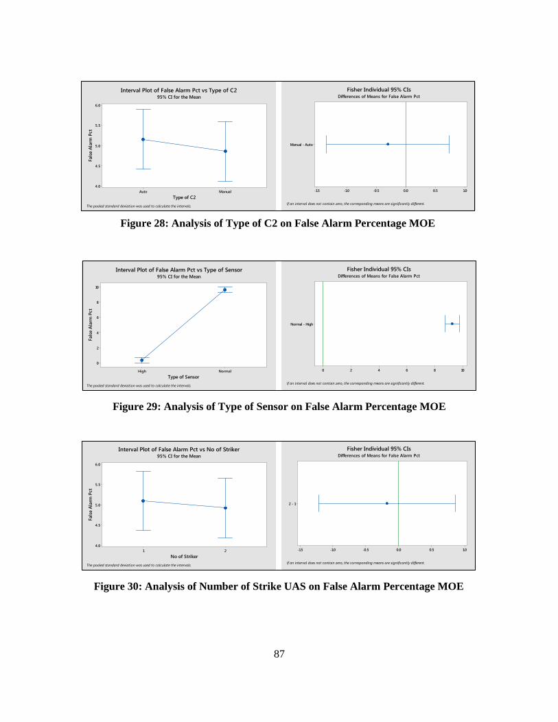
87
Qualitative Analysis of Result. The statistical analysis of the simulation results
ManualAuto
6.0
5.5
5.0
4.5
4.0
Type of C2
Fals
e Al
arm
Pct
Interval Plot of False Alarm Pct vs Type of C295% CI for the Mean
The pooled standard deviation was used to calculate the intervals.
Manual - Auto
1.00.50.0-0.5-1.0-1.5
If an interval does not contain zero, the corresponding means are significantly different.
Fisher Individual 95% CIsDifferences of Means for False Alarm Pct
NormalHigh
10
8
6
4
2
0
Type of Sensor
Fals
e Al
arm
Pct
Interval Plot of False Alarm Pct vs Type of Sensor95% CI for the Mean
The pooled standard deviation was used to calculate the intervals.
Normal - High
1086420
If an interval does not contain zero, the corresponding means are significantly different.
Fisher Individual 95% CIsDifferences of Means for False Alarm Pct
21
6.0
5.5
5.0
4.5
4.0
No of Striker
Fals
e Al
arm
Pct
Interval Plot of False Alarm Pct vs No of Striker95% CI for the Mean
The pooled standard deviation was used to calculate the intervals.
2 - 1
1.00.50.0-0.5-1.0-1.5
If an interval does not contain zero, the corresponding means are significantly different.
Fisher Individual 95% CIsDifferences of Means for False Alarm Pct
Figure 30: Analysis of Number of Strike UAS on False Alarm Percentage MOE
Figure 28: Analysis of Type of C2 on False Alarm Percentage MOE
Figure 29: Analysis of Type of Sensor on False Alarm Percentage MOE
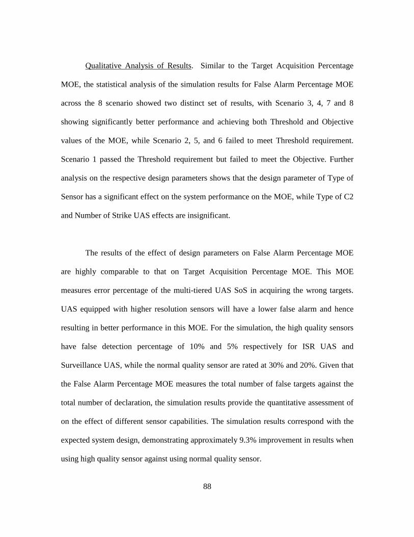
88
Qualitative Analysis of Results. Similar to the Target Acquisition Percentage
MOE, the statistical analysis of the simulation results for False Alarm Percentage MOE
across the 8 scenario showed two distinct set of results, with Scenario 3, 4, 7 and 8
showing significantly better performance and achieving both Threshold and Objective
values of the MOE, while Scenario 2, 5, and 6 failed to meet Threshold requirement.
Scenario 1 passed the Threshold requirement but failed to meet the Objective. Further
analysis on the respective design parameters shows that the design parameter of Type of
Sensor has a significant effect on the system performance on the MOE, while Type of C2
and Number of Strike UAS effects are insignificant.
The results of the effect of design parameters on False Alarm Percentage MOE
are highly comparable to that on Target Acquisition Percentage MOE. This MOE
measures error percentage of the multi-tiered UAS SoS in acquiring the wrong targets.
UAS equipped with higher resolution sensors will have a lower false alarm and hence
resulting in better performance in this MOE. For the simulation, the high quality sensors
have false detection percentage of 10% and 5% respectively for ISR UAS and
Surveillance UAS, while the normal quality sensor are rated at 30% and 20%. Given that
the False Alarm Percentage MOE measures the total number of false targets against the
total number of declaration, the simulation results provide the quantitative assessment of
on the effect of different sensor capabilities. The simulation results correspond with the
expected system design, demonstrating approximately 9.3% improvement in results when
using high quality sensor against using normal quality sensor.
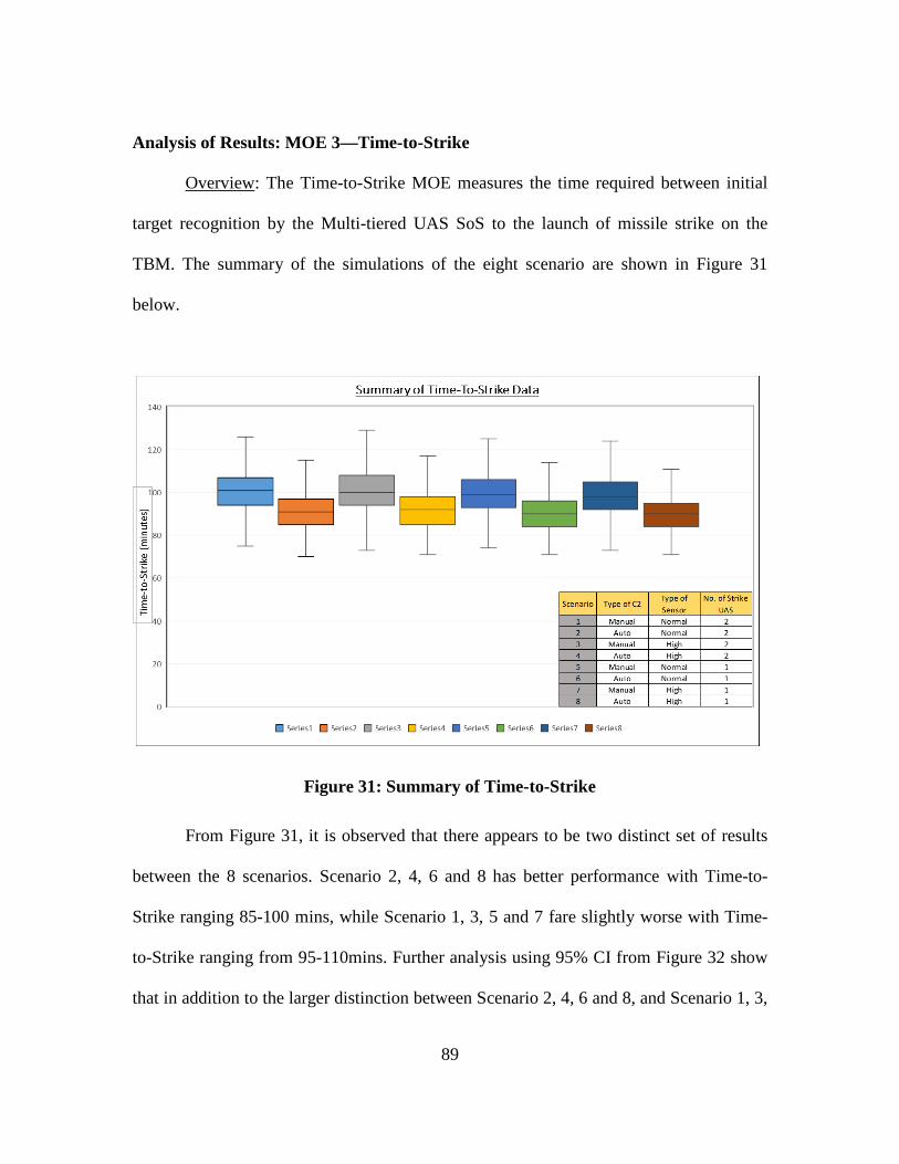
89
Analysis of Results: MOE 3—Time-to-Strike
Overview: The Time-to-Strike MOE measures the time required between initial
target recognition by the Multi-tiered UAS SoS to the launch of missile strike on the
TBM. The summary of the simulations of the eight scenario are shown in Figure 31
below.
Figure 31: Summary of Time-to-Strike
From Figure 31, it is observed that there appears to be two distinct set of results
between the 8 scenarios. Scenario 2, 4, 6 and 8 has better performance with Time-to-
Strike ranging 85-100 mins, while Scenario 1, 3, 5 and 7 fare slightly worse with Time-
to-Strike ranging from 95-110mins. Further analysis using 95% CI from Figure 32 show
that in addition to the larger distinction between Scenario 2, 4, 6 and 8, and Scenario 1, 3,
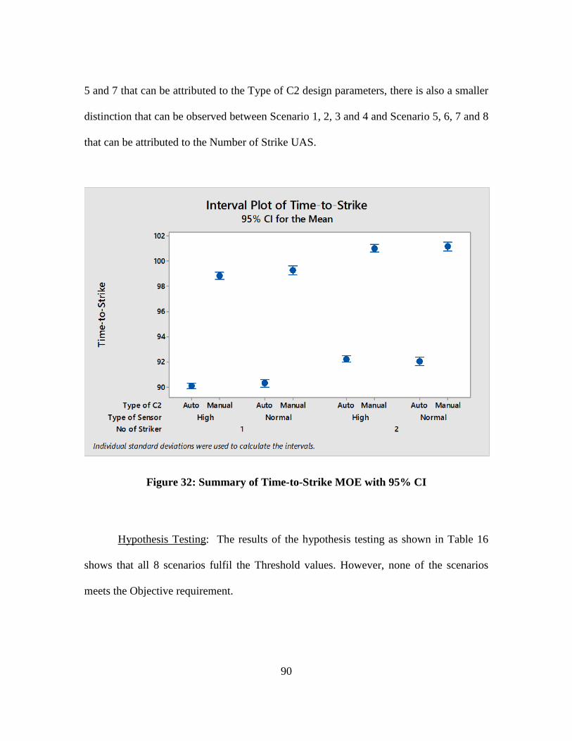
90
5 and 7 that can be attributed to the Type of C2 design parameters, there is also a smaller
distinction that can be observed between Scenario 1, 2, 3 and 4 and Scenario 5, 6, 7 and 8
that can be attributed to the Number of Strike UAS.
Figure 32: Summary of Time-to-Strike MOE with 95% CI
Hypothesis Testing: The results of the hypothesis testing as shown in Table 16
shows that all 8 scenarios fulfil the Threshold values. However, none of the scenarios
meets the Objective requirement.
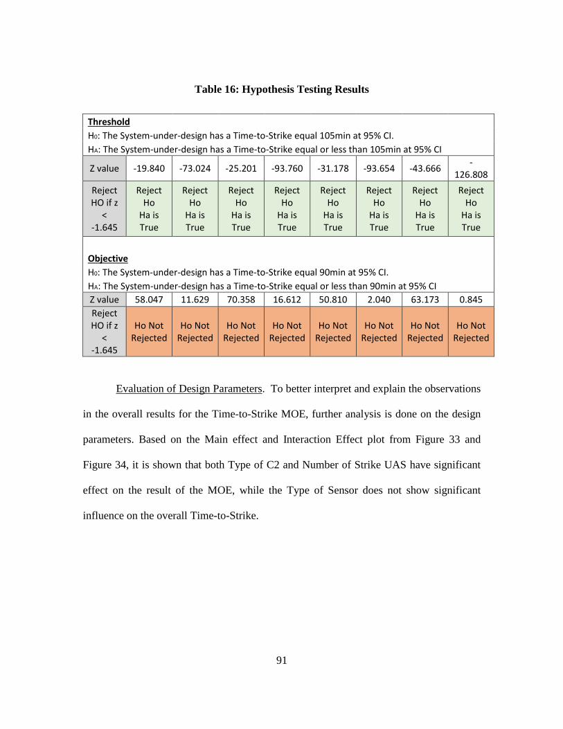
91
Table 16: Hypothesis Testing Results
Threshold H0: The System-under-design has a Time-to-Strike equal 105min at 95% CI.
HA: The System-under-design has a Time-to-Strike equal or less than 105min at 95% CI
Z value -19.840 -73.024 -25.201 -93.760 -31.178 -93.654 -43.666 -126.808
Reject HO if z
< -1.645
Reject Ho
Ha is True
Reject Ho
Ha is True
Reject Ho
Ha is True
Reject Ho
Ha is True
Reject Ho
Ha is True
Reject Ho
Ha is True
Reject Ho
Ha is True
Reject Ho
Ha is True
Objective H0: The System-under-design has a Time-to-Strike equal 90min at 95% CI.
HA: The System-under-design has a Time-to-Strike equal or less than 90min at 95% CI Z value 58.047 11.629 70.358 16.612 50.810 2.040 63.173 0.845 Reject HO if z
< -1.645
Ho Not Rejected
Ho Not Rejected
Ho Not Rejected
Ho Not Rejected
Ho Not Rejected
Ho Not Rejected
Ho Not Rejected
Ho Not Rejected
Evaluation of Design Parameters. To better interpret and explain the observations
in the overall results for the Time-to-Strike MOE, further analysis is done on the design
parameters. Based on the Main effect and Interaction Effect plot from Figure 33 and
Figure 34, it is shown that both Type of C2 and Number of Strike UAS have significant
effect on the result of the MOE, while the Type of Sensor does not show significant
influence on the overall Time-to-Strike.
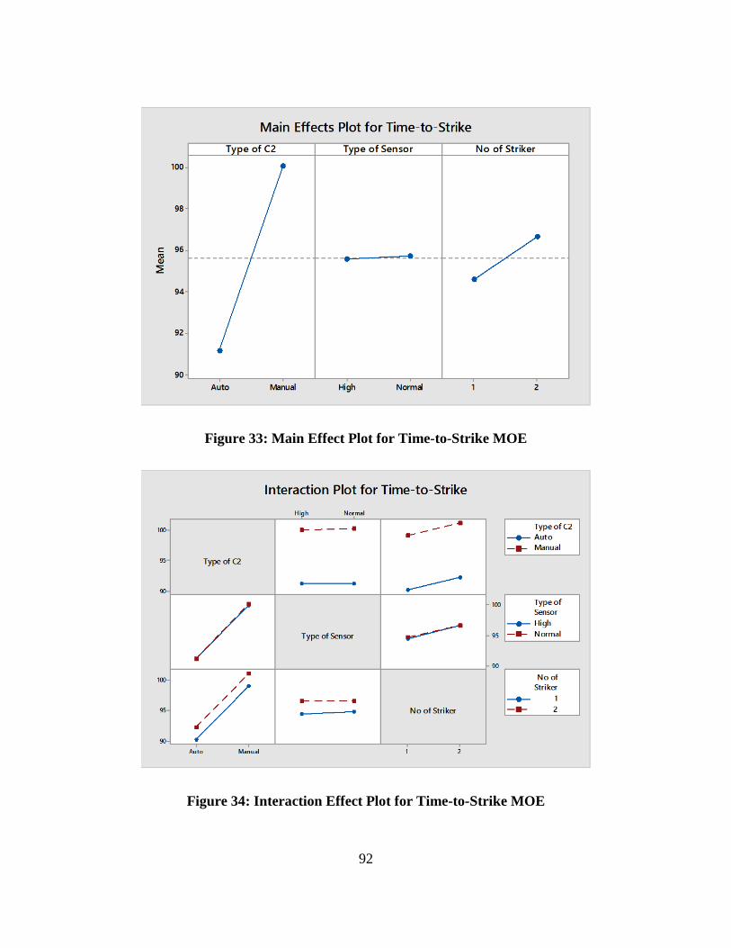
92
Figure 33: Main Effect Plot for Time-to-Strike MOE
Figure 34: Interaction Effect Plot for Time-to-Strike MOE
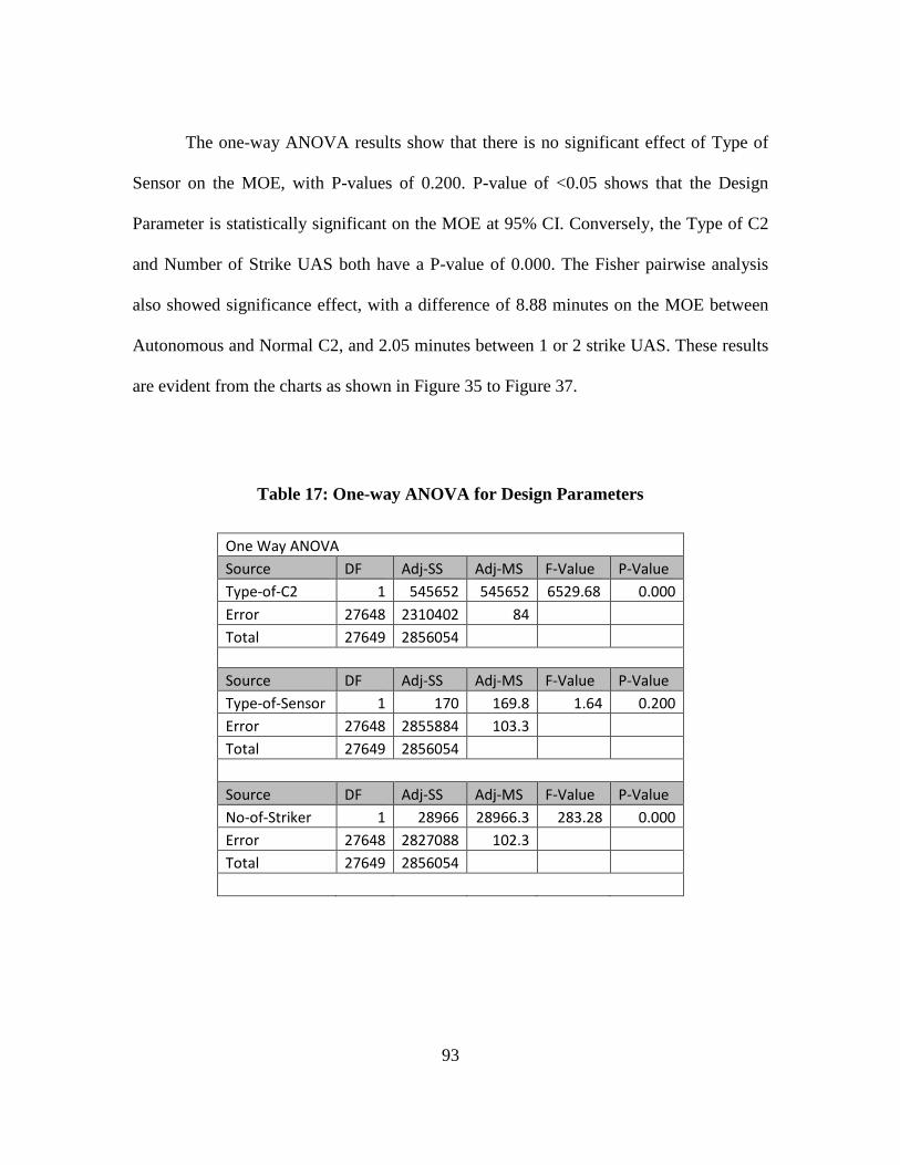
93
The one-way ANOVA results show that there is no significant effect of Type of
Sensor on the MOE, with P-values of 0.200. P-value of <0.05 shows that the Design
Parameter is statistically significant on the MOE at 95% CI. Conversely, the Type of C2
and Number of Strike UAS both have a P-value of 0.000. The Fisher pairwise analysis
also showed significance effect, with a difference of 8.88 minutes on the MOE between
Autonomous and Normal C2, and 2.05 minutes between 1 or 2 strike UAS. These results
are evident from the charts as shown in Figure 35 to Figure 37.
Table 17: One-way ANOVA for Design Parameters
One Way ANOVA Source DF Adj-SS Adj-MS F-Value P-Value Type-of-C2 1 545652 545652 6529.68 0.000 Error 27648 2310402 84 Total 27649 2856054
Source DF Adj-SS Adj-MS F-Value P-Value Type-of-Sensor 1 170 169.8 1.64 0.200 Error 27648 2855884 103.3 Total 27649 2856054
Source DF Adj-SS Adj-MS F-Value P-Value No-of-Striker 1 28966 28966.3 283.28 0.000 Error 27648 2827088 102.3 Total 27649 2856054
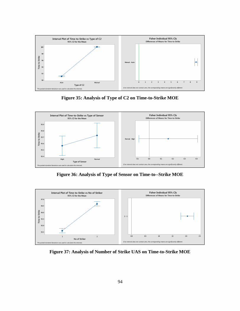
94
ManualAuto
100
98
96
94
92
90
Type of C2
Tim
e-to
-Str
ike
Interval Plot of Time-to-Strike vs Type of C295% CI for the Mean
The pooled standard deviation was used to calculate the intervals.
Manual - Auto
9876543210
If an interval does not contain zero, the corresponding means are significantly different.
Fisher Individual 95% CIsDifferences of Means for Time-to-Strike
NormalHigh
95.9
95.8
95.7
95.6
95.5
95.4
Type of Sensor
Tim
e-to
-Str
ike
Interval Plot of Time-to-Strike vs Type of Sensor95% CI for the Mean
The pooled standard deviation was used to calculate the intervals.
Normal - High
0.40.30.20.10.0-0.1
If an interval does not contain zero, the corresponding means are significantly different.
Fisher Individual 95% CIsDifferences of Means for Time-to-Strike
21
97.0
96.5
96.0
95.5
95.0
94.5
No of Striker
Tim
e-to
-Str
ike
Interval Plot of Time-to-Strike vs No of Striker95% CI for the Mean
The pooled standard deviation was used to calculate the intervals.
2 - 1
2.52.01.51.00.50.0
If an interval does not contain zero, the corresponding means are significantly different.
Fisher Individual 95% CIsDifferences of Means for Time-to-Strike
Figure 35: Analysis of Type of C2 on Time-to-Strike MOE
Figure 36: Analysis of Type of Sensor on Time-to--Strike MOE
Figure 37: Analysis of Number of Strike UAS on Time-to-Strike MOE
95
Qualitative Analysis of Results. While initial assessment of the simulation results
for Time-to-Strike MOE shows two set of results for Scenarios 1, 3, 5 and 7 and
Scenarios 2, 4, 6 and 8, further analysis shows a subtle difference noted between
Scenarios 1, 2, 3 and 4 and Scenarios 5, 6, 7 and 8. The first difference can be attributed
to effect of Type of C2 on the system, while the smaller difference can be attributed to
the Number of Strike UAS. It is observed that all Scenarios fulfilled the threshold
requirement but failed to meet the objective.
The assessment is further confirmed by the analysis of design parameters, with
both Type of C2 and Number of Strike UAS showing significant effects on MOE
performance. In particular, the Type of C2 has a higher impact on the system with 8.88
minutes shorter for Autonomous C2 against Manual C2, while the Number of Strike UAS
has a smaller impact with 2.05 minutes faster for 1 x Strike UAS against 2 x Strike UAS.
By system design, the Type of C2 will affect the time required to make a decision,
and the quality of decision, affecting the time of deployment of each UAS. The
Autonomous C2 has a shorter decision making time but a lower probability in making a
good decision as compared to the Manual C2. Through the simulation, it is shown that
shorter decision making time has a higher effect on the overall system performance as
compared to the quality of decision making, as evident from the shorter duration between
Autonomous and Manual C2.
96
The Number of Strike UAS also affects the Time-to-Strike MOE with 2 x Strike
UAS requiring more time. This is because the MOE is measured based on the time
difference between initial target recognition and the last missile launched. In this case,
with 2 x Strike UAS, it is expected that the duration will be longer due to the time
required for the second Strike UAS to launch its missile. Due to the probability of kill of
the Strike UAS, not all attacks require a second strike. As such, the delay in duration
between 2 x Strike UAS and 1 x Strike UAS is lower at 2.05 minutes, as compared to the
10 minutes required based on the simulation.
The Type of Sensor design parameter does not show a significant difference in the
statistical analysis although the UAS SoS with a Normal sensor will result in delays due
to the need to verify the false targets. However, it is shown that the difference in Type of
Sensor is not sufficiently significant to result in an impact on the MOE.
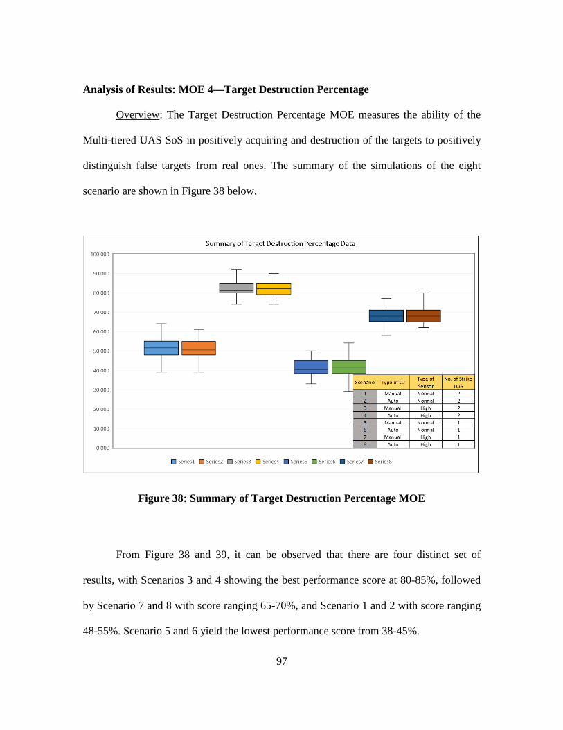
97
Analysis of Results: MOE 4—Target Destruction Percentage
Overview: The Target Destruction Percentage MOE measures the ability of the
Multi-tiered UAS SoS in positively acquiring and destruction of the targets to positively
distinguish false targets from real ones. The summary of the simulations of the eight
scenario are shown in Figure 38 below.
Figure 38: Summary of Target Destruction Percentage MOE
From Figure 38 and 39, it can be observed that there are four distinct set of
results, with Scenarios 3 and 4 showing the best performance score at 80-85%, followed
by Scenario 7 and 8 with score ranging 65-70%, and Scenario 1 and 2 with score ranging
48-55%. Scenario 5 and 6 yield the lowest performance score from 38-45%.
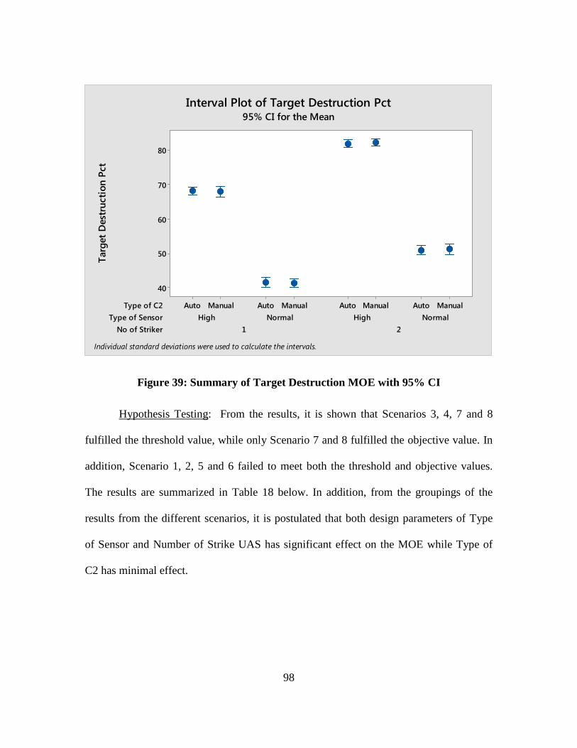
98
Figure 39: Summary of Target Destruction MOE with 95% CI
Hypothesis Testing: From the results, it is shown that Scenarios 3, 4, 7 and 8
fulfilled the threshold value, while only Scenario 7 and 8 fulfilled the objective value. In
addition, Scenario 1, 2, 5 and 6 failed to meet both the threshold and objective values.
The results are summarized in Table 18 below. In addition, from the groupings of the
results from the different scenarios, it is postulated that both design parameters of Type
of Sensor and Number of Strike UAS has significant effect on the MOE while Type of
C2 has minimal effect.
No of StrikerType of Sensor
Type of C2
21NormalHighNormalHigh
ManualAutoManualAutoManualAutoManualAuto
80
70
60
50
40
Targ
et D
estr
uctio
n Pc
tInterval Plot of Target Destruction Pct
95% CI for the Mean
Individual standard deviations were used to calculate the intervals.
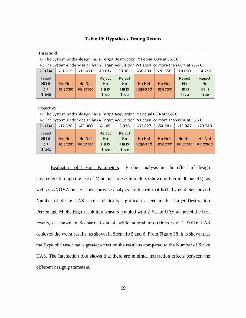
99
Table 18: Hypothesis Testing Results
Threshold H0: The System-under-design has a Target Destruction Pct equal 60% at 95% CI.
HA: The System-under-design has a Target Acquisition Pct equal or more than 60% at 95% CI Z value -11.319 -13.421 40.617 38.185 -30.489 -26.356 10.698 14.246
Reject HO if Z >
1.645
Ho Not Rejected
Ho Not Rejected
Reject Ho
Ha is True
Reject Ho
Ha is True
Ho Not Rejected
Ho Not Rejected
Reject Ho
Ha is True
Reject Ho
Ha is True
Objective H0: The System-under-design has a Target Acquisition Pct equal 80% at 95% CI.
HA: The System-under-design has a Target Acquisition Pct equal or more than 80% at 95% CI Z value -37.520 -43.380 4.189 3.376 -63.027 -54.881 -15.847 -20.248
Reject HO if Z >
1.645
Ho Not Rejected
Ho Not Rejected
Reject Ho
Ha is True
Reject Ho
Ha is True
Ho Not Rejected
Ho Not Rejected
Ho Not Rejected
Ho Not Rejected
Evaluation of Design Parameters. Further analysis on the effect of design
parameters through the use of Main and Interaction plots (shown in Figure 40 and 41), as
well as ANOVA and Fischer pairwise analysis confirmed that both Type of Sensor and
Number of Strike UAS have statistically significant effect on the Target Destruction
Percentage MOE. High resolution sensors coupled with 2 Strike UAS achieved the best
results, as shown in Scenario 3 and 4, while normal resolutions with 1 Strike UAS
achieved the worst results, as shown in Scenario 5 and 6. From Figure 38, it is shown that
the Type of Sensor has a greater effect on the result as compared to the Number of Strike
UAS. The Interaction plot shows that there are minimal interaction effects between the
different design parameters.
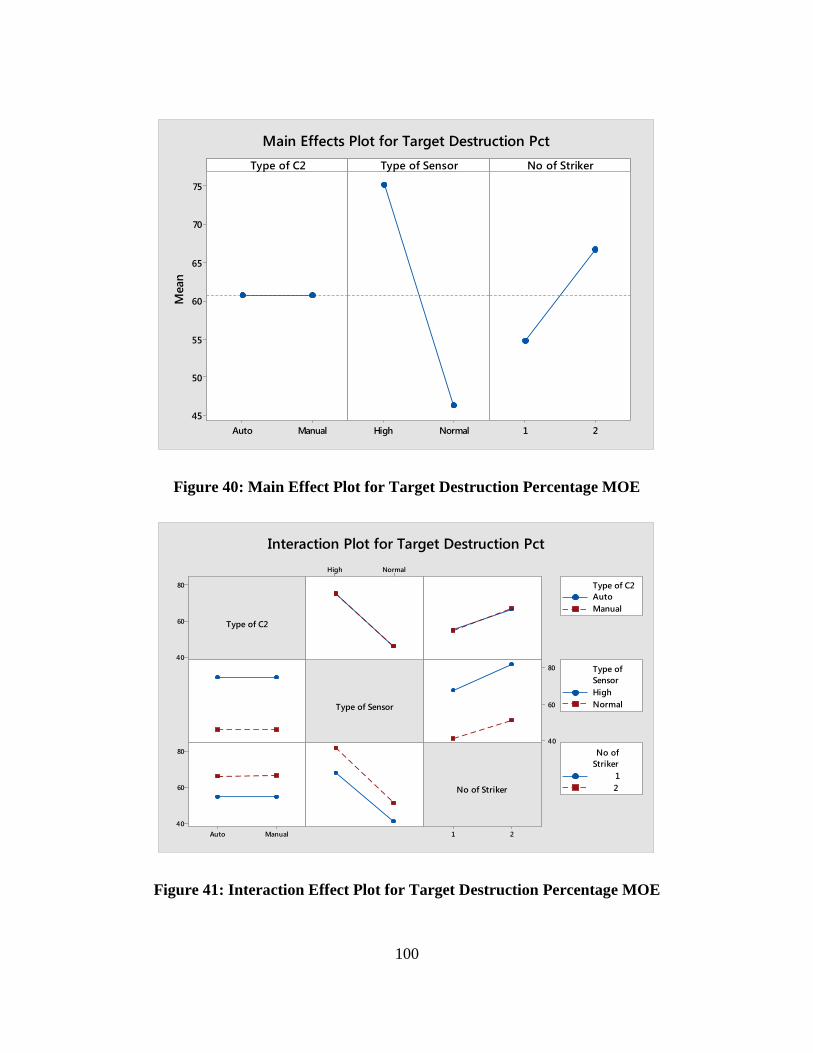
100
Figure 40: Main Effect Plot for Target Destruction Percentage MOE
Figure 41: Interaction Effect Plot for Target Destruction Percentage MOE
ManualAuto
75
70
65
60
55
50
45NormalHigh 21
Type of C2M
ean
Type of Sensor No of Striker
Main Effects Plot for Target Destruction Pct
80
60
40
21
NormalHigh
80
60
40
ManualAuto
80
60
40
Type of C2
Type of Sensor
No of Striker
AutoManual
Type of C2
HighNormal
SensorType of
12
StrikerNo of
Interaction Plot for Target Destruction Pct
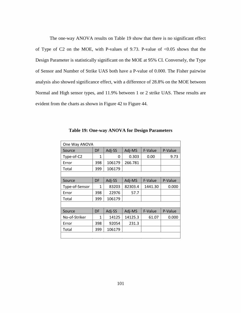
101
The one-way ANOVA results on Table 19 show that there is no significant effect
of Type of C2 on the MOE, with P-values of 9.73. P-value of <0.05 shows that the
Design Parameter is statistically significant on the MOE at 95% CI. Conversely, the Type
of Sensor and Number of Strike UAS both have a P-value of 0.000. The Fisher pairwise
analysis also showed significance effect, with a difference of 28.8% on the MOE between
Normal and High sensor types, and 11.9% between 1 or 2 strike UAS. These results are
evident from the charts as shown in Figure 42 to Figure 44.
Table 19: One-way ANOVA for Design Parameters
One Way ANOVA Source DF Adj-SS Adj-MS F-Value P-Value Type-of-C2 1 0 0.303 0.00 9.73 Error 398 106179 266.781 Total 399 106179
Source DF Adj-SS Adj-MS F-Value P-Value Type-of-Sensor 1 83203 82303.4 1441.30 0.000 Error 398 22976 57.7 Total 399 106179
Source DF Adj-SS Adj-MS F-Value P-Value No-of-Striker 1 14125 14125.3 61.07 0.000 Error 398 92054 231.3 Total 399 106179
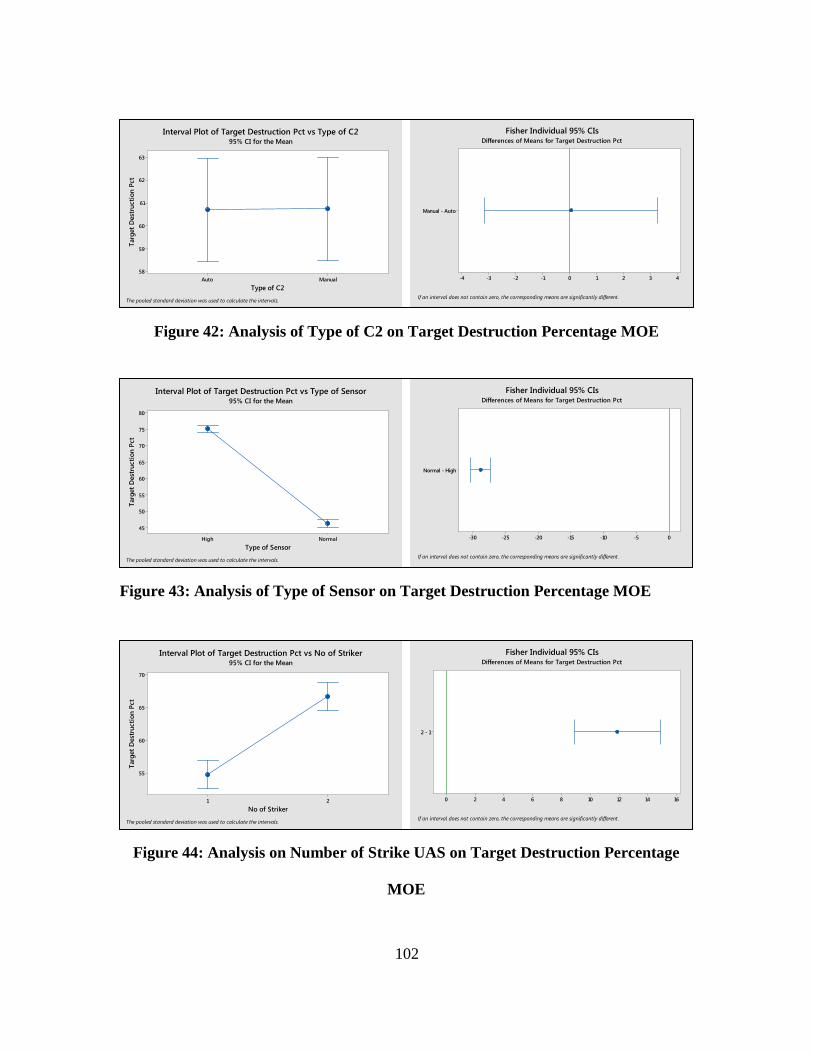
102
ManualAuto
63
62
61
60
59
58
Type of C2
Targ
et D
estr
uctio
n Pc
tInterval Plot of Target Destruction Pct vs Type of C2
95% CI for the Mean
The pooled standard deviation was used to calculate the intervals.
Manual - Auto
43210-1-2-3-4
If an interval does not contain zero, the corresponding means are significantly different.
Fisher Individual 95% CIsDifferences of Means for Target Destruction Pct
NormalHigh
80
75
70
65
60
55
50
45
Type of Sensor
Targ
et D
estr
uctio
n Pc
t
Interval Plot of Target Destruction Pct vs Type of Sensor95% CI for the Mean
The pooled standard deviation was used to calculate the intervals.
Normal - High
0-5-10-15-20-25-30
If an interval does not contain zero, the corresponding means are significantly different.
Fisher Individual 95% CIsDifferences of Means for Target Destruction Pct
21
70
65
60
55
No of Striker
Targ
et D
estr
uctio
n Pc
t
Interval Plot of Target Destruction Pct vs No of Striker95% CI for the Mean
The pooled standard deviation was used to calculate the intervals.
2 - 1
1614121086420
If an interval does not contain zero, the corresponding means are significantly different.
Fisher Individual 95% CIsDifferences of Means for Target Destruction Pct
Figure 42: Analysis of Type of C2 on Target Destruction Percentage MOE
Figure 43: Analysis of Type of Sensor on Target Destruction Percentage MOE
Figure 44: Analysis on Number of Strike UAS on Target Destruction Percentage
MOE
103
Qualitative Analysis of Results. The statistical analysis of the simulation results
for Target Destruction Percentage MOE across the 8 scenarios showed four distinct set of
results, with Scenario 3 and 4 (High resolution Sensors with 2 Strike UAS) achieving the
highest results, followed by Scenarios 7 and 8 (High resolution Sensors with 1 Strike
UAS), Scenario 1 and 2 (Normal resolution Sensors with 2 Strike UAS) and Scenarios 5
and 6 (Normal resolution Sensors with 1 Strike UAS). Only Scenarios 3 and 4 achieved
the Objective value, while Scenarios 7 and 8 achieved Threshold values. Scenarios 1, 2, 5
and 6 failed to meet Threshold requirement. From this analysis, it is determined that the
Type of Sensor must be at high resolution for the system to pass Threshold.
Further analysis on the respective design parameters confirms that the design
parameters of Type of Sensor and Number of Strike UAS have a significant effect on the
system performance on the MOE, while Type of C2 is insignificant. This is expected as
the Target Destruction Percentage MOE will require the Multi-tiered UAS SoS to 1)
positively acquire the target and 2) accurately engage and destroy it. To positively
acquire, the Type of Sensor has a large impact on the system as demonstrated in MOE 1.
In target engagement, a 2 x UAS strike package will have a better probability of kill as
compared to a 1 x UAS strike package (provided that the UAS have same system
specifications).
The analysis shows that the Type of Sensor has a more significant impact, with an
average of 28.8% difference between Normal and High resolution sensor, while the
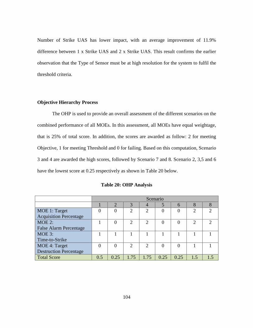
104
Number of Strike UAS has lower impact, with an average improvement of 11.9%
difference between 1 x Strike UAS and 2 x Strike UAS. This result confirms the earlier
observation that the Type of Sensor must be at high resolution for the system to fulfil the
threshold criteria.
Objective Hierarchy Process
The OHP is used to provide an overall assessment of the different scenarios on the
combined performance of all MOEs. In this assessment, all MOEs have equal weightage,
that is 25% of total score. In addition, the scores are awarded as follow: 2 for meeting
Objective, 1 for meeting Threshold and 0 for failing. Based on this computation, Scenario
3 and 4 are awarded the high scores, followed by Scenario 7 and 8. Scenario 2, 3,5 and 6
have the lowest score at 0.25 respectively as shown in Table 20 below.
Table 20: OHP Analysis
Scenario 1 2 3 4 5 6 8 8 MOE 1: Target Acquisition Percentage
0 0 2 2 0 0 2 2
MOE 2: False Alarm Percentage
1 0 2 2 0 0 2 2
MOE 3: Time-to-Strike
1 1 1 1 1 1 1 1
MOE 4: Target Destruction Percentage
0 0 2 2 0 0 1 1
Total Score 0.5 0.25 1.75 1.75 0.25 0.25 1.5 1.5
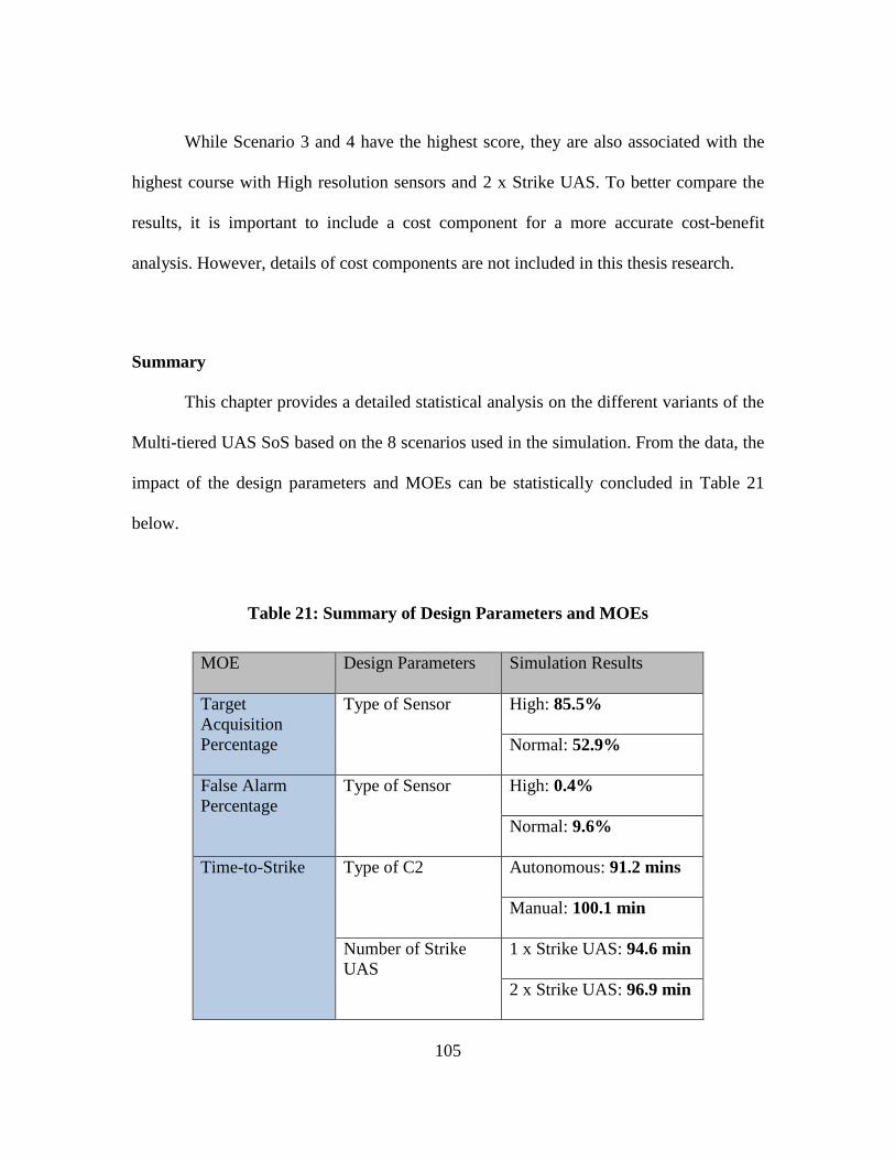
105
While Scenario 3 and 4 have the highest score, they are also associated with the
highest course with High resolution sensors and 2 x Strike UAS. To better compare the
results, it is important to include a cost component for a more accurate cost-benefit
analysis. However, details of cost components are not included in this thesis research.
Summary
This chapter provides a detailed statistical analysis on the different variants of the
Multi-tiered UAS SoS based on the 8 scenarios used in the simulation. From the data, the
impact of the design parameters and MOEs can be statistically concluded in Table 21
below.
Table 21: Summary of Design Parameters and MOEs
MOE Design Parameters Simulation Results
Target Acquisition Percentage
Type of Sensor High: 85.5%
Normal: 52.9%
False Alarm Percentage
Type of Sensor
High: 0.4%
Normal: 9.6%
Time-to-Strike Type of C2
Autonomous: 91.2 mins
Manual: 100.1 min
Number of Strike UAS
1 x Strike UAS: 94.6 min
2 x Strike UAS: 96.9 min
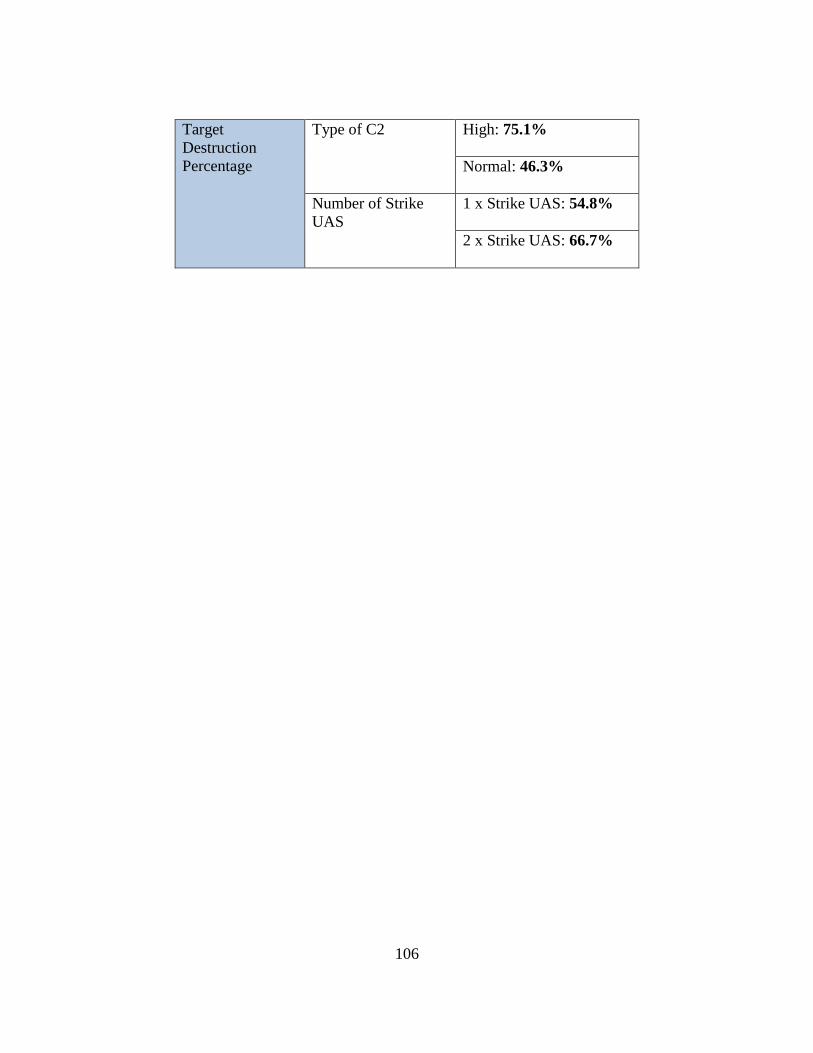
106
Target Destruction Percentage
Type of C2
High: 75.1%
Normal: 46.3%
Number of Strike UAS
1 x Strike UAS: 54.8%
2 x Strike UAS: 66.7%
107
V. Conclusions and Recommendations
Introduction of Research
This research thesis aimed to implement and assess the suitability of EA in the
evaluation of early concepts in the DoD. Specifically, the research focused on the
development of EA and dynamic models for a proposed concept of Multi-tiered UAS
which was evaluated through the use of executable DoD architectural products. Different
configurations of the proposed system were implemented in Innoslate and the effect of
different system capabilities, namely 1) Type of C2, 2) Type of Sensors, and 3) Number
of Strike UAS, were simulated through EA, and statistical analysis was used to determine
their impact on the overall system. Using the results of the simulation and analysis, the
four research questions identified in Chapter 1 are answered in the following sections.
Research Question 1: Which views of DoDAF are critical for effective construction
of EA?
To answer this question, it is important to understand the System Architecting and
System Engineering process, especially in the Concept Development Phase. During early
Concept Development, the development team focuses on answering the questions “What
will the system do?”, and “How does the system do it?”. To achieve this, the concept
development team focuses on high level system operational and functional design and
analysis, which forms the foundations of EA. In addition, during the early Concept
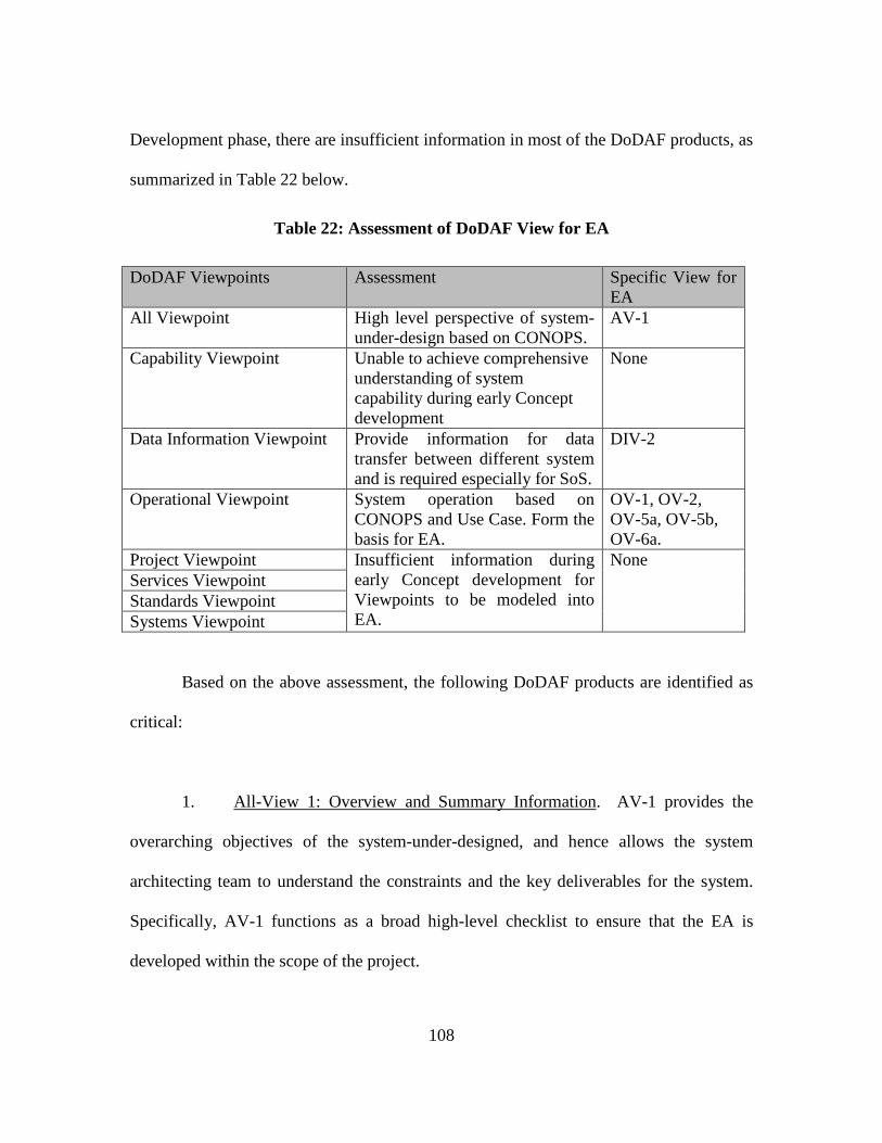
108
Development phase, there are insufficient information in most of the DoDAF products, as
summarized in Table 22 below.
Table 22: Assessment of DoDAF View for EA
DoDAF Viewpoints Assessment Specific View for EA
All Viewpoint High level perspective of system-under-design based on CONOPS.
AV-1
Capability Viewpoint Unable to achieve comprehensive understanding of system capability during early Concept development
None
Data Information Viewpoint Provide information for data transfer between different system and is required especially for SoS.
DIV-2
Operational Viewpoint System operation based on CONOPS and Use Case. Form the basis for EA.
OV-1, OV-2, OV-5a, OV-5b, OV-6a.
Project Viewpoint Insufficient information during early Concept development for Viewpoints to be modeled into EA.
None Services Viewpoint Standards Viewpoint Systems Viewpoint
Based on the above assessment, the following DoDAF products are identified as
critical:
1. All-View 1: Overview and Summary Information. AV-1 provides the
overarching objectives of the system-under-designed, and hence allows the system
architecting team to understand the constraints and the key deliverables for the system.
Specifically, AV-1 functions as a broad high-level checklist to ensure that the EA is
developed within the scope of the project.
109
2. Operational View 1: High-level Operational Concept Graphic. OV-1
provides the team with pictorial depiction of the system-under-design, and summarizes
the system operations within its operational premises. In addition, the OV-1 represents
the system architecting team interpretation of the system-under-design, and serves as an
important visual communication tools between the architecting team and the other
stakeholders.
3. Operational View 2: Operational Resource Flow Description. OV-2
describes the Resource Flows exchanged between operational nodes and activities. This
is critical for the design of EA, as EA operationalizes these information transfer processes
through simulation to access the effectiveness of the proposed concept.
4. Operational View 5a: Operational Activity Decomposition Tree. OV-5a
details the capabilities and operational activities of the system-under-design, organized in
a hierarchal structure. These operational activities are analogous to system functions, and
are important in the design of the system’s dynamic model. In particular, OV-5a provides
different levels of specification, and allows system architects to implement EA at an
appropriate level for concept evaluation.
5. Operational View 5b: Operational Activity Model. OV-5b provides the
context of capabilities and operational activities. Specifically, OV-5b shows the
relationship, processes and sequencing between entities, the operational activities, and the

110
information input and output between these nodes. OV-5b can be described as the overall
system processes and linkages, and serves as the backbone for the dynamic models for
EA.
6. Operational View 6a: Operational Rule Model. OV-6a details the
operational rules for the key activities nodes in the activity follow diagram. Specifically,
OV-6a describes the detailed interaction allowed between activities nodes, the activation
and deactivation of each activities and the expected outcome from the different
interactions. Hence OV-6a serves as the logic algorithm for effective EA development.
7. Data and Information View 2: Logical Data Model. DIV-2 identifies the
data and information flow between different entities within the system-under-design.
Specifically, they identify the data types, and how the data are implemented within the
system. This is essential as the data model forms the basis for information transfer
between different entities in the SoS and are implemented in EA as information linkages.
Research Question 2: What level of Operational or functional hierarchy of
component sub-systems is required for EA to be effective?
To effectively answer this question, it is important for the system architecting
team to understand the key objectives and requirements of the system-under-design (as
represented through the MOEs and MOPs), and the design parameters or configurations
to be evaluated. The level of hierarchy must be decomposed to the component sub-

111
systems level whereby the effect of the design parameters can be modeled to each
operational or functional node in the EA without overlaps and duplication.
The challenge in determining the right level of hierarchy is in achieving balance.
Too many levels of details will result in extensive modelling and system specifics
capability. This leads to a longer time and higher cost in development of the EA. At the
early conceptual development stage, many of these information, especially system
specific capabilities, are not available, and hence modeling such details are impractical
and may not provide the necessary value-add to the EA. Conversely, too little details
result in an overall simplified system models and the impact of the different
configurations are not accurately depicted through the simulation. As such, it is necessary
for the EA to sufficient level of hierarchy where the effects of the configurations
manifest, but not too many levels of details that result in unnecessary modeling and
additional time and development resources. To achieve the right level of hierarchy, the
system architect must first answer the following questions:
1. What are the key MOEs to be evaluated through the use of EA?
2. What are the operational activities that affect the MOEs identified in
Question 1?
3. What are the configuration or variables to be evaluated?
4. Can these variables be effectively represented in the operational activities
stated in Question 2? If not, more layers of hierarchy are required.
112
The research thesis methodology can be used to illustrate the process. First, the
MOEs, namely 1) Target Acquisition Percentage, 2) False Alarm Percentage, 3) Time-to-
strike duration, and 4) Target destruction, were determined. Following this, the
appropriate level of operational activities was identified. Next, the relationship between
the variables, namely 1) Type of C2, 2) Type of Sensors, and 3) Number of Strike UAS,
and the operational are established.
For example, as demonstrated in Chapter 4, it was shown that to determine the
impact of Type of Sensors on the Target Acquisition Percentage MOE, it was necessary
to go into the third level of the Operational Activity Hierarchy as shown in OV-5a. Here
the Type of Sensors design parameters specifically affect the Locate TBM(ISR) and
Confirm TBM Location Activity node, without affecting other activity nodes.
Research Question 3: How can EA be used to identify and evaluate the impact of
design parameters on MOEs and MOPs?
EA uses dynamic modeling as a basis of simulation to evaluate the impact of
design parameters on MOEs and MOPs. The EA provides the platform whereby design
parameters can be incorporated into the system-under-design and provide operational
outcomes based on the inputs to the system. As such, through the use of EA, system
architects will be able to identify changes in operational outcomes when different design
parameters are implemented. This allows system architects to identify how the system-
113
under-design behaves and operates under different design parameters, and to derive the
associated MOEs and MOPs to evaluate these outcomes.
For EA to be effective, the design parameters must be correctly associated with
the correct operational activity nodes, and the operational outcome of different design
parameters are accurately defined. This is achieved through the analysis of the design
parameters and operational activities as stated in Research Question 2 above. Next, these
relationships are designed into the dynamic models and simulated to obtain the results for
analysis on their impact on MOEs and MOPs.
Citing an example from this research, the design parameters Type of Sensors are
associated with the operational activities Locate TBM(ISR) and Confirm TBM Location
(Surveil). The operational outcomes are defined as the Probabilities of positive detection
and Probabilities of false detection. Through the implementation of EA, the design of
Type of Sensors were determined to affect MOEs of Target Acquisition Percentage and
False Alarm Percentage.
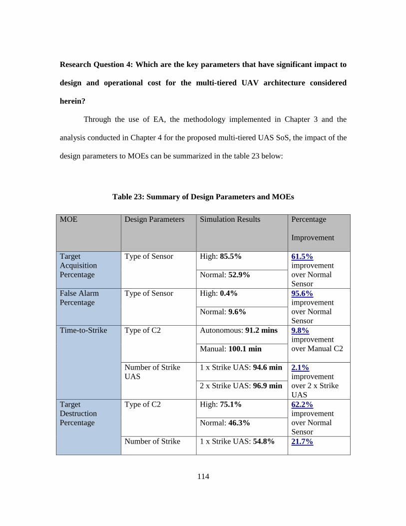
114
Research Question 4: Which are the key parameters that have significant impact to
design and operational cost for the multi-tiered UAV architecture considered
herein?
Through the use of EA, the methodology implemented in Chapter 3 and the
analysis conducted in Chapter 4 for the proposed multi-tiered UAS SoS, the impact of the
design parameters to MOEs can be summarized in the table 23 below:
Table 23: Summary of Design Parameters and MOEs
MOE Design Parameters Simulation Results Percentage
Improvement
Target Acquisition Percentage
Type of Sensor High: 85.5% 61.5% improvement over Normal Sensor
Normal: 52.9%
False Alarm Percentage
Type of Sensor
High: 0.4% 95.6% improvement over Normal Sensor
Normal: 9.6%
Time-to-Strike Type of C2
Autonomous: 91.2 mins 9.8% improvement over Manual C2 Manual: 100.1 min
Number of Strike UAS
1 x Strike UAS: 94.6 min 2.1% improvement over 2 x Strike UAS
2 x Strike UAS: 96.9 min
Target Destruction Percentage
Type of C2
High: 75.1% 62.2% improvement over Normal Sensor
Normal: 46.3%
Number of Strike 1 x Strike UAS: 54.8% 21.7%
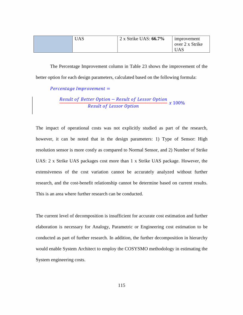
115
UAS
2 x Strike UAS: 66.7% improvement over 2 x Strike UAS
The Percentage Improvement column in Table 23 shows the improvement of the
better option for each design parameters, calculated based on the following formula:
𝑃𝑃𝑇𝑇𝑇𝑇𝐴𝐴𝑇𝑇𝑖𝑖𝑇𝑇𝑇𝑇𝑇𝑇𝑇𝑇 𝐼𝐼𝑛𝑛𝐼𝐼𝑇𝑇𝑖𝑖𝑃𝑃𝑇𝑇𝑛𝑛𝑇𝑇𝑖𝑖𝑇𝑇 =
𝑅𝑅𝑇𝑇𝑖𝑖𝐴𝐴𝑃𝑃𝑇𝑇 𝑖𝑖𝑜𝑜 𝐵𝐵𝑇𝑇𝑇𝑇𝑇𝑇𝑇𝑇𝑇𝑇 𝑂𝑂𝐼𝐼𝑇𝑇𝑖𝑖𝑖𝑖𝑖𝑖 − 𝑅𝑅𝑇𝑇𝑖𝑖𝐴𝐴𝑃𝑃𝑇𝑇 𝑖𝑖𝑜𝑜 𝐿𝐿𝑇𝑇𝑖𝑖𝑖𝑖𝑖𝑖𝑇𝑇 𝑂𝑂𝐼𝐼𝑇𝑇𝑖𝑖𝑖𝑖𝑖𝑖
𝑅𝑅𝑇𝑇𝑖𝑖𝐴𝐴𝑃𝑃𝑇𝑇 𝑖𝑖𝑜𝑜 𝐿𝐿𝑇𝑇𝑖𝑖𝑖𝑖𝑖𝑖𝑇𝑇 𝑂𝑂𝐼𝐼𝑇𝑇𝑖𝑖𝑖𝑖𝑖𝑖 𝑥𝑥 100%
The impact of operational costs was not explicitly studied as part of the research,
however, it can be noted that in the design parameters: 1) Type of Sensor: High
resolution sensor is more costly as compared to Normal Sensor, and 2) Number of Strike
UAS: 2 x Strike UAS packages cost more than 1 x Strike UAS package. However, the
extensiveness of the cost variation cannot be accurately analyzed without further
research, and the cost-benefit relationship cannot be determine based on current results.
This is an area where further research can be conducted.
The current level of decomposition is insufficient for accurate cost estimation and further
elaboration is necessary for Analogy, Parametric or Engineering cost estimation to be
conducted as part of further research. In addition, the further decomposition in hierarchy
would enable System Architect to employ the COSYSMO methodology in estimating the
System engineering costs.
116
Effectiveness of Innoslate Software in EA
As part of the thesis research, it is also important that the author provide an
evaluation of Innoslate used to develop the dynamic models for implementing EA.
Innoslate is a web-based life-cycle system engineering tool developed by SPEC
innovation. Specifically, it incorporates DoDAF architectural development tools as part
of its software package. The following sections compare the pros and cons of Innoslate
for the purpose of EA.
Benefits of Innoslate
1. DoDAF-Ready. Innoslate is equipped with DoDAF dash-board, and
maintains Template for key DoDAF architectural products, making it a useful tool
for DoDAF-related operation. In addition, the system allows entities to be reused
in different diagrams.
2. Simulation-Ready. With its in-built simulation engine, Innoslate is able to
generate simulation using the DoDAF products that were developed. In addition,
the Simulation enable both discrete-event and Monte Carlo simulations, which is
important for statistically significant evaluation of results. In addition, as the
simulation is executed directly from the DoDAF view, the system architecting
team is able to validate the accuracy of the simulation as well as communicating
the results with the key stakeholders.
117
3. Flexibility of System. The built-in simulation engine allows the user to
define the durations required for operational activities. These durations can also
be defined using pre-determined statistical functions (such as the Normal
distribution) that best represent these operational activities. In addition, Innoslate
allows the user to incorporate additional characteristics into each node through the
use of Javascript which greatly enhance the flexibility of the software for EA.
Cons of Innoslate
1. Design Limitation—Complexity. One of the key limitations in Innoslate
is in the overall complexity that the software is capable of simulating seamlessly.
As it is a web-based tool, the efficiency and performance of the software depends
on the connectivity to the internet and the overall loading on the servers. As such,
a diagram with high level of complexity and many different nodes will result in
high latency and the simulation process may be interrupted, resulting in an
ineffective run. However, for the purpose of early concept evaluation, this is not a
major limitation, since the complexity at the early stages is significantly lower.
Recommendations for Future Research
Due to time and resource limitations, the current research focused on the impact
of three different parameters on four identified MOEs. The research can be further
expanded to include the following:
118
1. Expansion of MOEs. Other MOEs critical for Mutli-tiered UAS SoS can
be evaluated, such as the 1) Range of Operations, and 2) Endurance of System.
2. Improve resolution in Entities’ capabilities. To further evaluate new
MOEs, more details can be incorporated during the development of the dynamic
models, such as 1) Fuel capacity, and 2) Operational range of each UAS tier. This
would further improve the fidelity of the EA.
3. Inclusion of Cost Component. Cost-benefit analysis is a critical part of
concept evaluation and especially estimating budgets for project. By including a
cost-analysis component as part of the research, the cost for performance can be
evaluated and the assessment on the cost benefit be done.
Summary or Significance of Research
This research implements an effective methodology through the use of EA to
evaluate the early concept of Multi-tiered UAS SoS. In particular, the research shows that
the methodology allows system architects to determine the effect of different design
parameters on overall system performance in terms of MOEs and MOPs through the use
of dynamic modeling in EA and statistical analysis. In addition, the methodology can be
further used to evaluate the following:
119
1. Determine system performance given sub-system capabilities. The
performance of the SoS can be determined when the detail capabilities of the sub-
system are available. This is similar to the research methodology, except that the
design parameters are replaced with the capabilities of the sub-system, and the
results represent the overall performance of the SoS, given the specific sub-
system.
2. Determine sub-system requirements given desired System Performance.
Conversely, the EA model can be used to determine the system specifications and
requirements of the sub-system, given the desired System Performance. In this
case, the dynamic models are simulated with different level of sub-system
capabilities to determine the sub-system requirement. For example, if the desired
performance is for the Target Acquisition Percentage MOE to achieve 98%, the
model will be simulated with different Type of Sensor capability to determine the
Probability of positive detection required for the sensor sub-system.
From the examples above, it is shown that the EA methodology provide system
architects with the tool to 1) evaluate different options, 2) understand the overall system
capability given sub-system capabilities, and 3) determine sub-system requirement given
desired system performance. These further allow the system architect to proceed with the
subsequence stages of the SE process and enable better requirement analysis and system
specification processes.

120
Appendix
Appendix A: Concept of Operations (CONOPS) for Multi-Tiered Unmanned Aircraft
System (UAS) in anti-Theater Ballistics Missile (TBM) Launcher operations.
Appendix B: AV-1 Overview and Summary Information
Appendix C: Sample Innoslate Script
121
Concept of Operations (CONOPS) for Multi-Tiered Unmanned Aircraft
System (UAS) in anti-Theater Ballistics Missile (TBM) Launcher operations.
This document articulates the concept of operations in utilizing of multi-tiered UAS system to search, track and destroy Theater Ballistics Missile (TBM) launcher within the Area of Operations. This include the execution of ISR operations to seek, track and confirm the TBM launchers, and the conduct of Dynamic Targeting and Strike to destroy the target.
1. Executive Summary Theater Ballistics Missiles (TBMs) pose significant threats to our troops, friendly forces and
civilian population within the Area of Operations (AO). The long range and lethality of TBMs, as
well as the shoot-and-scoot tactics employed by the TBM launcher units, make TBMs an
imminent threat within the AO.
To effectively counter this threat, this CONOPS focuses on the holistic use of multi-tier UAS
systems to conduct Intelligence, Surveillance and Reconnaissance (ISR) operations to search for
and track TBM launchers, and coordinate strike operations to destroy TBM launchers before they
can pose a threat to friendly forces.
This CONOPS leverages the rapid development in Unmanned Aircraft System (UAS) technology
to provide a comprehensive solution to address the threat presented by TBM systems.
Developments in UAS, and the associated sensors and payload technologies, have provided the
US military with new capabilities in key mission areas. Specifically, this CONOPS describes the
employment of different tiers of UAS within the AO, and how each UAS operates cooperatively
with one another to provide target confirmation and activate the kill-chain to destroy threats
presented by TBMs. This CONOPS provides a low-cost decision making solution that minimizes
risk by pre-emptively destroying TBM launchers through the use of the multi-tiered UAS
System-of-Systems (SoS).
122
2. Purpose
The US's UAS arsenal is comprised of numerous UAS with capabilities that ranges from small
man-portable vehicles, to medium “fighter-sized” vehicles, and large “tanker-sized” vehicles, as
well as specialized UAS with unique capabilities. These capabilities allow UAS to perform many
vital roles in military operations, including:
1) ISR
2) Strike
3) Protection
4) Sustainment
5) Movement and Maneuvering
6) Command and Control
The Multi-tiered UAS architecture aims to deliver a synergistic battlefield effect in the search,
track and destroy operations related to TBMs, through using an integrated UAS solution that
employs different tiers of UAS, to maximize mission effectiveness, while minimizing operational
risks and operating costs. This ISR SoS enables cooperative operations among different groups of
UAS within the same AO to identify, confirm targets, and to assign tasks among differing UAS
groups to maximize mission effectiveness and efficiency.
3 Background
The proliferation of TBM technology and launcher systems by our adversaries presents a
substantial threat to military operations in various regions around the world. Specifically, TBM
systems provide our adversary with relatively cheap and accurate stand-off capabilities with a
potential for highly lethal munitions. Different warheads (such as high-explosive, nuclear or
chemical) within the TBM system provide our adversaries with great degree of versatility during
combat, while potentially lowering the effectiveness of friendly forces. To maintain our military
123
edge in contested environments, it is necessary that a low-cost solution with minimal risk be
developed to pre-emptively destroy TBM launchers.
4 Future Environment
As TBM components become cheaper to produce and grow more technologically advanced, the
threat posed by TBM systems will continue to increase and grow more complex[1]. Current
trends indicate that adversary TBM systems are becoming more mobile, survivable, reliable, and
accurate while also achieving longer ranges. In addition, pre-launch survivability is also likely to
increase as adversaries denial and deception measures improve.
Similarly, UAS technology will continue to evolve and new capabilities will be developed for
UAS operations. In this regard, the USAF Unmanned Aircraft Systems Flight Plan 2009-2047
and the US Army Roadmap for UAS 2010-2035 setup the potential UAS development and
employment for the Air Force and Army Respectively. Currently employment of UAS within the
US military are executed along stove-piped functional lines, with each operational unit operating
specific classes of UAS for their respective mission. It is anticipated that future UAS employment
will require a more synergistic deployment of integrated multi-tiered UAS to maximize mission
effectiveness while minimizing risks and operating costs.
[1] “Ballistics and Cruise Missiles Threat”, NASIC, 2013
5 Concept Time Frame/ Scope
The successful execution of the CONOPS requires—1) Organizational Structure to vest the
Combatant Commander with the Command and Control (C2) authority of different tiers of UAS,
2) Technological Development in Cooperative UAS technology, and 3) UAS sensors and payload
systems to deliver the required Capabilities.
124
The ISR SoS is expected to be fielded in 2026. The timeline goal for the development of this SoS
will drive the overall schedule of the program. The Timeline goal for Technological development
is expected to be completed within 10 years, by the year 2026, with the respective Organizational
Structure approved within the same time-frame. Current UAS sensors and payloads are deemed
capable of fulfilling the operational requirements as stipulated by the CONOPS.
6 Military Need Statement
Rapid improvements of TBM technology and increases in weapons proliferation to non-allied
nations have resulted in new and constantly changing threats to friendly forces. The high
accuracy of many TBM systems allow them to inflict serious damages from significant stand-off
distances, even when the missiles are armed with only conventional warheads. To further
compound the problem, TBM launchers employ a shoot-and-scoot technique which makes
counter-TBM operations challenging. To address this threat, the military needs to have a
capability that can preemptively seek and destroy TBM launchers. This multi-tiered UAS SoS
provides the capability to maintain persistent situational awareness over a designated area to
search and locate possible TBM Launchers, and dynamically target and strike these TBM
Launchers with minimal cost, or risk to personnel.
7 Central Idea
The multi-tiered UAS SoS focuses on the efficient employment of different groups of UAS to
maintain persistent situational awareness over the AO, to seek and identify possible TBM
Launchers, and to dynamically direct targeting and strike operations. It leverages the capabilities
of different groups of UAS and sensor systems to achieve a system capable of optimizing UAS
employment for mission effectiveness, while minimizing operational cost and risk. Specifically,
the multi-tiered UAS SoS will need to employ cooperative control among various UAS groups in
the AO to assign roles and plan safe routes for ingress and egress.
a. Larger tiers UASs (Group 4 and 5):
iii. Persistent ISR. The larger tiers of UASs have greatest range, endurance,
airspeed and altitude capabilities in the family of UAS. As such, these UAS
are typically employed to conduct persistent ISR over the AO. They will be
125
equipped with the necessary sensors to identify possible Surface-to-Air
(SAM) sites and possible TBM Launchers in the AO.
iv. Dynamic Strike. These groups of UAS are also capable of carrying kinetic
weapons, and could be loaded with the necessary munitions to provide a
dynamic strike capability.
b. Smaller tiers UASs (Group 1 and 2):
iii. Target Verification. The smaller UAS groups have a smaller footprint are
used for target verification and can be equipped with Automatic Target
Recognition (ATR) software to determine phases of TBM launcher
deployment.
iv. Battle Damage Assessment (BDA). These UAS groups will also be used to
perform BDA after the conclusion of the dynamic strike to confirm mission
success.
8 Users and Stakeholders
Secretary of Defense and Office of Secretary of Defense (OSD): Responsible for determining and
approval of UAS policies for UAS employment within the US military.
Chief of Staff: Approval for the Assets to be deployed into the Operational Theater. They are
responsible for strategic planning and to balance operational need across different battle fronts to
allocate assets to the Combat Commander.
Combatant Commander: The Combat Commander is responsible for the overall mission success
in the Operational Theater. He determines and requests assets to be deployed in the Operational
Theater and is vested with the authority to designate assets and assign forces for specific missions
in theater.
126
Mission Commander: Operator of multi-tiered UAS SoS who is responsible for all local UAS
assets.
Organic UAS Unit: The organic UAS unit is responsible for the tactical execution of launch,
recovery and tactical control of the UAS within the AO. They receive orders and taskings from
the Combat Commanders in the planning and execution of tactical execution. The organic UAS
unit is also responsible for the maintenance and support of the UAS under their responsibility to
sustain UAS operations within the AO throughout the mission.
Federal Aviation Administration (FAA): The FAA is responsible for the design of aviation
policies that guide the usage of UASs in the National Air Space. In particular, FAA sets air-
worthiness criteria for Group 4 and 5 UAS operations and the airspace usage regulations for these
UAS. The UASs will be flown within US for training purpose, and AOs are typically out-of-
country. In addition, Group 4 and 5 UASs will need to pass the FAA air-worthiness requirement.
SPO: System Program Office – Agency responsible for the long-term sustainment, part
revitalization and upgrade programs for a specific MDS.
JFACC: Joint Forces Air Component Commander – Individual in command of the AOC and
responsible for all air operations in the AOR.
JFGCC: Joint Forces Ground Component Commander – Individual in command of the and
responsible for all air operations in the AOR.This person is responsible for identifying and
allocating access to the multi-tiered SoS for all ground forces in the AOR.
9 Policies
Policies governing the use of UAS can be found in the following documents:
a. OSD FY2011-2036 Unmanned Systems Integrated Roadmap, OSD AT&L, 2011
b. OSD Quadrennial Roles and Missions Review UAS ISR Report, USD (I) 2008
c. Joint UAS Center of Excellence (JCOE) Concept of Operation for Unmanned Aircraft
Systems, JROCM 229-08, 25 November 2008
d. JP 3-30, Command and Control for Joint Air Operations, 12 January 2010
127
e. USAF Unmanned Aircraft Flight Plan 2009-2047
f. U.S. Army Unmanned Aircraft Systems Roadmap 2010-2035
10 Mission Operation Scenario
One scenario focusing on the use of different UAS groups consists of a requirement to search,
track and destroy TBM Launchers and is elaborated below to illustrate the cooperative nature of
the system.
Background: In a conflict between an allied country and its non-allied neighbor over a resource-
rich off-shore area. The non-allied country is threatening military response if the AO is not
completely vacated by the allied country. The non-allied country is equipped with several SAM
sites and TBM launchers.
Mission Operations: The Combatant Commander aims to search, track and destroy the TBMs
through the effective use of multiple UAS groups via the multi-tiered UAS SoS.
1. Group 4/5 ISR UAS equipped with Electronic Intelligence (ELINT) sensors and
Synthetic Aperture Radar (SAR), patrol along the edge of ally’s airspace to classify the
SAM sites, build the Electronic Order of Battle (EOB) and perform coherent change
detection. These ISR operations are executed over several weeks to detect bunker sites.
2. Group 1 UAS, equipped with EO sensors, monitor the area around bunker sites and are
guided by Multi-tiered UAS SoS.
3. Group 1 UAS is also equipped with ATR to determine phases of TBM deployment.
4. Upon detection of a “fueling phase”, the SoS is notified.
5. The nearest un-tasked Group 4/5 UAS with appropriate weapon payload is identified and
target is assigned to the UAS.
6. Armed Group 4/5 arrives and strike TBM launcher after confirmation by Combat
Commander.
7. Group 1 UAS performs BDA via EO sensors and ATR software.
11 Capabilities
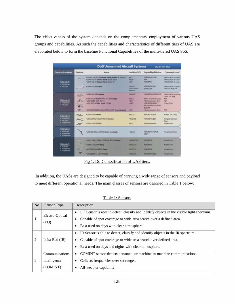
128
The effectiveness of the system depends on the complementary employment of various UAS
groups and capabilities. As such the capabilities and characteristics of different tiers of UAS are
elaborated below to form the baseline Functional Capabilities of the multi-tiered UAS SoS.
Fig 1: DoD classification of UAS tiers.
In addition, the UASs are designed to be capable of carrying a wide range of sensors and payload
to meet different operational needs. The main classes of sensors are descried in Table 1 below:
Table 1: Sensors
No Sensor Type Description
1
Electro-Optical
(EO)
• EO Sensor is able to detect, classify and identify objects in the visible light spectrum.
• Capable of spot coverage or wide area search over a defined area.
• Best used on days with clear atmosphere.
2
Infra-Red (IR)
• IR Sensor is able to detect, classify and identify objects in the IR spectrum.
• Capable of spot coverage or wide area search over defined area.
• Best used on days and nights with clear atmosphere.
3
Communications
Intelligence
(COMINT)
• COMINT sensor detects personnel or machine-to-machine communications.
• Collects frequencies over set ranges.
• All-weather capability.
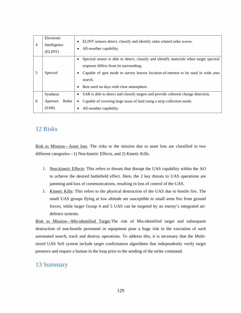
129
4
Electronic
Intelligence
(ELINT)
• ELINT sensors detect, classify and identify radar related radio waves.
• All-weather capability.
5
Spectral
• Spectral sensor is able to detect, classify and identify materials when target spectral
response differs from its surrounding.
• Capable of spot mode to survey known location-of-interest to be used in wide area
search.
• Best used on days with clear atmosphere.
6
Synthetic
Aperture Radar
(SAR)
• SAR is able to detect and classify targets and provide coherent change detection.
• Capable of covering large areas of land using a strip collection mode.
• All-weather capability.
12 Risks
Risk to Mission—Asset loss. The risks to the mission due to asset loss are classified in two
different categories—1) Non-kinetic Effects, and 2) Kinetic Kills.
1. Non-kinetic Effects: This refers to threats that disrupt the UAS capability within the AO
to achieve the desired battlefield effect. Here, the 2 key threats to UAS operations are
jamming and loss of communications, resulting in loss of control of the UAS.
1. Kinetic Kills: This refers to the physical destruction of the UAS due to hostile fire. The
small UAS groups flying at low altitude are susceptible to small arms fire from ground
forces; while larger Group 4 and 5 UAS can be targeted by an enemy’s integrated air-
defence systems.
Risk to Mission—Mis-identified Target.The risk of Mis-identified target and subsequent
destruction of non-hostile personnel or equipment pose a huge risk in the execution of such
automated search, track and destroy operations. To address this, it is necessary that the Multi-
tiered UAS SoS system include target confirmation algorithms that independently verify target
presence and require a human in the loop prior to the sending of the strike command.
13 Summary
130
The multi-tiered UAS SoS will provide the US military with the new capability to almost
completely automate the capability of preemptively addressing threats posed by TBMs. In
addition, the system represents a paradigm shift from the current mode of UAS employment
whereby UAS are deployed along stove-piped functional lines and enables the synergistic
deployment of integrated multi-tiered UAS systems. This will maximize mission effectiveness
while minimizing risks and operating costs through the optimal use of different UAS groups to
achieve desired battlefield effects.
14 CONOPS Development Team
Capt Andrew Roberts
Ms. Lidia Toscano
MAJ Zhongwang, Chua
Capt Nicholas Gilbert
131
AV-1 Overview and Summary Information UAS Multi-Tier Overview and Summary
1 Architecture Description Identification
1.1 Name of Architecture Project
Multi-tiered Unmanned Aircraft System (UAS) System-of-Systems (SoS) for Theater-Ballistics
Missile (TBM) Launcher strike.
2.2 Architect Leading Project
Zhongwang Chua is the Chief Architect leading the project development.
2.3 Organization Developing the Architecture
Group 4 Architecting
2.4 Assumptions and Constraints
• The System is able to interact securely with the different tiers of UAS system.
• Mission Commander is vested with the authority to Command and Control UASs deployed
within the AO and has the authority to issue Strike command.
• All UAS systems are in the Operations and Sustainment phase of the life-cycle.
• All UAS systems are in working order and have trained personnel to operate them.
• The Group 1 UAS has sufficient camouflage, altitude climbing, or other means of staying
hidden from human guards.
2.5 Approval Authority
Lt Col Thomas Ford
132
2.6 Date Completed
15 March 2016
2.7 Level of Effort and Projected / Actual Cost to Develop the Architecture
The actual cost of this architecture is merely the blood, sweat, and tears of the four members
striving to graduate on time with outstanding grades. No additional financial burden is placed on
the institution due to the creation of this architecture.
3 Scope: Architecture Viewpoints, Models and Views
3.1 Viewpoints and Models Developed
Various DoDAF viewpoints and models will be utilized in the development of the Multi-tiered
UAS SoS architecture. DoDAF viewpoints include:
• AV-1: Overview and Summary Information
• AV-2: Integrated Dictionary
• OV-1: High Level Operational Concept Graphic
• CV-2: Capability Taxonomy
• OV-4: Organizational Relationships Chart
• OV-5a: Operational Activity Decomposition Tree
• CV-6: Capability to Operational Activities Mapping
• OV-5b: Operational Activity Model
• DIV-2: Logical Data Model
• OV-2: Operational Resource Flow Description
• OV-3: Operational Resource Flow Matrix
• OV-6a: Operational Rules Model
• OV-6b: State Transition Description
• OV-6c: Event-Trace Description
• SV-1: Systems Interface Description
• SV-4: Systems Functionality Description

133
• SV-5a: Operational Activity to Systems Function Traceability Matrix
• SV-7: System Measures Matrix
• Multi-tiered UAS SoS Software Simulation
CONOPS and Use Cases will also be developed to ensure coverage of all major details.
3.2 Time Frames Addressed
The successful execution of the system architecture requires— 1) Organizational Structure to vest
the Combatant Commander with the Command and Control (C2) authority of different tiers of
UAS, 2) Technological Development in Cooperative UAS technology, and 3) UAS sensors and
payload systems to deliver the required Capabilities.
The Multi-tiered UAS SoS is expected to be fielded in 2031. The timeline goal for the
development of Multi-tiered UAS SoS will drive the overall schedule of the program. The
Timeline goal for Technological development is expected to be completed within 5 years, by the
year 2031, with the respective Organizational Structure approved within the same time-frame.
Current UAS sensors and payloads are deemed capable of fulfilling the operational requirements
as stipulated by the CONOPS.
3.3 Organizations Involved
Secretary of Defense and Office of Secretary of Defense (OSD): Responsible for determining and
approval of UAS policies for UAS employment within the US military.
Chief of Staff: Approval for the Assets to be deployed into the Operational Theater. They are
responsible for strategic planning and to balance operational need across different battle fronts to
allocate assets to the Combat Commander.
Combatant Commander: The Combat Commander is responsible for the overall mission success
in the Operational Theater. He determines and requests assets to be deployed in the Operational
Theater and is vested with the authority to designate assets and assign forces for specific missions
in theater.
134
Mission Commander: Operator of Multi-tiered UAS SoS who is responsible for all local UAS
assets.
Organic UAS Unit: The organic UAS unit is responsible for the tactical execution of launch,
recovery and tactical control of the UAS within the AO. They receive orders and taskings from
the Combat Commanders in the planning and execution of tactical execution. The organic UAS
unit is also responsible for the maintenance and support of the UAS under their responsibility to
sustain UAS operations within the AO throughout the mission.
Federal Aviation Administration (FAA): The FAA is responsible for the design of aviation
policies that guide the usage of UASs in the National Air Space. In particular, FAA sets air-
worthiness criteria for Group 4 and 5 UAS operations and the airspace usage regulations for these
UAS. The Multi-tiered UAS SoS system will be flown within US for training purpose, and AOs
are typically out-of-country. In addition, Group 4 and 5 UASs will need to pass the FAA air-
worthiness requirement.
SPO: System Program Office – Agency responsible for the long-term sustainment, part
revitalization and upgrade programs for a specific MDS (to include Multi-tiered UAS SoS)
JFACC: Joint Forces Air Component Commander – Individual in command of the AOC and
responsible for all air operations in the AOR.
JFGCC: Joint Forces Ground Component Commander – Individual in command of and
responsible for all ground operations in the AOR. This person is responsible for identifying and
allocating access to the Multi-tiered UAS SoS System for all ground forces in the AOR.
4 Purpose and Perspective
Problem
Rapid improvements of TBM technology and increases in weapons proliferation to non-allied
nations have resulted in new and constantly changing threats to friendly forces. The high
135
accuracy of many TBM systems allow them to inflict serious damages from significant stand-off
distances, even when the missiles are armed with only conventional warheads. To further
compound the problem, TBM launchers employ a shoot-and-scoot technique which makes
counter-TBM operations challenging.
Need
To address this threat, the military needs to have a capability that can preemptively seek and
destroy TBM launchers. Multi-tiered UAS SoS provides the capability to maintain persistent
situational awareness over a designated area to search and locate possible TBM Launchers, and
dynamically target and strike these TBM Launchers with minimal cost, or risk to personnel.
Purpose of Multi-tiered UAS SoS
The US's UAS arsenal is comprised of numerous UAS with capabilities that ranges from small
man-portable vehicles, to medium “fighter-sized” vehicles, and large “tanker-sized” vehicles, as
well as specialized UAS with unique capabilities. These capabilities allow UAS to perform many
vital roles in military operations, including:
1) ISR
2) Strike
3) Protection
4) Sustainment
5) Movement and Maneuvering
The system architecture aims to deliver a synergistic battlefield effect in the search, track and
destroy operations related to TBMs, through using an integrated UAS solution that employs
different tiers of UAS, to maximize mission effectiveness, while minimizing operational risks and
operating costs. Multi-tiered UAS SoS enables cooperative operations among different groups of
UAS within the same AO to identify, confirm targets, and to assign tasks among differing UAS
groups to maximize mission effectiveness and efficiency.
136
5 Context
5.1 Mission
Different Tiers of UASs will be deployed within the same AO to achieve the desired battlefield
effect and mission success. In theater, UASs will be equipped with different sensors and software
so that they can fulfill different mission roles. In particular, this architecture focuses on finding,
tracking, and destroying TBMs efficiently and effectively through the use of the Multi-tiered
UAS SoS system.
5.2 Doctrine, Goals, and Vision
The System provides the Combat Commander with a full suite of aerial capabilities applied
automatically to achieve mission success. In particular, UAS systems:
• Reduce risks to ground troops.
• Reduce command workload while sustaining persistent operations by automating what
can be automated.
• Increase capabilities for extended range and stand-off operations.
5.3 Concepts of Operations/Scenarios
The system focuses on the efficient employment of different groups of UAS to maintain
persistent situational awareness over the AO, to seek and identify possible TBM Launchers, and
to dynamically direct targeting and strike operations. It leverages the capabilities of different
groups of UAS and sensor systems to achieve a system capable of optimizing UAS employment
for mission effectiveness, while minimizing operational cost and risk. Additionally, the system
will be the central node in a system-of-systems employing cooperative control among various
UAS groups in the AO to assign roles and plan safe routes for ingress and egress.
a. Larger tiers UASs (Group 4 and 5):
i. Persistent ISR. The larger tiers of UASs have greatest range, endurance, airspeed and
altitude capabilities in the family of UAS. As such, these UAS are typically
137
employed to conduct persistent ISR over the AO. They will be equipped with the
necessary sensors to identify possible Surface-to-Air (SAM) sites and possible TBM
Launchers in the AO.
ii. Dynamic Strike. These groups of UAS are also capable of carrying kinetic weapons,
and could be loaded with the necessary munitions to provide a dynamic strike
capability.
b. Smaller tiers UASs (Group 1 and 2):
i. Target Verification. The smaller UAS groups have a smaller footprint are used for
target verification and can be equipped with Automatic Target Recognition (ATR)
software to determine phases of TBM launcher deployment.
ii. Battle Damage Assessment (BDA). These UAS groups will also be used to perform
BDA after the conclusion of the dynamic strike to confirm mission success.
5.4 Information Assurance Context
The same information assurance criteria for individual UAS tiers will apply because there are no
new information streams, only new methods for automating them.
5.5 Linkages to Other Architectures
This architecture is linked with the ISR and each UAS group's respective architecture.
6 Architecture Development Schedule
13 Jan 2016 - Overarching CONOPS, Use Cases, AV-1, AV2
20 Jan 2016 - OV-5a, CV-2, OV-1, OV-4
27 Jan 2016 - CV-6, OV5b, DIV-2
17 Feb 2016 - OV-2, OV-3, OV-6a, b, c
24 Feb 2016 - SV-1, SV-4, SV-5a
2 Mar 2016 - SV-7, Multi-tiered UAS SoS Software Simulation

138
7 Findings
This section will be developed as the architecture development progresses.
7.1 Analysis Results
Ownership and Responsibility
a. Who owns the asset?
- The AOC will own this asset.
b. Who commands UAS employment?
- The Multi-tiered UAS SoS shall be supervised by the Mission Commander at all
times.
c. Who has the final say in this system?
- Mission Commander.
d. What level is required for the implementation of proposed architecture?
- Office Secretary of Defense through JCIDS process
e. Does funding have an impact on employment? (who pays for it?)
- Yes.
Technical Feasibility
a. What are the technical issues affecting integration between different fleet (such as
communication datalink, commonality of software data systems)?
- Flight Planning Algorithm
- Strike Target Flight Maneuvers
- Intelligence Gathering
- BDA Image Processing
- Bandwidth
- Secure Communications
- Communicate Intelligence feed simultaneously between Mission Commander,
AOC, and Ground Forces
Deployment Guidelines
a. What should the Rules of Engagement (ROEs) be?

139
- The system will have the mission parameters altered by the Mission Commander
in order to tailor the guidance parameters in order to maximize flexibility. The
Mission Commander is kept in the loop for this reason and to ensure that a
human always makes the decision to launch munitions.
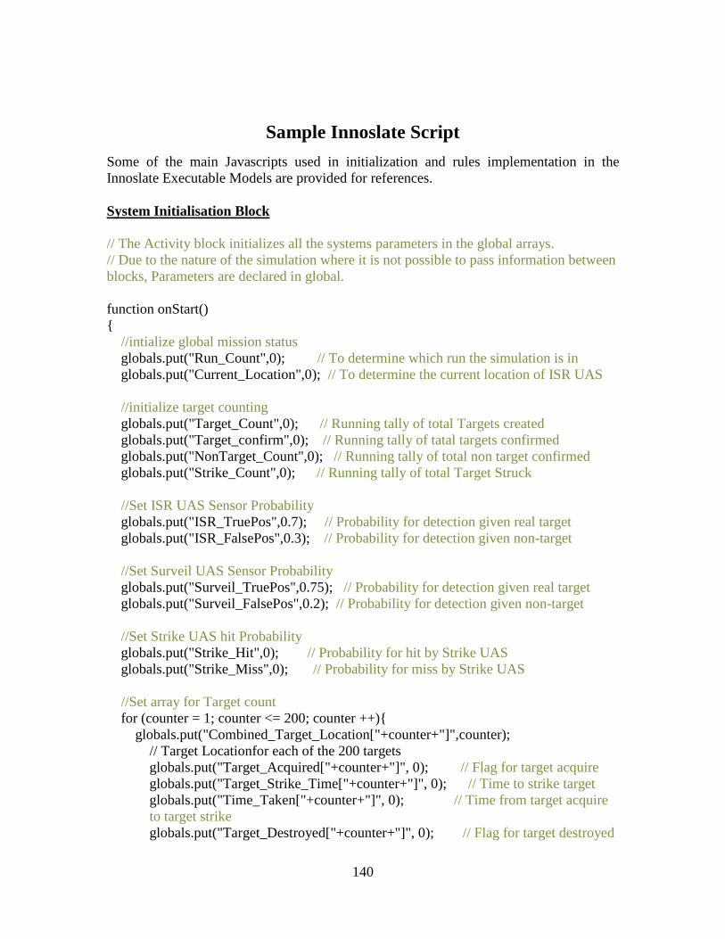
140
Sample Innoslate Script
Some of the main Javascripts used in initialization and rules implementation in the Innoslate Executable Models are provided for references. System Initialisation Block // The Activity block initializes all the systems parameters in the global arrays. // Due to the nature of the simulation where it is not possible to pass information between blocks, Parameters are declared in global.
function onStart() { //intialize global mission status globals.put("Run_Count",0); // To determine which run the simulation is in globals.put("Current_Location",0); // To determine the current location of ISR UAS
//initialize target counting globals.put("Target_Count",0); // Running tally of total Targets created globals.put("Target_confirm",0); // Running tally of tatal targets confirmed globals.put("NonTarget_Count",0); // Running tally of total non target confirmed globals.put("Strike_Count",0); // Running tally of total Target Struck
//Set ISR UAS Sensor Probability globals.put("ISR_TruePos",0.7); // Probability for detection given real target globals.put("ISR_FalsePos",0.3); // Probability for detection given non-target
//Set Surveil UAS Sensor Probability globals.put("Surveil_TruePos",0.75); // Probability for detection given real target globals.put("Surveil_FalsePos",0.2); // Probability for detection given non-target
//Set Strike UAS hit Probability globals.put("Strike_Hit",0); // Probability for hit by Strike UAS globals.put("Strike_Miss",0); // Probability for miss by Strike UAS //Set array for Target count for (counter = 1; counter <= 200; counter ++){ globals.put("Combined_Target_Location["+counter+"]",counter);
// Target Locationfor each of the 200 targets globals.put("Target_Acquired["+counter+"]", 0); // Flag for target acquire globals.put("Target_Strike_Time["+counter+"]", 0); // Time to strike target globals.put("Time_Taken["+counter+"]", 0); // Time from target acquire to target strike
globals.put("Target_Destroyed["+counter+"]", 0); // Flag for target destroyed
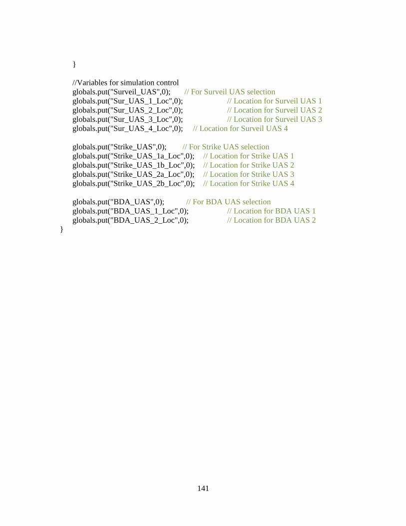
141
} //Variables for simulation control globals.put("Surveil_UAS",0); // For Surveil UAS selection globals.put("Sur_UAS_1_Loc",0); // Location for Surveil UAS 1 globals.put("Sur_UAS_2_Loc",0); // Location for Surveil UAS 2 globals.put("Sur_UAS_3_Loc",0); // Location for Surveil UAS 3 globals.put("Sur_UAS_4_Loc",0); // Location for Surveil UAS 4 globals.put("Strike_UAS",0); // For Strike UAS selection globals.put("Strike_UAS_1a_Loc",0); // Location for Strike UAS 1 globals.put("Strike_UAS_1b_Loc",0); // Location for Strike UAS 2 globals.put("Strike_UAS_2a_Loc",0); // Location for Strike UAS 3 globals.put("Strike_UAS_2b_Loc",0); // Location for Strike UAS 4 globals.put("BDA_UAS",0); // For BDA UAS selection globals.put("BDA_UAS_1_Loc",0); // Location for BDA UAS 1 globals.put("BDA_UAS_2_Loc",0); // Location for BDA UAS 2
}
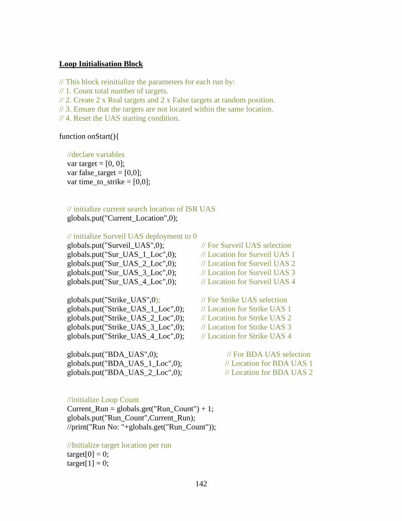
142
Loop Initialisation Block // This block reinitialize the parameters for each run by: // 1. Count total number of targets. // 2. Create 2 x Real targets and 2 x False targets at random position. // 3. Ensure that the targets are not located within the same location. // 4. Reset the UAS starting condition. function onStart(){ //declare variables var target = [0, 0]; var false_target = [0,0]; var time_to_strike = [0,0]; // initialize current search location of ISR UAS globals.put("Current_Location",0); // initialize Surveil UAS deployment to 0 globals.put("Surveil_UAS",0); // For Surveil UAS selection globals.put("Sur_UAS_1_Loc",0); // Location for Surveil UAS 1 globals.put("Sur_UAS_2_Loc",0); // Location for Surveil UAS 2 globals.put("Sur_UAS_3_Loc",0); // Location for Surveil UAS 3 globals.put("Sur_UAS_4_Loc",0); // Location for Surveil UAS 4 globals.put("Strike_UAS",0); // For Strike UAS selection globals.put("Strike_UAS_1_Loc",0); // Location for Strike UAS 1 globals.put("Strike_UAS_2_Loc",0); // Location for Strike UAS 2 globals.put("Strike_UAS_3_Loc",0); // Location for Strike UAS 3 globals.put("Strike_UAS_4_Loc",0); // Location for Strike UAS 4 globals.put("BDA_UAS",0); // For BDA UAS selection globals.put("BDA_UAS_1_Loc",0); // Location for BDA UAS 1 globals.put("BDA_UAS_2_Loc",0); // Location for BDA UAS 2 //initialize Loop Count Current_Run = globals.get("Run_Count") + 1; globals.put("Run_Count",Current_Run); //print("Run No: "+globals.get("Run_Count")); //Initialize target location per run target[0] = 0; target[1] = 0;
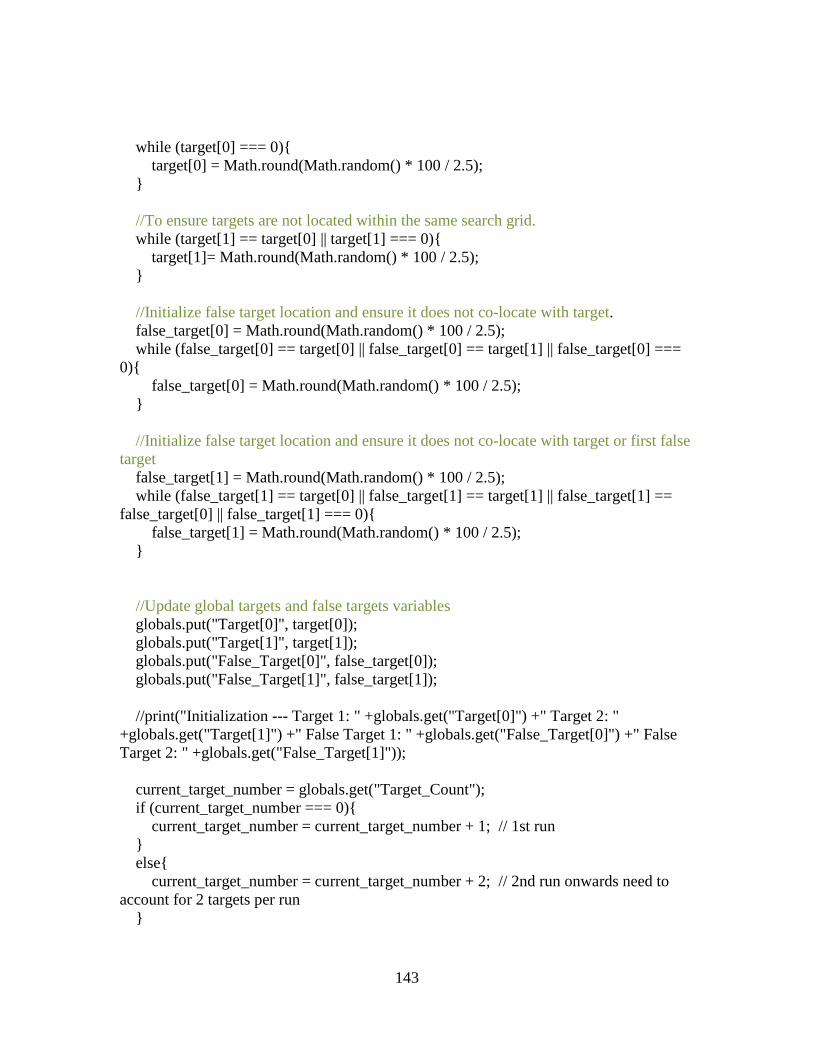
143
while (target[0] === 0){ target[0] = Math.round(Math.random() * 100 / 2.5); } //To ensure targets are not located within the same search grid. while (target[1] == target[0] || target[1] === 0){ target[1]= Math.round(Math.random() * 100 / 2.5); } //Initialize false target location and ensure it does not co-locate with target. false_target[0] = Math.round(Math.random() * 100 / 2.5); while (false_target[0] == target[0] || false_target[0] == target[1] || false_target[0] === 0){ false_target[0] = Math.round(Math.random() * 100 / 2.5); } //Initialize false target location and ensure it does not co-locate with target or first false target false_target[1] = Math.round(Math.random() * 100 / 2.5); while (false_target[1] == target[0] || false_target[1] == target[1] || false_target[1] == false_target[0] || false_target[1] === 0){ false_target[1] = Math.round(Math.random() * 100 / 2.5); } //Update global targets and false targets variables globals.put("Target[0]", target[0]); globals.put("Target[1]", target[1]); globals.put("False_Target[0]", false_target[0]); globals.put("False_Target[1]", false_target[1]); //print("Initialization --- Target 1: " +globals.get("Target[0]") +" Target 2: " +globals.get("Target[1]") +" False Target 1: " +globals.get("False_Target[0]") +" False Target 2: " +globals.get("False_Target[1]")); current_target_number = globals.get("Target_Count"); if (current_target_number === 0){ current_target_number = current_target_number + 1; // 1st run } else{ current_target_number = current_target_number + 2; // 2nd run onwards need to account for 2 targets per run }

144
globals.put("Combined_Target_Location["+ current_target_number +"]",target[0]); globals.put("Target_Count",current_target_number); current_target_number = globals.get("Target_Count") + 1; globals.put("Combined_Target_Location["+ current_target_number +"]",target[1]); globals.put("Target_Count",current_target_number); //reset the target count to correspond to the 1st target of current run current_target_number = globals.get("Target_Count") - 1; globals.put("Target_Count",current_target_number); }
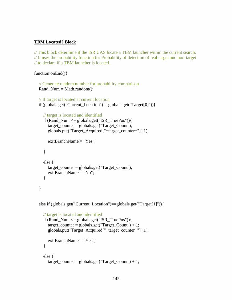
145
TBM Located? Block // This block determine if the ISR UAS locate a TBM launcher within the current search. // It uses the probability function for Probability of detection of real target and non-target // to declare if a TBM launcher is located. function onEnd(){ // Generate random number for probability comparison Rand_Num = Math.random(); // If target is located at current location if (globals.get("Current_Location")==globals.get("Target[0]")){ // target is located and identified if (Rand_Num <= globals.get("ISR_TruePos")){ target_counter = globals.get("Target_Count"); globals.put("Target_Acquired["+target_counter+"]",1); exitBranchName = "Yes"; } else { target_counter = globals.get("Target_Count"); exitBranchName = "No"; } } else if (globals.get("Current_Location")==globals.get("Target[1]")){ // target is located and identified if (Rand_Num <= globals.get("ISR_TruePos")){ target_counter = globals.get("Target_Count") + 1; globals.put("Target_Acquired["+target_counter+"]",1); exitBranchName = "Yes"; } else { target_counter = globals.get("Target_Count") + 1;
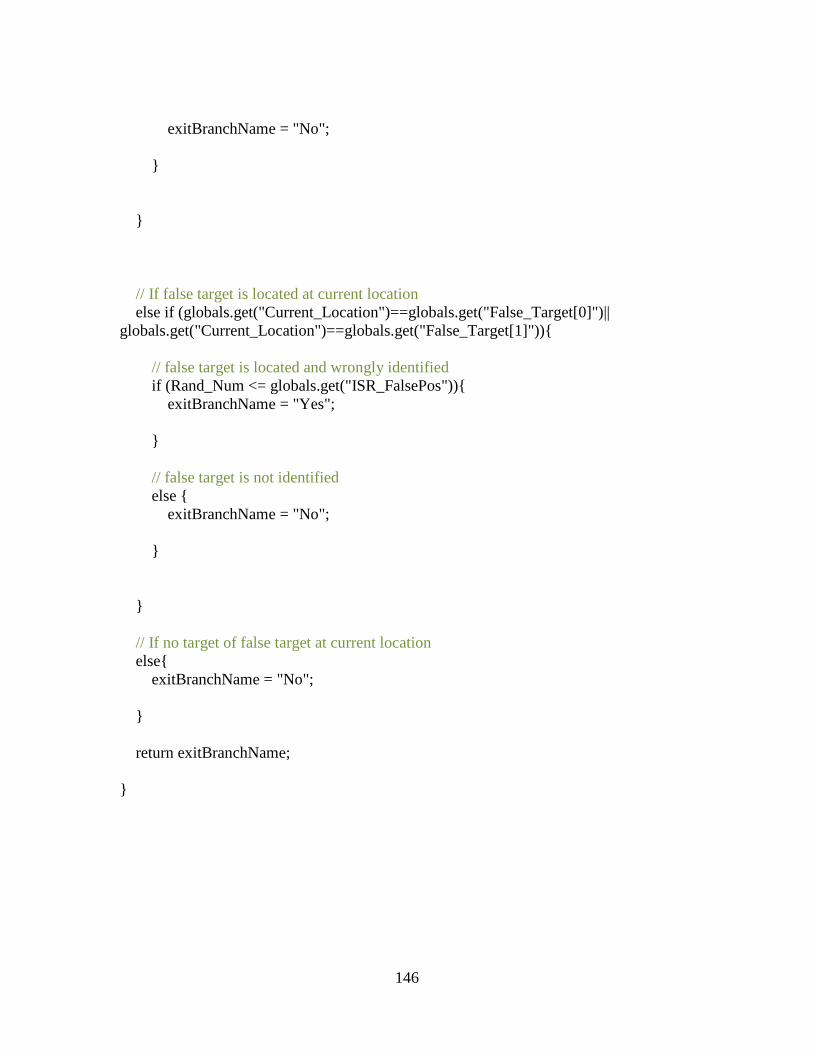
146
exitBranchName = "No"; } } // If false target is located at current location else if (globals.get("Current_Location")==globals.get("False_Target[0]")|| globals.get("Current_Location")==globals.get("False_Target[1]")){ // false target is located and wrongly identified if (Rand_Num <= globals.get("ISR_FalsePos")){ exitBranchName = "Yes"; } // false target is not identified else { exitBranchName = "No"; } } // If no target of false target at current location else{ exitBranchName = "No"; } return exitBranchName; }
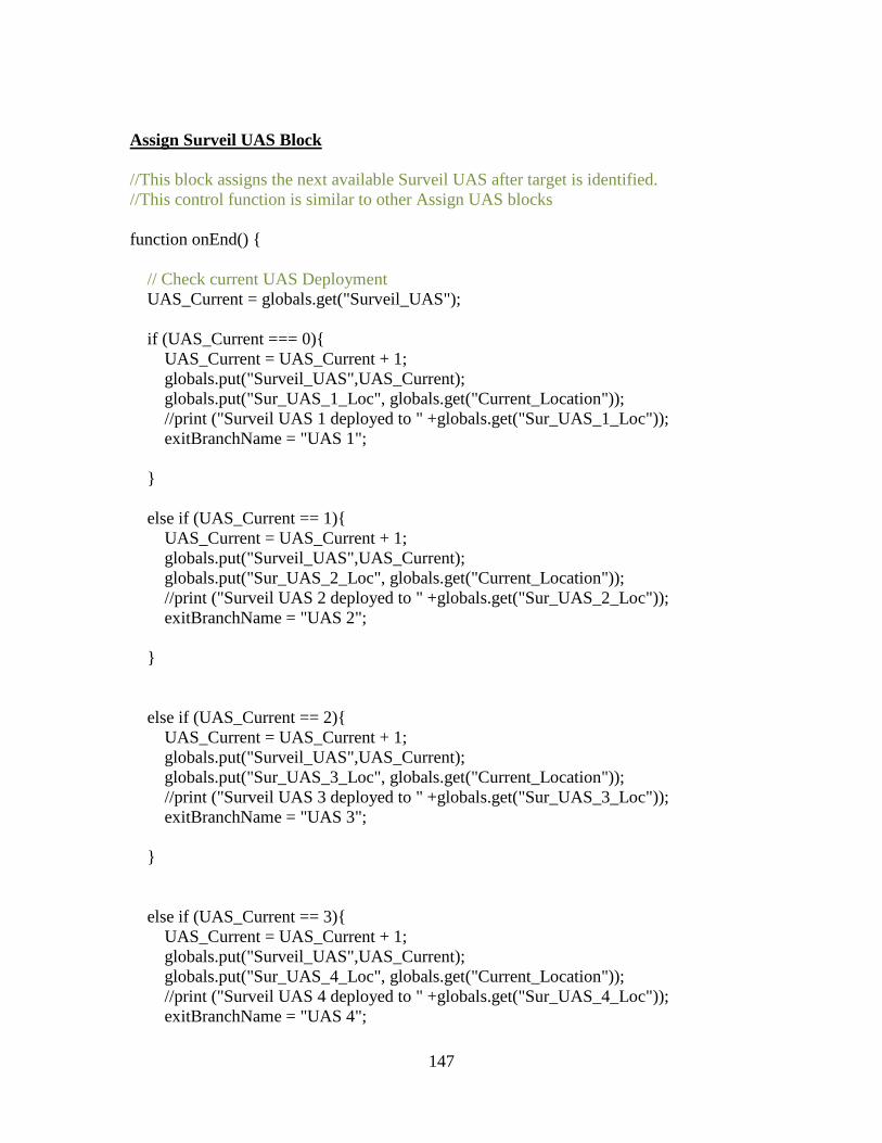
147
Assign Surveil UAS Block //This block assigns the next available Surveil UAS after target is identified. //This control function is similar to other Assign UAS blocks function onEnd() { // Check current UAS Deployment UAS_Current = globals.get("Surveil_UAS"); if (UAS_Current === 0){ UAS_Current = UAS_Current + 1; globals.put("Surveil_UAS",UAS_Current); globals.put("Sur_UAS_1_Loc", globals.get("Current_Location")); //print ("Surveil UAS 1 deployed to " +globals.get("Sur_UAS_1_Loc")); exitBranchName = "UAS 1"; } else if (UAS_Current == 1){ UAS_Current = UAS_Current + 1; globals.put("Surveil_UAS",UAS_Current); globals.put("Sur_UAS_2_Loc", globals.get("Current_Location")); //print ("Surveil UAS 2 deployed to " +globals.get("Sur_UAS_2_Loc")); exitBranchName = "UAS 2"; } else if (UAS_Current == 2){ UAS_Current = UAS_Current + 1; globals.put("Surveil_UAS",UAS_Current); globals.put("Sur_UAS_3_Loc", globals.get("Current_Location")); //print ("Surveil UAS 3 deployed to " +globals.get("Sur_UAS_3_Loc")); exitBranchName = "UAS 3"; } else if (UAS_Current == 3){ UAS_Current = UAS_Current + 1; globals.put("Surveil_UAS",UAS_Current); globals.put("Sur_UAS_4_Loc", globals.get("Current_Location")); //print ("Surveil UAS 4 deployed to " +globals.get("Sur_UAS_4_Loc")); exitBranchName = "UAS 4";

148
} return exitBranchName; }
149
Bibliography
Arena, M. V. (2006). Why has the cost of Navy ships risen?: A macroscopic examination of the trends in US Naval ship costs over the past several decades (Vol. 484). Rand Corporation.
Balmelli, L. (2007). An overview of the systems modeling language for products and systems development -- Part 3: Modeling system behavior. Journal of Object Technology, 6(6), 149–177.
Berteau, D. J., Ben-Ari, G., Hofbauer, J., & Sanders, G. (2010). Cost and Time Overruns for Major Defense Acquisition Programs: An Annotated Brief. Center for Strategic and International Studies, 1–17.
Biemans, F. P. M., Lankhorst, M. M., Teeuw, W. B., & van de Wetering, R. G. (2001). Dealing with the complexity of business systems architecting. Systems Engineering. http://doi.org/10.1002/sys.1010.
Bueno, A., Carreño, L. T., Delgado, D. J., & Llamosa-Villalba, R. (2014). Executable Architecture based on System Dynamics: An Integrated Methodology Composed by Standard System Dynamics Modelling and DoDAF Operational View Models. Procedia Computer Science, 36. http://doi.org/10.1016/j.procs.2014.09.042
Buurman, J., Zhang, S., & Babovic, V. (2009). Reducing risk through real options in systems design: The case of architecting a maritime domain protection system. Risk Analysis. http://doi.org/10.1111/j.1539-6924.2008.01160.x
Colombi, J. M., Miller, M. E., Bohren, J. S., & Howard, J. K. (2015). for a Manned Mission to Mars, 9(2), 495–507.
Crawley, E., Weck de, O., Eppinger, S., Magee, C., Moses, J., Seering, W., … Weck, O. De. (2004). The Influence of Architecture in Engineering Systems. Engineering Systems Monograph, 30.
Diaz-Rodriguez, L. M. (2005). Executable Model Development from Architectural Description with Application to the Time Sensitive Target Problem (No. AFIT/GSE/ENY/05-M04). AIR FORCE INST OF TECH WRIGHT-PATTERSONAFB OH DEPT OF AERONAUTICS AND ASTRONAUTICS.
Department of Defense. DoD Architecture Framework ver 2.0 Volume 1: Introduction, Overview, and Concepts (2009).
Department of Defense. DoD Architecture Framework ver 2.0 Volume 2: Architectural Data and Models (2009).
150
Department of Defense. DoD Architecture Framework ver 2.0 Volume 3: DoDAF Meta-model (2009).
Ciccozzi, F., Cicchetti, A., Siljamäki, T., & Kavadiya, J. (2010, September). Automating test cases generation: From xtUML system models to QML test models. In Proceedings of the 7th International Workshop on Model-Based Methodologies for Pervasive and Embedded Software (pp. 9-16). ACM.
Habayeb, R. (2005). Architecture-Based Systems Engineering and Integration. Engineering Conference.
Hu, J., Huang, L., Cao, B., & Chang, X. (2014). SPDML: Graphical modeling language for executable architecture of systems. Proceedings - 2014 International Conference on Cyber-Enabled Distributed Computing and Knowledge Discovery, CyberC 2014, 248–255. http://doi.org/10.1109/CyberC.2014.52
Innoslate (2012). Innoslate web-based software. Retrieved from http://www.innoslate.com/
Larman, Craig. (2004). Applying UML and Patterns: An Introduction to Object- Oriented Analysis and Design and the Unified Process. Vol. 17. N.p., 2004.
Lifecycle Modeling Language (LML) Specification. Dec 2015.
Liles, S. W. (2008). On the Characterization and Analysis of System of Systems Architectures. Transformation, 192.
Maier, M. W., & Ph, D. (1996). Developments in System Architecting, 139–142.
Mastro, P. C., Orcutt, C. R. L., Jacques, D. R., & Colombi, J. M. (2009). Enterprise Architecture Support for Capability Based Assessments. In 7th Annual Conference on Systems Engineering Research 2009 (CSER 2009).
Michael J. Sullivan. (2011) DOD Cost Overruns Trends in Nunn-McCurdy Breaches and Tools to Manage Weapon Systems. http://www.gao.gov/assets/130/125861.pdf on 27 Feb 2016
Microsoft. (2016). Create a box and whisker chart. Retrieved from https://support.office.com/en-us/article/Create-a-box-and-whisker-chart-62f4219f-db4b-4754-aca8-4743f6190f0d on 8 Jul 2016
Object Management Group (OMG). (2015). OMG Meta Object Facility Core Specification Version 2.5 Jun 2015.

151
Object Management Group (OMG). (2014). OMG Model Driven Architecture: MDA Guide rev 2.0. Jun 2014.
Object Management Group (OMG). (2015). OMG Unified Modeling Language Version 2.5. 2015.
Object Management Group(OMG). (2014) Model Driven Architecture: The Architecture of Choice for a Changing World. (2014): Retrieved from http://www.omg.org/mda/executive_overview.htm on 27 Feb 2016
Pospisal, Ryan M. (2015) Application of Executable Architectures in Early Concept Evaluation. AFIT-ENV-MS-15-D-027. Dec 2015
Rechtin, E. (1992). The art of systems architecting. IEEE Spectrum, 29(10), 66–69. http://doi.org/10.1109/6.158642
Rudat, A., Battat, J., & Cameron, B. (2013). The modeling and evaluation of interplanetary manned missions using system architecting techniques. IEEE Aerospace Conference Proceedings, 1–17. http://doi.org/10.1109/AERO.2013.6496944
Starr, L., & Stephen, J. (2001). Executable UML: how to build class models. Prentice Hall PTR.
Sparx Systems. (2016) MDA Style Transform. Retrieved from http://www.sparxsystems.com/resources/mda/ on 27 Feb 2016
T. Siljamaki and S. Andersson, “Performance benchmarking of real time critical function using BridgePoint xtUML,” NW-MoDE’08:Nordic Workshop on Model Driven Engineering. Reykjavik, Iceland, August 2008 (2008).
Tom Captain. (2009) Can We Afford Our Own Future ? Why A & D Programs Are Late. Retrieved from https://www2.deloitte.com/content/dam/Deloitte/us/Documents/manufacturing/us-ad-canweaffordourownfuture-0127.pdf on 27 Feb 2016.
US Government Accountability Office. “National Defense System Acquisitions.” (2016). Retrieved from http://www.gao.gov/key_issues/national_defense_space_system_acquisitions/issue_summary on 27 Feb 2016.
Wagenhals, L. W., Liles, S. W., & Levis, A. H. (2009). Toward executable architectures to support evaluation. 2009 International Symposium on Collaborative Technologies and Systems, CTS 2009, 502–511. http://doi.org/10.1109/CTS.2009.5067520

152
Wang, Z. He, H. and Wang, Q. (2014), Executable Architecture Modeling and Simulation Based on fUML. 9th International Command and Control Research and Technology Symposium pp 1-17.
Wang, R. & Dagli, C. H. (2011), Executable system architecting using systems modeling language in conjunction with colored Petri nets in a model-driven systems development process. Syst. Engin., 14: 383–409
Wang, R., & Dagli, C. H. (2008). An executable system architecture approach to discrete events system modeling using SysML in conjunction with Colored Petri Net. 2008 IEEE International Systems Conference Proceedings, SysCon 2008, 118–125. http://doi.org/10.1109/SYSTEMS.2008.4518997.
Wang, R., Agarwal, S., & Dagli, C. H. (2015). OPM & color petri nets based executable system of systems architecting: A building block in FILA-SoS. 9th Annual IEEE International Systems Conference, SysCon 2015 - Proceedings, 554–561. http://doi.org/10.1109/SYSCON.2015.7116810.
Younossi, O., Arena, M. V, Leonard, R. S., Charles Robert Roll, J., Jain, A., & Sollinger, J. M. (2007). Is Weapon System Cost Growth Increasing? A Quantitative Assessment of Completed and Ongoing Programs. Retrieved from http://www.rand.org/pubs/monographs/MG588.html.
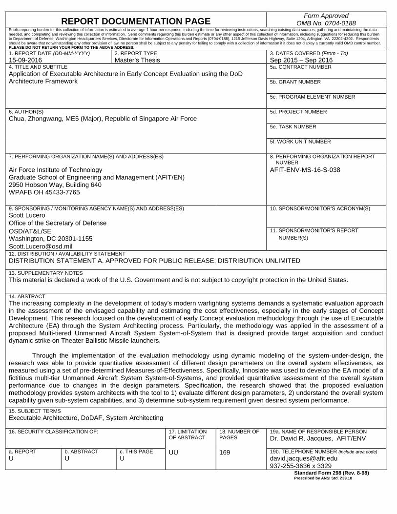
REPORT DOCUMENTATION PAGE Form Approved
OMB No. 0704-0188 Public reporting burden for this collection of information is estimated to average 1 hour per response, including the time for reviewing instructions, searching existing data sources, gathering and maintaining the data needed, and completing and reviewing this collection of information. Send comments regarding this burden estimate or any other aspect of this collection of information, including suggestions for reducing this burden to Department of Defense, Washington Headquarters Services, Directorate for Information Operations and Reports (0704-0188), 1215 Jefferson Davis Highway, Suite 1204, Arlington, VA 22202-4302. Respondents should be aware that notwithstanding any other provision of law, no person shall be subject to any penalty for failing to comply with a collection of information if it does not display a currently valid OMB control number. PLEASE DO NOT RETURN YOUR FORM TO THE ABOVE ADDRESS. 1. REPORT DATE (DD-MM-YYYY) 15-09-2016
2. REPORT TYPE Master’s Thesis
3. DATES COVERED (From - To) Sep 2015 – Sep 2016
4. TITLE AND SUBTITLE Application of Executable Architecture in Early Concept Evaluation using the DoD Architecture Framework
5a. CONTRACT NUMBER 5b. GRANT NUMBER
5c. PROGRAM ELEMENT NUMBER
6. AUTHOR(S) Chua, Zhongwang, ME5 (Major), Republic of Singapore Air Force
5d. PROJECT NUMBER
5e. TASK NUMBER
5f. WORK UNIT NUMBER 7. PERFORMING ORGANIZATION NAME(S) AND ADDRESS(ES)
8. PERFORMING ORGANIZATION REPORT NUMBER
Air Force Institute of Technology Graduate School of Engineering and Management (AFIT/EN) 2950 Hobson Way, Building 640 WPAFB OH 45433-7765
AFIT-ENV-MS-16-S-038
9. SPONSORING / MONITORING AGENCY NAME(S) AND ADDRESS(ES) 10. SPONSOR/MONITOR’S ACRONYM(S) Scott Lucero
Office of the Secretary of Defense
OSD/AT&L/SE
11. SPONSOR/MONITOR’S REPORT Washington, DC 20301-1155 NUMBER(S)
[email protected] 12. DISTRIBUTION / AVAILABILITY STATEMENT DISTRIBUTION STATEMENT A. APPROVED FOR PUBLIC RELEASE; DISTRIBUTION UNLIMITED
13. SUPPLEMENTARY NOTES This material is declared a work of the U.S. Government and is not subject to copyright protection in the United States.
14. ABSTRACT The increasing complexity in the development of today’s modern warfighting systems demands a systematic evaluation approach in the assessment of the envisaged capability and estimating the cost effectiveness, especially in the early stages of Concept Development. This research focused on the development of early Concept evaluation methodology through the use of Executable Architecture (EA) through the System Architecting process. Particularly, the methodology was applied in the assessment of a proposed Multi-tiered Unmanned Aircraft System System-of-System that is designed provide target acquisition and conduct dynamic strike on Theater Ballistic Missile launchers.
Through the implementation of the evaluation methodology using dynamic modeling of the system-under-design, the research was able to provide quantitative assessment of different design parameters on the overall system effectiveness, as measured using a set of pre-determined Measures-of-Effectiveness. Specifically, Innoslate was used to develop the EA model of a fictitious multi-tier Unmanned Aircraft System System-of-Systems, and provided quantitative assessment of the overall system performance due to changes in the design parameters. Specification, the research showed that the proposed evaluation methodology provides system architects with the tool to 1) evaluate different design parameters, 2) understand the overall system capability given sub-system capabilities, and 3) determine sub-system requirement given desired system performance. 15. SUBJECT TERMS Executable Architecture, DoDAF, System Architecting
16. SECURITY CLASSIFICATION OF:
17. LIMITATION OF ABSTRACT
18. NUMBER OF PAGES
19a. NAME OF RESPONSIBLE PERSON Dr. David R. Jacques, AFIT/ENV
a. REPORT U
b. ABSTRACT U
c. THIS PAGE U
UU 169
19b. TELEPHONE NUMBER (include area code) [email protected] 937-255-3636 x 3329 Standard Form 298 (Rev. 8-98)
Prescribed by ANSI Std. Z39.18
Recommended