19/1Siemens Industry, Inc.Industrial Controls Catalog
AppendixGeneral Information
Siemens / Industrial Controls Previous folio: 19/1
Contents Pages
UL and CSA file and guide numbers . . . . . . . . . . . . . . . .19/2
On-line References for Industrial Control Products . . . . .19/3
General InformationNEMA enclosure descriptions . . . . . . . . . . . . . . . . . . .19/4IEC enclosure descriptions . . . . . . . . . . . . . . . . . . . . .19/5IEC contactor utilization categories . . . . . . . . . . . . . . . .19/6Control circuit classifications . . . . . . . . . . . . . . . . . . . .19/7Ampere ratings for 3 phase AC induction motors . . . .19/8Metric to US conversions . . . . . . . . . . . . . . . . . . . . . .19/9Electical formulas and grounding requirements . . . .19/10NEMA and IEC terminal markings . . . . . . . . . . . . . . .19/11Electrical symbols . . . . . . . . . . . . . . . . . . . . . . . . . . .19/12Control circuit schematics . . . . . . . . . . . . . . . . . . . . .19/13Control circuit schematics and wiring diagrams . . . . .19/14Pilot control . . . . . . . . . . . . . . . . . . . . . . . . . . . . . . . .19/15
International Control EquipmentQuick reference list . . . . . . . . . . . . . . . . . . . . . . . . . . .19/16
Spring Loaded Terminal Technique . . . . . . . . . . . . . . . .19/17
Standard Terms & Conditions of Sale . . . . . . . . . . . . . .19/18
10IC19_01-18.qxd 7/30/09 2:18 PM Page 19/1

SiemIndus
19/2 Siemens Industry, Inc.Industrial Controls Catalog
UL and CSA file numbers and guide card numbers
AppendixStandards and Approvals
Siemens / Industrial Controls Previous folio: new page
Most control equipment listed in this catalog is designed, manufactured and tested in accordance with the relevant UL and CSA standards as listed on pages 19/2 and 19/3.
Equipment Sec detsil-LUASC UL-recognized
s u cu U cU
Guide No. File No. Guide No. File No. Guide No. File No.
3RV1 motor starter protectors 1 Class 3211 08 LR 12730 NLRV NLRV7 E 47705 NLRV2 – E 47705
3RV1 as self-protected controller (Type E) 1 Class 3211 08 LR 12730 NKJH NKJH7 E 156943 – – –
3RV17 and 18 as circuit breakers 1 Class 1432 01 LR 12730 DIVQ DIVQ7 E 235044 – – –
3RT contactors 2 Class 3211 04 LR 12730 NLDX NLDX7 E 31519 NLDX2 – E 31519
3TB contactors 2 Class 3211 04 LR 12730 NLDX NLDX7 E 31519 NLDX2 – E 31519
3TC DC contactors 2 – – – – – NLDX2 – E 79773
3TF6 contactors 2 Class 3211 04 LR 12730 NLDX NLDX7 E 31519 NLDX2 – E 31519
3RA13 reversing contactors 2 Class 3211 04 LR 12730 NLDX – E 31519 NLDX2 – E 31519
3TX7 surge suppressors 2 Class 3211 03 LR 12730 – – – NKCR2 NKCR8 E 31519
3RH control relays 2 Class 3211 03 LR 12730 NKCR NKCR7 E 44653 NKCR2 – E 44653
3RU11 thermal overload relay 3 Class 3211 03 LR 12730 NKCR NKCR7 E 44653 – – –
3RB20/21 solid-state overload relay 3 Class 3211 03 LR 12730 NKCR NKCR7 E 44653 – – –
3RB22/23 solid-state overload relay 3 Class 3211 03 LR 12730 NKCR NKCR7 E 44653 – – –
3RB293 solid-state overload relay 3 Class 3211 03 LR 12730 NKCR NKCR7 E 44653 – – –
3UF7 SIMOCODE intelligent overload relay 3 Class 3211 03 LR 12730 NKCR NKCR7 E 44653 – – –
3RA11/12 combination starters 4 Class 3211 05 LR 12730 NLDX – E 31519 – – –
3RA6 compact starter as manual motor controller
4 Class 3211 05 LR 12730 NLRV NLRV7 E 47705 – – –
3RA6 compact starter as self-protected controller (Type E)
4 Class 3211 08 LR 12730 NKJH NKJH7 E 156943 – – –
8US1 busbar adapter system 5 2) 2) – – – NMTR2 NMTR8 E 148698
FB busbar adapter system 5 2) 2) – – – NMTR2 NMTR8 E 160776
3RW30 soft starters (NEW) 6 Class 3211 06 LR 12730 NMFT NMFT7 E 143112 – – –
3RW30/31 soft starters 6 Class 3211 06 LR 12730 NMFT NMFT7 E 143112 – – –
3RW40/44 soft starters 6 Class 3211 06 – – – E 68456 – – –
73 enclosed soft starters 6 – – – – E 43399 – – –
74 combination soft starters 6 – – – – E 43399 – – –
3RF2 solid-state relays and contactors 7 Class 3211 07 LR 12730 NMFT NMFT7 E 143112 – – –
11, 12 manual switches 8 Class 3211 LR 6535 NLVR – E 10590 NLRV2 – E 10590
14, 22, 30, 40, 43 starters and contactors 8 Class 3211 LR 6535 NLDX – E 14900 NLDX2 – E 14900
17, 18, 25, 26, 32 combination starters 8 Class 3211 LR 6535 NKJH – E 185287 – – –
36, 37 reduced voltage starters 8 Class 3211 LR 6535 NLDX – E 14900 NLDX2 – E 14900
83, 84, 85, 87, 88 pump control panels 8 Class 3211 LR 6535 NKJH – E 185287 – – –
48, 958 overload relays ESP100 8 Class 3211 LR 6535 NKCR – E 22655 NKCR2 – E 22655
48, 958 overload relays ESP200 (NEW) 8 Class 3211 03 LR 12730 NKCR NKCR7 E 44653 – – –
49 field kits 8 Class 3211 ELR 535 NLDX – E 14900 NLDX2 – E 14900
16, 41, 42, 45 definite purpose controls 9 Class 3211 LR 6535 – – – NLDX2 – E 14900
3SB2 16 mm pushbuttons and indicator lights
10 Class 3211 03 LR 12730 – – – NKCR2 – E 44653
3SB3 22 mm pushbuttons and indicator lights
10 Class 3211 03 LR 12730 NKCR NKCR7 E 44653 NKCR2 – E 44653
50 standard duty pilot devices 10 Class 3211 LR 6535 NKCR – E 22655 – – –
51 hazardous location pilot devices 10 Class 3218 LR 23889 NOIV – E 39935 – – –
52 30 mm pilot devices 10 Class 3211 LR6535 NKCR – E 22655 NKCR2 – E 22655
3RS10/11 temperature monitoring relay 11 – – NKCR – E 44653 – – –
3RN1 termistor motor protection 11 Class 3211 03 LR 12730 NKCR NKCR7 E 44653 – – –
3RP1 electronic time-delay relay 11 Class 3211 03 LR 12730 NKCR NKCR7 E 44653 – – –
7PV time-delay relay 11 Class 2211 03 LR 12730 – – – NRNT2 NRNT8 E 44653
3UG monitoring relay 11 1) 1) NRNT NRNT7 E 44653 – – –
3TX70 coupling devices 11 Class 2211 03 LR 12730 NKLR – E 44653 NKCR2 – E 44653
3TX71 plug-in relays 11 – – – – – – – E 14900
3TX71 sockets 11 – – – – – – – E 196786
3TG10 power relay 11 1) 1) NLDX NLDX7 E 31519 – – –
3RS17 interface converter 11 1) 1) NKCR NKCR7 E 44653 – – –
1) cu listing for Canada, instead of CSA certification.2) cU recognition for Canada, instead of CSA certification.
10IC19_01-18.qxd 7/30/09 2:18 PM Page 19/2
19/3Siemens Industry, Inc.Industrial Controls Catalog
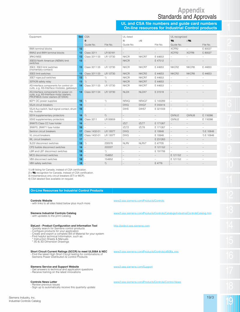
UL and CSA file numbers and guide card numbersOn-line resources for Industrial Control products
AppendixStandards and Approvals
Siemens / Industrial Controls Previous folio: new page
Inc.talog
Equipment Sec detsil-LUASC UL-recognized
s u cu U cU
Guide No. File No. Guide No. File No. Guide No. File No.
8WA terminal blocks 12 – – – – – XCFR2 – E 80027
8WA2 and 8WH terminal blocks 12 Class 3211 LR 50181 – – – XCFR2 XCFR8 E 80027
3RK3 MSS 13 Class 3211 03 LR 12730 NKCR NKCR7 E 44653 – – –
3SE03 North American (NEMA) limit switches
13 – – NKCR – E 47512 – – –
3SE2, 3SE3 limit switches (momentary-contact)
13 Class 3211 03 LR 12730 NKCR NKCR7 E 44653 NKCR2 NKCR8 E 44653
3SE5 limit switches 13 Class 3211 03 LR 12730 NKCR NKCR2 E 44653 NKCR2 NKCR8 E 44653
3SE7 rope pull switches 13 1) 1) NKCR NKCR7 E 44653 – – –
33TK28 safety relay 13 1) 1) NKCR NKCR7 E 44653 – – –
AS-Interface components for control cir-cuits, e.g. AS-Interface modules, gateways
14 Class 3211 03 LR 12730 NKCR NKCR7 E 44653 – – –
AS-Interface components for power cir-cuits, e.g. AS-Interface motor starters, PROFIBUS motor starters (ET200X)
14 Class 3211 04 LR 12730 NLDX NLDX7 E 31519 – – –
6EP1 DC power supplies 15 1) 1) NRAQ NRAQ7 E 143289 – – –
5SJ4 circuit breakers 16 – – DIVQ DIVQ7 E 243414 – – –
5SJ4 Aux switch, fault signal contact, shunt trip, busbar
16 – – DIHS DIHS7 E 321559 – – –
5SY4 supplementary protectors 16 2) 2) – – – QVNU2 QVNU8 E 116386
5SX2 supplementary protectors 16 Class 3211 LR 93659 – – – QVNU2 – E 116386
3NW75 Class CC fuse holder 16 – – IZLT IZLT7 E 171267 – – –
3NW70, 3NW71 fuse holder 16 – – IZLT2 IZLT8 E 171267 – – –
Sentron circuit breakers 17 Class 1432-01 LR 13077 DIVQ – E 10848 – – 3) E 10848
VL circuit breakers 17 Class 1432-01 LR 13077 DIVQ – E 10848 – – 3) E 10848
WL circuit breakers 17 – – – – E 231263 – – –
3LD2 disconnect switches 18 1) 230576 NLRV NLRV7 E 47705 – – –
CFS fusible disconnect switches 18 – 222227 – – E 121152 – – –
LBR and LBT disconnect switches 18 – 1) – – E 191706 – – –
MCS disconnect switches 18 – 154852 – – – E 121152 – –
VBII disconnect switches 18 – 154852 – – – E 121152 – –
VBII safety switches 18 – 4) – – E 4776 – – –
On-Line Resources for Industrial Control Products
Controls Website- with links to all sites listed below plus much more
www2.sea.siemens.com/Products/Controls
Siemens Industrial Controls Catalog- with updates to the print Catalog
www2.sea.siemens.com/Products/Controls/Catalogs/IndustrialControlsCatalog.htm
SieLect - Product Configuration and Information Tool- Quickly search for Siemens control products - Configure products for your application - Create and export a complete Bill of Material for your system - Find helpful technical Information, such as: * Instruction Sheets & Manuals * 2D & 3D Dimension Drawings
http://sielect.sea.siemens.com
Short Circuit Current Ratings (SCCR) to meet UL508A & NEC- Find the latest High Short Circuit testing for combinations of
Siemens Power Distribution & Control Products
www2.sea.siemens.com/Products/Controls/ul508a_nec
Siemens Service and Support Website- Get answers to technical and application questions- Receive training on the latest innovations
www2.sea.siemens.com/Support
Controls News Letter - Review previous issues- Sign up to automatically receive this quarterly update
www2.sea.siemens.com/Products/Controls/Control-News
1) cu listing for Canada, instead of CSA certification.2) cU recognition for Canada, instead of CSA certification.3) Instantaneous only circuit breakers (ETI or MCP).4) CSA labeled Sws available on request.
10IC19_01-18.qxd 8/26/09 2:52 PM Page 19/3

19/4 Siemens Industry, Inc.Industrial Controls Catalog
SiemIndus
NEMA enclosure descriptions
AppendixGeneral Information
Siemens / Industrial Controls Previous folio: 19/15
NEMA Standard Publications
No. 250-1979
Type 1
Type 1 enclosures are intended forindoor use primarily to provide adegree of protection against con-tact with the enclosed equipmentin locations where unusual serviceconditions do not exist. The enclo-sures shall meet the rod entry andrust resistance design tests.
Type 3
Type 3 enclosures are intendedfor outdoor use, primarily to pro-vide a degree of protectionagainst windblown dust, rain andsleet, and to be undamaged bythe formation of ice on the enclo-sure. They shall meet rain, exter-nal icing, dust, and rust resis-tance design tests. They are notintended to provide protectionagainst conditions such as inter-nal condensation or internalicing.
Type 3R
Type 3R enclosures are intendedfor outdoor use, primarily to pro-vide a degree of protectionagainst falling rain, and to beundamaged by the formation ofice on the enclosure. They shallmeet rod entry, rain, externalicing, and rust resistance designtests. They are not intended toprovide protection against condi-tions such as dust, internal con-densation, or internal icing.
Type 4
Type 4 enclosures are intended forindoor or outdoor use, primarily toprovide a degree of protectionagainst windblown dust and rain,splashing water, and hose directedwater, and to be undamaged bythe formation of ice on the enclo-sure. They shall meet hosedown,external icing, and rust resistancedesign tests. They are not intendedto provide protection against con-ditions such as internal condensa-tion or internal icing.
Type 4X
Type 4X enclosures are intendedfor indoor or outdoor use, primarilyto provide a degree of protectionagainst corrosion, windblown dustand rain, splashing water, andhose-directed water, and to beundamaged by the formation of iceon the enclosure. They shall meethosedown, external icing, and cor-rosion resistance design tests. Theyare not intended to provide protec-tion against conditions such asinternal condensation or internalicing.
Shall be manufactured ofAmerican Iron and Steel InstituteType 304 Stainless steel, poly-merics, or materials with equiva-lent corrosion resistance to pro-vide a degree of protectionagainst specific corrosive agents.
Type 6
Type 6 enclosures are intendedfor indoor or outdoor use, primar-ily to provide a degree of protec-tion against the entry of waterduring occasional temporarysubmersion at a limited depth.
Type 6P enclosures are intendedfor indoor or outdoor use primari-ly to provide a degree of protec-tion against the entry of waterduring prolonged submersion ata limited depth.
Type 7
Type 7 enclosures are for indooruse in locations classified asClass l, Groups C or D, asdefined in the National ElectricalCode.
Type 7 enclosures shall be capa-ble of withstanding the pressuresresulting from an internal explosionof specified gases and containsuch an explosion sufficiently thatan explosive gas-air mixture exist-ing in the atmosphere surroundingthe enclosure will not be ignited.Enclosed heat generating devicesshall not cause external surfaces toreach temperatures capable of
igniting explosive gas-air mixturesin the surrounding atmosphere.Enclosures shall meet explosion,hydrostatic, and temperaturedesign tests.
Type 9
Type 9 enclosures are intendedfor indoor use in locations classi-fied as Class ll Groups E, F or G,as defined in the NationalElectrical Code.
Type 9 enclosures shall be capa-ble of preventing the entrance ofdust. Enclosed heat generatingdevices shall not cause externalsurfaces to reach temperaturescapable of igniting or discoloringdust on the enclosure or ignitingdust-air mixtures in the surround-ing atmosphere. Enclosures shallmeet dust penetration and tem-perature design tests, and agingof gaskets (if used).
Class l—Flammable gases orvapors.
Class ll—Combustible dust.
Class lll—Ignitable fibers or fly-ings.
Division l—Normal situation; thehazard would be expected to bepresent in everyday repair andmaintenance.
Division ll—Abnormal situation;the material is expected to beconfined within closed containersor closed systems and will bepresent only during accidentalrupture, breakage or unusualfaulty operation.
Groups
Class l—Gases and vapors aredesigned for use in groups Cand D, depending on the ignitiontemperature of the substance, itsexplosion pressure and otherflam-mable characteristics.
Class ll—Dust locations aredesigned for use in groups E, F,and G, according to the ignition
temperature and conductivity ofthe hazardous substance.
Type 12
Type 12 enclosures are intendedfor indoor use primarily to providea degree of protection againstdust, falling dirt, and drippingnon-corrosive liquids. They shallmeet drip, dust, and rust resis-tance design tests. They are notintended to provide protectionagainst conditions such as inter-nal condensation.
Siemens NEMA 12 may be fieldmodified for outdoor use. NEMA3 requires the use of watertightconduit hubs. NEMA 3R requiresthe use of watertight conduithubs at a level above the lowestlive part and drain holes of 1⁄8"diameter shall be added at thebottom of the enclosure.Type 13
Type 13 enclosures are intendedfor indoor use primarily to providea degree of protection againstdust, spraying of water, oil andnon-corrosive coolant. They shallmeet oil explosion and rust resis-tance design tests. They are notintended to provide protectionagainst conditions such as inter-nal condensation.
Type 1 Type 3/3R Type 4/4X Type 4X Type 3, 4, 7 & 9 Type 12 & 13
Pth
InRWFFCSHOOC
Co
Thvid
IE
Co
IEsythdetaseag
F
Pp
012
345
6
Thnaapvebe
N
10IC19_01-18.qxd 7/30/09 11:01 AM Page 19/4
19/5 Inc.talog
Siemens Industry, Inc.Industrial Controls Catalog
IEC enclosure descriptions
AppendixGeneral Information
Siemens / Industrial Controls Previous folio: 19/16
of
dedvidet
alls-notner-
ldMAhtres
est8"e
dedvidetdhallsis-notner-
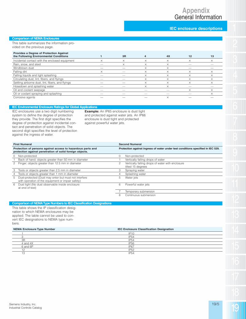
Provides a Degree of Protection Against the Following Environmental Conditions 1 3R 4 4X 12 13
Incidental contact with the enclosed equipment � � � � � �Rain, snow, and sleet — � � � — —Windblown dust — — � � — —Falling dirt � — � � � �Falling liquids and light splashing — — � � � �Circulating dust, lint, fibers, and flyings — — � � � �Settling airborne dust, lint, fibers, and flyings — — � � � �Hosedown and splashing water — — � � — —Oil and coolant seepage — — — — � �Oil or coolant spraying and splashing — — — — — �Corrosive agents — — — � — —
Comparison of NEMA Enclosures
This table summarizes the information pro-vided on the previous page.
IEC Environmental Enclosure Ratings for Global Applications
Comparison of NEMA Type Numbers to IEC Classification Designations
IEC enclosures use a two digit numberingsystem to define the degree of protectionthey provide. The first digit specifies thedegree of protection against incidental con-tact and penetration of solid objects. Thesecond digit specifies the level of protectionagainst the ingress of water.
Example: An IP65 enclosure is dust tightand protected against water jets. An IP66enclosure is dust tight and protectedagainst powerful water jets.
First Numeral Second Numeral
Protection of persons against access to hazardous parts and Protection against ingress of water under test conditions specified in IEC 529.protection against penetration of solid foreign objects.
0 Non-protected 0 Non-protected1 Back of hand; objects greater than 50 mm in diameter 1 Vertically falling drops of water2 Finger; objects greater than 12.5 mm in diameter 2 Vertically falling drops of water with enclosure
tilted 15 degrees3 Tools or objects greater than 2.5 mm in diameter 3 Spraying water4 Tools or objects greater than 1 mm in diameter 4 Splashing water5 Dust-protected (Dust may enter but must not interfere 5 Water jets
with operation of the equipment or impair safety)6 Dust tight (No dust observable inside enclosure 6 Powerful water jets
at end of test)7 Temporary submersion8 Continuous submersion
This table shows the IP classification desig-nation to which NEMA enclosures may beapplied. The table cannot be used to con-vert IEC designations to NEMA type num-bers.
NEMA Enclosure Type Number IEC Enclosure Classification Designation
1 IP103 IP543R IP544 and 4X IP566 and 6P IP6712 IP5213 IP54
10IC19_01-18.qxd 7/30/09 11:01 AM Page 19/5
19/6 Siemens Industry, Inc.Industrial Controls Catalog
SiemIndus
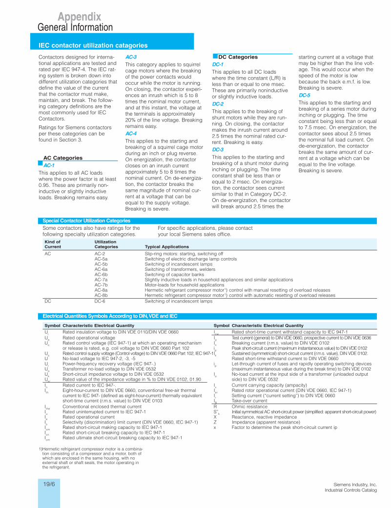
IEC contactor utilization catagories
AppendixGeneral Information
Siemens / Industrial Controls Previous folio: 19/17
Kind of UtilizationCurrent Categories Typical Applications
AC AC-2 Slip-ring motors: starting, switching offAC-5a Switching of electric discharge lamp controlsAC-5b Switching of incandescent lampsAC-6a Switching of transformers, weldersAC-6b Switching of capacitor banksAC-7a Slightly inductive loads in household appliances and similar applicationsAC-7b Motor-loads for household applicationsAC-8a Hermetic refrigerant compressor motor1) control with manual resetting of overload releasesAC-8b Hermetic refrigerant compressor motor1) control with automatic resetting of overload releases
DC DC-6 Switching of incandescent lamps
Special Contactor Utilization Categories
Some contactors also have ratings for thefollowing specialty utilization categories.
For specific applications, please contactyour local Siemens sales office.
Electrical Quantities Symbols According to DIN,VDE and IEC
Contactors designed for interna-tional applications are tested andrated per IEC 947-4. The IEC rat-ing system is broken down intodifferent utilization categories thatdefine the value of the currentthat the contactor must make,maintain, and break. The follow-ing category definitions are themost commonly used for IECContactors.
Ratings for Siemens contactorsper these categories can befound in Section 3.
AC Categories
AC-1
This applies to all AC loadswhere the power factor is at least0.95. These are primarily non-inductive or slightly inductiveloads. Breaking remains easy.
AC-3
This category applies to squirrelcage motors where the breakingof the power contacts wouldoccur while the motor is running.On closing, the contactor experi-ences an inrush which is 5 to 8times the nominal motor current,and at this instant, the voltage atthe terminals is approximately20% of the line voltage. Breakingremains easy.AC-4
This applies to the starting andbreaking of a squirrel cage motorduring an inch or plug reverse.On energization, the contactorcloses on an inrush currentapproximately 5 to 8 times thenominal current. On de-energiza-tion, the contactor breaks thesame magnitude of nominal cur-rent at a voltage that can beequal to the supply voltage.Breaking is severe.
DC Categories
DC-1
This applies to all DC loadswhere the time constant (L/R) isless than or equal to one msec.These are primarily noninductiveor slightly inductive loads.DC-2
This applies to the breaking ofshunt motors while they are run-ning. On closing, the contactormakes the inrush current around2.5 times the nominal rated cur-rent. Breaking is easy.DC-3
This applies to the starting andbreaking of a shunt motor duringinching or plugging. The timeconstant shall be less than orequal to 2 msec. On energiza-tion, the contactor sees currentsimilar to that in Category DC-2.On de-energization, the contactorwill break around 2.5 times the
starting current at a voltage thatmay be higher than the line volt-age. This would occur when thespeed of the motor is lowbecause the back e.m.f. is low.Breaking is severe.DC-5
This applies to the starting andbreaking of a series motor duringinching or plugging. The timeconstant being less than or equalto 7.5 msec. On energization, thecontactor sees about 2.5 timesthe nominal full load current. Onde-energization, the contactorbreaks the same amount of cur-rent at a voltage which can beequal to the line voltage.Breaking is severe.
1)Hermetic refrigerant compressor motor is a combina-tion consisting of a compressor and a motor, both ofwhich are enclosed in the same housing, with noexternal shaft or shaft seals, the motor operating inthe refrigerant.
Symbol Characteristic Electrical Quantity Symbol Characteristic Electrical Quantity
Ui Rated insulation voltage to DIN VDE 0110/DIN VDE 0660 Icw Rated short-time current withstand capacity to IEC 947-1Ue Rated operational voltage Ip Test current (general) to DIN VDE 0660, prospective current to DIN VDE 0636Uc Rated control voltage (IEC 947-1) at which an operating mechanism In Breaking current (r.m.s. value) to DIN VDE 0102
or release is rated, e.g. coil voltage to DIN VDE 0660 Part 102 ip Peak short-circuit current (maximum instantaneous value) to DIN VDE 0102Us Rated control supply voltage (Control voltage) to DIN VDE 0660 Part 102, IEC 947-1Ik Sustained (symmetrical) short-circuit current (r.m.s. value), DIN VDE 0102. U No-load voltage to IEC 947-2, -3, -5 Rated short-time withstand current to DIN VDE 0660Ur Power-frequency recovery voltage (IEC 947-.) ip Let-through current of fuses and rapidly operating switching devices Uo Transformer no-load voltage to DIN VDE 0532 (maximum instantaneous value during the break time) to DIN VDE 0102Uk Short-circuit impedance voltage to DIN VDE 0532 Io No-load current at the input side of a transformer (unloaded outputUkr Rated value of the impedance voltage in % to DIN VDE 0102, 01.90 side) to DIN VDE 0532In Rated current to IEC 947-. Ix Current carrying capacity (ampacity)Ith Eight-hour-current to DIN VDE 0660, conventional free-air thermal Isr Rated rotor operational current (DIN VDE 0660, IEC 947-1)
current to IEC 947- (defined as eight-hour-current) thermally equivalent Ir Setting current (“current setting”) to DIN VDE 0660short-time current (r.m.s. value) to DIN VDE 0103 IB Take-over current
Ithe Conventional enclosed thermal current R Ohmic resistanceIu Rated uninterrupted current to IEC 947-1 S”k Initial symmetrical AC short-circuit power (simplified: apparent short-circuit power)Ie Rated operational current X Reactance, reactive impedanceIs Selectivity (discrimination) limit current (DIN VDE 0660, IEC 947-1) Z Impedance (apparent resistance)Icm Rated short-circuit making capacity to IEC 947-1 x Factor to determine the peak short-circuit current ipIcn Rated short-circuit breaking capacity to IEC 947-1Icm Rated ultimate short-circuit breaking capacity to IEC 947-1
Ie
(C
1
AUC
p
AAAA
1)Theag150Tes
R
C
R
D
AAABBBCCCDDE
R
CR
D
NNNPPPQQQRR
AC
AC
NEco
DC
Co
IE15
Ex
10IC19_01-18.qxd 7/30/09 2:19 PM Page 19/6

19/7 Inc.talog
Siemens Industry, Inc.Industrial Controls Catalog
NEMA and IEC control circuit classifications
AppendixGeneral Information
Siemens / Industrial Controls Previous folio: 19/18
hatolt-he
w.
dring
qualthes
Onrur-e
36
es 02
ower)
Ie/AC-12 U
eIe/AC-15
(Continuous Amps) AC Voltage Amps
24V 6A
10 110V 6A220/230V 6A380/440V 4A
Voltage Ie/DC-12 I
e/DC-13
24 6A 3A60 5A 1.5A110 2.5A 0.7A230 1A 0.3A
AC Control CircuitUtilizationCategories Make Break
per IEC 947-5-1 I/Ie
U/Ue
I/Ie
U/Ue
AC-12 1 1 1 1AC-13 2 1 1 1AC-14 6 1 1 1AC-15 10 1 1 1
DC Control CircuitUtilizationCategories Make Break
per IEC 947-5-1 I/Ie
U/Ue
I/Ie
U/Ue
DC-12 1 1 1 1DC-13 1 1 1 1DC-14 10 1 1 1
1)The numerical suffix designates the maximum volt-age design values, which are to be 600, 300, and150 volts for suffixes 600, 300, and 150 respectively.Test voltage shall be 600, 250, or 125 volts. MLLDLL.
2)For maximum ratings at 300 volts or less, the maxi-mum make and break ratings are to be obtained bydividing the volt-ampere rating by the applicationvoltage, but the current value is not to exceed thethermal continuous test current.
3) Ie Rated operational currentUe Rated operational voltageI Current to be made or brokenU Voltage before make
4)Example: A control circuit contact having an AC-15rating of 6 amps at 230 volts is capable of making 60amps and breaking 6 amps at 230 volts. KRE.
Ratings & Test Values for AC Control Circuit Contacts at 50 or 60Hz
ThermalContact Continuous
Maximum Current, Amperes
Rating Test Current,120 Volts 240 Volts 480 Volts 600 Volts Voltamperes
Designation Amperes Make Break Make Break Make Break Make Break Make Break
A150 10 60 6 — — — — — — 7200 720A300 10 60 6 30 3 — — — — 7200 720A600 10 60 6 30 3 15 1.5 12 1.2 7200 720B150 5 30 3 — — — — — — 3600 360B300 5 30 3 15 1.5 — — — — 3600 360B600 5 30 3 15 1.5 7.5 0.75 6 0.6 3600 360C150 2.5 15 1.5 — — — — — — 1800 180C300 2.5 15 1.5 7.5 0.75 — — — — 1800 180C600 2.5 15 1.5 7.5 0.75 3.75 0.375 3 0.3 1800 180D150 1 3.6 0.6 — — — — — — 432 72D300 1 3.6 0.6 1.8 0.3 — — — — 432 72E150 0.5 1.8 0.3 — — — — — — 216 36
Rating codes for DC Control Circuit Contacts
Thermal MaximumContact Continuous Maximum Make or Break2) Make or BreakRating Test Current, Current, Amperes Voltamperes
Designation1) Amperes 125 Volt 250 Volt 301 to 600 Volt at 300 Volts or Less
N150 10 2.2 — — 275N300 10 2.2 1.1 — 275N600 10 2.2 1.1 0.4 275P150 5 1.1 — — 138P300 5 1.1 0.55 — 138P600 5 1.1 0.55 0.2 138Q150 2.5 0.55 — — 69Q300 2.5 0.55 0.27 — 69Q600 2.5 0.55 0.27 0.1 69R150 1 0.22 — — 28R300 1 0.22 0.11 — 28
AC DC
AC-Control Circuit Classifications—NEMA
NEMA designates Control Circuit Rating with acode letter (for current) and a voltage code.
DC-Control Circuit Classifications—NEMA
Control Circuit Classifications—IEC3)IEC 947-5-1 Uses Utilization Categories AC-15 to Specify Control Circuit Ranges.
Current at each voltage is specified by themanufacturer, not by the standard.
Example of a Typical IEC Control Circuit Ratings Table4)
10IC19_01-18.qxd 7/30/09 2:19 PM Page 19/7

19/8 Siemens Industry, Inc.Industrial Controls Catalog
SiemIndus
Ampere ratings for 3 phaseAC induction motors
AppendixGeneral Information
Siemens / Industrial Controls Previous folio: 19/19
Amperes 60Hz
SynSpeed 200 230 460 575
Hp RPM Volts Volts Volts Volts
3600 69.9 60.8 30.4 24.325 1800 74.5 64.8 32.4 25.9
1200 75.4 65.6 32.8 26.2900 77.4 67.3 33.7 27.0
3600 84.8 73.7 36.8 29.430 1800 86.9 75.6 37.8 30.2
1200 90.6 78.8 39.4 31.5900 94.1 81.8 40.9 32.7
3600 111 96.4 48.2 38.540 1800 116 101 50.4 40.3
1200 117 102 50.6 40.4900 121 105 52.2 41.7
3600 138 120 60.1 48.250 1800 143 124 62.2 49.7
1200 145 126 63.0 50.4900 150 130 65.0 52.0
3600 164 143 71.7 57.360 1800 171 149 74.5 59.4
1200 173 150 75.0 60.0900 177 154 77.0 61.5
3600 206 179 89.6 71.775 1800 210 183 91.6 73.2
1200 212 184 92.0 73.5900 222 193 96.5 77.5
3600 266 231 115 92.2100 1800 271 236 118 94.8
1200 275 239 120 95.6900 290 252 126 101
3600 — 292 146 116125 1800 — 293 147 117
1200 — 298 149 119900 — 305 153 122
3600 — 343 171 137150 1800 — 348 174 139
1200 — 350 174 139900 — 365 183 146
3600 — 458 229 184200 1800 — 452 226 181
1200 — 460 230 184900 — 482 241 193
3600 — 559 279 223250 1800 — 568 284 227
1200 — 573 287 229900 — 600 300 240
300 1800 — 278 339 2711200 — 684 342 274
400 1800 — 896 448 358
Amperes 60Hz
SynSpeed 200 230 460 575
Hp RPM Volts Volts Volts Volts
1800 1.09 0.95 0.48 0.381⁄4 1200 1.61 1.40 0.70 0.56
900 1.84 1.60 0.80 0.641800 1.37 1.19 0.60 0.48
1⁄3 1200 1.83 1.59 0.80 0.64900 2.07 1.80 0.90 0.72
1800 1.98 1.72 0.86 0.691⁄2 1200 2.47 2.15 1.08 0.86
900 2.74 2.38 1.19 0.951800 2.83 2.46 1.23 0.98
3⁄4 1200 3.36 2.82 1.46 1.17900 3.75 3.26 1.63 1.30
3600 3.22 2.80 1.40 1.121 1800 4.09 3.56 1.78 1.42
1200 4.32 3.76 1.88 1.50900 4.95 4.30 2.15 1.72
3600 5.01 4.36 2.18 1.741 1⁄2 1800 5.59 4.86 2.43 1.94
1200 6.07 5.28 2.64 2.11900 6.44 5.60 2.80 2.24
3600 6.44 5.60 2.80 2.242 1800 7.36 6.40 3.20 2.56
1200 7.87 6.84 3.42 2.74900 9.09 7.90 3.95 3.16
3600 9.59 8.34 4.17 3.343 1800 10.8 9.40 4.70 3.76
1200 11.7 10.2 5.12 4.10900 13.1 11.4 5.70 4.55
3600 15.5 13.5 5.76 5.415 1800 16.6 14.4 7.21 5.78
1200 18.2 15.8 7.91 6.32900 18.3 15.9 7.92 6.33
3600 22.4 19.5 9.79 7.817 1⁄2 1800 24.7 21.5 10.7 8.55
1200 25.1 21.8 10.9 8.70900 26.5 23.0 11.5 9.19
3600 29.2 25.4 12.7 10.110 1800 30.8 25.8 13.4 10.7
1200 32.2 28.0 14.0 11.2900 35.1 30.5 15.2 12.2
3600 41.9 36.4 18.2 14.515 1800 45.1 39.2 19.6 15.7
1200 47.6 41.4 20.7 16.5900 51.2 44.5 22.2 17.8
3600 58.0 50.4 25.2 20.120 1800 58.9 51.2 25.6 20.5
1200 60.7 52.8 26.4 21.1900 63.1 54.9 27.4 21.9
Full load ampere ratings ofmotors vary depending upon anumber of factors. The full loadcurrents listed above are “aver-age values” for horsepower ratedmotors of several manufacturersat the most commonly rated volt-ages and speeds. These “aver-age values” along with the similarvalues listed in the N.E.C. shouldbe used as a guide only forselecting suitable componentsfor the motor branch circuit. Therated full load current shown on
the motor nameplate may varyconsiderably from the listedvalue, depending on the speci-fied motor design. Note: RPM shown for 60Hz motors.For 50Hz motors, multiply the 60HZFLA value by 1.2.
Overload Relay Selection Multi-
Speed/Part-Winding/Wye-Delta
Special attention should be givento the selection of the overloadrelay adjustment range for multi-speed, part-winding and wye-delta controllers, as follows:
Multi-Speed Controllers: Eachspeed requires a separate set ofoverloads. The adjustment rangemust be selected on the basis ofthe full-load current for each par-ticular speed.
Part-Winding Controllers: Eachwinding of the motor must haveits own set of overloads. Theadjustment range should beselected on the basis of one-halfthe motor full-load current; that is,the full load current of each wind-ing current.
Wye-Delta Controllers: Only oneset of overloads is required.Since the overload relay is locat-ed electrically “inside the deltaconnection,” the adjustmentrange must be selected on thebasis of the full-load motor cur-rent (delta connection) dividedby 1.73.
Single Phase: See page 8/150for ampere ratings of singlephase AC induction motors.
3 Phase
Ms(i
Cm
W
Co
10IC19_01-18.qxd 7/31/09 3:38 PM Page 19/8

19/9 Inc.talog
Siemens Industry, Inc.Industrial Controls Catalog
Metric to US conversions
AppendixGeneral Information
Siemens / Industrial Controls Previous folio: 19/21
one
cat-a
er-d
45
Metric Cross-sectional Areas(in line with VDE) American Wire Gauge
Cross-sectional Area Equivalent Metric C.S.A.mm2 mm2 AWG or MCM
0.75
1.5
2.5
4
6
10
16
25
35
50
70
95
120
150
185
240
300
400
500
625
0.635
0.823
1.04
1.31
1.65
2.08
2.62
3.31
4.17
5.26
6.63
8.37
10.55
13.30
16.77
21.15
26.67
33.63
42.41
53.48
67.43
85.03
107.20
126.64
152.00
177.35
202.71
253.35
304.00
354.71
405.35
506.71
19 AWG
18
17
16
15
14
13
12
11
10
9
8
7
6
5
4
3
2
1
1/0
2/0
3/0
4/0
250 MCM
300
350
400
500
600
700
800
1000
Power Conversions
1 kilowatt (kW) = 1.341 horsepower (hp)
1 horsepower (hp) = 0.7457 kilowatt (kW)
Dimensions Conversions
1 inch (in.) = 25.4 millimeters (mm)
1 inch (in.) = 2.54 centimeters (cm)
1 centimeter (cm) = 0.3937 inches (in.)
1 meter (m) = 39.37 inches (in.)
Weight Conversions
1 ounce (oz.) = 28.35 grams (g)
1 pound (lb.) = 0.454 kilograms (kg)
1 kilogram (kg) = 2.205 pounds (lbs.)
Temperature Conversions
100 Celsius = 212 Fahrenheit
80 Celsius = 176 Fahrenheit
60 Celsius = 140 Fahrenheit
40 Celsius = 104 Fahrenheit
20 Celsius = 68 Fahrenheit
0 Celsius = 32 Fahrenheit
Torque
1 Newton-meter (Nm) = 8.85 pound-inches (lb. in.)
Wire Conversion Table Other Conversions
Comparison of Cross-sectional Areas to Metric and US Standards
10IC19_01-18.qxd 7/30/09 11:02 AM Page 19/9

19/10 Siemens Industry, Inc.Industrial Controls Catalog
SiemIndus
Electrical formulasand grounding requirements
AppendixGeneral Information
Siemens / Industrial Controls Previous folio: 19/23
Average Efficiency and Power Factor Values ofMotors
When the actual efficiencies and power fac-tors of the motors to be controlled are notknown, the following approximations may beused.
Fault-Current Calculation onLow-Voltage AC Systems
In order to determine the maximum interrupt-ing rate of the circuit breakers in a distribu-tion system, it is necessary to calculate thecurrent which could flow under a three-phase bolted short circuit condition. For athree-phase system the maximum availablefault current at the secondary side of thetransformer can be obtained by use of theformula:
lSC � kVA � 100KV � �3 � % Z
where:
lSC � Symmetrical RMS amperesof fault current.
kVA � Kilovolt-ampere rating oftransformers.
KV � Secondary voltage in kilovolts.
% Z � Percent impedance of primaryline and transformer.
Alternating CurrentTo Find Single-Phase Two-Phase1), Four-Wire Three-Phase Direct Current
Kilowatts l � E � pf l � E � 2 � pf l � E � 1.73 � pf l � E1000 1000 1000 1000
kVA l � E l � E � 2 l � E � 1.73 —1000 1000 1000
Horsepower l � E � % EFF � pf l � E � 2 � % EFF � pf l � E � 1.73 � % EFF � pf l � E � % EFF(Output) 746 746 746 746Amperes when Horsepower HP � 746 HP � 746 HP � 746 HP � 746is Known E � % EFF � pf 2 � E � % EFF � pf 1.73 � E � % EFF � pf E � % EFFAmperes when Kilowatts KW � 1000 KW � 1000 KW � 1000 KW � 1000is Known E � pf 2 � E � pf 1.73 � E � pf EAmperes when kVA � 1000 kVA � 1000 kVA � 1000 —kVA is Known E 2 � E 1.73 � E
1)In three-wire, two-phase circuits the current in thecommon conductor is 1.41 times that in either otherconductor.
E � Volts l � Amperes% EFF � Percent Efficiency pf � Power Factor
2)Additional information and exceptions are stated inArticle 250—Grounding, National Electric Code.
3)These figures may be decreased slightly for single-phase and two-phase induction motors.
Type Power Factor
DC motors, 35 horsepower and less 80% to 85%
DC motors, above35 horsepower 85% to 90%
Synchronous motors(at 100% power factor) 92% to 95%
“Apparent” Efficiencies(� Efficiency � Power Factor);Three-phase induction motors, 70%
25 horsepower and lessThree-phase induction motorsabove 25 horsepower 80%
Efficiencies3)
Rating or Setting of Size
Automatic Overcurrent Aluminum orDevice in Circuit Ahead Copperof Equipment, Conduit Copper Cladetc., Not Exceeding Wire Aluminum(Amperes) Number Wire Number
15 14 1220 12 1030 10 840 10 860 10 8
100 8 6200 6 4300 4 2400 3 1500 2 1/0600 1 2/0800 1/0 3/0
1000 2/0 4/01200 3/0 250 kcmil1600 4/0 350 kcmil2000 250 kcmil 400 kcmil2500 350 kcmil 600 kcmil3000 400 kcmil 600 kcmil4000 500 kcmil 800 kcmil5000 700 kcmil 1200 kcmil6000 800 kcmil 1200 kcmil
Minimum Size Grounding Conductors forGrounding Raceways and Equipment
(From NEC Table 250–95)2)
Size of Largest Service Entrance Conductor or Equivalent Area for Parallel Conductors Size of Grounding Electrode Conductor
Copper Aluminum or Copper Clad Aluminum Copper Aluminum or Copper Clad Aluminum
2 or smaller 1/0 or smaller 8 61 or 1/0 2/0 or 3/0 6 42/0 or 3/0 4/0 or 250 kcmil 4 2Over 3/0 to 350 kcmil Over 250 kcmil to 500 kcmil 2 1/0Over 350 kcmil to 600 kcmil Over 500 kcmil to 900 kcmil 1/0 3/0Over 600 kcmil to 1100 kcmil Over 900 kcmil to 1750 kcmil 2/0 4/0Over 1100 kcmil Over 1750 kcmil 3/0 250 kcmil
Electrical Formulas for Finding Amperes, Horsepower, Kilowatts and kVA
Grounding Electrode Conductor for AC Systems (From NEC Table 250–94)2)
C
N
N
T
O
O
T
NNN
N
PecoarTew
Thitsth
Co
Sy
Sy
10IC19_01-18.qxd 7/30/09 2:19 PM Page 19/10

19/11 Inc.talog
Siemens Industry, Inc.Industrial Controls Catalog
NEMA and IEC terminal markings
AppendixGeneral Information
Siemens / Industrial Controls Previous folio: 19/24
le-
m or
mmber
milmil
num
Control Circuits NEMA IEC
Normally Open (NO)
Normally Closed (NC)
Time Delay Circuits
On DelayNormally Open(Timed Closed)
Normally Closed(Timed Open)
Off DelayNormally Open(Timed Open)
Normally Closed(Timed Closed)
Type of Contact Function Digits
Normally Open 3 and 4Normally Closed 1 and 2Normally Open(Special Function) 5 and 6 i.e. Time-Delay
Normally Closed or Overload(Special Function) 7 and 8 Contacts
NEMA and IEC Comparisons Contactor/Starter Markings
Per DIN standards, the terminals of auxiliarycontacts on contactors and control devicesare marked with a two digit number.Terminals that belong together are markedwith the same location digit (first digit).
The second digits (called the function dig-its) identify the function of each contact perthe following designation.
Example: 1. The numbers 13 and 14 represent anauxiliary contact
2. The number 1 identifies that this is thefirst contact in the sequence
3. The numbers 3 and 4 identify this as a normally open contact
4. The numbers 21 and 22 represent anoth-er auxiliary contact
5. The number 2 identifies that this is thesecond contact in the sequence
6. The numbers 1 and 2 identify this as a normally closed contact
Control Circuit Schematic
NEMA IEC NEMA IEC
Power Circuit Schematic
Symbols and Terminal Markings
Coils
PowerContacts3-PoleDevice
OverloadRelay
NEMA IEC
M — Definedby type of coil.No Standardterminaldesignation.
Line SideConnections
Load SideConnections
Line SideConnections
Load SideConnections
Symbols and Terminal Markings—IEC
10IC19_01-18.qxd 7/30/09 11:02 AM Page 19/11

SiemIndus
19/12 Siemens Industry, Inc.Industrial Controls Catalog
Electrical symbols
AppendixGeneral Information
Siemens / Industrial Controls Previous folio: 19/25
Disconnect
Selector Switch Lamps Time Delay Contact
CircuitInterrupter
Circuit Breaker Limit Switch—Spring Return Maintained
Vacuum & PressureLiquid Level Temperature Activated Flow (Air, Water, etc.)
Magnet Coil Control Transformer MeterConductorsGeneral Contacts
Push Buttons Foot Switch
Ground Full Wave Rectifier Horn, Siren Bell, Buzzer Motor Overload Relay Fuse
Auto Transformer Resistor Location of Relay Contacts
ICR (2 - 3 - 4)Numbers in parenthesesdesignate the location ofrelay contacts. A lineunderneath a locationnumber signifies anormally closed contact.
FiguUsin
Figuwith
Figuand
FiguSele(ThreBetw
Figu
FiguUsin
FiguUsin
10IC19_01-18.qxd 7/30/09 11:02 AM Page 19/12
19/13Siemens Industry, Inc.Industrial Controls Catalog
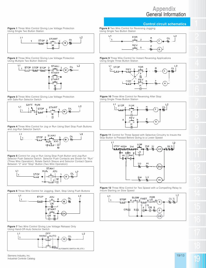
Control circuit schematics
AppendixGeneral Information
Siemens / Industrial Controls Previous folio: 19/26
Inc.talog
Figure 1 Three Wire Control Giving Low Voltage ProtectionUsing Single Two Button Station
Figure 8 Two Wire Control for Reversing JoggingUsing Single Two Button Station
Figure 3 Three Wire Control Giving Low Voltage Protectionwith Safe-Run Selector Switch
Figure 4 Three Wire Control for Jog or Run Using Start Stop Push Buttonsand Jog-Run Selector Switch
Figure 5 Control for Jog or Run Using Stop Push Button and Jog-RunSelector Push Selector Switch. Selector Push Contacts are Shown for “Run”(Three Wire Operation). Rotate Switch Sleeve and Selector Contact OpensBetween “2” and “Stop” Button (Two Wire Operation)
Figure 6 Three Wire Control for Jogging, Start, Stop Using Push Buttons
Figure 7 Two Wire Control Giving Low Voltage Release OnlyUsing Hand-Off-Auto Selector Switch
Figure 2 Three Wire Control Giving Low Voltage ProtectionUsing Multiple Two Button Stations
Figure 9 Three Wire Control for Instant Reversing ApplicationsUsing Single Three Button Station
Figure 10 Three Wire Control for Reversing After StopUsing Single Three Button Station
Figure 11 Control for Three Speed with Selective Circuitry to Insure theStop Button is Pressed Before Going to a Lower Speed
Figure 12 Three Wire Control for Two Speed with a Compelling Relay toInsure Starting on Slow Speed
10IC19_01-18.qxd 7/30/09 11:02 AM Page 19/13

19/14 Siemens Industry, Inc.Industrial Controls Catalog
SiemIndus
Control circuit schematics andwiring diagrams with transformers
AppendixGeneral Information
Siemens / Industrial Controls Previous folio: 19/27
Figure 13 Control for Three Speed with a Compelling Relay to InsureStarting on Low Speed
Size 0–21⁄2 Starter with Transformer and 3 Position Selector Switch
Size 0–21⁄2 Starter with Transformer and 2 Position Selector Switch
Size 0–21⁄2 Starter with Transformer and START-STOP Push Button
Figure 14 Control for Two Speed to Provide Automatic Acceleration fromLow to High Speed
Figure 15 Control for Two Speed to Provide Automatic Deceleration fromHigh to Low Speed
Figure 16 Control for Two Speed Reversing Starter Using Forward,Reverse, Stop Push Buttons and High-Low-Off Selector Switch
H1 transformer to L1 starterH4 transformer to L2 starterC on H-O-A to X1 transformerH on H-O-A to 3 or V on starterA by customer to external contact,
other side of external contact to 3 or V transformer by customer
X2 on starter to X2 on transformer
H1 transformer to L1 starterH4 transformer to L2 starterC on 0N-OFF to X1 transformerO on 0N-OFF to 3 or V on starterX2 on starter to X2 on transformer
H1 transformer to L1 starterH4 transformer to L2 starter1 on START-STOP to X1 transformer2 on START-STOP to 2 on starter3 on START-STOP to 3 or V on starterX2 on starter to X2 on transformer
AC
Non
indiload
MP
SC
Rev
sou
M
CR3
10IC19_01-18.qxd 7/30/09 11:02 AM Page 19/14
19/15 Inc.talog
Siemens Industry, Inc.Industrial Controls Catalog
Pilot control
AppendixGeneral Information
Siemens / Industrial Controls Previous folio: 19/28
AC Coil—NEMA Size 0–4 DC Coil—NEMA Size 0–4
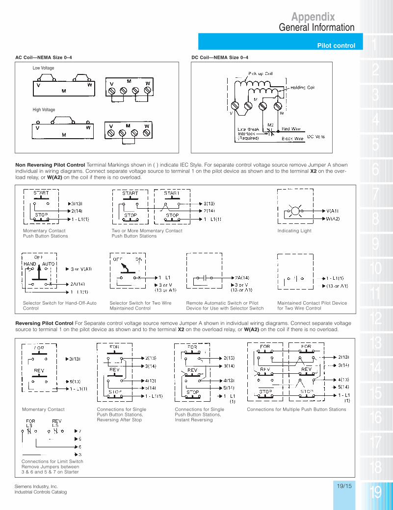
Non Reversing Pilot Control Terminal Markings shown in ( ) indicate IEC Style. For separate control voltage source remove Jumper A shownindividual in wiring diagrams. Connect separate voltage source to terminal 1 on the pilot device as shown and to the terminal X2 on the over-load relay, or W(A2) on the coil if there is no overload.
Low Voltage
High Voltage
Momentary ContactPush Button Stations
Selector Switch for Hand-Off-AutoControl
Selector Switch for Two WireMaintained Control
Remote Automatic Switch or PilotDevice for Use with Selector Switch
Maintained Contact Pilot Devicefor Two Wire Control
Two or More Momentary ContactPush Button Stations
Indicating Light
Reversing Pilot Control For Separate control voltage source remove Jumper A shown in individual wiring diagrams. Connect separate voltagesource to terminal 1 on the pilot device as shown and to the terminal X2 on the overload relay, or W(A2) on the coil if there is no overload.
Momentary Contact Connections for SinglePush Button Stations,Reversing After Stop
Connections for SinglePush Button Stations,Instant Reversing
Connections for Multiple Push Button Stations
Connections for Limit SwitchRemove Jumpers between3 & 6 and 5 & 7 on Starter
10IC19_01-18.qxd 7/30/09 11:02 AM Page 19/15

19/16 Siemens Industry, Inc.Industrial Controls Catalog
SiemIndus
Quick reference list
AppendixInternational Control Equipment (IEC)
Siemens / Industrial Controls Previous folio: new page
1) Standard Control Product - Not Considered ICE Product.
S
A
t
TT
A
Siemens is a manufacturer of equipment forthe global market and manufactures productsfor global applications. The products listed inSections 1 through 18 of this catalog are theproducts best suited for application in theU.S., Canada and Mexico.
There are a host of other Industrial Controlproducts that can be made available forexport applications or for replacement inOEM equipment imported in to the U.S. Themost common Siemens components are list-ed in the table below. We refer to these asIndustrial Control Equipment components orICE products.
If you are trying to identify a Siemens ID thatis not listed in the Catalog Number Index onpages 0/12 to 0/15 of this catalog or in thetable below, please contact our Call Center at800-241-4453 or 423-262-2522. The SiemensCall Center maintains an extensive data baseon all Siemens Operating Companies, andthey can direct you for the appropriate support.
Catalog NoPrefix
Description Catalog NoPrefix
Description Catalog NoPrefix
Description
2CC Low-Pressure Axial Ventilator Fan 3WY3 3WN Accessories 4FL Transformer Voltage Regulator2CF7 Medium-Pressure Radial-flow Fan 4AC Bell transformers, power supply units 4NC Window-type Current Transformer2CQ Medium-Pressure Axial Ventilator Fan 4AJ Standard Transformers 4PK Reactance coils with layer winding of
copper flat wire2CT Low-Pressure Axial Ventilator Fan 4AM Control Transformer 5SA DIAZED Fuse Links (E16) Miniature
Fuses 1)3KA Disconnect Switch 4AN Single-phase transformers YUI 1 (UI) 5SB DIAZED Fuse Links, Size II and III 1)3KE Disconnect Switch 4AP Transformer for rectifier operation 5SC DIAZED Fuse Links, Size IV and V 1)3KL Load Disconnect Switch w/Fuses 4AT Safety Isolation Transformer, 1 phase 5SD DIAZED Fuses3KM Load Disconnect Switch w/Fuses 4AU Safety Isolation Transformer, 3 phase 5SE Fuses 1)3KX 3KE4 Accessories 4AV Special Transformers and DC power
supplies5SF DIAZED Fuse Base
3KY 3KL Accessories 4AW Ring core transformers 5SG NEOZED & MINIZED FuseDisconnectors
3NA LV HRC Fuses 4AX Non-Siemens transformers 5SH DIAZED Fuse Accessories3NC SITOR Semiconductor fuse-links to
1000 V 1)4AY Transformer housings, accessories and
spare parts5SM Residual Current Protective Devices 1)
3ND1 LV HRC Fuses 4BT Transformer > 16 kVA, 1 Phase 5SQ Miniature Circuit Breaker3ND2 LV HRC Fuses 4BU Transformer > 16 kVA, 3 Phase 5SU Ground Fault and Line-Prot. Circuit
Breaker3NE SITOR Semiconductor fuse-links to
2500 V 1)4BV Special Transformers 5SV8 SFJ Fault and Line-Prot. Circuit Breaker
3NG1 LV HRC Fuses 4BX Transformer, 3-phase 5SW Wall Enclosure 3NH Fuse Bases 4CH Variac 1 Phase 5SZ Ground Fault Circuit Breakers3NJ Fused Disconnect Switch 4CJ Variac 3 Phase 5TE Toggle Switch3NP Fused Disconnect Switch 4CP Pillar-type, Variac, 1ph 5TG Signal Light
3NW1 Fuse Material to BS and NFStandards 1)
4CQ Pillar-type, Variac, 3ph 5TT Switch Relay
3NW6 Cylindrical Fuses 4EA Reactance Coils with Iron-Core Reactors 7KM Meters3NW8 Fuse Material to BS and NF
Standards4EF Reactance Coils with Iron-Core Reactors 7KT Time meters, impulsing meters and
accessories3NX Accessories and spare parts for NH-
fuses4EJ Reactance Coils with Iron-Core Reactors 7LF Digital time switches and accessories
3NY 3NP Accessories 4EM Single-phase reactance coils YEI 1 (EI) 7LQ Quarz-controlled time switches3TK Specialty Contactor 4EN9 Choke 7PV Timers
3UL22 Summation Current Transformers 4EP Line Reactor 7ZX Instruction Manual 1)3VU2 Phase Out Announced 4ET Single-phase reactance coils YUI 1 (UI) 8JH Distribution Enclosure Accessories
3VX Circuit Breaker Accessories andComponents
4EU Three-phase reactance coils YUI 2 (3UI) 8UB Handle Accessories
3WX 3W Accessories 4EV RFI Suppression Choke 8WC Distribution System Accessories3WY1 3WF Accessories 4FB Power supplies 8ZX Instruction Sheets 1)3WY2 3WE Accessories 4FK Magnetic Voltage Regulator 1 phase LZX Plug-in Relays 1)
10IC19_01-18.qxd 7/30/09 2:20 PM Page 19/16
19/17 Inc.talog
Siemens Industry, Inc.Industrial Controls Catalog
Spring loaded terminal technique
Appendix
Siemens / Industrial Controls Previous folio: 19/30
Spring Loaded Terminals
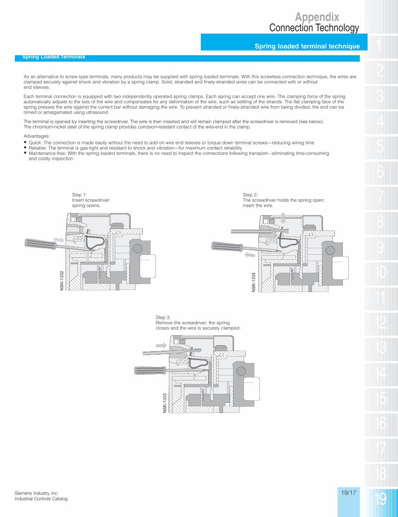
As an alternative to screw-type terminals, many products may be supplied with spring loaded terminals. With this screwless connection technique, the wires areclamped securely against shock and vibration by a spring clamp. Solid, stranded and finely-stranded wires can be connected with or without end sleeves.
Each terminal connection is equipped with two independently operated spring clamps. Each spring can accept one wire. The clamping force of the spring automatically adjusts to the size of the wire and compensates for any deformation of the wire, such as settling of the strands. The flat clamping face of thespring presses the wire against the current bar without damaging the wire. To prevent stranded or finely-stranded wire from being divided, the end can betinned or amalgamated using ultrasound.
The terminal is opened by inserting the screwdriver. The wire is then inserted and will remain clamped after the screwdriver is removed (see below). The chromium-nickel steel of the spring clamp provides corrosion-resistant contact of the wire-end in the clamp.
Advantages:• Quick: The connection is made easily without the need to add on wire end sleeves or torque down terminal screws—reducing wiring time• Reliable: The terminal is gas-tight and resistant to shock and vibration—for maximum contact reliability• Maintenance-free: With the spring loaded terminals, there is no need to inspect the connections following transport—eliminating time-consuming
and costly inspection
Step 1:Insert screwdriver;spring opens.
Step 2:The screwdriver holds the spring open;insert the wire.
Step 3:Remove the screwdriver; the springcloses and the wire is securely clamped.
aton
r atensase
of
1)
aker
es
Connection Technology
10IC19_01-18.qxd 7/30/09 2:20 PM Page 19/17

19/18 Siemens Industry, Inc.Industrial Controls Catalog
Standard terms andconditions of sale (10/1/2004)
AppendixSiemens Energy & Automation, Inc. (Seller)
Siemens / Industrial Controls Previous folio: 19/32
1. WARRANTY - (a) Seller warrants that on the date of shipment the goods are of
the kind and quality described herein and are free of non-conformities in workmanship
and material. This warranty does not apply to goods delivered by Seller but
manufactured by others.
(b) Buyer's exclusive remedy for a nonconformity in any item of the goods shall be the
repair or the replacement (at Seller's option) of the item and any affected part of the
goods. Seller's obligation to repair or replace shall be in effect for a period of one (1)
year from initial operation of the goods but not more than eighteen (18) months from
Seller's shipment of the goods, provided Buyer has sent written notice within that
period of time to Seller that the goods do not conform to the above warranty. Repaired
and replacement parts shall be warranted for the remainder of the original period of
notification set forth above, but in no event less than 12 months from repair or
replacement. At its expense, Buyer shall remove and ship to Seller any such
nonconforming items and shall reinstall the repaired or replaced parts. Buyer shall
grant Seller access to the goods at all reasonable times in order for Seller to
determine any nonconformity in the goods. Seller shall have the right of disposal of
items replaced by it. If Seller is unable or unwilling to repair or replace, or if repair or
replacement does not remedy the nonconformity, Seller and Buyer shall negotiate an
equitable adjustment in the contract price, which may include a full refund of the
contract price for the nonconforming goods.
(c) SELLER HEREBY DISCLAIMS ALL OTHER WARRANTIES, EXPRESS OR
IMPLIED, EXCEPT THAT OF TITLE. SPECIFICALLY, IT DISCLAIMS THE IMPLIED
WARRANTIES OF MERCHANTABILITY, FITNESS FOR A PARTICULAR PURPOSE,
COURSE OF DEALING AND USAGE OF TRADE.
(d) Buyer and successors of Buyer are limited to the remedies specified in this article
and shall have no others for a nonconformity in the goods. Buyer agrees that these
remedies provide Buyer and its successors with a minimum adequate remedy and are
their exclusive remedies, whether Buyer's or its successors' remedies are based on
contract, warranty, tort (including negligence), strict liability, indemnity, or any other
legal theory, and whether arising out of warranties, representations, instructions,
installations, or non-conformities from any cause.
(e) Note: This article 1 does not apply to any software which may be furnished by
Seller. In such cases, the attached Software License Addendum applies.
2. PATENTS - Seller shall pay costs and damages finally awarded in any suit against
Buyer or its vendees to the extent based upon a finding that the design or construction
of the goods as furnished infringes a United States patent (except infringement
occurring as a result of incorporating a design or modification at Buyer's request),
provided that Buyer promptly notifies Seller of any charge of infringement, and Seller
is given the right at its expense to settle such charge and to defend or control the
defense of any suit based upon such charge. Seller shall have no obligation hereunder
with respect to claims, suits or proceedings, resulting from or related to, in whole or in
part, (i) the use of software or software documentation, (ii) compliance with Buyer's
specifications, (iii) the combination with, or modification of, the goods after delivery by
Seller, or (iv) the use of the goods, or any part thereof, in the practice of a process.
THIS ARTICLE SETS FORTH SELLER'S ENTIRE LIABILITY WITH RESPECT TO
PATENTS.
3. PERFORMANCE; DELAYS - Timely performance by Seller is contingent upon
Buyer's supplying to Seller, when needed, all required technical information and data,
including drawing approvals, and all required commercial documentation. If Seller
suffers delay in performance due to any cause beyond its reasonable control, the time
of performance shall be extended a period of time equal to the period of the delay and
its consequences. Seller will give to Buyer notice within a reasonable time after Seller
becomes aware of any such delay.
4. SHIPMENT, TITLE AND RISK OF LOSS - Unless the delivery terms of this
contract expressly provide for F.O.B. destination, shipping/delivery will be F.O.B.
Seller's point of shipment with title to the goods and risk of loss or damage passing to
Buyer at that point. Buyer will be responsible for shipment during transit and for filing
any damage or loss claims directly with the carrier. Seller may make partial
shipments.
5. TAXES - Any applicable duties or sales, use, excise, value-added or similar taxes
will be added to the price and invoiced separately (unless an acceptable exemption
certificate is furnished).
6. TERMS OF PAYMENT - (a) Unless otherwise stated, all payments shall be in
United States dollars, and a pro rata payment shall become due as each shipment is
made. If shipment is delayed by Buyer, date of notice of readiness for shipment shall
be deemed to be date of shipment for payment purposes.
(b) On late payments, the contract price shall, without prejudice to Seller's right to
immediate payment, be increased by 1 1/2% per month on the unpaid balance, but not
to exceed the maximum permitted by law.
(c) If any time in Seller's judgment Buyer is unable or unwilling to meet the terms
specified, Seller may require satisfactory assurance or full or partial payment as a
condition to commencing or continuing manufacture or making shipment, and may, if
shipment has been made, recover the goods from the carrier, pending receipt of such
assurances.
7. NONCANCELLATION - Buyer may not cancel or terminate for convenience, or
direct suspension of manufacture, except with Seller's written consent and then only
upon terms that will compensate Seller for its engineering, fabrication and purchasing
charges and any other costs relating to such cancellation, termination or suspension,
plus a reasonable amount for profit.
8. NUCLEAR - Buyer represents and warrants that the goods covered by this
contract shall not be used in or in connection with a nuclear facility or application. If
Buyer is unable to make such representation and warranty, then Buyer agrees to
indemnify and hold harmless Seller and to waive and require its insurers to waive all
right of recovery against Seller for any damage, loss, destruction, injury or death
resulting from a “nuclear incident”, as that term is defined in the Atomic Energy Act of
1954, as amended, whether or not due to Seller's negligence.
9. LIMITATION OF LIABILITY - NEITHER SELLER, NOR ITS SUPPLIERS SHALL
BE LIABLE, WHETHER IN CONTRACT, WARRANTY, FAILURE OF A REMEDY TO
ACHIEVE ITS INTENDED OR ESSENTIAL PURPOSES, TORT (INCLUDING
NEGLIGENCE), STRICT LIABILITY, INDEMNITY OR ANY OTHER LEGAL THEORY,
FOR LOSS OF USE, REVENUE OR PROFIT, OR FOR COSTS OF CAPITAL OR OF
SUBSTITUTE USE OR PERFORMANCE, OR FOR INDIRECT, SPECIAL,
LIQUIDATED, INCIDENTAL OR CONSEQUENTIAL DAMAGES, OR FOR ANY
OTHER LOSS OR COST OF A SIMILAR TYPE, OR FOR CLAIMS BY BUYER FOR
DAMAGES OF BUYER'S CUSTOMERS. SELLER'S MAXIMUM LIABILITY UNDER
THIS CONTRACT SHALL BE THE CONTRACT PRICE. BUYER AND SELLER
AGREE THAT THE EXCLUSIONS AND LIMITATIONS SET FORTH IN THIS
ARTICLE ARE SEPARATE AND INDEPENDENT FROM ANY REMEDIES WHICH
BUYER MAY HAVE HEREUNDER AND SHALL BE GIVEN FULL FORCE AND
EFFECT WHETHER OR NOT ANY OR ALL SUCH REMEDIES SHALL BE DEEMED
TO HAVE FAILED OF THEIR ESSENTIAL PURPOSE.
10. GOVERNING LAW AND ASSIGNMENT - The laws of the State of Georgia shall
govern the validity, interpretation and enforcement of this contract, without regard to
its conflicts of law principles. The application of the United Nations Convention on
Contracts for the International Sale of Goods shall be excluded. Assignment may be
made only with written consent of both parties; provided, however, Seller may assign
to its affiliate without Buyer's consent.
11. ATTORNEY FEES - Buyer shall be liable to Seller for any attorney fees and costs
incurred by Seller in enforcing any of its rights hereunder.
12. DISPUTES - Either party may give the other party written notice of any dispute
arising out of or relating to this contract and not resolved in the normal course of
business. The parties shall attempt in good faith to resolve such dispute promptly by
negotiations between executives who have authority to settle the dispute. If the matter
has not been resolved within 60 days of the notice, either party may initiate non-
binding mediation of the dispute.
13. STATUTE OF LIMITATIONS - To the extent permitted by applicable law, any
lawsuit for breach of contract, including breach of warranty, arising out of the
transactions covered by this contract, must be commenced not later than twelve (12)
months from the date the cause of action accrued.
14. PRICES - In the event of a price increase or decrease, the price of goods on order
will be adjusted to reflect such increase or decrease. This does not apply to a
shipment held by request of Buyer. Goods already shipped are not subject to price
increase or decrease. Orders on a bid or contract basis are not subject to this article.
Seller's prices include the costs of standard domestic packing only. Any deviation
from this standard packing (domestic or export), including U.S. Government sealed
packing, will result in extra charges. To determine such extra charges, consult Seller's
sales offices. Orders of less than $400 will be charged a $25 handling fee.
15. ADDITIONAL TERMS OF PAYMENT - Invoice payment terms are as shown on
latest discount sheets as issued from time to time. Cash discounts are not applicable
to notes or trade acceptances, to prepaid transportation charges when added to
Seller's invoices or to discountable items if there are undisputed past due items on the
account. Portions of an invoice in dispute should be deducted and the balance
remitted with a detailed explanation of the deduction. Cash discounts will only be
allowed on that portion of the invoice paid within the normal discount period.
16. CHANGES IN LAWS AND REGULATIONS - Seller's prices and timely
performance are based on all applicable laws, rules, regulations, orders, codes,
standards or requirements of governmental authorities effective on the date of Seller's
proposal. Any change to any law, rule, regulation, order, code, standard or
requirement which requires any change hereunder shall entitle Seller to an equitable
adjustment in the prices and any time of performance.
10IC19_01-18.qxd 7/30/09 11:03 AM Page 19/18
Recommended


![Index [cmsapps.sea.siemens.com]cmsapps.sea.siemens.com/controls/icc2010... · are suited for almost any application. ... and/or Siemens circuit breaker assemblies. The Siemens Fast](https://img.pdfslide.us/doc/110x75/5aa9e62c7f8b9a9a188d8968/index-suited-for-almost-any-application-andor-siemens-circuit-breaker.jpg)