®
Using Occupancy Sensing Switch with Maestro® Companion Switch
Application Note #435Revision B May 2012
1 Technical Support — 800.523.9466
LutronR Occupancy & Vacancy motion sensors are passive infrared (PIR) sensors that automatically control lights. These sensors detect the heat from occupants moving within an area to determine when the space is occupied. The sensors then control the lights automatically turning them off or on, providing convenience and increased energy savings.
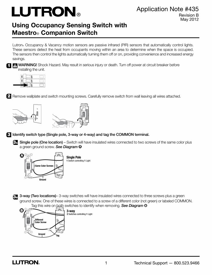
WARNING! Shock Hazard. May result in serious injury or death. Turn off power at circuit breaker before installing the unit.
Remove wallplate and switch mounting screws. Carefully remove switch from wall leaving all wires attached.
Identify switch type (Single pole, 3-way or 4-way) and tag the COMMON terminal.
Single pole (One location) – Switch will have insulated wires connected to two screws of the same color plus a green ground screw. See Diagram A
3-way (Two locations)– 3-way switches will have insulated wires connected to three screws plus a green ground screw. One of these wires is connected to a screw of a different color (not green) or labeled COMMON. Tag this wire on both switches to identify when removing. See Diagram B
1
2
3
3A
3B
!
Single PoleA1 Switch controlling 1 Light
Ground
Same Color Screws
3-wayB2 Switches controlling 1 Light
Ground
Different Color Screw
Tag

Application Note #435
2 www.lutron.com
4-way (Three or more locations) – 4-way switches will have insulated wires connected to four screws plus a green ground screw. Tag either set of two same-color insulated wires that are connected to different-colored screws (on the same side of the switch). Follow this procedure for each 4-way switch. See Diagram C
Disconnect wires from the switches removed in step 2. The switches may have two wires attached to the same screw. Tape these two wires together before disconnecting.
Connect Occupancy Sensing Switch and Companion Switches
Single pole (One location) - Existing switch will be replaced with an Occupancy Sensing Switch.
• Formodelswithoutaneutral(white)wire,(OPS5M,VPS5M,OPS6M2-DV,andVPS6M2-DV)Connectgreenandbare ground wire on Occupancy Sensing Switch to bare copper or green wire in wallbox.
• Formodelswithaneutral(white)wire,(OPS6M2N-DV,VPS6M2N-DV)ConnectbaregroundwireonOccupancySensing Switch to bare copper or green wire in wallbox.
• ConnectwhitewireonOccupancySensingSwitchtowhitewire(neutral)inwallbox(OPS6M2N-DV,VPS6M2N-DV)
• ConnectoneoftheremainingwiresremovedfromswitchtoblackwireonOccupancySensingSwitch.
• ConnectremainingwireremovedfromswitchtotheotherblackwireonOccupancySensingSwitch.
• Bluewireisnotusedinasingle-polecircuit.Capbluewire.
Push-in TerminalScrew Terminal
4
5
3C
5A
C4-way3 or more Switches controlling 1 Light.
Tags
Same Color
2 Switches will be 3-way, others will be 4-way.
Different Color ScrewsGround
Green
GroundBare
Black
Black
Blue
Occupancy Sensing Switch
Neutral
LoadBare Green
Blue
BlackBlackLive
Ground
White
GroundBare
Black
Black
Blue
Occupancy Sensing Switch
Neutral
LoadBare White
Blue
BlackBlackLive
Ground
-OPS5M, -VPS5M, -OPS6M2-DV, and -VPS6M2-DV -OPS6M2N-DV, and -VPS6M2N-DV

Application Note #435
3 www.lutron.com
3-way (Two locations)
NOTE: 120 V~ circuits use MA -AS/ MSC-AS Companion Switches 240 / 277 V~ circuits use MA -AS-277/ MSC-AS-277 Companion Switches
Wire the Occupancy Sensing Switch
• Formodelswithoutaneutral(white)wire,(OPS5M,VPS5M,OPS6M2-DV,andVPS6M2-DV)Connectgreenandbare ground wire on Occupancy Sensing Switch to bare copper or green wire in wallbox.
• Formodelswithaneutral(white)wire,(OPS6M2N-DV,VPS6M2N-DV)ConnectbaregroundwireonOccupancySensing Switch to bare copper or green wire in wallbox.
• ConnectwhitewireonOccupancySensingSwitchtowhitewire(neutral)inwallbox(OPS6M2N-DV,VPS6M2N-DV)
• ConnecttaggedwireremovedfromswitchtooneoftheblackwiresonOccupancySensingSwitch.
• ConnectoneoftheremainingwiresremovedfromswitchtotheotherblackwireonOccupancySensingSwitch.
• Connectremainingwireremovedfromswitch(notecolor)tobluewireonOccupancySensingSwitch.
Wire the Companion Switch
• ConnectgreengroundwireonCompanionSwitchtobarecopperorgreenwireinwallbox.
• ConnecttaggedwireremovedfromswitchtoblackscrewterminalonCompanionSwitch.
• ConnectthesamecolorwireconnectedtothebluewireonOccupancySensingSwitch(colornotedabove)totheblue screw terminal on Companion Switch.
• ConnectremainingwireremovedfromswitchtobrassscrewterminalonCompanionSwitch.
See wiring diagrams on next page.
5B
White
Blue
Ground
Black
Black
Occupancy Sensing Switch Bare
Ground
Tag
Green wire
Black screw
Brass screw Blue screw
Companion Switch
-OPS6M2N-DV, and -VPS6M2N-DV-OPS5M, -VPS5M, -OPS6M2-DV, and -VPS6M2-DV
Green
Blue
Ground
Black
Black
Occupancy Sensing Switch Bare
Tag Tag

Application Note #435
4 www.lutron.com
Screw Color (120 V~ Companion Switch)Brass Blue Black
Wire Color (277 V~ Companion Switch)Black Wire Blue Wire Black Wire
Occupancy SensingSwitch (Wires)
Companion Switch
Switc
h Ty
pe
Prod
uct K
ey
Neutral
BareGreen Green
Line side Load side
Ground Ground
Load
Live
Blue
BlackBlack
Neutral
Bare White Green
Line side Load side
Ground Ground
Load
Live
Blue
BlackBlack
5B Wiring Diagrams
Neutral
Green GreenBare
Line side Load side
Ground GroundLoad
Blue
BlackBlackLive
Neutral
Green whiteBare
Line side Load side
GroundGround Load
Blue
BlackBlackLive
OR OR
NOTE: Maximum wire length between the Occupancy Sensing Switch and the Companion Switch (Totalblueterminalwirelength)is150ft(46m).
-OPS6M2N-DV, and -VPS6M2N-DV-OPS5M, -VPS5M, -OPS6M2-DV, and -VPS6M2-DV

Application Note #435
5 www.lutron.com
4-way (Three or more locations)
NOTE: The Occupancy Sensing Switch can be installed in any of the locations (choose the location where the sensor will have optimal coverage of the space). The occupancy sensing switch and/or companion switches can replace a 4-way switch or 3-way switch (4-way applications typically include both 4-way and 3-way switches).
Wire the Occupancy Sensing Switch replacing a 4-way switch
• Formodelswithoutaneutral(white)wire,(OPS5M,VPS5M,OPS6M2-DV,andVPS6M2-DV)Connectgreenandbare ground wire on Occupancy Sensing Switch to bare copper or green wire in wallbox.
• Formodelswithaneutral(white)wire,(OPS6M2N-DV,VPS6M2N-DV)ConnectbaregroundwireonOccupancySensing Switch to bare copper or green wire in wallbox.
• ConnectwhitewireonOccupancySensingSwitchtowhitewire(neutral)inwallbox(OPS6M2N-DV,VPS6M2N-DV)
• Connectbothtaggedwires(notecolor)removedfrom4-wayswitchtobluewireonOccupancySensingSwitch.
• ConnectoneoftheremainingwiresremovedfromswitchtooneoftheblackwiresonOccupancySensingSwitch.
• ConnectremainingwireremovedfromswitchtootherblackwireonOccupancySensingSwitch.
Wire the Companion Switch replacing a 4-way switch
• ConnectgreenwireonCompanionSwitchtobarecopperorgreenwireinwallbox.
• Connectbothtaggedwires(notewirecolor)removedfrom4-wayswitchtobluescrewterminalonCompanionSwitch (one wire to screw terminal the other to push-in terminal).
• ConnectoneoftheremainingwiresremovedfromswitchtoblackscrewterminalonCompanionSwitch.
• ConnectremainingwireremovedfromswitchtobrassscrewterminalonCompanionSwitch.
NOTE: Repeat for each Companion Switch replacing a 4-way switch.
See wiring diagrams on page 7.
Occupancy Sensing Switch
Green Ground
Blue
Black
Black
Bare
Companion Switch
Ground
Green wire
Black screw
Brass screwBlue screw
Tags
5C
-OPS5M, -VPS5M, -OPS6M2-DV, and -VPS6M2-DV -OPS6M2N-DV, and -VPS6M2N-DV
Occupancy Sensing Switch
White
Ground
Blue
Black
Black
Bare

Application Note #435
6 www.lutron.com
4-way (Three or more location control)
Wire the Occupancy Sensing Switch replacing a 3-way switch
• Formodelswithoutaneutral(white)wire,(OPS5M,VPS5M,OPS6M2-DV,andVPS6M2-DV)Connectgreenandbare ground wire on Occupancy Sensing Switch to bare copper or green wire in wallbox.
• Formodelswithaneutral(white)wire,(OPS6M2N-DV,VPS6M2N-DV)ConnectbaregroundwireonOccupancySensing Switch to bare copper or green wire in wallbox.
• ConnectwhitewireonOccupancySensingSwitchtowhitewire(neutral)inwallbox(OPS6M2N-DV,VPS6M2N-DV)
• ConnecttaggedwireremovedfromswitchtooneoftheblackwiresonOccupancySensingSwitch.
• ConnectsamecolorwireconnectedtobluescrewterminalonCompanionSwitchthatreplaced4-wayswitch(color noted above) to blue wire on Occupancy Sensor Switch.
• ConnectremainingwireremovedfromswitchtotheotherBlackwireonOccupancySensingSwitch.
Wire the Companion Switch(es) replacing a 3-way switch
• ConnectgreengroundwireonCompanionSwitchtobarecopperorgreenwireinwallbox.
• ConnecttaggedwireremovedfromswitchtotheblackscrewterminalonCompanionSwitch.
• ConnectsamecolorwireconnectedtobluewireonOccupancySensorSwitchthatreplaced4-wayswitch(colornoted above) to blue screw terminal on Companion Switch.
• ConnectremainingwireremovedfromswitchtothebrassscrewterminalonCompanionSwitch. (See Instructions that came with Companion Switch for more information)
NOTE: Repeat for each Companion Switch replacing a 3-way switch.
Green
Ground
Companion Switch
Black screw
Brass screw
Blue screw
5C
Occupancy Sensing Switch
Green
Ground
BlueBlack
Black
Bare
Occupancy Sensing Switch
White
Ground
Blue
Black
Black
Bare
See wiring diagrams on next page.
-OPS5M, -VPS5M, -OPS6M2-DV, and -VPS6M2-DV -OPS6M2N-DV, and -VPS6M2N-DV

Application Note #435
7 www.lutron.com
Wiring Diagrams5C
OR OR
OR OR
Green Green Green
Line side Load side
Neutral
Ground
Load
Live
Blue
BlackBlack
Bare
Ground Ground
White Green Green
Line side Load side
Neutral
Ground
Load
Live
Blue
BlackBlack
Bare
Ground
Ground
4-way
4-way
Green Green GreenBare
Line side Load side
Neutral
Ground Ground Ground Load
Live
Blue
BlackBlack
4-way
Green Green WhiteBare
Line side Load side
Neutral
Ground GroundGround
Load
Live
Blue
BlackBlack
Green Green Green
Line side Load side4-way
Neutral
Ground Ground
Load
Live
Blue
Black
Bare
Ground
Black
Blue
Green White Green
Line side Load side4-way
Neutral
Ground Ground
Load
Live
Blue
Black
Bare
Ground
Black
Blue
Screw Color (120 V~ Companion Switch)Brass Blue Black
Wire Color (277 V~ Companion Switch)Black Wire Blue Wire Black Wire
Occupancy SensingSwitch (Wires)
Companion Switch
Switc
h Ty
pe
Prod
uct K
ey
NOTE: Maximum wire length between the Occupancy Sensing Switch and the Companion Switch (totalblueterminalwirelength)is150ft(46m).
-OPS6M2N-DV, and -VPS6M2N-DV-OPS5M, -VPS5M, -OPS6M2-DV, and -VPS6M2-DV

Application Note #435
Lutron Electronics Co., Inc.7200 Suter RoadCoopersburg, PA 18036-1299 U.S.A.P/N 048-435 Rev. B 05/2012
8
Lutron Contact Numbers
WORLD HEADQUARTERS USA
Lutron Electronics Co., Inc. 7200 Suter Road Coopersburg, PA 18036-1299 TEL: +1.610.282.3800 FAX: +1.610.282.1243 Toll-Free: 1.888.LUTRON1 Technical Support: 1.800.523.9466
North & South America Technical Hotlines
USA, Canada, Caribbean: 1.800.523.9466 Mexico: +1.888.235.2910 Central/South America: +1.610.282.6701
EUROPEAN HEADQUARTERS United Kingdom
Lutron EA Ltd. 6 Sovereign Close London, E1W 3JF United Kingdom TEL: +44.(0)20.7702.0657 FAX: +44.(0)20.7480.6899 FREEPHONE (UK): 0800.282.107 Technical Support: +44.(0)20.7680.4481
ASIAN HEADQUARTERS Singapore
Lutron GL Ltd. 15 Hoe Chiang Road #07-03, Tower 15 Singapore 089316 TEL: +65.6220.4666 FAX: +65.6220.4333 Technical Support: 800.120.4491
Asia Technical HotlinesNorthern China: 10.800.712.1536 Southern China: 10.800.120.1536 Hong Kong: 800.901.849 Indonesia: 001.803.011.3994 Japan: +81.3.5575.8411 Macau: 0800.401 Taiwan: 00.801.137.737 Thailand: 001.800.120.665853 Other Countries: +65.6220.4666
Push wires carefully into wallbox and install Occupancy Sensing Switch and all Companion Switches. Leave wall plate off Occupancy Sensing Switch if custom settings are desired. See Occupancy Sensing Switch installation instructions for details on custom settings.
Turn power On at circuit breaker.
NOTE: Once power has been restored, the Occupancy Sensing Switch can be manually turned on or off after 30 seconds but will not automatically control the load for the first 2 minutes.
6
7
Lutron and Maestro are registered trademarks of Lutron Electronics Co., Inc. © 2012 Lutron Electronics Co., Inc.
Recommended