Akai APC40 Mk2 Communications Protocol
Version 1.2
Table of ContentsIntroduction ....................................................................................................................... 3 Scope ............................................................................................................................... 3 Glossary ........................................................................................................................... 3 General ............................................................................................................................. 3 USB Ports ......................................................................................................................... 3
Akai APC40 Mk2 Port .............................................................................................. 3 General Format of MIDI System Exclusive message ....................................................... 3 “Universal” MIDI messages .............................................................................................. 4
Device Inquiry .......................................................................................................... 4 Format of Device Inquiry Request message from Host to Device ....................... 4 Format of response from APC40 Mk2 to Device Inquiry message ...................... 5
The Note-On Message ............................................................................................. 7 Format of Note-On message ............................................................................... 7
The Note-Off Message ............................................................................................. 7 Format of Note-Off message ............................................................................... 7
The Controller Change Message ............................................................................. 7 Format of Controller Change message ................................................................ 7
“Akai Specific MIDI messages” ......................................................................................... 8 Device Setup Message ............................................ Error! Bookmark not defined.
Format of Device setup message from Host to DeviceError! Bookmark not defined. There is no inbound response to this message. .. Error! Bookmark not defined.
Introduction Message ............................................................................................... 8 Format of Introduction message from Host to Device .......................................... 8 Format of response from APC40 Mk2 Introduction message .............................. 9

APC40 Mk 2 LED Map ........................................................................................... 10 Outbound APC40 Mk2 Sysex Message Types .......................................................... 10
Outbound Message Type 0: Introduction ............................................................... 10 Format of Type 0 outbound message ................................................................ 12
Outbound Message Type 1: LEDs. ........................................................................ 13 Format of Type 1 outbound Midi note-on messages ......................................... 13 Format of Type 1 outbound Midi note-off messages ......................................... 13 Assignment of Note number messages to LEDs. Note 0x30 to 0x39 use MIDI Channel 0 to 7 to indicate Tracks 1-8. All other note values ignore the MIDI Channel. ............................................................................................................. 13
Outbound Message Type 2: Controller Value Update messages .......................... 22 MIDI Controller message ................................................................................... 23 Assignment of controller numbers to absolute controllers ................................. 23
Interpretation of LED Ring Types ........................................................................... 26 Communications from device to PC Host - “Inbound” messages ................................... 29
Inbound Standard MIDI Message types ..................................................................... 29 Type NOTE1: Note-on/Note-off messages ............................................................ 29
Midi note-on messages ...................................................................................... 30 Midi note-off messages ...................................................................................... 30
Type CC1: Absolute Controller messages ............................................................. 34 MIDI Controller message ................................................................................... 34 Assignment of controller numbers to absolute controllers ................................. 34
Type CC2: Relative Controller messages .............................................................. 36 MIDI Controller message ................................................................................... 37 Interpretation of MIDI Controller values for Relative Controllers ........................ 37 Assignment of controller numbers to relative controllers ................................... 37
Document History ........................................................................................................... 38

Akai APC40 Mk2 Communication Protocol
Version 1.2 – January 19, 2015 Page 3
Introduction APC40 Mk2 is a USB bus-powered, compact controller for Ableton Live and other software applications. It features a 5x8 grid of RGB launch clips, 9 faders, and 16 knobs with LED rings for software control. It features an array of UI buttons that will be used in conjunction with Ableton Live and other software.
Scope This document describes the format of messages between the APC40 Mk2 and the PC/Mac Host.
Glossary Outbound: The term “outbound” is used to describe messages sent from the PC Host
to the device, i.e. from the viewpoint of the PC Host. Inbound: The term “inbound” is used to describe messages sent from the device to the PC Host, i.e. from the viewpoint of the PC Host.
General
USB Ports
Akai APC40 Mk2 Port This port handles all the Ableton specific messaging. All controls will communicate over this port.
General Format of MIDI System Exclusive message The System Exclusive messages exchanged between the PC Host and the device will be of the following format:
Byte Number Value Description

Akai APC40 Mk2 Communication Protocol
Version 1.2 – January 19, 2015 Page 4
Byte Number Value Description
1 0xF0 MIDI System exclusive message start
2 0x47 Manufacturers ID Byte
3 0x7F System Exclusive Device ID
4 0x29 Product model ID
5 <Message ID> Message type identifier
6 <DataLengthMS> Number of data bytes to follow (most significant)
7 <DataLengthLS> Number of data bytes to follow (least significant)
8 n data bytes Data field – n bytes long
n+8 0xF7 MIDI System exclusive message terminator The Manufacturer's identity field will contain the one-byte code allocated to Akai Professional, which is 0x47. The System Exclusive Device ID is typically used to select between multiple devices connected to the same PC Host. In our application, we only expect one APC40 Mk2 to be connected at any one time and so a value of 0x7F (broadcast) should be used (and it is unlikely that the APC40 Mk2 will pay any regard to this field). If the situation changes and we find that it is appropriate to have more than one APC40 Mk2 connected to a PC Host, this field can be used to determine which device is the intended recipient of the message and we can then determine how this parameter is assigned on each connected device. The Message type identifier identifies the type of the message. This field will determine the size of the data field and how the data field bytes should be interpreted. There will be a number of data bytes in the message. Different message types are likely to have a different data field lengths/formats.
“Universal” MIDI messages
Device Inquiry APC40 Mk2 supports the convention of Device Inquiry
Format of Device Inquiry Request message from Host to Device
Byte Number Value Description

Akai APC40 Mk2 Communication Protocol
Version 1.2 – January 19, 2015 Page 5
Byte Number Value Description
1 0xF0 MIDI System exclusive message start
2 0x7E Non-Realtime Message
3 <MIDI Channel> Channel to inquire. 0x00 – 0x0F. If set to 0x0x7F inquiry is omni.
4 0x06 Inquiry Message
5 0x01 Inquiry Request
6 0xF7 MIDI System exclusive message terminator The APC40 Mk2 will respond to a Device Inquiry Request message with the following message:
Format of response from APC40 Mk2 to Device Inquiry message
Byte Number Value Description
1 0xF0 MIDI System exclusive message start
2 0x7E Non-Realtime Message
3 <MIDI Channel> Common MIDI channel setting
4 0x06 Inquiry Message
5 0x02 Inquiry Response
6 0x47 Manufacturers ID Byte
7 0x29 Product model ID
8 0x00 Number of data bytes to follow (most significant)
9 0x19 Number of data bytes to follow (least significant)
10 <Version1> Software version major most significant
11 <Version2> Software version major least significant
12 <Version3> Software version minor most significant
13 <Version4> Software version minor least significant

Akai APC40 Mk2 Communication Protocol
Version 1.2 – January 19, 2015 Page 6
Byte Number Value Description
14 <DeviceID> System Exclusive Device ID
15 <Serial1> <Reserved, Set to 0x00 in this application>
16 <Serial2> <Reserved, Set to 0x00 in this application>
17 <Serial3> <Reserved, Set to 0x00 in this application>
18 <Serial4> <Reserved, Set to 0x00 in this application>
19 <Manufacturing1> Manufacturing Data byte 1
20 <Manufacturing2> Manufacturing Data byte 2
21 <Manufacturing3 Manufacturing Data byte 3
22 <Manufacturing4> Manufacturing Data byte 4
23 <Manufacturing5> Manufacturing Data byte 5
24 <Manufacturing6> Manufacturing Data byte 6
25 <Manufacturing7> Manufacturing Data byte 7
26 <Manufacturing8> Manufacturing Data byte 8
27 <Manufacturing9> Manufacturing Data byte 9
28 <Manufacturing10> Manufacturing Data byte 10
29 <Manufacturing11> Manufacturing Data byte 11
30 <Manufacturing12> Manufacturing Data byte 12
31 <Manufacturing13> Manufacturing Data byte 13
32 <Manufacturing14> Manufacturing Data byte 14
33 <Manufacturing15> Manufacturing Data byte 15
34 <Manufacturing16> This byte should be set to 0x00.
35 0xF7 MIDI System exclusive message terminator

Akai APC40 Mk2 Communication Protocol
Version 1.2 – January 19, 2015 Page 7
The Note-On Message
Format of Note-On message
Byte Number Value Description
1 0x9<Chan> MIDI Note on, where Chan is a value from 0 – F and specifies the MIDI channel.
2 <Note Number> Note Number
3 <Velocity> Velocity of the key-press. For controls that are not velocity sensitive, this value should be 0x7F
The Note-Off Message
Format of Note-Off message
Byte Number Value Description
1 0x8<Chan> MIDI Note on, where Chan is a value from 0 – F and specifies the MIDI channel.
2 <Note Number> Note Number
3 <Velocity> Velocity of the key-release. For controls that are not velocity sensitive, this value should be 0x7F
The Controller Change Message APC40 Mk2 sends MIDI Controller Change messages from its buttons and knobs. It can also receive Controller Change messages to turn LEDs On/Off
Format of Controller Change message
Byte Number Value Description
1 0xB<Chan> MIDI Controller Change, where Chan is a value from 0 – F and specifies the MIDI channel.
2 <Controller> Note Number

Akai APC40 Mk2 Communication Protocol
Version 1.2 – January 19, 2015 Page 8
Byte Number Value Description
3 <Value> Velocity of the key-release. For controls that are not velocity sensitive, this value should be 0x7F
“Akai Specific MIDI messages”
Introduction Message This message is sent before any other device-specific message (i.e. other than Device Enquiry). It instructs the APC40 Mk2 to perform the necessary initialization and informs the firmware of the version number of the application in order that changes in the application can be catered for in the APC40 Mk2 firmware.
Format of Introduction message from Host to Device
Byte Number Value Description
1 0xF0 MIDI System exclusive message start
2 0x47 Manufacturers ID Byte
3 0x7F System Exclusive Device ID
4 0x29 Product model ID
5 0x60 Message type identifier
6 0x00 Number of data bytes to follow (most significant)
7 0x04 Number of data bytes to follow (least significant)
8 0x00 Application/Configuration identifier
9 <Version High> PC application Software version major
10 <Version Low> PC application Software version minor
11 <Bugfix Level> PC Application Software bug-fix level
12 0xF7 MIDI System exclusive message terminator

Akai APC40 Mk2 Communication Protocol
Version 1.2 – January 19, 2015 Page 9
Format of response from APC40 Mk2 Introduction message
Byte number Value Description
1 0xF0 MIDI System exclusive message start
2 0x47 Manufacturers ID Byte
3 0x7F System Exclusive Device ID
4 0x29 Product model ID
5 0x61 Message type identifier
6 0x00 Number of data bytes to follow (most significant)
7 0x04 Number of data bytes to follow (least significant)
8 <Slider #1 Value> Sends the current value of Knob #1.
9 <Slider #2 Value> Sends the current value of Knob #2.
10 <Slider #3 Value> Sends the current value of Knob #3.
11 <Slider #4 Value> Sends the current value of Knob #4.
12 <Slider #5 Value> Sends the current value of Knob #5.
13 <Slider #6 Value> Sends the current value of Knob #6.
14 <Slider #7 Value> Sends the current value of Knob #7.
15 <Slider #8 Value> Sends the current value of Knob #8.
16 <Slider #9 Value> Sends the current value of Knob #9.
17 0xF7 MIDI System exclusive message terminator

Akai APC40 Mk2 Communication Protocol
Version 1.2 – January 19, 2015 Page 10
APC40 Mk 2 LED Map
Outbound APC40 Mk2 Sysex Message Types There will be three types of message from the PC host to the device.
Outbound Message Type 0: Introduction This message is sent before any other device-specific message (i.e. other than Device Enquiry). It instructs the APC40 Mk2 to perform the necessary initialization and informs the firmware of the version number of the application in order that changes in the application can be catered for in the APC40 Mk2 firmware. There are three modes that are accepted. The unit defaults to Mode 0 on startup.
Mode Identifier Name 0 0x40 Generic Mode
1 0x41 Ableton Live Mode

Akai APC40 Mk2 Communication Protocol
Version 1.2 – January 19, 2015 Page 11
2 0x42 Alternate Ableton Live Mode
Notes Regarding Generic Mode (Mode 0):
-[CLIP LAUNCH] buttons are momentary and should light its LED when ON. -[CLIP STOP] buttons are momentary and should light its LED when ON. -[ACTIVATOR], [SOLO], [RECORD ARM] are toggle buttons and should light its LED
when ON. -[TRACK SELECTION] buttons (1-8 + MASTER) are radio style and only one of the 9
buttons is ON at a time. When ON its LED should light. These buttons will NOT send out MIDI in generic mode for its state. These buttons dictate which one of nine banks the DEVICE CONTROL knobs and DEVICE CONTROL switches belong to. These knobs and switches will output on a different MIDI channel based on the current Track Selection (track 1 = MIDI channel 0, track 8 = MIDI channel 7, MASTER = MIDI channel 8). Upon pressing one of the Track Selection buttons, the current position of the 8 Device Control knobs will be sent.
-[TRACK ACTIVATOR] buttons (1-8) are toggle buttons and will light its LED when ON. -[CROSSFADER A/B], is a momentary button and will light its LED when ON. -[TRACK SOLO], and [RECORD ARM] buttons are toggle buttons and will light its LED
when ON. -[DEVICE LEFT (1)], [DEVICE RIGHT (2)], [BANK LEFT (3)], [BANK RIGHT (4)] will be
toggle style and will light its LED when ON. -[DEVICE ON/OFF (5)], [DEVICE LOCK (6)], [CLIP/DEVICE VIEW (7)], [DETAIL VIEW
(8)] will be momentary style and will light its LED when ON. -[BANK LOCK] button is momentary and will light its LED when ON. -[SCENE LAUNCH] and [STOP ALL CLIPS] buttons are momentary buttons and will
light its LED when ON. -TRACK CONTROL buttons are toggle buttons and will light its LED when ON. -TRACK CONTROL KNOBS and buttons are NOT banked in any way. -[UP], [DOWN], [LEFT], [RIGHT], [SHIFT], [NUDGE+], [NUDGE-], [METRONOME], and
[TAP TEMPO] are momentary buttons. -[PLAY], [RECORD], and [SESSION RECORD] are momentary buttons and will light its
LED when ON. [PAN], [SENDS], [USER], are toggle buttons and will light its LED when ON.
-LED rings are all set to SINGLE style. Notes Regarding Ableton Live Mode (Mode 1):

Akai APC40 Mk2 Communication Protocol
Version 1.2 – January 19, 2015 Page 12
- All buttons are momentary buttons. - Device control knobs and buttons are not banked within the APC40 Mk2. - LED Rings around the knobs are controlled by the APC40 but can be updated by the
Host. - All other LEDs are controlled by the Host.
Notes Regarding Alternate Ableton Live Mode (Mode 2):
- All buttons are momentary buttons. - Device control knobs and buttons are not banked within the APC40 Mk2. - All LEDs are controlled by the Host.
Format of Type 0 outbound message
Byte Number
Value Description
1 0xF0 MIDI System exclusive message start
2 0x47 Manufacturers ID Byte
3 <DeviceID> System Exclusive Device ID
4 0x29 Product model ID
5 0x60 Message type identifier
6 0x00 Number of data bytes to follow (most significant)
7 0x04 Number of data bytes to follow (least significant)
8 0x40 or 0x41 or 0x42
Application/Configuration identifier
9 <Version High> PC application Software version major
10 <Version Low> PC application Software version minor
11 <Bugfix Level> PC Application Software bug-fix level
12 0xF7 MIDI System exclusive message terminator

Akai APC40 Mk2 Communication Protocol
Version 1.2 – January 19, 2015 Page 13
Outbound Message Type 1: LEDs. This message is used to control the states of the LEDs. A note-on message will cause the specified LED to switch on. A note-off message will cause the specified LED to switch off. The field normally associated with note number will be used to specify the LED. The field normally associated with velocity will indicate the LED display type. The field normally associated with MIDI Channel will indicate the Track for certain LEDs. A Note On message with a velocity of zero is equivalent to a Note Off message, however it is preferred that an actual Note Off message is used.
Format of Type 1 outbound Midi note-on messages
Byte Number
Value Description
1 0x9<chan> MIDI Note-on. The 4-bit <chan> value will be used for the track strips
2 <ControlID>
Identifier for LED object (“note number”)
3 State Control value (This value will describe the state or color of the LED: OFF/ON/blinking, etc.)
Format of Type 1 outbound Midi note-off messages
Byte Number
Value Description
1 0x8<chan> MIDI Note-off. The 4-bit <chan> value will be used for the track strips
2 <ControlID>
Identifier for LED object (“note number”)
3 (Unused) Control value (ignored)
Assignment of Note number messages to LEDs. Note 0x30 to 0x39 use MIDI Channel 0 to 7 to indicate Tracks 1-8. All other note values ignore the MIDI Channel.
Note Number
MIDI Channel Corresponding LED
Velocity
0x00 0-15 = RGB Type Clip Launch 1 See “RGB LEDS” Table below
0x01 0-15 = RGB Type Clip Launch 2 See “RGB LEDS” Table below

Akai APC40 Mk2 Communication Protocol
Version 1.2 – January 19, 2015 Page 14
Note Number
MIDI Channel Corresponding LED
Velocity
0x02 0-15 = RGB Type Clip Launch 3 See “RGB LEDS” Table below
0x03 0-15 = RGB Type Clip Launch 4 See “RGB LEDS” Table below
0x04 0-15 = RGB Type Clip Launch 5 See “RGB LEDS” Table below
0x05 0-15 = RGB Type Clip Launch 6 See “RGB LEDS” Table below
0x06 0-15 = RGB Type Clip Launch 7 See “RGB LEDS” Table below
0x07 0-15 = RGB Type Clip Launch 8 See “RGB LEDS” Table below
0x08 0-15 = RGB Type Clip Launch 9 See “RGB LEDS” Table below
0x09 0-15 = RGB Type Clip Launch 10 See “RGB LEDS” Table below
0x0A 0-15 = RGB Type Clip Launch 11 See “RGB LEDS” Table below
0x0B 0-15 = RGB Type Clip Launch 12 See “RGB LEDS” Table below
0x0C 0-15 = RGB Type Clip Launch 13 See “RGB LEDS” Table below
0x0D 0-15 = RGB Type Clip Launch 14 See “RGB LEDS” Table below
0x0E 0-15 = RGB Type Clip Launch 15 See “RGB LEDS” Table below
0x0F 0-15 = RGB Type Clip Launch 16 See “RGB LEDS” Table below
0x10 0-15 = RGB Type Clip Launch 17 See “RGB LEDS” Table below
0x11 0-15 = RGB Type Clip Launch 18 See “RGB LEDS” Table below
0x12 0-15 = RGB Type Clip Launch 19 See “RGB LEDS” Table below
0x13 0-15 = RGB Type Clip Launch 20 See “RGB LEDS” Table below
0x14 0-15 = RGB Type Clip Launch 21 See “RGB LEDS” Table below
0x15 0-15 = RGB Type Clip Launch 22 See “RGB LEDS” Table below
0x16 0-15 = RGB Type Clip Launch 23 See “RGB LEDS” Table below
0x17 0-15 = RGB Type Clip Launch 24 See “RGB LEDS” Table below
0x18 0-15 = RGB Type Clip Launch 25 See “RGB LEDS” Table below

Akai APC40 Mk2 Communication Protocol
Version 1.2 – January 19, 2015 Page 15
Note Number
MIDI Channel Corresponding LED
Velocity
0x19 0-15 = RGB Type Clip Launch 26 See “RGB LEDS” Table below
0x1A 0-15 = RGB Type Clip Launch 27 See “RGB LEDS” Table below
0x1B 0-15 = RGB Type Clip Launch 28 See “RGB LEDS” Table below
0x1C 0-15 = RGB Type Clip Launch 29 See “RGB LEDS” Table below
0x1D 0-15 = RGB Type Clip Launch 30 See “RGB LEDS” Table below
0x1E 0-15 = RGB Type Clip Launch 31 See “RGB LEDS” Table below
0x1F 0-15 = RGB Type Clip Launch 32 See “RGB LEDS” Table below
0x20 0-15 = RGB Type Clip Launch 33 See “RGB LEDS” Table below
0x21 0-15 = RGB Type Clip Launch 34 See “RGB LEDS” Table below
0x22 0-15 = RGB Type Clip Launch 35 See “RGB LEDS” Table below
0x23 0-15 = RGB Type Clip Launch 36 See “RGB LEDS” Table below
0x24 0-15 = RGB Type Clip Launch 37 See “RGB LEDS” Table below
0x25 0-15 = RGB Type Clip Launch 38 See “RGB LEDS” Table below
0x26 0-15 = RGB Type Clip Launch 39 See “RGB LEDS” Table below
0x27 0-15 = RGB Type Clip Launch 40 See “RGB LEDS” Table below
0x30 0-7 = Track 1-8 RECORD ARM
0x31 0-7 = Track 1-8 SOLO
0x32 0-7 = Track 1-8 ACTIVATOR
0x33 0-7 = Track 1-8 TRACK SELECT
0x34 0-7 = Track 1-8 TRACK STOP
0x34 (E_3)
0-7 = Track 1-8
CLIP STOP
0=off, 1=on, 2=blink, 3-127=on (Note: Blinking rate will sync to TEMPO at 1/8)

Akai APC40 Mk2 Communication Protocol
Version 1.2 – January 19, 2015 Page 16
Note Number
MIDI Channel Corresponding LED
Velocity
0x3A (A#3)
DEVICE LEFT 0=off, 1-127=on
0x3B (B_3)
DEVICE RIGHT 0=off, 1-127=on
0x3C (C_4)
BANK LEFT 0=off, 1-127=on
0x3D (C#4)
BANK RIGHT 0=off, 1-127=on
0x3E (D_4)
DEVICE ON/OFF 0=off, 1-127=on
0x3F (D#4)
DEVICE LOCK 0=off, 1-127=on
0x40 (E_4)
CLIP/DEVICE VIEW 0=off, 1-127=on
0x41 (F_4)
DETAIL VIEW 0=off, 1-127=on
0X42 (F#4)
0-7 = Track 1-8 CROSSFADER A/B 0=off, 1=Yellow, 2-127=Orange
0x50 (G#5)
MASTER 0=off, 1-127=on
0x51 STOP ALL CLIPS -none-
0x52 (A#5)
0-15 = RGB LEDs Type (See table below)
SCENE LAUNCH 1
See “RGB LEDs” Table below
0x53 (B_5)
0-15 = RGB LEDs Type (See table below)
SCENE LAUNCH 2
See “RGB LEDs” Table below
0x54 (C_6)
0-15 = RGB LEDs Type (See table below)
SCENE LAUNCH 3
See “RGB LEDs” Table below

Akai APC40 Mk2 Communication Protocol
Version 1.2 – January 19, 2015 Page 17
Note Number
MIDI Channel Corresponding LED
Velocity
0x55 (C#7)
0-15 = RGB LEDs Type (See table below)
SCENE LAUNCH 4
See “RGB LEDs” Table below
0x56 (D_7)
0-15 = RGB LEDs Type (See table below)
SCENE LAUNCH 5
See “RGB LEDs” Table below
0x57 (D#7)
PAN
0=off, 1-127=on
0x58 (E_7)
SENDS
0=off, 1-127=on
0x59 (F_7)
USER
0=off, 1-127=on
0x5A (F#_7)
METRONOME
0=off, 1-127=on
0x5B PLAY 0=off, 1-127=on
0x5D RECORD 0=off, 1-127=on
0x5E UP -none-
0x5F DOWN -none-
0x60 RIGHT -none-
0x61 LEFT -none-
0x62 SHIFT -none-
0x63 TAP TEMPO -none-
0x64 NUDGE - -none-
0x65 NUDGE + -none-
0x66 SESSION RECORD
0=off, 1-127=on

Akai APC40 Mk2 Communication Protocol
Version 1.2 – January 19, 2015 Page 18
RGB LEDs Type MIDI Channel Function
0 Primary Color
1 Secondary Color – Oneshot 1/24
2 Secondary Color – Oneshot 1/16
3 Secondary Color – Oneshot 1/8
4 Secondary Color – Oneshot 1/4
5 Secondary Color – Oneshot 1/2
6 Secondary Color – Pulsing 1/24
7 Secondary Color – Pulsing 1/16
8 Secondary Color – Pulsing 1/8
9 Secondary Color – Pulsing 1/4
10 Secondary Color – Pulsing 1/2
11 Secondary Color – Blinking 1/24
12 Secondary Color – Blinking 1/16
13 Secondary Color – Blinking 1/8
14 Secondary Color – Blinking 1/4
15 Secondary Color – Blinking 1/2
RGB LEDs Name Color Velocity
60 #000000 0
59 #1E1E1E 1 58 #7F7F7F 2 57 #FFFFFF 3 1 #FF4C4C 4 2 #FF0000 5 3 #590000 6 4 #190000 7 5 #FFBD6C 8
6 #FF5400 9

Akai APC40 Mk2 Communication Protocol
Version 1.2 – January 19, 2015 Page 19
7 #591D00 10 8 #271B00 11
9 #FFFF4C 12 10 #FFFF00 13 11 #595900 14 12 #191900 15 13 #88FF4C 16 14 #54FF00 17 15 #1D5900 18 16 #142B00 19
17 #4CFF4C 20 18 #00FF00 21 19 #005900 22 20 #001900 23 21 #4CFF5E 24 22 #00FF19 25 23 #00590D 26 24 #001902 27 25 #4CFF88 28
26 #00FF55 29 27 #00591D 30 28 #001F12 31 29 #4CFFB7 32 30 #00FF99 33 31 #005935 34 32 #001912 35 33 #4CC3FF 36
34 #00A9FF 37 35 #004152 38 36 #001019 39 37 #4C88FF 40

Akai APC40 Mk2 Communication Protocol
Version 1.2 – January 19, 2015 Page 20
38 #0055FF 41 39 #001D59 42
40 #000819 43 41 #4C4CFF 44 42 #0000FF 45 43 #000059 46 44 #000019 47 45 #874CFF 48 46 #5400FF 49 47 #190064 50
48 #0F0030 51 49 #FF4CFF 52 50 #FF00FF 53 51 #590059 54 52 #190019 55 53 #FF4C87 56 54 #FF0054 57 55 #59001D 58 56 #220013 59
0xED4325 #FF1500 60 0xBD6100 #993500 61 0xB08B00 #795100 62 0x85961F #436400 63 0x539F31 #033900 64 0x0A9C8E #005735 65 0x007ABD #00547F 66 0x0303FF #0000FF 67
0x2F52A2 #00454F 68 0x624BAD #2500CC 69 0x7B7B7B #7F7F7F 70 0x3C3C3C #202020 71

Akai APC40 Mk2 Communication Protocol
Version 1.2 – January 19, 2015 Page 21
0xFF0505 #FF0000 72 0xBFBA69 #BDFF2D 73
0xA6BE00 #AFED06 74 0x7AC634 #64FF09 75 0x3DC300 #108B00 76 0x00BFAF #00FF87 77 0x10A4EE #00A9FF 78 0x5480E4 #002AFF 79 0x886CE4 #3F00FF 80 0xA34BAD #7A00FF 81
0xB73D69 #B21A7D 82 0x965735 #402100 83 0xF66C03 #FF4A00 84 0xBFFB00 #88E106 85 0x87FF67 #72FF15 86 0x1AFF2F #00FF00 87 0x25FFA8 #3BFF26 88 0x5CFFE8 #59FF71 89 0x19E9FF #38FFCC 90
0x8BC5FF #5B8AFF 91 0x92A7FF #3151C6 92 0xB88DFF #877FE9 93 0xD86CE4 #D31DFF 94 0xFF39D4 #FF005D 95 0xFFA529 #FF7F00 96 0xFFF034 #B9B000 97 0xE3F403 #90FF00 98
0xDBC300 #835D07 99 0xBE9D63 #392b00 100 0x89B47D #144C10 101 0x88C2BA #0D5038 102

Akai APC40 Mk2 Communication Protocol
Version 1.2 – January 19, 2015 Page 22
0x9BB3C4 #15152A 103 0x85A5C2 #16205A 104
0xC68B7C #693C1C 105 0xF14080 #A8000A 106 0xFF94A6 #DE513D 107 0xFFA374 #D86A1C 108 0xFFEE9F #FFE126 109 0xD2E498 #9EE12F 110 0xBAD074 #67B50F 111 0xA9A9A9 #1E1E30 112
0xD4FDE1 #DCFF6B 113 0xCDF1F8 #80FFBD 114 0xB9C1E3 #9A99FF 115 0xCDBBE4 #8E66FF 116 0xD0D0D0 #404040 117 0xDFE6E5 #757575 118 0xFFFFFF #E0FFFF 119 Red #A00000 120 Red Half #350000 121
Green #1AD000 122 Green Half #074200 123 Yellow #B9B000 124 Yellow Half #3F3100 125 Amber #B35F00 126 Amber Half #4B1502 127
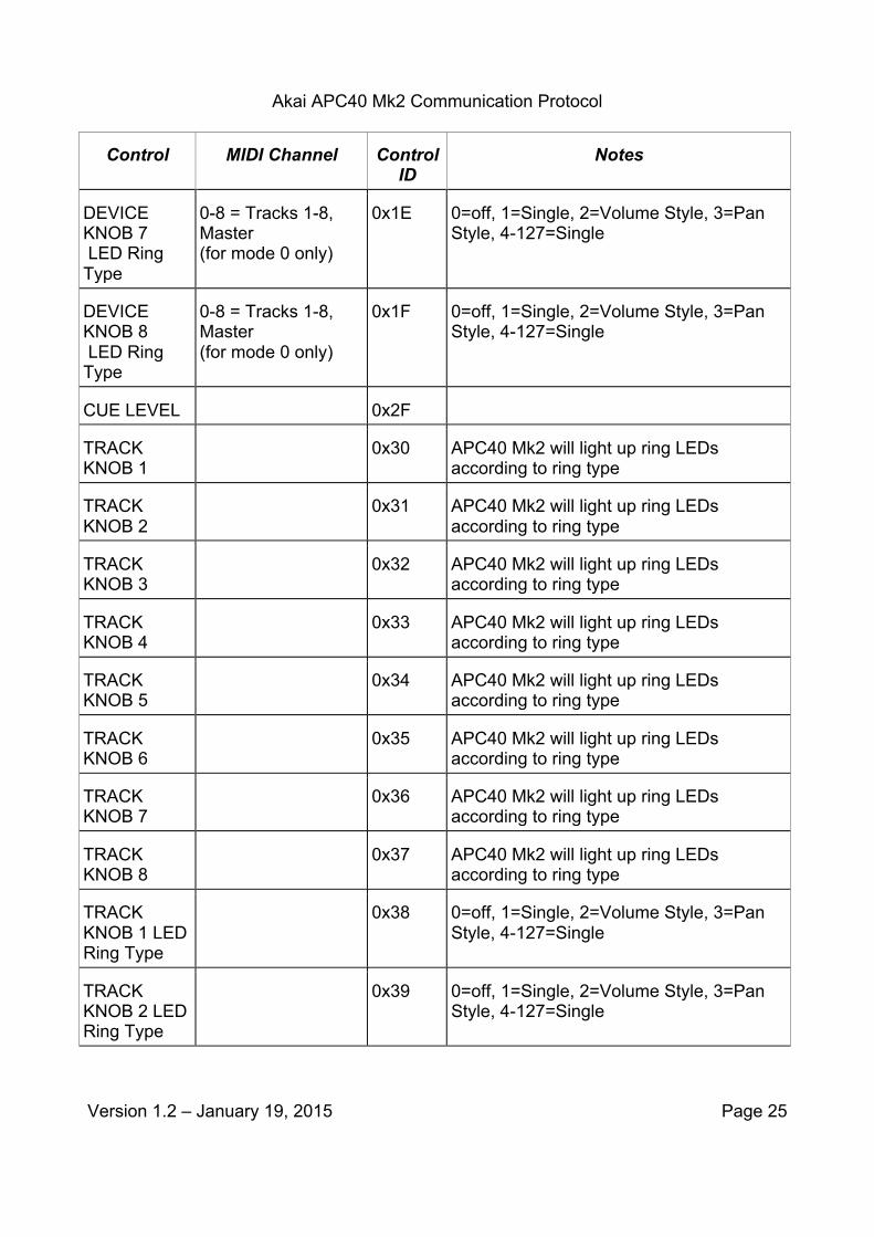
Outbound Message Type 2: Controller Value Update messages Controls that report an absolute value for their position for inbound messages can have their controller value updated via a Controller Value Update message. This will be done using a MIDI controller message. The field normally associated with controller number will be used to specify the Control ID. The field normally associated with controller value will be used to update the value of a controller on the APC40 Mk2.

Akai APC40 Mk2 Communication Protocol
Version 1.2 – January 19, 2015 Page 23
MIDI Controller message
Byte Number
Value Description
1 0xB<chan>
MIDI Controller. The 4-bit <chan> value will be used for the track strips
2 <ControlID>
Identifier for control surface object
3 Data Control value Assignment of controller numbers to absolute controllers
Control MIDI Channel Control ID
Notes
TRACK FADER
0-7 = Tracks 1-8 0x07
TEMPO KNOB
0x0D
MASTER FADER
0x0E
CROSSFADER
0x0F
DEVICE KNOB 1
0-8 = Tracks 1-8, Master (for mode 0 only)
0x10 See “Interpretation of LED Ring Types”
DEVICE KNOB 2
0-8 = Tracks 1-8, Master (for mode 0 only)
0x11 See “Interpretation of LED Ring Types”
DEVICE KNOB 3
0-8 = Tracks 1-8, Master (for mode 0 only)
0x12 See “Interpretation of LED Ring Types”
DEVICE KNOB 4
0-8 = Tracks 1-8, Master (for mode 0 only)
0x13 See “Interpretation of LED Ring Types”
DEVICE 0-8 = Tracks 1-8, 0x14 See “Interpretation of LED Ring Types”

Akai APC40 Mk2 Communication Protocol
Version 1.2 – January 19, 2015 Page 24
Control MIDI Channel Control ID
Notes
KNOB 5 Master (for mode 0 only)
DEVICE KNOB 6
0-8 = Tracks 1-8, Master (for mode 0 only)
0x15 See “Interpretation of LED Ring Types”
DEVICE KNOB 7
0-8 = Tracks 1-8, Master (for mode 0 only)
0x16 See “Interpretation of LED Ring Types”
DEVICE KNOB 8
0-8 = Tracks 1-8, Master (for mode 0 only)
0x17 See “Interpretation of LED Ring Types”
DEVICE KNOB 1 LED Ring Type
0-8 = Tracks 1-8, Master (for mode 0 only)
0x18 0=off, 1=Single, 2=Volume Style, 3=Pan Style, 4-127=Single
DEVICE KNOB 2 LED Ring Type
0-8 = Tracks 1-8, Master (for mode 0 only)
0x19 0=off, 1=Single, 2=Volume Style, 3=Pan Style, 4-127=Single
DEVICE KNOB 3 LED Ring Type
0-8 = Tracks 1-8, Master (for mode 0 only)
0x1A 0=off, 1=Single, 2=Volume Style, 3=Pan Style, 4-127=Single
DEVICE KNOB 4 LED Ring Type
0-8 = Tracks 1-8, Master (for mode 0 only)
0x1B 0=off, 1=Single, 2=Volume Style, 3=Pan Style, 4-127=Single
DEVICE KNOB 5 LED Ring Type
0-8 = Tracks 1-8, Master (for mode 0 only)
0x1C 0=off, 1=Single, 2=Volume Style, 3=Pan Style, 4-127=Single
DEVICE KNOB 6 LED Ring Type
0-8 = Tracks 1-8, Master (for mode 0 only)
0x1D 0=off, 1=Single, 2=Volume Style, 3=Pan Style, 4-127=Single
Akai APC40 Mk2 Communication Protocol
Version 1.2 – January 19, 2015 Page 25
Control MIDI Channel Control ID
Notes
DEVICE KNOB 7 LED Ring Type
0-8 = Tracks 1-8, Master (for mode 0 only)
0x1E 0=off, 1=Single, 2=Volume Style, 3=Pan Style, 4-127=Single
DEVICE KNOB 8 LED Ring Type
0-8 = Tracks 1-8, Master (for mode 0 only)
0x1F 0=off, 1=Single, 2=Volume Style, 3=Pan Style, 4-127=Single
CUE LEVEL 0x2F
TRACK KNOB 1
0x30 APC40 Mk2 will light up ring LEDs according to ring type
TRACK KNOB 2
0x31 APC40 Mk2 will light up ring LEDs according to ring type
TRACK KNOB 3
0x32 APC40 Mk2 will light up ring LEDs according to ring type
TRACK KNOB 4
0x33 APC40 Mk2 will light up ring LEDs according to ring type
TRACK KNOB 5
0x34 APC40 Mk2 will light up ring LEDs according to ring type
TRACK KNOB 6
0x35 APC40 Mk2 will light up ring LEDs according to ring type
TRACK KNOB 7
0x36 APC40 Mk2 will light up ring LEDs according to ring type
TRACK KNOB 8
0x37 APC40 Mk2 will light up ring LEDs according to ring type
TRACK KNOB 1 LED Ring Type
0x38 0=off, 1=Single, 2=Volume Style, 3=Pan Style, 4-127=Single
TRACK KNOB 2 LED Ring Type
0x39 0=off, 1=Single, 2=Volume Style, 3=Pan Style, 4-127=Single

Akai APC40 Mk2 Communication Protocol
Version 1.2 – January 19, 2015 Page 26
Control MIDI Channel Control ID
Notes
TRACK KNOB 3 LED Ring Type
0x3A 0=off, 1=Single, 2=Volume Style, 3=Pan Style, 4-127=Single
TRACK KNOB 4 LED Ring Type
0x3B 0=off, 1=Single, 2=Volume Style, 3=Pan Style, 4-127=Single
TRACK KNOB 5 LED Ring Type
0x3C 0=off, 1=Single, 2=Volume Style, 3=Pan Style, 4-127=Single
TRACK KNOB 6 LED Ring Type
0x3D 0=off, 1=Single, 2=Volume Style, 3=Pan Style, 4-127=Single
TRACK KNOB 7 LED Ring Type
0x3E 0=off, 1=Single, 2=Volume Style, 3=Pan Style, 4-127=Single
TRACK KNOB 8 LED Ring Type
0x3F 0=off, 1=Single, 2=Volume Style, 3=Pan Style, 4-127=Single
Footswitch 0x40
Interpretation of LED Ring Types The LED rings will display its controller value with the LEDs based on the LED Ring Types. This LED Ring Type can be set by the Host by sending an appropriate controller value message. The “Min” and “Max” columns below will state the range of the controller value that will match the LED states as shown in the “Display” column. The “LED STATES” column below will show the state of each of the 15 LEDs going from left to right. A “0” indicates that the LED within the LED ring is OFF. A “1” indicates that the LED within the LED ring in ON.
A. SINGLE
MIN MAX LED STATES 0 3 100000000000000

Akai APC40 Mk2 Communication Protocol
Version 1.2 – January 19, 2015 Page 27
MIN MAX LED STATES 4 8 110000000000000
9 12 010000000000000 13 17 011000000000000
18 21 001000000000000 22 25 001100000000000
26 30 000100000000000
31 34 000110000000000 35 38 000010000000000
39 43 000011000000000 44 47 000001000000000
48 52 000001100000000 53 56 000000100000000
57 60 000000110000000 61 65 000000010000000
66 69 000000011000000 70 73 000000001000000
74 78 000000001100000 79 82 000000000100000
83 87 000000000110000 88 91 000000000010000
92 95 000000000011000
96 100 000000000001000 101 104 000000000001100
105 108 000000000000100 109 113 000000000000110
114 117 000000000000010 118 122 000000000000011
123 127 000000000000001
B. VOLUME STYLE

Akai APC40 Mk2 Communication Protocol
Version 1.2 – January 19, 2015 Page 28
MIN MAX LED STATES
0 0 000000000000000
1 9 100000000000000
10 18 110000000000000
19 27 111000000000000
28 36 111100000000000
37 45 111110000000000
46 54 111111000000000
55 63 111111100000000
64 71 111111110000000
72 80 111111111000000
81 89 111111111100000
90 98 111111111110000
99 107 111111111111000
108 116 111111111111100
117 126 111111111111110
127 127 111111111111111
C. PAN STYLE
MIN MAX LED STATES
0 8 111111110000000
9 17 011111110000000
18 26 001111110000000

Akai APC40 Mk2 Communication Protocol
Version 1.2 – January 19, 2015 Page 29
MIN MAX LED STATES
27 35 000111110000000
36 44 000011110000000
45 53 000001110000000
54 62 000000110000000
63 64 000000010000000
65 73 000000011000000
74 82 000000011100000
83 91 000000011110000
92 100 000000011111000
101 109 000000011111100
110 118 000000011111110
119 127 000000011111111
Communications from device to PC Host - “Inbound” messages These messages will be used to report control surface events from the device to the PC Host and as a response to requests from the PC host.
Inbound Standard MIDI Message types These messages will use standard MIDI messages. Each message type will contain a Control Identifier field, which will identify the control surface object to which the message pertains. Each message type will contain a data field, which may contain information about either the new value of the control surface object or how it has changed since the last report.
Type NOTE1: Note-on/Note-off messages Some devices (such as buttons) have two states and the transitions between these states will be reported using MIDI note-on (when the button is depressed) and note-off (when the button is released). The field normally associated with note number will be used to specify

Akai APC40 Mk2 Communication Protocol
Version 1.2 – January 19, 2015 Page 30
the Control ID.
Midi note-on messages
Byte Number
Value Description
1 0x9<chan>
MIDI Note-on. The 4-bit <chan> value will be used for the track strips.
2 <ControlID>
Identifier for control surface object (“note number”)
3 0x7F Control value (non-zero)
Midi note-off messages
Byte Number
Value Description
1 0x8<chan>
MIDI Note-off. The 4-bit <chan> value will be used for the track strips
2 <ControlID>
Identifier for control surface object (“note number”)
3 0x7F Control value (ignored)
Assignment of note numbers to buttons. Note 0x30 to 0x49 use MIDI Channel 0 to 7 to indicate Tracks 1-8. All other note values ignore the MIDI Channel. In Mode 1 or Mode 2, all buttons act as momentary buttons.
Control MIDI Channel Note Number
CLIP LAUNCH 1 0x00
CLIP LAUNCH 2 0x01
CLIP LAUNCH 3 0x02
CLIP LAUNCH 4 0x03
CLIP LAUNCH 5 0x04
CLIP LAUNCH 6 0x05

Akai APC40 Mk2 Communication Protocol
Version 1.2 – January 19, 2015 Page 31
CLIP LAUNCH 7 0x06
CLIP LAUNCH 8 0x07
CLIP LAUNCH 9 0x08
CLIP LAUNCH 10 0x09
CLIP LAUNCH 11 0x0A
CLIP LAUNCH 12 0x0B
CLIP LAUNCH 13 0x0C
CLIP LAUNCH 14 0x0D
CLIP LAUNCH 15 0x0E
CLIP LAUNCH 16 0x0F
CLIP LAUNCH 17 0x10
CLIP LAUNCH 18 0x11
CLIP LAUNCH 19 0x12
CLIP LAUNCH 20 0x13
CLIP LAUNCH 21 0x14
CLIP LAUNCH 22 0x15
CLIP LAUNCH 23 0x16
CLIP LAUNCH 24 0x17
CLIP LAUNCH 25 0x18
CLIP LAUNCH 26 0x19
CLIP LAUNCH 27 0x1A
CLIP LAUNCH 28 0x1B
CLIP LAUNCH 29 0x1C
CLIP LAUNCH 30 0x1D
CLIP LAUNCH 31 0x1E

Akai APC40 Mk2 Communication Protocol
Version 1.2 – January 19, 2015 Page 32
CLIP LAUNCH 32 0x1F
CLIP LAUNCH 33 0x20
CLIP LAUNCH 34 0x21
CLIP LAUNCH 35 0x22
CLIP LAUNCH 36 0x23
CLIP LAUNCH 37 0x24
CLIP LAUNCH 38 0x25
CLIP LAUNCH 39 0x26
CLIP LAUNCH 40 0x27
RECORD ARM 0x30 (C_3)
SOLO 0x31 (C#3)
ACTIVATOR 0x32 (D_3)
TRACK SELECTION
0x33 (D#3)
TRACK STOP 0x34 (E_3)
DEVICE LEFT 0x3A
DEVICE RIGHT 0x3B
BANK LEFT 0x3C
BANK RIGHT 0x3D
DEVICE ON/OFF 0x3E
DEVICE LOCK 0x3F
CLIP/DEVICE VIEW
0x40
DETAIL VIEW 0x41
CROSSFADER A/B
0x42

Akai APC40 Mk2 Communication Protocol
Version 1.2 – January 19, 2015 Page 33
CLIP STOP 0-7 = Track 1-8
MASTER 0x50 (G#5)
STOP ALL CLIPS 0x51 (A_5)
SCENE LAUNCH 1
0x52 (A#5)
SCENE LAUNCH 2
0x53 (B_5)
SCENE LAUNCH 3
0x54 (C_6)
SCENE LAUNCH 4
0x55 (C#6)
SCENE LAUNCH 5
0x56 (D_6)
METRONOME (8)
0-8 = Tracks 1-8, Master (for mode 0 only)
0x41 (F_4)
PAN 0x57 (D#6)
SENDS 0x58 (E_6)
USER 0x59 (F_6)
METRONOME 0x5A (F#6)
PLAY 0x5B (G_6)
STOP 0x5C
(G#6)
RECORD 0x5D (A_6)
UP 0x5E (A#6)
DOWN 0x5F (B_6)
RIGHT 0x60 (C_7)
LEFT 0x61 (C#7)

Akai APC40 Mk2 Communication Protocol
Version 1.2 – January 19, 2015 Page 34
SHIFT 0x62 (D_7)
TAP TEMPO 0x63 (D#7)
NUDGE - 0x64 (E_7)
NUDGE + 0x65 (F_7)
SESSION RECORD
0x66
BANK LOCK 0x67
Type CC1: Absolute Controller messages Most controls will report an absolute value for their position. This will be done using a MIDI controller message. The field normally associated with controller number will be used to specify the Control ID. The field normally associated with controller value will be used to report the absolute control value.
MIDI Controller message
Byte number Value Description
1 0xB<chan> MIDI Controller. The 4-bit <chan> value will be used for the track.
2 <ControlID> identifier for control surface object
3 data control value
Assignment of controller numbers to absolute controllers
Control MIDI Channel Control ID Notes
TRACK FADER 0-7 = Tracks 1-8 0x07
MASTER FADER 0x0E
CROSSFADER 0x0F
DEVICE KNOB 1 0-8 = Tracks 1-8, Master (for Mode 0 only)
0x10
DEVICE KNOB 2 0-8 = Tracks 1-8, Master 0x11

Akai APC40 Mk2 Communication Protocol
Version 1.2 – January 19, 2015 Page 35
Control MIDI Channel Control ID Notes (for Mode 0 only)
DEVICE KNOB 3 0-8 = Tracks 1-8, Master (for Mode 0 only)
0x12
DEVICE KNOB 4 0-8 = Tracks 1-8, Master (for Mode 0 only)
0x13
DEVICE KNOB 5 0-8 = Tracks 1-8, Master (for Mode 0 only)
0x14
DEVICE KNOB 6 0-8 = Tracks 1-8, Master (for Mode 0 only)
0x15
DEVICE KNOB 7 0-8 = Tracks 1-8, Master (for Mode 0 only)
0x16
DEVICE KNOB 8 0-8 = Tracks 1-8, Master (for Mode 0 only)
0x17
DEVICE KNOB 1
0-8 = Tracks 1-8, Master (for mode 0 only)
0x18
DEVICE KNOB 2
0-8 = Tracks 1-8, Master (for mode 0 only)
0x19
DEVICE KNOB 3
0-8 = Tracks 1-8, Master (for mode 0 only)
0x1A
DEVICE KNOB 4
0-8 = Tracks 1-8, Master (for mode 0 only)
0x1B
DEVICE KNOB 5
0-8 = Tracks 1-8, Master (for mode 0 only)
0x1C
DEVICE KNOB 6
0-8 = Tracks 1-8, Master (for mode 0 only)
0x1D
DEVICE KNOB 7
0-8 = Tracks 1-8, Master (for mode 0 only)
0x1E
DEVICE KNOB 8
0-8 = Tracks 1-8, Master (for mode 0 only)
0x1F
CUE LEVEL 0x2F

Akai APC40 Mk2 Communication Protocol
Version 1.2 – January 19, 2015 Page 36
Control MIDI Channel Control ID Notes
TRACK KNOB 1 0x30
TRACK KNOB 2 0x31
TRACK KNOB 3 0x32
TRACK KNOB 4 0x33
TRACK KNOB 5 0x34
TRACK KNOB 6 0x35
TRACK KNOB 7 0x36
TRACK KNOB 8 0x37
TRACK KNOB 1 0x38
TRACK KNOB 2 0x39
TRACK KNOB 3 0x3A
TRACK KNOB 4 0x3B
TRACK KNOB 5 0x3C
TRACK KNOB 6 0x3D
TRACK KNOB 7 0x3E
TRACK KNOB 8 0x3F
Footswitch 0x40 Value of 0x7F when depressed and a value of 0x00 when released
Type CC2: Relative Controller messages Some controls will report a relative change in their value. This will be done using a MIDI controller message. The field normally associated with controller number will be used to specify the Control ID. The field normally associated with controller value will be used to report the change in the control value.

Akai APC40 Mk2 Communication Protocol
Version 1.2 – January 19, 2015 Page 37
MIDI Controller message
Byte Number
Value Description
1 0xB<chan> MIDI Controller. The 4-bit <chan> value will be used for the track strips
2 <ControlID> identifier for control surface object
3 data control change
Interpretation of MIDI Controller values for Relative Controllers
The value in the data field will indicate a relative change; values 01 to 63 describe a positive change and values 127 down to 64 describe a negative change.
Data Value Sent Interpretation
0x00 No change occurred. Control is stationary.
0x01 The controller incremented its value by 1 since the last report
0x02 The controller incremented its value by 2 since the last report
... ...
0x3f The controller incremented its value by 63 since the last report
0x40 The controller decremented its value by 64 since the last report
0x41 The controller decremented its value by 63 since the last report
... ...
0x7e The controller decremented its value by 2 since the last report
0x7f The controller decremented its value by 1 since the last report Assignment of controller numbers to relative controllers
Control Control ID Notes
CUE LEVEL 0x2F
TEMPO KNOB 0x0D

Akai APC40 Mk2 Communication Protocol
Version 1.2 – January 19, 2015 Page 38
Document History
Date Author
January 7, 2015 First Draft based on APC40 Communications Protocol document
Kris Stevenson
January 8, 2015 Revisions made to 1st draft after review with Eng.
Kris Stevenson
January 19, 2015 Tempo Knob removed from Absolute Controller Messages table on p36 and added to Relative Controller Messages table on p39.
Kris Stevenson
January 19, 2015 Added Track Activator, Crossfader A/B, Track Solo, Track Record, Bank, Play, Record, Session Record, Pan, Sends, User, and Metronome button types to Outbound Message Type: Generic Mode on p12-13.
Kris Stevenson
Recommended