Analytical Methods for Materials
Lesson 5The Optical Microscope and Imaging Modes
Suggested Reading•Y. Leng, Materials Characterization, 2nd Edition, (2013), Wiley, Hoboken, NJ – Chapter 1.
Reference•Goodhew, Humphreys and Beanland, Chapter 1•Brandon and Kaplan, Chapter 3, pp. 123-177•K. Geels, D.B. Fowler, W-U. Kopp, and M. Rückert, Metallographic and Materialographic Specimen Preparation, Light Microscopy, Image Analysis and Hardness Testing, (2007) ASTM International, West Conshohocken, PA.•G.F. Vander Voort, Metallography Principles and Practice, (1999) ASM International, Materials Park, OH. 107
Introduction• Differences in properties of light reflected from a
specimen allow us to identify microstructural features.
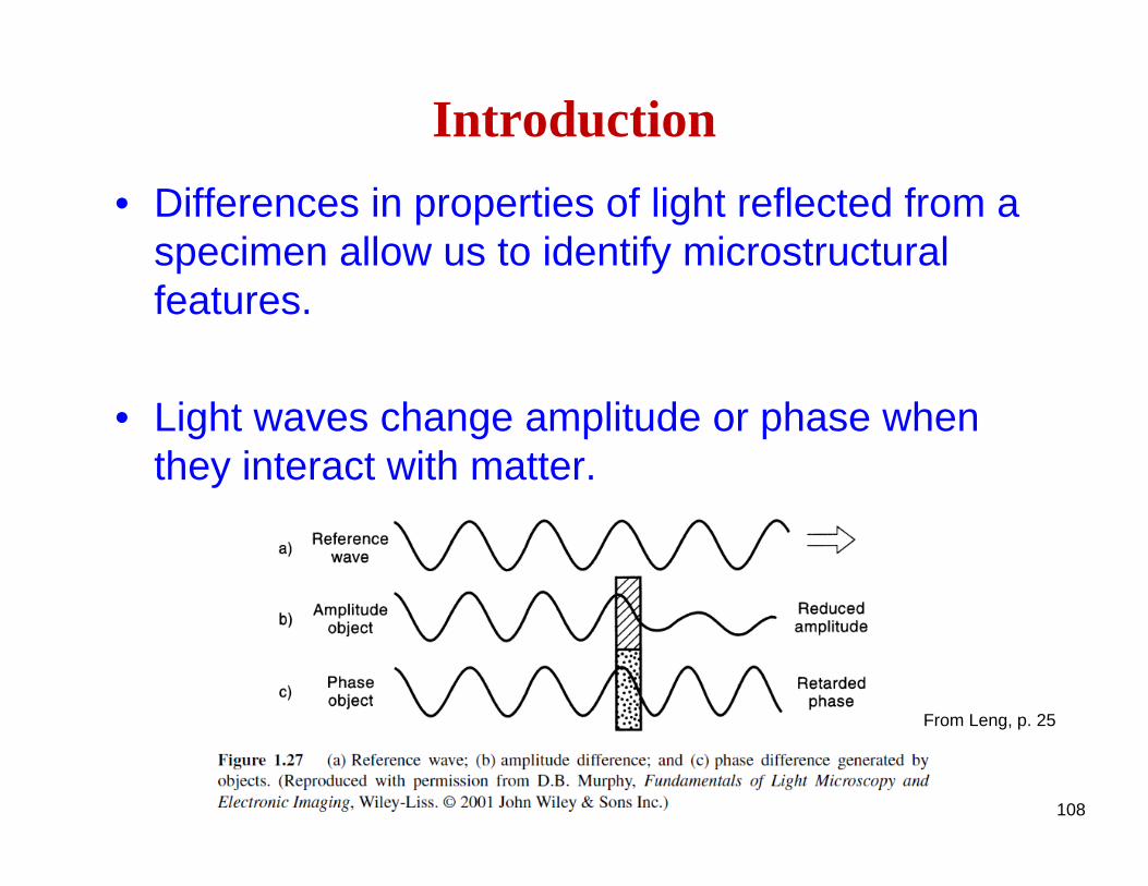
• Light waves change amplitude or phase when they interact with matter.
108
From Leng, p. 25
Introduction
• The eye can only distinguish differences in amplitude and wavelength.– Bright-field imaging– Dark-field imaging
• Phase differences must be converted into amplitude differences.– Phase contrast imaging– Polarized light imaging– Nomarski contrast
109
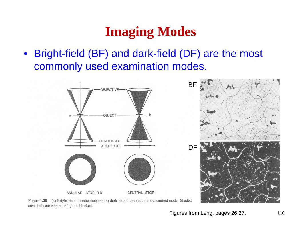
Imaging Modes• Bright-field (BF) and dark-field (DF) are the most
commonly used examination modes.
110
BF
DF
Figures from Leng, pages 26,27.
111
Examination ModesBright Field
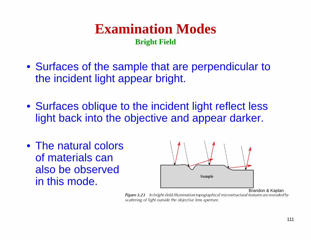
• Surfaces of the sample that are perpendicular to the incident light appear bright.
• Surfaces oblique to the incident light reflect less light back into the objective and appear darker.
• The natural colorsof materials can also be observed in this mode.
Brandon & Kaplan
112
Examination ModesDark Field
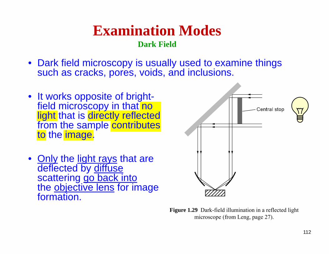
Figure 1.29 Dark-field illumination in a reflected light microscope (from Leng, page 27).
• Dark field microscopy is usually used to examine things such as cracks, pores, voids, and inclusions.
• It works opposite of bright-field microscopy in that no light that is directly reflected from the sample contributes to the image.
• Only the light rays that are deflected by diffusescattering go back intothe objective lens for image formation.
113
Examination ModesPhase Contrast
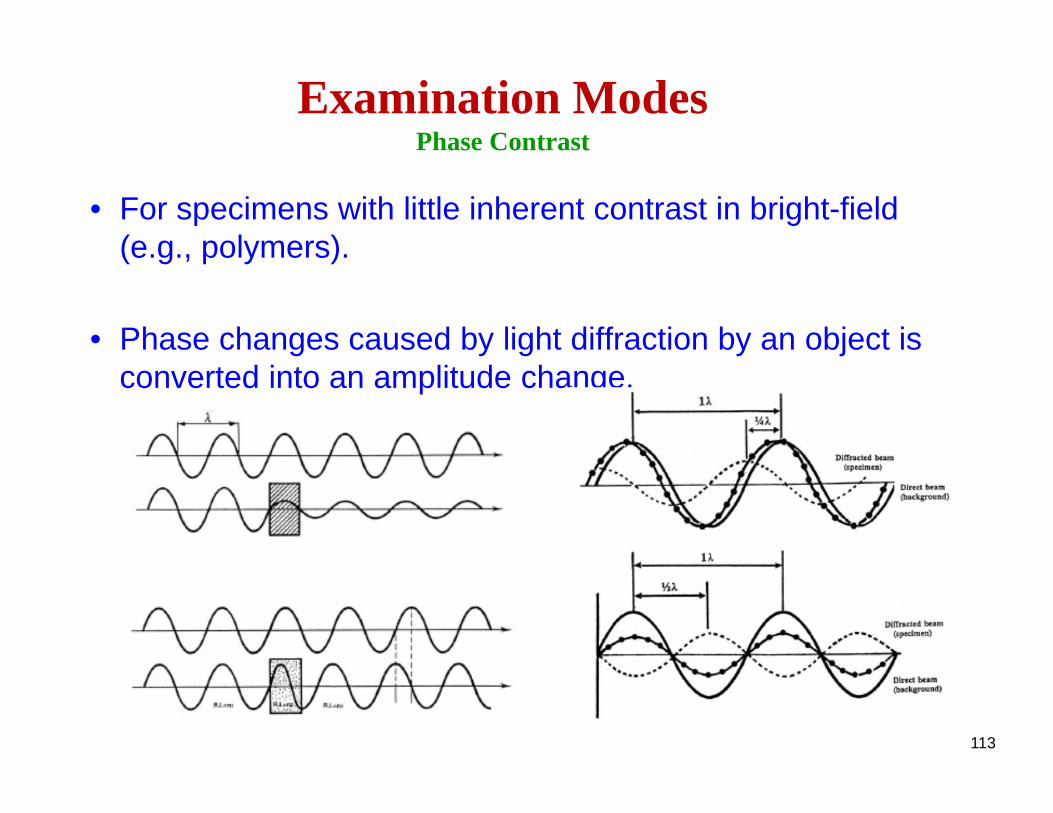
• For specimens with little inherent contrast in bright-field (e.g., polymers).
• Phase changes caused by light diffraction by an object is converted into an amplitude change.
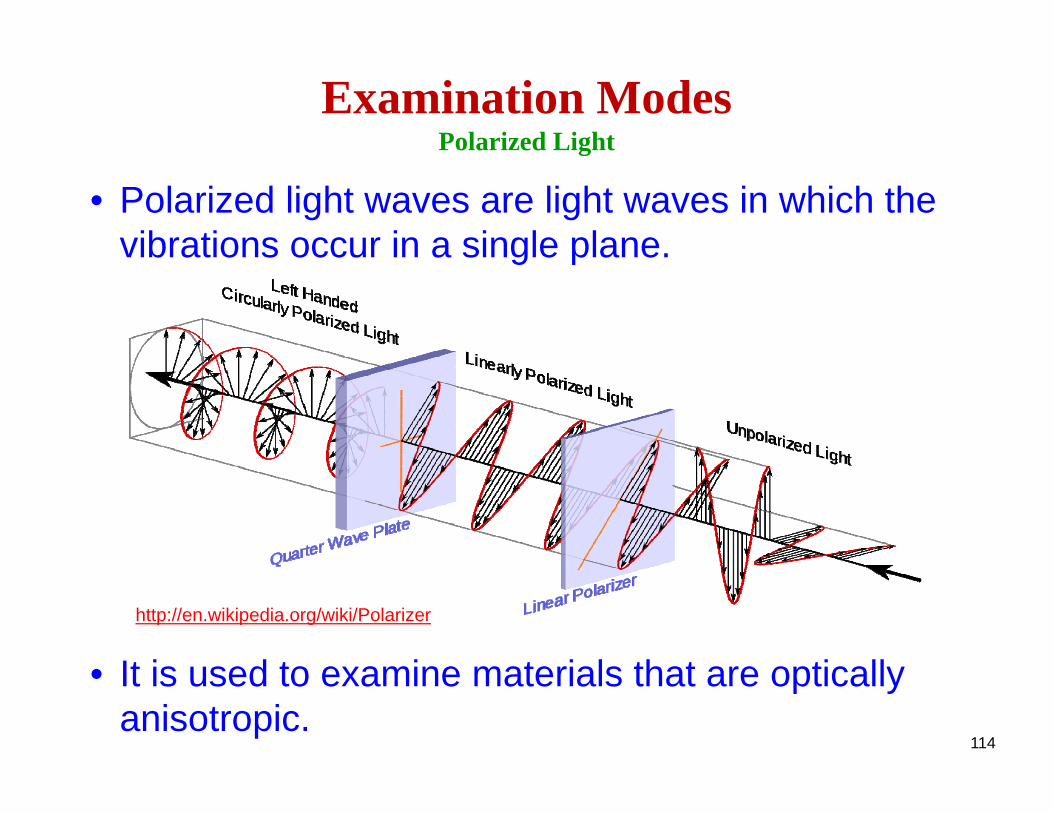
• Polarized light waves are light waves in which the vibrations occur in a single plane.
• It is used to examine materials that are optically anisotropic.
114
Examination ModesPolarized Light
http://en.wikipedia.org/wiki/Polarizer
115
Examination ModesPolarized Light
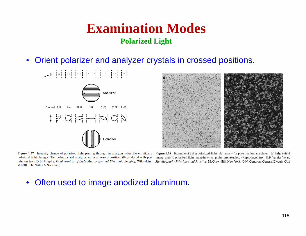
• Orient polarizer and analyzer crystals in crossed positions.
• Often used to image anodized aluminum.
116
Examination ModesDifferential Interference Contrast (DIC)
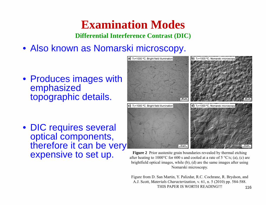
• Also known as Nomarski microscopy.
• Produces images with emphasized topographic details.
• DIC requires several optical components, therefore it can be very expensive to set up. Figure 2 Prior austenite grain boundaries revealed by thermal etching
after heating to 1000°C for 600 s and cooled at a rate of 5 °C/s; (a), (c) are brightfield optical images, while (b), (d) are the same images after using
Nomarski microscopy.
Figure from D. San Martin, Y. Palizdar, R.C. Cochrane, R. Brydson, and A.J. Scott, Materials Characterization, v. 61, n. 5 (2010) pp. 584-588.
THIS PAPER IS WORTH READING!!!

117
Examination ModesDifferential Interference Contrast (DIC)
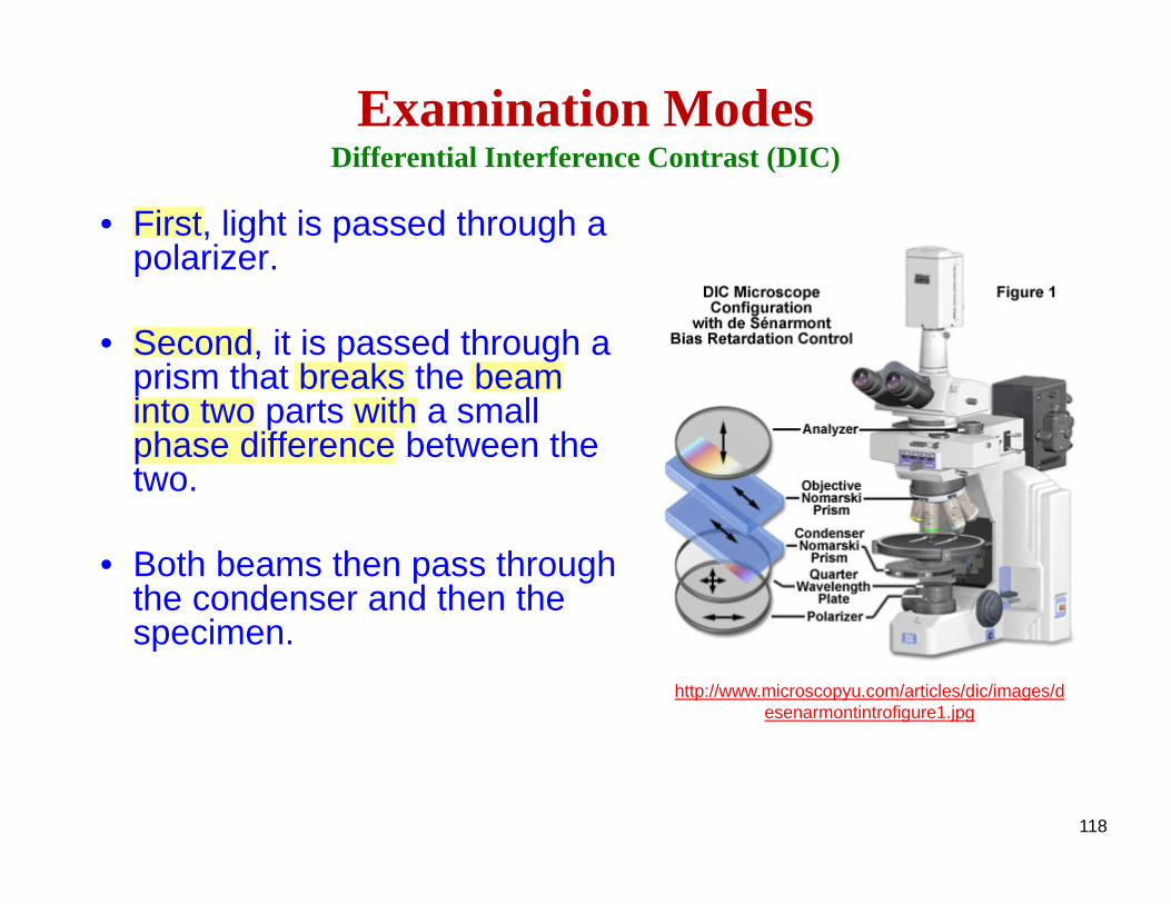
• First, light is passed through a polarizer.
• Second, it is passed through a prism that breaks the beam into two parts with a small phase difference between the two.
• Both beams then pass through the condenser and then the specimen.
http://www.microscopyu.com/articles/dic/images/desenarmontintrofigure1.jpg
118
Examination ModesDifferential Interference Contrast (DIC)
• First, light is passed through a polarizer.
• Second, it is passed through a prism that breaks the beam into two parts with a small phase difference between the two.
• Both beams then pass through the condenser and then the specimen.
http://www.microscopyu.com/articles/dic/images/desenarmontintrofigure1.jpg
119
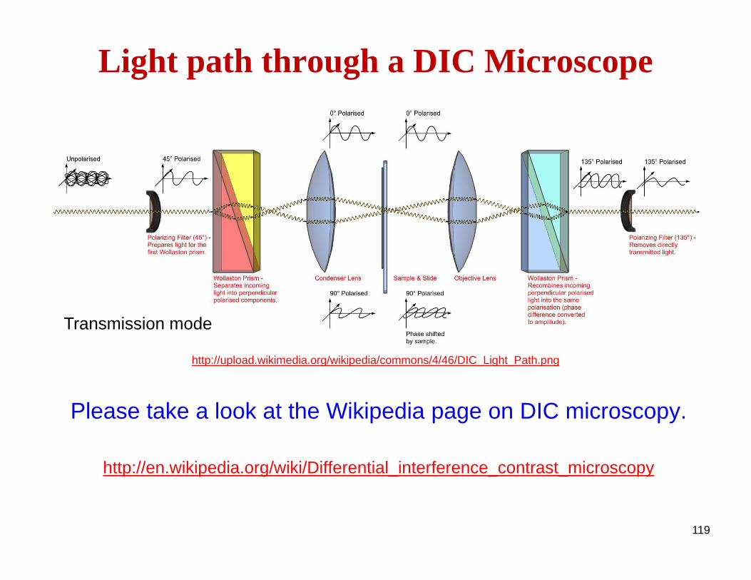
http://upload.wikimedia.org/wikipedia/commons/4/46/DIC_Light_Path.png
Please take a look at the Wikipedia page on DIC microscopy.
http://en.wikipedia.org/wiki/Differential_interference_contrast_microscopy
Light path through a DIC Microscope
Transmission mode
120
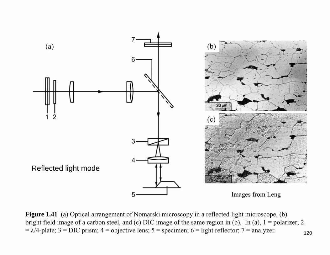
Figure 1.41 (a) Optical arrangement of Nomarski microscopy in a reflected light microscope, (b) bright field image of a carbon steel, and (c) DIC image of the same region in (b). In (a), 1 = polarizer; 2 = λ/4-plate; 3 = DIC prism; 4 = objective lens; 5 = specimen; 6 = light reflector; 7 = analyzer.
(a) (b)
(c)
Reflected light mode
Images from Leng
121
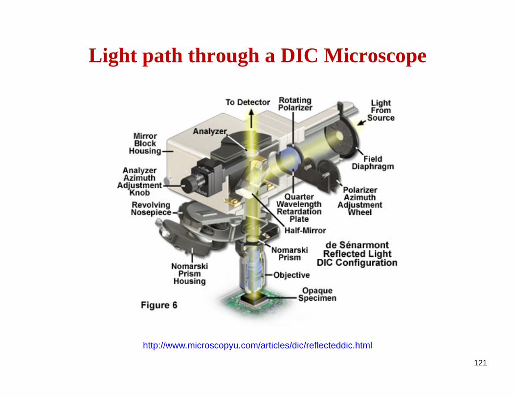
Light path through a DIC Microscope
http://www.microscopyu.com/articles/dic/reflecteddic.html
122
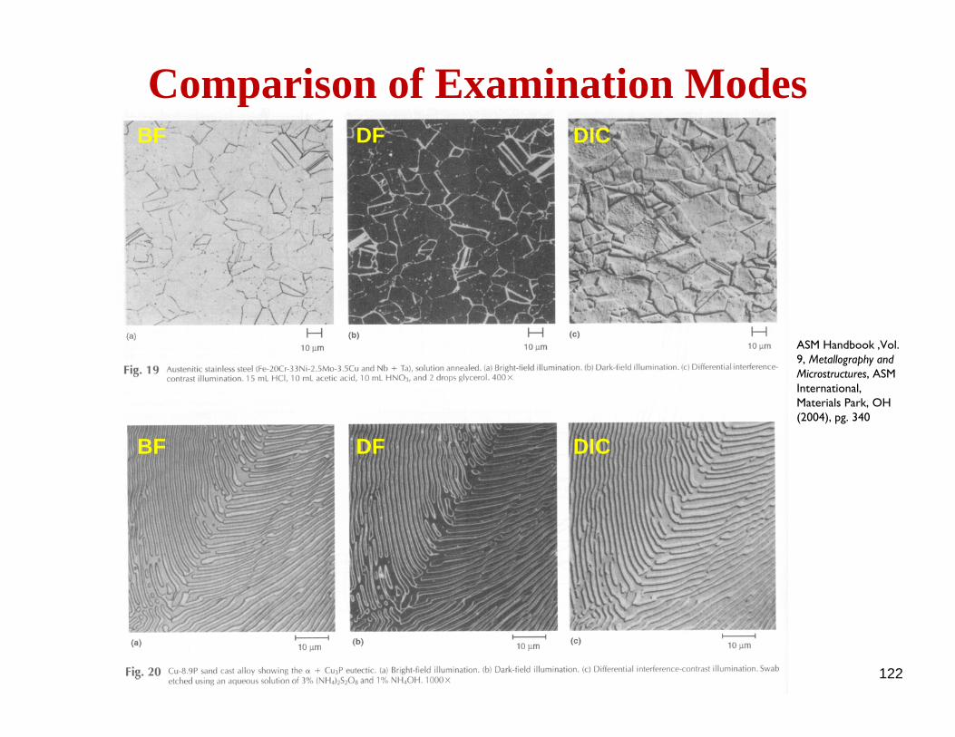
Comparison of Examination Modes
ASM Handbook ,Vol. 9, Metallography and Microstructures, ASM International, Materials Park, OH (2004), pg. 340
BF DF DIC
BF DF DIC
Recommended