International Journal of Research Studies in Electrical and Electronics Engineering (IJRSEEE)
Volume 3, Issue 3, 2017, PP 15-32
ISSN 2454-9436 (Online)
DOI: http://dx.doi.org/10.20431/2454-9436.0303003
www.arcjournals.org
International Journal of Research Studies in Electrical and Electronics Engineering (IJRSEEE) Page | 15
An Overview of Power Electronics Techniques in Electric Systems
for Transport Applications
Kai Ni, Yihua Hu, Joseph Yan, and Hui Xu
Department of Electrical Engineering and Electronics,
The University of Liverpool, Liverpool, UK
1. INTRODUCTION
At present, the airplane, ship and vehicle are the three main types of transport tools, and increasing
use of these tools can be observed all over the world, since mobility is one of the most important
parameters for achieving economic development. However, according to [1], one third of the total
greenhouse gas (GHG) emissions are generated from the transportation system. In order to achieve the
ultimate aim of sustainable development, more environmentally friendly means for transportation
should be developed. In address to the three forms of transportation mentioned above, the concepts of
more-electric aircrafts (MEAs)[2], electric ships (ESs) [3] and electric vehicles (EVs) [4] were
proposed, and electric propulsion systems are used to in these applications to replace the original ones
based on conventional energy resources for carbon emission reduction.
For MEA, the subsystems utilizing hydraulic, mechanical, and pneumatic power that were previously
used in conventional airplanes are replaced by electrical systems. The pneumatic power is used to
produce bleed air for the Environmental Control System (ECS) to make the passengers feel
comfortable as it is used for pressurization and air-conditioning purposes. In addition, it also plays an
important role in de-icing for the wings of an airplane. In terms of the mechanical power, it is
transferred from the engines to different kinds of mechanically driven hydraulic pumps, generators
and subsystems by using the gearboxes [5]. High power density and robustness are obtained for the
hydraulic power subsystems, while they are heavy and inflexible [5]. In the relatively new types of
airplanes such as the Boeing 787 and Airbus A380, increased use of electrical power systems is
realized, which is beneficial for mitigating CO2 emissions all over the world. With the utilization of
MEA concept, all the on-board loads are required to take power from an electrical system [6, 7].
Therefore, the overall weight can be reduced since the mechanical and hydraulic systems are
removed. In addition, owing to the elimination of the pneumatic system, the efficiency of the turbine
Abstract: This paper presents an overview of power electronics techniques used in electric systems for
transport applications, including more-electric aircraft (MEA), electric ship (ES), and electric vehicle (EV).
As the worldwide economy is continuously increasing, there is more demand for transportation, which is one
of the most significant sources of carbon emissions. In order to achieve the target of low greenhouse gas
(GHG) emission rate and ultimately realize sustainable development, the concept of using electric systems to
replace the other types of systems that utilize conventional energy resources such as fossil fuels. The
subsystems utilizing hydraulic, mechanical, and pneumatic power that were previously used in conventional
airplanes are replaced by electrical systems in MEA, which reduces the fuel consumption, operating cost, and
noise of aircrafts. Besides, in ES applications, by applying electric propulsion systems, the negative impacts
caused by using long shaft-lines to the propellers can be eliminated since the flexibility of on-board
equipment placement is obtained. Additionally, the concept of EV is becoming popular in the automobile
industry due to the stringent constraints on energy resources and environmental concerns. In order to learn
about the research interests and trends in power electronics techniques for these more- or all-electric
transport applications, a review is carried out in this paper.
Keywords: electric systems, transport applications, more-electric aircraft, electric ship, electric vehicle,
power electronics techniques
*Corresponding Author: Hui Xu, Department of Electrical Engineering and Electronics, The University
of Liverpool, Liverpool, UK
An Overview of Power Electronics Techniques in Electric Systems for Transport Applications
International Journal of Research Studies in Electrical and Electronics Engineering (IJRSEEE) Page | 16
is greatly improved since there is no need for a bleed air system on the gas turbine. As the technology
of MEA develops, minimized mechanical linkages and hydraulic power supply networks are obtained,
which reduces the complexity in maintenance [8].
The history of ES dates back to over a century ago [9, 10], where a limited number of such
applications was presented. Massive production of ESs was not realized until the 1980s, since at that
time the maturity of semiconductor technology was good enough for variable speed control of electric
motors. The electric propulsion system utilizes a number of small units for power generation instead
of a big prime mover, in which case the generator engines are always loaded close to their optimal
operating points [11]. By applying electric propulsion on ships, the placement of equipment on-board
is flexible, which eliminates the negative impacts caused by using long shaft-lines to the propellers.
There are a number of variants for electric propulsion solutions which are dependent on the type of
vessel, operational profiles, and the current available technologies for construction [11]. Three
different application areas of electric propulsion systems for ships were introduced in [11], which are
1) ocean going; 2) station keeping; 3) icebreaking [11]. It was also indicated that the future trends and
technologies for ES involve DC grid, energy storage, hybrid propulsion and dynamic position (DP)
closed bus. Furthermore, future electrical energy sources can be accommodated for ESs, since the
relevant necessary infrastructures are available on-board.
Before the millennium, the concept of EV had occurred, but the modern EV is totally different from
what was defined for the classical one. In this new EV concept, the electric motor, power converter,
and energy sources are involved and distinct characteristics are presented. Moreover, clean and
efficient road transportation is to be accomplished by widely applying the modern EVs [12]. Owing to
the facts that fossil fuels around the world are limited [13], traffic jams in most of the metropolitan
cities are becoming increasingly severe [14], and the procedure of global warming is to be slowed
down or even stopped [15], more stringent constraints on the use of traditional internal combustion
engine (ICE) driven vehicles are presented. Under this circumstance, it is rather urgent to develop
environmentally friendly solutions for transportation. Therefore, the vehicles that utilize partial or full
electric propulsion systems emerge, namely electric vehicles (EVs) [12]. The concept of EV can be
further divided into three categories in general, which are battery electric vehicle (BEV), hybrid
electric vehicle (HEV), and fuel-cell electric vehicle (FCEV) [4, 12].
For the development of these electric systems in applications for transportation, one of the most
critical technologies is power electronics (PE) [16-30]. Since the on-board electric power systems for
MEA, ES and EV are relatively complex, and there are different types of load demands in these
systems, the reasonable control of power flow is important, which is realized by power electronic
devices. In this paper a review is carried out on the applications of PE techniques in MEA, ES and
EV, respectively, which are illustrated in the following three sections (Section II, III and IV). In
Section V, a conclusion will be given.
2. PE TECHNIQUES IN MEA
With the purpose of reducing the fuel consumption, operating cost, and noise of aircrafts, the
emerging concept of ―More-Electric Aircraft‖ (MEA) arises and substantial efforts were made in this
area. The main idea of MEA is replacing the subsystems utilizing hydraulic, mechanical, and
pneumatic power that were previously used in conventional airplanes by electric systems[7]. In a
traditional civil airplane, 115V line-to-neutral ac voltage and a stable line frequency of 400Hz are
applied in the electric power system [2]. While in MEA, usually high voltage direct current (HVDC)
electrical systems are considered. To achieve a lighter weight generator system, 230/400Vac, 400Hz
is a commonly adopted option. Besides, the DC voltage value of 270V on the DC-bus can be utilized,
and therefore a higher voltage of 540Vdc (±270Vdc) can be utilized for the motor controllers [5]. As
an alternative, variable bus frequency between 350 and 800Hz according to the changes in the engine
speed with the voltage regulated at 115 or 230Vac can be adopted, which increases the reliability of
the whole system [31]. Moreover, there are 28Vdc loads on MEA, where the 28V DC voltage is
derived by converting the 115Vac, 400Hz with the application of transformer rectifier units (TRUs)
[32].
Since there are various types of loads (AC and DC) in MEA, and more complex system configuration
is presented, the development of power electronic techniques plays a significant role in the future
aerospace applications. According to [33], the hydraulic systems will be replaced by variable-speed
An Overview of Power Electronics Techniques in Electric Systems for Transport Applications
International Journal of Research Studies in Electrical and Electronics Engineering (IJRSEEE) Page | 17
generators along with power electronics, which are lighter and endowed with a simpler structure. A
comparative evaluation of three-phase AC-DC converters with high power factor was carried out for
future MEA application in [34]. The analysis focused on a passive autotransformer-based 12-pulse
rectifier system and an active three-level boost-type pulse width modulation (PWM) rectifier system.
The most advantageous solution can be derived in the three-level PWM rectifier, and the three-phase
buck plus boost PWM rectifier topology proposed in [35] was demonstrated to have a high system
reliability, since the output capacitor is not required to be charged in advance and load current
limitation for the short circuit case is avoided for startup. In addition, the black-box modelling of
three-phase voltage source inverters (VSIs) was carried out in [36] for system-level analysis in MEA,
where the model is simple, the large-signal behaviour of the converter can be derived, and no internal
data is required for the converter. On top of that, for the purpose of eliminating the harmonics
produced by the on-board nonlinear loads, the design of a fully digitally controlled 400-Hz active
power filter (APF) was presented for aircraft applications in [37].
Multi-level converters are used in some aerospace applications since lower output harmonic
distortions and lower device voltage rating requirement are presented, and they are good candidates
for fault-tolerant ability improvement in MEA systems. The power losses and the harmonic distortion
of the output waveforms were compared for 2-level and 3-level power electronic converters for
aerospace applications in [38], and the superiority of the 3-level topology was demonstrated. As the
increasing use of power electronic subsystems bring several challenges to aircraft power distribution,
a five-level voltage source converter (VSC) was employed in [39] to achieve the high performance
control of harmonic currents along with a modified PWM strategy. In [40] the compensation of load
harmonics in variable-speed constant-frequency (VSCF) aircraft power systems was realized by
designing a five-level cascaded H-bridge active shunt filter. In addition, a 50% reduction in the
converter switching frequency was accomplished by applying a novel modulation technique, which is
based on a phase shift method in [41].
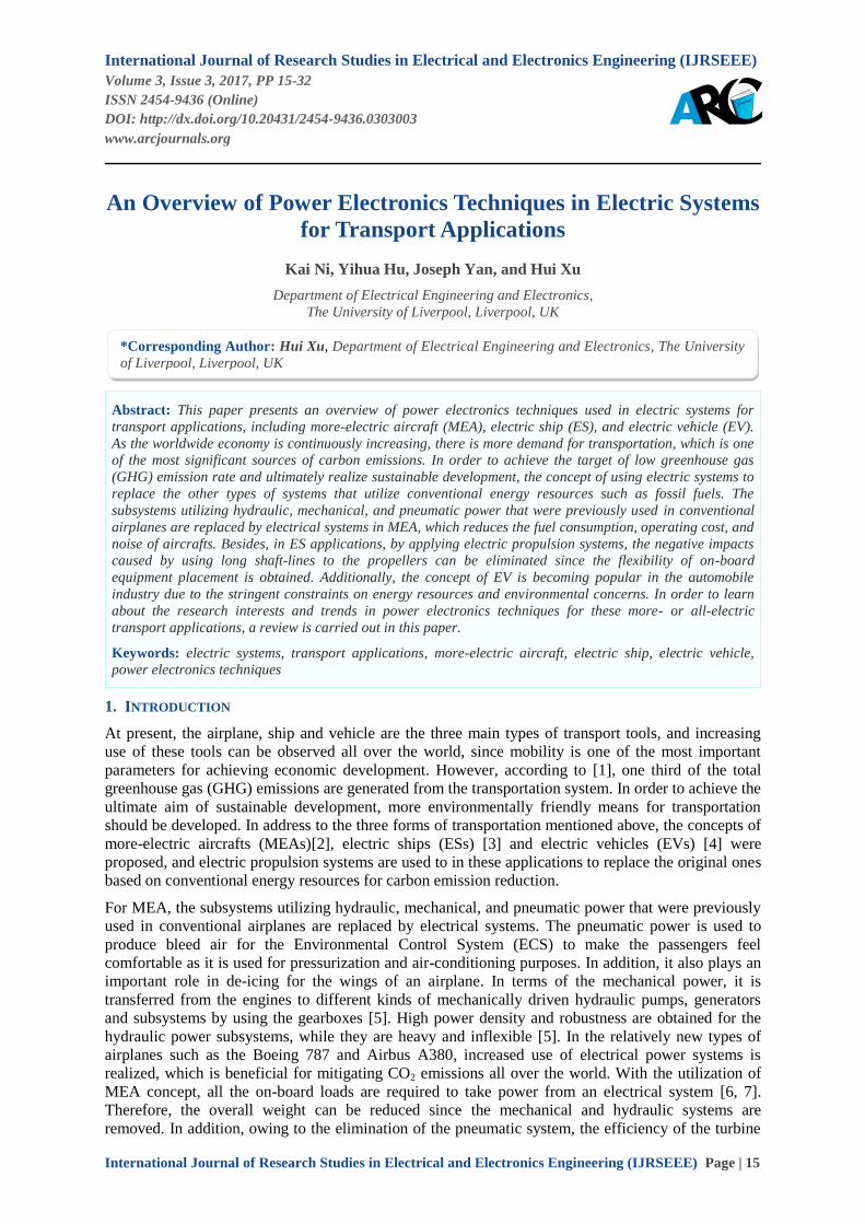
In [42] an experimental tool was introduced for fault-tolerant machine development in aerospace
applications, and a multiphase two-level inverter was presented in the research platform. Data
acquisition, motor control, and fault monitoring were completed by using a field-programmable gate-
array (FPGA)/digital-signal-processor (DSP) controller. In order to make the motor test platform
capable of driving different kinds of machines, the following requirements are presented [42]: 1)
multiphase output; 2) different number of phases can be used to drive various categories of motors; 3)
high-speed controller; PWM generation with high precision; 5) rapid-code-development design cycle.
The schematic of the six-phase motor drive system is illustrated in Fig. 1.
3-Phase Input
Supply
Diode
Bridge
DC-Bus
Capacitors
6-Phase
Inverter
6-Phase
Load
Measurement
Signals
Gate Drive
Signals
Gate Drive Circuits +
Output Current and DC
Link Measurements
Interfaced
FPGA/Gate
Drive
FPGA/DSP
Controller
Power Circuit
Fig1. Six-phase motor drive system [42]
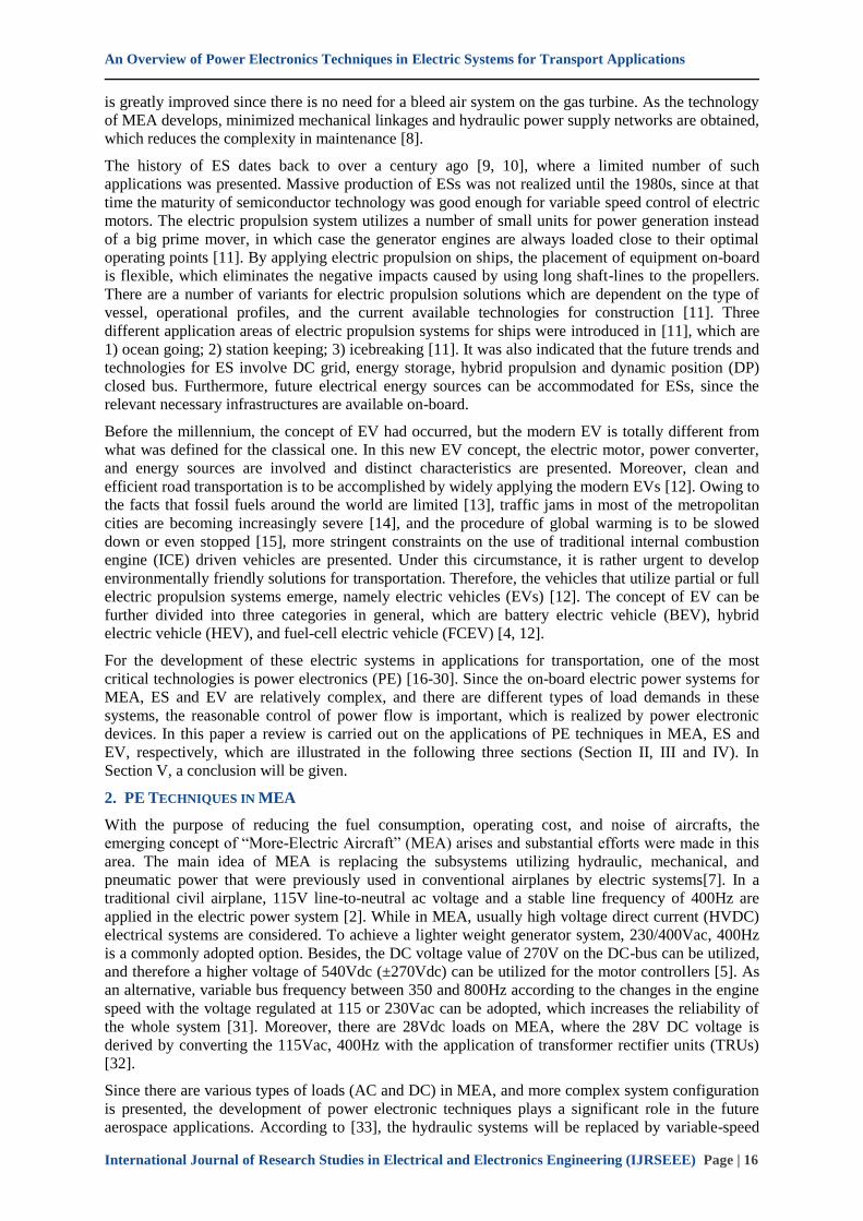
The design of a unidirectional 5-kW three-phase delta-switch rectifier was proposed in paper [43],
which is applicable for the application in aircraft systems with a mains root-mean-square (RMS)
voltage of 115V. The three phases can be controlled at the same time with a novel PWM current
controller modulation concept, and the optimal switching sequences are generated. Single phase loss
can be handled by the proposed three-phase delta-switch topology, and a slightly higher efficiency is
derived compared with a 6-switch Vienna-type rectifier, which is the ideal candidate for the increased
mains voltages of 230VRMS for future airplanes. The equivalent circuit of a two-level three-phase
delta-switch rectifier is displayed in Fig. 2.
An Overview of Power Electronics Techniques in Electric Systems for Transport Applications
International Journal of Research Studies in Electrical and Electronics Engineering (IJRSEEE) Page | 18
N
VN1
VN2
VN3
EM
C i
npu
t fi
lter LN1
LN2
LN3
D1p
vr1
vr2
vr3
D1n
S12
S23
S31
+
Vop
Von
Vo
Fig2. Two-level delta-switch rectifier[43]
Good performance of power electronic converters in aircraft applications are based on accurate
tracking of the fundamental phase and frequency in real time, which is commonly realized by using
phase-locked loop (PLL) based algorithms. Owing to the harmonic contents and measurement noise
in aircraft AC power systems, variable fundamental frequency can be observed which fluctuates
between 360 and 900Hz. In order to provide higher quality for the phase and frequency estimations
under this circumstance, a novel PLL scheme was proposed based on a real-time implementation of
the discrete Fourier transform (DFT) in [44]. Compared with a standard PLL algorithm, the proposed
DFT-PLL has better dynamic performance. Meanwhile, it is less sensitive to harmonics, noise, and
signal amplitude variations. Furthermore, a robust PLL algorithm was raised by using a prediction-
correction filter in [45], which was experimentally compared with the aforementioned DFT-PLL
proposed in [44]. This PLL solution is based on a third-order linear and time-invariant observation
model, which is obtained from a steady-state linear Kalman filter (SSLKF), and the computation
burden was mitigated since the calculation of the correction gain vector can be done offline. The
frequency estimation can be derived nearly without time delay for the proposed algorithm, which
increases the bandwidth of a closed-loop control system.
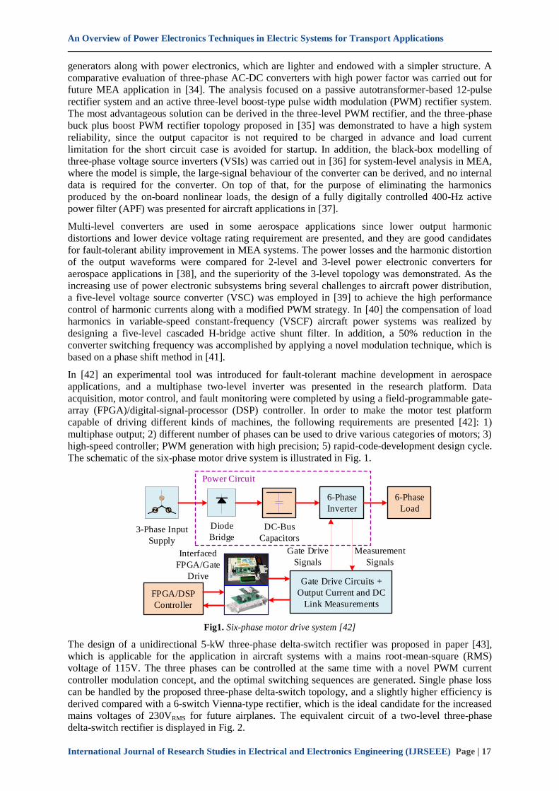
An attractive type of AC power distribution network in MEAs is a high-voltage direct current
(HVDC) one, and the power flows among three HVDC electric networks in MEAs were controlled by
a high-frequency transformer, which was included in an isolated multi-port power converter proposed
in [46]. Aiming at controlling the DC-bus voltage, a proportional gain DC-bus voltage droop control
was implemented in all the converters used in the system. The multi-port power converter was
analysed by modelling it as a two input and two output system. Such a type of converter is particularly
fitted in multiple voltage electrical systems with storage elements [47]. The topology of the proposed
multi-port power converter is displayed in Fig. 3.
L
N
VSC1
Ldc RdcV1
HVDC1
DC distribution line +270V
-270V
u1
N u2
HB1
HB2
G1
RL2V2
HVDC2+270V
-270V G2
VSC2
N u3
HB3
RL3V3
HVDC3+270V
-270V G3VSC3
L
L
Three-Port Bidirectional Converter
Fig3. Aircraft HVDC electrical network and multi-port converter system for HVDC electrical network power
transfer [46]
3. PE TECHNIQUES IN ES
Recently, electric propulsion has been developed for various types of vessels, thanks to the rapid
development of semiconductor switching devices, which can be applied in high power drives [11].
Owing to the requirement of saving fuel consumption, the use of electric propulsion in commercial
ship applications is widely observed, which substitutes the original mechanical counterparts. In the
future electric ship (ES) applications, multiple energy sources, independent operation of individual
power producers, and energy storage for different types of applications will be allowed for further
optimizing the system efficiency [11].
An Overview of Power Electronics Techniques in Electric Systems for Transport Applications
International Journal of Research Studies in Electrical and Electronics Engineering (IJRSEEE) Page | 19
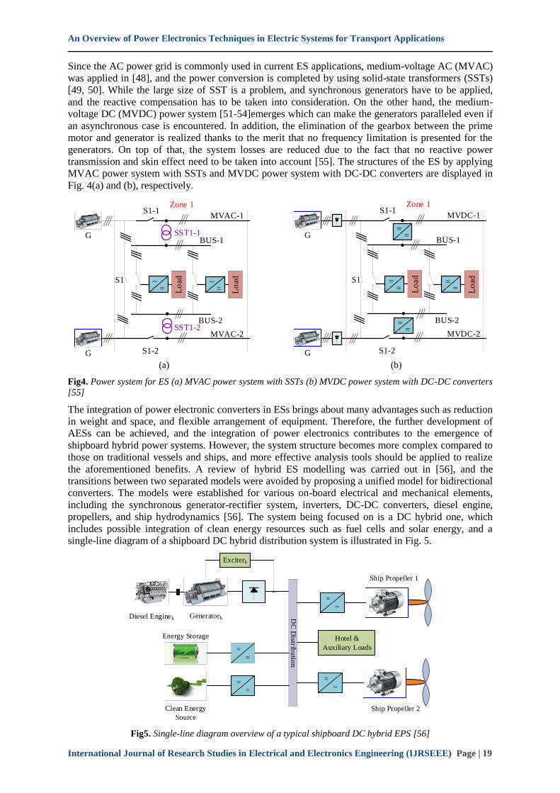
Since the AC power grid is commonly used in current ES applications, medium-voltage AC (MVAC)
was applied in [48], and the power conversion is completed by using solid-state transformers (SSTs)
[49, 50]. While the large size of SST is a problem, and synchronous generators have to be applied,
and the reactive compensation has to be taken into consideration. On the other hand, the medium-
voltage DC (MVDC) power system [51-54]emerges which can make the generators paralleled even if
an asynchronous case is encountered. In addition, the elimination of the gearbox between the prime
motor and generator is realized thanks to the merit that no frequency limitation is presented for the
generators. On top of that, the system losses are reduced due to the fact that no reactive power
transmission and skin effect need to be taken into account [55]. The structures of the ES by applying
MVAC power system with SSTs and MVDC power system with DC-DC converters are displayed in
Fig. 4(a) and (b), respectively.
=~
Lo
ad
G
S1-1
S1-2
SST1-1
SST1-2
=~
Lo
ad
BUS-1
BUS-2
G
S1
Zone 1
MVAC-1
MVAC-2
==
Lo
ad
G
S1-1
S1-2
==
Lo
ad
BUS-1
BUS-2
G
S1
Zone 1
MVDC-1
MVDC-2
==
==
(a) (b)
Fig4. Power system for ES (a) MVAC power system with SSTs (b) MVDC power system with DC-DC converters
[55]
The integration of power electronic converters in ESs brings about many advantages such as reduction
in weight and space, and flexible arrangement of equipment. Therefore, the further development of
AESs can be achieved, and the integration of power electronics contributes to the emergence of
shipboard hybrid power systems. However, the system structure becomes more complex compared to
those on traditional vessels and ships, and more effective analysis tools should be applied to realize
the aforementioned benefits. A review of hybrid ES modelling was carried out in [56], and the
transitions between two separated models were avoided by proposing a unified model for bidirectional
converters. The models were established for various on-board electrical and mechanical elements,
including the synchronous generator-rectifier system, inverters, DC-DC converters, diesel engine,
propellers, and ship hydrodynamics [56]. The system being focused on is a DC hybrid one, which
includes possible integration of clean energy resources such as fuel cells and solar energy, and a
single-line diagram of a shipboard DC hybrid distribution system is illustrated in Fig. 5.
==
==
Exciterk
=~
Hotel &
Auxiliary Loads
=~
DC
Distrib
utio
n
Diesel Enginek Generatork
Energy Storage
Clean Energy
Source
Ship Propeller 1
Ship Propeller 2
Fig5. Single-line diagram overview of a typical shipboard DC hybrid EPS [56]
An Overview of Power Electronics Techniques in Electric Systems for Transport Applications
International Journal of Research Studies in Electrical and Electronics Engineering (IJRSEEE) Page | 20
The modelling of power electronic converters was based on averaging methods, and the computation
burden and time were reduced by neglecting high-frequency switching behaviour. Then a simulation
platform was developed for system-level studies with the application of the obtained models. Since
significant savings in time and computation intensity, the proposed simulation platform can be useful
for studies on AES DC power systems in the long run.
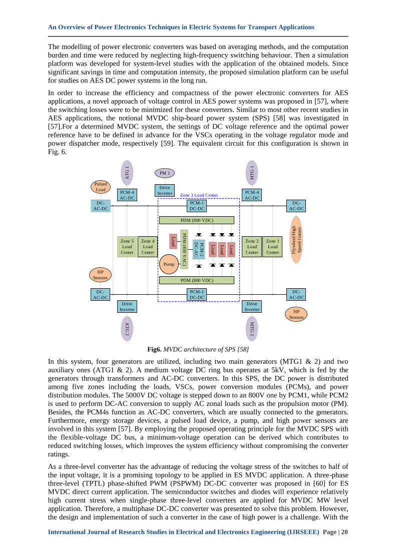
In order to increase the efficiency and compactness of the power electronic converters for AES
applications, a novel approach of voltage control in AES power systems was proposed in [57], where
the switching losses were to be minimized for these converters. Similar to most other recent studies in
AES applications, the notional MVDC ship-board power system (SPS) [58] was investigated in
[57].For a determined MVDC system, the settings of DC voltage reference and the optimal power
reference have to be defined in advance for the VSCs operating in the voltage regulator mode and
power dispatcher mode, respectively [59]. The equivalent circuit for this configuration is shown in
Fig. 6.
Zone 5
Load
Center
DC-
AC-DC
Pulsed
Load
AT
G 1
PCM-4
AC-DC
PM 1
Drive
Inverter
PCM-1
DC-DC
HP
Sensors
DC-
AC-DC
AT
G 2
Drive
Inverter
Zone 4
Load
Center
PCM-1
DC-DC
PDM (800 VDC)
PDM (800 VDC)
Lo
ad
Lo
ad
Lo
ad
PC
M-2
DC
-AC
PD
M (4
50
VA
C)
Lo
ad
Pump
Zone 2
Load
CenterM
TG
1
PCM-4
AC-DC
MT
G 2
Drive
Inverter
Zone 1
Load
Center
DC-
AC-DC
Fly
wh
eel/
Hig
h
Sp
eed
Gen
set
HP
Sensors
DC-
AC-DC
Zone 3 Load Center
Fig6. MVDC architecture of SPS [58]
In this system, four generators are utilized, including two main generators (MTG1 & 2) and two
auxiliary ones (ATG1 & 2). A medium voltage DC ring bus operates at 5kV, which is fed by the
generators through transformers and AC-DC converters. In this SPS, the DC power is distributed
among five zones including the loads, VSCs, power conversion modules (PCMs), and power
distribution modules. The 5000V DC voltage is stepped down to an 800V one by PCM1, while PCM2
is used to perform DC-AC conversion to supply AC zonal loads such as the propulsion motor (PM).
Besides, the PCM4s function as AC-DC converters, which are usually connected to the generators.
Furthermore, energy storage devices, a pulsed load device, a pump, and high power sensors are
involved in this system [57]. By employing the proposed operating principle for the MVDC SPS with
the flexible-voltage DC bus, a minimum-voltage operation can be derived which contributes to
reduced switching losses, which improves the system efficiency without compromising the converter
ratings.
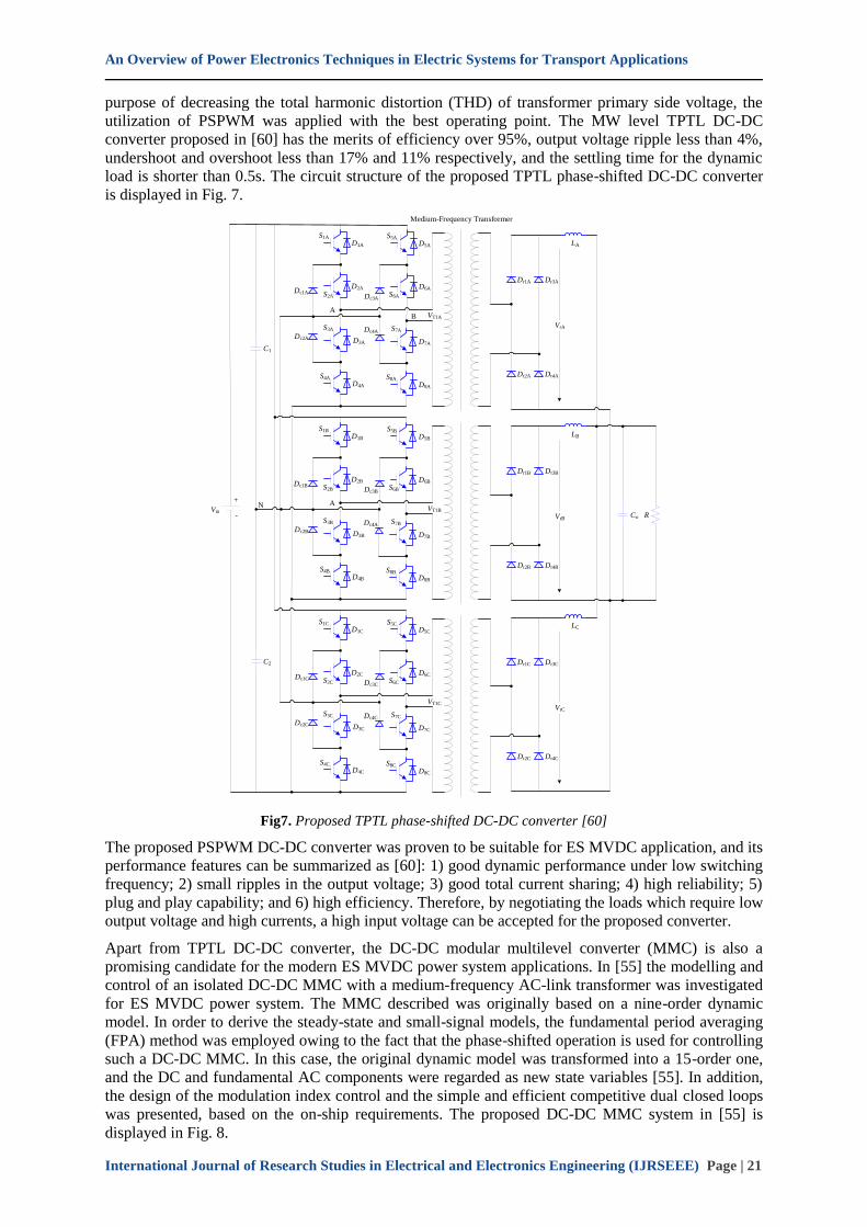
As a three-level converter has the advantage of reducing the voltage stress of the switches to half of
the input voltage, it is a promising topology to be applied in ES MVDC application. A three-phase
three-level (TPTL) phase-shifted PWM (PSPWM) DC-DC converter was proposed in [60] for ES
MVDC direct current application. The semiconductor switches and diodes will experience relatively
high current stress when single-phase three-level converters are applied for MVDC MW level
application. Therefore, a multiphase DC-DC converter was presented to solve this problem. However,
the design and implementation of such a converter in the case of high power is a challenge. With the
An Overview of Power Electronics Techniques in Electric Systems for Transport Applications
International Journal of Research Studies in Electrical and Electronics Engineering (IJRSEEE) Page | 21
purpose of decreasing the total harmonic distortion (THD) of transformer primary side voltage, the
utilization of PSPWM was applied with the best operating point. The MW level TPTL DC-DC
converter proposed in [60] has the merits of efficiency over 95%, output voltage ripple less than 4%,
undershoot and overshoot less than 17% and 11% respectively, and the settling time for the dynamic
load is shorter than 0.5s. The circuit structure of the proposed TPTL phase-shifted DC-DC converter
is displayed in Fig. 7.
S1A
S2A
D1A
D2A
A
Dc1A
S5A
S6A
D5A
D6A
Dc3A
S3A
S4A
D4A
D3ADc2A
S7A
S8A
D8A
D7A
Dc4A
VT1A
+
-
S1B
S2B
D1B
D2B
AN
S5B
S6B
D5B
D6B
Dc3B
S3B
S4B
D4B
D3BDc2B
S7B
S8B
D8B
D7B
Dc4A
VT1B
C1
S1C
S2C
D1C
D2C
S5C
S6C
D5C
D6C
Dc3C
S3C
S4C
D4C
D3CDc2C
S7C
S8C
D8C
D7C
Dc4C
VT1C
C2
Vin
Dc1C
B
Dc1B
Dr1A Dr3A
Dr2A Dr4A
LA
VrA
Dr1B Dr3B
Dr2B Dr4B
LB
VrBCo R
Dr1C Dr3C
Dr2C Dr4C
LC
VrC
Medium-Frequency Transformer
Fig7. Proposed TPTL phase-shifted DC-DC converter [60]
The proposed PSPWM DC-DC converter was proven to be suitable for ES MVDC application, and its
performance features can be summarized as [60]: 1) good dynamic performance under low switching
frequency; 2) small ripples in the output voltage; 3) good total current sharing; 4) high reliability; 5)
plug and play capability; and 6) high efficiency. Therefore, by negotiating the loads which require low
output voltage and high currents, a high input voltage can be accepted for the proposed converter.
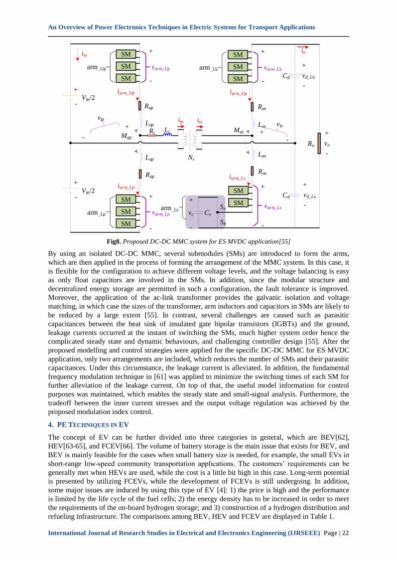
Apart from TPTL DC-DC converter, the DC-DC modular multilevel converter (MMC) is also a
promising candidate for the modern ES MVDC power system applications. In [55] the modelling and
control of an isolated DC-DC MMC with a medium-frequency AC-link transformer was investigated
for ES MVDC power system. The MMC described was originally based on a nine-order dynamic
model. In order to derive the steady-state and small-signal models, the fundamental period averaging
(FPA) method was employed owing to the fact that the phase-shifted operation is used for controlling
such a DC-DC MMC. In this case, the original dynamic model was transformed into a 15-order one,
and the DC and fundamental AC components were regarded as new state variables [55]. In addition,
the design of the modulation index control and the simple and efficient competitive dual closed loops
was presented, based on the on-ship requirements. The proposed DC-DC MMC system in [55] is
displayed in Fig. 8.
An Overview of Power Electronics Techniques in Electric Systems for Transport Applications
International Journal of Research Studies in Electrical and Electronics Engineering (IJRSEEE) Page | 22
+
-Vin/2
SM
SM
SM
Rap
Lap
Rt Lt
iin
arm_Up
iarm_Up
+
-
varm_Up
Lap
Rap
iarm_Lp
SM
SM
SM
arm_Lp
+
varm_Lp
-
+
-Vin/2
vc
+
-
Cs
Sa
Sb
SM
SM
Las
Rasiarm_Ls
Las
Ras
SM
SM
SM
arm_Us
iarm_Up
+
-
varm_Us
Cd
Cd
+
-
vd_Us
io
+
-
vd_Ls
+
-
varm_Ls
Ro
+
-
vo
+
Map-
vtp
+-
vts
arm_Ls
Mas
Nt
itp its
Fig8. Proposed DC-DC MMC system for ES MVDC application[55]
By using an isolated DC-DC MMC, several submodules (SMs) are introduced to form the arms,
which are then applied in the process of forming the arrangement of the MMC system. In this case, it
is flexible for the configuration to achieve different voltage levels, and the voltage balancing is easy
as only float capacitors are involved in the SMs. In addition, since the modular structure and
decentralized energy storage are permitted in such a configuration, the fault tolerance is improved.
Moreover, the application of the ac-link transformer provides the galvanic isolation and voltage
matching, in which case the sizes of the transformer, arm inductors and capacitors in SMs are likely to
be reduced by a large extent [55]. In contrast, several challenges are caused such as parasitic
capacitances between the heat sink of insulated gate bipolar transistors (IGBTs) and the ground,
leakage currents occurred at the instant of switching the SMs, much higher system order hence the
complicated steady state and dynamic behaviours, and challenging controller design [55]. After the
proposed modelling and control strategies were applied for the specific DC-DC MMC for ES MVDC
application, only two arrangements are included, which reduces the number of SMs and their parasitic
capacitances. Under this circumstance, the leakage current is alleviated. In addition, the fundamental
frequency modulation technique in [61] was applied to minimize the switching times of each SM for
further alleviation of the leakage current. On top of that, the useful model information for control
purposes was maintained, which enables the steady state and small-signal analysis. Furthermore, the
tradeoff between the inner current stresses and the output voltage regulation was achieved by the
proposed modulation index control.
4. PE TECHNIQUES IN EV
The concept of EV can be further divided into three categories in general, which are BEV[62],
HEV[63-65], and FCEV[66]. The volume of battery storage is the main issue that exists for BEV, and
BEV is mainly feasible for the cases when small battery size is needed, for example, the small EVs in
short-range low-speed community transportation applications. The customers’ requirements can be
generally met when HEVs are used, while the cost is a little bit high in this case. Long-term potential
is presented by utilizing FCEVs, while the development of FCEVs is still undergoing. In addition,
some major issues are induced by using this type of EV [4]: 1) the price is high and the performance
is limited by the life cycle of the fuel cells; 2) the energy density has to be increased in order to meet
the requirements of the on-board hydrogen storage; and 3) construction of a hydrogen distribution and
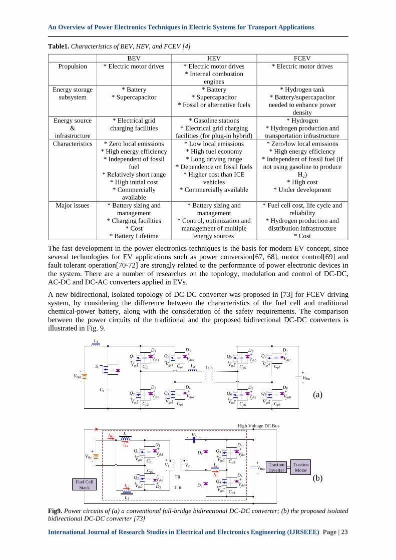
refueling infrastructure. The comparisons among BEV, HEV and FCEV are displayed in Table 1.
An Overview of Power Electronics Techniques in Electric Systems for Transport Applications
International Journal of Research Studies in Electrical and Electronics Engineering (IJRSEEE) Page | 23
Table1. Characteristics of BEV, HEV, and FCEV [4]
BEV HEV FCEV
Propulsion * Electric motor drives * Electric motor drives
* Internal combustion
engines
* Electric motor drives
Energy storage
subsystem
* Battery
* Supercapacitor
* Battery
* Supercapacitor
* Fossil or alternative fuels
* Hydrogen tank
* Battery/supercapacitor
needed to enhance power
density
Energy source
&
infrastructure
* Electrical grid
charging facilities
* Gasoline stations
* Electrical grid charging
facilities (for plug-in hybrid)
* Hydrogen
* Hydrogen production and
transportation infrastructure
Characteristics * Zero local emissions
* High energy efficiency
* Independent of fossil
fuel
* Relatively short range
* High initial cost
* Commercially
available
* Low local emissions
* High fuel economy
* Long driving range
* Dependence on fossil fuels
* Higher cost than ICE
vehicles
* Commercially available
* Zero/low local emissions
* High energy efficiency
* Independent of fossil fuel (if
not using gasoline to produce
H2)
* High cost
* Under development
Major issues * Battery sizing and
management
* Charging facilities
* Cost
* Battery Lifetime
* Battery sizing and
management
* Control, optimization and
management of multiple
energy sources
* Fuel cell cost, life cycle and
reliability
* Hydrogen production and
distribution infrastructure
* Cost
The fast development in the power electronics techniques is the basis for modern EV concept, since
several technologies for EV applications such as power conversion[67, 68], motor control[69] and
fault tolerant operation[70-72] are strongly related to the performance of power electronic devices in
the system. There are a number of researches on the topology, modulation and control of DC-DC,
AC-DC and DC-AC converters applied in EVs.
A new bidirectional, isolated topology of DC-DC converter was proposed in [73] for FCEV driving
system, by considering the difference between the characteristics of the fuel cell and traditional
chemical-power battery, along with the consideration of the safety requirements. The comparison
between the power circuits of the traditional and the proposed bidirectional DC-DC converters is
illustrated in Fig. 9.
VBat
+
-
L1
Sc
Cc
Q1
Vgs1+ -
Cp1
-
+Vds1
D1
Q2
Vgs2+ -
Cp2
-
+Vds2
D2
Q3
Vgs3+ -
Cp3
-
+Vds3
D3
Q4
Vgs4+ -
Cp4
-
+Vds4
D4
Llk 1: n
Q5
Vgs5+ -
Cp5
-
+Vds5
D5
Q6
Vgs6+ -
Cp6
-
+Vds2
D6
Q7
Vgs7+ -
Cp7
-
+Vds7
D7
Q8
Vgs8+ -
Cp8
-
+Vds8
D8
VBus
+
-
(a)
VBat
+
-
L1
Q1
Vgs1+ -
Cp1
-
+Vds1
D1
Q2
Vgs2+ -
Cp2
-
+Vds2
D2 1: n
Q3
Vgs3+ -
Cp3
-
+Vds3
D3
Q4
Vgs4+ -
Cp4
-
+Vds4
D4
VBus
+
-
(b)Fuel Cell
Stack
IL1
L2
IL2
IBar
+
-V1
TR
Lr
ILr
Da
Db
+
-V2
VA +-
Traction
Inverter
Traction
Motor
High Voltage DC Bus
Fig9. Power circuits of (a) a conventional full-bridge bidirectional DC-DC converter; (b) the proposed isolated
bidirectional DC-DC converter [73]
An Overview of Power Electronics Techniques in Electric Systems for Transport Applications
International Journal of Research Studies in Electrical and Electronics Engineering (IJRSEEE) Page | 24
The traditional full-bridge bidirectional DC-DC converter is the best choice for EV applications,
while the complicated configuration, high cost and large size are the main problems in this
configuration. By using the proposed isolated bidirectional DC-DC converter, high efficiency, simple
structure and low cost can be achieved, and the safety requirements for the isolated low- and high-
voltage sides. There are two operation modes for the proposed converter: 1) the boost mode, where
power flows from the low-voltage side (LVS) to the high-voltage side (HVS) and the energy is drawn
from the battery; 2) the buck mode, where the battery is recharged from the high-voltage DC bus.
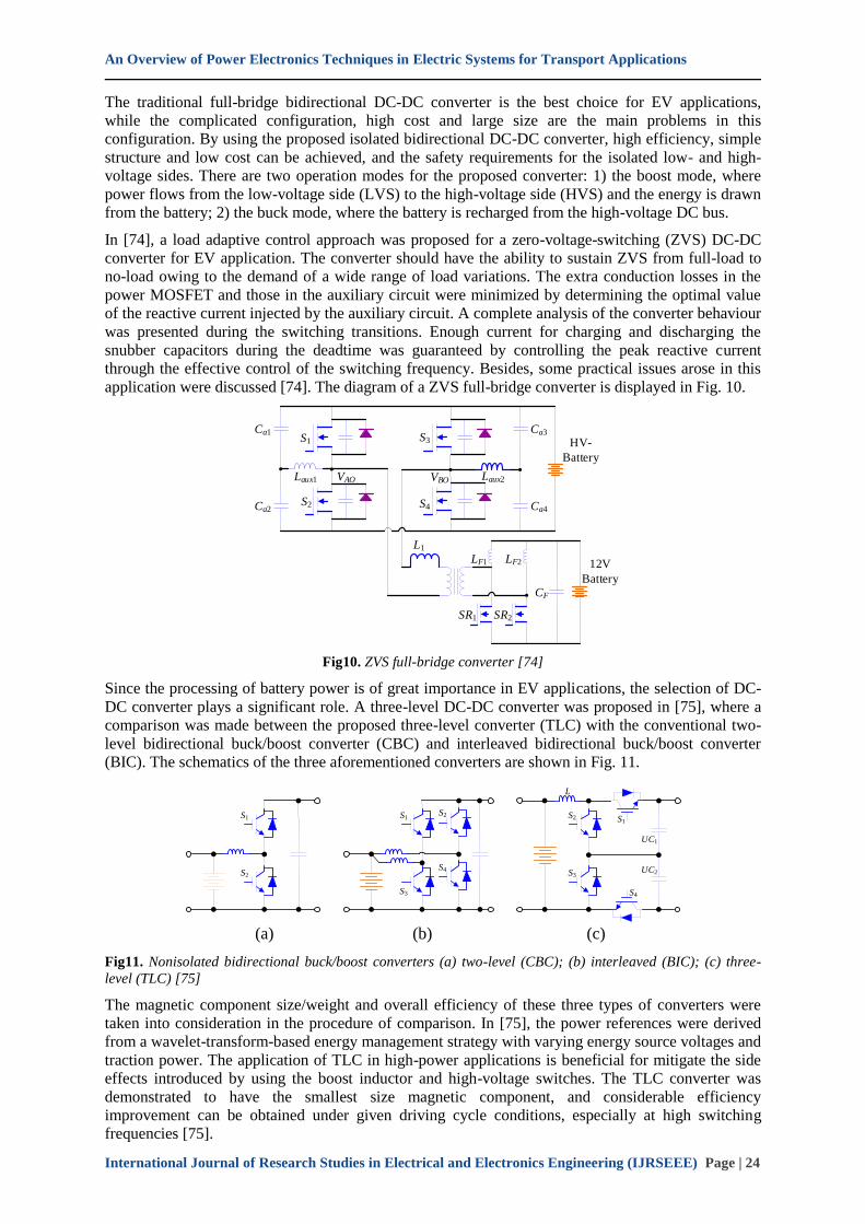
In [74], a load adaptive control approach was proposed for a zero-voltage-switching (ZVS) DC-DC
converter for EV application. The converter should have the ability to sustain ZVS from full-load to
no-load owing to the demand of a wide range of load variations. The extra conduction losses in the
power MOSFET and those in the auxiliary circuit were minimized by determining the optimal value
of the reactive current injected by the auxiliary circuit. A complete analysis of the converter behaviour
was presented during the switching transitions. Enough current for charging and discharging the
snubber capacitors during the deadtime was guaranteed by controlling the peak reactive current
through the effective control of the switching frequency. Besides, some practical issues arose in this
application were discussed [74]. The diagram of a ZVS full-bridge converter is displayed in Fig. 10.
Laux1
Ca1
Ca2
S1
S2
VAO
S3
S4
VBO Laux2
Ca3
Ca4
HV-
Battery
L1
LF1 LF2
CF
12V
Battery
SR1 SR2
Fig10. ZVS full-bridge converter [74]
Since the processing of battery power is of great importance in EV applications, the selection of DC-
DC converter plays a significant role. A three-level DC-DC converter was proposed in [75], where a
comparison was made between the proposed three-level converter (TLC) with the conventional two-
level bidirectional buck/boost converter (CBC) and interleaved bidirectional buck/boost converter
(BIC). The schematics of the three aforementioned converters are shown in Fig. 11.
S2
S1
(a)
S3
S1
(b)
S2
S4S3
S2
(c)
L
S1
S4
UC1
UC2
Fig11. Nonisolated bidirectional buck/boost converters (a) two-level (CBC); (b) interleaved (BIC); (c) three-
level (TLC) [75]
The magnetic component size/weight and overall efficiency of these three types of converters were
taken into consideration in the procedure of comparison. In [75], the power references were derived
from a wavelet-transform-based energy management strategy with varying energy source voltages and
traction power. The application of TLC in high-power applications is beneficial for mitigate the side
effects introduced by using the boost inductor and high-voltage switches. The TLC converter was
demonstrated to have the smallest size magnetic component, and considerable efficiency
improvement can be obtained under given driving cycle conditions, especially at high switching
frequencies [75].
An Overview of Power Electronics Techniques in Electric Systems for Transport Applications
International Journal of Research Studies in Electrical and Electronics Engineering (IJRSEEE) Page | 25
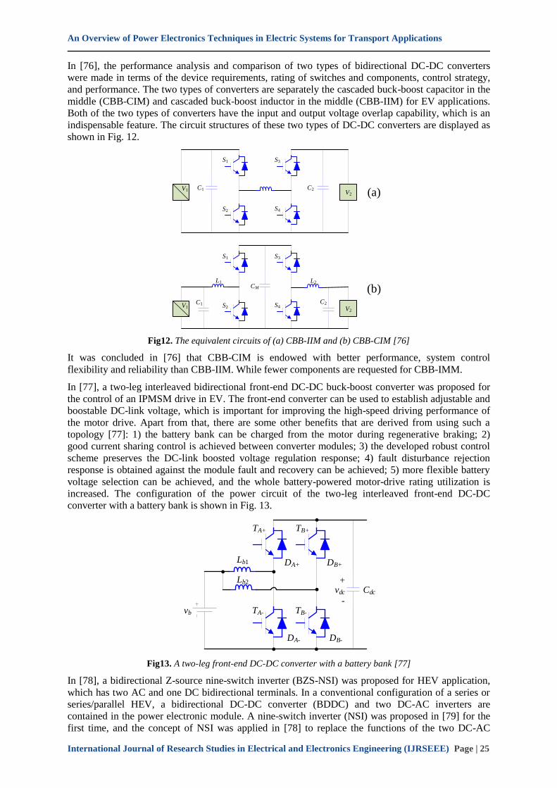
In [76], the performance analysis and comparison of two types of bidirectional DC-DC converters
were made in terms of the device requirements, rating of switches and components, control strategy,
and performance. The two types of converters are separately the cascaded buck-boost capacitor in the
middle (CBB-CIM) and cascaded buck-boost inductor in the middle (CBB-IIM) for EV applications.
Both of the two types of converters have the input and output voltage overlap capability, which is an
indispensable feature. The circuit structures of these two types of DC-DC converters are displayed as
shown in Fig. 12.
S1
C1
S2
L1
S3
S4
C2V1V2 (a)
S1
C1 S2
CM
S3
S4C2V1 V2
(b)L2
Fig12. The equivalent circuits of (a) CBB-IIM and (b) CBB-CIM [76]
It was concluded in [76] that CBB-CIM is endowed with better performance, system control
flexibility and reliability than CBB-IIM. While fewer components are requested for CBB-IMM.
In [77], a two-leg interleaved bidirectional front-end DC-DC buck-boost converter was proposed for
the control of an IPMSM drive in EV. The front-end converter can be used to establish adjustable and
boostable DC-link voltage, which is important for improving the high-speed driving performance of
the motor drive. Apart from that, there are some other benefits that are derived from using such a
topology [77]: 1) the battery bank can be charged from the motor during regenerative braking; 2)
good current sharing control is achieved between converter modules; 3) the developed robust control
scheme preserves the DC-link boosted voltage regulation response; 4) fault disturbance rejection
response is obtained against the module fault and recovery can be achieved; 5) more flexible battery
voltage selection can be achieved, and the whole battery-powered motor-drive rating utilization is
increased. The configuration of the power circuit of the two-leg interleaved front-end DC-DC
converter with a battery bank is shown in Fig. 13.
vb
Lb1
Lb2
TA+
TA-
TB+
TB-
DA+ DB+
DA- DB-
vdc
+
-
Cdc
Fig13. A two-leg front-end DC-DC converter with a battery bank [77]
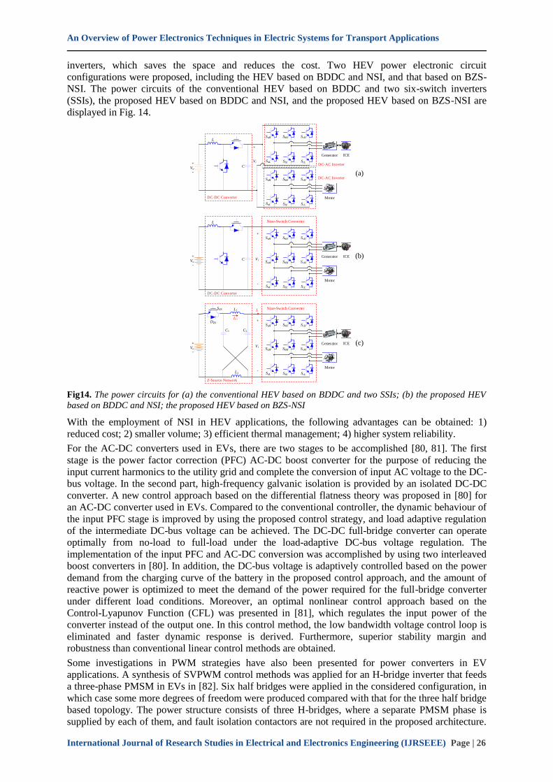
In [78], a bidirectional Z-source nine-switch inverter (BZS-NSI) was proposed for HEV application,
which has two AC and one DC bidirectional terminals. In a conventional configuration of a series or
series/parallel HEV, a bidirectional DC-DC converter (BDDC) and two DC-AC inverters are
contained in the power electronic module. A nine-switch inverter (NSI) was proposed in [79] for the
first time, and the concept of NSI was applied in [78] to replace the functions of the two DC-AC
An Overview of Power Electronics Techniques in Electric Systems for Transport Applications
International Journal of Research Studies in Electrical and Electronics Engineering (IJRSEEE) Page | 26
inverters, which saves the space and reduces the cost. Two HEV power electronic circuit
configurations were proposed, including the HEV based on BDDC and NSI, and that based on BZS-
NSI. The power circuits of the conventional HEV based on BDDC and two six-switch inverters
(SSIs), the proposed HEV based on BDDC and NSI, and the proposed HEV based on BZS-NSI are
displayed in Fig. 14.
Vo
+
-
L
C
SbHSaH ScH
SaL SbL ScL
SbHSaH ScH
SaL SbL ScL
Generator
Motor
ICE
Vi
+
-
(a)
DC-DC Converter
DC-AC Inverter
DC-AC Inverter
Vo
+
-
L
C
SbHSaH ScH
SbMSaM ScM
SaL SbL ScL
Generator
Motor
ICEVi
+
-
(b)
DC-DC Converter
Nine-Switch Converter
Vo
+
-
L1
C2
SbHSaH ScH
SbMSaM ScM
SaL SbL ScL
Generator
Motor
ICEVi
+
-
(c)
Z-Source Network
Nine-Switch ConverterSZS
DZS
C1
IL1
Ii
L2
Fig14. The power circuits for (a) the conventional HEV based on BDDC and two SSIs; (b) the proposed HEV
based on BDDC and NSI; the proposed HEV based on BZS-NSI
With the employment of NSI in HEV applications, the following advantages can be obtained: 1)
reduced cost; 2) smaller volume; 3) efficient thermal management; 4) higher system reliability.
For the AC-DC converters used in EVs, there are two stages to be accomplished [80, 81]. The first
stage is the power factor correction (PFC) AC-DC boost converter for the purpose of reducing the
input current harmonics to the utility grid and complete the conversion of input AC voltage to the DC-
bus voltage. In the second part, high-frequency galvanic isolation is provided by an isolated DC-DC
converter. A new control approach based on the differential flatness theory was proposed in [80] for
an AC-DC converter used in EVs. Compared to the conventional controller, the dynamic behaviour of
the input PFC stage is improved by using the proposed control strategy, and load adaptive regulation
of the intermediate DC-bus voltage can be achieved. The DC-DC full-bridge converter can operate
optimally from no-load to full-load under the load-adaptive DC-bus voltage regulation. The
implementation of the input PFC and AC-DC conversion was accomplished by using two interleaved
boost converters in [80]. In addition, the DC-bus voltage is adaptively controlled based on the power
demand from the charging curve of the battery in the proposed control approach, and the amount of
reactive power is optimized to meet the demand of the power required for the full-bridge converter
under different load conditions. Moreover, an optimal nonlinear control approach based on the
Control-Lyapunov Function (CFL) was presented in [81], which regulates the input power of the
converter instead of the output one. In this control method, the low bandwidth voltage control loop is
eliminated and faster dynamic response is derived. Furthermore, superior stability margin and
robustness than conventional linear control methods are obtained.
Some investigations in PWM strategies have also been presented for power converters in EV
applications. A synthesis of SVPWM control methods was applied for an H-bridge inverter that feeds
a three-phase PMSM in EVs in [82]. Six half bridges were applied in the considered configuration, in
which case some more degrees of freedom were produced compared with that for the three half bridge
based topology. The power structure consists of three H-bridges, where a separate PMSM phase is
supplied by each of them, and fault isolation contactors are not required in the proposed architecture.
An Overview of Power Electronics Techniques in Electric Systems for Transport Applications
International Journal of Research Studies in Electrical and Electronics Engineering (IJRSEEE) Page | 27
In addition, there is no neutral point for the machine connected with the converter with three H-
bridges, thus the full DC-link voltage to each PMSM stator winding can be applied [83, 84], while the
zero-sequence current cannot be structurally rejected. The specific SVPWM method which is most
suitable for EV requirement was selected by combining all the following advantages: switching loss
minimization, balanced switching rate between the three H-bridges, insensitivity to duty cycle,
maximized drive performance, and reduction of the zero-sequence current ripple [82]. In [85], a novel
single-reference six-pulse-modulation (SRSPM) technique was proposed for interleaved high-
frequency (HF) three-phase inverter for FCVs. Compared with the conventional three-reference three-
phase sinusoidal PWM (SPWM), the control complexity is reduced, and the DC-link capacitor is not
required in this case. In addition, only one third modulation of the inverter devices is required for
generating balanced three-phase voltage waveforms, and two thirds of switching losses are
eliminated. Besides, up to 86.6% of switching losses can be reduced compared to a three-phase
inverter. An advanced switching sequence for SVPWM-based three-level neutral-point clamped
(NPC) inverter was proposed in [86] to keep the voltage difference between the two DC-link
capacitors within an acceptable range. The proposed control strategy was based on the nearest three-
vector scheme, and the number of switching sequences is reduced, which endows a constant switching
frequency for the system. Furthermore, the scheme was modified for reduction of lower-order
switching harmonics. In [87], a novel modular multiple-input bidirectional DC-DC power converter
(MIPC) was proposed to interface more than two DC sources of different voltage levels. The
proposed converter has the following features: 1) more than two DC sources of different voltage
levels are likely to be interfaced and they can be extended to any number of sources. 2) Bidirectional
power flow capability is available. 3) The power flow between any two of the sources can be
controlled independently. 4) Simpler design, implementation and control are achieved.
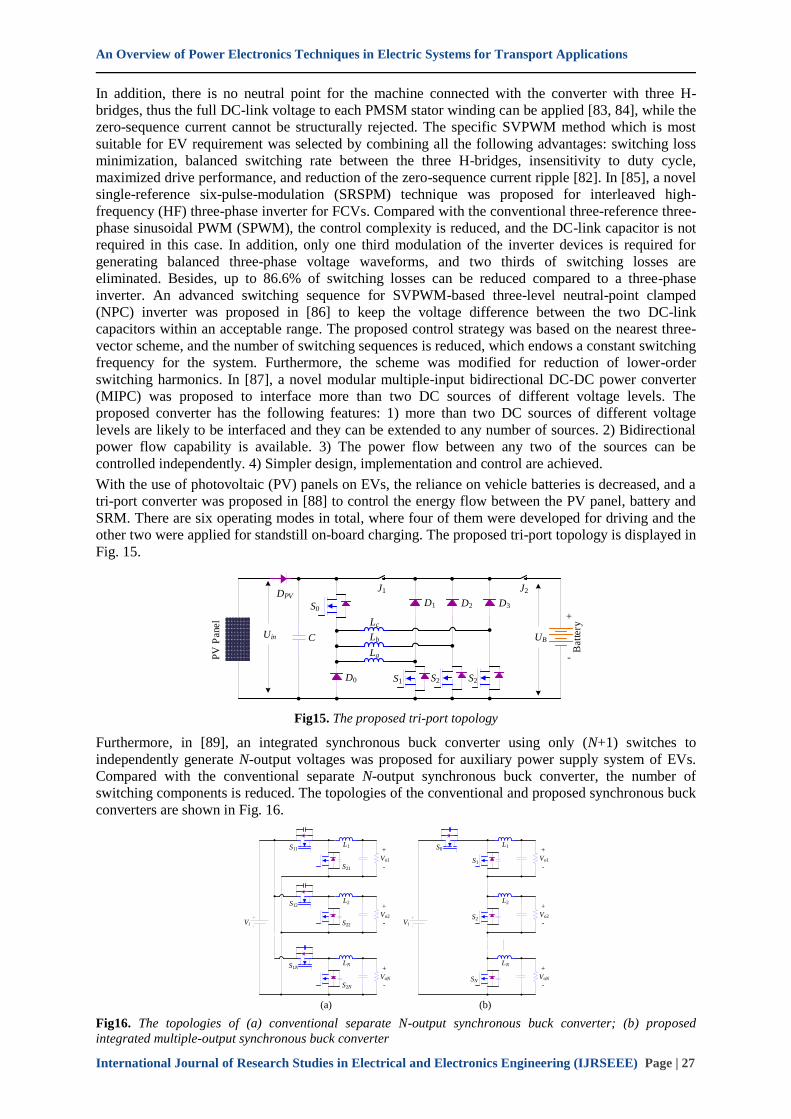
With the use of photovoltaic (PV) panels on EVs, the reliance on vehicle batteries is decreased, and a
tri-port converter was proposed in [88] to control the energy flow between the PV panel, battery and
SRM. There are six operating modes in total, where four of them were developed for driving and the
other two were applied for standstill on-board charging. The proposed tri-port topology is displayed in
Fig. 15.
S0
Uin
PV
Panel
DPV
C
Lc
Lb
La
D0
J1
D1 D2 D3
S1 S2 S2
J2
UB
Batt
ery
+
-
Fig15. The proposed tri-port topology
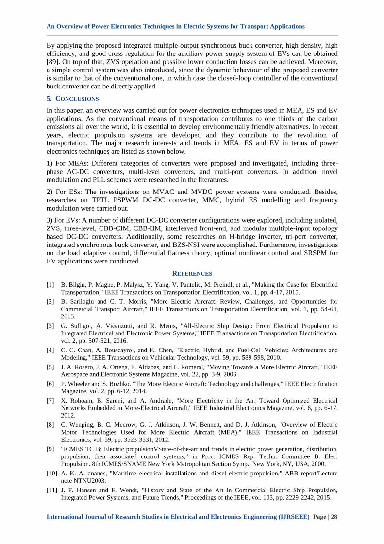
Furthermore, in [89], an integrated synchronous buck converter using only (N+1) switches to
independently generate N-output voltages was proposed for auxiliary power supply system of EVs.
Compared with the conventional separate N-output synchronous buck converter, the number of
switching components is reduced. The topologies of the conventional and proposed synchronous buck
converters are shown in Fig. 16.
Vi
L1S11
S21
Vo1
+
-
L2S12
S22
Vo2
+
-
LNS1N
S2N
VoN
+
-
(a)
Vi
L1S0
S1Vo1
+
-
L2
S2Vo2
+
-
LN
SNVoN
+
-
(b)
Fig16. The topologies of (a) conventional separate N-output synchronous buck converter; (b) proposed
integrated multiple-output synchronous buck converter
An Overview of Power Electronics Techniques in Electric Systems for Transport Applications
International Journal of Research Studies in Electrical and Electronics Engineering (IJRSEEE) Page | 28
By applying the proposed integrated multiple-output synchronous buck converter, high density, high
efficiency, and good cross regulation for the auxiliary power supply system of EVs can be obtained
[89]. On top of that, ZVS operation and possible lower conduction losses can be achieved. Moreover,
a simple control system was also introduced, since the dynamic behaviour of the proposed converter
is similar to that of the conventional one, in which case the closed-loop controller of the conventional
buck converter can be directly applied.
5. CONCLUSIONS
In this paper, an overview was carried out for power electronics techniques used in MEA, ES and EV
applications. As the conventional means of transportation contributes to one thirds of the carbon
emissions all over the world, it is essential to develop environmentally friendly alternatives. In recent
years, electric propulsion systems are developed and they contribute to the revolution of
transportation. The major research interests and trends in MEA, ES and EV in terms of power
electronics techniques are listed as shown below.
1) For MEAs: Different categories of converters were proposed and investigated, including three-
phase AC-DC converters, multi-level converters, and multi-port converters. In addition, novel
modulation and PLL schemes were researched in the literatures.
2) For ESs: The investigations on MVAC and MVDC power systems were conducted. Besides,
researches on TPTL PSPWM DC-DC converter, MMC, hybrid ES modelling and frequency
modulation were carried out.
3) For EVs: A number of different DC-DC converter configurations were explored, including isolated,
ZVS, three-level, CBB-CIM, CBB-IIM, interleaved front-end, and modular multiple-input topology
based DC-DC converters. Additionally, some researches on H-bridge inverter, tri-port converter,
integrated synchronous buck converter, and BZS-NSI were accomplished. Furthermore, investigations
on the load adaptive control, differential flatness theory, optimal nonlinear control and SRSPM for
EV applications were conducted.
REFERENCES
[1] B. Bilgin, P. Magne, P. Malysz, Y. Yang, V. Pantelic, M. Preindl, et al., "Making the Case for Electrified
Transportation," IEEE Transactions on Transportation Electrification, vol. 1, pp. 4-17, 2015.
[2] B. Sarlioglu and C. T. Morris, "More Electric Aircraft: Review, Challenges, and Opportunities for
Commercial Transport Aircraft," IEEE Transactions on Transportation Electrification, vol. 1, pp. 54-64,
2015.
[3] G. Sulligoi, A. Vicenzutti, and R. Menis, "All-Electric Ship Design: From Electrical Propulsion to
Integrated Electrical and Electronic Power Systems," IEEE Transactions on Transportation Electrification,
vol. 2, pp. 507-521, 2016.
[4] C. C. Chan, A. Bouscayrol, and K. Chen, "Electric, Hybrid, and Fuel-Cell Vehicles: Architectures and
Modeling," IEEE Transactions on Vehicular Technology, vol. 59, pp. 589-598, 2010.
[5] J. A. Rosero, J. A. Ortega, E. Aldabas, and L. Romeral, "Moving Towards a More Electric Aircraft," IEEE
Aerospace and Electronic Systems Magazine, vol. 22, pp. 3-9, 2006.
[6] P. Wheeler and S. Bozhko, "The More Electric Aircraft: Technology and challenges," IEEE Electrification
Magazine, vol. 2, pp. 6-12, 2014.
[7] X. Roboam, B. Sareni, and A. Andrade, "More Electricity in the Air: Toward Optimized Electrical
Networks Embedded in More-Electrical Aircraft," IEEE Industrial Electronics Magazine, vol. 6, pp. 6-17,
2012.
[8] C. Wenping, B. C. Mecrow, G. J. Atkinson, J. W. Bennett, and D. J. Atkinson, "Overview of Electric
Motor Technologies Used for More Electric Aircraft (MEA)," IEEE Transactions on Industrial
Electronics, vol. 59, pp. 3523-3531, 2012.
[9] "ICMES TC B; Electric propulsionVState-of-the-art and trends in electric power generation, distribution,
propulsion, their associated control systems," in Proc. ICMES Rep. Techn. Committee B: Elec.
Propulsion. 8th ICMES/SNAME New York Metropolitan Section Symp., New York, NY, USA, 2000.
[10] A. K. A. dnanes, "Maritime electrical installations and diesel electric propulsion," ABB report/Lecture
note NTNU2003.
[11] J. F. Hansen and F. Wendt, "History and State of the Art in Commercial Electric Ship Propulsion,
Integrated Power Systems, and Future Trends," Proceedings of the IEEE, vol. 103, pp. 2229-2242, 2015.
An Overview of Power Electronics Techniques in Electric Systems for Transport Applications
International Journal of Research Studies in Electrical and Electronics Engineering (IJRSEEE) Page | 29
[12] C. C. CHAN, "The State of the Art of Electric and Hybrid Vehicles," PROCEEDINGS OF THE IEEE,
vol. 90, pp. 247-275, 2002.
[13] F. Birol, "Tracking Clean Energy Progress 2016," International Energy Agency, 9 rue de la Fédération,
75739 Paris Cedex 15, France2016.
[14] L. Zheng, T. Zhou, W. Liu, D. Chen, and D. Sun, "A new control method integrated into the coupled map
car-following model for suppressing traffic jams," Nonlinear Dynamics, vol. 88, pp. 663-671, 2016.
[15] S. Whitley, "Time to change the game," Overseas Development Institute, 203 Blackfriars Road,London
SE1 8NJ, UK2013.
[16] F. Blaabjerg, Z. Chen, and S. B. Kjaer, "Power Electronics as Efficient Interface in Dispersed Power
Generation Systems," IEEE Transactions on Power Electronics, vol. 19, pp. 1184-1194, 2004.
[17] C. Xiao, G. Chen, and W. G. H. Odendaal, "Overview of Power Loss Measurement Techniques in Power
Electronics Systems," IEEE Transactions on Industry Applications, vol. 43, pp. 657-664, 2007.
[18] Z. Chen, J. M. Guerrero, and F. Blaabjerg, "A Review of the State of the Art of Power Electronics for
Wind Turbines," IEEE Transactions on Power Electronics, vol. 24, pp. 1859-1875, 2009.
[19] R. Llorente Iglesias, R. Lacal Arantegui, and M. Aguado Alonso, "Power electronics evolution in wind
turbines—A market-based analysis," Renewable and Sustainable Energy Reviews, vol. 15, pp. 4982-4993,
2011.
[20] H. Wang, M. Liserre, and F. Blaabjerg, "Toward Reliable Power Electronics: Challenges, Design Tools,
and Opportunities," IEEE Industrial Electronics Magazine, vol. 7, pp. 17-26, 2013.
[21] F. Blaabjerg and M. Ke, "Future on Power Electronics for Wind Turbine Systems," IEEE Journal of
Emerging and Selected Topics in Power Electronics, vol. 1, pp. 139-152, 2013.
[22] Y. Hu, W. Cao, S. J. Finney, W. Xiao, F. Zhang, and S. F. McLoone, "New Modular Structure DC-DC
Converter Without Electrolytic Capacitors for Renewable Energy Applications," IEEE Transactions on
Sustainable Energy, vol. 5, pp. 1184-1192, 2014.
[23] H. Wang and F. Blaabjerg, "Reliability of Capacitors for DC-Link Applications in Power Electronic
Converters—An Overview," IEEE Transactions on Industry Applications, vol. 50, pp. 3569-3578,
2014.
[24] F. Blaabjerg, K. Ma, and Y. Yang, "Power Electronics – The Key Technology for Renewable Energy
Systems," presented at the 2014 Ninth International Conference on Ecological Vehicles and Renewable
Energies (EVER), Monte-Carlo, Monaco, 2014.
[25] B. Ji, X. Song, E. Sciberras, W. Cao, Y. Hu, and V. Pickert, "Multiobjective Design Optimization of IGBT
Power Modules Considering Power Cycling and Thermal Cycling," IEEE Transactions on Power
Electronics, vol. 30, pp. 2493-2504, 2015.
[26] W. Li, Y. Gu, H. Luo, W. Cui, X. He, and C. Xia, "Topology Review and Derivation Methodology of
Single-Phase Transformerless Photovoltaic Inverters for Leakage Current Suppression," IEEE
Transactions on Industrial Electronics, vol. 62, pp. 4537-4551, 2015.
[27] D. Zhou, F. Blaabjerg, M. Lau, and M. Tonnes, "Optimized Reactive Power Flow of DFIG Power
Converters for Better Reliability Performance Considering Grid Codes," IEEE Transactions on Industrial
Electronics, vol. 62, pp. 1552-1562, 2015.
[28] E. Laloya, O. Lucia, H. Sarnago, and J. M. Burdio, "Heat Management in Power Converters: From State of
the Art to Future Ultrahigh Efficiency Systems," IEEE Transactions on Power Electronics, vol. 31, pp.
7896-7908, 2016.
[29] Q.-C. Zhong, W.-L. Ming, W. Sheng, and Y. Zhao, "Beijing Converters: Bridge Converters With a
Capacitor Added to Reduce Leakage Currents, DC-Bus Voltage Ripples, and Total Capacitance
Required," IEEE Transactions on Industrial Electronics, vol. 64, pp. 325-335, 2017.
[30] K. Rajashekara, "Parallel between More Electric Aircraft and Electric\/Hybrid Vehicle Power Conversion
Technologies," IEEE Electrification Magazine, vol. 2, pp. 50-60, 2014.
[31] M. Olaiya and N. Buchan, "High power variable frequency generator for large civil aircraft," in Proc. IET
Elect. Mach. Syst. More Elect. Aircr, 1999, pp. 1-4.
[32] K. W. E. Cheng, "Comparative study of ac/dc converters for more electric aircraft," in Proc. IEE Conf.
Power Electron. Variable Speed Drives, 1998, pp. 21-23.
[33] M. J. Provost, "The more electric aero-engine: a general overview from an engine manufacturer,"
presented at the Proc. IEE Int. Conf. Power Electronics, Machines and Drives, 2003.
[34] G. Gong, M. L. Heldwein, U. Drofenik, J. Minibock, K. Mino, and J. W. Kolar, "Comparative Evaluation
of Three-Phase High-Power-Factor AC–DC Converter Concepts for Application in Future More Electric
Aircraft," IEEE Transactions on Industrial Electronics, vol. 52, pp. 727-737, 2005.
An Overview of Power Electronics Techniques in Electric Systems for Transport Applications
International Journal of Research Studies in Electrical and Electronics Engineering (IJRSEEE) Page | 30
[35] M. Baumann and J. W. Kolar, "novel control concept for reliable operation of a three-phase three-switch
buck-type unity power factor rectifier with integrated boost output stage under heavily unbalanced mains
condition," in Proc. IEEE PESC’03, 2003, pp. 3-10.
[36] V. Valdivia, A. Lazaro, A. Barrado, P. Zumel, C. Fernandez, and M. Sanz, "Black-Box Modeling of
Three-Phase Voltage Source Inverters for System-Level Analysis," IEEE Transactions on Industrial
Electronics, vol. 59, pp. 3648-3662, 2012.
[37] H. Hu and Y. Xing, "Design Considerations and Fully Digital Implementation of 400-Hz Active Power
Filter for Aircraft Applications," IEEE Transactions on Industrial Electronics, vol. 61, pp. 3823-3834,
2014.
[38] K. D. Papastergiou, P. W. Wheeler, and J. C. Clare, "Comparison of Losses in Multilevel Converters for
Aerospace Applications," presented at the 2008 IEEE Power Electronics Specialists Conference, 2008.
[39] M. Odavic, M. Sumner, and P. Zanchetta, "Multi-sampled carrier-based PWM for multilevel active shunt
power filters for aerospace applications," presented at the Proc. IEEE Energy Convers. Congr. Expo.
(ECCE), 2011.
[40] V. Biagini, P. Zanchetta, M. Odavic, M. Sumner, and M. Degano, "Control and Modulation of a
Multilevel Active Filtering Solution for Variable-Speed Constant-Frequency More-Electric Aircraft
Grids," IEEE Transactions on Industrial Informatics, vol. 9, pp. 600-608, 2013.
[41] M. Odavic, V. Biagini, M. Sumner, P. Zanchetta, and M. Degano, "Multi-sampled carrier-based PWM for
multilevel active shunt power filters for aerospace applications," presented at the Proc. IEEE Energy
Convers. Congr. Expo. (ECCE), 2011.
[42] L. de Lillo, L. Empringham, P. W. Wheeler, S. Khwan-On, C. Gerada, M. N. Othman, et al., "Multiphase
Power Converter Drive for Fault-Tolerant Machine Development in Aerospace Applications," IEEE
Transactions on Industrial Electronics, vol. 57, pp. 575-583, 2010.
[43] M. Hartmann, J. Miniboeck, H. Ertl, and J. W. Kolar, "A Three-Phase Delta Switch Rectifier for Use in
Modern Aircraft," IEEE Transactions on Industrial Electronics, vol. 59, pp. 3635-3647, 2012.
[44] F. Cupertino, E. Lavopa, P. Zanchetta, M. Sumner, and L. Salvatore, "Running DFT-Based PLL
Algorithm for Frequency, Phase, and Amplitude Tracking in Aircraft Electrical Systems," IEEE
Transactions on Industrial Electronics, vol. 58, pp. 1027-1035, 2011.
[45] S. Bifaretti, P. Zanchetta, and E. Lavopa, "Comparison of Two Three-Phase PLL Systems for More
Electric Aircraft Converters," IEEE Transactions on Power Electronics, vol. 29, pp. 6810-6820, 2014.
[46] B. Karanayil, M. Ciobotaru, and V. G. Agelidis, "Power Flow Management of Isolated Multiport
Converter for More Electric Aircraft," IEEE Transactions on Power Electronics, vol. 32, pp. 5850-5861,
2017.
[47] C. Zhao, S. D. Round, and J. W. Kolar, "An Isolated Three-Port Bidirectional DC-DC Converter With
Decoupled Power Flow Management," IEEE Transactions on Power Electronics, vol. 23, pp. 2443-2453,
2008.
[48] S. R. Rudraraju, A. K. Srivastava, S. C. Srivastava, and N. N. Schulz, "Small signal stability analysis of a
shipboard MVDC power system," in Proc. IEEE Electric Ship Technol. Symp., 2009, pp. 135-141.
[49] X. Liu, H. Li, and Z. Wang, "A Start-Up Scheme for a Three-Stage Solid-State Transformer With
Minimized Transformer Current Response," IEEE Transactions on Power Electronics, vol. 27, pp. 4832-
4836, 2012.
[50] S. Xu, A. Q. Huang, and R. Burgos, "Review of Solid-State Transformer Technologies and Their
Application in Power Distribution Systems," IEEE Journal of Emerging and Selected Topics in Power
Electronics, vol. 1, pp. 186-198, 2013.
[51] S. Bose, S. Pal, B. Natarajan, C. M. Scoglio, S. Das, and N. N. Schulz, "Analysis of Optimal
Reconfiguration of Shipboard Power Systems," IEEE Transactions on Power Systems, vol. 27, pp. 189-
197, 2012.
[52] S. Castellan, R. Menis, A. Tessarolo, and G. Sulligoi, "Power electronics for all-electric ships with MVDC
power distribution system: An overview," presented at the Proc. 2014 9th Int. Conf. Ecological Veh.
Renewable Energies, Monte-Carlo, Monaco, 2014.
[53] Y. Guo, M. Khan, M. Faruque, and K. Sun, "Fuzzy logic based energy storage supervision and control
strategy for MVDC power system of all electric ship," presented at the Proc. Power Energy Soc. Gen.
Meet., Boston, MA, USA, 2016.
[54] M. M. S. Khan and M. Faruque, "Management of hybrid energy storage systems for MVDC power system
of all electric ship," presented at the Proc. North Amer. Power Symp., 2016.
[55] Y. Chen, S. Zhao, Z. Li, X. Wei, and Y. Kang, "Modeling and Control of the Isolated DC–DC Modular
Multilevel Converter for Electric Ship Medium Voltage Direct Current Power System," IEEE Journal of
Emerging and Selected Topics in Power Electronics, vol. 5, pp. 124-139, 2017.
An Overview of Power Electronics Techniques in Electric Systems for Transport Applications
International Journal of Research Studies in Electrical and Electronics Engineering (IJRSEEE) Page | 31
[56] B. Zahedi and L. E. Norum, "Modeling and Simulation of All-Electric Ships With Low-Voltage DC
Hybrid Power Systems," IEEE Transactions on Power Electronics, vol. 28, pp. 4525-4537, 2013.
[57] M. Farasat, A. Arabali, and A. M. Trzynadlowski, "Flexible-Voltage DC-Bus Operation for Reduction of
Switching Losses in All-Electric Ship Power Systems," IEEE Transactions on Power Electronics, vol. 29,
pp. 6151-6161, 2014.
[58] I. I. A. Society, "IEEE Recommended Practice for 1 kV to 35 kV Medium-Voltage DC Power Systems on
Ships," vol. IEEE Std 1709™2010, ed. 3 Park Avenue,New York, NY 10016-5997, USA: IEEE, 2010.
[59] P. Kankanala, S. C. Srivastava, A. K. Srivastava, and N. N. Schulz, "Optimal Control of Voltage and
Power in a Multi-Zonal MVDC Shipboard Power System," IEEE TRANSACTIONS ON POWER
SYSTEMS, vol. 27, pp. 642-650, 2012.
[60] G. Yang, F. Xiao, X. Fan, R. Wang, and J. Liu, "Three-Phase Three-Level Phase-Shifted PWM DC–DC
Converter for Electric Ship MVDC Application," IEEE Journal of Emerging and Selected Topics in Power
Electronics, vol. 5, pp. 162-170, 2017.
[61] Y. Chen, Z. Li, S. Zhao, X. Wei, and Y. Kang, "Design and Implementation of a Modular Multilevel
Converter With Hierarchical Redundancy Ability for Electric Ship MVDC System," IEEE Journal of
Emerging and Selected Topics in Power Electronics, vol. 5, pp. 189-202, 2017.
[62] A. M. Omara and M. A. Sleptsov, "Performance Assessment of Battery-Powered Electric Vehicle
Employing PMSM Powertrain System," presented at the Young Researchers in Electrical and Electronic
Engineering (EIConRus), 2017 IEEE Conference of Russian, St. Petersburg, Russia, 2017.
[63] H. Yihua, S. Xueguan, C. Wenping, and J. Bing, "New SR Drive With Integrated Charging Capacity for
Plug-In Hybrid Electric Vehicles (PHEVs)," IEEE Transactions on Industrial Electronics, vol. 61, pp.
5722-5731, 2014.
[64] M. Shahverdi, M. S. Mazzola, Q. Grice, and M. Doude, "Bandwidth-Based Control Strategy for a Series
HEV With Light Energy Storage System," IEEE TRANSACTIONS ON VEHICULAR TECHNOLOGY,
vol. 66, pp. 1040-1052, 2017.
[65] W. Hua, P. Su, M. Tong, and J. Meng, "Investigation of a Five-Phase E-Core Hybrid-Excitation Flux-
Switching Machine for EV and HEV Applications," IEEE TRANSACTIONS ON INDUSTRY
APPLICATIONS, vol. 53, pp. 124-133, 2017.
[66] J.-H. Seo, D.-K. Woo, T.-K. Chung, and H.-K. Jung, "A Study on Loss Characteristics of IPMSM for
FCEV Considering the Rotating Field," IEEE TRANSACTIONS ON MAGNETICS, vol. 46, pp. 3213-
3216, 2010.
[67] T. Park and T. Kim, "Novel Energy Conversion System Based on a Multimode Single-Leg Power
Converter," IEEE Transactions on Power Electronics, vol. 28, pp. 213-220, 2013.
[68] F. Akar, Y. Tavlasoglu, and B. Vural, "An Energy Management Strategy for a Concept
Battery/Ultracapacitor Electric Vehicle With Improved Battery Life," IEEE Transactions on
Transportation Electrification, vol. 3, pp. 191-200, 2017.
[69] I. Boldea, L. N. Tutelea, L. Parsa, and D. Dorrell, "Automotive Electric Propulsion Systems With Reduced
or No Permanent Magnets: An Overview," IEEE Transactions on Industrial Electronics, vol. 61, pp. 5696-
5711, 2014.
[70] M. E. H. Benbouzid, D. Diallo, and M. Zeraoulia, "Advanced Fault-Tolerant Control of Induction-Motor
Drives for EV/HEV Traction Applications: From Conventional to Modern and Intelligent Control
Techniques," IEEE Transactions on Vehicular Technology, vol. 56, pp. 519-528, 2007.
[71] J. Bing, S. Xueguan, C. Wenping, V. Pickert, H. Yihua, J. W. Mackersie, et al., "<italic>In Situ</italic>
Diagnostics and Prognostics of Solder Fatigue in IGBT Modules for Electric Vehicle Drives," IEEE
Transactions on Power Electronics, vol. 30, pp. 1535-1543, 2015.
[72] B. Tabbache, M. Benbouzid, A. Kheloui, and J.-M. Bourgeot, "DSP-Based Sensor Fault Detection and
Post Fault-Tolerant Control of an Induction Motor-Based Electric Vehicle," International Journal of
Vehicular Technology, vol. 2012, pp. 1-7, 2012.
[73] H.-J. Chiu and L.-W. Lin, "A bidirectional DC–DC converter for fuel cell electric vehicle driving system,"
IEEE Transactions on Power Electronics, vol. 21, pp. 950-958, 2006.
[74] M. Pahlevaninezhad, J. Drobnik, P. K. Jain, and A. Bakhshai, "A Load Adaptive Control Approach for a
Zero-Voltage-Switching DC/DC Converter Used for Electric Vehicles," IEEE Transactions on Industrial
Electronics, vol. 59, pp. 920-933, 2012.
[75] S. Dusmez, A. Hasanzadeh, and A. Khaligh, "Comparative Analysis of Bidirectional Three-Level DC &#
x2013;DC Converter for Automotive Applications," IEEE Transactions on Industrial Electronics, vol. 62,
pp. 3305-3315, 2015.
An Overview of Power Electronics Techniques in Electric Systems for Transport Applications
International Journal of Research Studies in Electrical and Electronics Engineering (IJRSEEE) Page | 32
[76] M. A. Khan, A. Ahmed, I. Husain, Y. Sozer, and M. Badawy, "Performance Analysis of Bidirectional
DC–DC Converters for Electric Vehicles," IEEE TRANSACTIONS ON INDUSTRY APPLICATIONS,
vol. 51, pp. 3442-3452, 2015.
[77] Y.-S. Lin, K.-W. Hu, T.-H. Yeh, and C.-M. Liaw, "An Electric-Vehicle IPMSM Drive With Interleaved
Front-End DC/DC Converter," IEEE Transactions on Vehicular Technology, vol. 65, pp. 4493-4504,
2016.
[78] S. M. Dehghan, M. Mohamadian, and A. Yazdian, "Hybrid Electric Vehicle Based on Bidirectional Z-
Source Nine-Switch Inverter," IEEE Transactions on Vehicular Technology, vol. 59, pp. 2641-2653, 2010.
[79] T. Kominami and Y. Fujimoto, "A novel nine-switch inverter for independent control of two three-phase
loads," presented at the Conf. Rec. IEEE IAS Annu. Meeting, 2007.
[80] M. Pahlevaninezhad, P. Das, J. Drobnik, P. K. Jain, and A. Bakhshai, "A New Control Approach Based on
the Differential Flatness Theory for an AC/DC Converter Used in Electric Vehicles," IEEE Transactions
on Power Electronics, vol. 27, pp. 2085-2103, 2012.
[81] M. Pahlevaninezhad, P. Das, J. Drobnik, G. Moschopoulos, P. K. Jain, and A. Bakhshai, "A Nonlinear
Optimal Control Approach Based on the Control-Lyapunov Function for an AC/DC Converter Used in
Electric Vehicles," IEEE Transactions on Industrial Informatics, vol. 8, pp. 596-614, 2012.
[82] A. Kolli, O. Bethoux, A. De Bernardinis, E. Laboure, and G. Coquery, "Space-Vector PWM Control
Synthesis for an H-Bridge Drive in Electric Vehicles," IEEE Transactions on Vehicular Technology, vol.
62, pp. 2441-2452, 2013.
[83] L. D. Sousa and B. Bouchez, "Combined electric device for powering and charging," 2010.
[84] L. D. Sousa, B. Silvestre, and B. Bouchez, "A combined multiphase electric drive and fast battery charger
for electric vehicles topology and electric propulsion efficency analysis," presented at the Conf. Rec. IEEE
VPP, France, 2010.
[85] U. R. Prasanna and A. K. Rathore, "A Novel Single-Reference Six-Pulse-Modulation (SRSPM)
Technique-Based Interleaved High-Frequency Three-Phase Inverter for Fuel Cell Vehicles," IEEE
Transactions on Power Electronics, vol. 28, pp. 5547-5556, 2013.
[86] A. Choudhury, P. Pillay, and S. S. Williamson, "DC-Link Voltage Balancing for a Three-Level Electric
Vehicle Traction Inverter Using an Innovative Switching Sequence Control Scheme," IEEE Journal of
Emerging and Selected Topics in Power Electronics, vol. 2, pp. 296-307, 2014.
[87] A. Hintz, U. R. Prasanna, and K. Rajashekara, "Novel Modular Multiple-Input Bidirectional
DC–DC Power Converter (MIPC) for HEV/FCV Application," IEEE Transactions on Industrial
Electronics, vol. 62, pp. 3163-3172, 2015.
[88] Y. Hu, C. Gan, W. Cao, and Y. Fang, "Tri-Port Converter for Flexible Energy Control of PV-Fed Electric
Vehicles," presented at the Electric Machines & Drives Conference (IEMDC), 2015 IEEE International,
Coeur d'Alene, ID, USA, 2015.
[89] G. Chen, Y. Deng, J. Dong, Y. Hu, L. Jiang, and X. He, "Integrated Multiple-Output Synchronous Buck
Converter for Electric Vehicle Power Supply," IEEE Transactions on Vehicular Technology, vol. 66, pp.
5752-5761, 2017.
Citation: Hui Xu et al, (2017). An Overview of Power Electronics Techniques in Electric Systems for
Transport Applications, International Journal of Research Studies in Electrical and Electronics Engineering
(IJRSEEE), 3(3), pp.15-32, DOI: http://dx.doi.org/10.20431/2454-9436.0303003.
Copyright: © 2017 Hui Xu. This is an open-access article distributed under the terms of the Creative
Commons Attribution License, which permits unrestricted use, distribution, and reproduction in any medium,
provided the original author and source are credited
Recommended


![SinGAPORE AIRLInES A380* 456 ! A380] 333 A380 E 1531 …singapore airlines a380* 456 ! a380] 333 a380 e 1531 a330 [1-2-1 singapore airlines](https://img.pdfslide.us/doc/110x75/5f1f304da44bc1238e46c157/singapore-airlines-a380-456-a380-333-a380-e-1531-singapore-airlines-a380-456.jpg)