8/6/2019 An Led Driver
http://slidepdf.com/reader/full/an-led-driver 1/38

8/6/2019 An Led Driver
http://slidepdf.com/reader/full/an-led-driver 2/38
AN2259
2/38
Figure 1. Board Layout

8/6/2019 An Led Driver
http://slidepdf.com/reader/full/an-led-driver 3/38
AN2259
3/38
Contents
1 DESCRIPTION OF BOARD . . . . . . . . . . . . . . . . . . . . . . . . . . . . . . . . . . . . . . 6
2 INPUT CAPACITOR SELECTION . . . . . . . . . . . . . . . . . . . . . . . . . . . . . . . . . 7
3 CURRENT FEEDBACK LOOP . . . . . . . . . . . . . . . . . . . . . . . . . . . . . . . . . . . . 9
4 INDUCTOR SELECTION . . . . . . . . . . . . . . . . . . . . . . . . . . . . . . . . . . . . . . . 11
5 BOARD LAYOUT . . . . . . . . . . . . . . . . . . . . . . . . . . . . . . . . . . . . . . . . . . . . . 13
6 REFERENCE DESIGN VERSIONS . . . . . . . . . . . . . . . . . . . . . . . . . . . . . . . 16
7 REVISION HISTORY . . . . . . . . . . . . . . . . . . . . . . . . . . . . . . . . . . . . . . . . . . . 36

8/6/2019 An Led Driver
http://slidepdf.com/reader/full/an-led-driver 4/38
AN2259
4/38
Figures
Figure 1. Board Layout . . . . . . . . . . . . . . . . . . . . . . . . . . . . . . . . . . . . . . . . . . . . . . . . 2
Figure 2. Current feedback . . . . . . . . . . . . . . . . . . . . . . . . . . . . . . . . . . . . . . . . . . . . 9
Figure 3. Ripple Current (One 1W LED). . . . . . . . . . . . . . . . . . . . . . . . . . . . . . . . . . 11
Figure 4. Ripple current (One 5W LED) . . . . . . . . . . . . . . . . . . . . . . . . . . . . . . . . . . 12Figure 5. Top side of Board (not in scale) . . . . . . . . . . . . . . . . . . . . . . . . . . . . . . . . 13
Figure 6. Bottom side of Board (not in scale) . . . . . . . . . . . . . . . . . . . . . . . . . . . . . . 13
Figure 7. Board Schematic. . . . . . . . . . . . . . . . . . . . . . . . . . . . . . . . . . . . . . . . . . . . 14
Figure 8. 12Vac Input 1W LED Driver Schematic . . . . . . . . . . . . . . . . . . . . . . . . . . 18
Figure 9. 12Vac Input 3W LED Driver Schematic . . . . . . . . . . . . . . . . . . . . . . . . . . 20
Figure 10. 12Vac Input 5W LED Driver Schematic . . . . . . . . . . . . . . . . . . . . . . . . . . 22
Figure 11. 6 to 12Vdc Input 1W LED Driver Schematic . . . . . . . . . . . . . . . . . . . . . . . 24
Figure 12. 6 to 12Vdc Input 3W LED Driver Schematic . . . . . . . . . . . . . . . . . . . . . . . 26
Figure 13. 6 to 12Vdc Input 5W LED Driver Schematic . . . . . . . . . . . . . . . . . . . . . . . 28
Figure 14. 6 to 24Vdc Input 1W LED Driver Schematic . . . . . . . . . . . . . . . . . . . . . . . 30
Figure 15. 6 to 24Vdc Input 3W LED Driver Schematic . . . . . . . . . . . . . . . . . . . . . . . 32
Figure 16. 6 to 24Vdc Input 5W LED Driver Schematic . . . . . . . . . . . . . . . . . . . . . . . 34

8/6/2019 An Led Driver
http://slidepdf.com/reader/full/an-led-driver 5/38
AN2259
5/38
Tables
Table 1. Bill of Matarials . . . . . . . . . . . . . . . . . . . . . . . . . . . . . . . . . . . . . . . . . . . . . 15
Table 2. Components Changes For Different Configuration . . . . . . . . . . . . . . . . . . 16
Table 3. 12Vac Input 1W LED Driver Bill of Materials. . . . . . . . . . . . . . . . . . . . . . . 19
Table 4. 12Vac Input 3W LED Driver Bill of Materials. . . . . . . . . . . . . . . . . . . . . . . 21Table 5. 12Vac Input 5W LED Driver Bill of Materials. . . . . . . . . . . . . . . . . . . . . . . 23
Table 6. 6 to 12Vdc Input 1W LED Driver Bill of Materials . . . . . . . . . . . . . . . . . . . 25
Table 7. 6 to 12Vdc Input 3W LED Driver Bill of Materials . . . . . . . . . . . . . . . . . . . 27
Table 8. 6 to 12Vdc Input 5W LED Driver Bill of Materials . . . . . . . . . . . . . . . . . . . 29
Table 9. 6 to 24Vdc Input 1W LED Driver Bill of Materials . . . . . . . . . . . . . . . . . . . 31
Table 10. 6 to 24Vdc Input 3W LED Driver Bill of Materials . . . . . . . . . . . . . . . . . . . 33
Table 11. 6 to 24Vdc Input 5W LED Driver Bill of Materials . . . . . . . . . . . . . . . . . . . 35

8/6/2019 An Led Driver
http://slidepdf.com/reader/full/an-led-driver 6/38
1 DESCRIPTION OF BOARD AN2259
6/38
1 DESCRIPTION OF BOARD
The evaluation board shown in Figure 1. was designed so that it can be configured to accept
several different input voltages that are common for automotive and lighting applications. The
most common input voltages are 12Vac, 12Vdc (for automotive) and 24Vdc. The board also
allows the user to select the output current using the jumpers J2 and J4 on the board withouthaving to change any components on the evaluation board. The standard configuration of the
board includes a full wave bridge rectifier that is required for an AC input

8/6/2019 An Led Driver
http://slidepdf.com/reader/full/an-led-driver 7/38
AN2259 2 INPUT CAPACITOR SELECTION
7/38
2 INPUT CAPACITOR SELECTION
For DC input, the input capacitor, C1, is selected based on its ripple current rating for the
capacitor. The ripple current is calculated based on its duty cycle as outlined below.
Where D = duty cycle
Vo = output voltage
Vin = input voltage
The RMS current through the capacitor therefore is:
µ= efficiency
For an AC input voltage, the input capacitor is selected primarily to have enough capacity to
supply the LED between the peaks of the AC input. The capacitor must be selected so that the
minimum voltage at the input to the L5973D is maintained during each half cycle of the AC
input.
If the application is driving only one LED, the Vmin is determined by the minimum operating
voltage specification for the L5973D (4.4V). When driving more than one LED in series, the
minimum input voltage is determined by the output voltage and the minimum differential input tooutput voltage for the regulator (the drop out voltage). In this case Vmin = (x * Vf) + (Iout * Rsense)
+ VDO
Where: x = number of LED in series
Vf = forward voltage of one LED
Io = LED drive current
VDO = Drop out voltage
The capacitor can then be selected using the equation:
The ripple current rating will have two parts where in the low frequency range, the capacitor will
be charged by 120Hz while at the high frequency range the capacitor is discharged by 250kHz.
For the low frequency part, it is approximately the same as the input RMS current and the
power factor is approximately 0.7 for a full wave rectifier.
Vin
VoD =
2
22 DD2
DIoIripple η+η
⋅
−=
Vin2Vpeak ⋅=
)minV2
1Vpeak
2
1(
VoIo105C22
3
⋅−⋅⋅η⋅⋅⋅=
−

8/6/2019 An Led Driver
http://slidepdf.com/reader/full/an-led-driver 8/38
2 INPUT CAPACITOR SELECTION AN2259
8/38
For the high frequency part (ignoring output current ripple), we have:
where Dav is the average duty cycle.
We will use the average duty cycle assuming that the voltage on the capacitor changes from
the peak to the minimum voltage linearly.
The equivalent series resistance of an aluminum capacitor has different frequency
characteristics. There is a coefficient associated with different frequencies. Typically, for 120Hz,
Kfl=1; for frequency greater than 10 kHz, Kfh=1.5.
Therefore, the ripple current rating of the capacitor has to be greater than Icap
7.0Vin
VoIoIin
⋅η⋅
⋅=
IoDavDav2
DavIripple2
22
⋅η
+η
⋅−=
Vav
VoDav =
2
minVVpeak Vav
+=
IoDavDav2DavIripple2
22
⋅η
+η
⋅−=
22
Kfh
Iripple
Kfl
IinIcap
+
=

8/6/2019 An Led Driver
http://slidepdf.com/reader/full/an-led-driver 9/38
AN2259 3 CURRENT FEEDBACK LOOP
9/38
3 CURRENT FEEDBACK LOOP
To drive LEDs in a constant current mode, the feedback for the regulator is taken by sensing
the voltage drop across the current sense resistor, Rs, as shown in Figure 2. The voltage
divider between the sense resistor and the feedback pin (R1 and R2) scales the voltage at the
feedback pin so that it equals the internal reference voltage at the desired current level.
Figure 2. Current feedback
In order to get Io = 350 mA, the values of R1, R2 and Rs are selected based on the following
values.
Vref = 3.3V ; Vfb = 1.235V ; Ifb_bias = 2.5 10 -6 A ; Rs=0.68Ω
Vsense=Rs.Io
Using the superposition method:
Since Vref and Vfb come from same band gap, they are directly correlated. K=Vref/Vfb=2.672.
Therefore, the equation can be simplified to:
For 350mA output the selected values are:
R1 = 2.74kΩ,
R2 =1.30kΩ and
Rs = 0.68Ω.
2R1R2R1Rbias_Ifb
2R1R1RVsense
2R1R2RVref Vfb
+⋅⋅+
+⋅+
+⋅=
2Rbias_Ifb1R
2R)VfbVref (VfbVsense ⋅−⋅−−=
Rs
VsenseIo =
Rs
2Rbias_Ifb1R
2R)VfbVref (Vfb
Io⋅−⋅−−
=
Rs
2Rbias_IfbVfb1R2R)1K(1
Io
⋅−⋅
⋅−−
=

8/6/2019 An Led Driver
http://slidepdf.com/reader/full/an-led-driver 10/38
3 CURRENT FEEDBACK LOOP AN2259
10/38
For an output current of 700mA the value of Rs would be 0.34Ω. If R1 and R2 are small
enough, the effect of the bias current can be ignored.
On the evaluation board, the value of Rs is selected by jumpers J2 and J4. When both J2 and
J4 are open, the output current is set to 350mA. Inserting each jumper connects a 0.68Ω
resistor in parallel with the 0.68Ω Rs. With J2 shorted, the output current will be set to 700mA
and the output current becomes 1A with both J2 and J4 shorted.
8/6/2019 An Led Driver
http://slidepdf.com/reader/full/an-led-driver 11/38
AN2259 4 INDUCTOR SELECTION
11/38
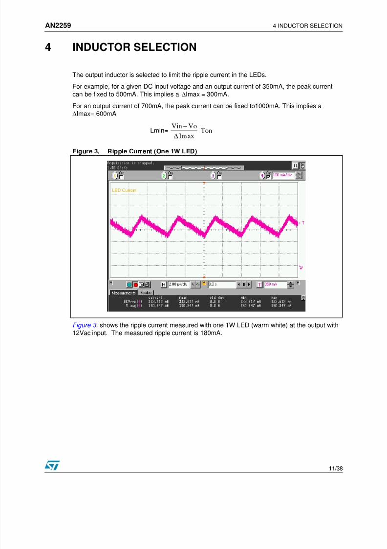
4 INDUCTOR SELECTION
The output inductor is selected to limit the ripple current in the LEDs.
For example, for a given DC input voltage and an output current of 350mA, the peak current
can be fixed to 500mA. This implies a ∆Imax = 300mA.For an output current of 700mA, the peak current can be fixed to1000mA. This implies a
∆Imax= 600mA
Figure 3. Ripple Current (One 1W LED)
Figure 3. shows the ripple current measured with one 1W LED (warm white) at the output with
12Vac input. The measured ripple current is 180mA.
TonaxIm
VoVin⋅
∆
−Lmin=
8/6/2019 An Led Driver
http://slidepdf.com/reader/full/an-led-driver 12/38
4 INDUCTOR SELECTION AN2259
12/38
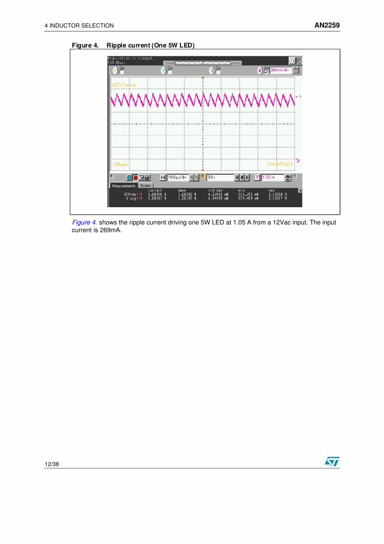
Figure 4. Ripple current (One 5W LED)
Figure 4. shows the ripple current driving one 5W LED at 1.05 A from a 12Vac input. The input
current is 269mA.

8/6/2019 An Led Driver
http://slidepdf.com/reader/full/an-led-driver 13/38

8/6/2019 An Led Driver
http://slidepdf.com/reader/full/an-led-driver 14/38
5 BOARD LAYOUT AN2259
14/38
Figure 7. Board Schematic

8/6/2019 An Led Driver
http://slidepdf.com/reader/full/an-led-driver 15/38
AN2259 5 BOARD LAYOUT
15/38
Table 1. Bill of Matarials
QtyPart
ReferencePart Description Mfg P/N Mfg Geometry Mounting
1 C1 1200uF/35V electrolytic EEU-FC1V22L Panasonic Radial TH
1 C2 220pF/50V ceramic SMD
1 C3 22nF/50V ceramic SMD
1 C4 22nF/50V ceramic SMD
1 C5 4.7nF/50V ceramic SMD
5D2 D4 D5
D6 D7
Low Drop Power
Schottky RectifierSTPS2L40U STMicroelectronics SMB SMD
1 J1Phoenix 2 Pin
ConnectorMKDSN1.5/2 Phoenix Contact TH
1 J2 Current Select Jumper 22-28-8020 Molex TH
1 J3 Stackable Receptacle 535676-5 Tyco TH
1 J4 Current Select Jumper 22-28-8020 Molex 6 Pin TH
1 L1 Inductor DO3316P-683 Coilcraft SMD
1 Q1 PNP Transistor MMBT3906 STMicroelectronics SOT23 SMD
1 Rs 0.68ohms 1% 1/4W 2010 SMD
1 Rs2 0.68ohms 1% 1/4W 2010 SMD
1 Rs3 0.68ohms 1% 1/4W 2010 SMD
1 R1 2.74kohms 1% 1/8W 0805 SMD
1 R2 1.30kohms 1% 1/8W 0805 SMD
1 R3 4.7kohms 5% 1/8W 0805 SMD
1 R4 240kohms 5% 1/8W 0805 SMD
1 U1 Step-down controller L5973D STMicroelectronics SO8 SMD

8/6/2019 An Led Driver
http://slidepdf.com/reader/full/an-led-driver 16/38
6 REFERENCE DESIGN VERSIONS AN2259
16/38
6 REFERENCE DESIGN VERSIONS
The evaluation board is designed to display the full functionality of L5973D as a LED driver to
drive one to three 1W, 3W as well as 5W LEDs at 12Vac input. The components selected for
the demo board are optimized for 5W LED driver application. Based on this circuit, there are
nine different configurations with different input voltages and output power levels that could bederived by making minor components changes to the evaluation board. Table 1. shows the
component changes needed in order to obtain each configuration. The final schematics and bill
of materials for each configuration are shown in the subsequent pages. The 6 to 12 Vdc input
configuration was designed for automotive applications that must survive a reverse battery
condition. In this case one of the rectifiers remains on the board to provide protection against
reversing the power supply leads.
Table 2. Components Changes For Different Configuration
LED Driver U1 D4 D5 D6 D7
12Vac
1W LED
L5970D STPS1L40A STPS1L40A STPS1L40A STPS1L40A
12Vac
3W LEDL5973D STPS2L40U STPS2L40U STPS2L40U STPS2L40U
12Vac
5W LEDL5973D STPS2L40U STPS2L40U STPS2L40U STPS2L40U
6-12Vdc
1W LEDL5970D Not used Not used STPS1L40A Jumper wire
6-12Vdc
3W LEDL5973D Not used Not used STPS2L40U Jumper wire
6-12Vdc
5W LED
L5973D Not used Not used STPS2L40U Jumper wire
6-24Vdc
1W LEDL5970D Not used Not used Jumper wire Jumper wire
6-24Vdc
3W LEDL5973D Not used Not used Jumper wire Jumper wire
6-24Vdc
5W LEDL5973D Not used Not used Jumper wire Jumper wire

8/6/2019 An Led Driver
http://slidepdf.com/reader/full/an-led-driver 17/38
AN2259 6 REFERENCE DESIGN VERSIONS
17/38
Table 2. (Continued)
C1 R2 Rs L1 D2
680uF/35V 1.30k 1% 0.68 47uH STPS1L40A
1200uF/35V 1.33k 1% 0.33 33uH STPS2L40U
1200uF/35V 1.30k 1% 0.24 68uH STPS2L40U
27uF/50V 1.30k 1% 0.68 47uH STPS1L40A
68uF/50V 1.33k 1% 0.33 33uH STPS2L40U
100uF/50V 1.30k 1% 0.24 68uH STPS2L40U
22uF/35V 1.30k 1% 0.68 100uH STPS1L40A
68uF/35V 1.33k 1% 0.33 100uH STPS2L40U
100uF/35V 1.30k 1% 0.24 100uH STPS2L40U
8/6/2019 An Led Driver
http://slidepdf.com/reader/full/an-led-driver 18/38
6 REFERENCE DESIGN VERSIONS AN2259
18/38
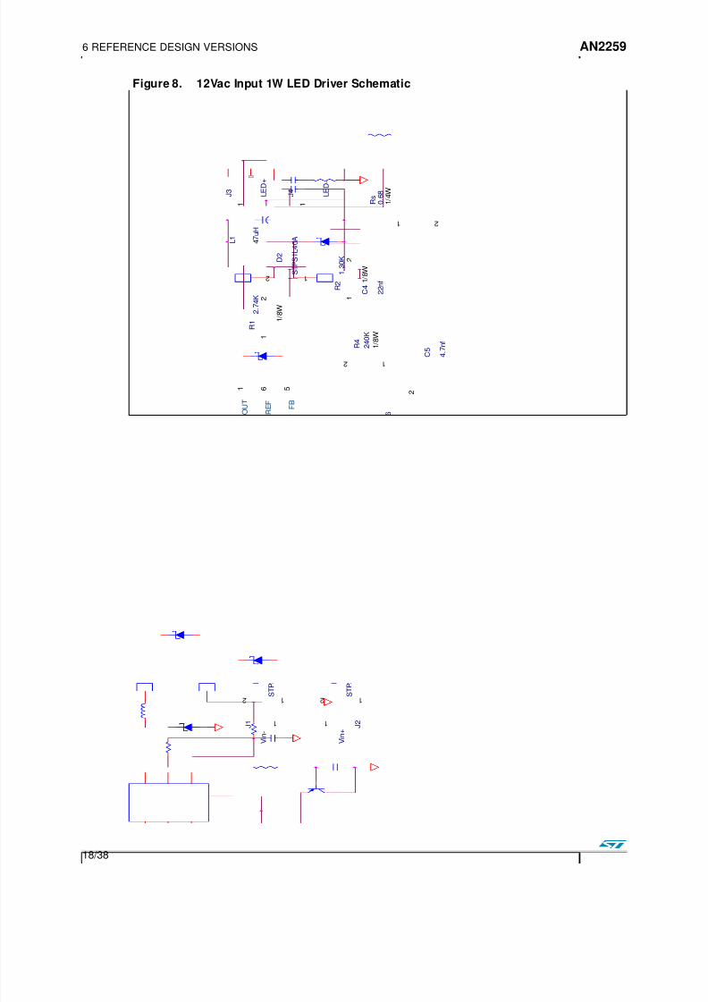
Figure 8. 12Vac Input 1W LED Driver Schematic
1 2
D 7
S T P S 1 L 4 0 A
1 2
D 6
S T P S 1 L 4 0 A
1 2
D 5
S T P S 1 L 4 0 A
1 2
D 2
S T P S 1 L 4 0 A
C 3
2 2 n f
C 4
2 2 n f
G N D7
S Y N C
2
F B
5
C O M P
4
V R E F
6
I N H3
O U T
1
V C C
8
U 1
L 5 9 7 0 D
C 2 2 2 0 p f
+
C 1 6 8 0 u F
3 5 V
C 5 4 . 7 n f
4 7 u H
L 1
1
J 1
V i n -
1
J 2
V i n +
1
2
R 1
2 . 7 4 K
1 / 8 W
1
J 4
L E D -
1
J 3
L E D +
2
1 3
Q 1
M M B T 3 9 0 6
1
2
R 2
1 . 3 0 K
1 / 8 W
1 2
R 3 4 . 7 K
1 / 8 W
1 2
R 4 2 4 0 K
1 / 8 W
1 2
D 4
S T P S 1 L 4 0 A
1 2
R s 0 . 6 8
1 / 4 W
M i n i m u m
i n p u t v o l t a g e
f o r
3
L E D s :
1 0 V
A C
M i n i m u m
i n p u t v o l t a g e
f o r
2
L E D s :
7 . 5
V A C
M i n i m u m
i n p u t v o l t a g e
f o r
1
L E D
:
5 V A C
N o t e :

8/6/2019 An Led Driver
http://slidepdf.com/reader/full/an-led-driver 19/38
AN2259 6 REFERENCE DESIGN VERSIONS
19/38
Table 3. 12Vac Input 1W LED Driver Bill of Materials
Qty ReferencePart
DescriptionMfg P/N Mfg Geometry Mtg
1 C1680uF/35VElectrolytic
EEU-FC1V681 Panasonic Radial TH
1 C2220pF/50V
Ceramic SMD
2 C3, C422nF/50V
CeramicSMD
1 C54.7nF/50V
CeramicSMD
5D2, D4, D5,
D6, D7
Schottky Diode
1A/40VSTPS1L40A STMicroelectronics SMA SMD
1 L1 47uH Inductor DO3308P-473 Coilcraft 9.4mmx12.95mm SMD
1 Q1 PNP Transistor MMBT3906 STMicroelectronics SOT-23 SMD
1 Rs 0.68 Ohm 1% 1206 SMD
1 R1 2.74k 1% 0805 SMD
1 R2 1.30k 1% 0805 SMD
1 R3 4.7k 5% 0805 SMD
1 R4 240k 5% 0805 SMD
1 U1Step-down
controllerL5970D STMicroelectronics 0SO8 SMD

8/6/2019 An Led Driver
http://slidepdf.com/reader/full/an-led-driver 20/38

8/6/2019 An Led Driver
http://slidepdf.com/reader/full/an-led-driver 21/38
AN2259 6 REFERENCE DESIGN VERSIONS
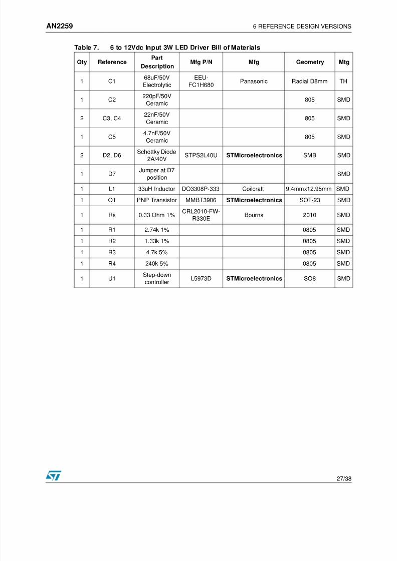
21/38
Table 4. 12Vac Input 3W LED Driver Bill of Materials
Qty ReferencePart
DescriptionMfg P/N Mfg Geometry Mtg
1 C11200uF/35V
Electrolytic
EEU-
FC1V122LPanasonic Radial TH
1 C2 220pF/50VCeramic SMD
2 C3, C422nF/50V
CeramicSMD
1 C54.7nF/50V
CeramicSMD
5D2, D4, D5,
D6, D7
Schottky Diode
2A/40VSTPS2L40U STMicroelectronics SMB SMD
1 L1 33uH Inductor DO3308P-333 Coilcraft 9.4mmx12.95mm SMD
1 Q1 PNP Transistor MMBT3906 STMicroelectronics SOT-23 SMD
1 Rs 0.33 Ohm 1%CRL2010-FW-
R330E Bourns 2010 SMD
1 R1 2.74k 1% 0805 SMD
1 R2 1.33k 1% 0805 SMD
1 R3 4.7k 5% 0805 SMD
1 R4 240k 5% 0805 SMD
1 U1Step-down
controllerL5973D STMicroelectronics SO8 SMD

8/6/2019 An Led Driver
http://slidepdf.com/reader/full/an-led-driver 22/38
6 REFERENCE DESIGN VERSIONS AN2259
22/38
Figure 10. 12Vac Input 5W LED Driver Schematic
1 2
D 2 S T P S 2 L 4 0 U
G N D7
S Y N C
2
F B
5
C O M P
4
V R E F
6
I N H3
O U T
1
V C C
8
U 1
L 5 9 7 3 D
C 2 2 2 0 p f
+
C 1 1 2 0 0 u F
3 5 V
6 8 u H
L 1 D O 3 3 1 6 P - 6 8 3
1 J 1 C O N 1
1J
2 C O N 1
C 3 2 2 n F
R 3 4 . 7 k
1 / 8 W
R 1
2 . 7 4 K
1 / 8 W
1 2
R s 0 . 2 4 O h m
1 / 4 W
1
J 4
C O N
1
1
J 3
C O N 1
C 4 2 2 n f
1 2 R 4 2 4
0 k
1 / 8 W
C 5 4 . 7 n f
2
1 3
Q 1
M M B T 3 9 0 6
D 4 S T P S 2 H 1 0 0 U
D 5
S T P S 2 H 1 0 0 U
D 7 S T P S 2 H 1 0 0 U
V c c
R 2
1 . 3 0 K
1 / 8 W
D 6
S T P S 2 H 1 0 0 U
V i n
-
V i n
+
L E D
-
L E D
+
N o t e :
M i n i m u m
i n p u t v o l t a g e
f o r 1 L E D : 5 V a c
M i n i m u m
i n p u t v o l t a g e
f o r 2 L E D s :
8 V a c
M i n i m u m
i n p u t v o l t a g e
f o r 3 L E D s :
1 0 . 5 V a c

8/6/2019 An Led Driver
http://slidepdf.com/reader/full/an-led-driver 23/38
AN2259 6 REFERENCE DESIGN VERSIONS
23/38
Table 5. 12Vac Input 5W LED Driver Bill of Materials
Qty ReferencePart
DescriptionMfg P/N Mfg Geometry Mtg
1 C11200uF/35V
Electrolytic
EEU-
FC1V122LPanasonic Radial TH
1 C2 220pF/50VCeramic SMD
2 C3, C422nF/50V
CeramicSMD
1 C54.7nF/50V
CeramicSMD
5D2, D4, D5,
D6, D7
Schottky Diode
2A/40VSTPS2L40U STMicroelectronics SMB SMD
1 L1 68uH Inductor DO3316P-683 Coilcraft 9.4mmx12.95mm SMD
1 Q1 PNP Transistor MMBT3906 STMicroelectronics SOT-23 SMD
1 Rs 0.24 Ohm 1%CRL2010-FW-
R240E Bourns 2010 SMD
1 R1 2.74k 1% 0805 SMD
1 R2 1.30k 1% 0805 SMD
1 R3 4.7k 5% 0805 SMD
1 R4 240k 5% 0805 SMD
1 U1Step-down
controllerL5973D STMicroelectronics SO8 SMD

8/6/2019 An Led Driver
http://slidepdf.com/reader/full/an-led-driver 24/38
6 REFERENCE DESIGN VERSIONS AN2259
24/38
Figure 11. 6 to 12Vdc Input 1W LED Driver Schematic
1
2
D 6
S T P S 1 L 4 0 A
1 2
D 2
S T P S 1 L 4 0 A
1
2
D 7 J u m p e r
C 3
2 2 n f
C 4
2 2 n f
G N D7
S Y N C
2
F B
5
C O M P
4
V R E F
6
I N H3
O U T
1
V C C
8
U 1
L 5 9 7 0 D
C 2 2 2 0 p f
+
C 1 2 7 u F
5 0 V
C
5
4
. 7 n f
4 7 u H
L 1
1
J 1 V i n
-
1
J 2 V i n
+
1
2
R 1
2 . 7 4 K
1 / 8 W
1
J 4
L E D -
1
J 3
L E D +
2
1 3
Q 1
M M B T 3 9 0 6
1
2
R 2
1 . 3 0 K
1 / 8 W
1 2
R 3 4 . 7 K
1 / 8 W
1 2
R 4 2 4 0 K
1 / 8 W
1 2
R s 0 . 6 8
1 / 4 W

8/6/2019 An Led Driver
http://slidepdf.com/reader/full/an-led-driver 25/38

8/6/2019 An Led Driver
http://slidepdf.com/reader/full/an-led-driver 26/38
6 REFERENCE DESIGN VERSIONS AN2259
26/38
Figure 12. 6 to 12Vdc Input 3W LED Driver Schematic
1
2
D 6
S T P S 2 L 4 0 U
1 2
D 2
S T P S 2 L 4 0 U
1
2
D 7 J u m p e r
C 3
2 2 n f
C 4
2 2 n f
G N D7
S Y N C
2
F B
5
C O M P
4
V R E F
6
I N H3
O U T
1
V C C
8
U 1
L 5 9 7 3 D
C 2 2 2 0 p f
C 5
4 . 7 n f
3 3 u H
L 1
1
J
1
V
i n - 1
J 2 V i n
+
1
2
R 1
2 . 7 4 K
1 / 8 W
1
J 4
L E D -
1
J 3
L E D +
2
1 3
Q 1
M M B T 3 9 0 6
1
2
R 2
1 . 3 3 K
1 / 8 W
1 2
R 3
4 . 7 K
1 / 8 W
1 2
R 4
2 4 0 K
1 / 8 W
1 2
R s 0 . 3 3
1 / 2 W
+
C 6 6 8 u F
5 0 V
8/6/2019 An Led Driver
http://slidepdf.com/reader/full/an-led-driver 27/38

8/6/2019 An Led Driver
http://slidepdf.com/reader/full/an-led-driver 28/38
6 REFERENCE DESIGN VERSIONS AN2259
28/38
Figure 13. 6 to 12Vdc Input 5W LED Driver Schematic
V c c
1 2
D 2 S T P S 2 L 4 0 U
G N D7
S Y N C
2
F B
5
C O M P
4
V R E F
6
I N H3
O U T
1
V C C
8
U 1
L 5 9 7 3 D
C
2
2
2 0 p F
+
C 1 1 0 0 u F
5 0 V
6 8 u H
L 1 D O 3 3 1 6 P - 6 8 3
1
J 1
C O N 1 1
J 2
C O N 1
C 3 2 2 n F
R 3 4 . 7 k
1 / 8 W
R 1
2 . 7 4 K
1 / 8 W
1 2
R s 0 . 2 4 O h m
1 / 4 W
1
J 4
1 J
3
C 4 2 2 n F
1 2 R 4 2 4 0 k
1 / 8 W
C 5 4 . 7 n F
2
1 3
Q 1
M M B T 3 9 0 6
V c c
R 2
1 . 3 0 K
1 / 8 W
V i n
-
V i n
+
L E D
+
L E D
-
D 6
S T P S 2 H 1 0 0 U
1
2
D 7 J u m p e r

8/6/2019 An Led Driver
http://slidepdf.com/reader/full/an-led-driver 29/38
AN2259 6 REFERENCE DESIGN VERSIONS
29/38
Table 8. 6 to 12Vdc Input 5W LED Driver Bill of Materials
Qty ReferencePart
DescriptionMfg P/N Mfg Geometry Mtg
1 C1100uF/50V
Electrolytic
EEU-
FC1H101Panasonic Radial D8mm TH
1 C2 220pF/50VCeramic 805 SMD
2 C3, C422nF/50V
Ceramic805 SMD
1 C54.7nF/50V
Ceramic805 SMD
2 D2, D6Schottky Diode
2A/40VSTPS2L40U STMicroelectronics SMB SMD
1 D7Jumper at D7
positionSMD
1 L1 68uH Inductor DO3316P-683 Coilcraft 9.4mmx12.95mm SMD
1 Q1 PNP Transistor MMBT3906 STMicroelectronics SOT-23 SMD
1 Rs 0.24 Ohm 1%CRL2010-FW-
R240EBourns 2010 SMD
1 R1 2.74k 1% 0805 SMD
1 R2 1.30k 1% 0805 SMD
1 R3 4.7k 5% 0805 SMD
1 R4 240k 5% 0805 SMD
1 U1Step-down
controllerL5973D STMicroelectronics SO8 SMD

8/6/2019 An Led Driver
http://slidepdf.com/reader/full/an-led-driver 30/38
6 REFERENCE DESIGN VERSIONS AN2259
30/38
Figure 14. 6 to 24Vdc Input 1W LED Driver Schematic
1 2
D 2
S T P S 1 L 4 0 A
1
2
D 7 J u m p e r
C
3
2
2 n f
C 4
2 2 n f
G N D7
S Y N C
2
F B
5
C O M P
4
V R E F
6
I N H3
O U T
1
V C C
8
U 1
L 5 9 7 0 D
C 2 2 2 0 p f
+
C 1 2 2 u F
3 5 V
C 5
4 . 7 n
f
1 0 0 u H
L 1
1
J 1
V i n -
1
J 2
V i n +
1
2
R 1
2 . 7 4 K
1 / 8 W
1
2
D 6 J u m p e r 1
1
J 4
L E D -
1
J 3
L E D +
2
1 3
Q 1
M M B T 3 9 0 6
2 4 V
1
2
R 2
1 . 3 0 K
1 / 8 W
1 2
R 3
4 . 7 K
1 / 8 W
1 2
R
4
2 4 0 K
1 / 8 W
1 2
R s 0 . 6 8
1 / 4 W

8/6/2019 An Led Driver
http://slidepdf.com/reader/full/an-led-driver 31/38
AN2259 6 REFERENCE DESIGN VERSIONS
31/38
Table 9. 6 to 24Vdc Input 1W LED Driver Bill of Materials
Qty ReferencePart
DescriptionMfg P/N Mfg Geometry Mtg
1 C122uF/35V
Electrolytic
EEU-
FC1H220Panasonic Radial TH
1 C2 220pF/50VCeramic SMD
2 C3, C422nF/50V
CeramicSMD
1 C54.7nF/50V
CeramicSMD
1 D2Schottky Diode
1A/40VSTPS1L40A STMicroelectronics SMA SMD
1 D7Jumper at D7
positionSMD
1 D6Jumper at D6
positionSMD
1 L1 100uH Inductor DO3308P-104 Coilcraft9.4mm x
12.95mmSMD
1 Q1 PNP Transistor MMBT3906 STMicroelectronics SOT-23 SMD
1 Rs 0.68 Ohm 1% 1206 SMD
1 R1 2.74k 1% 0805 SMD
1 R2 1.30k 1% 0805 SMD
1 R3 4.7k 5% 0805 SMD
1 R4 240k 5% 0805 SMD
1 U1 Step-downcontroller
L5970D STMicroelectronics SO8 SMD

8/6/2019 An Led Driver
http://slidepdf.com/reader/full/an-led-driver 32/38
6 REFERENCE DESIGN VERSIONS AN2259
32/38
Figure 15. 6 to 24Vdc Input 3W LED Driver Schematic
1 2
D 2
S T P S 2 L 4 0 U
1
2
D
7 J u m p e r
C 3 2 2 n
f
C 4
2 2 n f
G N D7
S Y N C
2
F B
5
C O M P
4
V R E F
6
I N H3
O U T
1
V C C
8
U 1
L 5 9 7 3 D
C 2 2 2 0 p f
C 5
4 . 7 n f
1 0 0 u H
L 1
1
J 1
V i n -
1
J 2
V i n +
1
2
R 1
2 . 7 4 K
1 / 8 W
1
J 4
L E D -
1
J 3
L E D +
2
1 3
Q 1
M M B T 3 9 0 6
1
2
R 2
1 . 3 3 K
1 / 8 W
1 2
R 3
4 . 7 K
1 / 8 W
1
2
D 6 J u m p e r
2 4 V
1 2
R 4 2 4 0 K
1 / 8 W
1 2
R
s
0 . 3 3
1 / 2 W
+
C 1 6 8 u F
3 5 V

8/6/2019 An Led Driver
http://slidepdf.com/reader/full/an-led-driver 33/38

8/6/2019 An Led Driver
http://slidepdf.com/reader/full/an-led-driver 34/38
6 REFERENCE DESIGN VERSIONS AN2259
34/38
Figure 16. 6 to 24Vdc Input 5W LED Driver Schematic
V c c V c c
1 2
D 2 S T P S 2 L 4 0 U
G N D7
S Y N C
2
F B
5
C O M P
4
V R E F
6
I N H3
O U T
1
V C C
8
U 1
L 5 9 7 3 D
C 2 2 2 0
p F
+
C 1 1 0 0 u F
3 5 V
1 0 0 u H
L 1 D O 3 3 1 6 P - 1 0 4
1
J 1
C O N 1 1
J 2
C O N 1
C 3 2 2 n F
R 3 4 . 7 k
1 / 8 W
R 1
2 . 7 4 K
1 / 8 W
1 2
R s 0 . 2 4
1 / 4 W
1
J
1
J 3
C 4 2 2 n F
1 2
R 4 2 4 0 k
1 / 8 W
C
5
4 . 7
n F
2
1 3
Q 1
M M B T 3 9 0 6
R 2
1 . 3 0 K
1 / 8 W
V i n
+
V i n
-
L
L E
1
2
D 7
J u m p e r
1
2
D 6 J u m p e r
V c c

8/6/2019 An Led Driver
http://slidepdf.com/reader/full/an-led-driver 35/38
AN2259 6 REFERENCE DESIGN VERSIONS
35/38
Table 11. 6 to 24Vdc Input 5W LED Driver Bill of Materials
Qty ReferencePart
DescriptionMfg P/N Mfg Geometry Mtg
1 C1100uF/35V
Electrolytic
EEU-
FC1V101Panasonic Radial TH
1 C2 220pF/50VCeramic SMD
2 C3, C422nF/50V
CeramicSMD
1 C54.7nF/50V
CeramicSMD
1 D2Schottky Diode
2A/40VSTPS2L40U STMicroelectronics SMB SMD
1 D6Jumper at D6
positionSMD
1 D7Jumper at D7
positionSMD
1 L1 100uH Inductor DO3316P-104 Coilcraft9.4mm x
12.95mmSMD
1 Q1 PNP Transistor MMBT3906 STMicroelectronics SOT-23 SMD
1 Rs 0.24 Ohm 1%CRL2010-FW-
R240EBourns 2010 SMD
1 R1 2.74k 1% 0805 SMD
1 R2 1.30k 1% 0805 SMD
1 R3 4.7k 5% 0805 SMD
1 R4 240k 5% 0805 SMD
1 U1Step-down
controllerL5973D STMicroelectronics SO8 SMD

8/6/2019 An Led Driver
http://slidepdf.com/reader/full/an-led-driver 36/38
7 REVISION HISTORY AN2259
36/38
7 REVISION HISTORY
Date Revision Changes
04-Nov-2005 1.0 First edition

8/6/2019 An Led Driver
http://slidepdf.com/reader/full/an-led-driver 37/38
AN2259 7 REVISION HISTORY
37/38

8/6/2019 An Led Driver
http://slidepdf.com/reader/full/an-led-driver 38/38
Recommended