Chittur Bala
May 14, 2003
AMS-02 _CDR-fracture.ppt 1
AMS-02 Integration Hardware Fracture
AMS-02 CDR Integration Hardware
Fracture Analysis

Chittur Bala
May 14, 2003
AMS-02 _CDR-fracture.ppt 2
AMS-02 Integration Hardware Fracture• Fracture Control
– Establish fracture control requirements of the AMS-02 payload integration hardware for Space Shuttle and International Space Station (ISS)
– Examine the flight hardware for identification of fracture critical components and implement appropriate inspections, analysis and controls
– Ensure safety of crew, Orbiter and ISS such that failure of any structure will not result in a catastrophic hazard

Chittur Bala
May 14, 2003
AMS-02 _CDR-fracture.ppt 3
AMS-02 Integration Hardware Fracture• Fracture Control (cont)
– Reference documents:- Fracture Control Plan for JSC Flight Hardware
(JSC 25863, Rev. A), August, 1998- Fracture Control Requirements for payloads
using the Space Shuttle (NASA-STD-5003), October, 1996
- Fracture Control Requirements for Space station (SSP 30558, Rev. B, June 1994)
- Fatigue crack Growth Computer program NASGRO version 4.02, September 2002

Chittur Bala
May 14, 2003
AMS-02 _CDR-fracture.ppt 4
AMS-02 Integration Hardware Fracture• Fracture Control (cont)
– Design Safe-life verification for AMS-02 – Combined fatigue loading spectrum derived in
LMSEAT 33818, Rev. A, February 2002.– Spectrum includes Air transport, Truck transport,
Launch/Landing and on-orbit loading events– STA vacuum case includes sine sweep test and
acoustic test spectrums– 3 Orbiter missions for Lift-off/Landing– 3 operational years and 2 contingency years
duration on ISS– Scatter factor of 4 is used for the analysis
Chittur Bala
May 14, 2003
AMS-02 _CDR-fracture.ppt 5
AMS-02 Integration Hardware Fracture• Fracture Control (cont)• Classification of AMS-02 integration Hardware
Components• Non-Fracture Critical Parts
– Low released Mass (<0.25 lb)– Contained– Fail-safe– Low risk

Chittur Bala
May 14, 2003
AMS-02 _CDR-fracture.ppt 6
AMS-02 Integration Hardware Fracture• Fracture Control (cont)• Pressurized Components/Sealed containers
– Non-Hazardous Leak-Before-Burst (LBB) mode of failure
– Through the thickness crack with length 10 times wall thickness will not result in unstable fracture
– Components, lines and fittings comply with NSTS 1700.7B and ISS addendum
– Components are made from metal alloys– Components that sustain continued crack growth
should have safe-life against burst for remaining cycles

Chittur Bala
May 14, 2003
AMS-02 _CDR-fracture.ppt 7
AMS-02 Integration Hardware Fracture• Fracture Control (cont)• Fasteners and shear pins
– To be classified as fail-safe parts they must meet the following requirements:
• Shown by analysis or test that due to a single failure the remaining structure can withstand the loads with a factor of safety of 1.0
• Adequate quality control is implemented to ensure that the remaining structure is unflawed

Chittur Bala
May 14, 2003
AMS-02 _CDR-fracture.ppt 8
AMS-02 Integration Hardware Fracture• Fracture Control (cont)• Fracture Critical components
– Safe-life analysis will be performed with NASGRO program
– Size of flaw will be based on the appropriate NDE techniques or on proof testing
– All fracture critical components will be NDE inspected
– NDE inspections shall be conducted as per standard aerospace quality procedures

Chittur Bala
May 14, 2003
AMS-02 _CDR-fracture.ppt 9
• Vacuum Case Components– Inner cylinder
• Inner cylinder classified as low risk• Material 2219-T852 rolled ring
forging (AMS4144)• NASGRO Model SCO5• Thickness 0.125 in., diameter
44.398 in• Crack size a = 0.025 in., a/c =1.0• Max tensile stress 24842 psi• Analysis done for STA and flight
inner cylinders• Analysis shows that crack growth is
stable

Chittur Bala
May 14, 2003
AMS-02 _CDR-fracture.ppt 10
Crack locationfor inner cylinder

Chittur Bala
May 14, 2003
AMS-02 _CDR-fracture.ppt 11
• Inner cylinder weld– Inner cylinder weld is classified as
fracture critical– Weld properties used from sample tests
done at NASA and LMSO – Dye penetrant and ultrasonic inspection of
the weld will be performed– NASGRO Model SCO5 Thickness 0.259
in., diameter 44.398 in– Crack size a = 0.075 in., a/c =1.0– Max tensile stress 22769 psi– Analysis done for STA and flight inner
cylinders– Analysis shows that crack growth is stable

Chittur Bala
May 14, 2003
AMS-02 _CDR-fracture.ppt 12

Chittur Bala
May 14, 2003
AMS-02 _CDR-fracture.ppt 13
• Conical Flange– Conical flange is classified as low risk– Material 2219-T62 plate– NASGRO Model CCO1 for conical
flange circumferential ribs– Thickness 0.15 in., Width 0.5 in – Crack size a = 0.025 in., a/c =1.0– Max tensile stress 28080 psi– Analysis done for STA and flight
conical flanges– Analysis shows that crack growth is
stable

Chittur Bala
May 14, 2003
AMS-02 _CDR-fracture.ppt 14
• Conical Flange (cont)– NASGRO Model CCO2 at conical
flange bolt locations– Thickness 0.50 in., hole diameter
0.272 in – Crack size a = 0.025 in., a/c =1.0– Max tensile stress S0=12549 psi,
S3= 11647 psi– Analysis done for STA and flight
conical flanges– Analysis shows that crack growth is
stable

Chittur Bala
May 14, 2003
AMS-02 _CDR-fracture.ppt 15
Crack locationCCO1 model
Crack location CCO2 model

Chittur Bala
May 14, 2003
AMS-02 _CDR-fracture.ppt 16
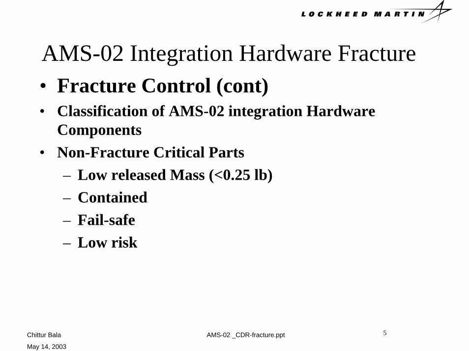
• Support ring– Support ring is classified as low risk– Material 7050-T7451 Rolled ring
forging – NASGRO Model SCO1 at lower
support ring flange– Thickness 0.149 in., width 1.625 in – Crack size a = 0.025 in.,a/c =1.0– Max tensile stress S1= 21594 psi– Analysis done for STA and flight
conical flanges– Analysis shows that crack growth is
stable
Chittur Bala
May 14, 2003
AMS-02 _CDR-fracture.ppt 17
Crack location
Upper ring
Lower ring

Chittur Bala
May 14, 2003
AMS-02 _CDR-fracture.ppt 18
• Support ring (cont)– NASGRO Model SCO1 at upper
support ring flange– Thickness 0.25 in., width 4.625 in – Crack size a = 0.025 in., a/c =1.0– Max tensile stress 23922 psi– Analysis done for STA and flight
conical flanges– Analysis shows that crack growth is
stable

Chittur Bala
May 14, 2003
AMS-02 _CDR-fracture.ppt 19
AMS-02 Integration Hardware Fracture• Outer cylinder
– Outer Cylinder is classified as low risk– Material 7050-T7451 Rolled ring forging – Fracture analysis will be done with low risk crack
size

Chittur Bala
May 14, 2003
AMS-02 _CDR-fracture.ppt 20
AMS-02 Integration Hardware Fracture• USS-02 Components
– Friction stir welded tubes are classified as fracture critical
• Upper trunnion bridge• Lower trunnion bridge• Lower angle tube• Weld properties obtained from tests performed
by NASA and LMSO

Chittur Bala
May 14, 2003
AMS-02 _CDR-fracture.ppt 21
• Upper trunnion bridge– Material 7050-T7451 plate– Inspection as per NASA/JSC PRC-
0014 class A– NASGRO Model SCO1– Thickness 0.25 in. width 6.292 in– Crack size a = 0.10 in., a/c =1.0– Max. tensile stress 24537 psi– Analysis shows that crack growth is
stable

Chittur Bala
May 14, 2003
AMS-02 _CDR-fracture.ppt 22
Friction stir welded tube
Crack location at weld line

Chittur Bala
May 14, 2003
AMS-02 _CDR-fracture.ppt 23
• Lower trunnion bridge– Material 7050-T7451 plate– Inspection as per NASA/JSC PRC-
0014 class A– FLAGRO Model SCO1– Thickness 0.25 in., Width 4.918 in – Crack size a = 0.10 in., a/c =1.0– Max tensile stress 22312 psi– Analysis shows that crack growth is
stable
Chittur Bala
May 14, 2003
AMS-02 _CDR-fracture.ppt 24
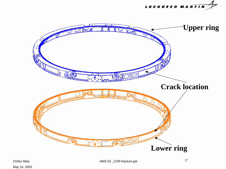
• Lower angle tube– Material 7050-T7451 plate– Inspection as per NASA/JSC PRC-
0014 class A– NASGRO Model SCO1– Thickness 0.25 in., Width 4.562 in – Crack size a = 0.10 in., a/c =1.0– Max tensile stress 18816 psi– Analysis shows that crack growth is
stable

Chittur Bala
May 14, 2003
AMS-02 _CDR-fracture.ppt 25
AMS-02 Integration Hardware Fracture• USS-02 Components (cont)• Fracture analysis for the following items will be done :
– Upper VC joint– Lower VC joint– Sill joints– Diagonal strut– Sill bracket– Diagonal sill bracket– Sill trunnions– Lower center body joint– Keel assembly

Chittur Bala
May 14, 2003
AMS-02 _CDR-fracture.ppt 26
AMS-02 Integration Hardware Fracture• The following items on the Payload attach system
(PAS) are classified as fracture critical:– Platform– Bearing Housing– Bridge beam– Capture bar– Analysis will be done for these items with the
standard dye penetrant NDE crack sizes

Chittur Bala
May 14, 2003
AMS-02 _CDR-fracture.ppt 27
Recommended