AM SERIESDIE-SPLITTERS


MILLUTENSIL is a worldwide leader in the production of die-mould spotting presses and die-splitters which
facilitate safe adjusting, checking and maintenance operations. Founded in 1955, Millutensil always puts the
customer first by engineering innovative, first-rate solutions based upon the needs of their customers. In working
with top-tier companies across a variety of sectors, Millutensil strives for excellence by developing innovative
solutions through cutting-edge technologies. Rather than solely taking on the role of a supplier, Millutensil aims to
be partners with their customers, by providing trusted advice and reliable assistance.
WHY TO INVEST IN A DIE-SPLITTER ?
Some of the fundamental advantages of using a Millutensil die-splitter are as follows:
Considerable reduction of die production costs thanks to time and workforce efficiency
Dies and moulds retain higher quality and longer service life
Improved safety of both on-site personnel and the die itself while reducing liability of dangerous lifting methods (cranes, forklift trucks or lifting equipment)
Optimal accessibility and ergonomics by means of swivelling and tilting plates
Control of parallelism through high-precision linear scales
Sequencing of hydraulic slides, auxiliary cylinders
Streamlined operation through intuitive controls of the next generation Siemens Touch Panel
Modern Diagnostic System
QUALITY,INNOVATIONANDTRADITION

AM DIE-SPLITTERS

THE BEST SOLUTION FOR SAFE SPLITTING, ADJUSTING,MAINTENANCE AND TRY-OUT OPERATIONS ON DIES
Slide in
Opening
Rotating
Tilting

A01-8 Descrizione piano superiore
A01-8 Beschreibung Obertisch
A01-8 Upper platen description
A01-8 Description plateau supérieur
A01AM04
AM06
AM08
AM09
A02-9 Descrizione piano inferiore
A02-9 Beschreibung Untertisch
A02-9 Lower platen description
A02-9 Description plateau inférieur
A02AM04
AM06
AM08
AM09
A03-10 Dimensioni
A03-10 Abmessungen
A03-10 Overall dimensions
A03-10 Encombrement machine
A03AM04
AM06
AM08
AM09
INDEX
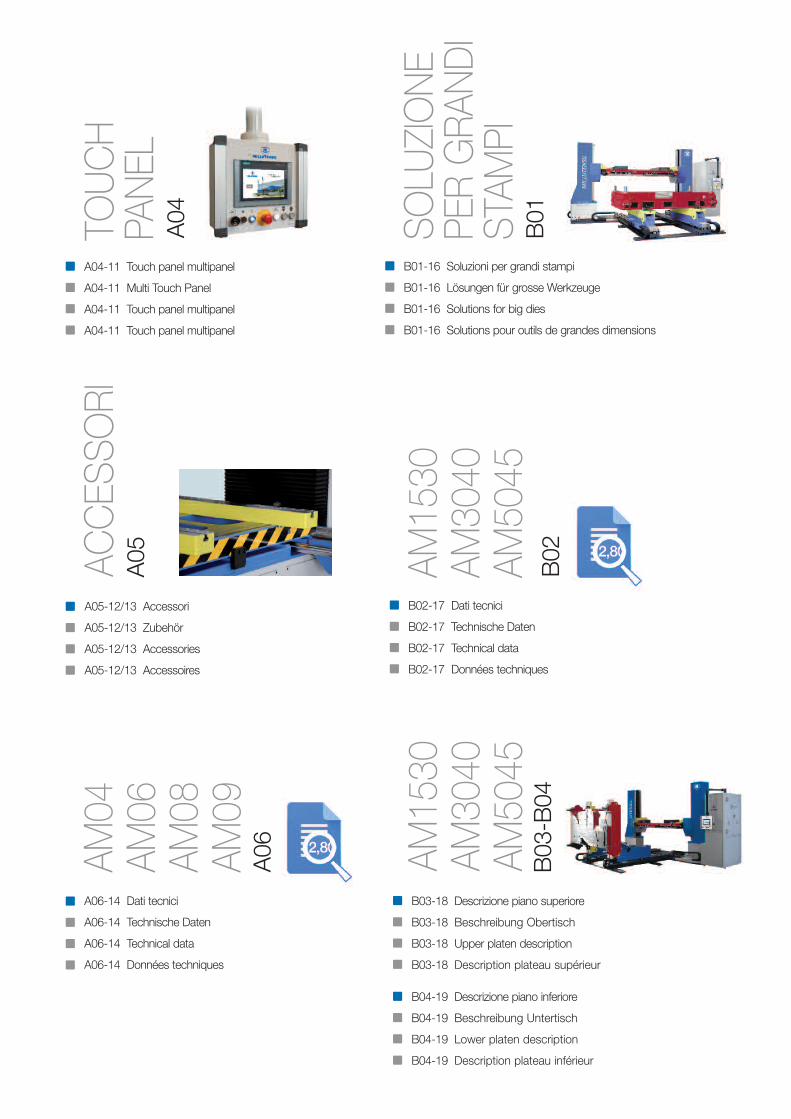
B03-18 Descrizione piano superiore
B03-18 Beschreibung Obertisch
B03-18 Upper platen description
B03-18 Description plateau supérieur
B04-19 Descrizione piano inferiore
B04-19 Beschreibung Untertisch
B04-19 Lower platen description
B04-19 Description plateau inférieur
A04-11 Touch panel multipanel
A04-11 Multi Touch Panel
A04-11 Touch panel multipanel
A04-11 Touch panel multipanel
A05ACCES
SORI
A04TOUCH
PANEL
A06
A05-12/13 Accessori
A05-12/13 Zubehör
A05-12/13 Accessories
A05-12/13 Accessoires
A06-14 Dati tecnici
A06-14 Technische Daten
A06-14 Technical data
A06-14 Données techniques
AM04
AM06
AM08
AM09
B02-17 Dati tecnici
B02-17 Technische Daten
B02-17 Technical data
B02-17 Données techniques
B02AM1530
AM3040
AM5045
AM1530
AM3040
AM5045
B01-16 Soluzioni per grandi stampi
B01-16 Lösungen für grosse Werkzeuge
B01-16 Solutions for big dies
B01-16 Solutions pour outils de grandes dimensions
B01SOLU
ZIONE
PER GRA
NDI
STAM
PIB03-B04
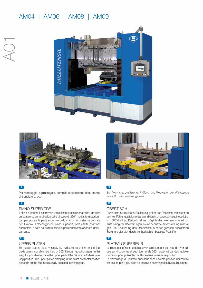
OBERTISCHDurch eine hydraulische Betätigung gleitet der Obertisch senkrecht anden vier Führungssäulen entlang und durch Untersetzungsgetriebe ist erum 360°drehbar. Dadurch ist es möglich das Werkzeugoberteil zurAusführung der Bearbeitungen in eine bequeme Arbeitsstellung zu brin-gen. Die Blockierung des Obertisches in seiner genauen horizontalenStellung ergibt sich durch vier hydraulisch betätigte Passtifte.
PLATEAU SUPERIEURLe plateau supérieur se déplace verticalement par commande hydrauli-que sur 4 colonnes et peut tourner de 360°, actionné par des motoré-ducteurs, pour présenter l’outillage dans la meilleure position.Le verrouillage du plateau supérieur dans l’exacte position horizontaleest assuré par 4 goupilles de précision commandées hydrauliquement.
D
FEN
Per montaggio, aggiustaggio, controllo e riparazione degli stampidi tranciatura, ecc.
PIANO SUPERIOREIl piano superiore è scorrevole verticalmente, con azionamento idraulicosu quattro colonne di guida ed è girevole di 360° mediante motoridut-tori, per portare la parte superiore dello stampo in posizione comodaper il lavoro. Il bloccaggio del piano superiore, nella esatta posizioneorizzontale, è dato da quattro spine di posizionamento azionate idrauli-camente.
UPPER PLATENThe upper platen slides vertically by hydraulic actuation on the fourguide columns and can be tilted by 360° through reduction gears. In thisway, it is possible to place the upper part of the die in an effortless wor-king position. The upper platen clamping in the exact horizontal positiondepends on the four hydraulically actuated locating pegs.
I
BLUE LINE8
I D
A01
AM04 | AM06 | AM08 | AM09
Zur Montage, Justierung, Prüfung und Reparatur der Werkzeugewie z.B. Stanzwerkzeuge usw.

For splitting, adjusting, maintenance and try-out operations ondies etc.
EN F
UNTERTISCHDer ausziehbare, von Kugellagern geführte Untertisch gleitet mit-tels hydraulischem Antrieb auf dem Grundtisch.Er ermöglicht den unteren Teil des Werkzeugs nach aussen und rück-seitig des Werkzeugöffners hin zu bringen und um 90° zu drehen, umden Zugang zu jedem Teil der Werkzeughälfte zu ermöglichen.
PLATEAU INFERIEURLe plateau inférieur montè sur patins à billes coulisse sur le bâti.Ce mouvement est réalisé par un vérin hydraulique. Il peut trans-porter le demi-outil inférieur à l’extérieur et à l’arrière du banc, ilpeut être tourné à 90° pour permettre l’accès à chaque élémentdu bloc.
F
D
PIANO INFERIOREIl piano inferiore è estraibile e scorre sul piano base, guidato da cu-scinetti a sfere, mediante azionamento idraulico.Esso consente di portare la parte inferiore dello stampo esterna-mente e posteriormente all’apristampo e girato di 90° per permet-tere di accedere ad ogni parte del semistampo.
LOWER PLATENThe lower platen is extensible and slides on the base plate, guided byball bearings, through hydraulic drive.It allows to bring the lower part of the die outwards and backwards andto turn it by 90° to allow access to every part of the half die.
I
EN
BLUE LINE 9
A02
Pour le démontage, la maintenance et le remontage des outils, etc.

A x B
1400 x 1070
2000 x 1270
2600 x 1470
3000 x 1470
C
2900
3800
4400
4800
D
2450
2450
2450
2450
E
1500
1900
1900
1900
F
2600
3000
3000
3000
G
920
960
960
960
AM 04
AM 06
AM 08
AM 09
BLUE LINE10
AM04 | AM06 | AM08 | AM09
MODEL
90°
360°
400
1100 E
F
B
1100
G300800
D
C
A
B
1000
T.22
A
90°
360°
A03

BLUE LINE 11
A04
Il PlC elettronICo “SIeMenS S7-1500” geStISCe tutte le funzIonI
Der elektronISChe PlC “SIeMenS S7-1500” verwaltet alle funktIonen
the “SIeMenS S7-1500” eleCtronIC PlC hanDleS all the funCtIonS
le PlC eleCtronIque “SIeMenS S7-1500” CoMManDe touteS leS fonCtIonSF
EN
D
I
TOUCH PANEL MULTIPANEL TP 900

TRAVERSE MOBILI PORTA STAMPO SPECIALI INFUNZIONE DI SPECIFICHE ESIGENZEForniamo traverse porta stampo speciali studiate in base alle diversetipologie di stampo.
FLEXIBLE SPANNSYSTEME FÜR INDIVIDUELLEKUNDENBEDÜRFNISSE UND ALLE WERKZEUGARTENWir liefern Spezialwerkzeugbefestigungstraversen für unter-schiedliche Werkzeugtypologien entwickelt.
SPECIAL DIE HOLDING MOVABLE BEAMS FORSPECIFIC NEEDSWe supply special die holding beams for different dies typologies.
CONSOLES PORTE-OUTIL TYPE PORTIQUE SELONEXIGENCES SPECIFIQUESNous fournissons les supports d’outils type portique spécialementétudiés selon les différents types d’outillages.
FLESSIBILITÀ DI STAFFAGGIO PERLE VARIE TIPOLOGIE DI STAMPI
FLEXIBLE ANORDNUNG DERSPANNSYSTEME FÜR DIEUNTERSCHIEDLICHSTENWERKZEUGSYSTEME
CLAMPING FLEXIBILITY FOR VARIOUSTYPES OF DIES
FLEXIBILITE DE BRIDAGE SELON LESDIFFERENTS TYPES D’OUTILS
I
D
EN
F
I
D
EN
F
BARRE PORTA STAMPO CON INSERTI IDRAULICI ASFERE ROTOBILLEFacilitano la centratura manuale e l’accoppiamento dei duesemistampi dopo eventuali smontaggi.
WERKZEUGHALTEBALKEN MIT HYDRAULISCHENROTOBILLE KUGELEINSÄTZENDiese erleichtern die manuelle Zentrierung und Verkupplung der zweiWerkzeughälften nach eventuellem Ausbau.
DIE HOLDING BEAMS WITH ROTOBILLE BALLHYDRAULIC INSERTSThey facilitate manual centering and coupling of the two half diesafter possible disassembly.
CONSOLES PORTE-OUTIL AVEC INSERTSHYDRAULIQUES TYPE ROTOBILLEEIles facilitent le centrage manuel et le positionnement des deuxparties de l’outil après démontage éventuel.
I
D
EN
F
BLUE LINE12
ACCESSORIESA05
FACILE MOVIMENTAZIONE DELSEMISTAMPO INFERIORE
EINFACHE BEWEGUNG DER UNTERENWERKZEUGHÄLFTE
LOWER HALF DIE EASY HANDLING
MANUTENTION FACILE DE LA PARTIEINFERIEURE DE L’OUTIL
I
D
EN
F

VELOCE, PRATICO, FACILE FISSAGGIODEGLI STAMPI
SCHNELL, PRAKTISCH, EINFACHEBEFESTIGUNG DER WERKZEUGE
FAST, PRACTICAL AND EASY DIECLAMPING
RAPIDE, PRATIQUE, FIXAGE FACILED’OUTILS
I
D
EN
F
PIANI DELLA MACCHINA CON MAGNETI PERMANENTIPermettono un rapido staffaggio dello stampo, disponibili in funzione
dei modelli e delle portate.
WERKZEUGAUFLAGETISCHE MIT PERMANENTMAGNETENDiese erlauben eine schnelle Montage der werkzeuge, erhältlich auf der
Basis der Maschinengrösse und der gewichte.
MACHINE PLATENS WITH PERMANENT MAGNETSfor fast die clamping. available according to model and capacity.
PLATEAUX DE LA MACHINE AVEC AIMANTSPERMANENTSIls permettent une fixation rapide de l’outil, disponibles selon les
modèles et les charges.
I
D
EN
F
BLUE LINE 13
A05
FACILE GESTIONE E COLLAUDODELLE SLITTE IDRAULICHE
EINFACHE VERWALTUNG UNDÜBERPRÜFUNGDER HYDRAULISCHEN SCHLITTEN
SIMPLE HANDLING AND TESTINGOF THE HYDRAULIC SLIDES
GESTION FACILE ET ESSAI DESROTOBILLES HYDRAULIQUES
I
D
EN
F
UNITÀ DI COMANDO CILINDRI AUSILIARIquesto dispositivo idraulico consente di azionare eventuali cilindri
applicati allo stampo per comando parti mobili (max. 2+2).
ANTRIEBSEINHEIT DER KERNZÜGE IN DEM WERKZEUGDiese hydraulische vorrichtung dient zum antrieb eventueller in dem werkzeug
angebrachten zylinder zur kontrolle der beweglichen teile (max. 2+2).
CONTROL UNIT OF AUXILIARY CYLINDERS IN THE DIEthis hydraulic device allows movement of possible cylinders applied
on the die for greater control of mobile parts (max. 2+2).
UNITE DE COMMANDE VERINS DANS LE MOULECe dispositif hydraulique permet d’actionner les vérins fixés dans
le moule, afin de manœuvrer les parties mobiles (maxi. 2+2).
I
D
EN
F

velocità di avvicinamentoannäherungsgeschwindigkeit approaching speedvitesse d’approche
Peso max. per rotazione piano superioreMax. gewicht zur Drehung des obertischesMax load capacity on rotating upper platenPoids maxi. pour la rotation du plateau sup.
Peso max. sul piano inferiore Max. Belastbarkeit auf unterem tisch Max. load capacity on lower platenPoids maxi. sur le plateau inférieur
MODEL
Pressione max. esercizioMax. arbeitsdruck Max. working pressurePression maxi. de service
apertura min. tra i piani einbauhöhe min. Min. opening between platensouverture mini. entre les plateaux
forza max. chiusuraMax. SchliesskraftMax. clamping forceforce maxi. de fermeture
Dimensione dei pianitischaufspannflächePlatens dimensionDimensions des plateaux
velocità di lavoroarbeitsgeschwindigkeit working speedvitesse de travail
Potenza motore principalehauptmotorleistungPower of main enginePuissance du moteur principal
Peso totaleMaschinengewichtMachine weightPoids total
AM 04 AM 06 AM 08 AM 09
kn 60 120 150 160
bar 200 200 200 200
mm1400
x1070
mm 300 300 300 300
mm 1100 1100 1100 1100
kg 4000 6000 8000 9000
kg 1500 3000 3500 4000
mm/s 20 20 20 20
mm/s 6 6 6 6
mm/s 15 15 15 15
kw 4 4 4 4
kg 7500 11200 12800 13500
Colore: grIgIo ral 7035farBe: grau ral 7035Colour: greY ral 7035Couleur: grIS ral 7035
apertura max. tra i piani einbauhöhe max. Max. opening between platensouverture maxi. entre les plateaux
velocità di ritornorücklaufgeschwindigkeit reversing speedvitesse de retour
2000x
1270
2600x
1470
3000x
1470
Parti mobili: Blu ral 5017Bewegliche teile: Blue ral 5017Movable parts: Blue ral 5017Parties mobiles: Bleu ral 5017
BLUE LINE14
A06
TECHNICAL DATA

Working togetherfor your safety

BLUE LINE16
SOLUZIONI PER GRANDI STAMPIMovimento di salita e discesa tramite viti a ricircolo di sfere azionate da motori brushless. Controllo del parallelismo tramite encoder. Gestione conPLC Siemens e comandi tramite touch panel.
LÖSUNGEN FÜR GROSSE WERKZEUGEAuf- und Abwärtsbewegung mittels Kugelumlaufspindeln von Servomotoren angetrieben. Überwachung der Parallelität durch Encoder-Messräder. Steuerung mit Siemens SPS und Befehle über Touch-Panel.
SOLUTIONS FOR BIG DIESUp and down movement by recirculating ball screws activated by brushless motors. Parallelism control through encoders. Monitored throughSiemens PLC commanded by Touch Panel.
SOLUTIONS POUR OUTILS DE GRANDES DIMENSIONSDéplacement de Monte et Baisse par vis à billes entraînées par moteur CC. Contrôle du parallélisme par codeurs. Gestion avec PLCSiemens et commandes par touches tactiles au tableau.
I
D
EN
F
B01
AM1530 | AM3040 | AM5045

B02MODEL
apertura min. tra i pianieinbauhöhe min.Min. opening between platensouverture mini. entre les plateaux
Peso max. sul piano inferioreMax. Belastbarkeit auf unterem tischMax. load capacity on lower platenPoids maxi. sur le plateau inférieur
Dimensione dei pianitischaufspannflächePlatens dimensionDimensions des plateaux
apertura max. tra i pianieinbauhöhe max.Max. opening between platensouverture maxi. entre les plateaux
AM 1530 AM 3040 AM 5045
mm 3000 x 1700 4000 x 2000 4500 x 2800
mm 320 500 500
mm 1450
kg 15000 30000 50000
kg 7000 13000 20000
Peso max. per rotazione piano superioreMax. gewicht zur Drehung des obertischesMax. load capacity on rotating upper platenPoids maxi. pour la rotation du plateau sup.
2100 2200
TECHNICAL DATA
Fast splitting = Time saving

Versione a montanti verticali fissi con piano mobile superiore, ruotabile di180°, provvisto di cave a T per fissaggio stampo.
Ausführung mit zwei feststehenden vertikalen Ständern und einembeweglichen Obertisch, um 180° drehbar, mit T-Nuten versehen zurBefestigung der Werkzeuge.
Version with fixed vertical rods and with movable upper platen, that canbe rotated 180°, equipped with T-slots for die clamping.
Version à montants verticaux fixes avec étage supérieur mobile, pivotantde 180° avec rainures en T pour la fixation des outils.
D
F
EN
I
BLUE LINE18
Versione con un montante verticale fisso e uno mobile per adattarsi allalarghezza stampo, con staffe indipendenti, ruotabili di 180°, per fissaggiodello stampo ai due lati.
Ausführung mit einem feststehenden, vertikalen und einem beweglichenStänder, zur Einstellung auf die richtige Werkzeugbreite. An denDrehlagern werden die Werkzeuge befestigt und können um 180°gedreht werden.
Version with one fixed and one movable vertical rod to adapt to the diewidth, with independent brackets that can be rotated 180° to clamp thedie on both sides.
Version avec un montant vertical fixe et un mobile pour adaptation à lalargeur des outils, avec bridage indépendant, pivotants de 180° pour lafixation des outils des deux côtés.
D
F
EN
I
Versione a montanti verticali fissi con piano mobile superiore, ruotabile di180°, provvisto di traverse mobili per staffaggio stampo regolabili inlarghezza.
Ausführung mit zwei feststehenden vertikalen Ständern und einembeweglichen Obertisch, um 180° drehbar, mit zwei beweglichenTraversen zur Befestigung der Werkzeuge in der Breite anpassbar.
Version with fixed vertical rods and with upper movable platen, that canbe rotated 180°, equipped with die clamping movable beams that canbe adjusted in their width.
Version à montants verticaux fixes avec niveau supérieur mobile, pivotantde 180° pourvus de traverses mobiles pour le bridage d’outils réglablesen largeur.
D
F
EN
I
PIANO SUPERIORE OBERTISCH UPPER PLATE PLATEAU SUPÉRIEUR
B03
AM1530 | AM3040 | AM5045

BLUE LINE 19
PIANO INFERIORE UNTERTISCH LOWER PLATE PLATEAU INFERIEUR
Versione con carro estraibile composto da un piano provvisto di cave aT per fissaggio stampo.
Ausführung mit ausfahrbarem tischwagen mit T-Nuten zurFestspannung des Werkzeuges.
Version with extensible shuttle made up of a platen equipped with T-slotsfor mould clamping.
Version avec plateau sortant composé d’un étage avec rainures en Tpour la fixation des outils.
D
F
EN
I
Versione con due carri estraibili indipendenti adattabili alla larghezzastampo. Per alcune versioni e limitatamente alla portata e’ disponibile ilribaltamento a 90°.
Ausführung mit 2 unabhängigen ausfahrbaren Schlitten, auf die Breitedes Werkzeuges einstellbar. Für gewisse Versionen und gewichtsab-hängig auch mit 90° Kippvorrichtung erhältlich.
Version with two independent extensible shuttles that can be adjusted tothe die width. 90° tilt is available for some versions and depending oncapacity.
Version avec deux chariots indépendants extensibles pour adaptation àla largeur des outils. Basculement à 90° disponible pour certaines ver-sions selon la capacité.
D
F
EN
I
Versione con carro estraibile provvisto di traverse mobili per staffaggiostampo regolabili in larghezza.
Ausführung mit ausfahrbarem Wagen und einstellbaren Traversen.Einstellung der jeweiligen Werkzeugbreite und Festspannung desWerkzeuges.
Version with extensible shuttle equipped with movable beams for dieclamping that can be adjusted in their width.
Version avec plateau sortant pourvu de traverses mobiles pour le fixagedes outils, regables en largeur.
D
F
EN
I
B04

APRISTAMPI BLUE LINEWERKZEUGÖFFNER BLUE LINEBLUE LINE DIE-SPLITTERSBANC D’OUVERTURE DES OUTILS BLUE LINE
BLUE LINE20
PLATENS DIMENSION(MM) - (INCH)MODEL
MAX LOADCAPACITY (KG)
AM 04
AM 06
AM 08
AM 09
1400 x 1070 - 55 x 42
2000 x 1270 - 78 x 50
2600 x 1470 - 102 x 58
3000 x 1470 - 118 x 58
4000
6000
8000
9000
AM SERIES
DIE-SPLITTERS
MAX DIE SIZE(MM) - (INCH)MODEL
MAX LOADCAPACITY (KG)
AM 1530
AM 3040
AM 5045
3000 x 1700 - 118 x 67
4000 x 2000 - 157 x 78
4500 x 2800 - 177 x 110
15000
30000
50000
AM SERIES

PRESSE PROVA STAMPI BLUE LINETUSCHIERPRESSEN BLUE LINEBLUE LINE DIE & MOULD SPOTTING PRESSESPRESSES D’ESSAI DE MOULES BLUE LINE
MIL CLASSIC SERIES
BV SERIES
PLATENS DIMENSION(MM) - (INCH)MODEL CLAMPING FORCE
(TON)
PLATENS DIMENSION(MM) - (INCH)MODEL CLAMPING FORCE
(TON)
MIL 122-123
MIL 142-143
MIL 162-163
MIL 202-203
MIL 252-253
MIL 262-263
MIL 302-303-304
MIL 305
MIL 306
MIL 307
MIL 408
1200 x 1000 - 47 x 39
1400 x 1200 - 55 x 47
1600 x 1300 - 63 x 51
2000 x 1500 - 78 x 59
2500 x 1700 - 98 x 67
2500 x 2000 - 98 x 78
3000 x 2000 - 118 x 78
3000 x 2400 - 118 x 94
3500 x 2400 - 138 x 94
3500 x 2500 - 138 x 98
4000 x 2500 - 157 x 98
60-80
70 -100
100 -150
120 -150
150 -200
150 -200
250 -300 -400
400 - 500
400 - 500
400 - 500
400 - 500
18
30
30
30
50
50
50
50
50
50
50
50
780 x 660 - 31 x 25
980 x 750 - 38 x 29
980 x 750 - 38 x 29
980 x 750 - 38 x 29
1200 x 1000 - 47 x 39
1200 x 1000 - 47 x 39
1200 x 1000 - 47 x 39
1200 x 1000 - 47 x 39
1500 x 1000 - 59 x 39
1500 x 1000 - 59 x 39
1500 x 1000 - 59 x 39
1500 x 1000 - 59 x 39
BV 25P
BV 26C
BV 26E
BV 26E-R
BV 28E
BV 28E-R
BV 28E-G
BV 28E-RG
BV 30E
BV 30E-R
BV 30E-G
BV 30E-RG
MIL COMPACT SERIESPLATENS DIMENSION
(MM) - (INCH)MODEL CLAMPING FORCE(TON)
MIL 2015
MIL 2520
MIL 3020
MIL 3025
MIL 3525
MIL 3030
MIL 3530
MIL 4030
2000 x 1500 - 78 x 59
2500 x 2000 - 98 x 78
3000 x 2000 - 118 x 78
3000 x 2500 - 118 x 98
3500 x 2500 - 138 x 98
3000 x 3000 - 118 x 118
3500 x 3000 - 138 x 118
4000 x 3000 - 157 x 118
120 - 150
150 - 200
250 - 300
250 - 300
300 - 400
300 - 400
300 - 400
300 - 400
BLUE LINE 21
SPOTTING PRESSES
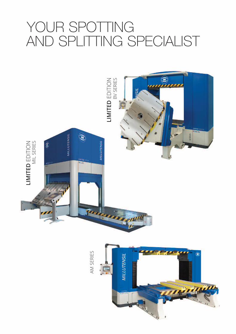
YOUR SPOTTINGAND SPLITTING SPECIALIST
LIM
ITED
ED
ITIO
NM
IL S
ERIE
S
LIM
ITED
ED
ITIO
NBV
SER
IES
AM S
ERIE
S

BE SAFE. BE FAST.

crea
rtcom
.itBLUE LINE.CAT-AM 10/2018 I-D-EN-F
Office Corso Buenos Aires, 9220124 Milano - ItaliaTel. +39 02 29404390Fax +39 02 2046677
Plant Via delle Industrie, 1026010 Izano (CR) - Italia
Recommended