Altivar 66Telemecanique
speed controllersfor asynchronous motors
Constant / variable torque :2.2 to 250 kW, 400 V
Constant / variable torque :3 to 400 HP, 460 V
Constant / variable torque :2.2/3 to 30/37 kW, 230 V
Constant / variable torque :3/5 to 40/50 HP, 230 V
Configuration and adjustment via the terminal
Programming manual
■ Merlin Gerin ■ Square D ■ Telemecanique
efesotomasyon.com

CAUTIONThis document relates to the graphic terminal onthe Altivar 66 with no added options.
Some modes or menus may be modified if thespeed controller has been fitted with one or moreoptions.
Any such modifications are indicated in theaccompanying documentation.
For instructions on how to install, connect andstart the Altivar, refer to the User's Manual.
efesotomasyon.com
1
Contents
Introduction 2 and 3
Principle of access to menus 4
Principle of access in the Main menu 5
Contents of the Main menu 6 and 7
Switch in locked position
Displays on initial power-up 8
Reading the Main menu 9
Display mode during operation 10 and 11
Switch unlocked : partial unlock
Initial power-up : modifying configuration 12 and 13
Review of settings 14 and 15
Total unlock
Access procedure 16
Display configuration 17 and 18
Keypad configuration 19 and 20
General configuration 21 and 22
Drive parameters 23
Motor parameters 24 to 28
Control parameters 29 to 31
Application functions 32 to 57
Output assignment 58 and 59
Fault management 60 to 64
Diagnostic mode 65 and 66
Drive initialization 67 and 68
Memorization configuration and setting 69 to 72
P4P1 P3
P6P6
efesotomasyon.com
2
.
F 1 F 2 F 3
7 8 9
4 5 6
1 2 3
0 •
ESC
ENT
RUN STOP
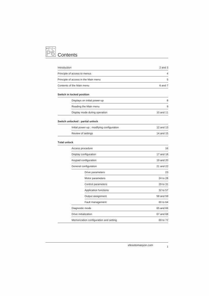
Introduction
Altivar 66 has a removable graphic terminal (keypad) on the front panel.
This graphic terminal is used to :
– Display (in plain language) the speed controller identification, operating parameters or faults.– Modify the settings and configuration of the Altivar.– Select local control mode using the keypad.
Front view
Liquid crystal graphic display (128 x 64 points, with 6lines of 21 characters) which displays bargraphsduring operation, with reverse video to highlight textor a numerical value.
Keypad with 20 keys
1 ENT (enter) key1 ESC (escape) key2 direction keys ▲ ▼11 numerical keys (0 to 9 and the decimal •)3 function keys F1, F2, F32 RUN and STOP keys under a removable protectivecover
Use
ENT key : – go to next menu,– confirm a selection or setting.
ESC key : – return to previous menu,– abandon current setting and return to its original value.
▲ ▼ keys : – scroll through and select from menus,– set a value (in + – mode),– select a function.
Numerical keys : enter or set a value.
F1, F2, F3 keys : can be assigned for local control mode. In programming mode, F1 accesses thehelp menu, F2 returns to Display mode, and F3 provides direct access to a menuor a mode selected by its number.
The RUN and STOP keys are used in local control mode of the speed controller, independentlyof the inputs : starting and stopping the motor on a ramp, if local control mode is selected.
If local control mode has not been selected, the STOP key remains active, and the motor stopsfollowing the deceleration ramp.
efesotomasyon.com
3
Introduction
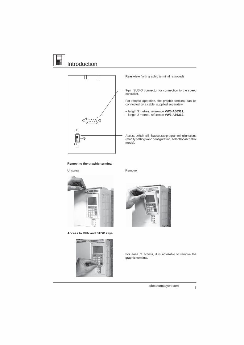
Rear view (with graphic terminal removed)
9-pin SUB-D connector for connection to the speedcontroller.
For remote operation, the graphic terminal can beconnected by a cable, supplied separately :
– length 3 metres, reference VW3-A66311,– length 2 metres, reference VW3-A66312.
Access switch to limit access to programming functions(modify settings and configuration, select local controlmode).
Removing the graphic terminal
Unscrew Remove
Access to RUN and STOP keys
For ease of access, it is advisable to remove thegraphic terminal.
.
efesotomasyon.com
4
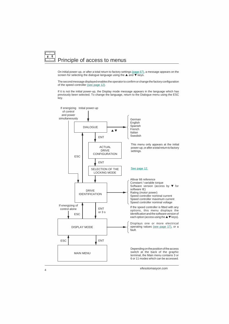
If energizingof control
and powersimultaneously
Initial power-up
DIALOGUE
ACTUALDRIVE
CONFIGURATION
DRIVEIDENTIFICATION
DISPLAY MODE
MAIN MENU
▲ ▼
ENTor 3 s
ENT
ESC
ESC
ESC
SELECTION OF THELOCKING MODE
ENT
ENT
If energizing ofcontrol alone
Principle of access to menus
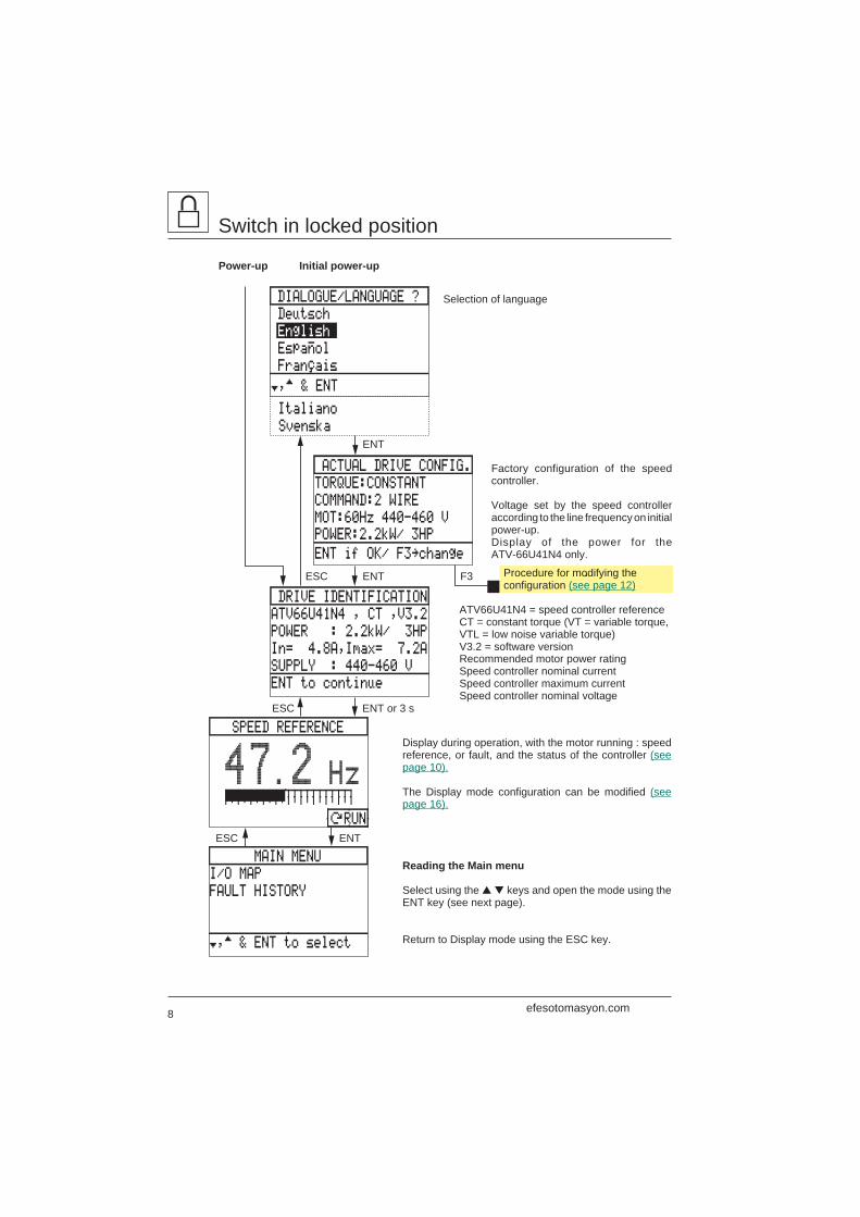
On initial power-up, or after a total return to factory settings (page 67), a message appears on thescreen for selecting the dialogue language using the ▲ and ▼ keys.
The second message displayed enables the operator to confirm or change the factory configurationof the speed controller (see page 12).
If it is not the initial power-up, the Display mode message appears in the language which haspreviously been selected. To change the language, return to the Dialogue menu using the ESCkey.
GermanEnglishSpanishFrenchItalianSwedish
Displays one or more electricaloperating values (see page 17), or afault.
Depending on the position of the accessswitch at the back of the graphicterminal, the Main menu contains 3 or6 or 11 modes which can be accessed.
Altivar 66 referenceConstant / variable torqueSoftware version (access by ▼ forsoftware IE)Rating (motor power)Speed controller nominal currentSpeed controller maximum currentSpeed controller nominal voltage
If the speed controller is fitted with anyoptions, this menu displays theidentification and the software version ofeach option (access using the ▲ ▼ keys).
This menu only appears at the initialpower-up, or after a total return to factorysettings.
See page 12.
efesotomasyon.com
5
Principle of access in the Main menu
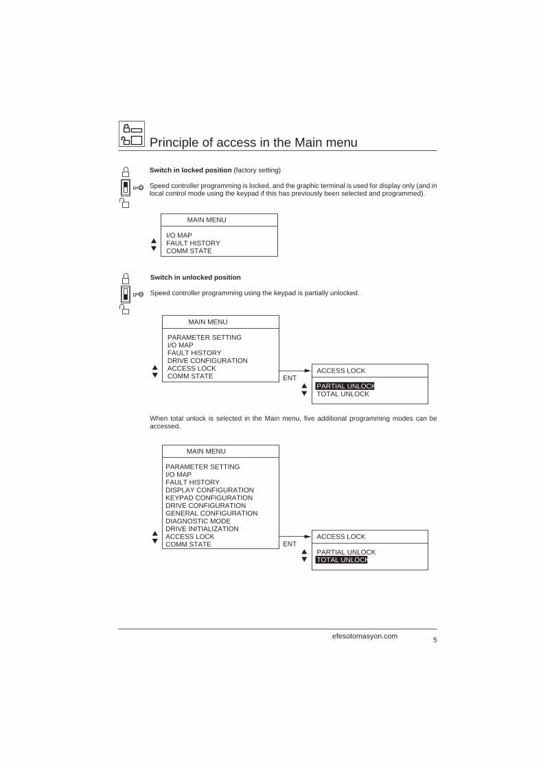
Switch in locked position (factory setting)
Speed controller programming is locked, and the graphic terminal is used for display only (and inlocal control mode using the keypad if this has previously been selected and programmed).
Switch in unlocked position
Speed controller programming using the keypad is partially unlocked.
When total unlock is selected in the Main menu, five additional programming modes can beaccessed.
MAIN MENU
I/O MAPFAULT HISTORYCOMM STATE
▲▼
MAIN MENU
PARAMETER SETTINGI/O MAPFAULT HISTORYDRIVE CONFIGURATIONACCESS LOCKCOMM STATE
ACCESS LOCK
PARTIAL UNLOCKTOTAL UNLOCK
ENT▲▼
▲▼
MAIN MENU
PARAMETER SETTINGI/O MAPFAULT HISTORYDISPLAY CONFIGURATION KEYPAD CONFIGURATION DRIVE CONFIGURATION GENERAL CONFIGURATION DIAGNOSTIC MODEDRIVE INITIALIZATIONACCESS LOCKCOMM STATE
ACCESS LOCK
PARTIAL UNLOCKTOTAL UNLOCK
ENT▲▼
▲▼
efesotomasyon.com
6
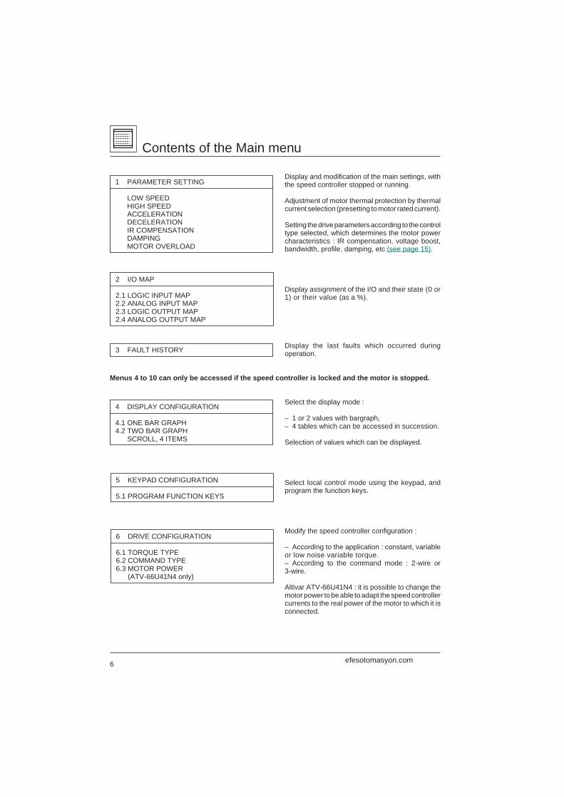
Contents of the Main menu
Display and modification of the main settings, withthe speed controller stopped or running.
Adjustment of motor thermal protection by thermalcurrent selection (presetting to motor rated current).
Setting the drive parameters according to the controltype selected, which determines the motor powercharacteristics : IR compensation, voltage boost,bandwidth, profile, damping, etc (see page 15).
Display assignment of the I/O and their state (0 or1) or their value (as a %).
Display the last faults which occurred duringoperation.
Menus 4 to 10 can only be accessed if the speed controller is locked and the motor is stopped.
Select the display mode :
– 1 or 2 values with bargraph,– 4 tables which can be accessed in succession.
Selection of values which can be displayed.
Select local control mode using the keypad, andprogram the function keys.
Modify the speed controller configuration :
– According to the application : constant, variableor low noise variable torque.– According to the command mode : 2-wire or3-wire.
Altivar ATV-66U41N4 : it is possible to change themotor power to be able to adapt the speed controllercurrents to the real power of the motor to which it isconnected.
6 DRIVE CONFIGURATION
6.1 TORQUE TYPE6.2 COMMAND TYPE6.3 MOTOR POWER
(ATV-66U41N4 only)
4 DISPLAY CONFIGURATION
4.1 ONE BAR GRAPH4.2 TWO BAR GRAPH SCROLL, 4 ITEMS
1 PARAMETER SETTING
LOW SPEED HIGH SPEED ACCELERATION DECELERATION IR COMPENSATION DAMPING MOTOR OVERLOAD
2 I/O MAP
2.1 LOGIC INPUT MAP2.2 ANALOG INPUT MAP2.3 LOGIC OUTPUT MAP2.4 ANALOG OUTPUT MAP
3 FAULT HISTORY
5 KEYPAD CONFIGURATION
5.1 PROGRAM FUNCTION KEYS
efesotomasyon.com
7
9 DRIVE INITIALIZATION
9.1 TOTAL FACTORY SETTING9.2 PARTIAL FACTORY SETTING9.3 CUSTOMER SETTING MEMORIZATION9.4 RECALL USER SETTING
GO TO MENU ?
7.11
7.1 DRIVE PARAMETERS
7.11 MOTOR PARAMETERS7.12 CONTROL PARAMETERS7.13 CONTROL TYPE
Contents of the Main menu
Modification of the general configuration of thespeed controller :
– Configuration and setting of the driveparameters.– Selection of the application functions.– Reassignment of logic and analog outputs.– Fault management.
Motor parameters : programming parametersspecific to the motor. These depend on whetherthe speed controller is configured for constant orvariable torque, and on the control type selected(see page 21).
Control parameters : modification of the speedcontroller settings by extending the adjustmentranges, modifying the ramp type, and selecting theskip frequency.
Control type : selecting the motor powercharacteristics for adapting the speed controller tothe application.
Tests the speed controller :
– Autodiagnostic : control card of transistors.– I/O test.– Testing of microprocessor and internal powersupplies ± 15 V.
Total or partial return to factory settings.
Saves the configuration and the settings to aPCMCIA card which can be installed in the speedcontroller.
Transfer of data to the speed controller from aPCMCIA card on which data was previously loaded.
Selects partial or total unlock.
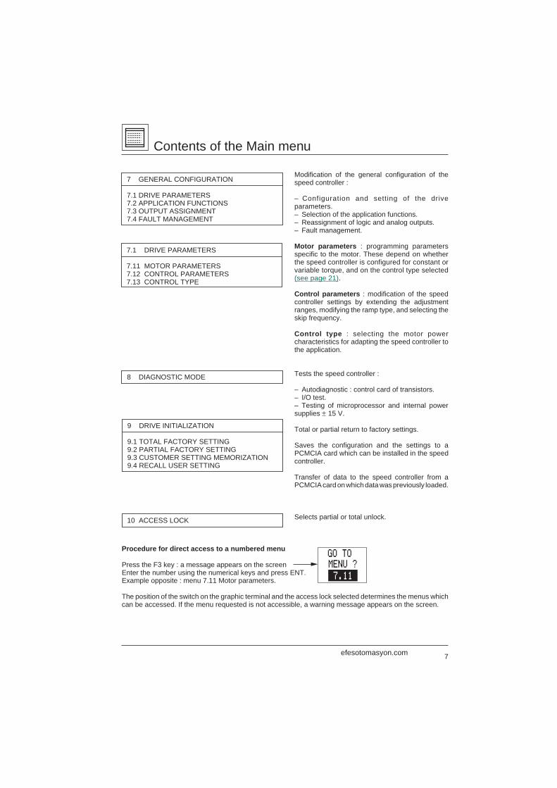
Procedure for direct access to a numbered menu
Press the F3 key : a message appears on the screenEnter the number using the numerical keys and press ENT.Example opposite : menu 7.11 Motor parameters.
The position of the switch on the graphic terminal and the access lock selected determines the menus whichcan be accessed. If the menu requested is not accessible, a warning message appears on the screen.
7 GENERAL CONFIGURATION
7.1 DRIVE PARAMETERS7.2 APPLICATION FUNCTIONS7.3 OUTPUT ASSIGNMENT7.4 FAULT MANAGEMENT
8 DIAGNOSTIC MODE
10 ACCESS LOCK
efesotomasyon.com
8
Selection of language
Switch in locked position
Power-up Initial power-up
Factory configuration of the speedcontroller.
Voltage set by the speed controlleraccording to the line frequency on initialpower-up.Display of the power for theATV-66U41N4 only.
ATV66U41N4 = speed controller referenceCT = constant torque (VT = variable torque,VTL = low noise variable torque)V3.2 = software versionRecommended motor power ratingSpeed controller nominal currentSpeed controller maximum currentSpeed controller nominal voltage
Display during operation, with the motor running : speedreference, or fault, and the status of the controller (seepage 10).
The Display mode configuration can be modified (seepage 16).
Reading the Main menu
Select using the ▲ ▼ keys and open the mode using theENT key (see next page).
Return to Display mode using the ESC key.
DRIVE IDENTIFICATION
ATV66U41N4 , CT ,V3.2
POWER : 2.2kW/ 3HP
In= 4.8A,Imax= 7.2A
SUPPLY : 440-460 V
ENT to continue
MAIN MENU
I/O MAP
FAULT HISTORY
†,™ & ENT to select
ENT
ENT
ENTESC
ESC
ACTUAL DRIVE CONFIG.
TORQUE:CONSTANT
COMMAND:2 WIRE
MOT:60Hz 440-460 V
ENT if OK/ F3‘change
POWER:2.2kW/ 3HP
F3
DIALOGUE/LANGUAGE ?
Deutsch
English
Español
†,™ & ENT
Français
Italiano
Svenska
SPEED REFERENCE
47.2 Hz
ÚRUN
ENT or 3 sESC
Procedure for modifying theconfiguration (see page 12)
efesotomasyon.com
9
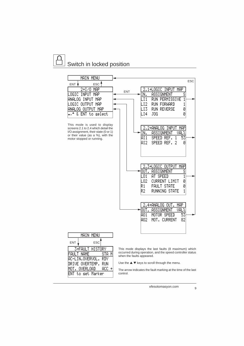
3‘FAULT HISTORY
FAULT NAME STA M
AC-LIN.OVERVOL. RDY
DRIVE OVERTEMP. RUN
MOT. OVERLOAD ACC “
ENT to set Marker
ESCENT
MAIN MENU
2‘I/O MAP
LOGIC INPUT MAP
ANALOG INPUT MAP
LOGIC OUTPUT MAP
ANALOG OUTPUT MAP
†,™ & ENT to select
2.1‘LOGIC INPUT MAP
IN. ASSIGNMENT S
LI1 RUN PERMISSIVE 1
LI2 RUN FORWARD 1
LI3 RUN REVERSE 0
LI4 JOG 0
2.2‘ANALOG INPUT MAP
IN. ASSIGNMENT VAL%
AI1 SPEED REF. 1 53
AI2 SPEED REF. 2 0
2.3‘LOGIC OUTPUT MAP
OUT. ASSIGNMENT S
LO1 AT SPEED 1
LO2 CURRENT LIMIT 0
R1 FAULT STATE 0
R2 RUNNING STATE 1
2.4‘ANALOG OUT. MAP
OUT. ASSIGNMENT VAL%
AO1 MOTOR SPEED 53
AO2 MOT. CURRENT 82
ESCENTESC
ENT
MAIN MENU
Switch in locked position
This mode is used to displayscreens 2.1 to 2.4 which detail theI/O assignment, their state (0 or 1)or their value (as a %), with themotor stopped or running.
This mode displays the last faults (8 maximum) whichoccurred during operation, and the speed controller statuswhen the faults appeared.
Use the ▲ ▼ keys to scroll through the menu.
The arrow indicates the fault marking at the time of the lastcontrol.
efesotomasyon.com
10
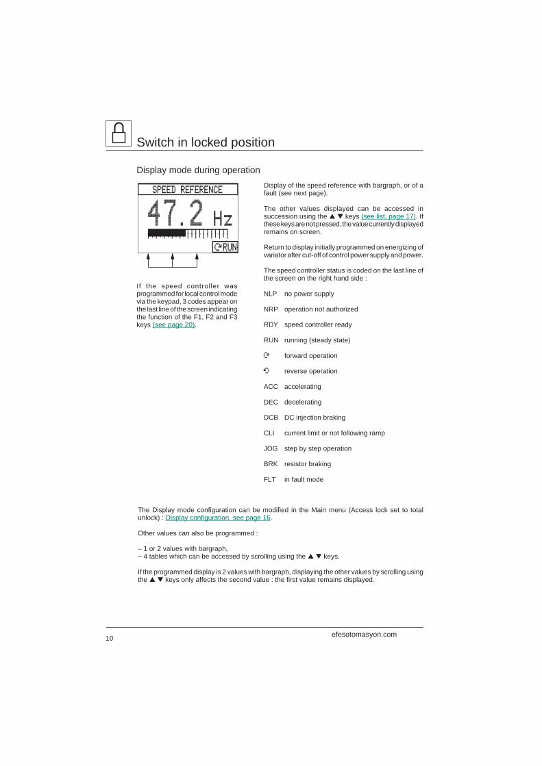
SPEED REFERENCE
47.2 Hz
ÚRUN
Switch in locked position
Display mode during operationDisplay of the speed reference with bargraph, or of afault (see next page).
The other values displayed can be accessed insuccession using the ▲ ▼ keys (see list, page 17). Ifthese keys are not pressed, the value currently displayedremains on screen.
Return to display initially programmed on energizing ofvariator after cut-off of control power supply and power.
The speed controller status is coded on the last line ofthe screen on the right hand side :
NLP no power supply
NRP operation not authorized
RDY speed controller ready
RUN running (steady state)
Ú forward operation
 reverse operation
ACC accelerating
DEC decelerating
DCB DC injection braking
CLI current limit or not following ramp
JOG step by step operation
BRK resistor braking
FLT in fault mode
The Display mode configuration can be modified in the Main menu (Access lock set to totalunlock) : Display configuration, see page 16.
Other values can also be programmed :
– 1 or 2 values with bargraph,– 4 tables which can be accessed by scrolling using the ▲ ▼ keys.
If the programmed display is 2 values with bargraph, displaying the other values by scrolling usingthe ▲ ▼ keys only affects the second value : the first value remains displayed.
If the speed controller wasprogrammed for local control modevia the keypad, 3 codes appear onthe last line of the screen indicatingthe function of the F1, F2 and F3keys (see page 20).
efesotomasyon.com
11
Switch in locked position
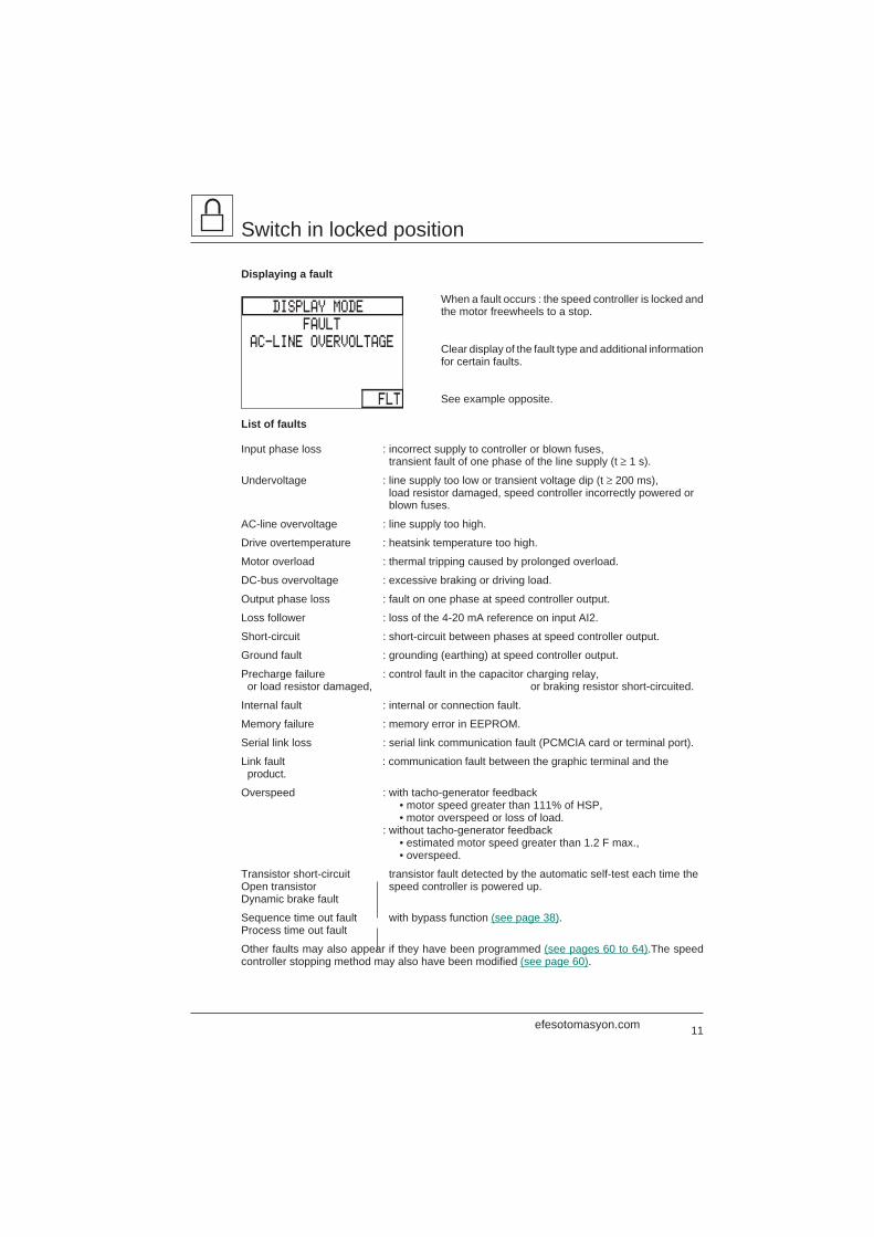
Displaying a fault
When a fault occurs : the speed controller is locked andthe motor freewheels to a stop.
Clear display of the fault type and additional informationfor certain faults.
See example opposite.
List of faults
Input phase loss : incorrect supply to controller or blown fuses, transient fault of one phase of the line supply (t ≥ 1 s).
Undervoltage : line supply too low or transient voltage dip (t ≥ 200 ms), load resistor damaged, speed controller incorrectly powered or blown fuses.
AC-line overvoltage : line supply too high.
Drive overtemperature : heatsink temperature too high.
Motor overload : thermal tripping caused by prolonged overload.
DC-bus overvoltage : excessive braking or driving load.
Output phase loss : fault on one phase at speed controller output.
Loss follower : loss of the 4-20 mA reference on input AI2.
Short-circuit : short-circuit between phases at speed controller output.
Ground fault : grounding (earthing) at speed controller output.
Precharge failure : control fault in the capacitor charging relay, or load resistor damaged, or braking resistor short-circuited.
Internal fault : internal or connection fault.
Memory failure : memory error in EEPROM.
Serial link loss : serial link communication fault (PCMCIA card or terminal port).
Link fault : communication fault between the graphic terminal and the product.
Overspeed : with tacho-generator feedback• motor speed greater than 111% of HSP,• motor overspeed or loss of load.
: without tacho-generator feedback• estimated motor speed greater than 1.2 F max.,• overspeed.
Transistor short-circuit transistor fault detected by the automatic self-test each time theOpen transistor speed controller is powered up.Dynamic brake fault
Sequence time out fault with bypass function (see page 38).Process time out fault
Other faults may also appear if they have been programmed (see pages 60 to 64).The speedcontroller stopping method may also have been modified (see page 60).
DISPLAY MODE
FAULT
AC-LINE OVERVOLTAGE
FLT
efesotomasyon.com
12
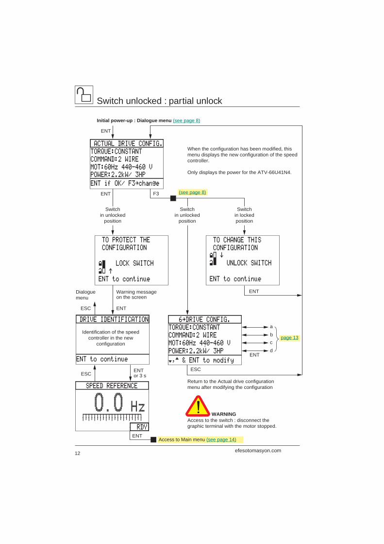
TO PROTECT THE
CONFIGURATION
‹ LOCK SWITCH
ENT to continue
› ”
TO CHANGE THIS
CONFIGURATION
› UNLOCK SWITCH
ENT to continue
‹ ’
DRIVE IDENTIFICATION 6‘DRIVE CONFIG.
TORQUE:CONSTANT
COMMAND:2 WIRE
MOT:60Hz 440-460 V
†,™ & ENT to modify
POWER:2.2kW/ 3HP
ENT
ESCENTor 3 s
Dialoguemenu
ESC ENT
Warning messageon the screen
ESC
Switchin unlocked
position
Switchin unlocked
position
Switchin lockedposition
ENT
When the configuration has been modified, thismenu displays the new configuration of the speedcontroller.
Only displays the power for the ATV-66U41N4.
ENT
ENT
ENT
Return to the Actual drive configurationmenu after modifying the configuration
WARNINGAccess to the switch : disconnect thegraphic terminal with the motor stopped.
ACTUAL DRIVE CONFIG.
TORQUE:CONSTANT
COMMAND:2 WIRE
MOT:60Hz 440-460 V
ENT if OK/ F3‘change
POWER:2.2kW/ 3HP
F3
ENT to continue
Identification of the speedcontroller in the new
configuration
SPEED REFERENCE
0.0 Hz
RDY
a
bc
d
Switch unlocked : partial unlock
Initial power-up : Dialogue menu (see page 8)
(see page 8)
page 13
Access to Main menu (see page 14)
efesotomasyon.com
13
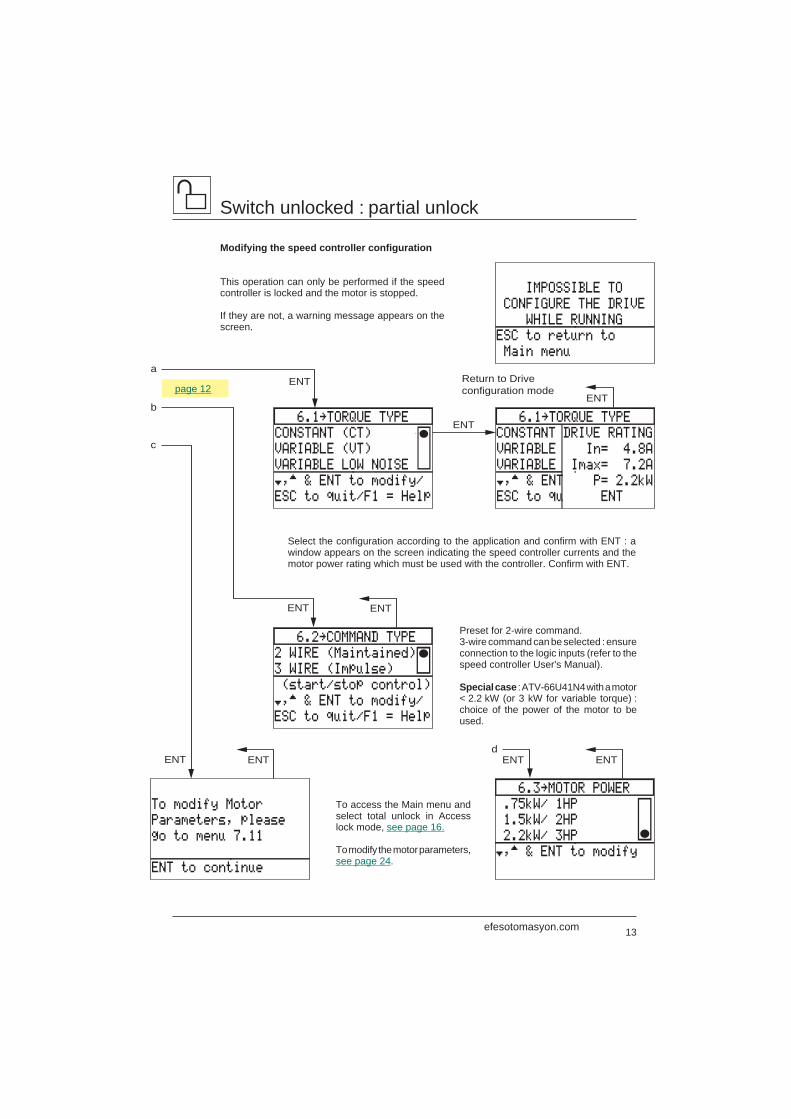
IMPOSSIBLE TO
CONFIGURE THE DRIVE
WHILE RUNNING
ESC to return to
Main menu
6.1‘TORQUE TYPE
CONSTANT (CT)
VARIABLE (VT)
VARIABLE LOW NOISE
†,™ & ENT to modify/
ESC to quit/F1 = Help
CONSTANT DRIVE RATING
VARIABLE In= 4.8A
VARIABLE Imax= 7.2A
6.1‘TORQUE TYPE
†,™ & ENT P= 2.2kW
ESC to qu ENT
6.2‘COMMAND TYPE
2 WIRE (Maintained)
3 WIRE (Impulse)
(start/stop control)
†,™ & ENT to modify/
ESC to quit/F1 = Help
To modify Motor
Parameters, please
go to menu 7.11
ENT to continue
ENT ENT
ENT ENT
ENT
Return to Driveconfiguration mode
ENT
6.3‘MOTOR POWER
.75kW/ 1HP
1.5kW/ 2HP
2.2kW/ 3HP
†,™ & ENT to modify
ENTENT
ENT
d
a
b
c
Switch unlocked : partial unlock
Modifying the speed controller configuration
This operation can only be performed if the speedcontroller is locked and the motor is stopped.
If they are not, a warning message appears on thescreen.
To access the Main menu andselect total unlock in Accesslock mode, see page 16.
To modify the motor parameters,see page 24.
Select the configuration according to the application and confirm with ENT : awindow appears on the screen indicating the speed controller currents and themotor power rating which must be used with the controller. Confirm with ENT.
Preset for 2-wire command.3-wire command can be selected : ensureconnection to the logic inputs (refer to thespeed controller User's Manual).
Special case : ATV-66U41N4 with a motor< 2.2 kW (or 3 kW for variable torque) :choice of the power of the motor to beused.
page 12
efesotomasyon.com
14
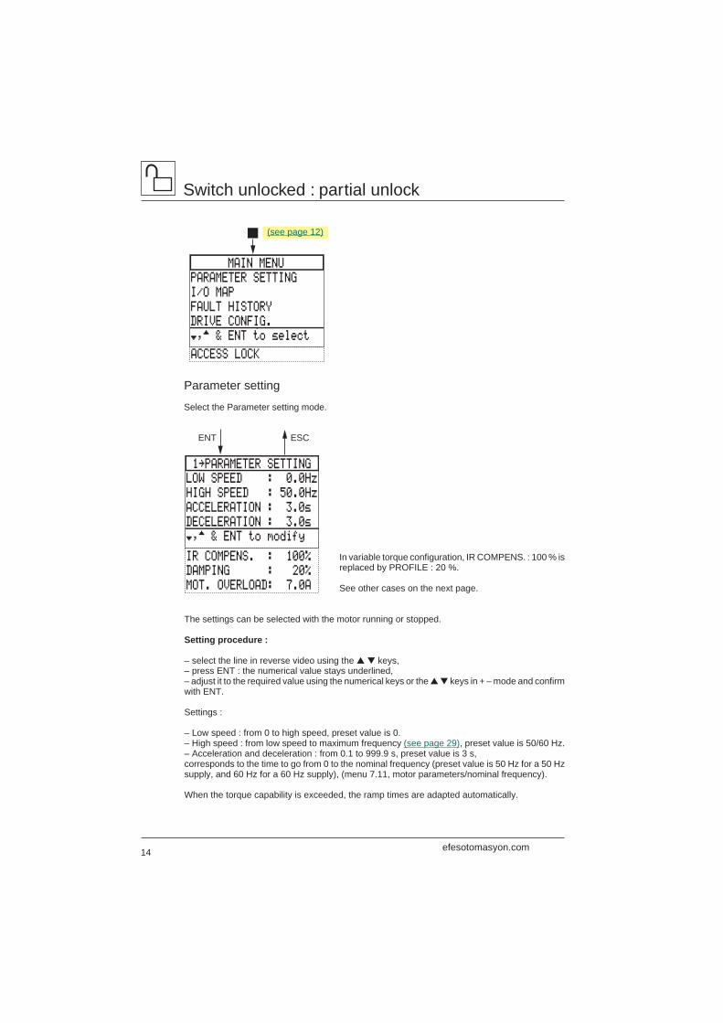
1‘PARAMETER SETTING
LOW SPEED : 0.0Hz
HIGH SPEED : 50.0Hz
ACCELERATION : 3.0s
DECELERATION : 3.0s
†,™ & ENT to modify
DAMPING : 20%
MOT. OVERLOAD: 7.0A
ENT ESC
IR COMPENS. : 100%
MAIN MENU
PARAMETER SETTING
I/O MAP
FAULT HISTORY
DRIVE CONFIG.
†,™ & ENT to select
ACCESS LOCK
Switch unlocked : partial unlock
Parameter setting
Select the Parameter setting mode.
In variable torque configuration, IR COMPENS. : 100 % isreplaced by PROFILE : 20 %.
See other cases on the next page.
The settings can be selected with the motor running or stopped.
Setting procedure :
– select the line in reverse video using the ▲ ▼ keys,– press ENT : the numerical value stays underlined,– adjust it to the required value using the numerical keys or the ▲ ▼ keys in + – mode and confirmwith ENT.
Settings :
– Low speed : from 0 to high speed, preset value is 0.– High speed : from low speed to maximum frequency (see page 29), preset value is 50/60 Hz.– Acceleration and deceleration : from 0.1 to 999.9 s, preset value is 3 s,corresponds to the time to go from 0 to the nominal frequency (preset value is 50 Hz for a 50 Hzsupply, and 60 Hz for a 60 Hz supply), (menu 7.11, motor parameters/nominal frequency).
When the torque capability is exceeded, the ramp times are adapted automatically.
(see page 12)
efesotomasyon.com
15
Switch unlocked : partial unlock
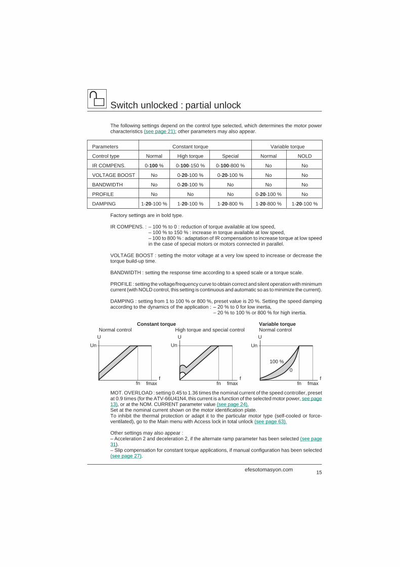
The following settings depend on the control type selected, which determines the motor powercharacteristics (see page 21); other parameters may also appear.
Parameters Constant torque Variable torque
Control type Normal High torque Special Normal NOLD
IR COMPENS. 0-100 % 0-100-150 % 0-100-800 % No No
VOLTAGE BOOST No 0-20-100 % 0-20-100 % No No
BANDWIDTH No 0-20-100 % No No No
PROFILE No No No 0-20-100 % No
DAMPING 1-20-100 % 1-20-100 % 1-20-800 % 1-20-800 % 1-20-100 %
Factory settings are in bold type.
IR COMPENS. : – 100 % to 0 : reduction of torque available at low speed,– 100 % to 150 % : increase in torque available at low speed,– 100 to 800 % : adaptation of IR compensation to increase torque at low speedin the case of special motors or motors connected in parallel.
VOLTAGE BOOST : setting the motor voltage at a very low speed to increase or decrease thetorque build-up time.
BANDWIDTH : setting the response time according to a speed scale or a torque scale.
PROFILE : setting the voltage/frequency curve to obtain correct and silent operation with minimumcurrent (with NOLD control, this setting is continuous and automatic so as to minimize the current).
DAMPING : setting from 1 to 100 % or 800 %, preset value is 20 %. Setting the speed dampingaccording to the dynamics of the application : – 20 % to 0 for low inertia,
– 20 % to 100 % or 800 % for high inertia.
Constant torque Variable torqueNormal control High torque and special control Normal control
MOT. OVERLOAD : setting 0.45 to 1.36 times the nominal current of the speed controller, presetat 0.9 times (for the ATV-66U41N4, this current is a function of the selected motor power, see page13), or at the NOM. CURRENT parameter value (see page 24).Set at the nominal current shown on the motor identification plate.To inhibit the thermal protection or adapt it to the particular motor type (self-cooled or force-ventilated), go to the Main menu with Access lock in total unlock (see page 63).
Other settings may also appear :– Acceleration 2 and deceleration 2, if the alternate ramp parameter has been selected (see page31).– Slip compensation for constant torque applications, if manual configuration has been selected(see page 27).
UUn
ffn fmax
100 %
0
UUn
ffn fmax
U
Un
ffn fmax
efesotomasyon.com
16
4‘DISPLAY CONFIG.
ONE BAR GRAPH
TWO BAR GRAPH
SCROLL, 4 ITEMS
†,™ & ENT to modify
ENT ESC
ENT
MAIN MENU
PARAMETER SETTING
I/O MAP
FAULT HISTORY
DRIVE CONFIG.
†,™ & ENT to select
ACCESS LOCK
MAIN MENU
PARAMETER SETTING
I/O MAP
FAULT HISTORY
DISPLAY CONFIG.
†,™ & ENT to select
KEYPAD CONFIG.
DRIVE CONFIG.
GENERAL CONFIG.
DIAGNOSTIC MODE
DRIVE INIT.
ACCESS LOCK
ENT or ESC
ENT
10‘ACCESS LOCK
PARTIAL UNLOCK
TOTAL UNLOCK
‹ ” For Total lock
›
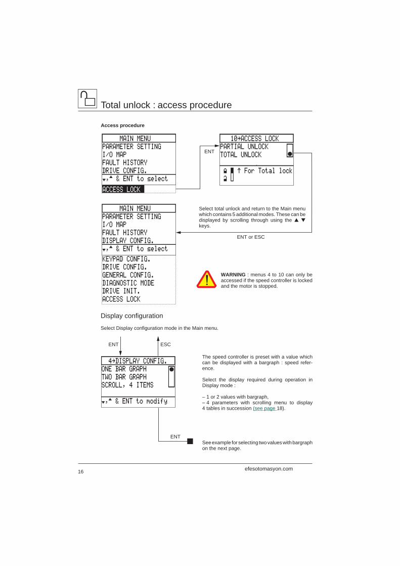
Total unlock : access procedure
Access procedure
The speed controller is preset with a value whichcan be displayed with a bargraph : speed refer-ence.
Select the display required during operation inDisplay mode :
– 1 or 2 values with bargraph,– 4 parameters with scrolling menu to display4 tables in succession (see page 18).
See example for selecting two values with bargraphon the next page.
Display configuration
Select Display configuration mode in the Main menu.
WARNING : menus 4 to 10 can only beaccessed if the speed controller is lockedand the motor is stopped.
Select total unlock and return to the Main menuwhich contains 5 additional modes. These can bedisplayed by scrolling through using the ▲ ▼keys.
efesotomasyon.com
17
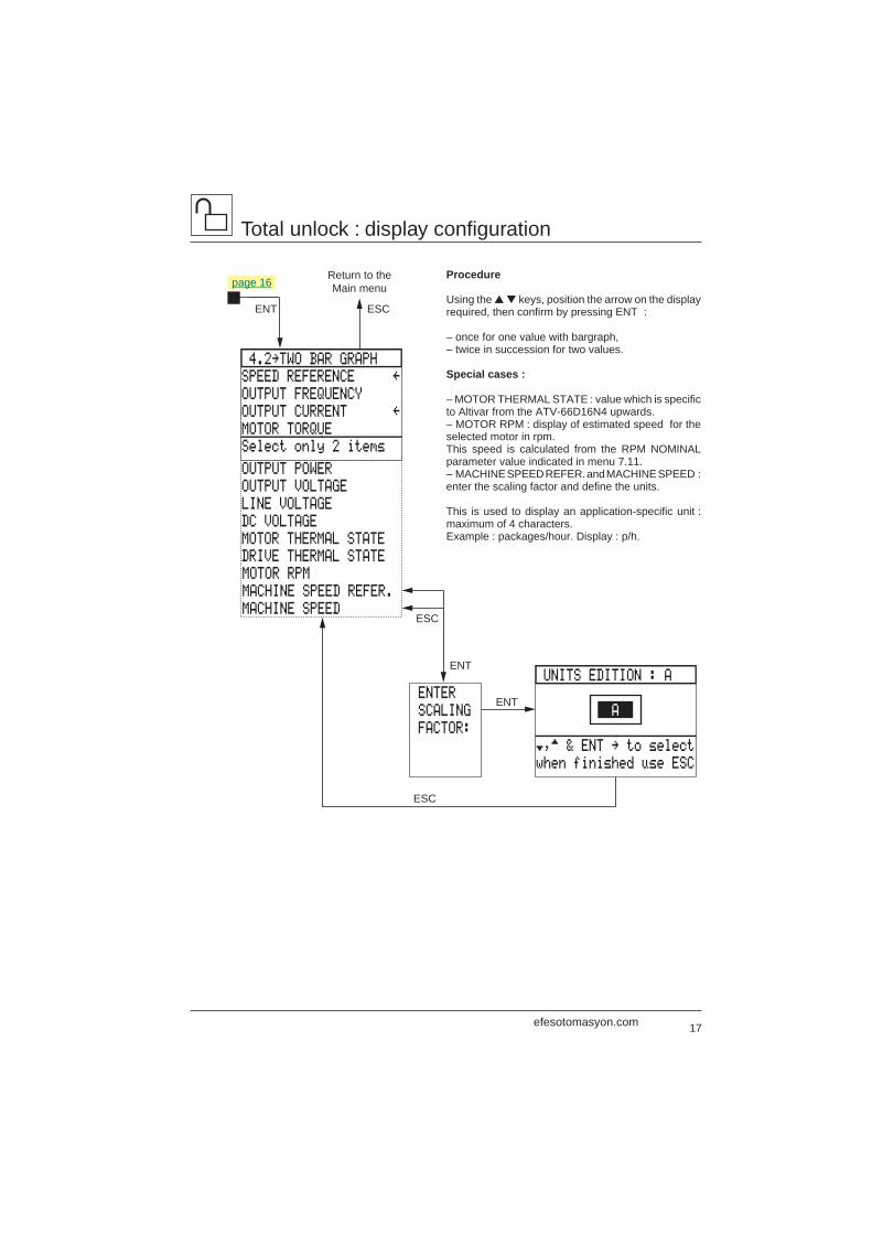
Procedure
Using the ▲ ▼ keys, position the arrow on the displayrequired, then confirm by pressing ENT :
– once for one value with bargraph,– twice in succession for two values.
Special cases :
– MOTOR THERMAL STATE : value which is specificto Altivar from the ATV-66D16N4 upwards.– MOTOR RPM : display of estimated speed for theselected motor in rpm.This speed is calculated from the RPM NOMINALparameter value indicated in menu 7.11.– MACHINE SPEED REFER. and MACHINE SPEED :enter the scaling factor and define the units.
This is used to display an application-specific unit :maximum of 4 characters.Example : packages/hour. Display : p/h.
Total unlock : display configuration
UNITS EDITION : A
†,™ & ENT ‘ to select
when finished use ESC
ENTER
SCALING
FACTOR:
4.2‘TWO BAR GRAPH
SPEED REFERENCE “
OUTPUT FREQUENCY
OUTPUT CURRENT “
MOTOR TORQUE
Select only 2 items
OUTPUT POWER
OUTPUT VOLTAGE
LINE VOLTAGE
DC VOLTAGE
MOTOR THERMAL STATE
DRIVE THERMAL STATE
MOTOR RPM
MACHINE SPEED REFER.
MACHINE SPEED
ENT ESC
ENT
ESC
ENT
ESC
Return to theMain menu
A
page 16
efesotomasyon.com
18
Total unlock : display configuration
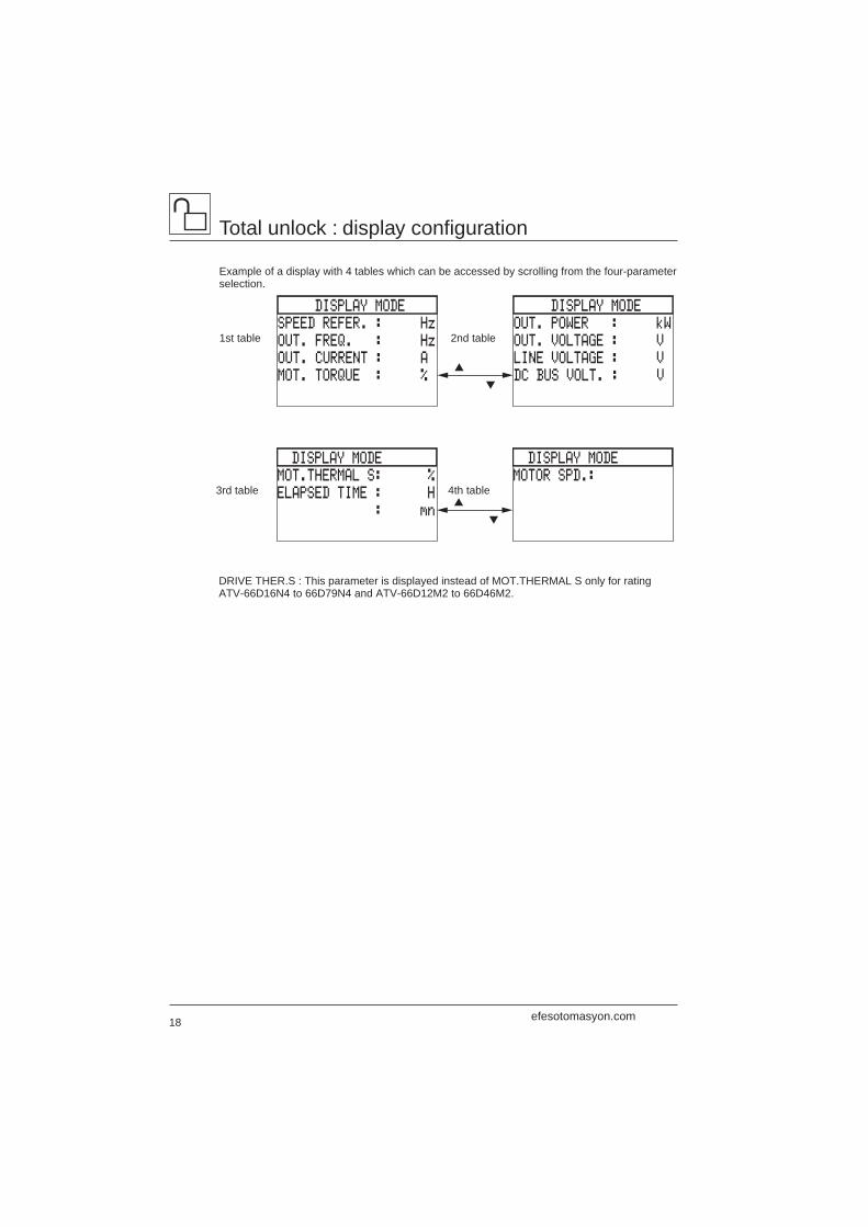
Example of a display with 4 tables which can be accessed by scrolling from the four-parameterselection.
DRIVE THER.S : This parameter is displayed instead of MOT.THERMAL S only for ratingATV-66D16N4 to 66D79N4 and ATV-66D12M2 to 66D46M2.
DISPLAY MODE
OUT. POWER : kW
OUT. VOLTAGE : V
LINE VOLTAGE : V
DC BUS VOLT. : V
DISPLAY MODE
SPEED REFER. : Hz
OUT. FREQ. : Hz
OUT. CURRENT : A
MOT. TORQUE : %▲
▼
1st table 2nd table
DISPLAY MODE
MOTOR SPD.:
DISPLAY MODE
MOT.THERMAL S: %
ELAPSED TIME : H
: mn▲
▼
3rd table 4th table
efesotomasyon.com
19
ESC
ENTER
PRESET
SPEED2:
ENTER
JOG
SPEED:
ASSIGNMENT KEY : F1
DIRECTION ÂÚ
JOG JOG
RESET FAULT RST
Select one and ENT
SCROLL SCR
PRESET SPEED 1 PS1
PRESET SPEED 2 PS2
NOT ASSIGNED ---
5.1‘PROG. FUNCT.KEYS
KEY ASSIGNMENT
F1 DIRECTION
F2 SCROLL
F3 JOG
†,™ & ENT to modify
ENT
ENTor
ESC
ENT
ENT
ENT or ESC
ENT
Return to the Main menu
ENT
5‘KEYPAD CONFIG.
TERMINAL COMMAND
TER/KEY BY LI:----
KEYPAD COMMAND
TER/KEY BY F2
PROGRAM FUNCT. KEYS
ESC
Total unlock : keypad configuration
Keypad configuration
Select Keypad configuration mode in the Main menu.
Select the required configuration, and confirm with ENT :
– TERMINAL COMMAND (factory setting) : speed controlleris controlled via the standard terminal block (refer to theUser's Manual).
– KEYPAD COMMAND : local control of the speed controllervia the keypad (in this case, it is not necessary to connectthe terminal block logic and analog inputs, except LI1 and+24 to be connected).
– Switching from terminal command to keypad commandand vice versa : from the terminal block by reassigning logicinput LI3 or LI4 (select TER/KEY BY LI) or from the keypadusing the F2 key (select TER/KEY BY F2).
To reassign a logic input, follow the instructions which aredisplayed on the screen (see example on page 27).
The PROGRAM FUNCT. KEYS menu displays the default assignments of the function keys.To change these, select the keys to be reassigned in succession (see example below).
If TER/KEY BY F2 switching is selected, the F2 key cannot be reassigned.
efesotomasyon.com
20
SPEED REFERENCE
47.2 Hz
ÚRUNÂÚ SCR JOG
Total unlock : keypad configuration
Example of the display in Display mode
Key assignment
F1 : ÂÚ
F2 : SCR
F3 : JOG
The assignment codes appear on the last line of the screen.
Using keypad command
This command mode enables the speed controller to operate independently from its logic andanalog inputs.
WARNING : check that driving the motor does not represent any danger to personnel, as the speedcontroller does not take any account of the safety devices of the machine being driven.
Starting and stopping on the motor ramp
– Start by a single press on the RUN key.– Stop by a single press on the STOP key.
Direction of movement via the key assigned to ÂÚ (F1 for example) :
Ú = forward, Â = reverse.
The selected direction of movement is underlined on the screen.Changing the direction is achieved by a single press on the appropriate key.
If no key is assigned to the direction of movement, the normal direction of rotation of the motor isforward.
Speed reference : selected using the i key, displayed using the numerical keys, confirmed bypressing ENT, and corrected using the ▲ ▼ keys.
SCR function : scrolls through the values which can be displayed in Display mode by pressing thekey assigned to the function.
JOG function : controlled by pressing the key assigned to the function; lasts for the time the keyis pressed.
RST function : resets the speed controller if it has stopped on a fault (if the fault has disappeared)by a single press on the key assigned to the function.
VP1 and VP2 functions : displays a programmed speed reference by a single press on the keyassigned to the function. Correction is possible using the ▲ ▼ keys.
Special case : the F2 key is assigned to terminal/keypad switching. The T/K code is displayed onthe screen and the selected control mode is underlined.
efesotomasyon.com
21
7.13‘CONTROL TYPE
NORMAL
NOLD
†,™ & ENT to modify
7.13‘CONTROL TYPE
NORMAL
HIGH TORQUE
†,™ & ENT to modify
SPECIAL
7.1‘DRIVE PARAMETERS
MOTOR PARAMETERS
CONTROL PARAMETERS
CONTROL TYPE: NORMAL
†,™ & ENT to modify
7‘GENERAL CONFIG.
DRIVE PARAMETERS
APPLICATION FUNC.
OUTPUT ASSIGNMENT
FAULT MANAGEMENT
†,™ & ENT to select
ENT ESC
Drive parameters menu
Constant torque
Variable torque
Total unlock : general configuration
General configuration
Select General configuration mode in the Main menu.
This mode includes 4 menus for totally changing thespeed controller configuration and settings, selectingapplication functions, assigning logic and analog outputs,and fault management.
The Motor parameters menu is used to programparameters which are specific to the motor. Its contentsdepends on whether the speed controller is configuredfor constant torque or variable torque, and on the controltype selected (see the next page).
Factory setting : NORMAL control.Speed range : 1 to 20.
When controlling a single motor, if the application requireshigher torque at very low speed and an extended speedrange (1 to 100), select HIGH TORQUE control(sensorless flux vector control).
It is possible to control special motors or motorsconnected in parallel : select SPECIAL control.
Factory setting : NORMAL control.
To operate with minimum power consumption, selectthe NOLD function.This function automatically adapts the voltage/frequencyratio to minimize the current taken by the motor.
Do not use this function if several motors are connectedin parallel. Where there is high inertia, operation couldbe unstable.
efesotomasyon.com
22
Total unlock : general configuration
Contents of the Motor parameters menu
Constant torque : NORMAL control Constant torque : HIGH TORQUE control
(*) This parameter is not displayed if the NOLDfunction is selected : automatic setting.
Constant torque : SPECIAL control Variable torque
Contents of the Control parameters menu
This menu enables modification of the speedcontroller settings with an extension of thesettings range, adjustment of the ramp type,and prevention of mechanical resonancephenomena by skip frequencies.
7.12 CONTROL PARAMETERS
MAXIMAL FREQUENCYLOW SPEEDHIGH SPEEDACCELERATIONDECELERATIONACCELERATION TYPEDECELERATION TYPEALTERNATE RAMPSKIP FREQUENCY
7.11 MOTOR PARAMETERS
NOMINAL CURRENTNOMINAL FREQUENCYNOMINAL VOLTAGERPM NOMINALIR COMPENSATION DAMPINGROTATION NORMALIZATION : ABCCURRENT LIMITSLIP COMPENSATION BRAKE SEQUENCE
7.11 MOTOR PARAMETERS
NOMINAL CURRENTNOMINAL FREQUENCYNOMINAL VOLTAGERPM NOMINALIR COMPENSATIONVOLTAGE BOOSTDAMPINGBANDWIDTHPHASE NORMALIZATION : ABCTORQUE LIMITCURRENT LIMITSLIP COMPENSATION BRAKE SEQUENCE
7.11 MOTOR PARAMETERS
NOMINAL CURRENTNOMINAL FREQUENCYNOMINAL VOLTAGERPM NOMINALIR COMPENSATION VOLTAGE BOOST DAMPINGROTATION NORMALIZATION : ABCCURRENT LIMITSLIP COMPENSATION BRAKE SEQUENCE
7.11 MOTOR PARAMETERS
NOMINAL CURRENTNOMINAL FREQUENCYNOMINAL VOLTAGERPM NOMINALPROFILE (*)DAMPINGROTATION NORMALIZATION : ABCCURRENT LIMIT
efesotomasyon.com
23
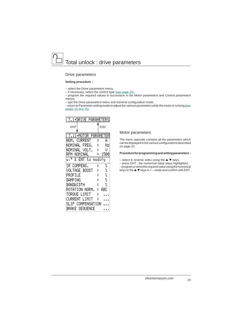
Total unlock : drive parameters
Drive parameters
Setting procedure :
– select the Drive parameters menu,– if necessary, select the control type (see page 21),– program the required values in succession in the Motor parameters and Control parametersmenus,– quit the Drive parameters menu and General configuration mode,– return to Parameter setting mode to adjust the various parameters while the motor is running (seepages 14 and 15).
Motor parameters
The menu opposite contains all the parameters whichcan be displayed in the various configurations describedon page 22.
Procedure for programming and setting parameters :
– select in reverse video using the ▲ ▼ keys,– press ENT : the numerical value stays highlighted,– program or set to the required value using the numericalkeys or the ▲ ▼ keys in + – mode and confirm with ENT.
ESCENT
7.11‘MOTOR PARAMETER
NOM. CURRENT : A
NOMINAL FREQ. : Hz
NOMINAL VOLT. : VRPM NOMINAL : 1500
IR COMPENS. : %
†,™ & ENT to modify
VOLTAGE BOOST : %
PROFILE : %
DAMPING : %
BANDWIDTH : %
ROTATION NORM. : ABC
TORQUE LIMIT : ...
CURRENT LIMIT : ...
SLIP COMPENSATION ...
BRAKE SEQUENCE ...
7.1‘DRIVE PARAMETERS
efesotomasyon.com
24
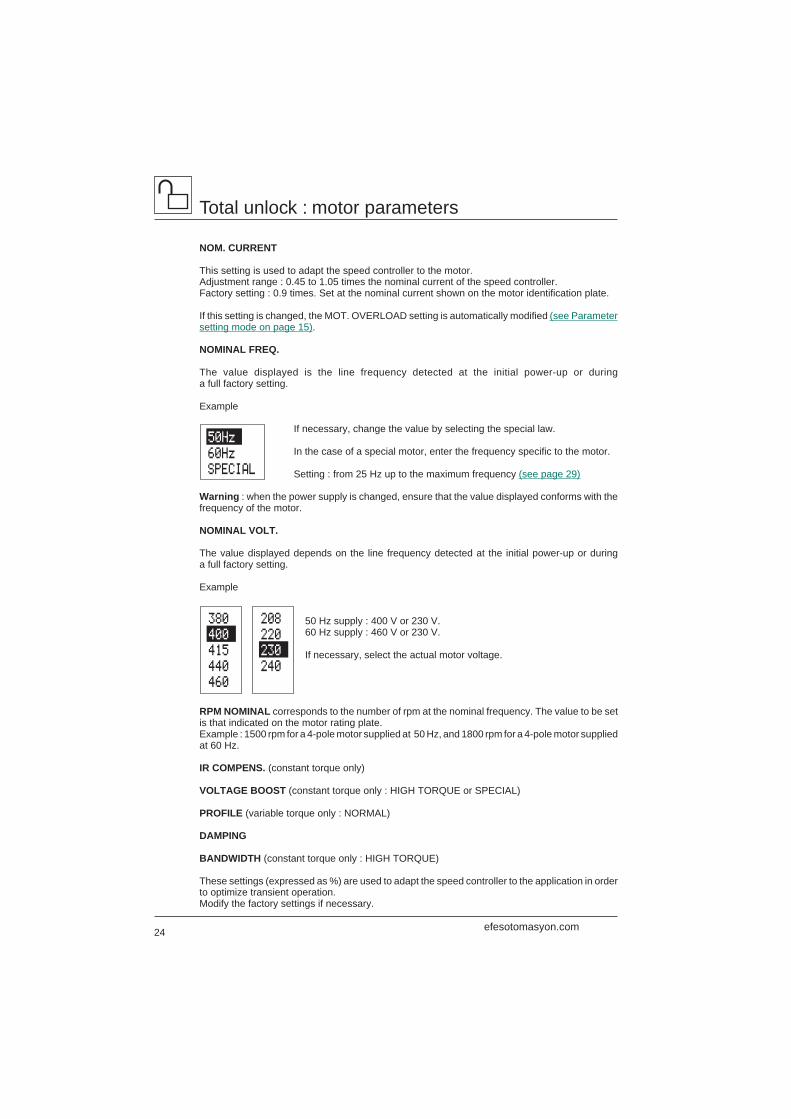
380
400
415
440
460
208
220
230
240
50Hz
60Hz
SPECIAL
Total unlock : motor parameters
NOM. CURRENT
This setting is used to adapt the speed controller to the motor.Adjustment range : 0.45 to 1.05 times the nominal current of the speed controller.Factory setting : 0.9 times. Set at the nominal current shown on the motor identification plate.
If this setting is changed, the MOT. OVERLOAD setting is automatically modified (see Parametersetting mode on page 15).
NOMINAL FREQ.
The value displayed is the line frequency detected at the initial power-up or duringa full factory setting.
Example
If necessary, change the value by selecting the special law.
In the case of a special motor, enter the frequency specific to the motor.
Setting : from 25 Hz up to the maximum frequency (see page 29)
Warning : when the power supply is changed, ensure that the value displayed conforms with thefrequency of the motor.
NOMINAL VOLT.
The value displayed depends on the line frequency detected at the initial power-up or duringa full factory setting.
Example
50 Hz supply : 400 V or 230 V.60 Hz supply : 460 V or 230 V.
If necessary, select the actual motor voltage.
RPM NOMINAL corresponds to the number of rpm at the nominal frequency. The value to be setis that indicated on the motor rating plate.Example : 1500 rpm for a 4-pole motor supplied at 50 Hz, and 1800 rpm for a 4-pole motor suppliedat 60 Hz.
IR COMPENS. (constant torque only)
VOLTAGE BOOST (constant torque only : HIGH TORQUE or SPECIAL)
PROFILE (variable torque only : NORMAL)
DAMPING
BANDWIDTH (constant torque only : HIGH TORQUE)
These settings (expressed as %) are used to adapt the speed controller to the application in orderto optimize transient operation.Modify the factory settings if necessary.
efesotomasyon.com
25
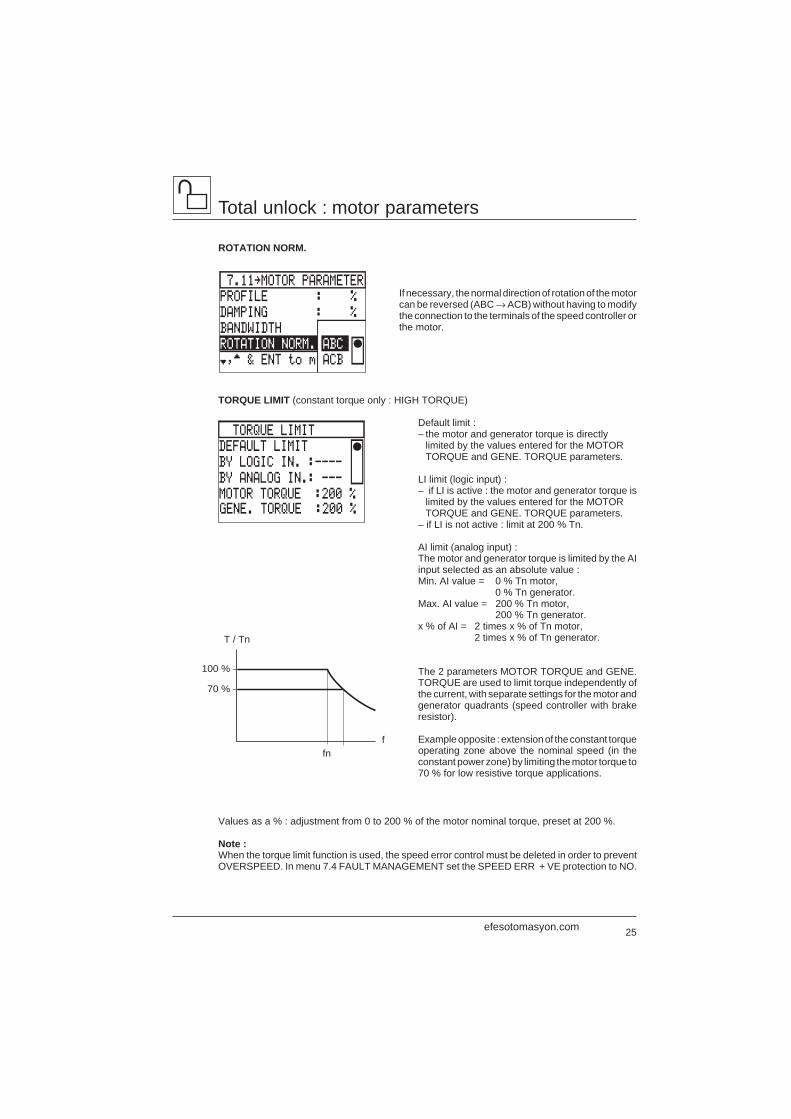
7.11‘MOTOR PARAMETER
PROFILE : %
DAMPING : %
BANDWIDTH
ROTATION NORM. ABC
†,™ & ENT to m ACB
Total unlock : motor parameters
ROTATION NORM.
If necessary, the normal direction of rotation of the motorcan be reversed (ABC → ACB) without having to modifythe connection to the terminals of the speed controller orthe motor.
TORQUE LIMIT (constant torque only : HIGH TORQUE)
Default limit :– the motor and generator torque is directly
limited by the values entered for the MOTORTORQUE and GENE. TORQUE parameters.
LI limit (logic input) :– if LI is active : the motor and generator torque is
limited by the values entered for the MOTORTORQUE and GENE. TORQUE parameters.
– if LI is not active : limit at 200 % Tn.
AI limit (analog input) :The motor and generator torque is limited by the AIinput selected as an absolute value :Min. AI value = 0 % Tn motor,
0 % Tn generator.Max. AI value = 200 % Tn motor,
200 % Tn generator.x % of AI = 2 times x % of Tn motor,
2 times x % of Tn generator.
The 2 parameters MOTOR TORQUE and GENE.TORQUE are used to limit torque independently ofthe current, with separate settings for the motor andgenerator quadrants (speed controller with brakeresistor).
Example opposite : extension of the constant torqueoperating zone above the nominal speed (in theconstant power zone) by limiting the motor torque to70 % for low resistive torque applications.
T / Tn
100 %
70 %
fnf
Values as a % : adjustment from 0 to 200 % of the motor nominal torque, preset at 200 %.
Note :When the torque limit function is used, the speed error control must be deleted in order to preventOVERSPEED. In menu 7.4 FAULT MANAGEMENT set the SPEED ERR + VE protection to NO.
TORQUE LIMIT
DEFAULT LIMIT
BY LOGIC IN. :----
BY ANALOG IN.: ---
MOTOR TORQUE :200 %GENE. TORQUE :200 %
efesotomasyon.com
26
Total unlock : motor parameters
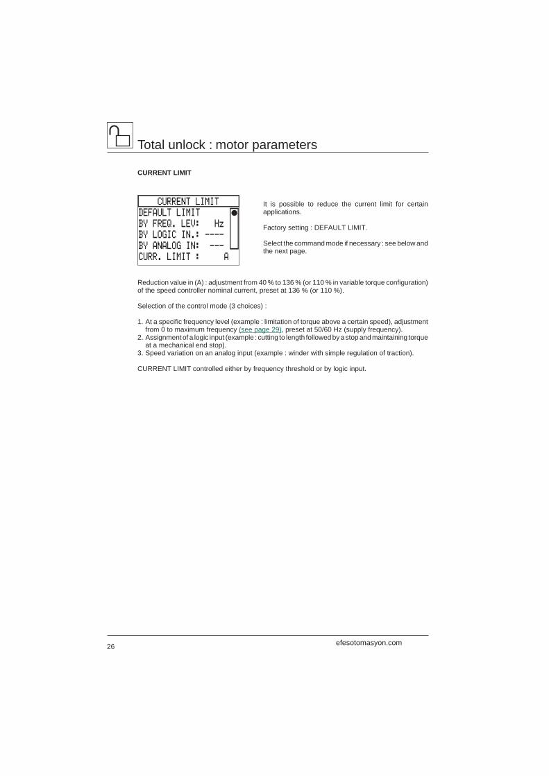
CURRENT LIMIT
It is possible to reduce the current limit for certainapplications.
Factory setting : DEFAULT LIMIT.
Select the command mode if necessary : see below andthe next page.
Reduction value in (A) : adjustment from 40 % to 136 % (or 110 % in variable torque configuration)of the speed controller nominal current, preset at 136 % (or 110 %).
Selection of the control mode (3 choices) :
1. At a specific frequency level (example : limitation of torque above a certain speed), adjustmentfrom 0 to maximum frequency (see page 29), preset at 50/60 Hz (supply frequency).
2. Assignment of a logic input (example : cutting to length followed by a stop and maintaining torqueat a mechanical end stop).
3. Speed variation on an analog input (example : winder with simple regulation of traction).
CURRENT LIMIT controlled either by frequency threshold or by logic input.
CURRENT LIMIT
DEFAULT LIMIT
BY FREQ. LEV: Hz
BY LOGIC IN.: ----
BY ANALOG IN: ---
CURR. LIMIT : A
efesotomasyon.com
27
SLIP COMPENSATION
NO
AUTOMATIC
MANUAL : Hz
(0.1 ‘ 10 Hz)
REASSIGN ?
AI2 SPEED REF. 2
’
AI2 CURRENT LIMIT
ENT to confirm
ESC to abort
CURRENT LIMIT ‘AI?
AI1 SPEED REF. 1
AI2 SPEED REF. 2
CLEAR ASSIGNMENT
Select input & ENT
ENT
ESC
ESC
ENT
ENT
0-20 mA
4-20 mA
20-4 mA
X-20 mA,X= 4.0 mA
AI2 SIGNAL TYPE
†,™ & ENT to select
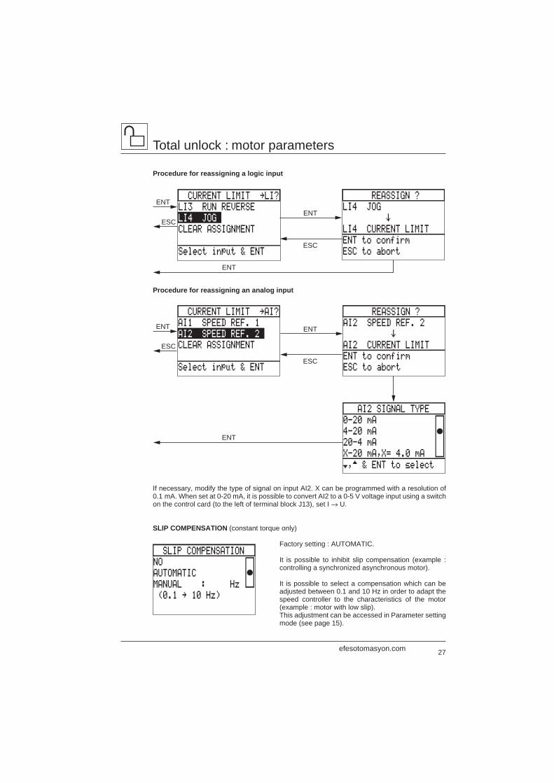
SLIP COMPENSATION (constant torque only)
Factory setting : AUTOMATIC.
It is possible to inhibit slip compensation (example :controlling a synchronized asynchronous motor).
It is possible to select a compensation which can beadjusted between 0.1 and 10 Hz in order to adapt thespeed controller to the characteristics of the motor(example : motor with low slip).This adjustment can be accessed in Parameter settingmode (see page 15).
Total unlock : motor parameters
Procedure for reassigning a logic input
Procedure for reassigning an analog input
If necessary, modify the type of signal on input AI2. X can be programmed with a resolution of0.1 mA. When set at 0-20 mA, it is possible to convert AI2 to a 0-5 V voltage input using a switchon the control card (to the left of terminal block J13), set I → U.
REASSIGN ?
LI4 JOG
’
LI4 CURRENT LIMIT
ENT to confirm
ESC to abort
CURRENT LIMIT ‘LI?
LI3 RUN REVERSE
LI4 JOG
CLEAR ASSIGNMENT
Select input & ENT
ESC
ENTENT
ESC
ENT
efesotomasyon.com
28
Total unlock : motor parameters
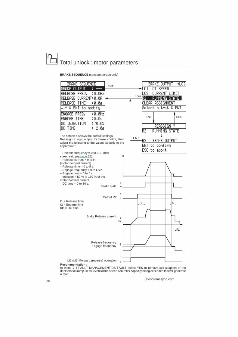
BRAKE SEQUENCE (constant torque only)
The screen displays the default settings.Reassign a logic output for brake control, thenadjust the following to the values specific to theapplication :
– Release frequency = 0 to LSP (lowspeed set, see page 14).– Release current = 0 to In(motor nominal current).– Release time = 0 to 5 s.– Engage frequency = 0 to LSP.– Engage time = 0 to 5 s.– Injection = 50 % to 150 % of themotor nominal current.– DC time = 0 to 30 s.
REASSIGN ?
R2 RUNNING STATE
’
R2 BRAKE OUTPUT
ENT to confirm
ESC to abort
ENT
ESC
BRAKE OUTPUT ‘LO?
LO1 AT SPEED
LO2 CURRENT LIMIT
R2 RUNNING STATE
CLEAR ASSIGNMENT
Select output & ENT
BRAKE SEQUENCE
BRAKE OUTPUT : ---
RELEASE FREQ. :0.0Hz
RELEASE CURRENT:0.0A
RELEASE TIME :0.0s
†,™ & ENT to modify
ENGAGE FREQ. :0.0Hz
ENGAGE TIME :0.0s
DC INJECTION :70.0%
DC TIME : 2.0s
ESCENT
ENT
Brake Release current
Output R2
Brake state1
1
0
N
1
0
t
t
t
t
t
t
IdcIl
frfl
t2
tdcf
I t1
0
Release frequencyEngage frequency
LI2 (LI3) Forward (reverse) operation
t1 = Release timet2 = Engage timetdc = DC time
Recommendation :In menu 7.4 FAULT MANAGEMENT/DB FAULT select YES to remove self-adaption of thedeceleration ramp. In the event of the speed controller capacity being exceeded this will generatea fault.
efesotomasyon.com
29
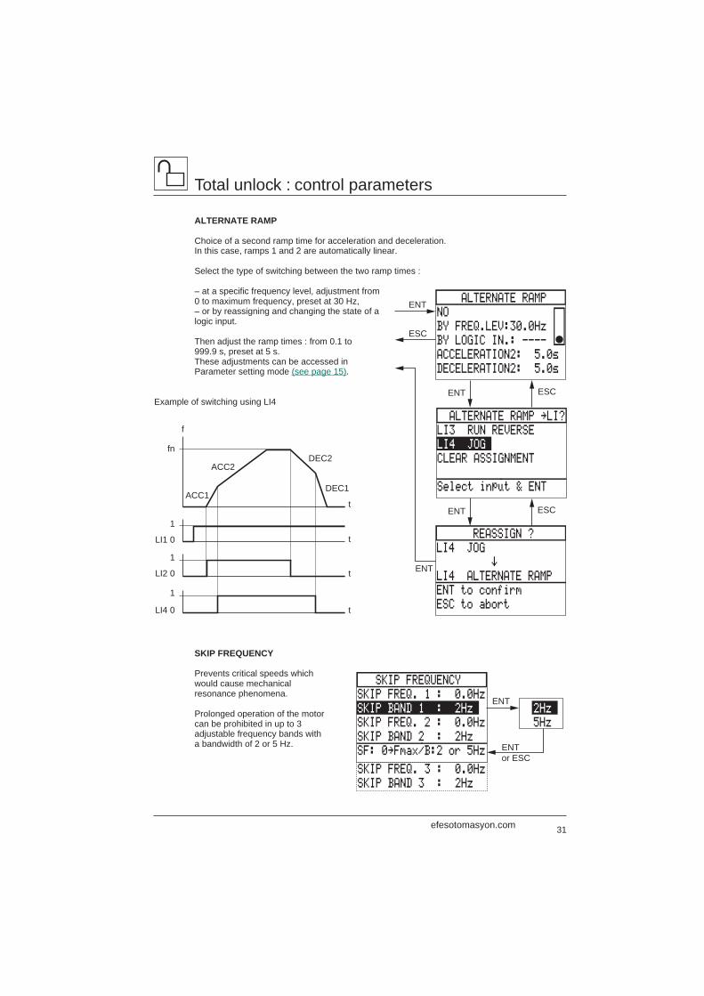
7.12‘CONTROL PARAM.
MAX.FREQUENCY: 60.0Hz
LOW SPEED : 0.0Hz
HIGH SPEED : 50.0Hz
ACCELERATION : 3.0s
†,™ & ENT to modify
DECELERATION : 3.0s
ACCEL. TYPE : LINEAR
DECEL. TYPE : LINEAR
ALTERNATE RAMP ...
SKIP FREQUENCY ...
ESCENT
Total unlock : control parameters
Control parameters
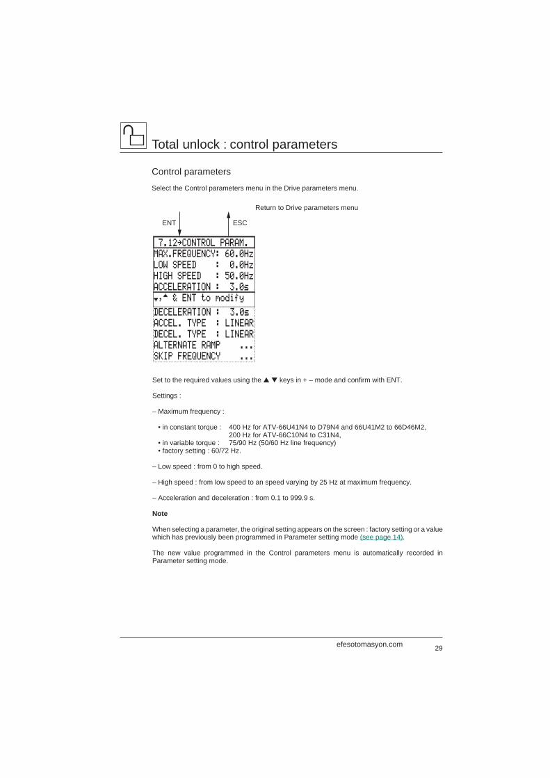
Select the Control parameters menu in the Drive parameters menu.
Return to Drive parameters menu
Set to the required values using the ▲ ▼ keys in + – mode and confirm with ENT.
Settings :
– Maximum frequency :
• in constant torque : 400 Hz for ATV-66U41N4 to D79N4 and 66U41M2 to 66D46M2, 200 Hz for ATV-66C10N4 to C31N4,
• in variable torque : 75/90 Hz (50/60 Hz line frequency) • factory setting : 60/72 Hz.
– Low speed : from 0 to high speed.
– High speed : from low speed to an speed varying by 25 Hz at maximum frequency.
– Acceleration and deceleration : from 0.1 to 999.9 s.
Note
When selecting a parameter, the original setting appears on the screen : factory setting or a valuewhich has previously been programmed in Parameter setting mode (see page 14).
The new value programmed in the Control parameters menu is automatically recorded inParameter setting mode.
efesotomasyon.com
30
DECEL. TYPE
LINEAR
S,Round Fact: 20 %
Linear Part : 3.0s
U,Round Fact: 50 %
Select and set value
ACCEL. TYPE
LINEAR
S,Round Fact: 20 %
Linear Part : 3.0s
U,Round Fact: 50 %
Select and set value
Total unlock : control parameters
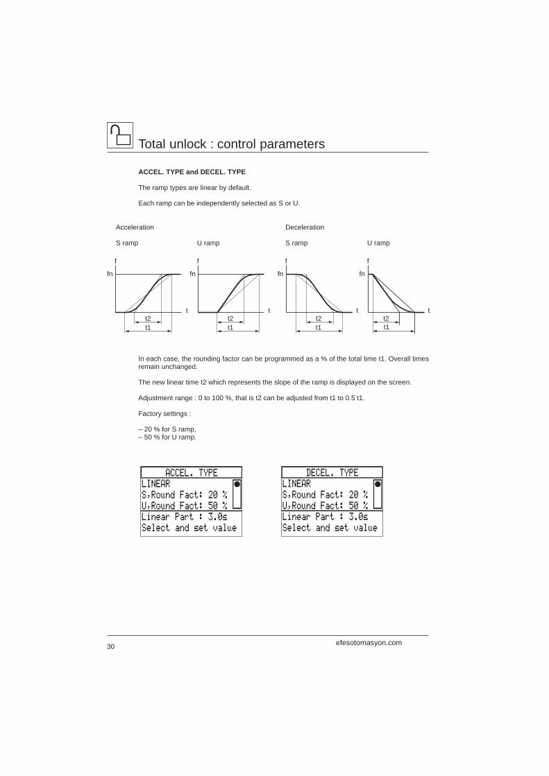
ACCEL. TYPE and DECEL. TYPE
The ramp types are linear by default.
Each ramp can be independently selected as S or U.
Acceleration
S ramp U ramp
Deceleration
S ramp U ramp
f
t2t1
t
f
t2t1
t
f
t2t1
t
f
t
t1
fn fn fn fn
t2
In each case, the rounding factor can be programmed as a % of the total time t1. Overall timesremain unchanged.
The new linear time t2 which represents the slope of the ramp is displayed on the screen.
Adjustment range : 0 to 100 %, that is t2 can be adjusted from t1 to 0.5 t1.
Factory settings :
– 20 % for S ramp,– 50 % for U ramp.
efesotomasyon.com
31
ESCENT
SKIP FREQUENCY
SKIP FREQ. 1 : 0.0Hz
SKIP BAND 1 : 2Hz
SKIP FREQ. 2 : 0.0Hz
SKIP BAND 2 : 2Hz
SF: 0‘Fmax/B:2 or 5Hz
SKIP BAND 3 : 2Hz
SKIP FREQ. 3 : 0.0Hz
REASSIGN ?
LI4 JOG
’
LI4 ALTERNATE RAMP
ENT to confirm
ESC to abort
ALTERNATE RAMP ‘LI?
LI3 RUN REVERSE
LI4 JOG
CLEAR ASSIGNMENT
Select input & ENT
ALTERNATE RAMP
NO
BY FREQ.LEV:30.0Hz
BY LOGIC IN.: ----
ACCELERATION2: 5.0s
DECELERATION2: 5.0s
ESCENT
2Hz
5Hz
ENT
ENTor ESC
ENT
ENT
ESC
Total unlock : control parameters
ALTERNATE RAMP
Choice of a second ramp time for acceleration and deceleration.In this case, ramps 1 and 2 are automatically linear.
Select the type of switching between the two ramp times :
– at a specific frequency level, adjustment from0 to maximum frequency, preset at 30 Hz,– or by reassigning and changing the state of alogic input.
Then adjust the ramp times : from 0.1 to999.9 s, preset at 5 s.These adjustments can be accessed inParameter setting mode (see page 15).
Example of switching using LI4
SKIP FREQUENCY
Prevents critical speeds whichwould cause mechanicalresonance phenomena.
Prolonged operation of the motorcan be prohibited in up to 3adjustable frequency bands witha bandwidth of 2 or 5 Hz.
f
1
LI1 0
LI2 0
LI4 0
1
1
t
t
t
t
fn
ACC1
ACC2DEC2
DEC1
efesotomasyon.com
32
Total unlock : application functions
Application functions
Select the Application functions menu in the General configuration mode.
A number of application functions can be selected usingthis menu.
The three arrows indicate the factory settings :
– RUN REVERSE (input LI3),– JOG (input LI4),– SPEED REFERENCE.
The selection of functions is limited by :
– the number of reassignable logic inputs LI on thespeed controller,
– the incompatibility of certain functions with each other,or with the selection of the brake sequence, in the caseof constant torque configuration.
Inputs and outputs necessary for selecting functions
Application functions LI inputs AI inputs LO or R2 outputs
Run reverse 1JOG (step by step) 1+/– speed 2Set point memory 1Preset speeds 1 or 2Speed reference 0 1 or 2Auto / manual 1 or 2Controlled stop 0 or 1Shutdown 0 1Terminal / keypad (1) 0 or 1Bypass 2 1Switch mot. sel./Par. 1 or 2 1 or 2PI regulator 1 or 2
(1) This function is selected in the Keypad configuration mode (see page 19).
ESCENT
7.2‘APPLIC.FUNCTIONS
RUN REVERSE “
JOG “
+/- SPEED
SET POINT MEMORY
†,™ & ENT to select
PRESET SPEEDS
SHUTDOWNBYPASS
SPEED REFERENCE “
SWITCH MOT.SEL./PAR.PI REGULATOR
AUTO/MANUAL
CONTROLLED STOP
efesotomasyon.com
33
Total unlock : application functions
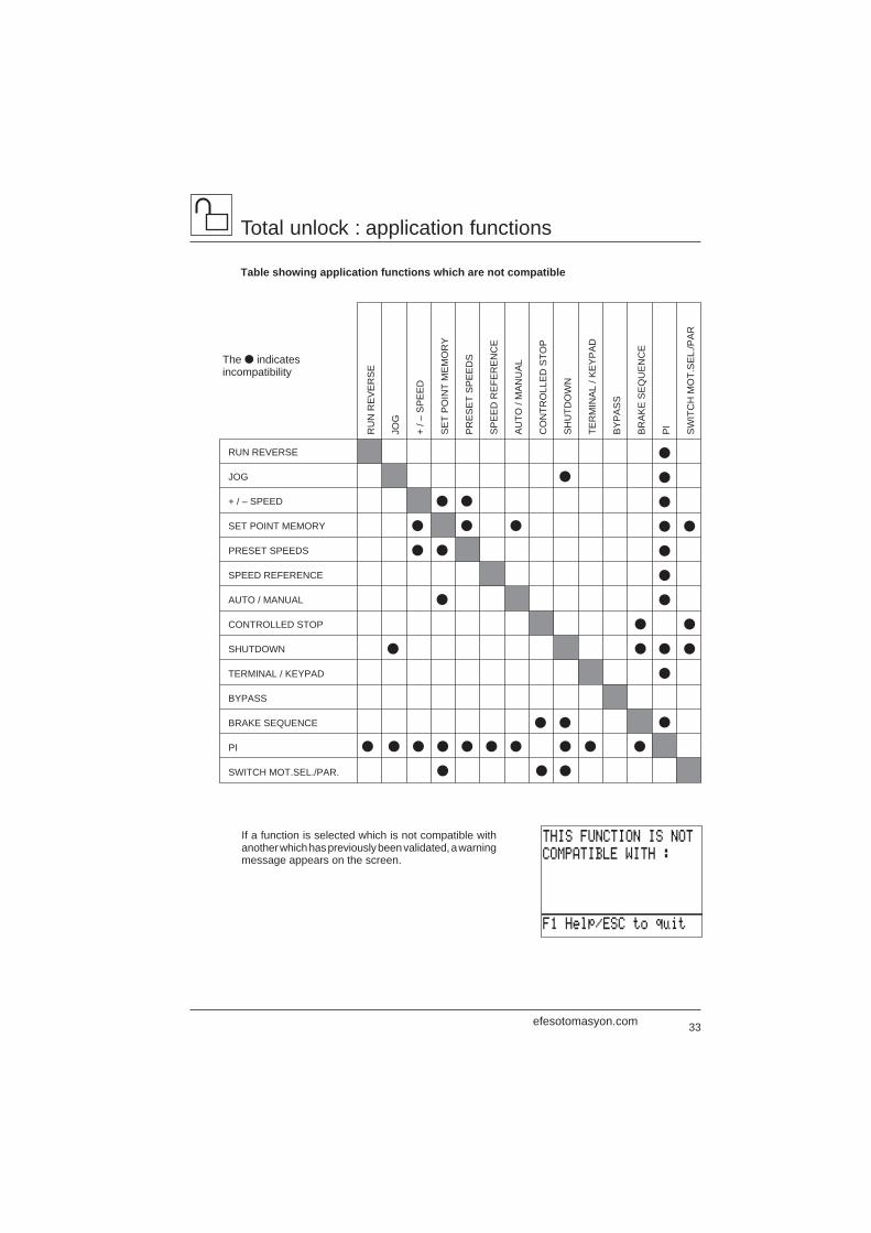
Table showing application functions which are not compatible
If a function is selected which is not compatible withanother which has previously been validated, a warningmessage appears on the screen.
The ● indicatesincompatibility
THIS FUNCTION IS NOT
COMPATIBLE WITH :
F1 Help/ESC to quit
●
●
●
●
●
●
●
● ● ● ● ● ● ● ●
● ●●
● ●
●
●
● ●
●
●
●
●
●
●
●
●
●
●
●
●
●
●
●
●
RUN REVERSE
JOG
+ / – SPEED
SET POINT MEMORY
PRESET SPEEDS
SPEED REFERENCE
AUTO / MANUAL
CONTROLLED STOP
SHUTDOWN
TERMINAL / KEYPAD
BYPASS
BRAKE SEQUENCE
PI
SWITCH MOT.SEL./PAR.
RU
N R
EV
ER
SE
JOG
+ / –
SP
EE
D
SE
T P
OIN
T M
EM
OR
Y
PR
ES
ET
SP
EE
DS
SP
EE
D R
EFE
RE
NC
E
AU
TO /
MA
NU
AL
CO
NTR
OLL
ED
STO
P
SH
UTD
OW
N
TER
MIN
AL
/ KE
YP
AD
BY
PA
SS
BR
AK
E S
EQ
UE
NC
E
PI
SW
ITC
H M
OT.
SE
L./P
AR
efesotomasyon.com
34
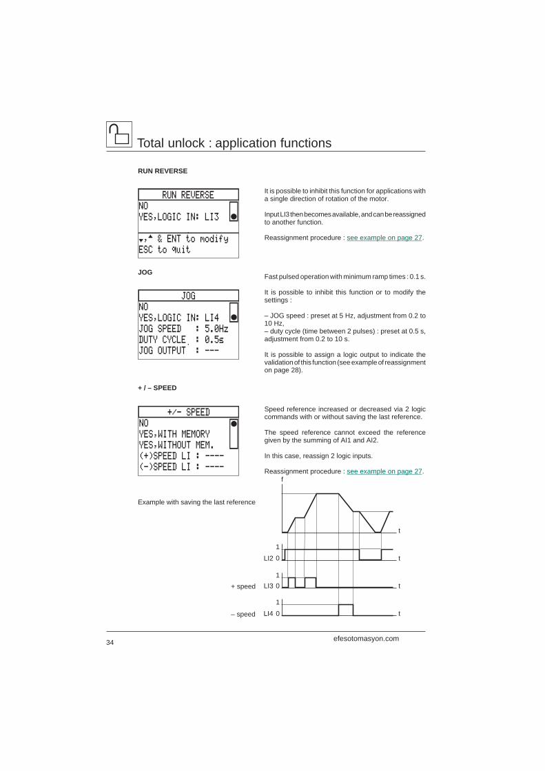
+/- SPEED
NO
YES,WITH MEMORY
YES,WITHOUT MEM.
(+)SPEED LI : ----
(-)SPEED LI : ----
JOG
NO
YES,LOGIC IN: LI4
JOG SPEED : 5.0Hz
DUTY CYCLE : 0.5s
JOG OUTPUT : ---
RUN REVERSE
NO
YES,LOGIC IN: LI3
†,™ & ENT to modify
ESC to quit
Total unlock : application functions
RUN REVERSE
JOG
It is possible to inhibit this function for applications witha single direction of rotation of the motor.
Input LI3 then becomes available, and can be reassignedto another function.
Reassignment procedure : see example on page 27.
Fast pulsed operation with minimum ramp times : 0.1 s.
It is possible to inhibit this function or to modify thesettings :
– JOG speed : preset at 5 Hz, adjustment from 0.2 to10 Hz,– duty cycle (time between 2 pulses) : preset at 0.5 s,adjustment from 0.2 to 10 s.
It is possible to assign a logic output to indicate thevalidation of this function (see example of reassignmenton page 28).
Speed reference increased or decreased via 2 logiccommands with or without saving the last reference.
The speed reference cannot exceed the referencegiven by the summing of AI1 and AI2.
In this case, reassign 2 logic inputs.
Reassignment procedure : see example on page 27.
+ / – SPEED
LI4 01
10LI3
10
t
t
t
t
f
LI2
– speed
+ speed
Example with saving the last reference
efesotomasyon.com
35
3 PRESET SPEEDS
LOGIC INPUT a: ----
LOGIC INPUT b: ----
SPEED 1 : 5.0Hz
SPEED 2 : 10.0Hz
Enter all values ‘ESC
1 PRESET SPEED
LOGIC INPUT a: ----
SPEED 1 : 5.0Hz
Enter all values ‘ESC
NO
1 PRESET SPEED
3 PRESET SPEEDS
PRESET SPEEDS
SPEED 3 : 15.0Hz
SET POINT MEMORY
NO
YES,LOGIC IN: ----
†,™ & ENT to modify
ESC to quit
Total unlock : application functions
Reassignment of logic inputs : follow the procedure described on page 26.
f
1LI2 0
1LI4 0
0.1 s 0.1 s 0.1 s
t
t
t
FrequencyReference
SET POINT MEMORY
Example of controlvia input LI4
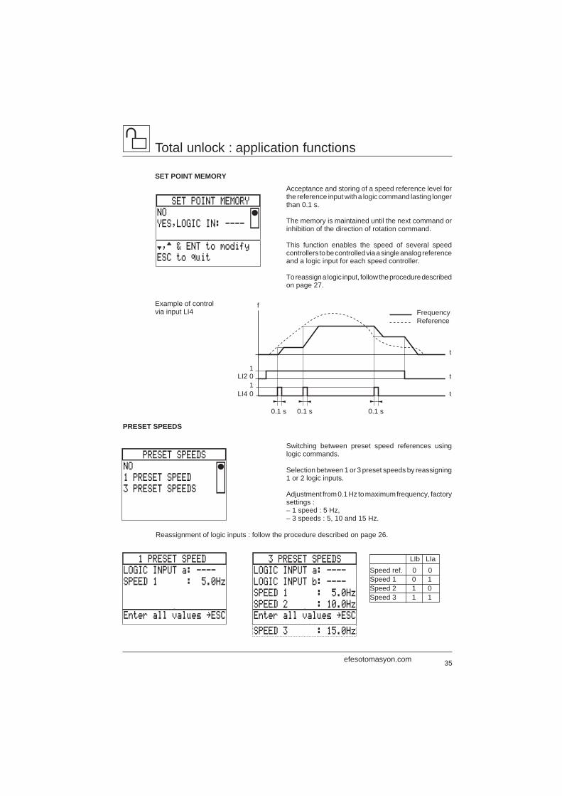
Acceptance and storing of a speed reference level forthe reference input with a logic command lasting longerthan 0.1 s.
The memory is maintained until the next command orinhibition of the direction of rotation command.
This function enables the speed of several speedcontrollers to be controlled via a single analog referenceand a logic input for each speed controller.
To reassign a logic input, follow the procedure describedon page 27.
Switching between preset speed references usinglogic commands.
Selection between 1 or 3 preset speeds by reassigning1 or 2 logic inputs.
Adjustment from 0.1 Hz to maximum frequency, factorysettings :– 1 speed : 5 Hz,– 3 speeds : 5, 10 and 15 Hz.
PRESET SPEEDS
LIb LIaSpeed ref. 0 0Speed 1 0 1Speed 2 1 0Speed 3 1 1
efesotomasyon.com
36
AUTO/MANUAL
NO
YES,LOGIC IN:
†,™ & ENT to modify
ESC to quit
AUTO RUN LI : ----
SPEED REFERENCE
SPEED REF. 1 : AI1
SPEED REF. 2 : AI2
CLAMP SUM : YES
†,™ & ENT to modify
0-20 mA
4-20 mA
20-4 mA
X-20 mA,X= 4.0 mA
AI2 SIGNAL TYPE
MULTIPLY BY (-1): NO
NO
YESENT
Clamping the sum :
– YES (factory setting) : if AI1 – AI2 is zero or negative, the result is low speed,– NO : if AI1 – AI2 is negative, the direction of rotation is reversed.
Switching 2 analog references by logic command.
This function avoids switching low-level signals, andmakes the 2 inputs speed reference 1 and speedreference 2 independent.
Local manual control by speed reference 1.
Automatic control by a process controller (or PLC) onspeed reference 2, enabled by the logic input at state 1.Program AI2 according to the PID controller character-istics in the Speed reference function (see above).
The 3rd line AUTO RUN LI appears on the screen if thefunction is selected, and offers the possibility ofreassigning a logic input to control the run commandvia the PID controller in automatic mode, while inputLI2 is inactive in AUTO position. This function is op-tional, and not essential for the application.
Reassignment procedure : see example on page 27.
Example opposite : run command given automaticallyby the process controller on input LI3.
Total unlock : application functions
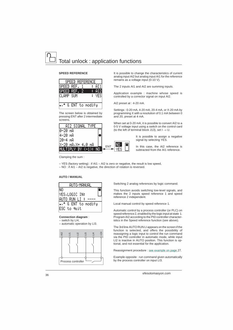
It is possible to change the characteristics of currentanalog input AI2 but analog input AI1 for the referenceremains as a voltage input (0-10 V).
The 2 inputs AI1 and AI2 are summing inputs.
Application example : machine whose speed iscontrolled by a corrector signal on input AI2.
AI2 preset at : 4-20 mA.
Settings : 0-20 mA, 4-20 mA, 20-4 mA, or X-20 mA byprogramming X with a resolution of 0.1 mA between 0and 20, preset at 4 mA.
When set at 0-20 mA, it is possible to convert AI2 to a0-5 V voltage input using a switch on the control card(to the left of terminal block J13), set I → U.
It is possible to assign a negativesignal by selecting YES.
In this case, the AI2 reference issubtracted from the AI1 reference.
Connection diagram :– switch by LI4,– automatic operation by LI3.
SPEED REFERENCE
The screen below is obtained bypressing ENT after 2 intermediatescreens.
AUTO / MANUAL
AI2
LI1
LI2
LI3
LI4
+24
Process controller
efesotomasyon.com
37
CONT. STOP BY LI
LOGIC INPUT : ----
ACTIVE STATE : LOW
STOP TYPE : FREEW
Enter all values ‘ESC
ENT
ENT
LOW
HIGH
FREEWHEEL
FAST
DC-INJ.: 70%
DC-TIME: 2.0s
CONTROLLED STOP
NO
BY FREQUENCY LEVEL
BY LOGIC INPUT
BY LI / FREQ.LEVEL
†,™ & ENT to modify
Selecting the stop command :
– by reassigning a logic input,– by a specific frequency level,– or by using both these commands.
In each case, there are three stopping methods :
– “Freewheel” stop : locks the speed controller andstops the motor according to the inertia and the resistivetorque.– Fast stop : braking with minimum acceptabledeceleration ramp time without locking on a fault.– Adjustable DC injection braking.
Reassign a logic input : see example on page 27.Control by logic input
Select the stoppingmethod.
For DC injection,adjust the values.
Adjust the level : from 50 % to 150 % of the nominal motor current, preset at 70 %.Adjust the time : from 0 to 30 s, preset at 2 s.Other possibility : set the time at 30.1 s.In this case, braking is permanent with an injection level programmed during the first 30 s and at50 % for the remainder of the time.
Total unlock : application functions
CONTROLLED STOP
Select the state of the input :active at low (0) or high (1),preset at low.
CONT.STOP LI&FREQ.L.
LOGIC INPUT : ----
ACTIVE STATE : LOW
STOP TYPE : FREEW
FREQ. LEVEL : 0.0Hz
STOP TYPE : FREEW
CONT.STOP BY FREQ.L.
FREQ. LEVEL : 0.0Hz
STOP TYPE : FREEW
Enter all values ‘ESC
Control by frequency levelSet at the required frequency level.
Adjustment range : from 0 to the maximum frequency.
Select the stopping method (see above).
When a shutdown request is made, the controlledshutdown type that is selected will be activated as soonas the motor frequency drops below the threshold value.
Control by logic input and frequency levelReassign, select and set as shown above.
Operation is as follows :
– at the initial stop command, the stopping methodwhich corresponds to this command is validated,– if the other stop command is given, the stoppingmethod which corresponds to this command is onlyvalidated if it has priority over the first (priority :"freewheel", fast, DC injection).
efesotomasyon.com
38
ENT ESC
BYPASS I/O
SEQUENCE INPUT :----
PROCESS INPUT :----
RUN OUT.COMMAND :----
Enter all values ‘ESC
BYPASS
NO
YES,DEFINE I/O
DECAY TIME : 2.0s
SEQUENCE Tof : 5.0s
PROCESS Tof : 60.0s
SHUTDOWN
NO
YES
LOGIC OUTPUT : ---
DWELL TIME : 1.0s
†,™ & ENT to modify
Total unlock : application functions
SHUTDOWN Low speed maintained for an adjustable time between0.1 and 60 s : preset at 1 s.
Indicates the end of low speed operation by the changein state of a logic output.
Application example : pumping station with monitoringvalve closing before the pump stops completely.
Reassign a logic output (see example on page 28), andset the dwell time.
Example with LO1
BYPASS This function can be used :
– either to isolate the motor when there is no run command,using a contactor between the speed controller and themotor : see the next page,– or to supply the motor by direct connection to the linesupply (see pages 40 and 41).
Reassign 2 logic inputs :
– LI4 for SEQUENCE INPUT,– LI3 for PROCESS INPUT (if necessary).
Reassign relay output R2 for RUN OUT. COMMAND.
Set the values according to the application :
– DECAY TIME (motor demagnetization) : adjust from0.2 to 10 s, preset at 2 s,– SEQUENCE Tof (dwell time to be set above theenergization time of KM2) : adjust from 0.2 to 300 s,preset at 5 s,– PROCESS Tof (optional dwell time to be set, see page41) : adjust from 0.2 to 300 s, preset at 60 s.
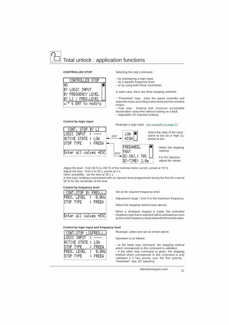
Dwell time
t
t
t
LS
1LI2 0
1LO1 0
N
Comment : a run command given duringthe dwell time will only be enabled at theend of low speed operation.
efesotomasyon.com
39
KM2
T1
F3
F2 F4
A1
U/T
1
V/T
2
W/T
3
L1 L2 L3 A1 A1R
2C
LI3
LI2
LI1
LI4 +2
4
R2A
M1 3 c
U1
W1
V1
KM2 KM2
Q1
Total unlock : application functions
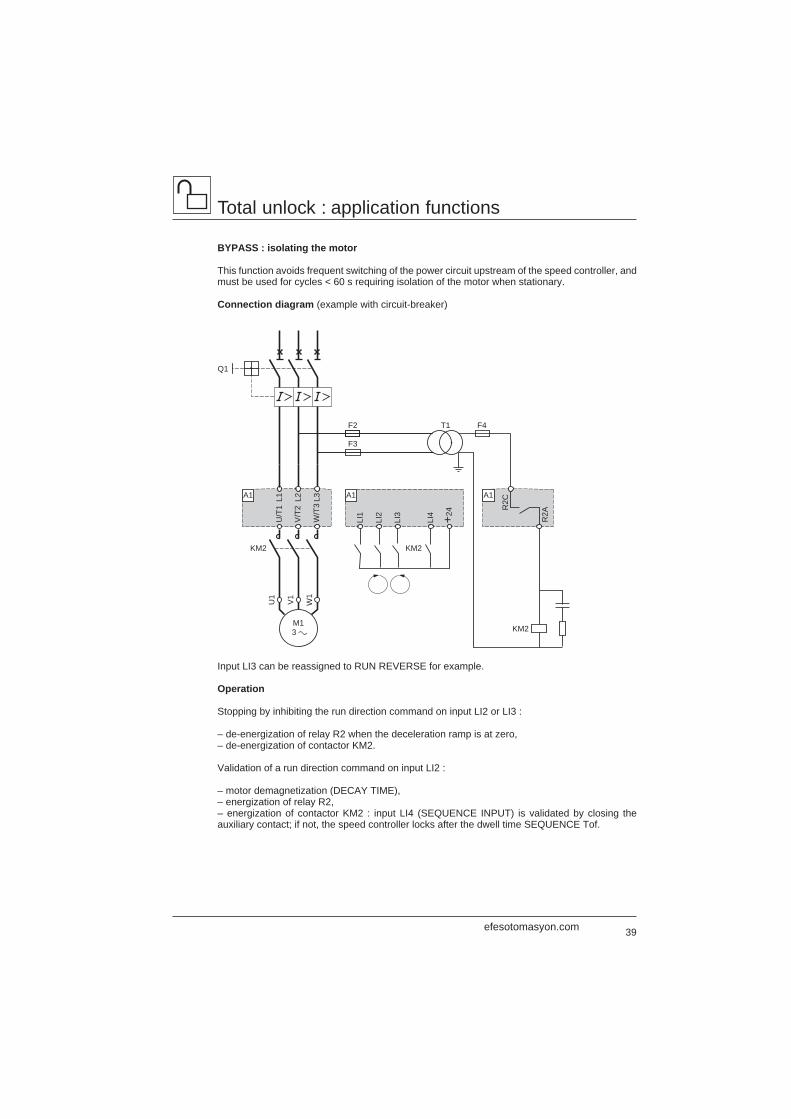
BYPASS : isolating the motor
This function avoids frequent switching of the power circuit upstream of the speed controller, andmust be used for cycles < 60 s requiring isolation of the motor when stationary.
Connection diagram (example with circuit-breaker)
Input LI3 can be reassigned to RUN REVERSE for example.
Operation
Stopping by inhibiting the run direction command on input LI2 or LI3 :
– de-energization of relay R2 when the deceleration ramp is at zero,– de-energization of contactor KM2.
Validation of a run direction command on input LI2 :
– motor demagnetization (DECAY TIME),– energization of relay R2,– energization of contactor KM2 : input LI4 (SEQUENCE INPUT) is validated by closing theauxiliary contact; if not, the speed controller locks after the dwell time SEQUENCE Tof.
efesotomasyon.com
40
T1
F3
F2 F4
A1
U/T
1
V/T
2
W/T
3
L1 L2 L3 A1
CL1
CL2
LI3
LI2
LI1
LI4 +2
4 F1
KM3
Q1
KM1
M1 3 c
U1
W1
V1
KM2 KM2
Total unlock : application functions
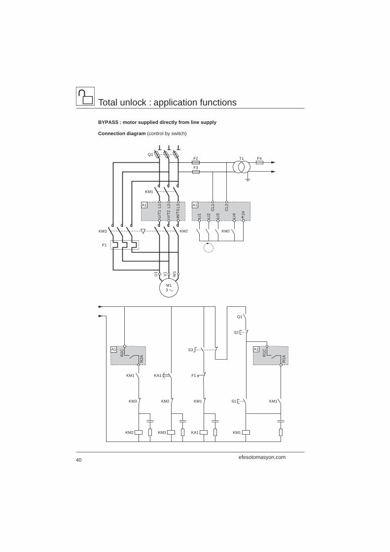
BYPASS : motor supplied directly from line supply
Connection diagram (control by switch)
KM2
KM1 F1
S3
S2
S1
KA1
A1
R2C
R2A
A1
R1C
R1A
KM3
KM3
KM2
KA1
KM1
Q1
KM1
KM1
efesotomasyon.com
41
Total unlock : application functions
Operation
The motor is connected directly to the line supply in the event of a speed controller fault :
– manual control via switch S3,– de-energization of contactors KM1 and KM2 : isolates the speed controller power,– dwell time of auxiliary contactor KA1 : demagnetizes the motor,– energization of contactor KM3.
After the fault has disappeared, the motor power supply can be reconnected by the speed controller(this can be performed without the need for a prior stop request) :
– manual control via switch S3,– de-energization of contactor KM3,– manual control via pushbutton S1,– energization of contactor KM1 : supplying power to the speed controller,– enabling of run commands on inputs LI1 and LI2,– motor demagnetization (DECAY TIME),– energization of relay R2,– energization of contactor KM2 : input LI4 (SEQUENCE INPUT) is enabled by closing the auxiliarycontact; if not, the speed controller locks after the dwell time SEQUENCE Tof,– if necessary, validate input LI3 (PROCESS INPUT) by closing a load detection contact; if not, thespeed controller locks after the dwell time PROCESS Tof (example : checking flow rate or pressurein a pumping station).
Other possibilities :
– Start on a ramp up to nominal frequency, then direct connection to the line supply.– Reconnection of supply via the speed controller for controlled deceleration.
Applications : conveyor systems, starting several motors in cascade.
WARNING : when the BYPASS function is selected, the “motor phase fault” is no longer taken intoconsideration.
Note :Motor parameters are measured when the speed controller is powered up.If the motor is present on power-up : the measured parameters are used.If the motor is missing on power-up : tabulated parameters or the last parameters measured areused.For maximum performance when the motor is electrically isolated from the speed controller onpower-up, an initialization sequence (motor connected to the speed controller on power-up) mustbe performed in order to measure and memorize the motor parameters at least once.This sequence will result in optimal performance.If this initialization sequence is not performed, the speed controller will operate using parametersfrom standard motors memorized in the speed controller.
efesotomasyon.com
42
Total unlock : application functions
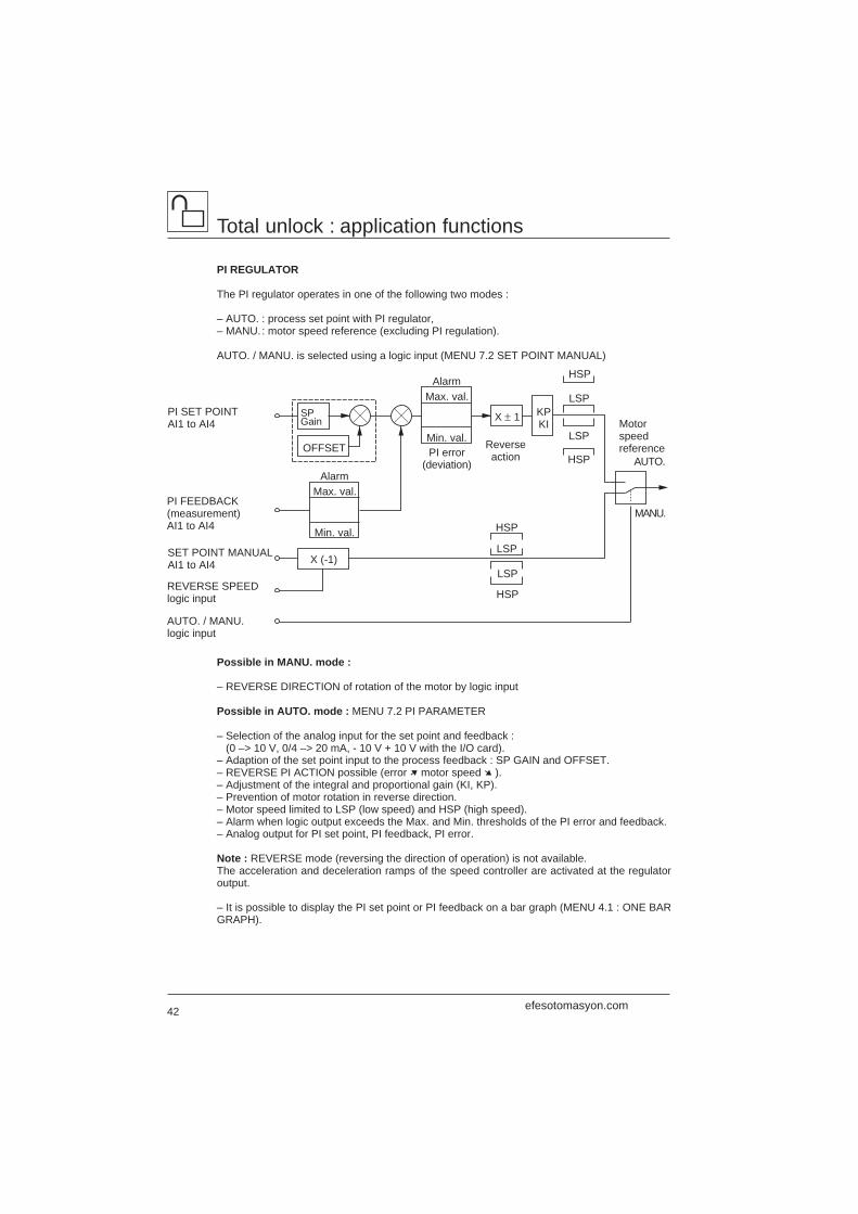
PI REGULATOR
The PI regulator operates in one of the following two modes :
– AUTO. : process set point with PI regulator,– MANU.: motor speed reference (excluding PI regulation).
AUTO. / MANU. is selected using a logic input (MENU 7.2 SET POINT MANUAL)
Possible in MANU. mode :
– REVERSE DIRECTION of rotation of the motor by logic input
Possible in AUTO. mode : MENU 7.2 PI PARAMETER
– Selection of the analog input for the set point and feedback : (0 –> 10 V, 0/4 –> 20 mA, - 10 V + 10 V with the I/O card).– Adaption of the set point input to the process feedback : SP GAIN and OFFSET.– REVERSE PI ACTION possible (error ➚ motor speed ➘ ).– Adjustment of the integral and proportional gain (KI, KP).– Prevention of motor rotation in reverse direction.– Motor speed limited to LSP (low speed) and HSP (high speed).– Alarm when logic output exceeds the Max. and Min. thresholds of the PI error and feedback.– Analog output for PI set point, PI feedback, PI error.
Note : REVERSE mode (reversing the direction of operation) is not available.The acceleration and deceleration ramps of the speed controller are activated at the regulatoroutput.
– It is possible to display the PI set point or PI feedback on a bar graph (MENU 4.1 : ONE BARGRAPH).
X (-1)
Min. val.
Max. val.Alarm
SET POINT MANUALAI1 to AI4
PI SET POINTAI1 to AI4
OFFSET
X ± 1 Motorspeedreference
HSP
LSP
LSP
HSP
KPKI
ReverseactionPI error
(deviation)
Min. val.
Max. val.Alarm
HSP
HSP
LSP
LSP
PI FEEDBACK(measurement)AI1 to AI4
REVERSE SPEEDlogic input
AUTO. / MANU.logic input
AUTO.
MANU.
SPGain
efesotomasyon.com
43
Total unlock : application functions
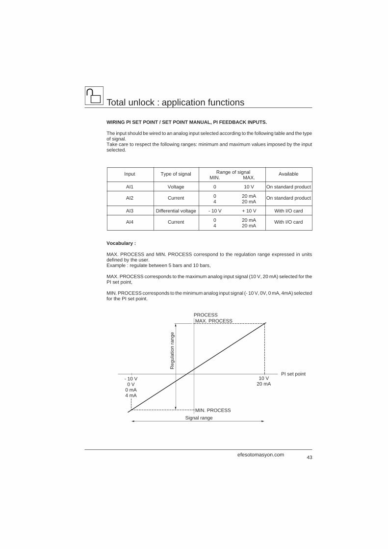
WIRING PI SET POINT / SET POINT MANUAL, PI FEEDBACK INPUTS.
The input should be wired to an analog input selected according to the following table and the typeof signal.Take care to respect the following ranges: minimum and maximum values imposed by the inputselected.
Input Type of signal Range of signal AvailableMIN. MAX.
AI1 Voltage 0 10 V On standard product
AI2 Current 0 20 mA On standard product4 20 mA
AI3 Differential voltage - 10 V + 10 V With I/O card
AI4 Current 0 20 mA With I/O card4 20 mA
Vocabulary :
MAX. PROCESS and MIN. PROCESS correspond to the regulation range expressed in unitsdefined by the user.Example : regulate between 5 bars and 10 bars,
MAX. PROCESS corresponds to the maximum analog input signal (10 V, 20 mA) selected for thePI set point,
MIN. PROCESS corresponds to the minimum analog input signal (- 10 V, 0V, 0 mA, 4mA) selectedfor the PI set point.
PROCESS MAX. PROCESS
MIN. PROCESS
- 10 V0 V
0 mA4 mA
10 V20 mA
Signal range
Reg
ulat
ion
rang
e
PI set point
efesotomasyon.com
44
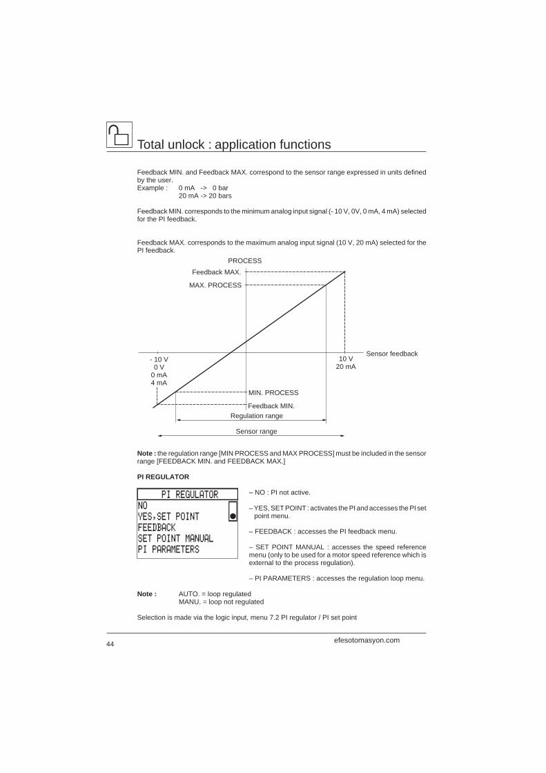
Total unlock : application functions
Feedback MIN. and Feedback MAX. correspond to the sensor range expressed in units definedby the user.Example : 0 mA -> 0 bar
20 mA -> 20 bars
Feedback MIN. corresponds to the minimum analog input signal (- 10 V, 0V, 0 mA, 4 mA) selectedfor the PI feedback.
Feedback MAX. corresponds to the maximum analog input signal (10 V, 20 mA) selected for thePI feedback.
Note : the regulation range [MIN PROCESS and MAX PROCESS] must be included in the sensorrange [FEEDBACK MIN. and FEEDBACK MAX.]
PI REGULATOR
– NO : PI not active.
– YES, SET POINT : activates the PI and accesses the PI setpoint menu.
– FEEDBACK : accesses the PI feedback menu.
– SET POINT MANUAL : accesses the speed referencemenu (only to be used for a motor speed reference which isexternal to the process regulation).
– PI PARAMETERS : accesses the regulation loop menu.
Note : AUTO. = loop regulatedMANU. = loop not regulated
Selection is made via the logic input, menu 7.2 PI regulator / PI set point
- 10 V0 V
0 mA4 mA
10 V20 mA
MAX. PROCESS
PROCESS
Sensor feedback
Regulation range
MIN. PROCESS
Feedback MIN.
Sensor range
Feedback MAX.
PI REGULATOR
NO
YES,SET POINT
FEEDBACK
SET POINT MANUAL
PI PARAMETERS
efesotomasyon.com
45
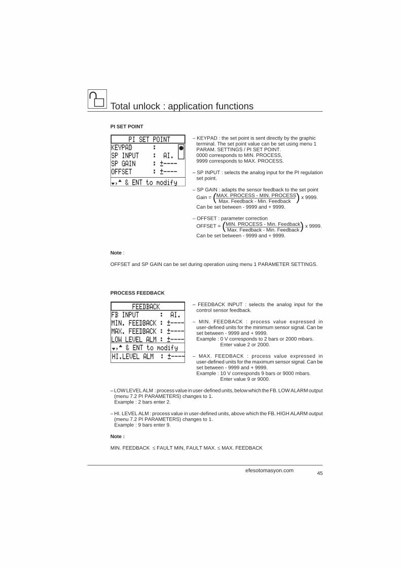
Total unlock : application functions
PI SET POINT
– KEYPAD : the set point is sent directly by the graphicterminal. The set point value can be set using menu 1PARAM. SETTINGS / PI SET POINT.0000 corresponds to MIN. PROCESS,9999 corresponds to MAX. PROCESS.
– SP INPUT : selects the analog input for the PI regulationset point.
– SP GAIN : adapts the sensor feedback to the set pointGain = (MAX. PROCESS - MIN. PROCESS) x 9999.
Max. Feedback - Min. FeedbackCan be set between - 9999 and + 9999.
– OFFSET : parameter correctionOFFSET = (MIN. PROCESS - Min. Feedback) x 9999.
Max. Feedback - Min. FeedbackCan be set between - 9999 and + 9999.
Note :
OFFSET and SP GAIN can be set during operation using menu 1 PARAMETER SETTINGS.
PROCESS FEEDBACK
– FEEDBACK INPUT : selects the analog input for thecontrol sensor feedback.
– MIN. FEEDBACK : process value expressed inuser-defined units for the minimum sensor signal. Can beset between - 9999 and + 9999.Example : 0 V corresponds to 2 bars or 2000 mbars.
Enter value 2 or 2000.
– MAX. FEEDBACK : process value expressed inuser-defined units for the maximum sensor signal. Can beset between - 9999 and + 9999.Example : 10 V corresponds 9 bars or 9000 mbars.
Enter value 9 or 9000.
– LOW LEVEL ALM : process value in user-defined units, below which the FB. LOW ALARM output(menu 7.2 PI PARAMETERS) changes to 1.Example : 2 bars enter 2.
– HI. LEVEL ALM : process value in user-defined units, above which the FB. HIGH ALARM output(menu 7.2 PI PARAMETERS) changes to 1.Example : 9 bars enter 9.
Note :
MIN. FEEDBACK ≤ FAULT MIN, FAULT MAX. ≤ MAX. FEEDBACK
PI SET POINT
KEYPAD :
SP INPUT : AI.
SP GAIN : ±----
OFFSET : ±----
†,™ & ENT to modify
FEEDBACK
FB INPUT : AI.
MIN. FEEDBACK : ±----
MAX. FEEDBACK : ±----
LOW LEVEL ALM : ±----
†,™ & ENT to modify
HI.LEVEL ALM : ±----
efesotomasyon.com
46
Total unlock : application functions
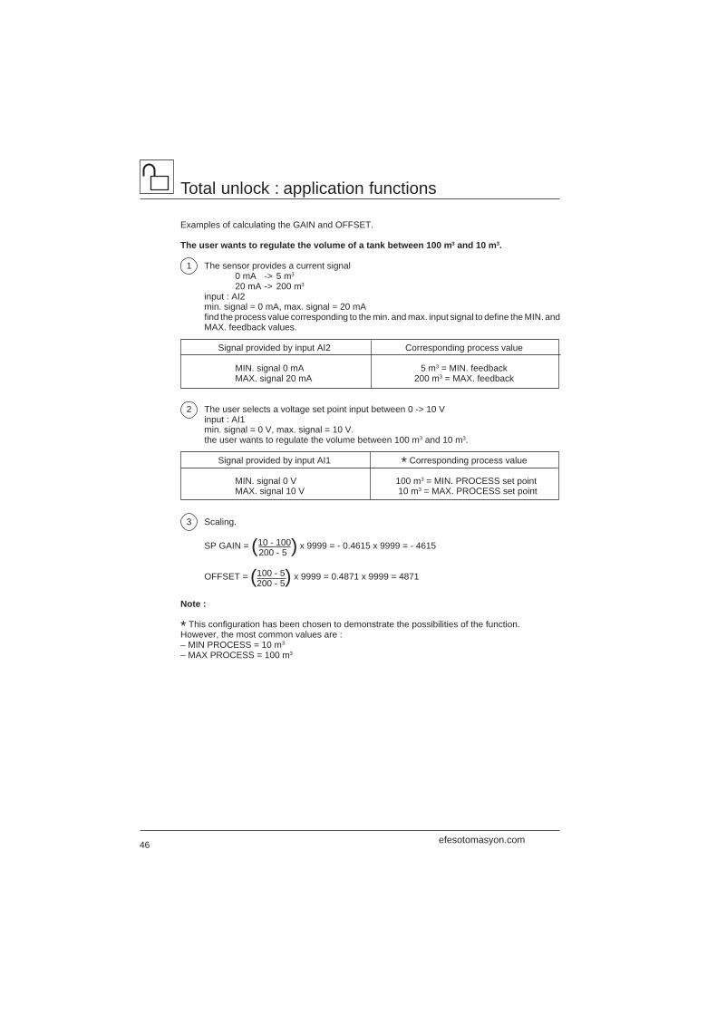
Examples of calculating the GAIN and OFFSET.
The user wants to regulate the volume of a tank between 100 m3 and 10 m3.
1 The sensor provides a current signal0 mA -> 5 m3
20 mA -> 200 m3
input : AI2min. signal = 0 mA, max. signal = 20 mAfind the process value corresponding to the min. and max. input signal to define the MIN. andMAX. feedback values.
Signal provided by input AI2 Corresponding process value
MIN. signal 0 mA 5 m3 = MIN. feedbackMAX. signal 20 mA 200 m3 = MAX. feedback
2 The user selects a voltage set point input between 0 -> 10 Vinput : AI1min. signal = 0 V, max. signal = 10 V.the user wants to regulate the volume between 100 m3 and 10 m3.
Signal provided by input AI1 * Corresponding process value
MIN. signal 0 V 100 m3 = MIN. PROCESS set pointMAX. signal 10 V 10 m3 = MAX. PROCESS set point
3 Scaling.
SP GAIN = (10 - 100) x 9999 = - 0.4615 x 9999 = - 4615 200 - 5
OFFSET = (100 - 5) x 9999 = 0.4871 x 9999 = 4871200 - 5
Note :
* This configuration has been chosen to demonstrate the possibilities of the function.However, the most common values are :– MIN PROCESS = 10 m3
– MAX PROCESS = 100 m3
efesotomasyon.com
47
Total unlock : application functions
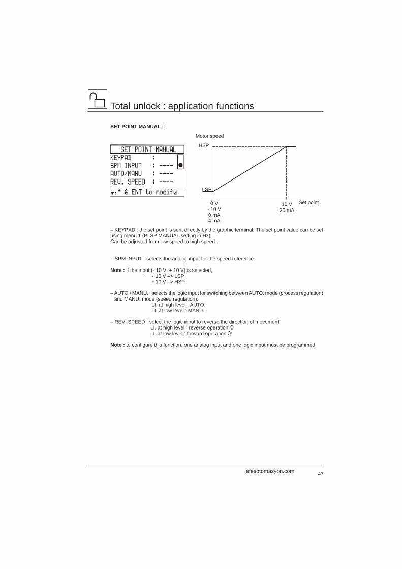
SET POINT MANUAL :
– KEYPAD : the set point is sent directly by the graphic terminal. The set point value can be setusing menu 1 (PI SP MANUAL setting in Hz).Can be adjusted from low speed to high speed.
– SPM INPUT : selects the analog input for the speed reference.
Note : if the input (- 10 V, + 10 V) is selected,- 10 V –> LSP+ 10 V –> HSP
– AUTO./ MANU. : selects the logic input for switching between AUTO. mode (process regulation)and MANU. mode (speed regulation).
LI. at high level : AUTO.LI. at low level : MANU.
– REV. SPEED : select the logic input to reverse the direction of movement.LI. at high level : reverse operation ÂLI. at low level : forward operation Ú
Note : to configure this function, one analog input and one logic input must be programmed.
Motor speed
HSP
LSP
0 V- 10 V0 mA4 mA
10 V20 mA
Set point
SET POINT MANUAL
KEYPAD :
SPM INPUT : ----
AUTO/MANU : ----
REV. SPEED : ----
†,™ & ENT to modify
efesotomasyon.com
48
Total unlock : application functions
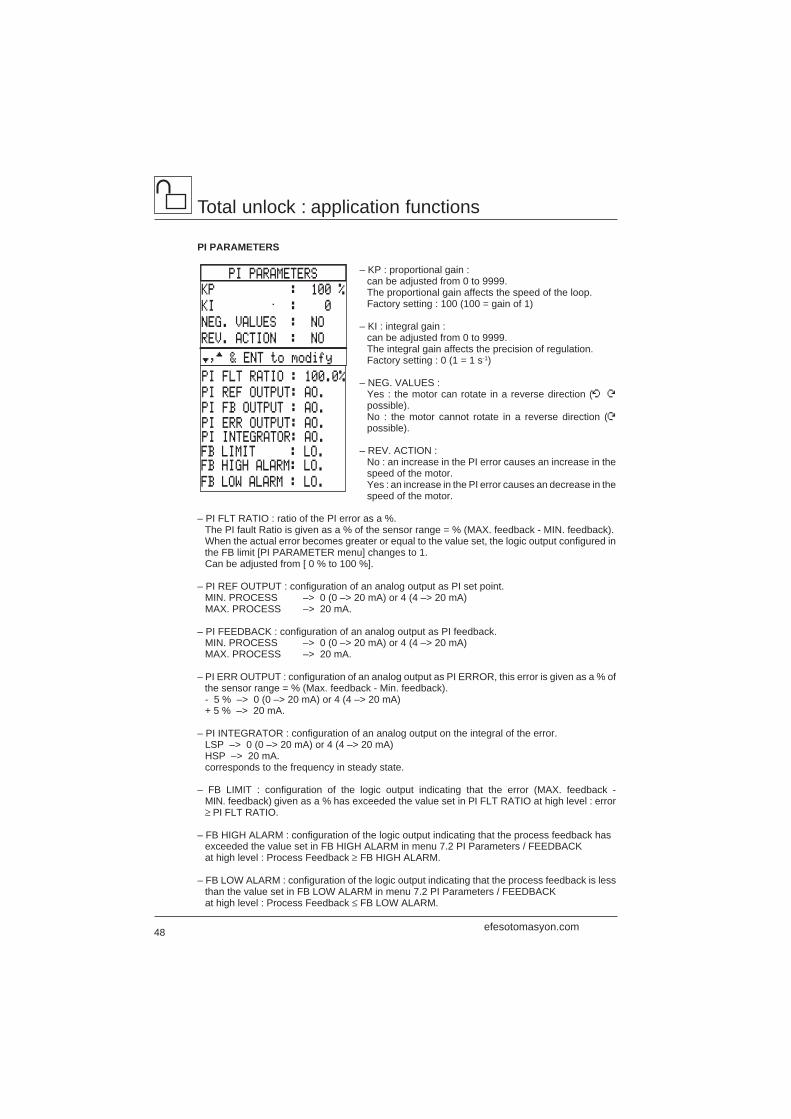
PI PARAMETERS
– KP : proportional gain :can be adjusted from 0 to 9999.The proportional gain affects the speed of the loop.Factory setting : 100 (100 = gain of 1)
– KI : integral gain :can be adjusted from 0 to 9999.The integral gain affects the precision of regulation.Factory setting : 0 (1 = 1 s-1)
– NEG. VALUES :Yes : the motor can rotate in a reverse direction (Â Úpossible).No : the motor cannot rotate in a reverse direction (Úpossible).
– REV. ACTION :No : an increase in the PI error causes an increase in thespeed of the motor.Yes : an increase in the PI error causes an decrease in thespeed of the motor.
– PI FLT RATIO : ratio of the PI error as a %.The PI fault Ratio is given as a % of the sensor range = % (MAX. feedback - MIN. feedback).When the actual error becomes greater or equal to the value set, the logic output configured inthe FB limit [PI PARAMETER menu] changes to 1.Can be adjusted from [ 0 % to 100 %].
– PI REF OUTPUT : configuration of an analog output as PI set point.MIN. PROCESS –> 0 (0 –> 20 mA) or 4 (4 –> 20 mA)MAX. PROCESS –> 20 mA.
– PI FEEDBACK : configuration of an analog output as PI feedback.MIN. PROCESS –> 0 (0 –> 20 mA) or 4 (4 –> 20 mA)MAX. PROCESS –> 20 mA.
– PI ERR OUTPUT : configuration of an analog output as PI ERROR, this error is given as a % ofthe sensor range = % (Max. feedback - Min. feedback).- 5 % –> 0 (0 –> 20 mA) or 4 (4 –> 20 mA)+ 5 % –> 20 mA.
– PI INTEGRATOR : configuration of an analog output on the integral of the error.LSP –> 0 (0 –> 20 mA) or 4 (4 –> 20 mA)HSP –> 20 mA.corresponds to the frequency in steady state.
– FB LIMIT : configuration of the logic output indicating that the error (MAX. feedback -MIN. feedback) given as a % has exceeded the value set in PI FLT RATIO at high level : error≥ PI FLT RATIO.
– FB HIGH ALARM : configuration of the logic output indicating that the process feedback hasexceeded the value set in FB HIGH ALARM in menu 7.2 PI Parameters / FEEDBACKat high level : Process Feedback ≥ FB HIGH ALARM.
– FB LOW ALARM : configuration of the logic output indicating that the process feedback is lessthan the value set in FB LOW ALARM in menu 7.2 PI Parameters / FEEDBACKat high level : Process Feedback ≤ FB LOW ALARM.
PI FLT RATIO : 100.0%
PI REF OUTPUT: AO.PI FB OUTPUT : AO.
PI INTEGRATOR: AO.PI ERR OUTPUT: AO.
FB LIMIT : LO.FB HIGH ALARM: LO.
FB LOW ALARM : LO.
PI PARAMETERS
KP : 100 %
KI : 0
NEG. VALUES : NO
REV. ACTION : NO
†,™ & ENT to modify
efesotomasyon.com
49
Total unlock : application functions
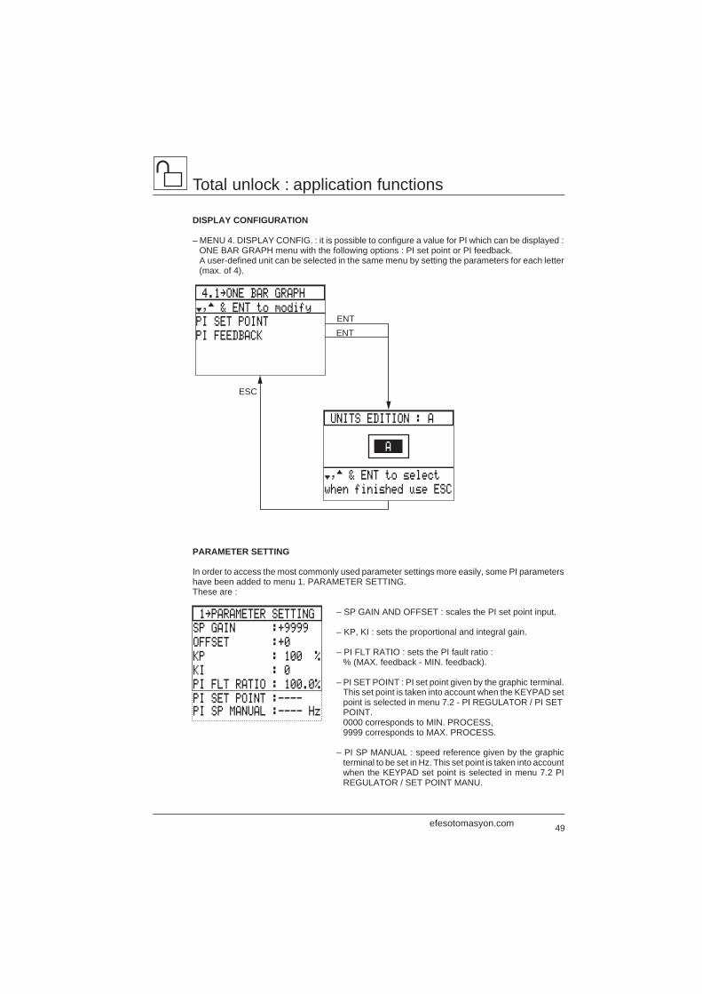
DISPLAY CONFIGURATION
– MENU 4. DISPLAY CONFIG. : it is possible to configure a value for PI which can be displayed :ONE BAR GRAPH menu with the following options : PI set point or PI feedback.A user-defined unit can be selected in the same menu by setting the parameters for each letter(max. of 4).
PARAMETER SETTING
In order to access the most commonly used parameter settings more easily, some PI parametershave been added to menu 1. PARAMETER SETTING.These are :
– SP GAIN AND OFFSET : scales the PI set point input.
– KP, KI : sets the proportional and integral gain.
– PI FLT RATIO : sets the PI fault ratio :% (MAX. feedback - MIN. feedback).
– PI SET POINT : PI set point given by the graphic terminal.This set point is taken into account when the KEYPAD setpoint is selected in menu 7.2 - PI REGULATOR / PI SETPOINT.0000 corresponds to MIN. PROCESS,9999 corresponds to MAX. PROCESS.
– PI SP MANUAL : speed reference given by the graphicterminal to be set in Hz. This set point is taken into accountwhen the KEYPAD set point is selected in menu 7.2 PIREGULATOR / SET POINT MANU.
1‘PARAMETER SETTING
SP GAIN :+9999
OFFSET :+0
KP : 100 %
KI : 0
PI FLT RATIO : 100.0%
PI SET POINT :---- PI SP MANUAL :---- Hz
UNITS EDITION : A
†,™ & ENT to select
when finished use ESC
4.1‘ONE BAR GRAPH
PI SET POINT
PI FEEDBACK
ENTENT
A
†,™ & ENT to modify
ESC
efesotomasyon.com
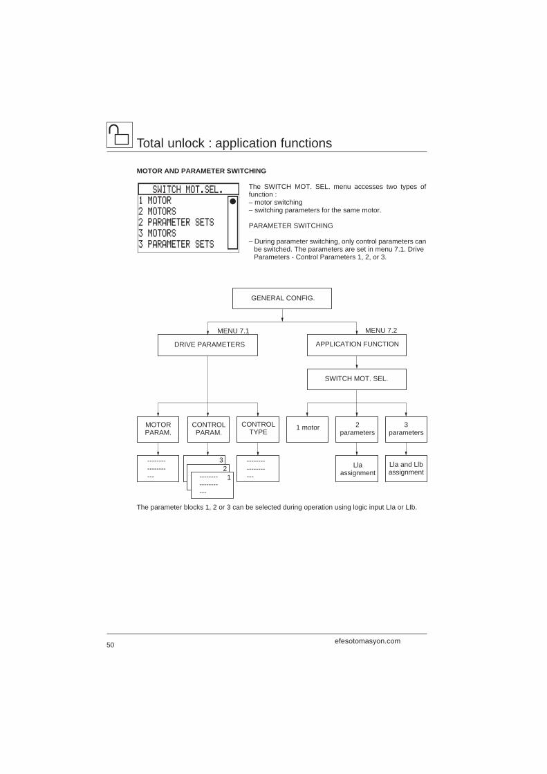
50
Total unlock : application functions
MOTOR AND PARAMETER SWITCHING
The SWITCH MOT. SEL. menu accesses two types offunction :– motor switching– switching parameters for the same motor.
PARAMETER SWITCHING
– During parameter switching, only control parameters canbe switched. The parameters are set in menu 7.1. DriveParameters - Control Parameters 1, 2, or 3.
The parameter blocks 1, 2 or 3 can be selected during operation using logic input LIa or LIb.
-------------------
GENERAL CONFIG.
DRIVE PARAMETERS
SWITCH MOT. SEL.
APPLICATION FUNCTION
1 motor
-------------------
-------------------
MOTORPARAM.
CONTROLTYPE
CONTROLPARAM.
2parameters
3parameters
Lla and Llbassignment
Llaassignment
32
1
MENU 7.1 MENU 7.2
SWITCH MOT.SEL.
1 MOTOR
2 MOTORS
2 PARAMETER SETS
3 MOTORS
3 PARAMETER SETS
efesotomasyon.com
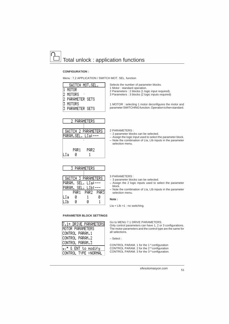
51
SWITCH MOT.SEL.
1 MOTOR
2 MOTORS
2 PARAMETER SETS
3 MOTORS
3 PARAMETER SETS
Total unlock : application functions
CONFIGURATION :
Menu : 7.2 APPLICATION / SWITCH MOT. SEL. function
Selects the number of parameter blocks.1 Motor : standard operation.2 Parameters : 2 blocks (1 logic input required).3 Parameters : 3 blocks (2 logic inputs required)
1 MOTOR : selecting 1 motor deconfigures the motor andparameter SWITCHING function. Operation is then standard.
2 PARAMETERS :– 2 parameter blocks can be selected.– Assign the logic input used to select the parameter block.– Note the combination of LIa, LIb inputs in the parameter
selection menu.
3 PARAMETERS :– 3 parameter blocks can be selected.– Assign the 2 logic inputs used to select the parameter
block.– Note the combination of LIa, LIb inputs in the parameter
selection menu.
Note :
LIa = LIb =1 : no switching.
PARAMETER BLOCK SETTINGS
Go to MENU 7.1 DRIVE PARAMETERS.Only control parameters can have 1, 2 or 3 configurations.The motor parameters and the control type are the same forall selections.
– Select :
CONTROL PARAM. 1 for the 1 st configurationCONTROL PARAM. 2 for the 2 rd configurationCONTROL PARAM. 3 for the 3 rd configuration.
SWITCH 2 PARAMETERS
2 PARAMETERS
PARAM.SEL. LIa:---
PAR1 PAR2
LIa 0 1
SWITCH 3 PARAMETERS
3 PARAMETERS
PARAM. SEL. LIa:---
PARAM. SEL. LIb:---
PAR1 PAR2 PAR3
LIa 0 1 0
LIb 0 0 1
7.1‘ DRIVE PARAMETERS
MOTOR PARAMETERS
CONTROL PARAM.1
CONTROL PARAM.2
CONTROL PARAM.3
†,™ & ENT to modify
CONTROL TYPE :NORMAL
efesotomasyon.com

52
Total unlock : application functions
– Set the parameters using the programming manual, Control Parameters section.
MOTOR SWITCHING
Introduction
The speed controller can only control one motor at a time. The motor must be selected when themotor is stopped.This function imposes the use of a sequence of contactors located between the speed controllerand the motor.
Restrictions on use
I/O :
Logic and analog inputs, logic and analog outputs and relay commands are not multimotor. Theyretain their configuration regardless of the motor selected. However, they are assigned to the motorselected, and can therefore change state during switching.An external sequence may be required in some cases.
Command rules :
The configuration of the high torque rule menu 7.13 is only possible on motor 1.
Thermal fault :
Thermal protection is assigned to the motor identified as MOTOR 1 in the configuration.The calculation is incremented when motor 1 is selected and decremented when motor2 or 3 is selected.
DRIVE PARAMETERS
CONTROL PARAM. 1
CONTROL PARAM. 3
CONTROL PARAM. 2CONTROL TYPEMOTOR PARAM.
MAX. FREQUENCYLOW SPEEDHIGH SPEEDACCELERATIONDECELERATIONACCEL. TYPEDECEL. TYPEALTERNATE RAMPSKIP FREQUENCYREDUCTION OF U
efesotomasyon.com
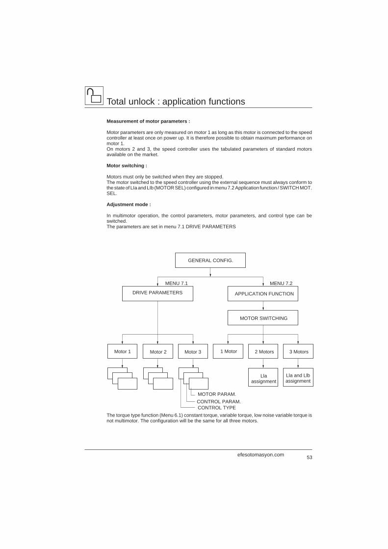
53
Total unlock : application functions
Measurement of motor parameters :
Motor parameters are only measured on motor 1 as long as this motor is connected to the speedcontroller at least once on power up. It is therefore possible to obtain maximum performance onmotor 1.On motors 2 and 3, the speed controller uses the tabulated parameters of standard motorsavailable on the market.
Motor switching :
Motors must only be switched when they are stopped.The motor switched to the speed controller using the external sequence must always conform tothe state of LIa and LIb (MOTOR SEL) configured in menu 7.2 Application function / SWITCH MOT.SEL.
Adjustment mode :
In multimotor operation, the control parameters, motor parameters, and control type can beswitched.The parameters are set in menu 7.1 DRIVE PARAMETERS
The torque type function (Menu 6.1) constant torque, variable torque, low noise variable torque isnot multimotor. The configuration will be the same for all three motors.
MOTOR SWITCHING
APPLICATION FUNCTION
GENERAL CONFIG.
Lla and Llbassignment
Llaassignment
2 Motors 3 Motors1 MotorMotor 2 Motor 3Motor 1
MOTOR PARAM.
MENU 7.2MENU 7.1
DRIVE PARAMETERS
CONTROL PARAM.CONTROL TYPE
efesotomasyon.com
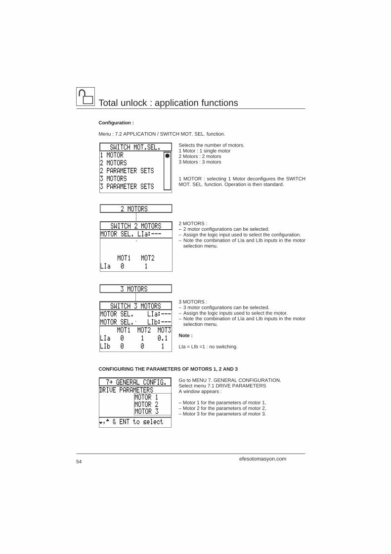
54
Total unlock : application functions
Configuration :
Menu : 7.2 APPLICATION / SWITCH MOT. SEL. function.
Selects the number of motors.1 Motor : 1 single motor2 Motors : 2 motors3 Motors : 3 motors
1 MOTOR : selecting 1 Motor deconfigures the SWITCHMOT. SEL. function. Operation is then standard.
2 MOTORS :– 2 motor configurations can be selected.– Assign the logic input used to select the configuration.– Note the combination of LIa and LIb inputs in the motor
selection menu.
3 MOTORS :– 3 motor configurations can be selected.– Assign the logic inputs used to select the motor.– Note the combination of LIa and LIb inputs in the motor
selection menu.
Note :
LIa = LIb =1 : no switching.
CONFIGURING THE PARAMETERS OF MOTORS 1, 2 AND 3
Go to MENU 7. GENERAL CONFIGURATION.Select menu 7.1 DRIVE PARAMETERSA window appears :
– Motor 1 for the parameters of motor 1,– Motor 2 for the parameters of motor 2,– Motor 3 for the parameters of motor 3.
SWITCH 2 MOTORS
2 MOTORS
MOTOR SEL. LIa:---
MOT1 MOT2
LIa 0 1
SWITCH MOT.SEL.
1 MOTOR
2 MOTORS
2 PARAMETER SETS
3 MOTORS
3 PARAMETER SETS
SWITCH 3 MOTORS
3 MOTORS
MOTOR SEL. LIa:---
MOTOR SEL. LIb:---
MOT1 MOT2 MOT3
LIa 0 1 0.1
LIb 0 0 1
7‘ GENERAL CONFIG.
DRIVE PARAMETERS
†,™ & ENT to select
MOTOR 1MOTOR 2MOTOR 3
efesotomasyon.com
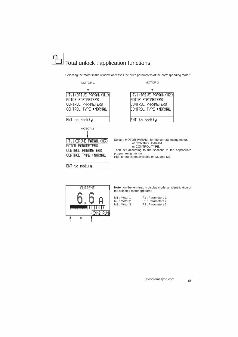
55
Total unlock : application functions
Selecting the motor in the window accesses the drive parameters of the corresponding motor :
Select : MOTOR PARAM., for the corresponding motor.or CONTROL PARAM.,or CONTROL TYPE.
Then set according to the sections in the appropriateprogramming manual.High torque is not available on M2 and M3.
Note : on the terminal, in display mode, an identification ofthe selected motor appears :
M1 : Motor 1 P1 : Parameters 1M2 : Motor 2 P2 : Parameters 2M3 : Motor 3 P3 : Parameters 3
7.1‘DRIVE PARAM.(M2)
MOTOR PARAMETERS
CONTROL PARAMETERS
CONTROL TYPE :NORMAL
ENT to modify
MOTOR 2
7.1‘DRIVE PARAM.(M3)
MOTOR PARAMETERS
CONTROL PARAMETERS
CONTROL TYPE :NORMAL
ENT to modify
MOTOR 3
7.1‘DRIVE PARAM.(M1)
MOTOR PARAMETERS
CONTROL PARAMETERS
CONTROL TYPE :NORMAL
ENT to modify
MOTOR 1
CURRENT
6.6 A
ÚM2 RUN
efesotomasyon.com
56
Total unlock : application functions
Recommended sequence :
R2 configured with the speed controller running. It is necessary to cut the run signal tochange the motor, because relay R2 in this configuration does not change state for azero reference if the run signal has not been disabled.Thermal protection only on motor 1.
Check that the power required for the contactor coils corresponds with thatprovided by contacts R1 and R2.
T1
F3
F2 F4
A1
CL1
CL2
LI3
LI2
LI1
Q1
KM1
KM3 KM4
F2
KM3
M2 3 c
KM2
M1 3 c
F3
KM4
M3 3 c
KA1 KA1
LIb
LIa
Fault
KM2
KM4
KM3
KM2
KM3
KM4
KM2
KM3
KM4
KM3
KM2
KM4
A1
R2C
R2A
KM1
KA1
M1 M3M2
A1
R1C
R1A
AT
F3
F2
KA1
MA
KA1
KA1
Q1
(1s)
efesotomasyon.com
57
Total unlock : application functions
Example of brake sequence :
R3 brake command
Brakesmotor 1 motor 2 motor 3
KM22
KM2
KM32
KM3
KM42
A1
R3C
R3A
KM4
KM1
efesotomasyon.com
58
ENT
ENT
ENT
ESC
LOGIC OUT. FUNCTIONS
READY STATE
RUNNING STATE “
AT SPEED “
FWD DIRECTION
†,™ & ENT to select
SET
LEVEL
%
0 ‘ 200
THERMAL LEVEL ‘LO?
LO1 AT SPEED
LO2 CURRENT LIMIT
R2 RUNNING STATE
CLEAR ASSIGNMENT
Select output & ENT
REASSIGN ?
LO1 AT SPEED
’
LO1 THERMAL LEVEL
ENT to confirm
ESC to abort
ESC
ESC
ENT
TERM./KEYPAD
FAULT STATE “
DRIVE THER.AL.
LOSS 4-20 mAFREQ. LEVEL
CURRENT LEVEL
THERMAL LEV.
JOG ENABLED
FB HIGH ALARMFB LOW ALARM
REV. DIRECTION
AUTO/MANUALCURRENT LIMIT “
ENT ESC
7.3‘OUTPUT ASSIGN.
LOGIC OUTPUTS
ANALOG OUTPUTS
†,™ & ENT to select
Total unlock : output assignment
Output assignment
LOGIC OUTPUTS
Comments :
– If the selected output is assigned to a function,a warning message appears on the screen.
– It is possible to assign the same function toseveral logic outputs.
Select the Output assignment menu in the Generalconfiguration mode.
This menu is used to :
– display the assignment of the logic and analog outputs,
– reassign outputs which have not previously beenreassigned.
Lists the functions which can be assigned to logic outputs.
Each assigned function is marked by an arrow : these are eitherfactory settings or reassignments carried out previously.
Comments :
– The FAULT STATE function is assigned to relay R1 whichcannot be reassigned.
– The DRIVE THER. AL. function only applies to Altivar modelsfrom the ATV-66D16N4 upwards.
The TERM./KEYPAD, AUTO/MANUAL, LOSS FOLLOWER,JOG ENABLED, FB HIGH ALARM, FB LOW ALARM functionsappear on this screen only when validated previously.
Example of reassigning a logic output
efesotomasyon.com
59
ENT SELECT
0-20mA
4-20mA
ANALOG OUT.FUNCTIONS
MOT. CURRENT “
MOTOR SPEED “
MOTOR POWER
MOTOR TORQUE
†,™ & ENT to select
If necessary, change the outputsignal : preset at 0-20 mA.
Modify the output signal andconfirm by pressing ENT.
Total unlock : output assignment
ANALOG OUTPUTS
Special case : modification of the signal of an assigned output
Lists the functions which can be assigned to analogoutputs.
Each function assigned as a factory setting is markedby an arrow.
Example of reassigning an analog output
Characteristics :
– MOT. CURRENT : 20 mA = 200 % of the motor nominal current.– MOTOR SPEED : 20 mA = 100 % of high speed HS, 0 mA or 4 mA = zero speed.– MOTOR POWER : 20 mA = 200 % of the power of the motor to be used with the speed controllerin constant torque configuration.– MOTOR TORQUE : 20 mA = 200 % of nominal torque.– THERM. STATE : 20 mA = 200 % of the nominal thermal state of the motor,– RAMP OUTPUT : 20 mA = 100 % of high speed, 0 mA or 4 mA = low speed.
ENT ESC
REASSIGN ?
AO1 MOTOR SPEED
’
AO1 THERM. STATE
ENT to confirm
ESC to abort
THERM. STATE ‘AO?
AO1 MOTOR SPEED
AO2 I MOTOR
Select output & ENT
ANALOG OUT.FUNCTIONS
MOT. CURRENT “
MOTOR SPEED “
MOTOR POWER
MOTOR TORQUE
†,™ & ENT to select
THERM. STATE
ENT
ESC
ENT ENT SELECT
0-20mA
4-20mA
RAMP OUTPUT
PI SET POINT
PI FEEDBACK
PI ERROR
PI INTEGRATOR
efesotomasyon.com
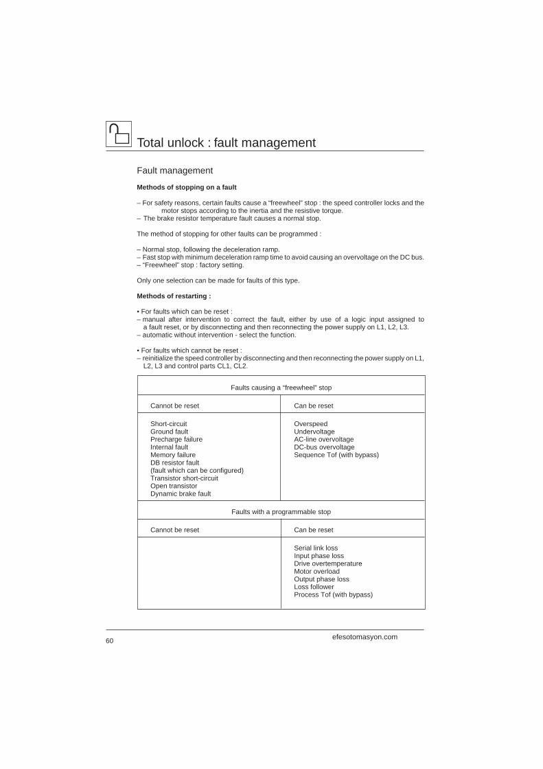
60
Total unlock : fault management
Fault management
Methods of stopping on a fault
– For safety reasons, certain faults cause a “freewheel” stop : the speed controller locks and the motor stops according to the inertia and the resistive torque.
– The brake resistor temperature fault causes a normal stop.
The method of stopping for other faults can be programmed :
– Normal stop, following the deceleration ramp.– Fast stop with minimum deceleration ramp time to avoid causing an overvoltage on the DC bus.– “Freewheel” stop : factory setting.
Only one selection can be made for faults of this type.
Methods of restarting :
• For faults which can be reset :– manual after intervention to correct the fault, either by use of a logic input assigned to
a fault reset, or by disconnecting and then reconnecting the power supply on L1, L2, L3.– automatic without intervention - select the function.
• For faults which cannot be reset :– reinitialize the speed controller by disconnecting and then reconnecting the power supply on L1,
L2, L3 and control parts CL1, CL2.
Faults causing a “freewheel” stop
Cannot be reset Can be reset
Short-circuit OverspeedGround fault UndervoltagePrecharge failure AC-line overvoltageInternal fault DC-bus overvoltageMemory failure Sequence Tof (with bypass)DB resistor fault(fault which can be configured)Transistor short-circuitOpen transistorDynamic brake fault
Faults with a programmable stop
Cannot be reset Can be reset
Serial link lossInput phase lossDrive overtemperatureMotor overloadOutput phase lossLoss followerProcess Tof (with bypass)
efesotomasyon.com
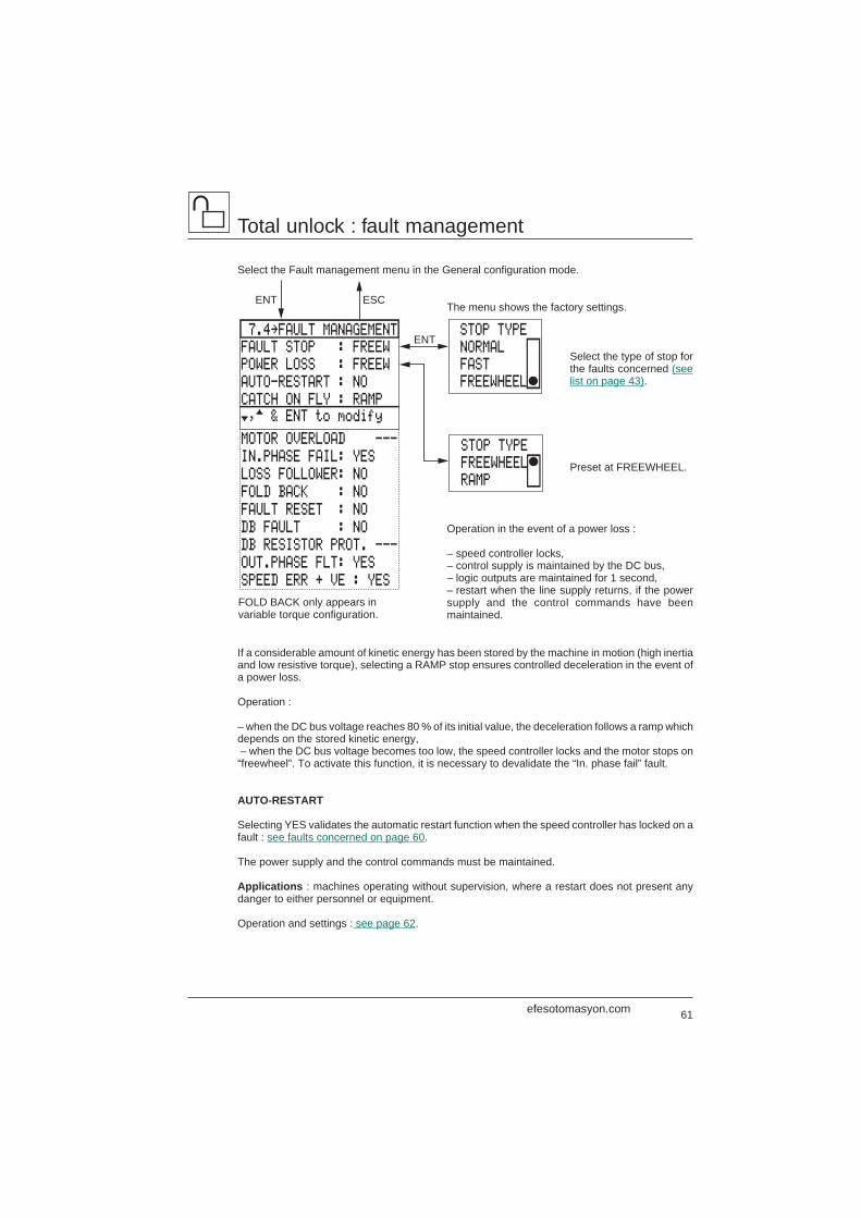
61
Total unlock : fault management
Select the Fault management menu in the General configuration mode.
The menu shows the factory settings.
Select the type of stop forthe faults concerned (seelist on page 43).
Preset at FREEWHEEL.
Operation in the event of a power loss :
– speed controller locks,– control supply is maintained by the DC bus,– logic outputs are maintained for 1 second,– restart when the line supply returns, if the powersupply and the control commands have beenmaintained.
If a considerable amount of kinetic energy has been stored by the machine in motion (high inertiaand low resistive torque), selecting a RAMP stop ensures controlled deceleration in the event ofa power loss.
Operation :
– when the DC bus voltage reaches 80 % of its initial value, the deceleration follows a ramp whichdepends on the stored kinetic energy, – when the DC bus voltage becomes too low, the speed controller locks and the motor stops on“freewheel”. To activate this function, it is necessary to devalidate the “In. phase fail” fault.
AUTO-RESTART
Selecting YES validates the automatic restart function when the speed controller has locked on afault : see faults concerned on page 60.
The power supply and the control commands must be maintained.
Applications : machines operating without supervision, where a restart does not present anydanger to either personnel or equipment.
Operation and settings : see page 62.
FOLD BACK only appears invariable torque configuration.
ENT ESC
STOP TYPE
NORMAL
FAST
FREEWHEEL
7.4‘FAULT MANAGEMENT
FAULT STOP : FREEW
POWER LOSS : FREEW
AUTO-RESTART : NO
†,™ & ENT to modifyCATCH ON FLY : RAMP
MOTOR OVERLOAD ---
IN.PHASE FAIL: YES
LOSS FOLLOWER: NO
FOLD BACK : NO
FAULT RESET : NO
DB FAULT : NO
DB RESISTOR PROT. ---
OUT.PHASE FLT: YES
SPEED ERR + VE : YES
ENT
STOP TYPE
FREEWHEEL
RAMP
efesotomasyon.com
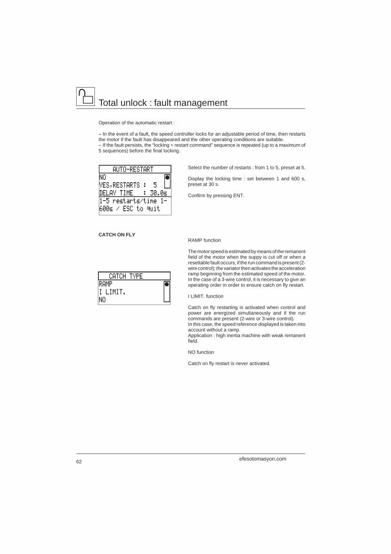
62
Total unlock : fault management
Operation of the automatic restart :
– In the event of a fault, the speed controller locks for an adjustable period of time, then restartsthe motor if the fault has disappeared and the other operating conditions are suitable.– If the fault persists, the “locking + restart command” sequence is repeated (up to a maximum of5 sequences) before the final locking.
Select the number of restarts : from 1 to 5, preset at 5.
Display the locking time : set between 1 and 600 s,preset at 30 s.
Confirm by pressing ENT.
CATCH ON FLYRAMP function
The motor speed is estimated by means of the remanentfield of the motor when the suppy is cut off or when aresettable fault occurs, if the run command is present (2-wire control); the variator then activates the accelerationramp beginning from the estimated speed of the motor.In the case of a 3-wire control, it is necessary to give anoperating order in order to ensure catch on fly restart.
I LIMIT. function
Catch on fly restarting is activated when control andpower are energized simultaneously and if the runcommands are present (2-wire or 3-wire control).In this case, the speed reference displayed is taken intoaccount without a ramp.Application : high inertia machine with weak remanentfield.
NO function
Catch on fly restart is never activated.
AUTO-RESTART
NO
YES,RESTARTS : 5
DELAY TIME : 30.0s
1-5 restarts/time 1-
600s / ESC to quit
CATCH TYPE
RAMP
I LIMIT.
NO
efesotomasyon.com
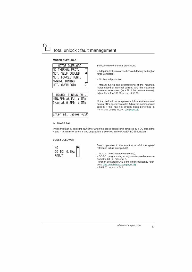
63
Total unlock : fault management
MOTOR OVERLOAD
Select the motor thermal protection :
– Adaption to the motor : self-cooled (factory setting) orforce-ventilated.
– No thermal protection.
– Manual tuning and programming of the minimummotor speed at nominal current, and the maximumcurrent at zero speed (as a % of the nominal values),adjust from 0 to 100 %, preset at 50 %.
Motor overload : factory preset at 0.9 times the nominalcurrent of the speed controller. Adjust the motor nominalcurrent if this has not already been performed inParameter setting mode : see page 15.
IN. PHASE FAIL
Inhibit this fault by selecting NO either when the speed controller is powered by a DC bus at the+ and – terminals or when a stop on gradient is selected in the POWER LOSS function.
LOSS FOLLOWER
Select operation in the event of a 4-20 mA speedreference failure on input AI2 :
– NO : no detection (factory setting).– GO TO : programming an adjustable speed referencefrom 0 to 60 Hz, preset at 0.Function activated if AI2 is the single frequency refer-ence (AI1 devalidated, see page 36),– FAULT : lock on a fault.
MANUAL TUNING OVL.
MIN.SPD at F.L.: 50%
Imax at 0 SPD : 50%
Enter all values ‘ESC
MOTOR OVERLOAD
NO THERMAL PROT.
MOT. SELF COOLED
MOT. FORCED VENT.
MANUAL TUNING
MOT. OVERLOAD: A
NO
GO TO: 0.0Hz
FAULT
efesotomasyon.com
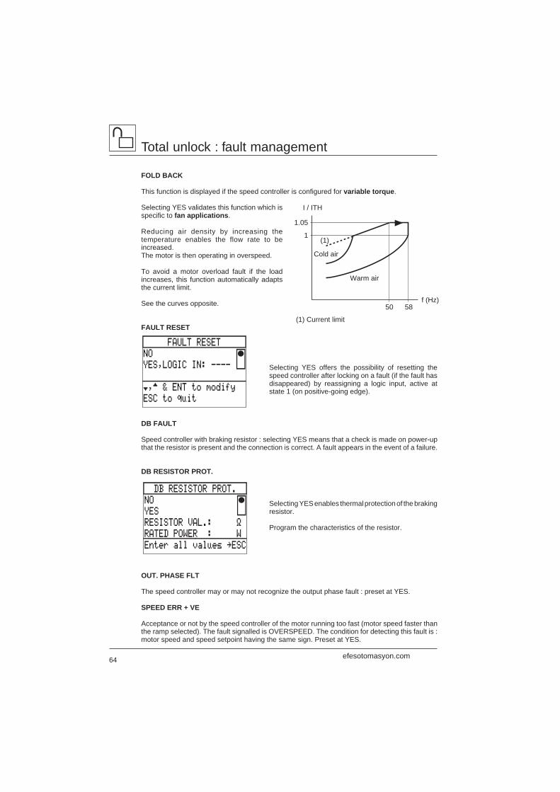
64
Total unlock : fault management
FOLD BACK
This function is displayed if the speed controller is configured for variable torque.
Selecting YES validates this function which isspecific to fan applications.
Reducing air density by increasing thetemperature enables the flow rate to beincreased.The motor is then operating in overspeed.
To avoid a motor overload fault if the loadincreases, this function automatically adaptsthe current limit.
See the curves opposite.
(1) Current limitFAULT RESET
Selecting YES offers the possibility of resetting thespeed controller after locking on a fault (if the fault hasdisappeared) by reassigning a logic input, active atstate 1 (on positive-going edge).
DB FAULT
Speed controller with braking resistor : selecting YES means that a check is made on power-upthat the resistor is present and the connection is correct. A fault appears in the event of a failure.
DB RESISTOR PROT.
Selecting YES enables thermal protection of the brakingresistor.
Program the characteristics of the resistor.
OUT. PHASE FLT
The speed controller may or may not recognize the output phase fault : preset at YES.
SPEED ERR + VE
Acceptance or not by the speed controller of the motor running too fast (motor speed faster thanthe ramp selected). The fault signalled is OVERSPEED. The condition for detecting this fault is :motor speed and speed setpoint having the same sign. Preset at YES.
Cold air
Warm air
1.05
1
I / ITH
50 58f (Hz)
(1)
FAULT RESET
NO
YES,LOGIC IN: ----
†,™ & ENT to modify
ESC to quit
DB RESISTOR PROT.
NO
YES
RESISTOR VAL.: Ω
RATED POWER : W
Enter all values ‘ESC
efesotomasyon.com
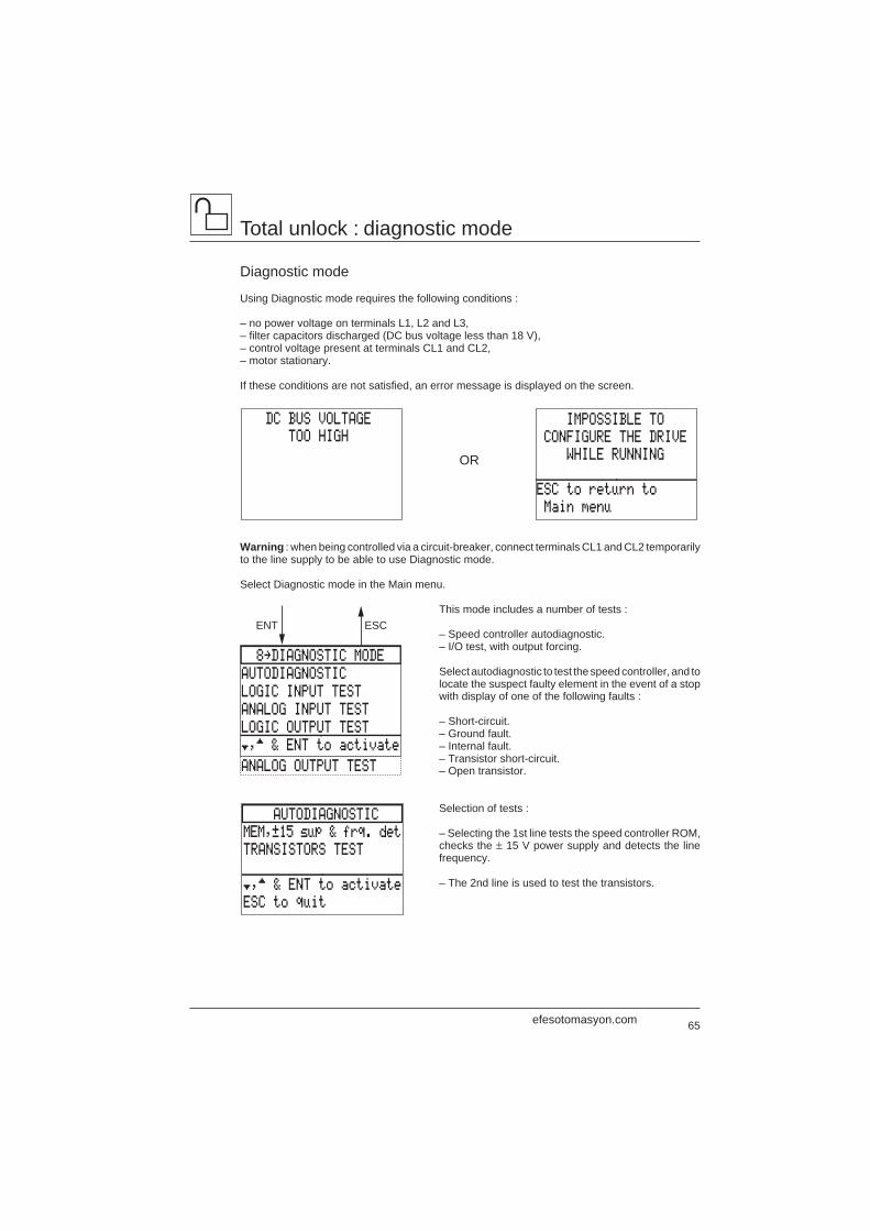
65
ENT ESC
8‘DIAGNOSTIC MODE
AUTODIAGNOSTIC
LOGIC INPUT TEST
ANALOG INPUT TEST
LOGIC OUTPUT TEST
†,™ & ENT to activate
ANALOG OUTPUT TEST
DC BUS VOLTAGE
TOO HIGH
OR
IMPOSSIBLE TO
CONFIGURE THE DRIVE
WHILE RUNNING
ESC to return to
Main menu
AUTODIAGNOSTIC
MEM,±15 sup & frq. det
TRANSISTORS TEST
†,™ & ENT to activate
ESC to quit
Total unlock : diagnostic mode
Diagnostic mode
Using Diagnostic mode requires the following conditions :
– no power voltage on terminals L1, L2 and L3,– filter capacitors discharged (DC bus voltage less than 18 V),– control voltage present at terminals CL1 and CL2,– motor stationary.
If these conditions are not satisfied, an error message is displayed on the screen.
Warning : when being controlled via a circuit-breaker, connect terminals CL1 and CL2 temporarilyto the line supply to be able to use Diagnostic mode.
Select Diagnostic mode in the Main menu.
This mode includes a number of tests :
– Speed controller autodiagnostic.– I/O test, with output forcing.
Select autodiagnostic to test the speed controller, and tolocate the suspect faulty element in the event of a stopwith display of one of the following faults :
– Short-circuit.– Ground fault.– Internal fault.– Transistor short-circuit.– Open transistor.
Selection of tests :
– Selecting the 1st line tests the speed controller ROM,checks the ± 15 V power supply and detects the linefrequency.
– The 2nd line is used to test the transistors.
efesotomasyon.com
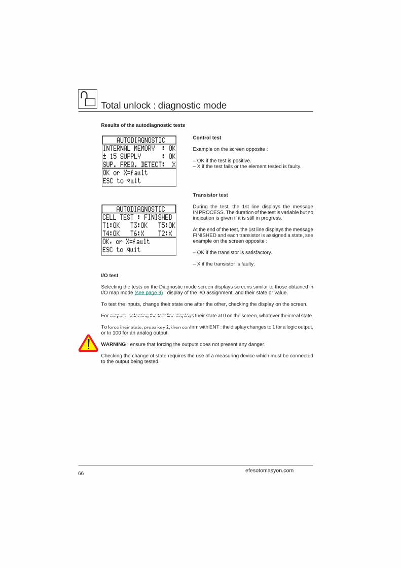
66
Total unlock : diagnostic mode
Results of the autodiagnostic tests
Control test
Example on the screen opposite :
– OK if the test is positive.– X if the test fails or the element tested is faulty.
Transistor test
During the test, the 1st line displays the messageIN PROCESS. The duration of the test is variable but noindication is given if it is still in progress.
At the end of the test, the 1st line displays the messageFINISHED and each transistor is assigned a state, seeexample on the screen opposite :
– OK if the transistor is satisfactory.
– X if the transistor is faulty.
I/O test
Selecting the tests on the Diagnostic mode screen displays screens similar to those obtained inI/O map mode (see page 9) : display of the I/O assignment, and their state or value.
To test the inputs, change their state one after the other, checking the display on the screen.
For outputs, selecting the test line displays their state at 0 on the screen, whatever their real state.
To force their state, press key 1, then confirm with ENT : the display changes to 1 for a logic output,or to 100 for an analog output.
WARNING : ensure that forcing the outputs does not present any danger.
Checking the change of state requires the use of a measuring device which must be connectedto the output being tested.
AUTODIAGNOSTIC
INTERNAL MEMORY : OK
± 15 SUPPLY : OK
SUP. FREQ. DETECT: X
OK or X=fault
ESC to quit
AUTODIAGNOSTIC
CELL TEST : FINISHED
T1:OK T3:OK T5:OK
T4:OK T6:X T2:X
OK, or X=fault
ESC to quit
efesotomasyon.com
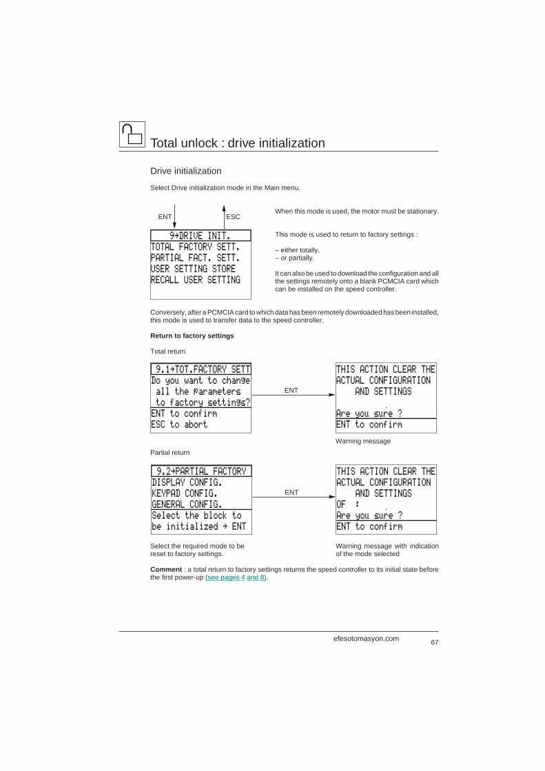
67
9.2‘PARTIAL FACTORY
DISPLAY CONFIG.
KEYPAD CONFIG.
GENERAL CONFIG.
Select the block to
be initialized ‘ ENT
THIS ACTION CLEAR THE
ACTUAL CONFIGURATION
AND SETTINGS
OF :
Are you sure ?
ENT to confirm
ENT
9‘DRIVE INIT.
TOTAL FACTORY SETT.
PARTIAL FACT. SETT.
USER SETTING STORE
RECALL USER SETTING
ENT ESC
9.1‘TOT.FACTORY SETT
Do you want to change
all the parameters
to factory settings?
ENT to confirm
ESC to abort
THIS ACTION CLEAR THE
ACTUAL CONFIGURATION
AND SETTINGS
Are you sure ?
ENT to confirm
ENT
Total unlock : drive initialization
Drive initialization
Select Drive initialization mode in the Main menu.
When this mode is used, the motor must be stationary.
This mode is used to return to factory settings :
– either totally,– or partially.
It can also be used to download the configuration and allthe settings remotely onto a blank PCMCIA card whichcan be installed on the speed controller.
Conversely, after a PCMCIA card to which data has been remotely downloaded has been installed,this mode is used to transfer data to the speed controller.
Return to factory settings
Total return
Partial return
Select the required mode to bereset to factory settings.
Comment : a total return to factory settings returns the speed controller to its initial state beforethe first power-up (see pages 4 and 8).
Warning message
Warning message with indicationof the mode selected
efesotomasyon.com
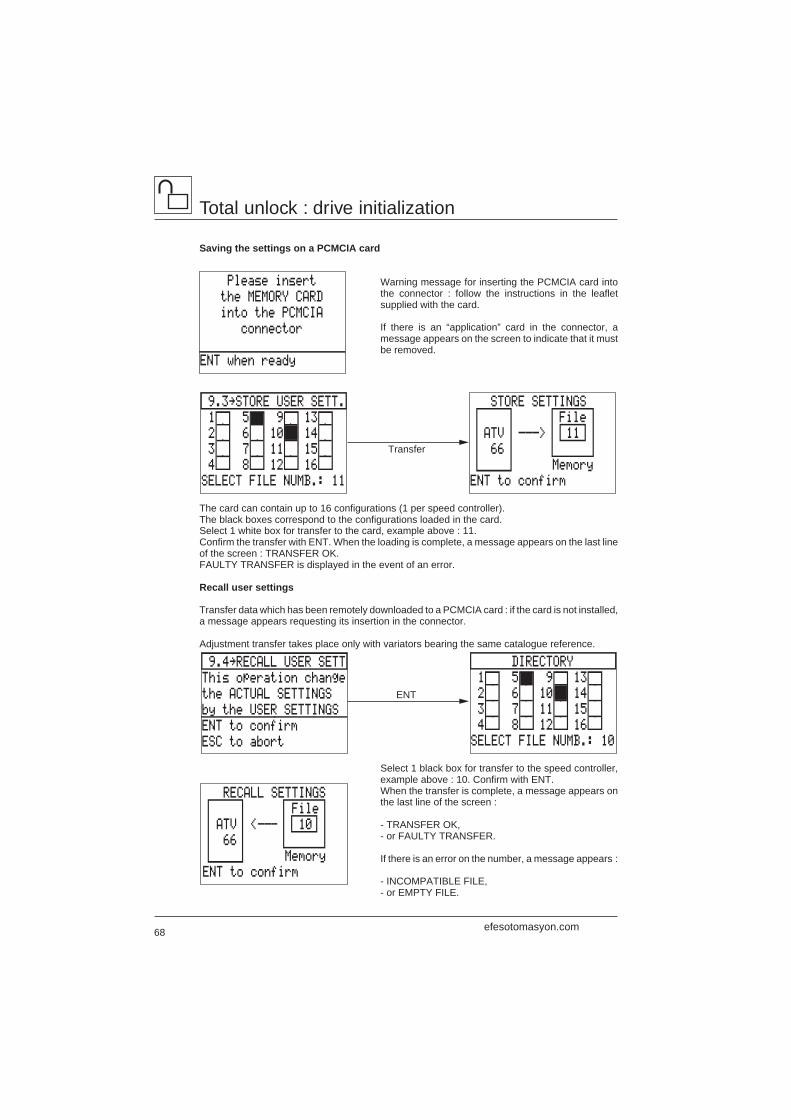
68
RECALL SETTINGS
File
ATV <––- 10
66
Memory
ENT to confirm
DIRECTORY
1 5 9 13
2 6 10 14
3 7 11 15
4 8 12 16
SELECT FILE NUMB.: 10
9.4‘RECALL USER SETT
This operation change
the ACTUAL SETTINGS
by the USER SETTINGS
ENT to confirm
ESC to abort
ENT
9.3‘STORE USER SETT.
1 5 9 13
2 6 10 14
3 7 11 15
4 8 12 16
SELECT FILE NUMB.: 11
STORE SETTINGS
File
ATV –––> 11
66
Memory
ENT to confirm
Transfer
Please insert
the MEMORY CARD
into the PCMCIA
connector
ENT when ready
Total unlock : drive initialization
Saving the settings on a PCMCIA card
Warning message for inserting the PCMCIA card intothe connector : follow the instructions in the leafletsupplied with the card.
If there is an “application” card in the connector, amessage appears on the screen to indicate that it mustbe removed.
The card can contain up to 16 configurations (1 per speed controller).The black boxes correspond to the configurations loaded in the card.Select 1 white box for transfer to the card, example above : 11.Confirm the transfer with ENT. When the loading is complete, a message appears on the last lineof the screen : TRANSFER OK.FAULTY TRANSFER is displayed in the event of an error.
Recall user settings
Transfer data which has been remotely downloaded to a PCMCIA card : if the card is not installed,a message appears requesting its insertion in the connector.
Adjustment transfer takes place only with variators bearing the same catalogue reference.
Select 1 black box for transfer to the speed controller,example above : 10. Confirm with ENT.When the transfer is complete, a message appears onthe last line of the screen :
- TRANSFER OK,- or FAULTY TRANSFER.
If there is an error on the number, a message appears :
- INCOMPATIBLE FILE,- or EMPTY FILE.
efesotomasyon.com
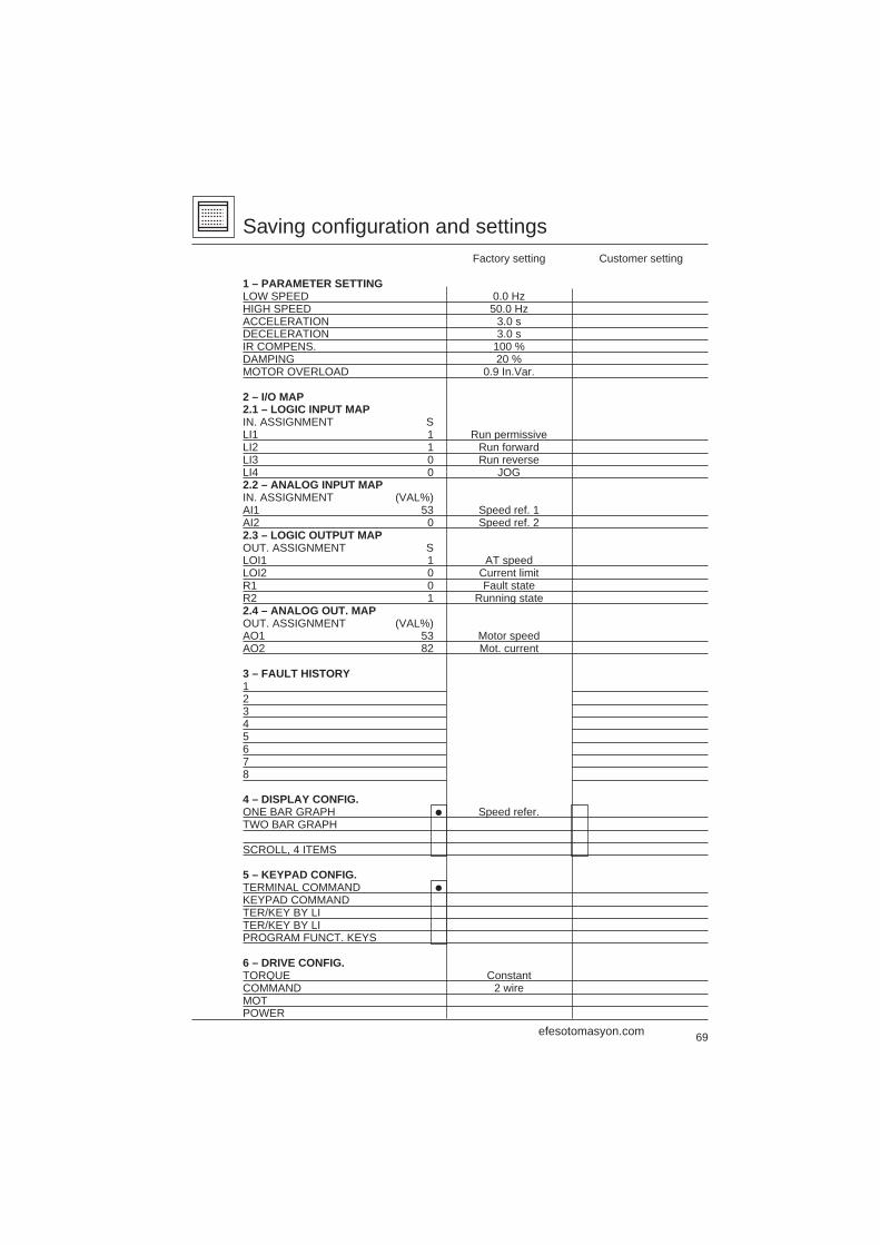
69
Saving configuration and settingsFactory setting Customer setting
1 – PARAMETER SETTINGLOW SPEED 0.0 HzHIGH SPEED 50.0 HzACCELERATION 3.0 sDECELERATION 3.0 sIR COMPENS. 100 %DAMPING 20 %MOTOR OVERLOAD 0.9 In.Var.
2 – I/O MAP2.1 – LOGIC INPUT MAPIN. ASSIGNMENT SLI1 1 Run permissiveLI2 1 Run forwardLI3 0 Run reverseLI4 0 JOG2.2 – ANALOG INPUT MAPIN. ASSIGNMENT (VAL%)AI1 53 Speed ref. 1AI2 0 Speed ref. 22.3 – LOGIC OUTPUT MAPOUT. ASSIGNMENT SLOI1 1 AT speedLOI2 0 Current limitR1 0 Fault stateR2 1 Running state2.4 – ANALOG OUT. MAPOUT. ASSIGNMENT (VAL%)AO1 53 Motor speedAO2 82 Mot. current
3 – FAULT HISTORY12345678
4 – DISPLAY CONFIG.ONE BAR GRAPH i Speed refer.TWO BAR GRAPH
SCROLL, 4 ITEMS
5 – KEYPAD CONFIG.TERMINAL COMMAND i
KEYPAD COMMANDTER/KEY BY LITER/KEY BY LIPROGRAM FUNCT. KEYS
6 – DRIVE CONFIG.TORQUE ConstantCOMMAND 2 wireMOTPOWER
efesotomasyon.com
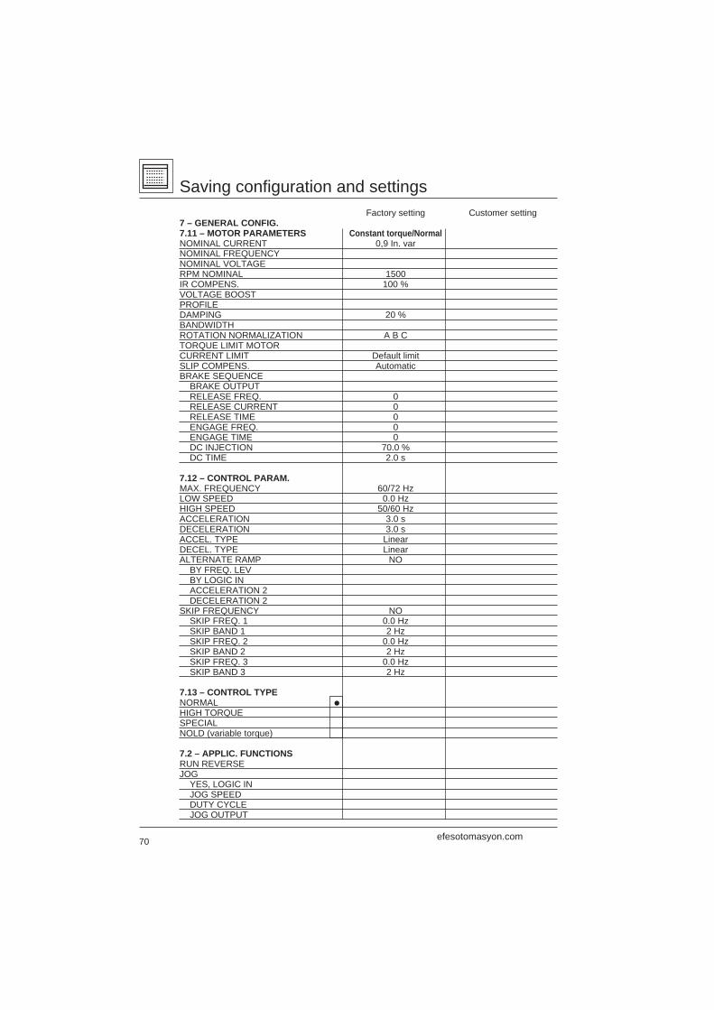
70
Saving configuration and settingsFactory setting Customer setting
7 – GENERAL CONFIG.7.11 – MOTOR PARAMETERS Constant torque/NormalNOMINAL CURRENT 0,9 In. varNOMINAL FREQUENCYNOMINAL VOLTAGERPM NOMINAL 1500IR COMPENS. 100 %VOLTAGE BOOSTPROFILEDAMPING 20 %BANDWIDTHROTATION NORMALIZATION A B CTORQUE LIMIT MOTORCURRENT LIMIT Default limitSLIP COMPENS. AutomaticBRAKE SEQUENCE
BRAKE OUTPUTRELEASE FREQ. 0RELEASE CURRENT 0RELEASE TIME 0ENGAGE FREQ. 0ENGAGE TIME 0DC INJECTION 70.0 %DC TIME 2.0 s
7.12 – CONTROL PARAM.MAX. FREQUENCY 60/72 HzLOW SPEED 0.0 HzHIGH SPEED 50/60 HzACCELERATION 3.0 sDECELERATION 3.0 sACCEL. TYPE LinearDECEL. TYPE LinearALTERNATE RAMP NO
BY FREQ. LEVBY LOGIC INACCELERATION 2DECELERATION 2
SKIP FREQUENCY NOSKIP FREQ. 1 0.0 HzSKIP BAND 1 2 HzSKIP FREQ. 2 0.0 HzSKIP BAND 2 2 HzSKIP FREQ. 3 0.0 HzSKIP BAND 3 2 Hz
7.13 – CONTROL TYPENORMAL i
HIGH TORQUESPECIALNOLD (variable torque)
7.2 – APPLIC. FUNCTIONSRUN REVERSEJOG
YES, LOGIC INJOG SPEEDDUTY CYCLEJOG OUTPUT
efesotomasyon.com
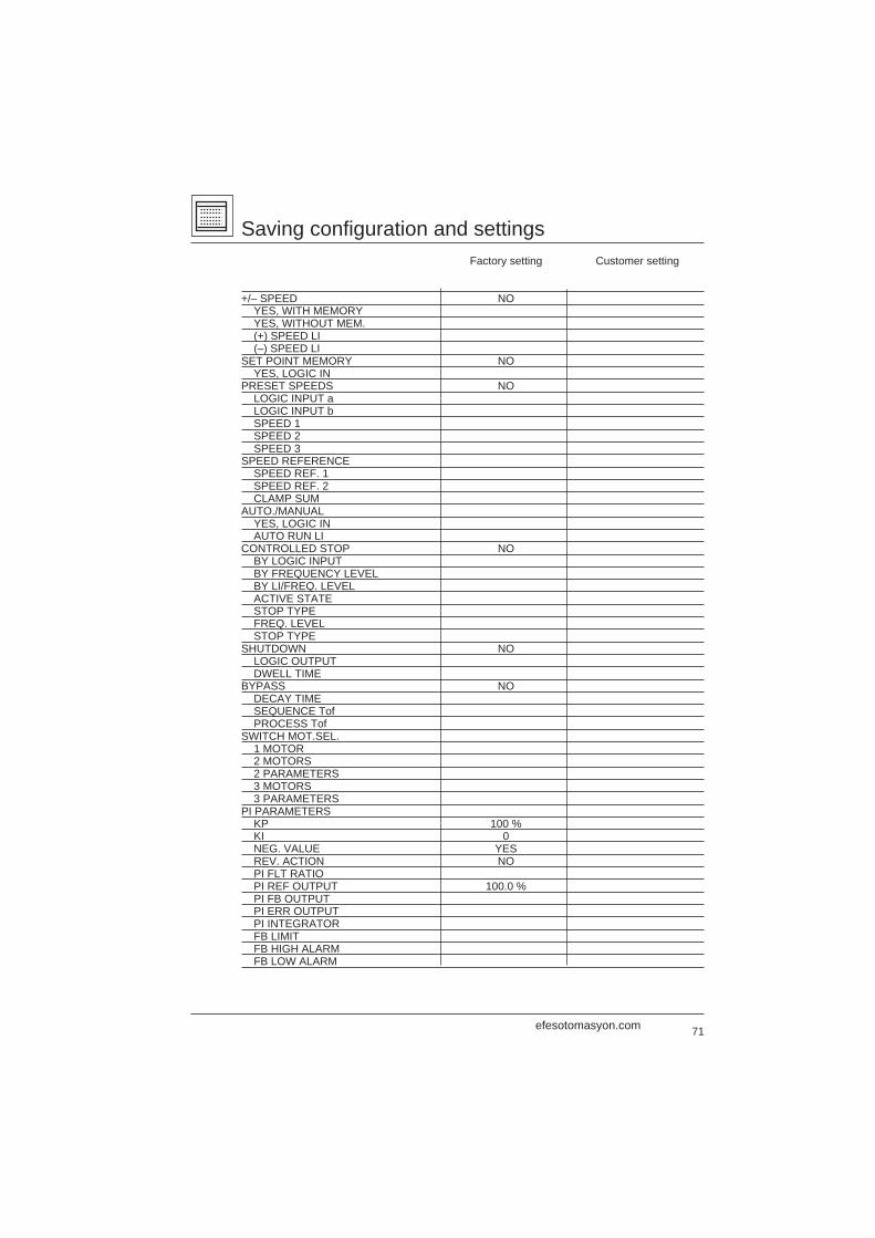
71
Saving configuration and settingsFactory setting Customer setting
+/– SPEED NOYES, WITH MEMORYYES, WITHOUT MEM.(+) SPEED LI(–) SPEED LI
SET POINT MEMORY NOYES, LOGIC IN
PRESET SPEEDS NOLOGIC INPUT aLOGIC INPUT bSPEED 1SPEED 2SPEED 3
SPEED REFERENCESPEED REF. 1SPEED REF. 2CLAMP SUM
AUTO./MANUALYES, LOGIC INAUTO RUN LI
CONTROLLED STOP NOBY LOGIC INPUTBY FREQUENCY LEVELBY LI/FREQ. LEVELACTIVE STATESTOP TYPEFREQ. LEVELSTOP TYPE
SHUTDOWN NOLOGIC OUTPUTDWELL TIME
BYPASS NODECAY TIMESEQUENCE TofPROCESS Tof
SWITCH MOT.SEL.1 MOTOR2 MOTORS2 PARAMETERS3 MOTORS3 PARAMETERS
PI PARAMETERSKP 100 %KI 0NEG. VALUE YESREV. ACTION NOPI FLT RATIOPI REF OUTPUT 100.0 %PI FB OUTPUTPI ERR OUTPUTPI INTEGRATORFB LIMITFB HIGH ALARMFB LOW ALARM
efesotomasyon.com
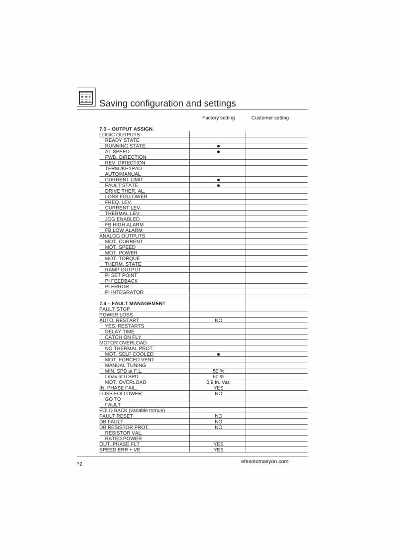
72
Saving configuration and settingsFactory setting Customer setting
7.3 – OUTPUT ASSIGN.LOGIC OUTPUTS
READY STATERUNNING STATE i
AT SPEED i
FWD. DIRECTIONREV. DIRECTIONTERM./KEYPADAUTO/MANUALCURRENT LIMIT i
FAULT STATE i
DRIVE THER. AL.LOSS FOLLOWERFREQ. LEV.CURRENT LEV.THERMAL LEV.JOG ENABLEDFB HIGH ALARMFB LOW ALARM
ANALOG OUTPUTSMOT. CURRENTMOT. SPEEDMOT. POWERMOT. TORQUETHERM. STATERAMP OUTPUTPI SET POINTPI FEEDBACKPI ERRORPI INTEGRATOR
7.4 – FAULT MANAGEMENTFAULT STOPPOWER LOSSAUTO. RESTART NO
YES, RESTARTSDELAY TIMECATCH ON FLY
MOTOR OVERLOADNO THERMAL PROT.MOT. SELF COOLED i
MOT. FORCED VENT.MANUAL TUNINGMIN. SPD at F.L. 50 %I max at 0 SPD 50 %MOT. OVERLOAD 0.9 In. Var.
IN. PHASE FAIL. YESLOSS FOLLOWER NO
GO TOFAULT
FOLD BACK (variable torque)FAULT RESET NODB FAULT NODB RESISTOR PROT. NO
RESISTOR VAL.RATED POWER
OUT. PHASE FLT YESSPEED ERR + VE YES
efesotomasyon.com

73997 1997-05 VV
DE
D39
6029
V1E
N
efesotomasyon.com
Recommended