AL-6XN® Alloy(UNS N08367)
2
Allegheny Ludlum AL-6XN® alloy (UNS N08367) isthe most corrosion resistant iron-base austenitic stain-less alloy produced by Allegheny Technologies at thistime. It is a low carbon, high purity, nitrogen-bearing"super-austenitic" stainless alloy. The AL-6XN alloy wasdesigned to be a seawater resistant material and hassince been demonstrated to be resistant to a broadrange of very corrosive environments. It is readily avail-able from stock in a wide range of product forms, in-cluding thick plate that is suitable for multi-pass weld-ing during field fabrication. The high strength and cor-rosion resistance of the AL-6XN alloy make it a betterchoice than the conventional duplex stainless steelsand a cost effective alternative to more expensivenickel-base alloys in applications where excellent form-ability, weldability, strength and corrosion resistance areessential. It is also a cost-effective alternative to lessexpensive alloys, such as Type 316, that do not havethe strength or corrosion resistance required to mini-mize life cycle costs in cer tain applications.
The high nickel and molybdenum contents provide im-proved resistance to chloride stress-corrosion crack-ing. Copper (Cu) has been intentionally kept to a re-sidual level for improved performance in seawater40.
The high alloy composition of the AL-6XN alloy re-sists crevice corrosion and pitting in oxidizing chloridesolutions to a degree previously achieved only bynickel-base alloys and titanium.
AL-6XN alloy is well suited for such applications as:• Chemical process tanks and pipelines• Process systems for offshore oil and gas platforms• Condensers, heat exchangers and piping containing
seawater or crude oil• Filter washers, vats and press rolls in pulp
bleaching plants• Power plant flue gas scrubber environments• Tall oil distillation columns and packing• Desalination equipment and pumps• Service water piping systems for nuclear
power plants• Transformer cases exposed to marine environments• Pharmaceutical equipment (for product purity)• Food processing equipment
AL-6XN® Alloy(UNS N08367)
CONTENTS
Introduction and Overview 1
Specifications 8
Applications 10
Corrosion Properties 14
Physical Properties 26
Mechanical Properties 28
Heat Treatment 32
Forming 34
Welding 38
Corrosion of Welds 43
Descaling, Pickling and Cleaning 46
References 49
Appendices
Corrosion Testing AL-6XN® Alloy 51
Detention and Removal of
Iron in Surface 53
Metallography 53
Disclaimers 54
Index 55
© 2002 Allegheny Ludlum Corporation
The Starburst Logo and AL-6XN areRegistered Trademarks of ATI Proper ties, Inc.
3
AL-6XN alloy offers the following distinct advantages:
• Corrosion Resistance
The intrinsic corrosion resistance of the AL-6XN alloyin both acidic and alkaline environments provides pro-tection against metal l ic contamination of processstreams and prevents rapid degradation of componentsmade of the alloy.
• Cost Effectiveness
The AL-6XN alloy is often a viable alternative to non-metallic materials that can provide high levels of cor-rosion resistance but are costly to install and maintain.AL-6XN alloy is significantly less costly than mostnickel-base alloys.
• Workability
The toughness and ductility of the AL-6XN alloy pro-vide for relative ease of fabrication in the shop or inthe field. The formability and weldability of the AL-6XNalloy are much better than that of high alloy ferritic orduplex stainless steels that demonstrate comparableresistance to corrosion.
• As-Welded Properties
The low carbon and high nitrogen contents in AL-6XNalloy minimize the precipitation of carbides and sec-ondary phases that can occur during welding. There-fore as-welded assemblies can be placed in service,provided that a suitable over-matched filler metal isused and the assembly has been properly cleaned.AL-6XN alloy can be welded in the field using proce-dures similar to those used with other austenitic stain-less steels.
• Wide Range of Product Forms
AL-6XN alloy is readily available in a wide range ofproduct forms, such as tube, pipe, sheet, plate, bar,billet and forgings. Components such as pumps, valves,fittings, fasteners and castings are also available.
ChemicalCompositionThe typical and specified chemical compositions ofAL-6XN alloy are presented in Table 1. The chromium,nickel and molybdenum contents are significantly higherin the AL-6XN alloy than in the standard Type 304L,316L and 317L grades. The alloy has the designationUNS N08367 and is included in appropriate standardsin the American Society for Testing and Materials(ASTM) annual book of standards. ASTM initially clas-sified AL-6XN alloy with the nonferrous alloys in the"B" specification because the alloy contains slightly lessthan 50% iron. The alloy is listed with an "N" in theUnified Number System (UNS) for the same reason.For compatibility with international standards, ASTMhas changed its definitions for steels and nickel alloys.Under these new definitions, AL-6XN alloy is now clas-sified as a steel and is listed in ASTM specification A-240 and other "A" specifications. AL-6XN alloy will,however, remain in the "B" specifications for the fore-seeable future.
The low carbon content of AL-6XN alloy distinguishesit as an "L" grade, providing high resistance to inter-granular corrosion in the as-welded condition.
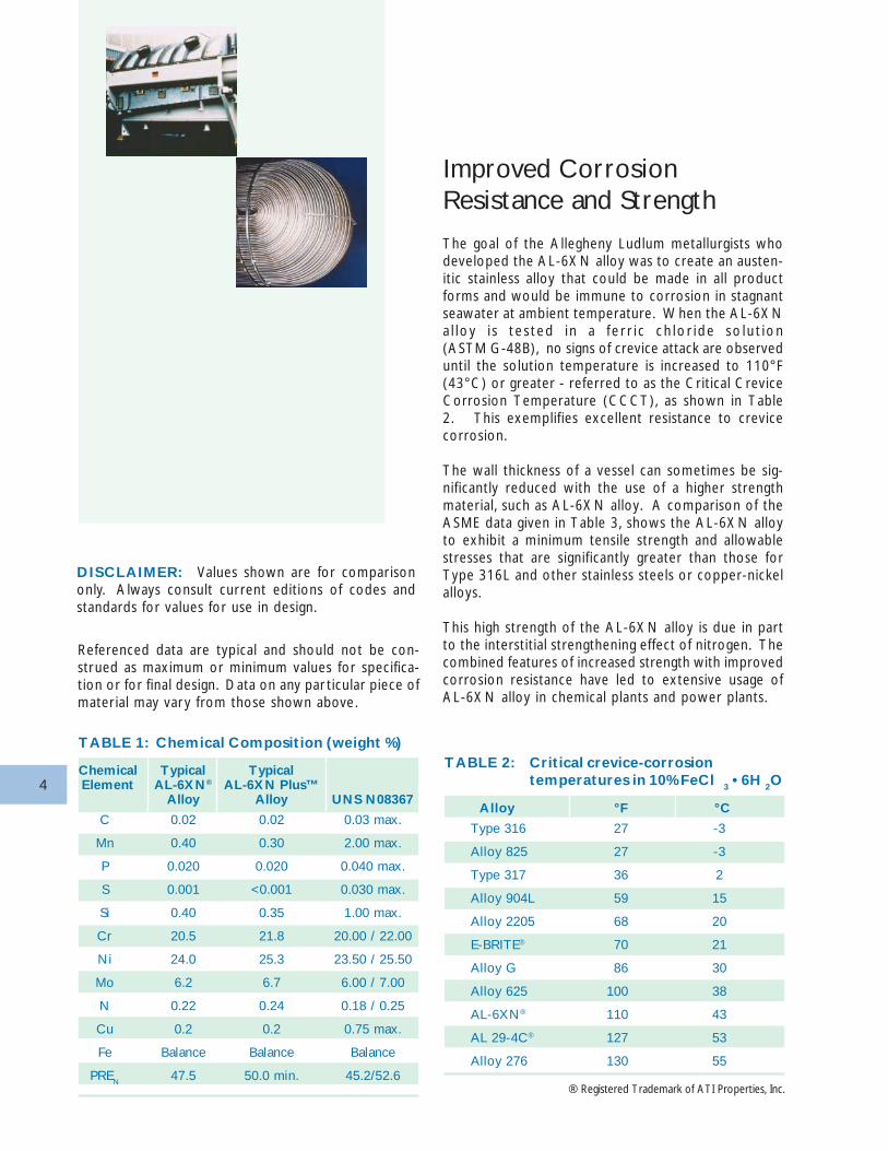
As demands placed upon AL-6XN alloy have becomemore severe, users have demanded that a higher alloyversion of AL-6XN alloy be produced. Long experi-ence in its production and diligent study of its metal-lurgy has allowed Allegheny Ludlum to produce anenhanced version of the standard AL-6XN® alloy. Thisenhanced version is called AL-6XN PLUS™ alloy. Bothversions satisfy the composition requirements of UNSN08367, but the AL-6XN PLUS alloy contains agreater concentration of the alloying elements (Cr, Mo,and N) which promote corrosion resistance. This isr e f l e c ted i n the P i t t i n g Res i s t ance Equ i va l en t(PREN = 1.0 x %Cr + 3.3 x %Mo + 30 x %N), asshown in Table 1.
™ - AL-6XN PLUS is a Trademark of ATI Proper ties, Inc.
AL-6XN PLUS alloy is custom - melted on an asordered basis, and is not available from stock.
4
Improved CorrosionResistance and Strength
The goal of the Allegheny Ludlum metallurgists whodeveloped the AL-6XN alloy was to create an austen-itic stainless alloy that could be made in all productforms and would be immune to corrosion in stagnantseawater at ambient temperature. When the AL-6XNa l loy i s t e s ted i n a f e r r i c ch lo r i de so lu t ion(ASTM G-48B), no signs of crevice attack are observeduntil the solution temperature is increased to 110°F(43°C) or greater - referred to as the Critical CreviceCorrosion Temperature (CCCT), as shown in Table2. This exemplifies excellent resistance to crevicecorrosion.
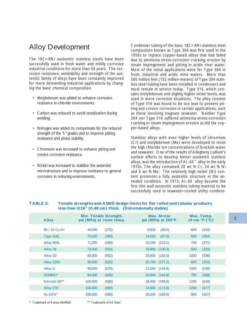
The wall thickness of a vessel can sometimes be sig-nificantly reduced with the use of a higher strengthmaterial, such as AL-6XN alloy. A comparison of theASME data given in Table 3, shows the AL-6XN alloyto exhibit a minimum tensile strength and allowablestresses that are significantly greater than those forType 316L and other stainless steels or copper-nickelalloys.
This high strength of the AL-6XN alloy is due in partto the interstitial strengthening effect of nitrogen. Thecombined features of increased strength with improvedcorrosion resistance have led to extensive usage ofAL-6XN alloy in chemical plants and power plants.
TABLE 1: Chemical Composition (weight %)
Chemical Typical TypicalElement AL-6XN® AL-6XN Plus™
Alloy Alloy UNS N08367
C 0.02 0.02 0.03 max.
Mn 0.40 0.30 2.00 max.
P 0.020 0.020 0.040 max.
S 0.001 <0.001 0.030 max.
Si 0.40 0.35 1.00 max.
Cr 20.5 21.8 20.00 / 22.00
Ni 24.0 25.3 23.50 / 25.50
Mo 6.2 6.7 6.00 / 7.00
N 0.22 0.24 0.18 / 0.25
Cu 0.2 0.2 0.75 max.
Fe Balance Balance Balance
PREN 47.5 50.0 min. 45.2/52.6
TABLE 2: Critical crevice-corrosiontemperatures in 10% FeCl 3 • 6H 2O
Alloy °F °C
Type 316 27 -3
Alloy 825 27 -3
Type 317 36 2
Alloy 904L 59 15
Alloy 2205 68 20
E-BRITE® 70 21
Alloy G 86 30
Alloy 625 100 38
AL-6XN® 110 43
AL 29-4C® 127 53
Alloy 276 130 55
® Registered Trademark of ATI Properties, Inc.
DISCLAIMER: Values shown are for comparisononly. Always consult current editions of codes andstandards for values for use in design.
Referenced data are typical and should not be con-strued as maximum or minimum values for specifica-tion or for final design. Data on any par ticular piece ofmaterial may vary from those shown above.
5
Alloy Development
The 18Cr-8Ni austenitic stainless steels have beensuccessfully used in fresh water and mildly corrosiveindustrial conditions for more than 50 years. The cor-rosion resistance, weldability and strength of the aus-tenitic family of alloys have been constantly improvedfor more demanding industrial applications by chang-ing the basic chemical composition.
• Molybdenum was added to enhance corrosionresistance in chloride environments.
• Carbon was reduced to avoid sensitization duringwelding.
• Nitrogen was added to compensate for the reducedstrength of the "L" grades and to improve pittingresistance and phase stability.
• Chromium was increased to enhance pitting andcrevice corrosion resistance.
• Nickel was increased to stabilize the austeniticmicrostructure and to improve resistance to generalcorrosion in reducing environments.
Condenser tubing of the basic 18Cr-8Ni stainless steelcomposition known as Type 304 was first used in the1950s to replace copper-based alloys that had faileddue to ammonia stress-corrosion cracking, erosion bysteam impingement and pitting in acidic river water.Most of the initial applications were for Type 304 infresh, industrial and acidic mine waters. More than500 million feet (152 million meters) of Type 304 stain-less steel tubing have been installed in condensers andmost remain in service today. Type 316, which con-tains molybdenum and slightly higher nickel levels, wasused in more corrosive situations. The alloy contentof Type 316 was found to be too lean to prevent pit-ting and crevice corrosion in certain applications, suchas those involving stagnant seawater. Neither Type304 nor Type 316 suffered ammonia stress-corrosioncracking or steam impingement erosion as did the cop-per-based alloys.
Stainless alloys with even higher levels of chromium(Cr) and molybdenum (Mo) were developed to resistthe high chloride ion concentrations of brackish waterand seawater. One of the results of Allegheny Ludlum'searliest efforts to develop better austenitic stainlessalloys, was the introduction of AL-6X™ alloy in the early1970s. The alloy contained 20 wt % Cr, 24 wt % Niand 6 wt % Mo. The relatively high nickel (Ni) con-tent promotes a fully austenitic structure in the an-nealed condition. In 1973, AL-6X alloy became thefirst thin wall austenitic stainless tubing material to besuccessfully used in seawater-cooled utility condens-
TABLE 3: Tensile strengths and ASME design limits for flat rolled and tubular productsless than 3/16” (0.48 cm) thick. (Dimensionally stable)
Min. Tensile Strength, Max. Stress Max. Temp.Alloy psi (MPa) at room temp. psi (MPa) at 200°F of use °F (°C)
90 / 10 Cu-Ni 40,000 (275) 9,500 (65.5) 600 (315)
Type 316L 70,000 (483) 14,200 (97.9) 850 (454)
Alloy 904L 71,000 (490) 16,700 (115.1) 700 (371)
Alloy 28 73,000 (503) 18,900 (130.3) 600 (315)
Alloy 20 80,000 (552) 20,600 (142.0) 1000 (538)
Alloy 2205 90,000 (620) 25,700 (177.2) 600 (315)
Alloy G 90,000 (620) 21,000 (144.8) 1000 (538)
254SMO* 94,000 (648) 23,900 (164.8) 750 (399)
Nitronic 50** 100,000 (690) 28,400 (195.8) 1200 (649)
Alloy 276 100,000 (690) 24,900 (171.6) 1250 (677)
AL-6XN® 100,000 (690) 26,200 (180.6) 800 (427)
* Trademark of Avesta Sheffield ** Trademark of AK Steel
6
ers. The original installations are still performing wellafter almost 30 years of service. More than 30 millionfeet (10 million meters) of AL-6X alloy tubing havegone into these applications, most of which involvechloride-laden cooling waters.
One significant problem with the AL-6X alloy was thatthe product forms and sizes produced were quite lim-ited for metallurgical reasons. The high chromium andmolybdenum content of the alloy rendered AL-6X al-loy susceptible to the formation of secondary (sigma)phases upon slow cooling through the 2100 to 1000°F(1150 to 540°C) temperature range. Sheet and stripproducts thicker than 0.1875 inches (4.75 mm) couldnot be cooled quickly enough to prevent the precipi-tation of secondary phases that are deleterious to cor-rosion resistance and toughness. Consequently, com-mercial AL-6X alloy products were limited to thick-nesses less than 0.10 inches (2.5 mm).
Nitrogen was found to be effective in retarding theformation and altering the morphology and distribu-tion of secondary phases. Nitrogen also enhances theeffects of chromium and molybdenum by improvingre s i s t ance to p i t t i n g , c rev i ce co r ros ion andstress-corrosion cracking.
The AL-6XN alloy was developed as an improvementover the AL-6X alloy. Both alloys have the same basicalloy composition except that the AL-6XN alloy con-tains an intentional addition of 0.18 to 0.25% N. Innew applications, AL-6XN alloy is used instead of
AL-6X alloy. Over 30 million feet (10 million meters)of thin-wall AL-6XN alloy condenser tubing are cur-rently in service. These tubes have been operatingfor periods up to 18 years in brackish or sea waters,where resistance to even minor pitting is vitally im-portant. In most of these condenser tube applications,the AL-6XN alloy replaced copper alloys and was se-lected in preference to titanium.
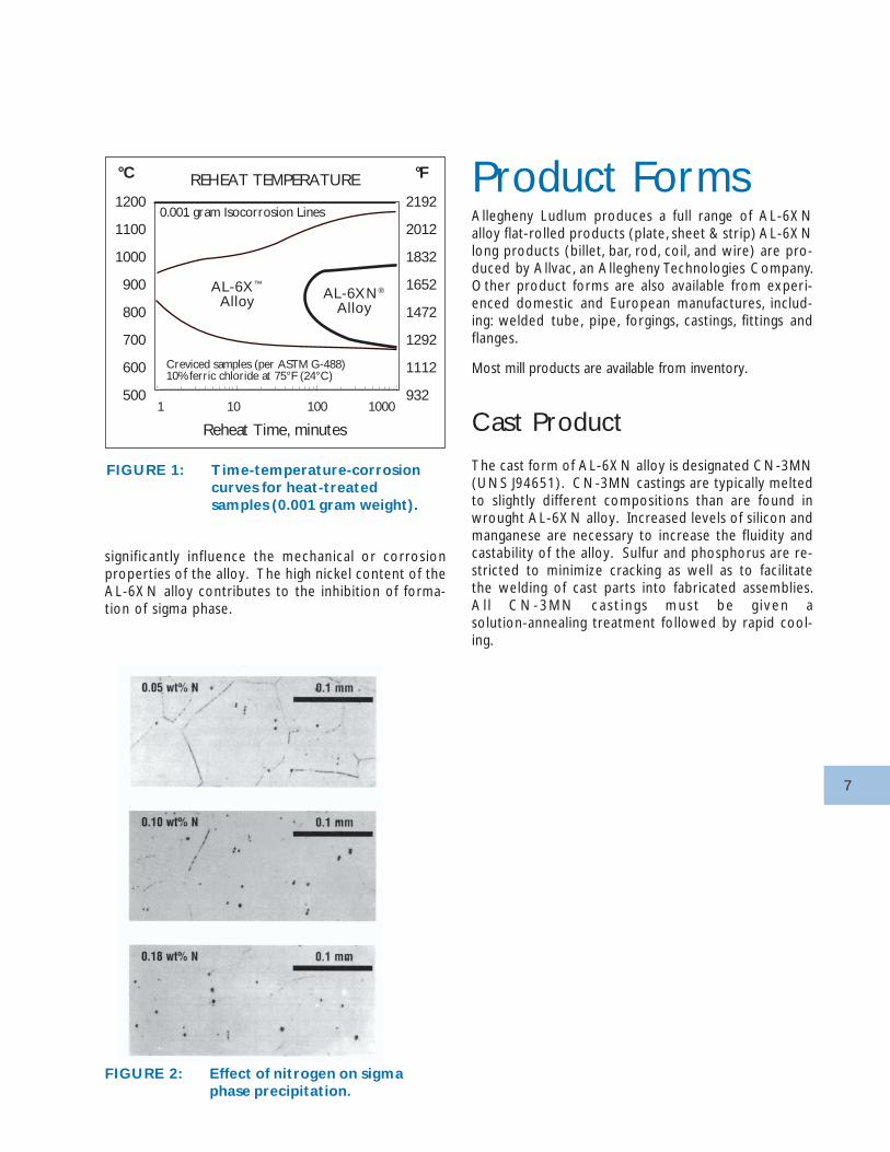
The conventional ferric chloride crevice corrosion testhas been shown to be a sensitive indicator of the pres-ence of sigma phase in high molybdenum stainlesssteels. The times at temperature needed to cause a0.001 gram weight loss from heat-treated samples ofAL-6X alloy and AL-6XN alloy exposed to 6% ferricchloride (10 wt% FeCI
3 • 6H
2O) at 75°F (21°C) are
indicated by the two curves in Figure 11. The shift inthe C-curve for the AL-6XN alloy indicates that thetime for precipitation of sigma was delayed by twoorders of magnitude relative to the nitrogen-freeAL-6X alloy. The range of aging temperatures result-ing in equivalent weight loss was also reduced by over360°F (200°C) for the AL-6XN alloy compared to theAL-6X alloy. In addition to defining the sigma precipi-tation range for these alloys. Figure 1 shows that thecrevice corrosion resistance of AL-6XN alloy is main-tained even after being exposed to a wide range oftemperatures for long periods of time.
Metallurgical Stability
The AL-6XN alloy is metallurgically stable to 950°F(510°C). On long exposures to higher temperaturesin the 1200-1800°F (650-980°C) range, sigma phasemay precipitate in grain boundaries. Sigma phase canhave an adverse effect on corrosion resistance, andthis can be correlated with metallographic appearanceof AL-6XN alloy30. Sigma phase precipitation will im-pair the corrosion resistance of AL-6XN alloy longbefore it influences mechanical properties31.
Figure 2 shows the influence of nitrogen on the for-mation of sigma phase particles on grain boundariesof a 6% Mo alloy after a 10-minute exposure at 1472°F(800°C) followed by an air cool. The intergranularprecipitates that form in the 6% Mo alloy containingonly 0.050 wt % N are not present when the nitrogencontent is raised to 0.18 wt %. This suppression ofsigma precipitation with increasing alloy nitrogen con-tent is also observed in thick plates as well as the heat-affected zones of plate welds. Traces of intermetallic(sigma) phases may be present near the centerline ofthe material. Such "centerline sigma phase" does not
7
significantly influence the mechanical or corrosionproperties of the alloy. The high nickel content of theAL-6XN alloy contributes to the inhibition of forma-tion of sigma phase.
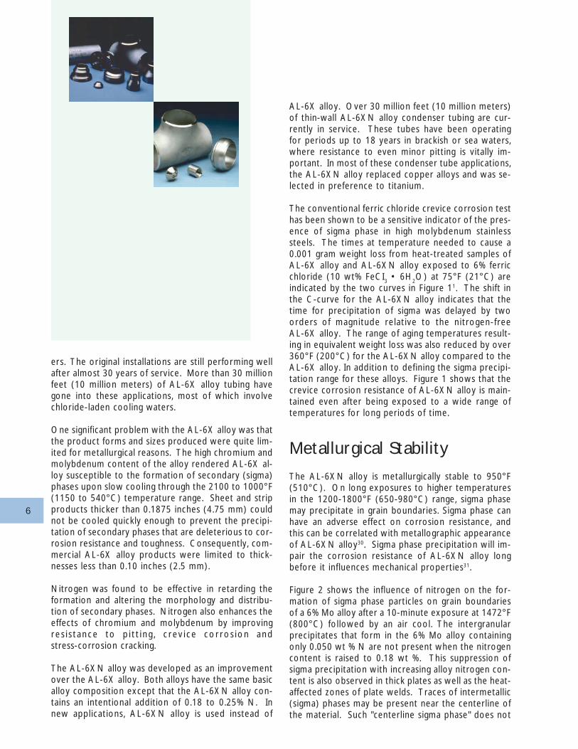
Product FormsAllegheny Ludlum produces a full range of AL-6XNalloy flat-rolled products (plate, sheet & strip) AL-6XNlong products (billet, bar, rod, coil, and wire) are pro-duced by Allvac, an Allegheny Technologies Company.Other product forms are also available from experi-enced domestic and European manufactures, includ-ing: welded tube, pipe, forgings, castings, fittings andflanges.
Most mill products are available from inventory.
Cast Product
The cast form of AL-6XN alloy is designated CN-3MN(UNS J94651). CN-3MN castings are typically meltedto slightly different compositions than are found inwrought AL-6XN alloy. Increased levels of silicon andmanganese are necessary to increase the fluidity andcastability of the alloy. Sulfur and phosphorus are re-stricted to minimize cracking as well as to facilitatethe welding of cast parts into fabricated assemblies.A l l CN-3MN ca s t i ng s mus t be g i ven asolution-annealing treatment followed by rapid cool-ing.
FIGURE 2: Effect of nitrogen on sigmaphase precipitation.
FIGURE 1: Time-temperature-corrosioncurves for heat-treatedsamples (0.001 gram weight).
AL-6XN®
Alloy
AL-6X™
Alloy
0.001 gram Isocorrosion Lines
Creviced samples (per ASTM G-488)10% ferric chloride at 75°F (24°C)
REHEAT TEMPERATURE
1 10 100 1000
Reheat Time, minutes
°F°C
1200
1100
1000
900
800
700
600
500
2192
2012
1832
1652
1472
1292
1112
932
8
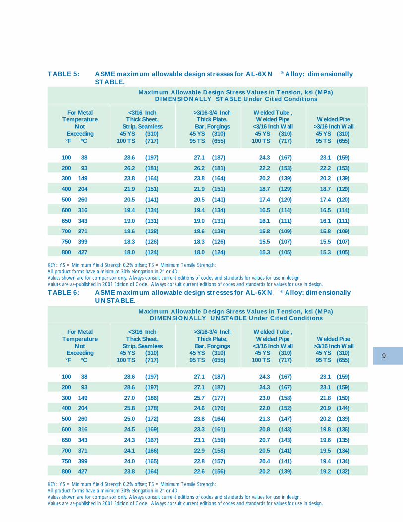
SpecificationsThe American Society for Mechanica l Engineers(ASME) and American Society for Testing and Materi-a ls (ASTM) speci f icat ions for the wide range ofAL-6XN alloy (UNS N08367) product forms are listedin Table 4. Additional coverage by various domesticand international agencies is in the process of approval.
The ASME maximum allowable design stress values formany AL-6XN alloy product forms are listed in Tables5 and 6. AL-6XN wrought product is listed in the ASMEBoiler and Pressure Vessel Code as N08367 in Sec-tion II, Part D. AL-6XN cast product is listed as J94651,CN-3MN. AL-6XN alloy is approved for use to 800°F(427°C) for Section III (Nuclear) and Section VIII Di-vision 1 (unfired pressure vessel) applications. AL-6Nalloy has been assigned to External Pressure ChartNFN-12. Use of AL-6XN alloy is allowed in the ASMECode for Pressure Piping, Sections B31.1 – Power Pip-ing – and B31.3 – Process Piping – as UNS N08367.
Note that the stress values presented in Table 6 arehigher than those in Table 5. The values in Table 6exceed 67.5% but do not exceed 90% of the yieldstrength for the alloy at the cited temperature. UsingAL-6XN alloy at these stresses is permissible accord-ing to the ASME code, but may result in dimensionalchange. The higher values are not recommended forapplications such as flanges or gasketed joints whereslight distortions can cause leakage or malfunction.
Use of AL-6XN alloy in contact with hydrogen sul-fide-containing petroleum and natural gas is approvedby NACE MR0175 for both annealed and cold workedmaterial with hardness of Rockwell C 35 or below.Norsok standard M-DP-001, Rev. 1 (December 1994)lists AL-6XN alloy as approved for use on Norwegianoffshore oil platforms.
Use of AL-6XN alloy in contact with foods has beenapproved by the U. S. Food and Drug Administration(FDA) and the National Sanitation Foundation(NSF).
TABLE 4: ASTM & ASME specificationsfor AL-6XN® (UNS N08367)Alloy Products
Product ASME ASTMPlate, Sheet and Strip SA-240, SB-688 A 240, B 688Bars and Shapes A 479Rod, Bar and Wire SB-691 B 691Bolting A 194Welded Pipe SA-358, SA-409 A 358, A409
SA-813, SA814 A 813, A 814Seamless and Welded Pipe SA-312 A 312Seamless and Welded Tube - A 269, A270
SB-829 B 829Welded Tube SA-249, SA-688 A 249, A 688
SB-676 B 676Seamless Pipe and Tube SB-690 B 690Billets and Bars for Reforging – B 472Pipe Flanges, Fittings and Valves SB-462 A 182, B 462Wrought Nickel AlloyWelded Fittings SB-366 B 366Nickel Alloy Forgings SB-564 B 564Pipe Welded with Filler SB-804 B 804Castings (CN-3MN, UNS J94651) SA-351 A 351, A 743, A744Powder Metal Product - B 834
CAUTION: Values shown are for comparison only.Always consult current editions of codes and standardsfor values for use in design.
9
TABLE 5: ASME maximum allowable design stresses for AL-6XN ® Alloy: dimensionallySTABLE.
TABLE 6: ASME maximum allowable design stresses for AL-6XN ® Alloy: dimensionallyUNSTABLE.
Maximum Allowable Design Stress Values in Tension, ksi (MPa)DIMENSIONALLY STABLE Under Cited Conditions
For Metal <3/16 Inch >3/16-3/4 Inch Welded Tube ,Temperature Thick Sheet, Thick Plate, Welded Pipe Welded Pipe
Not Strip, Seamless Bar, Forgings <3/16 Inch Wall >3/16 Inch WallExceeding 45 YS (310) 45 YS (310) 45 YS (310) 45 YS (310)°F °C 100 TS (717) 95 TS (655) 100 TS (717) 95 TS (655)
100 38 28.6 (197) 27.1 (187) 24.3 (167) 23.1 (159)
200 93 26.2 (181) 26.2 (181) 22.2 (153) 22.2 (153)
300 149 23.8 (164) 23.8 (164) 20.2 (139) 20.2 (139)
400 204 21.9 (151) 21.9 (151) 18.7 (129) 18.7 (129)
500 260 20.5 (141) 20.5 (141) 17.4 (120) 17.4 (120)
600 316 19.4 (134) 19.4 (134) 16.5 (114) 16.5 (114)
650 343 19.0 (131) 19.0 (131) 16.1 (111) 16.1 (111)
700 371 18.6 (128) 18.6 (128) 15.8 (109) 15.8 (109)
750 399 18.3 (126) 18.3 (126) 15.5 (107) 15.5 (107)
800 427 18.0 (124) 18.0 (124) 15.3 (105) 15.3 (105)
KEY: YS = Minimum Yield Strength 0.2% offset; TS = Minimum Tensile Strength;All product forms have a minimum 30% elongation in 2” or 4D.Values shown are for comparison only. Always consult current editions of codes and standards for values for use in design.Values are as-published in 2001 Edition of Code. Always consult current editions of codes and standards for values for use in design.
Maximum Allowable Design Stress Values in Tension, ksi (MPa)DIMENSIONALLY UNSTABLE Under Cited Conditions
For Metal <3/16 Inch >3/16-3/4 Inch Welded Tube ,Temperature Thick Sheet, Thick Plate, Welded Pipe Welded Pipe
Not Strip, Seamless Bar, Forgings <3/16 Inch Wall >3/16 Inch WallExceeding 45 YS (310) 45 YS (310) 45 YS (310) 45 YS (310)°F °C 100 TS (717) 95 TS (655) 100 TS (717) 95 TS (655)
100 38 28.6 (197) 27.1 (187) 24.3 (167) 23.1 (159)
200 93 28.6 (197) 27.1 (187) 24.3 (167) 23.1 (159)
300 149 27.0 (186) 25.7 (177) 23.0 (158) 21.8 (150)
400 204 25.8 (178) 24.6 (170) 22.0 (152) 20.9 (144)
500 260 25.0 (172) 23.8 (164) 21.3 (147) 20.2 (139)
600 316 24.5 (169) 23.3 (161) 20.8 (143) 19.8 (136)
650 343 24.3 (167) 23.1 (159) 20.7 (143) 19.6 (135)
700 371 24.1 (166) 22.9 (158) 20.5 (141) 19.5 (134)
750 399 24.0 (165) 22.8 (157) 20.4 (141) 19.4 (134)
800 427 23.8 (164) 22.6 (156) 20.2 (139) 19.2 (132)
KEY: YS = Minimum Yield Strength 0.2% offset; TS = Minimum Tensile Strength;All product forms have a minimum 30% elongation in 2” or 4D.Values shown are for comparison only. Always consult current editions of codes and standards for values for use in design.Values are as-published in 2001 Edition of Code. Always consult current editions of codes and standards for values for use in design.
10
ApplicationsThe applications of AL-6XN alloy described in thissection are typical examples of the uses of this highlyresistant alloy in very corrosive environments. It isnot possible to include all the applications for the al-loy, particularly since new ones are constantly beingdeveloped. The following examples are intended as aguide to show how the alloy is currently being usedand to indicate how it might be used in the future.2-9
Chemical Process
The suitability of the AISI 300 and 400 series stainlesssteel for use in the chemical process industries (CPI)has significantly changed due to:
• Increased operating temperatures and pressures
• Corrosive minor process stream constituents,particularly in closed loops
• Severe restrictions on product impurities and effluentcontents
• Demands for extended service life with minimummaintenance
• Increased cost of an unscheduled outage
• Competitive products from around the world.
More efficient and environmentally safe processes of-ten require more expensive corrosion resistant mate-rials. The AL-6XN alloy fills the gap between the cor-rosion performance of conventional Type 316 stain-less steel and nickel-base Alloy 625 or Alloy 276. Thisallows the design of systems that optimize cost andperformance.
The ideal applications for AL-6XN alloy are in envi-ronments where alloys such as Type 317 and Alloy904L fail but the expense of high nickel alloys such asAlloy 276 is not justified. The AL-6XN alloy is supe-rior to Alloy 904L, Alloy 20 and Alloy 825 in resis-tance to a broad range of corrosive environments.Strength, cost, corrosion resistance and availability ofa wide range of product forms make the AL-6XN al-loy a viable alternative to higher cost alloys such asalloys G, 625, 276 and titanium for many applications.Equipment that fails by pitting, crevice corrosion or
APPLICATIONS
Chemical Process
Pulp and Paper
Marine and Offshore
Air Pollution Control
Power
Other Applications
Biosphere
Food Processing
Residential Furnace
11
stress-corrosion cracking when fabricated from Type316 or Type 317 is substantially upgraded when re-placed by AL-6XN alloy.
Pulp and Paper
The acid stages of pulp and paper bleaching plantspresent some of the most severe industrial conditionsfor the pitting and crevice corrosion of stainless steels.Chlorine and chlorine dioxide bleaching chemicals cre-ate strongly oxidizing solutions that are very aggres-sive toward stainless steel.10-12 Seawater or contami-nated fresh water is used in various process stages ofmany plants and in closed process cycles. Tests thathave been conducted in bleaching plants1,13 have dem-onstrated that corrosion attack is less temperaturedependent for molybdenum-bearing stainless steels.Numerous cases have demonstrated that the perfor-mance of a molybdenum-bearing austenitic stainlesssteel is further improved by alloying with nitrogen.3,10
AL-6XN alloy exhibited no pitting or crevice corro-sion when exposed for one year to a "moderately se-vere chlorination-stage environment" in a pulp millbleach plant.43
The austenitic stainless alloys in most pulp bleachingplants have had molybdenum contents between 2.0and 3.5 wt % (e.g., Type 316L and Type 317L), and insome cases as high as 4.5 wt % molybdenum (Alloy904L and Type 317LX). The high alloy content of theAL-6XN alloy provides improved resistance to thio-sulfate (S
20
3-2 ), pitting corrosion and stress-corrosion
cracking (SCC) caused by chlorides, sulfur compounds,or caustic solutions. These compounds are present inwhite-water and Kraft black liquor environments andhave caused corrosion of sensitized weld heat-affectedzones in Type 304 and, in certain cases, Type 316.Intergranular SCC caused by sulfur compounds can alsooccur during the acid cleaning of sensitized stainlesssteels in Kraft liquor systems.
Process changes, such as recycling of wash water andhigher operating temperatures, have resulted in seri-ous corrosion problems in piping at many of the pulpbleaching plants currently using Type 317L pipe. Withhigher (6 wt. %) molybdenum content, the AL-6XNalloy has proven to be a significant upgrade materialfor Type 317L replacement.
Marine and Offshore
AL-6XN alloy offers resistance to many hostile off-
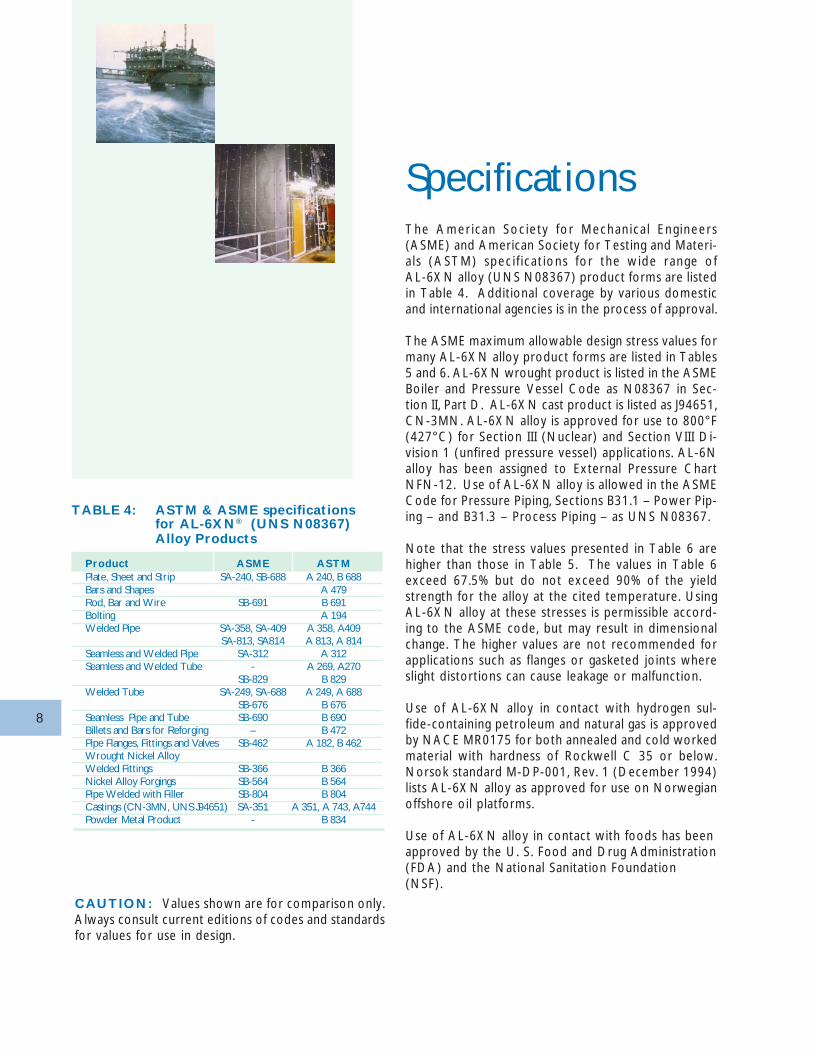
shore environments such as are found in seawater pip-ing systems (e.g., fire protection), process piping sys-tems, heat exchanger equipment, splash zones and sup-por t structures. Practical experience combined withnumbers of field trials have shown that AL-6XN alloyhas excellent resistance to crevice corrosion in sea-water, even at high temperatures, under prolongedperiods of stagnation, or with chlorination44. AL-6XNalloy has found wide application in offshore drillingplatforms and is also ideally suited for desalination sys-tems. For example, approximately 475 tons (430tonnes) of AL-6XN alloy was used by Statoil (Nor-way) on the Gullfaks platform. Over 600 tons (545tonnes) of AL-6XN alloy were used on Conoco'sHeidrun platform, also in Norway.
Air Pollution Control
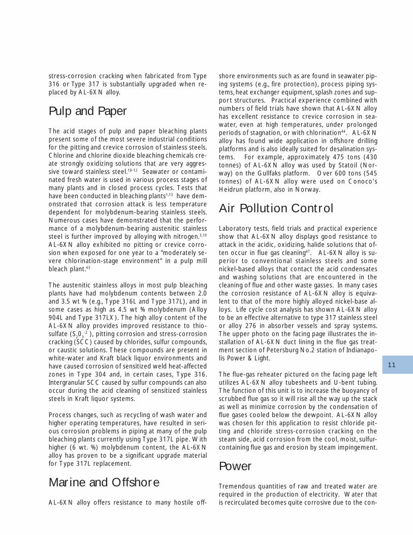
Laboratory tests, field trials and practical experienceshow that AL-6XN alloy displays good resistance toattack in the acidic, oxidizing, halide solutions that of-ten occur in flue gas cleaning47. AL-6XN alloy is su-perior to conventional stainless steels and somenickel-based alloys that contact the acid condensatesand washing solutions that are encountered in thecleaning of flue and other waste gasses. In many casesthe corrosion resistance of AL-6XN alloy is equiva-lent to that of the more highly alloyed nickel-base al-loys. Life cycle cost analysis has shown AL-6XN alloyto be an effective alternative to type 317 stainless steelor alloy 276 in absorber vessels and spray systems.The upper photo on the facing page illustrates the in-stallation of AL-6XN duct lining in the flue gas treat-ment section of Petersburg No.2 station of Indianapo-lis Power & Light.
The flue-gas reheater pictured on the facing page leftutilizes AL-6XN alloy tubesheets and U-bent tubing.The function of this unit is to increase the buoyancy ofscrubbed flue gas so it will r ise all the way up the stackas well as minimize corrosion by the condensation offlue gases cooled below the dewpoint. AL-6XN alloywas chosen for this application to resist chloride pit-ting and chlor ide stress-corrosion cracking on thesteam side, acid corrosion from the cool, moist, sulfur-containing flue gas and erosion by steam impingement.
Power
Tremendous quantities of raw and treated water arerequired in the production of electricity. Water thatis recirculated becomes quite corrosive due to the con-
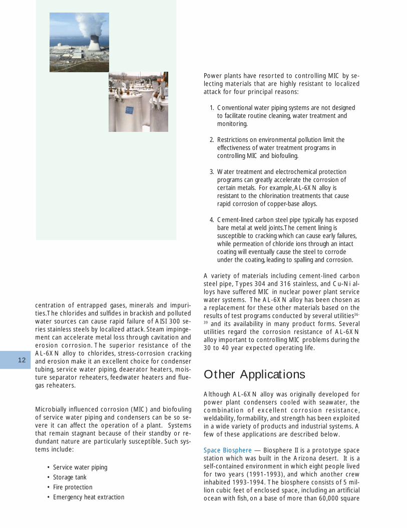
12
centration of entrapped gases, minerals and impuri-ties. The chlorides and sulfides in brackish and pollutedwater sources can cause rapid failure of AISI 300 se-ries stainless steels by localized attack. Steam impinge-ment can accelerate metal loss through cavitation anderosion corrosion. The super ior resistance of theAL-6XN alloy to chlorides, stress-corrosion crackingand erosion make it an excellent choice for condensertubing, service water piping, deaerator heaters, mois-ture separator reheaters, feedwater heaters and flue-gas reheaters.
Microbially influenced corrosion (MIC) and biofoulingof service water piping and condensers can be so se-vere it can affect the operation of a plant. Systemsthat remain stagnant because of their standby or re-dundant nature are par ticular ly susceptible. Such sys-tems include:
• Service water piping
• Storage tank
• Fire protection
• Emergency heat extraction
Power plants have resor ted to controlling MIC by se-lecting materials that are highly resistant to localizedattack for four principal reasons:
1. Conventional water piping systems are not designedto facilitate routine cleaning, water treatment andmonitoring.
2. Restrictions on environmental pollution limit theeffectiveness of water treatment programs incontrolling MIC and biofouling.
3. Water treatment and electrochemical protectionprograms can greatly accelerate the corrosion ofcertain metals. For example, AL-6XN alloy isresistant to the chlorination treatments that causerapid corrosion of copper-base alloys.
4. Cement-lined carbon steel pipe typically has exposedbare metal at weld joints. The cement lining issusceptible to cracking which can cause early failures,while permeation of chloride ions through an intactcoating will eventually cause the steel to corrodeunder the coating, leading to spalling and corrosion.
A variety of materials including cement-lined carbonsteel pipe, Types 304 and 316 stainless, and Cu-Ni al-loys have suffered MIC in nuclear power plant servicewater systems. The AL-6XN alloy has been chosen asa replacement for these other materials based on theresults of test programs conducted by several utilities36-
39 and its availability in many product forms. Severalutilities regard the corrosion resistance of AL-6XNalloy important to controlling MIC problems during the30 to 40 year expected operating life.
Other Applications
Although AL-6XN alloy was originally developed forpower plant condensers cooled with seawater, thecombinat ion o f exce l lent corros ion res i s tance ,weldability, formability, and strength has been exploitedin a wide variety of products and industrial systems. Afew of these applications are described below.
Space Biosphere — Biosphere II is a prototype spacestation which was built in the Arizona desert. It is aself-contained environment in which eight people livedfor two years (1991-1993), and which another crewinhabited 1993-1994. The biosphere consists of 5 mil-lion cubic feet of enclosed space, including an artificialocean with fish, on a base of more than 60,000 square
13
feet of AL-6XN sheet. Biosphere II was designed tohave a 100 year lifespan. AL-6XN alloy was chosenfor its weldability, resistance to corrosion by seawaterand reasonably low coefficient of thermal expansion.
Food Processing — Salt (sodium chloride) is a basicingredient of food recipes and is present in almost allfood process environments. Other aggressive chlo-rides, such as sodium hypochlorite, are found in thesolutions used to clean process units while in place.The AL-6XN alloy is used to resist hot and cold envi-ronments - from the steam used during the final stagesof food production to the brines used in cooling andchilling circuits. The AL-6XN alloy has been success-fully used to replace Type 304 and Type 316 that havefailed due to pitting, crevice corrosion and stress-cor-rosion cracking in many food process systems includ-ing brewery piping, meat cookers, cereal cookers, babyfood tanks and corn syrup refineries. According tothe United States Food and Drug Administration, theAL-6XN alloy is highly resistant as a food contact ma-terial and is not subject to food additive regulations(copy available upon request).
High Efficiency Residential Furnaces – Fuel efficienthome heating furnaces incorporate secondary heat ex-changers that condense flue gases before exhaustingthem. Crucial to the development of high efficiencyresidential furnaces is the availability of metals thatresist the acids (carbonic, nitric, sulfuric, hydrochloricand hydrofluoric acids) and halogen ions (fluorides andchlorides) that condense on heat exchanger surfaces.The AL-6XN alloy has been used for some of theseapplications because its resistance to pitting, generalcorrosion and stress-corrosion cracking is matched byexcellent cold-formability.
14
Corrosion PropertiesImpor tant design decisions are often based on corro-sion data obtained from accelerated laboratory andfield tests. Predicting actual performance in ser vicefrom such tests requires an understanding of both themetallurgical and the environmental factors that mayaffect an alloy. The factors that induce corrosion in areal process must be identified and then controlled inan accelerated test for it to be a reliable indicator ofactual performance.
The most frequent mode of failure for stainless alloysis localized corrosion induced by chlorides; specifically,pitting, crevice corrosion and stress-corrosion crack-ing. Austenitic stainless alloys can also corrode by gen-eral or intergranular modes of attack in acids and al-kalis that do not contain chlorides or other halides.Data from several laboratory and field tests are pre-sented to cover a wide range of possible process solu-tions.
Pitting
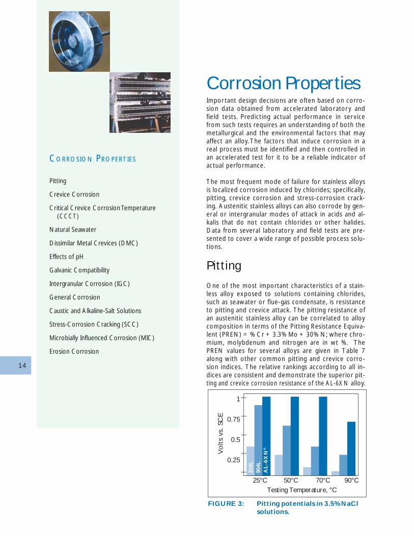
One of the most important characteristics of a stain-less alloy exposed to solutions containing chlorides,such as seawater or flue-gas condensate, is resistanceto pitting and crevice attack. The pitting resistance ofan austenitic stainless alloy can be correlated to alloycomposition in terms of the Pitting Resistance Equiva-lent (PREN) = % Cr + 3.3% Mo + 30% N; where chro-mium, molybdenum and nitrogen are in wt %. ThePREN values for several alloys are given in Table 7along with other common pitting and crevice corro-sion indices. The relative rankings according to all in-dices are consistent and demonstrate the superior pit-ting and crevice corrosion resistance of the AL-6XN alloy.
CORROSION PROPERTIES
Pitting
Crevice Corrosion
Critical Crevice Corrosion Temperature
Natural Seawater
Dissimilar Metal Crevices (DMC)
Effects of pH
Galvanic Compatibility
Intergranular Corrosion (IGC)
General Corrosion
Caustic and Alkaline-Salt Solutions
Stress-Corrosion Cracking (SCC)
Microbially Influenced Corrosion (MIC)
Erosion Corrosion
FIGURE 3: Pitting potentials in 3.5% NaClsolutions.
Testing Temperature, °C
1
0.75
0.5
0.25
25°C 50°C 70°C 90°C
Vo
lts
vs.
SCE
316L
904L
AL
-6X
N®
(CCCT)
15
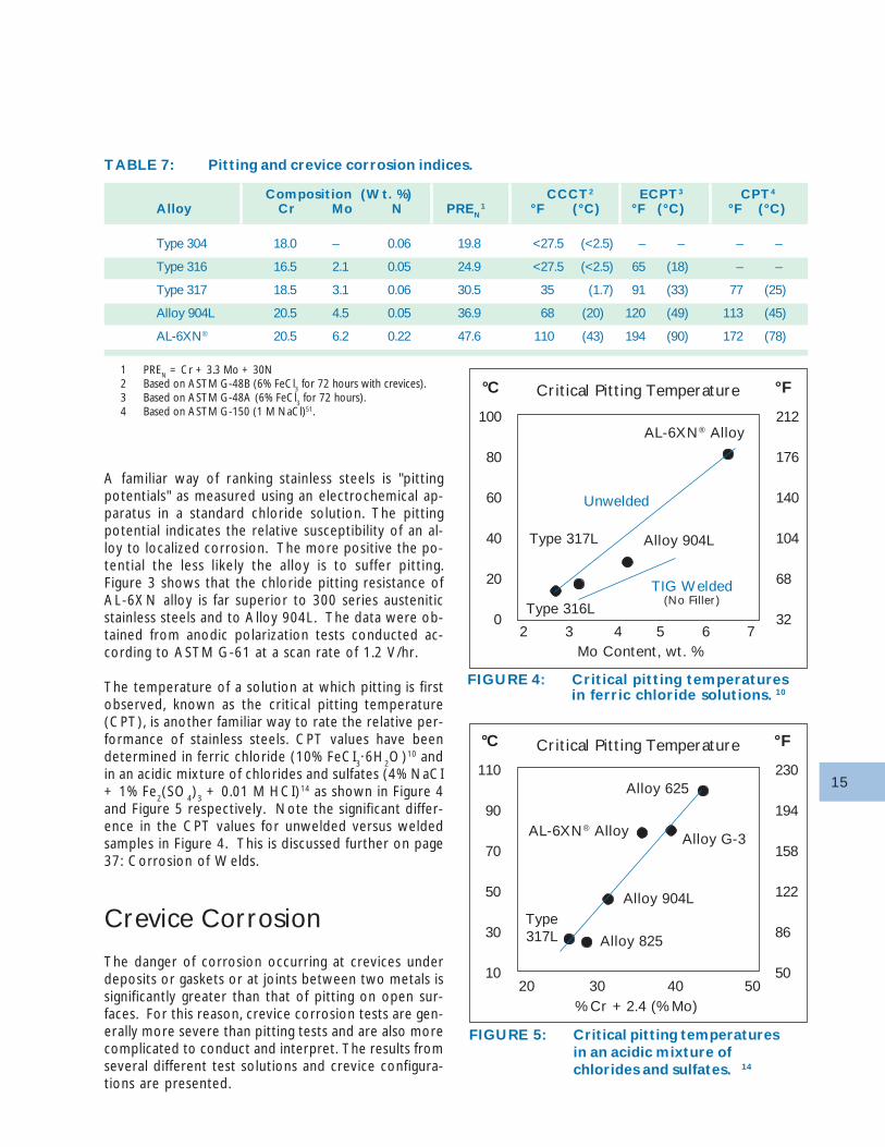
TABLE 7: Pitting and crevice corrosion indices.
Composition (Wt. %) CCCT2 ECPT3 CPT4
Alloy Cr Mo N PREN1 °F (°C) °F (°C) °F (°C)
Type 304 18.0 – 0.06 19.8 <27.5 (<2.5) – – – –
Type 316 16.5 2.1 0.05 24.9 <27.5 (<2.5) 65 (18) – –
Type 317 18.5 3.1 0.06 30.5 35 (1.7) 91 (33) 77 (25)
Alloy 904L 20.5 4.5 0.05 36.9 68 (20) 120 (49) 113 (45)
AL-6XN® 20.5 6.2 0.22 47.6 110 (43) 194 (90) 172 (78)
1 PREN = Cr + 3.3 Mo + 30N2 Based on ASTM G-48B (6% FeCl3 for 72 hours with crevices).3 Based on ASTM G-48A (6% FeCl3 for 72 hours).4 Based on ASTM G-150 (1 M NaCl)51.
FIGURE 4: Critical pitting temperaturesin ferric chloride solutions. 10
FIGURE 5: Critical pitting temperaturesin an acidic mixture ofchlorides and sulfates. 14
AL-6XN® Alloy
Unwelded
Alloy 904L
TIG Welded(No Filler)
Type 317L
Type 316L
Critical Pitting Temperature ° F°C
100
80
60
40
20
0
Mo Content, wt. %2 3 4 5 6 7
212
176
140
104
68
32
Alloy 625
Alloy G-3AL-6XN® Alloy
Alloy 904L
Alloy 825
Type317L
Critical Pitting Temperature ° F°C
110
90
70
50
30
10
230
194
158
122
86
50
% Cr + 2.4 (% Mo)20 30 40 50
A familiar way of ranking stainless steels is "pittingpotentials" as measured using an electrochemical ap-paratus in a standard chloride solution. The pittingpotential indicates the relative susceptibility of an al-loy to localized corrosion. The more positive the po-tential the less l ikely the alloy is to suffer pitting.Figure 3 shows that the chloride pitting resistance ofAL-6XN alloy is far superior to 300 series austeniticstainless steels and to Alloy 904L. The data were ob-tained from anodic polarization tests conducted ac-cording to ASTM G-61 at a scan rate of 1.2 V/hr.
The temperature of a solution at which pitting is firstobserved, known as the critical pitting temperature(CPT), is another familiar way to rate the relative per-formance of stainless steels. CPT values have beendetermined in ferric chloride (10% FeCI
3·6H
2O)10 and
in an acidic mixture of chlorides and sulfates (4% NaCI+ 1% Fe
2(SO
4)
3 + 0.01 M HCI)14 as shown in Figure 4
and Figure 5 respectively. Note the significant differ-ence in the CPT values for unwelded versus weldedsamples in Figure 4. This is discussed further on page37: Corrosion of Welds.
Crevice Corrosion
The danger of corrosion occurring at crevices underdeposits or gaskets or at joints between two metals issignificantly greater than that of pitting on open sur-faces. For this reason, crevice corrosion tests are gen-erally more severe than pitting tests and are also morecomplicated to conduct and interpret. The results fromseveral different test solutions and crevice configura-tions are presented.
16
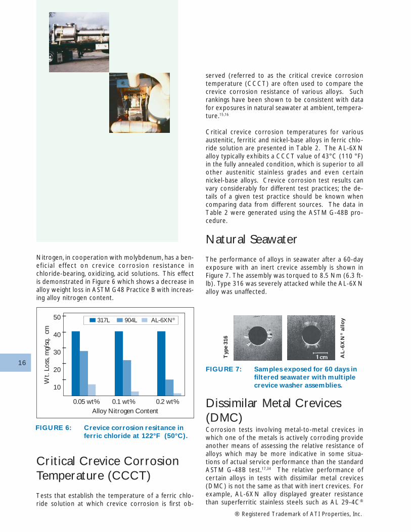
Nitrogen, in cooperation with molybdenum, has a ben-ef ic ia l e f fect on crev ice corros ion res is tance inchloride-bearing, oxidizing, acid solutions. This effectis demonstrated in Figure 6 which shows a decrease inalloy weight loss in ASTM G48 Practice B with increas-ing alloy nitrogen content.
ser ved (referred to as the critical crevice corrosiontemperature (CCCT) are often used to compare thecrevice corrosion resistance of various alloys. Suchrankings have been shown to be consistent with datafor exposures in natural seawater at ambient, tempera-ture.15,16
Critical crevice corrosion temperatures for variousaustenitic, ferritic and nickel-base alloys in ferric chlo-ride solution are presented in Table 2. The AL-6XNalloy typically exhibits a CCCT value of 43°C (110 °F)in the fully annealed condition, which is superior to allother austenitic stainless grades and even certainnickel-base alloys. Crevice corrosion test results canvary considerably for different test practices; the de-tails of a given test practice should be known whencomparing data from different sources. The data inTable 2 were generated using the ASTM G-48B pro-cedure.
Natural Seawater
The performance of alloys in seawater after a 60-dayexposure with an inert crevice assembly is shown inFigure 7. The assembly was torqued to 8.5 Nm (6.3 ft-lb). Type 316 was severely attacked while the AL-6XNalloy was unaffected.
FIGURE 6: Crevice corrosion resitance inferric chloride at 122°F (50°C).
® Registered Trademark of ATI Properties, Inc.
Critical Crevice CorrosionTemperature (CCCT)
Tests that establish the temperature of a ferric chlo-ride solution at which crevice corrosion is first ob-
FIGURE 7: Samples exposed for 60 days infiltered seawater with multiplecrevice washer assemblies.
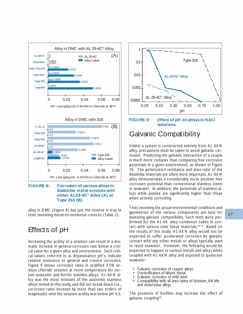
Dissimilar Metal Crevices(DMC)Corrosion tests involving metal-to-metal crevices inwhich one of the metals is actively corroding provideanother means of assessing the relative resistance ofalloys which may be more indicative in some situa-tions of actual service performance than the standardASTM G-48B test.17,34 The relative performance ofcer tain alloys in tests with dissimilar metal crevices(DMC) is not the same as that with iner t crevices. Forexample, AL-6XN alloy displayed greater resistancethan superferritic stainless steels such as AL 29-4C®
Typ
e 31
6
AL
-6X
N® a
l lo
y
Alloy Nitrogen Content
50
40
30
20
10
0.05 wt% 0.1 wt% 0.2 wt%
Wt.
Loss
, mg/
sq.
cm
317L 904L AL-6XN®
17
Galvanic Compatibility
Unless a system is constructed entirely from AL-6XNalloy, precautions must be taken to avoid galvanic cor-rosion. Predicting the galvanic interaction of a coupleis much more complex than comparing free corrosionpotentials in a given environment, as shown in Figure10. The polarization resistance and area ratio of thedissimilar materials are often more important. AL-6XNalloy demonstrates a considerably more positive freecorrosion potential than conventional stainless steelsin seawater. In addition, the potentials of stainless al-loys while passive are significantly higher than thosewhen actively corroding.
Tests involving the actual environmental conditions andgeometries of the various components are best forassessing galvanic compatibility. Such tests were per-formed for the AL-6X alloy condenser tubes in con-tact with various tube sheet materials.18,19 Based onthe results of this study, AL-6XN alloy would not beexpected to suffer accelerated corrosion by galvaniccontact with any other metals or alloys typically usedto resist seawater. However, the following would beexpected to happen to various metals and alloys whencoupled with AL-6XN alloy and exposed to quiescentseawater:
• Galvanic corrosion of copper alloys• Dezincification of Muntz metal• Galvanic corrosion of mild steel• Compatibility with all area ratios of titanium, 6% Mo
and nickel-base alloys
The presence of biofilms may increase the effect ofgalvanic coupling50.
alloy in DMC (Figure 8) but just the reverse is true intests involving metal-to-nonmetal crevices (Table 2).
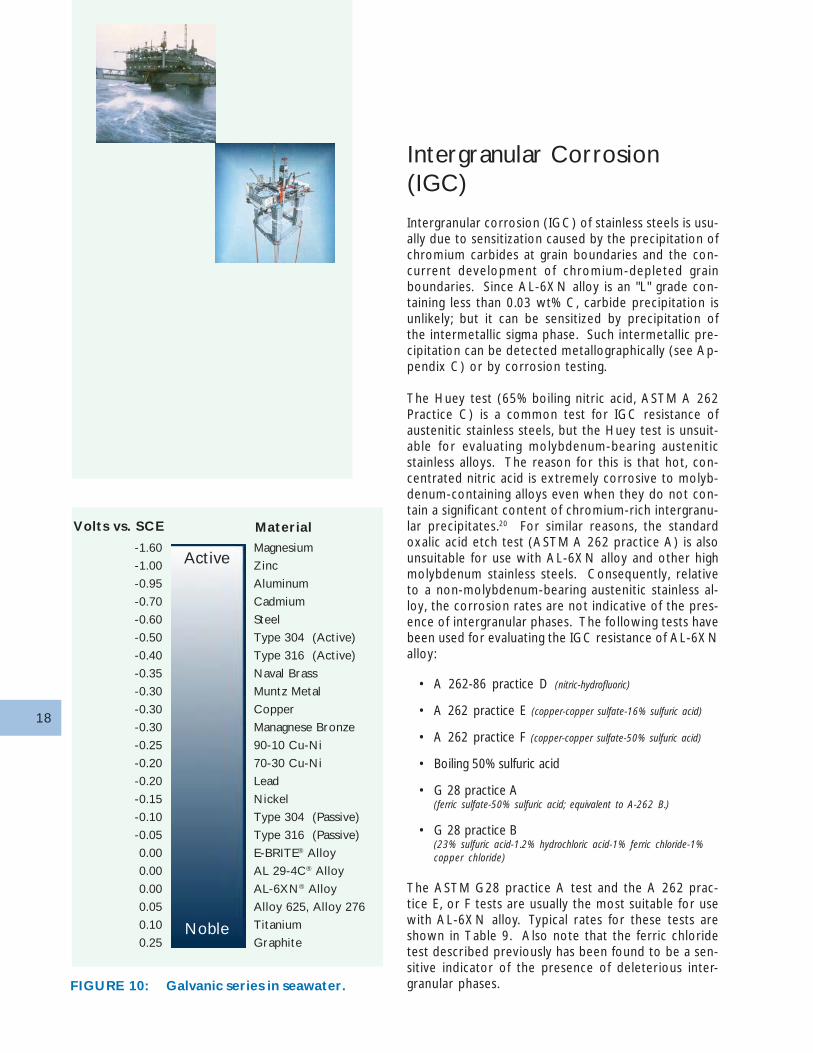
Effects of pH
Increasing the acidity of a solution can result in a dra-matic increase in general corrosion rate below a criti-cal value for a given alloy and environment. Such criti-cal values, referred to as depassivation pH's, indicaterelative resistance to general and crevice corrosion.Figure 9 shows corrosion rates in acidified 3.5% so-dium chloride solution at room temperature for cer-tain austenitic and ferritic stainless alloys. AL-6XN al-loy was the most resistant of the austenitic stainlessalloys tested in this study, and did not break down (i.e.,corrosion rates increase by more than two orders ofmagnitude) until the solution acidity was below pH 0.3.
FIGURE 8: Corrosion of various alloys indissimilar metal crevices witheither AL29-4C® Alloy (A) orType 316 (B).
FIGURE 9: Effect of pH on alloys in NaClsolutions.
0.0136
Ti (Gr 2)
Alloy 625
Alloy 600
AL-6XN®
AL 29-4C®
E-BRITE®
0 0.02 0.04 0.06 0.08
Type 316Alloy Listed
(B)
Wt. Loss (g/sq.cm) in 6% Ferric Chloride at 38°C
Alloy in DMC with 316
0.0120.0052
0.03350.0
0.0
0.0
0.0
0.0511
0.0475
0.0322
0.061
00
0.00020.0004
0.00330.0223
0.0029
0.00520.0355
0.05040.0002
AL-6XN®
Alloy 904L
Type 317LXN
Type 317L
Type 276
Type304
0.0294
0 0.02 0.04 0.06 0.08
AL 29-4CAlloy Listed
(A)
Wt. Loss (g/sq.cm) in 6% Ferric Chloride at 38°C
Alloy in DMC with AL 29-4C® Alloy
pH
1
0.1
0.01
0.001
0.0001
Type 316
AL-6XN® Alloy
AL 29-4C® Alloy
0.05 0.10 0.30 0.50 0.75 1.00
18
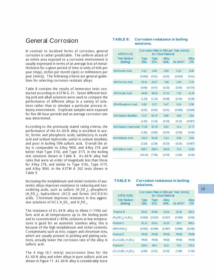
Intergranular Corrosion(IGC)
Intergranular corrosion (IGC) of stainless steels is usu-ally due to sensitization caused by the precipitation ofchromium carbides at grain boundaries and the con-current development of chromium-depleted grainboundaries. Since AL-6XN alloy is an "L" grade con-taining less than 0.03 wt% C, carbide precipitation isunlikely; but it can be sensitized by precipitation ofthe intermetallic sigma phase. Such intermetallic pre-cipitation can be detected metallographically (see Ap-pendix C) or by corrosion testing.
The Huey test (65% boiling nitric acid, ASTM A 262Practice C) is a common test for IGC resistance ofaustenitic stainless steels, but the Huey test is unsuit-able for evaluating molybdenum-bearing austeniticstainless alloys. The reason for this is that hot, con-centrated nitric acid is extremely corrosive to molyb-denum-containing alloys even when they do not con-tain a significant content of chromium-rich intergranu-lar precipitates.20 For similar reasons, the standardoxalic acid etch test (ASTM A 262 practice A) is alsounsuitable for use with AL-6XN alloy and other highmolybdenum stainless steels. Consequently, relativeto a non-molybdenum-bearing austenitic stainless al-loy, the corrosion rates are not indicative of the pres-ence of intergranular phases. The following tests havebeen used for evaluating the IGC resistance of AL-6XNalloy:
• A 262-86 practice D (nitric-hydrofluoric)
• A 262 practice E (copper-copper sulfate-16% sulfuric acid)
• A 262 practice F (copper-copper sulfate-50% sulfuric acid)
• Boiling 50% sulfuric acid
• G 28 practice A(ferric sulfate-50% sulfuric acid; equivalent to A-262 B.)
• G 28 practice B(23% sulfuric acid-1.2% hydrochloric acid-1% ferric chloride-1%copper chloride)
The ASTM G28 practice A test and the A 262 prac-tice E, or F tests are usually the most suitable for usewith AL-6XN alloy. Typical rates for these tests areshown in Table 9. Also note that the ferric chloridetest described previously has been found to be a sen-sitive indicator of the presence of deleterious inter-granular phases.FIGURE 10: Galvanic series in seawater.
Magnesium
Zinc
Aluminum
Cadmium
Steel
Type 304 (Active)
Type 316 (Active)
Naval Brass
Muntz Metal
Copper
Managnese Bronze
90-10 Cu-Ni
70-30 Cu-Ni
Lead
Nickel
Type 304 (Passive)
Type 316 (Passive)
E-BRITE® Alloy
AL 29-4C® Alloy
AL-6XN® Alloy
Alloy 625, Alloy 276
Titanium
Graphite
Active
Noble
Material
-1.60
-1.00
-0.95
-0.70
-0.60
-0.50
-0.40
-0.35
-0.30
-0.30
-0.30
-0.25
-0.20
-0.20
-0.15
-0.10
-0.05
0.00
0.00
0.00
0.05
0.10
0.25
Volts vs. SCE
19
General Corrosion
In contrast to localized forms of corrosion, generalcorrosion is rather predictable. The uniform attack ofan entire area exposed to a corrosive environment isusually expressed in terms of an average loss-of-metal-thickness for a given period of time in units of mils peryear (mpy), inches per month (ipm) or millimeters peryear (mm/y). The following criteria are general guide-lines for selecting corrosion resistant alloys:
Table 8 contains the results of immersion tests con-ducted according to ASTM G-31. Seven different boil-ing acid and alkali solutions were used to compare theperformance of different alloys in a variety of solu-tions rather than to simulate a particular process in-dustry environment. Duplicate samples were exposedfor five 48-hour periods and an average corrosion ratewas determined.
According to the previously stated rating criteria, theperformance of the AL-6XN alloy is excellent in ace-tic, formic and phosphoric acids; satisfactory in oxalicacid and sodium hydroxide; useful in sodium bisulfate;and poor in boiling 10% sulfuric acid. Overall the al-loy is comparable to Alloy 904L and Alloy 276 andbetter than Type 316L and Type 317L in the boilingtest solutions shown in Table 8. AL-6XN alloy hadrates that were an order of magnitude less than thosefor Alloy 276, and similar to Type 316L, Type 317Land Alloy 904L in the ASTM A 262 tests shown inTable 9.
Increasing the molybdenum and nickel contents of aus-tenitic alloys improves resistance to reducing and non-oxidizing acids, such as sulfuric (H
2SO
4), phosphoric
(H3PO
4), hydrochloric (HCI) and formic (HCOOH)
acids. Chromium improves resistance in less aggres-sive solutions of HCI, H
2SO
4 and H
3PO
4.
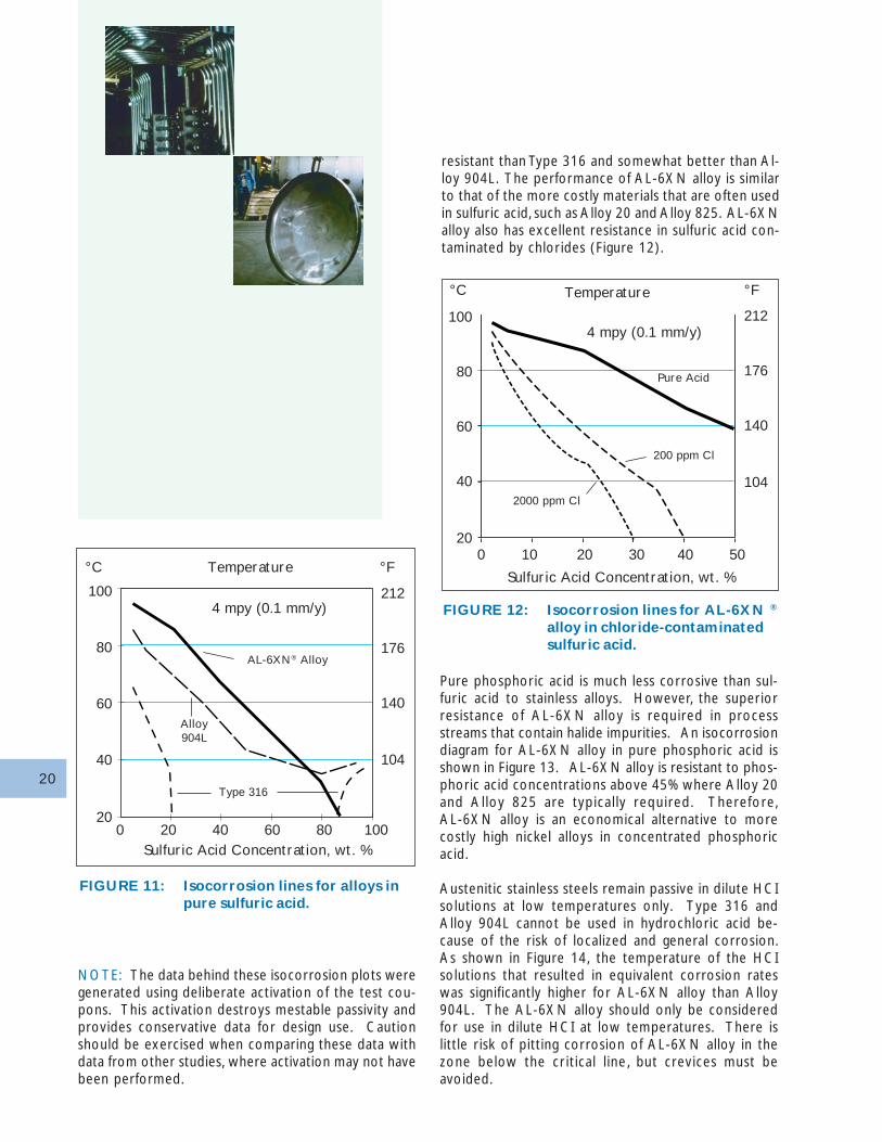
The resistance of AL-6XN alloy to dilute (<15%) sul-furic acid at all temperatures up to the boiling pointand to concentrated (>85%) solutions at low tempera-tures is good for an austenitic stainless alloy; this isbecause of the high molybdenum and nickel contents.Contaminants such as iron, copper and chromium ions,which are usually present in pickling and plating solu-tions, actually lower the corrosion rate of the alloy insulfuric acid.
The 4 mpy (0.1 mm/y) isocorrosion l ines for theAL-6XN alloy and other alloys in pure sulfuric acid areshown in Figure 11. AL-6XN alloy is considerably more
TABLE 9: Corrosion resistance in boilingsolutions.
Corrosion Rate in Mils per Year (mm/y)ASTM G-31 for Cited Material
TABLE 8: Corrosion resistance in boilingsolutions.
Test Solution Type Type Alloy Alloy(Boiling) 316L 317L 904L AL-6XN® 276
20% Acetic Acid 0.12 0.48 0.59 0.12 0.48
(0.003) (0.01) (0.02) (0.003) (0.01)
45% Formic Acid 23.41 18.37 7.68 2.40 2.76
(0.60) (0.47) (0.20) (0.06) (0.070)
10% Oxalic Acid 44.90 48.03 27.13 7.32 11.24
(1.23) (1.14) (0.69) (0.19) (0.28)
20% Phosphoric Acid 0.60 0.72 0.47 0.24 0.36
(0.02) (0.02) (0.01) (0.006) (0.009)
10% Sodium Bisulfate 71.57 55.76 8.88 4.56 2.64
(1.82) (1.42) (0.23) (0.12) (0.067)
50% Sodium Hydroxide 77.69 32.78 9.61 11.4 17.77
(1.92) (0.83) (0.24) (0.29) (0.45)
10% Sulfamic Acid 124.3 93.26 9.13 9.36 2.64
(3.16) (2.39) (0.23) (0.24) (0.067)
10% Sulfuric Acid 635.7 298.3 100.8 71.9 13.93
(16.15) (7.58) (2.53) (1.83) (0.35)
Corrosion Rate in Mils per Year (mm/y)ASTM A262 for Cited MaterialTest Solution Type Type Alloy Alloy
(Boiling) 316L 317L 904L AL-6XN® 276
Practice B 25.81 20.58 14.04 15.35 262.2
(Fe2(SO4)3-H2SO4) (0.656) (0.523) (0.357) (0.390) (6.66)
Practice C 22.12 19.51 15.23 26.2 900.1
(65% HNO3) (0.562) (0.496) (0.387) (0.666) (22.86)
Practice E PASS PASS PASS PASS PASS
(Cu-CuSO4-H2SO4) PASS PASS PASS PASS PASS
Practice F 106.0 99.0 91.8 74.2 275.5
(Cu-CuSO4-H2SO4) (2.69) (2.51) (2.33) (1.88) (7.00)
20
resistant than Type 316 and somewhat better than Al-loy 904L. The performance of AL-6XN alloy is similarto that of the more costly materials that are often usedin sulfuric acid, such as Alloy 20 and Alloy 825. AL-6XNalloy also has excellent resistance in sulfuric acid con-taminated by chlorides (Figure 12).
FIGURE 11: Isocorrosion lines for alloys inpure sulfuric acid.
FIGURE 12: Isocorrosion lines for AL-6XN ®
alloy in chloride-contaminatedsulfuric acid.
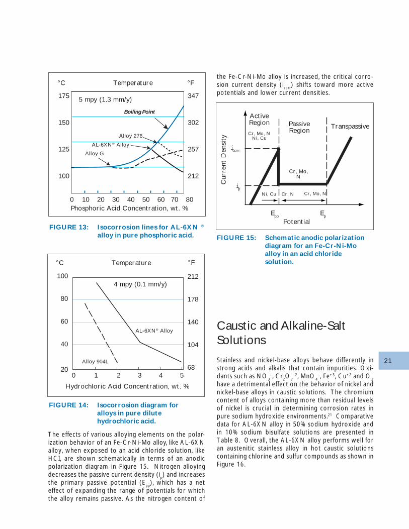
Pure phosphoric acid is much less corrosive than sul-furic acid to stainless alloys. However, the superiorresistance of AL-6XN alloy is required in processstreams that contain halide impurities. An isocorrosiondiagram for AL-6XN alloy in pure phosphoric acid isshown in Figure 13. AL-6XN alloy is resistant to phos-phoric acid concentrations above 45% where Alloy 20and Alloy 825 are typical ly required. Therefore,AL-6XN alloy is an economical alternative to morecostly high nickel alloys in concentrated phosphoricacid.
Austenitic stainless steels remain passive in dilute HCIsolutions at low temperatures only. Type 316 andAlloy 904L cannot be used in hydrochloric acid be-cause of the risk of localized and general corrosion.As shown in Figure 14, the temperature of the HCIsolutions that resulted in equivalent corrosion rateswas significantly higher for AL-6XN alloy than Alloy904L. The AL-6XN alloy should only be consideredfor use in dilute HCI at low temperatures. There islittle risk of pitting corrosion of AL-6XN alloy in thezone below the cr itical l ine , but crevices must beavoided.
NOTE: The data behind these isocorrosion plots weregenerated using deliberate activation of the test cou-pons. This activation destroys mestable passivity andprovides conservative data for design use. Cautionshould be exercised when comparing these data withdata from other studies, where activation may not havebeen performed.
100
80
60
40
20
Sulfuric Acid Concentration, wt. %
212
176
140
104
0 10 20 30 40 50
°C °FTemperature
200 ppm Cl
2000 ppm Cl
Pure Acid
4 mpy (0.1 mm/y)
100
80
60
40
20
212
176
140
104
0 20 40 60 80 100
°C °FTemperature
Sulfuric Acid Concentration, wt. %
Type 316
Alloy904L
AL-6XN® Alloy
4 mpy (0.1 mm/y)
21
FIGURE 13: Isocorrosion lines for AL-6XN ®
alloy in pure phosphoric acid.
FIGURE 14: Isocorrosion diagram foralloys in pure dilutehydrochloric acid.
FIGURE 15: Schematic anodic polarizationdiagram for an Fe-Cr-Ni-Moalloy in an acid chloridesolution.
The effects of various alloying elements on the polar-ization behavior of an Fe-Cr-Ni-Mo alloy, like AL-6XNalloy, when exposed to an acid chloride solution, likeHCI, are shown schematically in terms of an anodicpolarization diagram in Figure 15. Nitrogen alloyingdecreases the passive current density (i
p) and increases
the primary passive potential (Epp
), which has a neteffect of expanding the range of potentials for whichthe alloy remains passive. As the nitrogen content of
the Fe-Cr-Ni-Mo alloy is increased, the critical corro-sion current density (i
corr) shifts toward more active
potentials and lower current densities.
Caustic and Alkaline-SaltSolutions
Stainless and nickel-base alloys behave differently instrong acids and alkalis that contain impurities. Oxi-dants such as NO
3–, Cr
2O
7–2, MnO
4–, Fe+3, Cu+2 and O
2
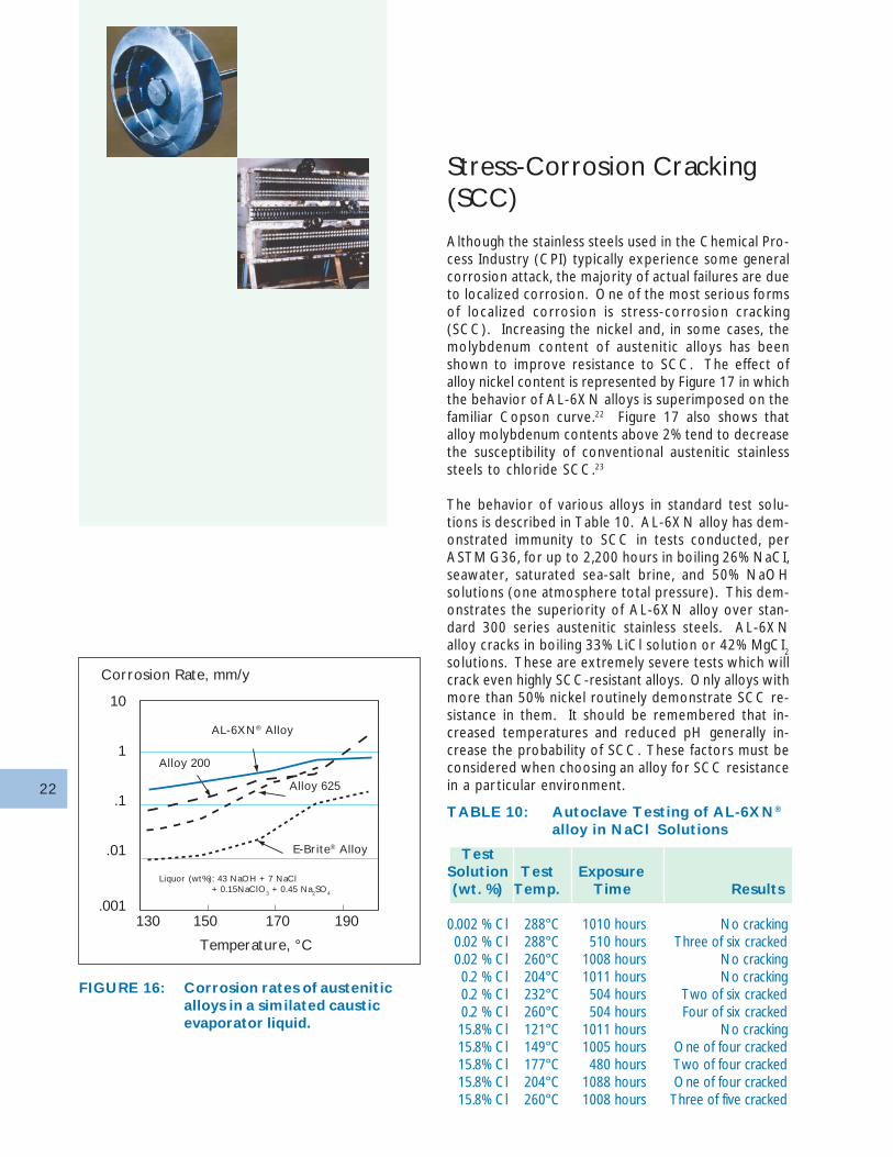
have a detrimental effect on the behavior of nickel andnickel-base alloys in caustic solutions. The chromiumcontent of alloys containing more than residual levelsof nickel is crucial in determining corrosion rates inpure sodium hydroxide environments.21 Comparativedata for AL-6XN alloy in 50% sodium hydroxide andin 10% sodium bisulfate solutions are presented inTable 8. Overall, the AL-6XN alloy performs well foran austenitic stainless alloy in hot caustic solutionscontaining chlorine and sulfur compounds as shown inFigure 16.
100
80
60
40
20
212
178
140
104
680 1 2 3 4 5
°C °FTemperature
Hydrochloric Acid Concentration, wt. %
Alloy 904L
AL-6XN® Alloy
4 mpy (0.1 mm/y)
Potential
icorr
ip
ActiveRegion
Cr, Mo, NNi, Cu
PassiveRegion
Transpassive
Cr, Mo,N
Ni, Cu Cr, N Cr, Mo, N
Epp Ep
Cur
rent
Den
sity
175
150
125
100
347
302
257
212
0 10 20 30 40 50 60 70 80
°C °FTemperature
Phosphoric Acid Concentration, wt. %
Alloy G
AL-6XN® Alloy
5 mpy (1.3 mm/y)
Alloy 276
Boiling Point
22
Stress-Corrosion Cracking(SCC)
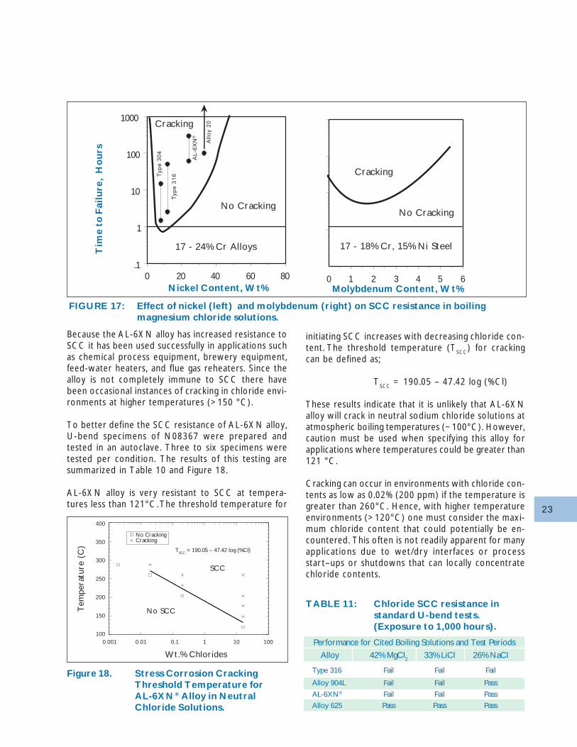
Although the stainless steels used in the Chemical Pro-cess Industry (CPI) typically experience some generalcorrosion attack, the majority of actual failures are dueto localized corrosion. One of the most serious formsof localized corrosion is stress-corrosion cracking(SCC). Increasing the nickel and, in some cases, themolybdenum content of austenitic alloys has beenshown to improve resistance to SCC. The effect ofalloy nickel content is represented by Figure 17 in whichthe behavior of AL-6XN alloys is superimposed on thefamiliar Copson curve.22 Figure 17 also shows thatalloy molybdenum contents above 2% tend to decreasethe susceptibility of conventional austenitic stainlesssteels to chloride SCC.23
The behavior of various alloys in standard test solu-tions is described in Table 10. AL-6XN alloy has dem-onstrated immunity to SCC in tests conducted, perASTM G36, for up to 2,200 hours in boiling 26% NaCI,seawater, saturated sea-salt brine, and 50% NaOHsolutions (one atmosphere total pressure). This dem-onstrates the superiority of AL-6XN alloy over stan-dard 300 series austenitic stainless steels. AL-6XNalloy cracks in boiling 33% LiCl solution or 42% MgCI
2
solutions. These are extremely severe tests which willcrack even highly SCC-resistant alloys. Only alloys withmore than 50% nickel routinely demonstrate SCC re-sistance in them. It should be remembered that in-creased temperatures and reduced pH generally in-crease the probability of SCC. These factors must beconsidered when choosing an alloy for SCC resistancein a par ticular environment.
FIGURE 16: Corrosion rates of austeniticalloys in a similated causticevaporator liquid.
TestSolution Test Exposure(wt. %) Temp. Time Results
0.002 % Cl 288°C 1010 hours No cracking0.02 % Cl 288°C 510 hours Three of six cracked0.02 % Cl 260°C 1008 hours No cracking0.2 % Cl 204°C 1011 hours No cracking0.2 % Cl 232°C 504 hours Two of six cracked0.2 % Cl 260°C 504 hours Four of six cracked15.8% Cl 121°C 1011 hours No cracking15.8% Cl 149°C 1005 hours One of four cracked15.8% Cl 177°C 480 hours Two of four cracked15.8% Cl 204°C 1088 hours One of four cracked15.8% Cl 260°C 1008 hours Three of five cracked
TABLE 10: Autoclave Testing of AL-6XN®
alloy in NaCl Solutions
10
1
.1
.01
.001130 150 170 190
Corrosion Rate, mm/y
Temperature, °C
Alloy 200
AL-6XN® Alloy
Alloy 625
E-Brite® Alloy
Liquor (wt%): 43 NaOH + 7 NaCl+ 0.15NaClO3 + 0.45 Na2SO4
23
Because the AL-6XN alloy has increased resistance toSCC it has been used successfully in applications suchas chemical process equipment, brewery equipment,feed-water heaters, and flue gas reheaters. Since thealloy is not completely immune to SCC there havebeen occasional instances of cracking in chloride envi-ronments at higher temperatures (>150 °C).
To better define the SCC resistance of AL-6XN alloy,U-bend specimens of N08367 were prepared andtested in an autoclave. Three to six specimens weretested per condition. The results of this testing aresummarized in Table 10 and Figure 18.
AL-6XN alloy is very resistant to SCC at tempera-tures less than 121°C. The threshold temperature for
Figure 18. Stress Corrosion CrackingThreshold Temperature forAL-6XN® Alloy in NeutralChloride Solutions.
initiating SCC increases with decreasing chloride con-tent. The threshold temperature (T
SCC) for cracking
can be defined as;
TSCC
= 190.05 – 47.42 log (%Cl)
These results indicate that it is unlikely that AL-6XNalloy will crack in neutral sodium chloride solutions atatmospheric boiling temperatures (~100°C). However,caution must be used when specifying this alloy forapplications where temperatures could be greater than121 °C.
Cracking can occur in environments with chloride con-tents as low as 0.02% (200 ppm) if the temperature isgreater than 260°C. Hence, with higher temperatureenvironments (>120°C) one must consider the maxi-mum chloride content that could potentially be en-countered. This often is not readily apparent for manyapplications due to wet/dr y interfaces or processstar t–ups or shutdowns that can locally concentratechloride contents.
FIGURE 17: Effect of nickel (left) and molybdenum (right) on SCC resistance in boilingmagnesium chloride solutions.
400
350
300
250
200
150
100
TABLE 11: Chloride SCC resistance instandard U-bend tests.(Exposure to 1,000 hours).
Performance for Cited Boiling Solutions and Test Periods
Alloy 42% MgCl2 33% LiCl 26% NaCl
Type 316 Fail Fail Fail
Alloy 904L Fail Fail Pass
AL-6XN® Fail Fail Pass
Alloy 625 Pass Pass Pass
806040200.1
1
10
100
1000
6543210Nickel Content, Wt% Molybdenum Content, Wt%
Tim
e t
o F
ailu
re,
Ho
urs
Cracking
No Cracking
Cracking
No Cracking
17 - 24% Cr Alloys 17 - 18% Cr, 15% Ni Steel
All
oy
20
AL
-6X
N®
Typ
e 3
16T
ype
30
4
Wt.% Chlorides
Tem
pera
ture
(C
)
0.001 0.01 0.1 1 10 100
No SCC
SCC
No CrackingCracking
TSCC = 190.05 – 47.42 log (%Cl)
24
Microbially InfluencedCorrosion (MIC)
Although MIC has been studied for over seventy years,the full impact of microorganisms on the degradationof metallic structures has only recently begun to beappreciated in many industries. Corrosion rates havebeen observed to increase by two and three orders ofmagnitude due to the activity of microbes and depos-its on metal surfaces. A review of service experienceswith stainless steels has concluded that no instancesof MIC have been reported for 6% Mo alloys42.
MIC is not a new form of corrosion, but some of theconditions created by microbes are unique. Microbescan directly participate in electrochemical reactions thatmake an environment much more corrosive. Certainmicrobes can metabolize nutrients using oxygen orother chemical compounds (e.g., sulfur and iron) andgenerate corrosive agents (e.g., organic acids and sul-fides) as well as create a "living crevice." The mecha-nism for MIC is related to that for crevice corrosion.MIC is often associated with biofouling. Deposits ofgelatinous slime and other debris can cover an other-wise open surface and effectively increase the poten-tial at the surface by as much as 400 mV. In suchcases, a passive metal surface is prone to attack at lo-calized sites where bare metal is exposed through thefouling layer. * Pitting was observed
TABLE 12: Resistance to a simulated MICenvironment (2% NaCl + KMnO4).
Results of duplicate specimentesting.
Temp. °F (°C) Weight Loss, mg/cm2
77°F 122°F 167°F 194°FAlloy (25°C) (50°C) (75°C) (90°C)
Type 316 0.01 0.03 6.99* –
(0.02) (0.04) (0.12) –
AL-6XN® 0.01 0.03 0.06 0.04
(0.01) (0.03) (0.05) (0.03)
The three major types of microbes commonly associ-ated with MIC are sulfate reducing bacteria (SRB), ironand manganese bacteria and sulfur oxidizing bacteria.Iron and manganese oxidizing bacteria are the typesmost often associated with the corrosion of stainlesssteels. Such bacteria produce iron and manganesemetabolites that form deposits. Temperatures greaterthan 40°F (4°C) but less than 140°F (60°C) tend topromote MIC.
AL-6XN alloy is superior to Type 316 in a laboratoryimmersion test that chemically simulates an environ-ment created by bacteria that concentrate manganeseon heat exchanger tubing cooled by river water thathas been chlorinated to prevent biofouling (Table 12).25
A simple immersion test does not simulate the dynam-ics of microbial consortia in actual service environ-ments. However, reliable methods for predicting thesusceptibility of materials to MIC have yet to be de-veloped.
Microbial growths can be controlled by chemical treat-ments, rigorous monitoring and maintenance. In cer-tain cases, highly oxidizing biocides such as chlorinecan elevate the potential of a system to a level thatmight induce corrosion of the metal surfaces that arebeing cleaned.
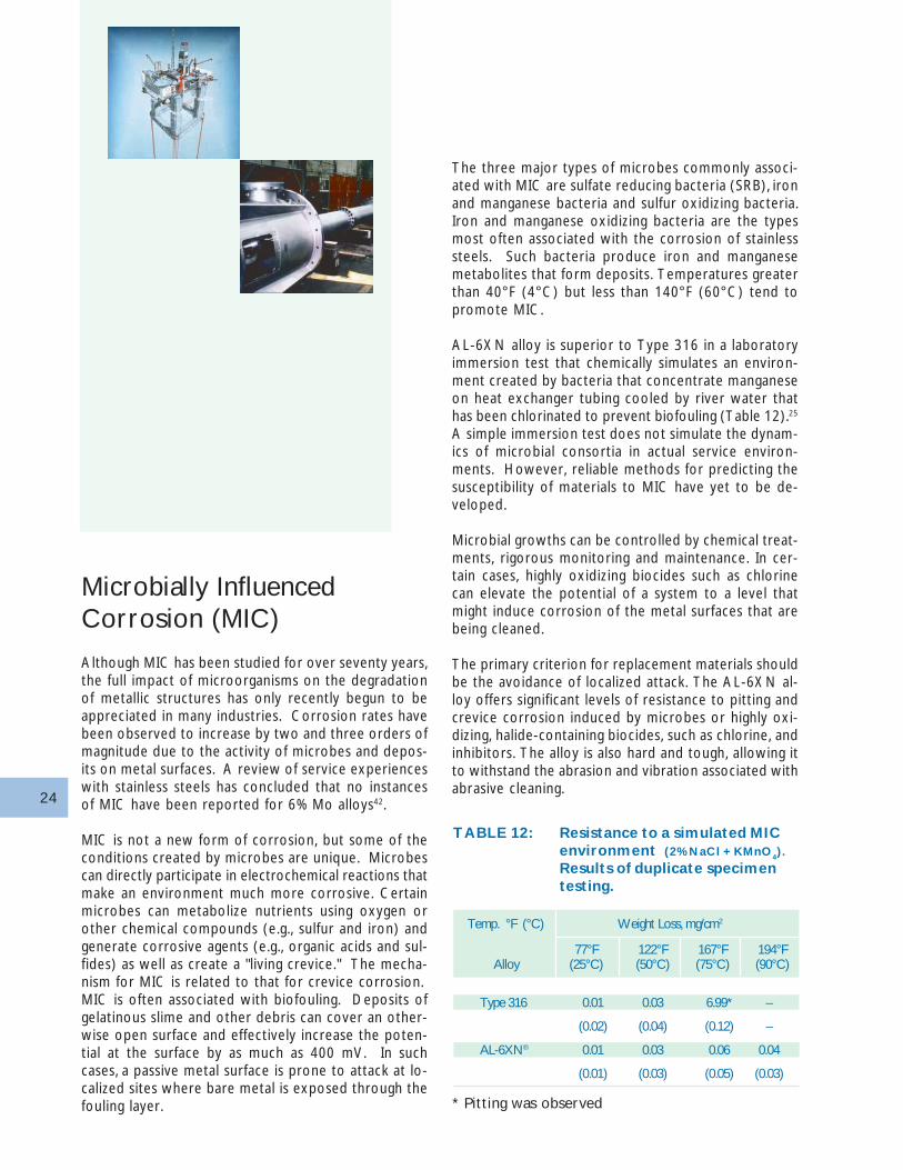
The primary criterion for replacement materials shouldbe the avoidance of localized attack. The AL-6XN al-loy offers significant levels of resistance to pitting andcrevice corrosion induced by microbes or highly oxi-dizing, halide-containing biocides, such as chlorine, andinhibitors. The alloy is also hard and tough, allowing itto withstand the abrasion and vibration associated withabrasive cleaning.
25
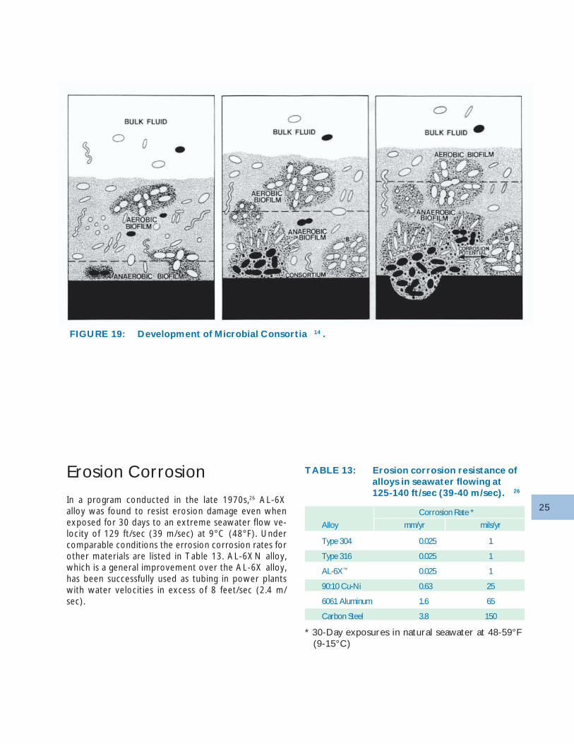
FIGURE 19: Development of Microbial Consortia 14 .
TABLE 13: Erosion corrosion resistance ofalloys in seawater flowing at125-140 ft/sec (39-40 m/sec). 26
Erosion Corrosion
In a program conducted in the late 1970s,26 AL-6Xalloy was found to resist erosion damage even whenexposed for 30 days to an extreme seawater flow ve-locity of 129 ft/sec (39 m/sec) at 9°C (48°F). Undercomparable conditions the errosion corrosion rates forother materials are listed in Table 13. AL-6XN alloy,which is a general improvement over the AL-6X alloy,has been successfully used as tubing in power plantswith water velocities in excess of 8 feet/sec (2.4 m/sec).
Corrosion Rate *
Alloy mm/yr mils/yr
Type 304 0.025 1
Type 316 0.025 1
AL-6X™ 0.025 1
90:10 Cu-Ni 0.63 25
6061 Aluminum 1.6 65
Carbon Steel 3.8 150
* 30-Day exposures in natural seawater at 48-59°F(9-15°C)
26
PhysicalPropertiesThe physical properties of the AL-6XN alloy are simi-lar to those of other austenitic stainless steels (Table14). The elastic modulus values of AL-6XN alloy arelower than those for Type 316L and Alloy 625. How-ever, these modulus values are high in comparison toother non-ferrous alloys, such as titanium (15 x 106
psi). Consequently, AL-6XN alloy, unlike titanium, canreplace copper alloy condenser tubing without theneed for modifying the condenser design or addingadditional support plates to avoid vibration damage.The thermal conductivity and coefficient of expansionvalues are lower than those for Type 316L but arehigher than Alloy 625. Although the thermal conduc-tivity of AL-6XN alloy is significantly lower than thatfor copper-base alloys, studies have shown that thethermal conductivity of the tube wall accounts for onlyabout 2% of the total heat transfer resistance in steamcondenser service46.
AL-6XN alloy has a stable face-centered cubic crystalstructure similar to other austenitic stainless alloys. TheAL-6XN alloy is non-magnetic. Its magnetic permeabil-ity remains low even after severe cold forming. Typi-cal physical properties of AL-6XN alloy are presentedin Tables 16, 17 and 18.
PHYSICAL PROPERTIES
Mechanical Properties
Annealed Condition
Fatigue properties
Welded Condition
Heat Treatment
Open-Air Annealing
Catastrophic Oxidation
Bright Annealing
Forming
Hot Forming
Warm Forming
Cold Forming
Tube Forming
Machinability
Cutting
TABLE 14: Comparison of physical properties.
Thermal Conductivity Expansion CoefficientAlloy Elastic Modulus at 212°F (100°C) from 77 to 212°F
psi x 106 GPa Btu/hr•ft•°F W/mk 10-6/°F 10-6/°C
Type 316 29.0 200 9.2 16.0 8.5 15.3
90:10 Cu-Ni 18.0 124 26.0 45.0 9.3 16.8
70:30 Cu-Ni 22.0 152 17.0 29.4 8.5 15.4
Titanium 15.0 103 9.5 16.4 5.0 9.1
Alloy 904L 28.3 195 7.6 13.2 8.3 15.0
AL-6XN® 28.3 195 7.5 13.0 7.9 14.2
Alloy 625 29.7 205 6.2 10.7 7.1 12.8
27
TABLE 15: Physical properties of AL-6XN ®
Alloy at room temperature.
Property Value Units
Density 0.291 lb/in3
8.06 g/cm3
Modulus of elasticity 28.3 x 10⁶ psi195 GPa
Melting Range 2410 to 2550 °F1320 to 1400 °C
Thermal Conductivity68 to 212°F 6.8 Btu/hr•ft•°F20 to 100°C 11.8 W/mkCoefficient of Expansion68 to 212°F 8.5 10-6/°F20 to 100°C 15.3 10-6/°CSpecific Heat Capacity 0.11 Btu/lb•°F
500 J/kg•KElectrical Resistivity 535 Ohm•circ mil/ft
0.89 µΩ cmMagnetic PermeabilityFully annealed 0.5” plate 1.0028 Oersted65% cold-worked plate 1.0028 (µ at 200H)Scaling Temperature 1885 °F
1030 °C
TABLE 17: Effect of Temperature onAL-6XN® Alloy PhysicalProperties
Temp Temp Specific Specific Thermal°C °F Heat Heat Diffusivity
(BTU/ (J/kg·K) (cm2/s)lb·°F)
21 70 0.113 474 0.0305
100 212 0.118 492 0.0331
200 392 0.123 514 0.0364
300 572 0.128 536 0.0395
400 752 0.133 557 0.0423
500 932 0.138 578 0.0447
600 1112 0.146 610 0.0473
700 1292 0.149 622 0.0494
800 1472 0.151 633 0.0512
900 1652 0.153 642 0.0530
1000 1832 0.156 651 0.0542
1100 2012 0.158 660 0.0554
1200 2192 0.160 668 0.0563
1300 2372 0.162 676 0.0573
TABLE 16: Effect of Temperature on AL-6XN ® Alloy Physical Properties
Temp °F Thermal Thermal Temp °C Thermal ThermalExpansion* Conductivity Expansion* Conductivity
(10-6/°F) (BTU/hr·ft·°F) (10-6/°C) (W/m·K)
200 7.84 7.50 93 14.11 12.98
400 8.36 8.76 204 15.05 15.16
600 8.59 10.03 316 15.46 17.36
800 8.75 11.23 427 15.75 19.43
1000 8.96 12.55 538 16.13 21.72
1200 9.24 13.91 649 16.63 24.07
1400 9.45 14.76 760 17.01 25.55
1600 9.61 15.64 871 17.30 27.07
1800 9.77 16.32 982 17.59 28.25
2000 9.93 17.26 1093 17.87 29.87
2200 10.12 17.52 1204 18.22 30.32
2400 10.35 18.10 1316 18.63 31.33
*Mean coefficient from 70°F (21°C) to temperature indicated
28TABLE 19: Typical tensile properties for
austenitic stainless alloy sheet.
Properties at Type Alloy AL-6XN®
Room Temperature 316 904L Alloy
Yield Srength, ksi (MPa) 45 42 53(0.2% Offset) (310) (290) (365)Ultimate Tensile 88 86 108Strength ksi (MPa) (607) (593) (744)% Elongation in 2” (51 mm) 57 43 47Hardness Rockwell B 81 79 88(Rockwell 30T) (65) (63) (73)
MechanicalPropertiesAnnealed Condition
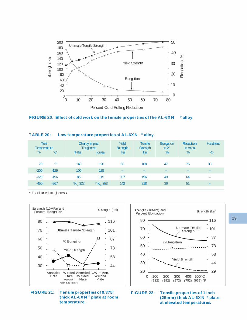
In comparison to more conventional austenitic stain-less steels, the AL-6XN alloy is much stronger withcomparable ductility. Table 19 shows typical trans-verse tensile properties at room temperature forAL-6XN sheet 0.026 to 0.139 inches (0.66 to 3.53 mm)thick in comparison to other austenitic stainless flatrolled products. The hardness of the alloy is relativelyhigh (typically 88 RB) and the alloy work hardens in amanner similar to other stable austenitic stainless steels(Figure 20).
The AL-6XN alloy also demonstrates excellent tough-ness even at subzero temperatures. Table 20 presentsvalues for standard size Charpy V-notch specimens thatwere held at very low temperatures for one hour priorto impact testing.
The strength of the AL-6XN plate is maintained at el-evated temperatures (Figure 22). The ASME maxi-mum allowable values of tensile stress for AL-6XN alloyand other austenitic alloys in the form of sheet or stripthat is less than 3/16 inches (4.8 mm) thick appear inFigure 23.
TABLE 18: AL-6XN ® alloy (UNS N08367) Modulus of Elasticity in Tension
Temp Temp Modulus Modulus°F °C 106 psi MPa
75 24 28.3 195
200 93 27.4 189
400 204 26.1 180
600 316 24.8 171
800 427 23.4 161
1000 538 22.1 152
MECHANICAL PROPERTIES
Annealed Condition
Fatigue Properties
Welded Condition
29
FIGURE 22: Tensile properties of 1 inch(25mm) thick AL-6XN ® plateat elevated temperatures.
FIGURE 21: Tensile properties of 0.375”thick AL-6XN ® plate at roomtemperature.
FIGURE 20: Effect of cold work on the tensile properties of the AL-6XN ® alloy.
807060504030201000
20406080
100120140160180200
Percent Cold Rolling Reduction
Stre
ngth
, ksi
Elongation
Ultimate Tensile Strength
Yield Strength
50
40
30
20
10
0
Elon
gatio
n, %
TABLE 20: Low temperature properties of AL-6XN ® alloy.
Test Charpy Impact Yield Tensile Elongation Reduction HardnessTemperature Toughness Strength Strength in 2” in Area
°F °C ft-lbs joules ksi ksi % % Rb
70 21 140 190 53 108 47 75 88
-200 -129 100 135 – – – – –
-320 -196 85 115 107 196 49 64 –
-450 -267 *K1c 322 * K1c 353 142 218 36 51 –
* fracture toughness
Strength (ksi)
116
101
87
73
58
44
80
70
60
50
40
30
AnnealedPlate
WeldedPlate
(GMAWwith 625 Filler)
AnnealedWelded
Plate
CW + Ann.Welded
Plate
Strength (10MPa) andPercent Elongation
Ultimate Tensile Strength
% Elongation
Yield Strength
116
101
87
73
58
44
29
80
70
60
50
40
30
20
Ultimate TensileStrength
% Elongation
Yield Strength
0 100 200 300 400 500°C(212) (392) (572) (752) (932) °F
Strength (ksi)Strength (10MPa) andPercent Elongation
30
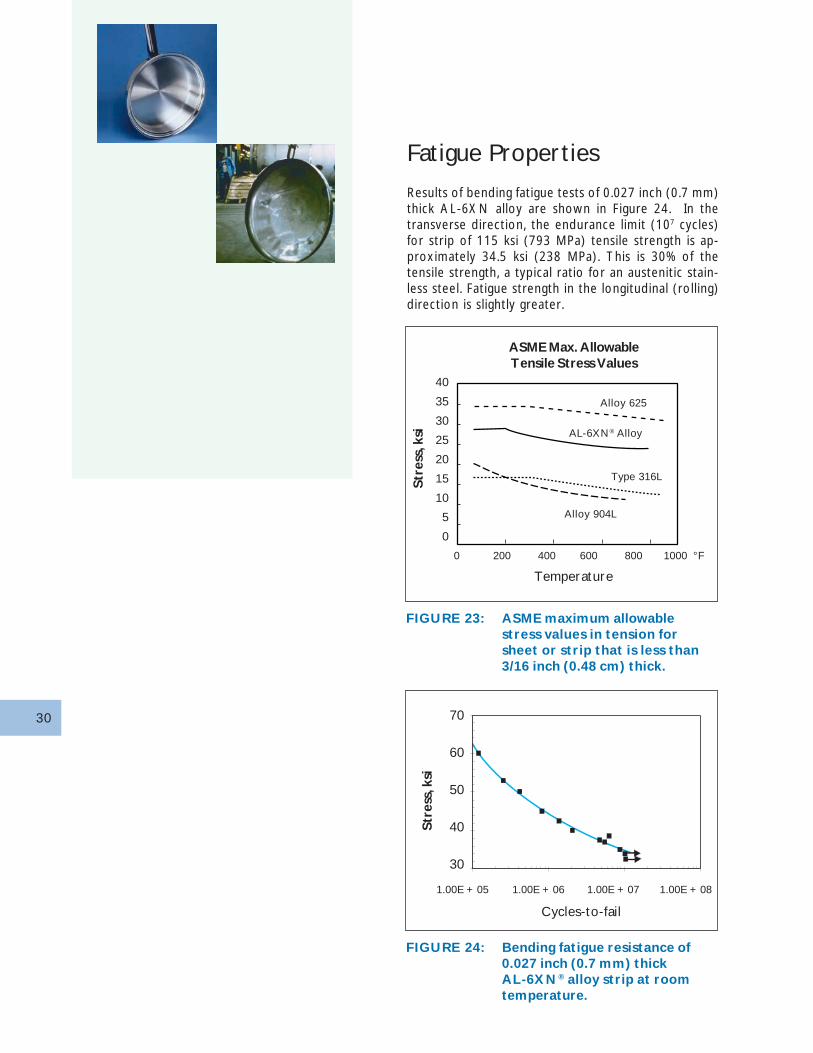
FIGURE 23: ASME maximum allowablestress values in tension forsheet or strip that is less than3/16 inch (0.48 cm) thick.
FIGURE 24: Bending fatigue resistance of0.027 inch (0.7 mm) thickAL-6XN® alloy strip at roomtemperature.
Fatigue Properties
Results of bending fatigue tests of 0.027 inch (0.7 mm)thick AL-6XN alloy are shown in Figure 24. In thetransverse direction, the endurance limit (107 cycles)for strip of 115 ksi (793 MPa) tensile strength is ap-proximately 34.5 ksi (238 MPa). This is 30% of thetensile strength, a typical ratio for an austenitic stain-less steel. Fatigue strength in the longitudinal (rolling)direction is slightly greater.
40
35
30
25
20
15
10
5
0
Alloy 625
0 200 400 600 800 1000 °F
AL-6XN® Alloy
Type 316L
Alloy 904L
Temperature
Str
ess,
ksi
ASME Max. AllowableTensile Stress Values
Str
ess,
ksi
70
60
50
40
30
1.00E + 05 1.00E + 06 1.00E + 07 1.00E + 08
Cycles-to-fail
31
Welded Condition
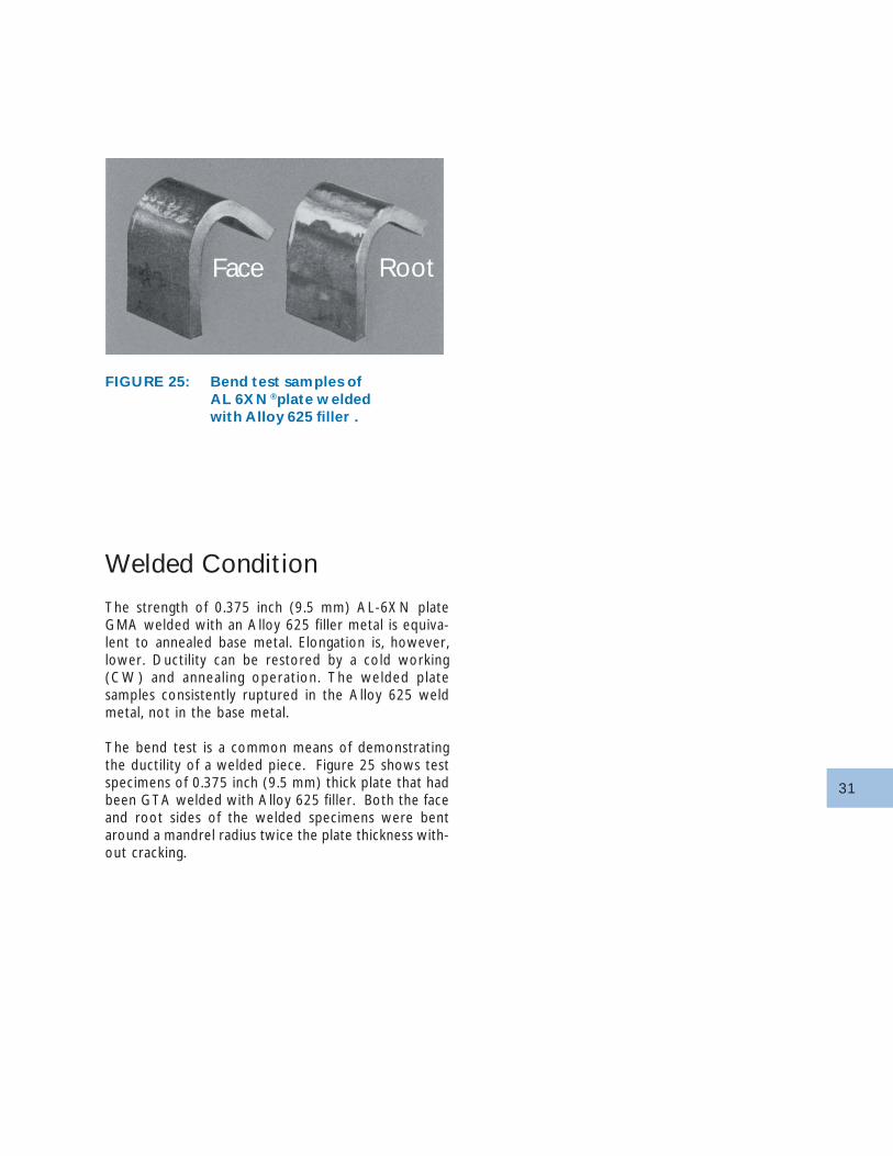
The strength of 0.375 inch (9.5 mm) AL-6XN plateGMA welded with an Alloy 625 filler metal is equiva-lent to annealed base metal. Elongation is, however,lower. Ductility can be restored by a cold working(CW) and annealing operation. The welded platesamples consistently ruptured in the Alloy 625 weldmetal, not in the base metal.
The bend test is a common means of demonstratingthe ductility of a welded piece. Figure 25 shows testspecimens of 0.375 inch (9.5 mm) thick plate that hadbeen GTA welded with Alloy 625 filler. Both the faceand root sides of the welded specimens were bentaround a mandrel radius twice the plate thickness with-out cracking.
FIGURE 25: Bend test samples ofAL 6XN ®plate w eldedwith Alloy 625 filler .
Face Root
32
Heat TreatmentOpen-Air Annealing
AL-6XN products are shipped from the mill in the fullyannealed condition. Flat rolled products are annealedat temperatures above 2025 °F (1110 °C) and are thenrapidly cooled to produce a fully austenitic microstruc-ture. Since the cold formability of AL-6XN alloy isexcellent, subsequent heat treatment is generally notrequ i red to ma in t a i n duc t i l i t y and toughnes s .Hot-formed products generally must be heat treatedabove 2025 °F (1110 °C) followed by a rapid cool todissolve any secondary phases that may have precipi-tated during the process. If the cooling after heattreatment is too slow, the corrosion resistance of theAL-6XN alloy will be markedly decreased. Furnacecooling of AL-6XN alloy should be avoided.
CAUTION: To avoid the risk of incipient melting,AL-6XN alloy should never be heated above 2350 °F(1290 °C).
Note that many furnaces that are used to heat treatstainless steels are not capable of operating above1900°F (1040°C), which is 125°F (70°C) below theminimum suggested annealing temperature for AL-6XNalloy. While laboratory studies31 have demonstratedthat second phases are not precipitated during heattreatments at 1950°F (1065°C) or above, and that thissecond phase precipitation is slow at temperaturesabove 1800°F (980°C), final heat treatment of AL-6XNalloy at temperatures below 2025°F (1110°C) is notpermitted for material to be used in ASME pressurevessel construction.
CAUTION: Do not anneal below 2025°F (1110°C).
The period of time that the AL-6XN alloy must beexposed at a given temperature to be effectively an-nealed depends on several factors including the sizeof the workpiece and the annealing temperature. Thetime of exposure must be at least long enough to in-sure that the desired temperature is achieved every-where through the thickness of the workpiece. Ex-tended periods of thermal exposure are not benefi-cial.
Heat treatment in static air at temperatures above1885°F (1030°C) for extended periods may result ina heavy oxide that will be difficult to remove.
HEAT TREATMENT
Open-Air Annealing
Catastrophic Oxidation
Bright Annealing
33
CAUTION: All oxides must be completely removedbefore the alloy is put into service. See page 39:Descaling, Pickling and Cleaning for details.
Since the annealing temperature for AL-6XN alloy isabove the melting temperature of copper, copper con-tamination cracking during annealing is possible. Toprevent this, contact of material to be annealed withcopper or high-copper alloy clamps, tooling, braze al-loy, etc., should be avoided.
Catastrophic Oxidation
Like other alloys which contain substantial amounts ofmolybdenum, AL-6XN alloy is susceptible to cata-strophic oxidation under certain conditions. At hightemperatures, molybdenum trioxide, which is one ofthe products of oxidation of AL-6XN alloy, is usuallyevaporated from the metal surface. When volatiliza-tion is inhibited and liquid molybdenum trioxide re-mains in contact with the metal surface, deep pittingor rapid loss of metal over the entire exposed surfacecan occur. Such catastrophic oxidation can be pre-vented by bright annealing or by avoiding stagnant airconditions during open-air annealing. The followingprecautions are recommended when open air anneal-ing:
• Avoid excessively tight furnaces, furnace loads whichare tightly packed, or other conditions which inhibitthe evaporation of the molybdenum trioxide.
• Avoid re-annealing of material which is heavily scaled.
• Avoid prolonged anneals, especially in the upper endof the annealing temperature range.
Bright Annealing
Material to be bright annealed must be clean and freeof grease, oil or other contaminants (especially sulfurbearing lubricants). Bright annealing should be per-formed in hydrogen, vacuum, cracked ammonia, or inmixtures of hydrogen and nitrogen or inert gas whichhave dew points of -40°F (-40°C) or less. Material tobe bright annealed should be loaded so as to avoidcontact between adjacent pieces; otherwise, piecesmay be bonded together during annealing. This is mostlikely to occur when stacked pieces are annealed ath igh temperature in gas with an extremely lowdewpoint.
As with open-air annealing, some means of forcedcooling must be provided to prevent the precipitation
of deleterious second phases after exposure at hightemperatures. Cooling through the 1200 to 1900°F(650 to 1040°C) temperature range at a rate similarto that provided by air cooling is normally adequate.For a different heat-treating process, representativetest pieces of AL-6XN alloy should be examined todemonstrate that the anneal and subsequent coolingproduce a product having acceptable microstructureand properties.
Bright annealing, when properly performed, precludesthe formation of scale and chrome-depleted areas onthe surface, and therefore pickling is not required.Catastrophic oxidation will not occur during brightannealing. Bright annealing will not always heal pre-existing surface Cr-depletion, so if prior annealing treat-ments have been performed, it is vital to ensure thatthe material to be bright annealed is free from scaleor pre-existing Cr-depletion. Excessively hot and longvacuum annealing may evaporate Cr from surface, es-pecially if CrO
3 can form. Poor atmospheric control in
vacuum annealing may allow either oxidation or car-burization. Cooling rates following vacuum annealingare often very low, even when "gas quenching" prac-tices are used. These cooling rates may not be ad-equate to prevent sigma precipitation in AL-6XN al-loy.
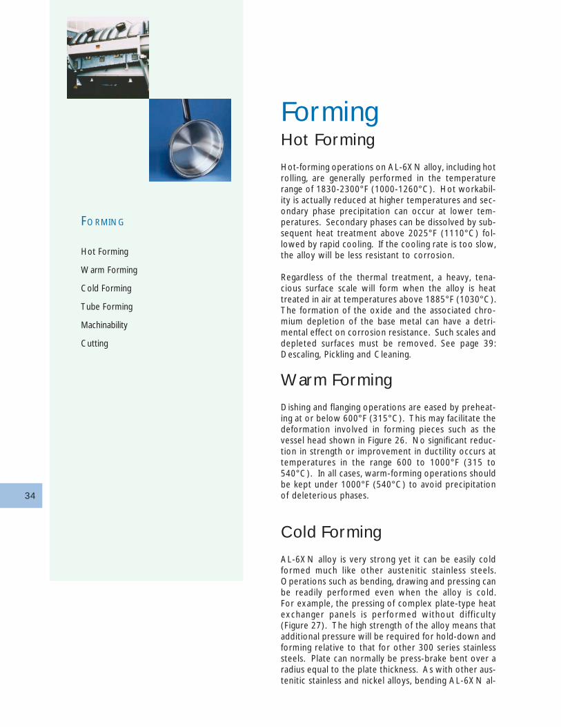
34
FormingHot Forming
Hot-forming operations on AL-6XN alloy, including hotrolling, are generally performed in the temperaturerange of 1830-2300°F (1000-1260°C). Hot workabil-ity is actually reduced at higher temperatures and sec-ondary phase precipitation can occur at lower tem-peratures. Secondary phases can be dissolved by sub-sequent heat treatment above 2025°F (1110°C) fol-lowed by rapid cooling. If the cooling rate is too slow,the alloy will be less resistant to corrosion.
Regardless of the thermal treatment, a heavy, tena-cious surface scale will form when the alloy is heattreated in air at temperatures above 1885°F (1030°C).The formation of the oxide and the associated chro-mium depletion of the base metal can have a detri-mental effect on corrosion resistance. Such scales anddepleted surfaces must be removed. See page 39:Descaling, Pickling and Cleaning.
Warm Forming
Dishing and flanging operations are eased by preheat-ing at or below 600°F (315°C). This may facilitate thedeformation involved in forming pieces such as thevessel head shown in Figure 26. No significant reduc-tion in strength or improvement in ductility occurs attemperatures in the range 600 to 1000°F (315 to540°C). In all cases, warm-forming operations shouldbe kept under 1000°F (540°C) to avoid precipitationof deleterious phases.
Cold Forming
AL-6XN alloy is very strong yet it can be easily coldformed much like other austenitic stainless steels.Operations such as bending, drawing and pressing canbe readily performed even when the alloy is cold.For example, the pressing of complex plate-type heatexchanger panels is performed without di f f iculty(Figure 27). The high strength of the alloy means thatadditional pressure will be required for hold-down andforming relative to that for other 300 series stainlesssteels. Plate can normally be press-brake bent over aradius equal to the plate thickness. As with other aus-tenitic stainless and nickel alloys, bending AL-6XN al-
FORMING
Hot Forming
Warm Forming
Cold Forming
Tube Forming
Machinability
Cutting
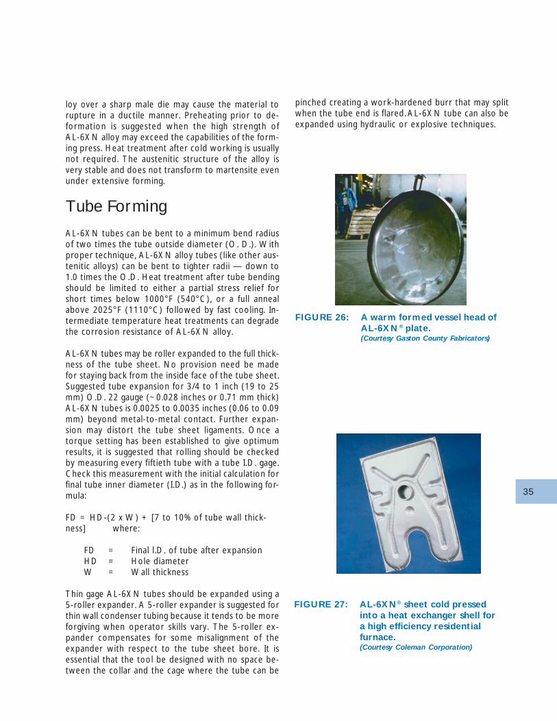
35
loy over a sharp male die may cause the material torupture in a ductile manner. Preheating prior to de-formation is suggested when the high strength ofAL-6XN alloy may exceed the capabilities of the form-ing press. Heat treatment after cold working is usuallynot required. The austenitic structure of the alloy isvery stable and does not transform to martensite evenunder extensive forming.
Tube Forming
AL-6XN tubes can be bent to a minimum bend radiusof two times the tube outside diameter (O. D.). Withproper technique, AL-6XN alloy tubes (like other aus-tenitic alloys) can be bent to tighter radii — down to1.0 times the O.D. Heat treatment after tube bendingshould be limited to either a partial stress relief forshort times below 1000°F (540°C), or a full annealabove 2025°F (1110°C) followed by fast cooling. In-termediate temperature heat treatments can degradethe corrosion resistance of AL-6XN alloy.
AL-6XN tubes may be roller expanded to the full thick-ness of the tube sheet. No provision need be madefor staying back from the inside face of the tube sheet.Suggested tube expansion for 3/4 to 1 inch (19 to 25mm) O.D. 22 gauge (~0.028 inches or 0.71 mm thick)AL-6XN tubes is 0.0025 to 0.0035 inches (0.06 to 0.09mm) beyond metal-to-metal contact. Further expan-sion may distort the tube sheet ligaments. Once atorque setting has been established to give optimumresults, it is suggested that rolling should be checkedby measuring every fiftieth tube with a tube I.D. gage.Check this measurement with the initial calculation forfinal tube inner diameter (I.D.) as in the following for-mula:
FD = HD-(2 x W) + [7 to 10% of tube wall thick-ness] where:
FD = Final l.D. of tube after expansionHD = Hole diameterW = Wall thickness
Thin gage AL-6XN tubes should be expanded using a5-roller expander. A 5-roller expander is suggested forthin wall condenser tubing because it tends to be moreforgiving when operator skills vary. The 5-roller ex-pander compensates for some misalignment of theexpander with respect to the tube sheet bore. It isessential that the tool be designed with no space be-tween the collar and the cage where the tube can be
pinched creating a work-hardened burr that may splitwhen the tube end is flared. AL-6XN tube can also beexpanded using hydraulic or explosive techniques.
FIGURE 26: A warm formed vessel head ofAL-6XN® plate.(Courtesy Gaston County Fabricators)
FIGURE 27: AL-6XN® sheet cold pressedinto a heat exchanger shell fora high efficiency residentialfurnace.(Courtesy Coleman Corporation)
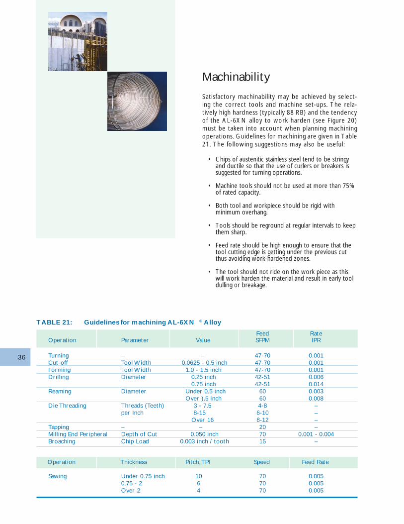
36
Machinability
Satisfactory machinability may be achieved by select-ing the correct tools and machine set-ups. The rela-tively high hardness (typically 88 RB) and the tendencyof the AL-6XN alloy to work harden (see Figure 20)must be taken into account when planning machiningoperations. Guidelines for machining are given in Table21. The following suggestions may also be useful:
• Chips of austenitic stainless steel tend to be stringyand ductile so that the use of curlers or breakers issuggested for turning operations.
• Machine tools should not be used at more than 75%of rated capacity.
• Both tool and workpiece should be rigid withminimum overhang.
• Tools should be reground at regular intervals to keepthem sharp.
• Feed rate should be high enough to ensure that thetool cutting edge is getting under the previous cutthus avoiding work-hardened zones.
• The tool should not ride on the work piece as thiswill work harden the material and result in early tooldulling or breakage.
TABLE 21: Guidelines for machining AL-6XN ® Alloy
Operation Thickness Pitch, TPI Speed Feed Rate
Sawing Under 0.75 inch 10 70 0.0050.75 - 2 6 70 0.005Over 2 4 70 0.005
Feed RateOperation Parameter Value SFPM IPR
Turning – – 47-70 0.001Cut-off Tool Width 0.0625 - 0.5 inch 47-70 0.001Forming Tool Width 1.0 - 1.5 inch 47-70 0.001Drilling Diameter 0.25 inch 42-51 0.006
0.75 inch 42-51 0.014Reaming Diameter Under 0.5 inch 60 0.003
Over ).5 inch 60 0.008Die Threading Threads (Teeth) 3 - 7.5 4-8 –
per Inch 8-15 6-10 – Over 16 8-12 –
Tapping – – 20 –Milling End Peripheral Depth of Cut 0.050 inch 70 0.001 - 0.004Broaching Chip Load 0.003 inch / tooth 15 –
37
• Heavy cuts will require slower speeds and the use ofa lubricant is suggested.
• Lubricants such as sulfur-chlorinated petroleum oilare suggested. Lubricants may be thinned withparaffin oil for finish cuts at higher speeds. All tracesof cutting fluid must be removed prior to welding,annealing, or using in corrosive service.
Cutting
AL-6XN plate may be wet or dry abrasive sawed,sheared, laser cut or plasma-arc cut. Shears rated for3/8 inch (9.5 mm) mild steel are used to cut up to 1/4inch (6.4 mm) thick plate. However, the AL-6XN alloyand other austenitic grades are quite ductile in theannealed condition but work harden more rapidly andrequire more power and time to cut by sawing thando plain carbon steels.
Like other stainless steels and nickel-chromium alloys,the properties of AL-6XN alloy can be degraded bycarbon introduced during oxyacetylene or carbon-arccutting.
CAUTION: AL-6XN alloy must not be cut by oxy-acetylene or carbon-arc procedures.
Plasma-arc cutting is commonly used to cut shapes inAL-6XN plate through 2 inch (51 mm) thickness.
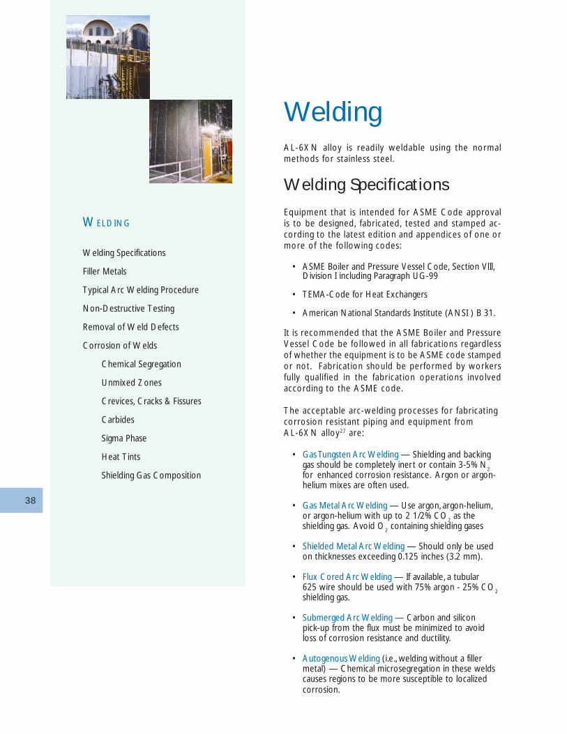
38
WeldingAL-6XN alloy is readily weldable using the normalmethods for stainless steel.
Welding Specifications
Equipment that is intended for ASME Code approvalis to be designed, fabricated, tested and stamped ac-cording to the latest edition and appendices of one ormore of the following codes:
• ASME Boiler and Pressure Vessel Code, Section VlIl,Division I including Paragraph UG-99
• TEMA-Code for Heat Exchangers
• American National Standards Institute (ANSI ) B 31.
It is recommended that the ASME Boiler and PressureVessel Code be followed in all fabrications regardlessof whether the equipment is to be ASME code stampedor not. Fabrication should be performed by workersfully qualified in the fabrication operations involvedaccording to the ASME code.
The acceptable arc-welding processes for fabricatingcorrosion resistant piping and equipment fromAL-6XN alloy27 are:
• Gas Tungsten Arc Welding — Shielding and backinggas should be completely inert or contain 3-5% N
2for enhanced corrosion resistance. Argon or argon-helium mixes are often used.
• Gas Metal Arc Welding — Use argon, argon-helium,or argon-helium with up to 2 1/2% CO
2 as the
shielding gas. Avoid O2 containing shielding gases
• Shielded Metal Arc Welding — Should only be usedon thicknesses exceeding 0.125 inches (3.2 mm).
• Flux Cored Arc Welding — If available, a tubular625 wire should be used with 75% argon - 25% CO
2shielding gas.
• Submerged Arc Welding — Carbon and siliconpick-up from the flux must be minimized to avoidloss of corrosion resistance and ductility.
• Autogenous Welding (i.e., welding without a fillermetal) — Chemical microsegregation in these weldscauses regions to be more susceptible to localizedcorrosion.
WELDING
Welding Specifications
Filler Metals
Typical Arc Welding Procedure
Non-Destructive Testing
Removal of Weld Defects
Corrosion of Welds
Chemical Segregation
Unmixed Zones
Crevices, Cracks & Fissures
Carbides
Sigma Phase
Heat Tints
Shielding Gas Composition
39
Autogenous welding can be used with the followingprecautions:35
• Use of 3 to 5 volume percent nitrogen in theshielding gas, and
• A post-weld anneal above 2150°F (1180°C) followedby rapid cooling and pickling if a protectiveatmosphere was not used during annealing.
• The duration of the anneal must be sufficient tore-homogenize the weld segregation.
• The G48-B crevice test can be used to assess thequality of autogenously welded and annealedAL-6XN alloy.
In many applications, a post-weld anneal and picklemay not be possible such as large vessel fabrication orfield welding of piping systems. In these cases, theexposure conditions must be carefully reviewed to de-termine if autogenous welds are satisfactory. Autog-enous AL-6XN welds are more resistant to corrosionthan similar welds of Types 316L, 317L and 904L.Their corrosion resistance is approximately equivalentto that of alloy 904L base metal and is superior tothat of Type 316L or Type 317L base metal.
CAUTION: Do not use Oxyacetylene Weldingbecause carbon pick-up from the flame lowerscorrosion resistance.
Like other austenitic stainless alloys, AL-6XN alloy issusceptible to copper contamination cracking45. Toprevent this, contact of the weld groove and adjacentsurfaces with copper, high-copper alloy clamps, tool-ing, braze alloy, etc., should be avoided.
Various types of flux have been developed recentlythat substantially increase the penetration of gas tung-sten arc welds made in stainless steels. The flux, whichis applied to the surface of the weld joint in the formof a paste, may increase weld penetration up to 300%without a change in welding parameters. Advantagesare decreased welding time and a lower overall heatinput to the material. These fluxes, such as the com-mercially available FASTIG SS-7™, in conjunction withthe proper filler metal have been shown to providethese advantages when welding AL-6XN alloy with-out affecting the overall corrosion resistance of theweldment.
Filler Metals
AL-6XN products have homogeneous compositions ondelivery. However, when the alloy is melted in weld-
ing, elements such as chromium, nickel and par ticu-l a r ly mo lybdenum are segrega ted in the we ld .Such autogenous welds may be susceptible to prefer-ential attack in severely corrosive environments. Afiller metal composition must compensate for chemi-cal segregation in the weld bead. Consequently, fillermetals containing at least 9% Mo are recommendedfor welding AL-6XN alloy when joining it to otheraustenitic, ferritic and duplex stainless steels and mostnickel-base alloys33. The recommended weld fil lermetal (consumables) comply with the American Weld-ing Society (AWS), American Society of MechanicalEngineers Specification (ASME) and Unified NumberSystem (UNS) specifications cited in Table 18. Othernickel-base, high-molybdenum filler metals may also beacceptable if they meet the criteria described below.Consult with Allegheny Ludlum if there are questionsabout other acceptable filler metals. Fully basic or ba-sic rutile types of consumable coatings are suggested.
AL-6XN alloy has been assigned to P Number 45 inSection IX of the ASME boiler and pressure vesselcode. This group includes other Fe-Ni-Cr-Mo alloyssuch as alloys 20, 800, 825, 904L and G.
The choice of the best filler for AL-6XN alloy dependson the service environment and the fabrication situa-tion. Historically, the filler metal most frequently usedto weld AL-6XN alloy is Alloy 625, which containsabout 9% molybdenum. This level of molybdenum en-richment provides little margin for dilution of the fillerby the base metal. Recent studies 48-49 have identifiedother filler metals, especially Alloy 22, as being supe-r ior . The desired pitt ing corrosion res istance ofweldments of AL-6XN alloy can be achieved by se-lecting filler metals having Pitting Resistance Equiva-lent Number (PRE
N) values at least ten higher than
the base metal regardless of the type of arc weldingprocess. If these filler metals are used, the weldmentwill have pitting and crevice corrosion resistance aboutequal to that of the parent metal. In certain applica-tions such as oxidizing acid chlorides, the chromiumcontent of the filler metal is also impor tant.
Since the melting temperature of the AL-6XN alloy[2410-2550°F (1320-1400°C)] is greater than that ofthe f i l l e r meta l s A l loy 625 [2350-2460°F(1290-1350°C)] and Alloy 276 [2415-2500°F(1320-1370°C)], care must be taken to ensure that the basemetal has been properly melted into the filler metal.
When welding a dissimilar metal such as Type 304 stain-less steel, low alloy steel or carbon steel to AL-6XNalloy, the AWS ERNiCrMo-3 consumables may be used.
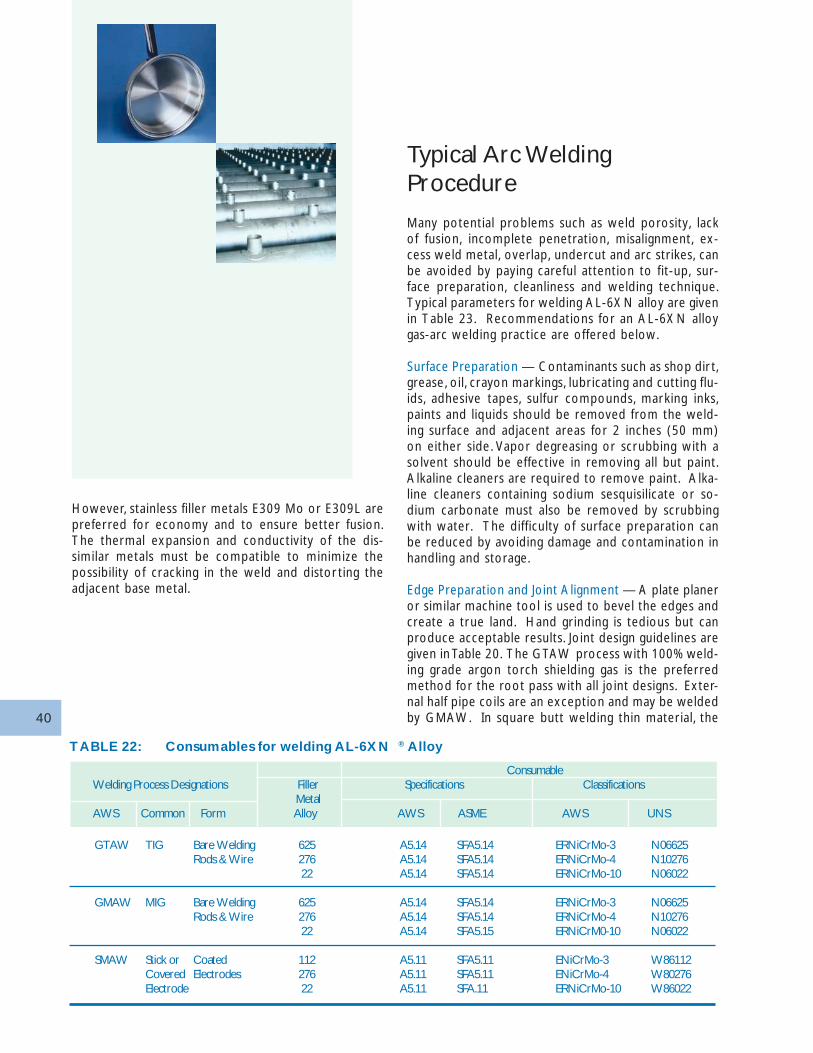
40
TABLE 22: Consumables for welding AL-6XN ® Alloy
GTAW TIG Bare Welding 625 A5.14 SFA5.14 ERNiCrMo-3 N06625Rods & Wire 276 A5.14 SFA5.14 ERNiCrMo-4 N10276
22 A5.14 SFA5.14 ERNiCrMo-10 N06022
GMAW MIG Bare Welding 625 A5.14 SFA5.14 ERNiCrMo-3 N06625Rods & Wire 276 A5.14 SFA5.14 ERNiCrMo-4 N10276
22 A5.14 SFA5.15 ERNiCrM0-10 N06022
SMAW Stick or Coated 112 A5.11 SFA5.11 ENiCrMo-3 W86112Covered Electrodes 276 A5.11 SFA5.11 ENiCrMo-4 W80276Electrode 22 A5.11 SFA.11 ERNiCrMo-10 W86022
ConsumableWelding Process Designations Filler Specifications Classifications
MetalAWS Common Form Alloy AWS ASME AWS UNS
However, stainless filler metals E309 Mo or E309L arepreferred for economy and to ensure better fusion.The thermal expansion and conductivity of the dis-similar metals must be compatible to minimize thepossibility of cracking in the weld and distor ting theadjacent base metal.
Typical Arc WeldingProcedure
Many potential problems such as weld porosity, lackof fusion, incomplete penetration, misalignment, ex-cess weld metal, overlap, undercut and arc strikes, canbe avoided by paying careful attention to fit-up, sur-face preparation, cleanliness and welding technique.Typical parameters for welding AL-6XN alloy are givenin Table 23. Recommendations for an AL-6XN alloygas-arc welding practice are offered below.
Surface Preparation — Contaminants such as shop dir t,grease, oil, crayon markings, lubricating and cutting flu-ids, adhesive tapes, sulfur compounds, marking inks,paints and liquids should be removed from the weld-ing surface and adjacent areas for 2 inches (50 mm)on either side. Vapor degreasing or scrubbing with asolvent should be effective in removing all but paint.Alkaline cleaners are required to remove paint. Alka-line cleaners containing sodium sesquisilicate or so-dium carbonate must also be removed by scrubbingwith water. The difficulty of surface preparation canbe reduced by avoiding damage and contamination inhandling and storage.
Edge Preparation and Joint Alignment — A plate planeror similar machine tool is used to bevel the edges andcreate a true land. Hand grinding is tedious but canproduce acceptable results. Joint design guidelines aregiven in Table 20. The GTAW process with 100% weld-ing grade argon torch shielding gas is the preferredmethod for the root pass with all joint designs. Exter-nal half pipe coils are an exception and may be weldedby GMAW. In square butt welding thin material, the
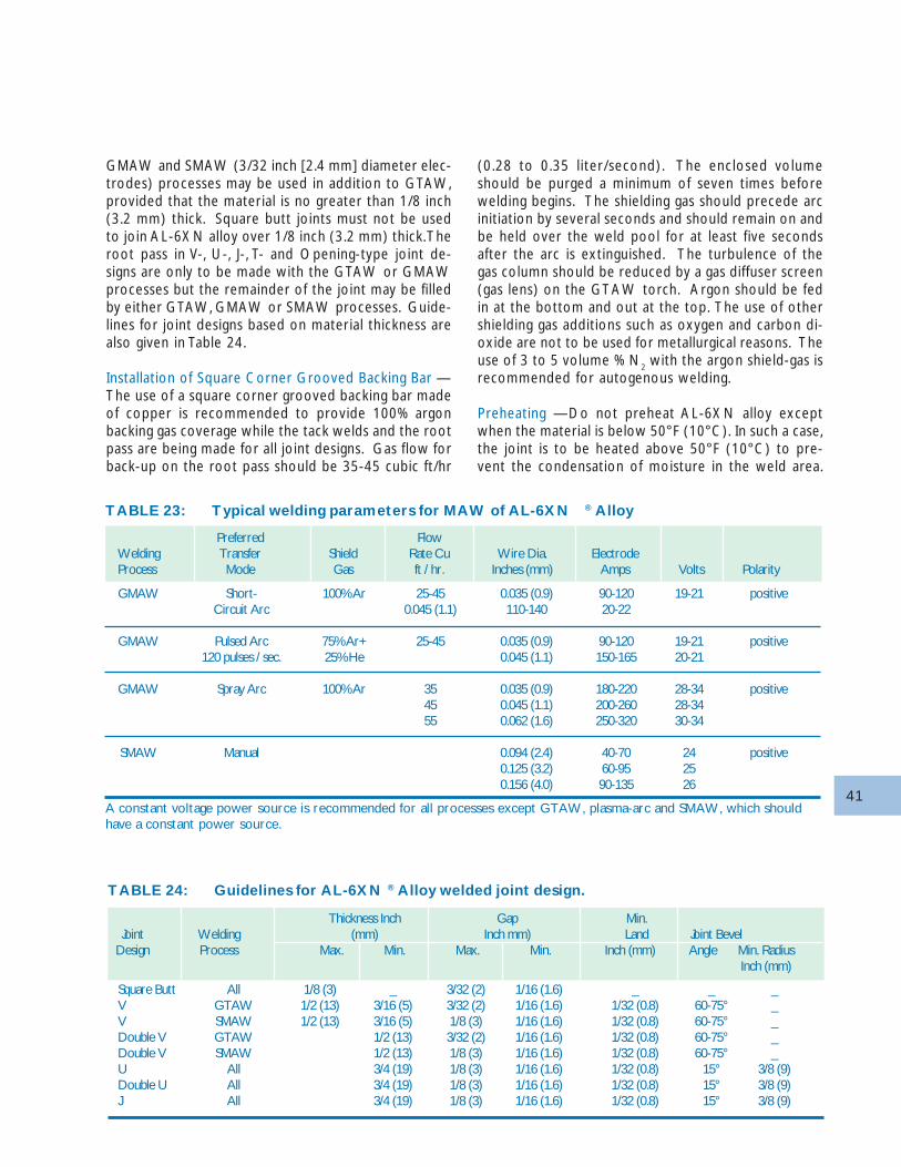
41
GMAW and SMAW (3/32 inch [2.4 mm] diameter elec-trodes) processes may be used in addition to GTAW,provided that the material is no greater than 1/8 inch(3.2 mm) thick. Square butt joints must not be usedto join AL-6XN alloy over 1/8 inch (3.2 mm) thick. Theroot pass in V-, U-, J-, T- and Opening-type joint de-signs are only to be made with the GTAW or GMAWprocesses but the remainder of the joint may be filledby either GTAW, GMAW or SMAW processes. Guide-lines for joint designs based on material thickness arealso given in Table 24.
Installation of Square Corner Grooved Backing Bar —The use of a square corner grooved backing bar madeof copper is recommended to provide 100% argonbacking gas coverage while the tack welds and the rootpass are being made for all joint designs. Gas flow forback-up on the root pass should be 35-45 cubic ft/hr
(0.28 to 0.35 liter/second). The enclosed volumeshould be purged a minimum of seven times beforewelding begins. The shielding gas should precede arcinitiation by several seconds and should remain on andbe held over the weld pool for at least five secondsafter the arc is extinguished. The turbulence of thegas column should be reduced by a gas diffuser screen(gas lens) on the GTAW torch. Argon should be fedin at the bottom and out at the top. The use of othershielding gas additions such as oxygen and carbon di-oxide are not to be used for metallurgical reasons. Theuse of 3 to 5 volume % N
2 with the argon shield-gas is
recommended for autogenous welding.
Preheating —Do not preheat AL-6XN alloy exceptwhen the material is below 50°F (10°C). In such a case,the joint is to be heated above 50°F (10°C) to pre-vent the condensation of moisture in the weld area.
TABLE 23: Typical welding parameters for MAW of AL-6XN ® Alloy
GMAW Short- 100% Ar 25-45 0.035 (0.9) 90-120 19-21 positiveCircuit Arc 0.045 (1.1) 110-140 20-22
GMAW Pulsed Arc 75% Ar+ 25-45 0.035 (0.9) 90-120 19-21 positive120 pulses / sec. 25% He 0.045 (1.1) 150-165 20-21
GMAW Spray Arc 100% Ar 35 0.035 (0.9) 180-220 28-34 positive45 0.045 (1.1) 200-260 28-3455 0.062 (1.6) 250-320 30-34
SMAW Manual 0.094 (2.4) 40-70 24 positive0.125 (3.2) 60-95 250.156 (4.0) 90-135 26
A constant voltage power source is recommended for all processes except GTAW, plasma-arc and SMAW, which shouldhave a constant power source.
Preferred FlowWelding Transfer Shield Rate Cu Wire Dia. ElectrodeProcess Mode Gas ft / hr. Inches (mm) Amps Volts Polarity
TABLE 24: Guidelines for AL-6XN ® Alloy welded joint design.
Square Butt All 1/8 (3) _ 3/32 (2) 1/16 (1.6) _ _ _V GTAW 1/2 (13) 3/16 (5) 3/32 (2) 1/16 (1.6) 1/32 (0.8) 60-75° _V SMAW 1/2 (13) 3/16 (5) 1/8 (3) 1/16 (1.6) 1/32 (0.8) 60-75° _Double V GTAW 1/2 (13) 3/32 (2) 1/16 (1.6) 1/32 (0.8) 60-75° _Double V SMAW 1/2 (13) 1/8 (3) 1/16 (1.6) 1/32 (0.8) 60-75° _U All 3/4 (19) 1/8 (3) 1/16 (1.6) 1/32 (0.8) 15° 3/8 (9)Double U All 3/4 (19) 1/8 (3) 1/16 (1.6) 1/32 (0.8) 15° 3/8 (9)J All 3/4 (19) 1/8 (3) 1/16 (1.6) 1/32 (0.8) 15° 3/8 (9)
Thickness Inch Gap Min.Joint Welding (mm) Inch mm) Land Joint Bevel
Design Process Max. Min. Max. Min. Inch (mm) Angle Min. RadiusInch (mm)
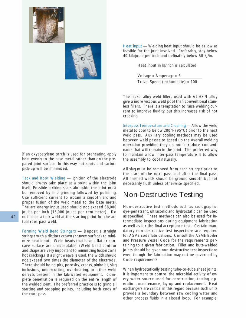
42
Heat Input — Welding heat input should be as low asfeasible for the joint involved. Preferably, stay below40 kilojoule per inch and definately below 50 kJ/in.
Heat input in kJ/inch is calculated:
Voltage x Amperage x 6
Travel Speed (inch/minute) x 100
The nickel alloy weld fillers used with AL-6XN alloygive a more viscous weld pool than conventional stain-less fillers. There is a temptation to raise welding cur-rent to improve fluidity, but this increases risk of hotcracking.
Interpass Temperature and Cleaning — Allow the weldmetal to cool to below 200°F (95°C) prior to the nextweld pass. Auxiliary cooling methods may be usedbetween weld passes to speed up the overall weldingoperation providing they do not introduce contami-nants that will remain in the joint. The preferred wayto maintain a low inter-pass temperature is to allowthe assembly to cool naturally.
All slag must be removed from each stringer prior tothe start of the next pass and after the final pass.All finished welds should be ground smooth but notnecessarily flush unless otherwise specified.
Non-Destructive Testing
Non-destructive test methods such as radiographic,dye-penetrant, ultrasonic and hydrostatic can be usedas specified. These methods can also be used for in-termediate inspections during equipment fabricationas well as for the final acceptance test. Certain man-datory non-destructive test inspections are requiredfor ASME code fabrications. Consult the ASME Boilerand Pressure Vessel Code for the requirements per-taining to a given fabrication. Fillet and butt-weldedjoints should be given non-destructive test inspectionseven though the fabrication may not be governed byCode requirements.
When hydrostatically testing tube-to-tube sheet joints,it is important to control the microbial activity of ev-ery water source used for construction, testing, op-eration, maintenance, lay-up and replacement. Heatexchangers are critical in this regard because such unitsprovide a boundary between raw cooling water andother process fluids in a closed loop. For example,
If an oxyacetylene torch is used for preheating, applyheat evenly to the base metal rather than on the pre-pared joint surface. In this way hot spots and carbonpick-up will be minimized.
Tack and Root Welding — Ignition of the electrodeshould always take place at a point within the jointitself. Possible striking scars alongside the joint mustbe removed by fine grinding followed by polishing.Use sufficient current to obtain a smooth arc andproper fusion of the weld metal to the base metal.The arc energy input used should not exceed 38,000joules per inch (15,000 joules per centimeter). Donot place a tack weld at the starting point for the ac-tual root pass weld.
Forming Weld Bead Stringers — Deposit a straightstringer with a distinct crown (convex surface) to mini-mize heat input. Weld beads that have a flat or con-cave surface are unacceptable. (Weld bead contourand shape are very important to minimizing fusion zonehot cracking.) If a slight weave is used, the width shouldnot exceed two times the diameter of the electrode.There should be no pits, porosity, cracks, pinholes, slaginclusions, undercutting, overheating, or other welddefects present in the fabricated equipment. Com-plete penetration is required on the entire length ofthe welded joint. The preferred practice is to grind allstarting and stopping points, including both ends ofthe root pass.
43
stainless steel and copper alloy heat exchanger tubinghas failed prior to star t-up because of the water leftin the heat exchanger after hydrostatic testing. Mi-crobes in the test water were allowed to breed andgrow, resulting in microbially influenced corrosion. Seepage 22: Corrosion Proper ties — Microbially Influ-enced Corrosion (MIC).
Removal of Weld Defects
All rejectable weld defects should be completely re-moved by grinding. The ground crater should be dye-penetrant inspected to insure that all objectionabledefects have been removed. The area of the repairshould be thoroughly cleaned prior to the weld re-pair. Do not attempt to heal cracks and wash out de-fects by remelting weld beads or by depositing addi-tional weld beads over a defect.
It is extremely important to clean the weld and adja-cent regions after fabricat ion. Refer to page 39:Descaling, Pickling and Cleaning— Postweld Cleaning.
Corrosion ofWeldsChemical Segregation
Microsegregation or coring normally occurs in austen-itic weld metal dendrites. Localized regions within aweld can contain significantly less molybdenum thanadjacent regions. Such molybdenum-depleted regionsare much more susceptible to localized attack, even inmoderately oxidizing solutions. This mode of attack ismost likely to occur when the GTAW process involves:
• no filler metal (i.e., autogenous welds),
• filler metal that has the same composition as the basemetal, or
• high heat input.
The use of a filler metal that is overmatched in molyb-denum is recommended for welding AL-6XN alloy tocompensate for chemical segregation effects.
Unmixed Zones
High heat input welding can leave narrow bands ofbase metal adjacent to the fusion line that has beenmelted but not mixed with the over-matched fillermetal. Such an unmixed zone behaves like an autog-enous weld in a corrosive environment. Controllingthe heat input and avoiding undercutting (i.e., allowingthe final filler metal pass to flow beyond the fusionline) will help to prevent this problem.
Crevices, Cracks & Fissures
Defects such as residual welding flux and microfissurescreate crevices that are particularly susceptible to cor-rosion in chloride-containing environments. Some fluxformulations on coated stick electrodes produce slagsthat readily detach (rutile or titania base) while othersare difficult to remove completely (basic-coated elec-t rodes fo r ou t -o f -pos i t i on we ld ing ) even bygrit-blasting. Small particles of slag that remain on thesurface can act as initiation sites for crevice attack.
Microfissures or their larger counterparts, hot cracks,also provide easy initiation sites for crevice attack whichwill drastically reduce the corrosion resistance of aweldment. Microfissures are caused by thermal con-traction stresses during weld solidification and are aproblem that plagues austenitic stainless steel fabrica-tions. Small-scale microfissures are often invisible tothe naked eye, and their existence can readily explainthe unexpectedly poor pitting performance of one ofa group of weldments made with filler metals of ap-parently similar general composition. The microfissureprovides a crevice which may corrode because stain-less alloys are more susceptible to crevice corrosionthan to pitting. Microfissure crevice corrosion is oftenmistakenly interpreted as self-initiated pitting.
Crevice-corrosion sites can also occur at the begin-ning or end of weld passes, between weld passes, orunder weld spatter areas. Weld spatter is most trouble-some when it is loose or poorly adherent. Corrosionassociated with microfissures in welded AL-6XN alloyunits is best minimized by the use of an over-matchedfiller metal as described in detail on page 33: Weld-ing—Filler Metals.
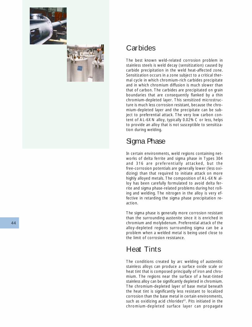
44
Carbides
The best known weld-related corrosion problem instainless steels is weld decay (sensitization) caused bycarbide precipitation in the weld heat-affected zone.Sensitization occurs in a zone subject to a critical ther-mal cycle in which chromium-rich carbides precipitateand in which chromium diffusion is much slower thanthat of carbon. The carbides are precipitated on grainboundaries that are consequently flanked by a thinchromium-depleted layer. This sensitized microstruc-ture is much less corrosion resistant, because the chro-mium-depleted layer and the precipitate can be sub-ject to preferential attack. The very low carbon con-tent of AL-6XN alloy, typically 0.02% C or less, helpsto provide an alloy that is not susceptible to sensitiza-tion during welding.
Sigma Phase
In certain environments, weld regions containing net-works of delta ferrite and sigma phase in Types 304and 316 a re p re fe ren t i a l l y a t t a cked , bu t thefree-corrosion potentials are generally lower (less oxi-dizing) than that required to initiate attack on morehighly alloyed metals. The composition of AL-6XN al-loy has been carefully formulated to avoid delta fer-rite and sigma phase-related problems during hot roll-ing and welding. The nitrogen in the alloy is very ef-fective in retarding the sigma phase precipitation re-action.
The sigma phase is generally more corrosion resistantthan the surrounding austenite since it is enriched inchromium and molybdenum. Preferential attack of thealloy-depleted regions surrounding sigma can be aproblem when a welded metal is being used close tothe limit of corrosion resistance.
Heat Tints
The conditions created by arc welding of austeniticstainless alloys can produce a surface oxide scale orheat tint that is composed principally of iron and chro-mium. The regions near the surface of a heat-tintedstainless alloy can be significantly depleted in chromium.The chromium-depleted layer of base metal beneaththe heat tint is significantly less resistant to localizedcorrosion than the base metal in certain environments,such as oxidizing acid chlorides41. Pits initiated in thechromium-depleted sur face layer can propagate
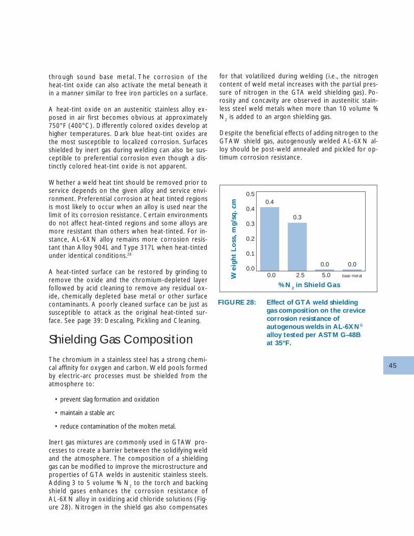
45
through sound base metal . The corrosion of theheat-tint oxide can also activate the metal beneath itin a manner similar to free iron particles on a surface.
A heat-tint oxide on an austenitic stainless alloy ex-posed in air first becomes obvious at approximately750°F (400°C). Differently colored oxides develop athigher temperatures. Dark blue heat-tint oxides arethe most susceptible to localized corrosion. Surfacesshielded by inert gas during welding can also be sus-ceptible to preferential corrosion even though a dis-tinctly colored heat-tint oxide is not apparent.
Whether a weld heat tint should be removed prior toservice depends on the given alloy and service envi-ronment. Preferential corrosion at heat tinted regionsis most likely to occur when an alloy is used near thelimit of its corrosion resistance. Certain environmentsdo not affect heat-tinted regions and some alloys aremore resistant than others when heat-tinted. For in-stance, AL-6XN alloy remains more corrosion resis-tant than Alloy 904L and Type 317L when heat-tintedunder identical conditions.28
A heat-tinted surface can be restored by grinding toremove the oxide and the chromium-depleted layerfollowed by acid cleaning to remove any residual ox-ide, chemically depleted base metal or other surfacecontaminants. A poorly cleaned surface can be just assusceptible to attack as the original heat-tinted sur-face. See page 39: Descaling, Pickling and Cleaning.
Shielding Gas Composition
The chromium in a stainless steel has a strong chemi-cal affinity for oxygen and carbon. Weld pools formedby electric-arc processes must be shielded from theatmosphere to:
• prevent slag formation and oxidation
• maintain a stable arc
• reduce contamination of the molten metal.
Iner t gas mixtures are commonly used in GTAW pro-cesses to create a barrier between the solidifying weldand the atmosphere. The composition of a shieldinggas can be modified to improve the microstructure andproperties of GTA welds in austenitic stainless steels.Adding 3 to 5 volume % N
2 to the torch and backing
shield gases enhances the corrosion resistance ofAL-6XN alloy in oxidizing acid chloride solutions (Fig-ure 28). Nitrogen in the shield gas also compensates
for that volatilized during welding (i.e., the nitrogencontent of weld metal increases with the par tial pres-sure of nitrogen in the GTA weld shielding gas). Po-rosity and concavity are observed in austenitic stain-less steel weld metals when more than 10 volume %N
2 is added to an argon shielding gas.
Despite the beneficial effects of adding nitrogen to theGTAW shield gas, autogenously welded AL-6XN al-loy should be post-weld annealed and pickled for op-timum corrosion resistance.
FIGURE 28: Effect of GTA weld shieldinggas composition on the crevicecorrosion resistance ofautogenous welds in AL-6XN®
alloy tested per ASTM G-48Bat 35°F.
We
igh
t L
oss
, mg/
sq. c
m
% N2 in Shield Gas
0.4
0.3
0.0 0.0
0.0 2.5 5.0 base metal
0.5
0.4
0.3
0.2
0.1
0.0
46
Descaling, Picklingand CleaningAfter operations such as heat treating, forging, or weld-ing, it is necessary to remove tarnish or discolorationor oxide scale and the associated chromium-depletedlayers. Descaling, pickling and cleaning can be laborintensive operations, but are crucial to optimizing theperformance of the AL-6XN alloy in service. Removalis usually accomplished by a two-step process ofdescaling and pickling.
Descaling
AL-6XN alloy can be descaled by either mechanicalor chemical cleaning methods. The more commonmechanical methods include blasting, grinding, machin-ing, and brushing. Blasting involves either steel shotblasting or grit blasting with steel, sand or alumina grits.Under certain circumstances, blasting with 75-100 µmsoda-lime glass beads followed by polishing is effec-tive. Grinding or machining have been successfully usedto remove in one operat ion both scale and thechromium-depleted layer from AL-6XN alloy. Chemi-cal methods of descaling are suggested for thin sec-tions of AL-6XN alloy that may be distorted by theforce of blasting.
CAUTION: Do not use carbon steel or low alloystainless (e.g., Type 410) wire brushes or brushes thathave been used on surfaces other than stainless steelto clean AL-6XN alloy. Iron from the wire brush willcontaminate the AL-6XN alloy surface and may ini-tiate pitting when exposed to an aggressive service en-vironment. Wire brushing typically smears, rather thanremoves contamination and has been typically foundto be ineffective in producing a fully-descaled surface.
Mechanical methods of descaling as well as machiningto final shape, should be followed by either pickling orpassivation treatments. The time required to pickle orpassivate depends on several factors including the op-erating conditions and surface roughness. For instance,rough blasted surfaces are relatively slow to pickle orpassivate because the microbubbles and foreign par-ticles that can be retained on a rough surface reducethe wetting action of the acids.
DESCALING, PICKLING
& CLEANING
Descaling
Pickling
Passivation (Acid Cleaning)
Cleaning Embedded Iron & Scale
Post weld Cleaning
47
Highly oxidizing molten caustic solutions are often usedto chemically descale heavy surface oxides. Such caus-tic solutions are used to condition the scale for com-plete removal in a subsequent acid pickling operation.Electrolytic processes for scale conditioning can alsobe successfully used.
Pickling
Descaling alone is not sufficient to fully restore thecorrosion resistance of AL-6XN alloy after annealing.The subscale chromium-depleted layer must also beremoved. Examination of commercially annealed ma-te r i a l ha s demons t r a ted the ex i s tence o f achromium-depleted layer approximately 12µm (0.0005inch) thick at the metal surface just below the scale.This chromium-depleted layer is typically removed bypickling in nitric plus hydrofluoric acids at 130-140°F(54-60°C). The high corrosion resistance of AL-6XNalloy makes it difficult to pickle. Laboratory corrosiontests in 10% nitric plus 3% hydrofluoric acids (ASTMA-262-86 Practice D solution, based upon typical pick-ling solutions for stainless alloys) at 70°C (158°F) forfour hours yielded the corrosion rates shown29:
These results indicate that AL-6XN alloy must be pick-led much more aggressively than standard stainless steelalloys; conversely, they also demonstrate that overpickling of AL-6XN alloy is not a serious possibility.The rate of pickling can be increased by adjusting thetemperature or composition of the pickling acids. In-creasing the temperature, increasing hydrofluoric acidconcentration and decreasing nitric acid concentrationpromote more rapid pickling. The utility of increasedtemperature in accelerating nitric/hydrofluoric acidpickling is limited, however, by the volatilization of thenitric and hydrofluoric acids at elevated temperatures.For AL-6XN alloy, the speed of pickling can be in-creased by using a bath of 4:4 nitric/hydrofluoric acidsolutions rather than the 10:2 typically used for ordi-nary stainless steels. Excessive concentrations of metalions (iron, nickel, chromium, etc.,) in the pickling acidmay inhibit pickling. These nitric/hydrofluoric acid so-lutions used for pickling also suffice to remove freeiron, etc., from the surface if any was embedded dur-ing the descaling process.
Passivation (Acid Cleaning)
Passivation is a frequently misunderstood term that iscommonly used to describe a cleaning treatment in-volving a weak oxidizing acid such as warm 10 to 20%nitric acid. Such a treatment can promote the refor-mation of the passive film but the principal benefit ofsuch a treatment is that it will remove contaminants.The acid cleaning (passivation) treatment will not cor-rode the AL-6XN alloy and is effectively used aftermachining, shipping or handling.
Cleaning Embedded Iron andScale
Small particles of iron and scale may be firmly embed-ded in a stainless surface during fabrication and clean-ing operations. Such embedded particles may not beremoved by the cleaning methods normally used fordissolving grease or cutting compounds. Under cer-tain conditions, the corrosion of such free iron par-ticles may initiate localized attack of the stainless al-loy. For this reason it is necessary to test for and toremove any free iron present on the surface.See Appendix B.
If embedded iron or scale is detected, it can beremoved by applying either:
• 20% nitric acid or a commercial stainless cleaner
• Commercial stainless cleaner containing nitric andhydrofluoric acids suspended in a paste.
In all cases it is imperative that the cleaning agent bethoroughly removed by rinsing with water after thedesired period of exposure.
Corrosion Rate
Alloy Inches Per Month (mm/y)
Type 316L 0.21 (0.44)
AL-6XN® 0.01 (0.02)
Alloy 276 0.03 (0.06)
TABLE 25: Pickling rates in 10% Nitric +3% Hydrofluoric Acids at 70°C.
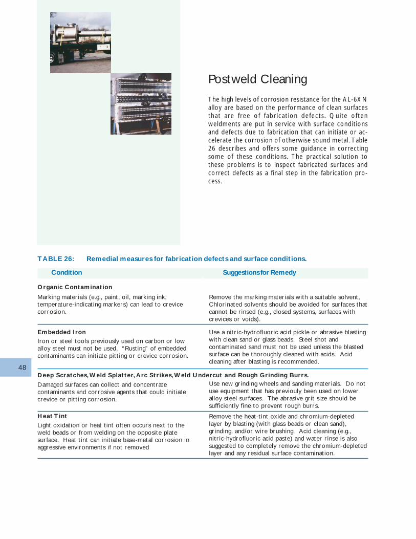
48
Postweld Cleaning
The high levels of corrosion resistance for the AL-6XNalloy are based on the performance of clean surfacesthat are free of fabricat ion defects . Quite oftenweldments are put in service with surface conditionsand defects due to fabrication that can initiate or ac-celerate the corrosion of otherwise sound metal. Table26 describes and offers some guidance in correctingsome of these conditions. The practical solution tothese problems is to inspect fabricated surfaces andcorrect defects as a final step in the fabrication pro-cess.
TABLE 26: Remedial measures for fabrication defects and surface conditions.
Condition Suggestions for Remedy
Marking materials (e.g., paint, oil, marking ink,temperature-indicating markers) can lead to crevicecorrosion.
Remove the marking materials with a suitable solvent,Chlorinated solvents should be avoided for surfaces thatcannot be rinsed (e.g., closed systems, surfaces withcrevices or voids).
Organic Contamination
Iron or steel tools previously used on carbon or lowalloy steel must not be used. “Rusting” of embeddedcontaminants can initiate pitting or crevice corrosion.
Use a nitric-hydrofluoric acid pickle or abrasive blastingwith clean sand or glass beads. Steel shot andcontaminated sand must not be used unless the blastedsurface can be thoroughly cleaned with acids. Acidcleaning after blasting is recommended.
Embedded Iron
Damaged surfaces can collect and concentratecontaminants and corrosive agents that could initiatecrevice or pitting corrosion.
Use new grinding wheels and sanding materials. Do notuse equipment that has previouly been used on loweralloy steel surfaces. The abrasive grit size should besufficiently fine to prevent rough burrs.
Deep Scratches, Weld Splatter, Arc Strikes, Weld Undercut and Rough Grinding Burrs.
Light oxidation or heat tint often occurs next to theweld beads or from welding on the opposite platesurface. Heat tint can initiate base-metal corrosion inaggressive environments if not removed
Remove the heat-tint oxide and chromium-depletedlayer by blasting (with glass beads or clean sand),grinding, and/or wire brushing. Acid cleaning (e.g.,nitric-hydrofluoric acid paste) and water rinse is alsosuggested to completely remove the chromium-depletedlayer and any residual surface contamination.
Heat Tint
49
References1. J. R. Kearns, “The Effect of Nitrogen on the Corrosion of
Austenitic Stainless Steels Containing Molybdenum,” Journal ofMaterials for Energy Systems, Vol. 7, No. 1, p. 17 (1985).
2. H. E. Deverell, C. R. Finn and G. E. Moller, “CorrosionPerformance of 6 Percent Molybdenum Austenitic Alloys AL-6X® and AL-6XN®,” NACE Corrosion 88 Conference, St.Louis, MO, National Association of Corrosion Engineers, PaperNo. 313, 1988.
3. J. R. Kearns and H. E. Deverell, “The Use of Nitrogen toImprove the Corrosion Resistance of FeCrNiMo Alloys for theChemical Process Industry,” Corrosion, Vol. 26, No. 6, p. 18(1987).
4. H. E. Deverell, R. J. Bullock and J. R. Maurer, “The CorrosionResistance of N08367 Stainless Steel for the Pulp and PaperIndustry,” NACE Corrosion 89 Conference, New Orleans, LA,National Association of Corrosion Engineers, Paper No. 56,1989.
5. I. A. Franson and M. J. Johnson, “A New Nitrogen-ModifiedSuperAustenitic Alloy for Seawater Applications,” NACECorrosion 89 Conference, New Orleans, LA, NationalAssociation of Corrosion Engineers, Paper No. 296, 1989.
6. J. R. Maurer, “Application of a Six Percent MolybdenumStainless Alloy for Nuclear Applications,” NACE Corrosion 89Conference, New Orleans, LA, National Association ofCorrosion Engineers, Paper No. 501, 1989.
7. I .A. Franson and J. R. Maurer, “Application of a New HighStrength Fe-Ni-Cr-Mo-N Austenitic Tube Alloy for HighPressure Feedwater Heaters,” Proceedings of EPRI FeedwaterHeater Technology Symposium, Winston-Salem, NC, ElectricPower Research Institute, 1988.
8. I. A. Franson and J. R. Maurer, “An Advanced Fe-Ni-Cr-Mo-NAustenitic Alloy for Utility Heat Exchanger Service,” Proceed-ings of Advances in Material Technology for Fossil PowerPlants, Chicago, IL, ASM International, Paper No. 8706-007,1987.
9. J. R. Maurer, “Improving a Stainless Condenser Tube Alloy witha Small Addition of Nitrogen,” Joint ASME/lEEE PowerGeneration Conference, Milwaukee, Wl, American Society ofMechanical Engineers, Paper No. 85-JPGC-Power-38, 1985.
10. A. Garner, “Materials Selection for Bleached Pulp Washers,”Pulp & Paper Canada, Vol. 82, No. 12, p. 1 (1981).
11. B. Wallén, “Stainless Steel and Titanium Corrosion in PulpBleaching Plants,” 1977 International Symposium Pulp andPaper Industry Corrosion Problems, Houston, TX, NationalAssociation of Corrosion Engineers, p. 43 (1977).
12. L. H. Laliberte, “Corrosion of Stainless Steels in Bleach Plants,”First International Seminar on Pulp and Paper Industry
Corrosion Problems, Houston, TX, National Association ofCorrosion Engineers, p. 51 (1974).
13. J. B. Hill and A. H. Tuthill, “TAPPI Phase II Corrosion TestProgram-Part Il; Weld Metal and Heat-Affected ZoneCorrosion in Bleach Plant Environments,” Fourth InternationalSymposium on Corrosion in Pulp and Paper Industry,Stockholm, Sweden, Swedish Corrosion Institute, p. 142(1983).
14. R. Bandy, Y. C. Lu, R. C. Newman and C. R. Clayton, “Role ofNitrogen in Improving the Resistance to Localized Corrosion inAustenitic Stainless Steels,” Equilibrium Diagrams and LocalizedCorrosion, New Orleans, LA, Electrochemical Society, p. 471(1984).
15. M. A. Streicher, “Analysis of Crevice Corrosion Data from TwoSea Water Exposure Tests on Stainless Alloys,” MaterialsPerformance, Vol. 22, No. 5, p. 37 (1983).
16. A. Garner, “Crevice Corrosion of Stainless Steels in Sea Water:Correlation of Field Data with Laboratory Ferric ChlorideTests,” Corrosion, Vol. 37, No. 3, p. 178 (1981).
17. J. R. Kearns, M. J. Johnson and J. F. Grubb, “AcceleratedCorrosion in Dissimilar Metal Crevices,” NACE Corrosion 86Conference, Houston, TX, National Association of CorrosionEngineers, Paper No. 228, 1986.
18. G. A. Gehring and J. R. Maurer, “Galvanic Corrosion ofSelected Tubesheet/Tube Couples Under Simulated SeawaterCondenser Conditions,” NACE Corrosion 81 Conference,Toronto, Canada, National Association of Corrosion Engineers,Paper No. 202, 1981.
19. G. A. Gehring and R. J. Kyle, “Galvanic Corrosion in SteamSurface Condensers Tubed with Either Stainless Steel orTitanium,” NACE Corrosion 82 Conference, NationalAssociation of Corrosion Engineers, Paper No. 60, 1982.
20. R. Otterberg, “The Influence of Boron Additions on theCorrosion Behavior of Some Austenitic Stainless Steels,”Proceedings of the Ninth International Congress on MetallicCorrosion, Toronto National Research Council, Canada, p. 134(1984).
21. J. R. Kearns, M. J. Johnson and I. A. Franson, “The Corrosion ofStainless Steels and Nickel Alloys in Caustic Solutions,” NACECorrosion 84 Conference, New Orleans, LA, NationalAssociation of Corrosion Engineers, Paper No. 146, 1984.
22. H . R . Copson, “Effect of Composition on Stress CorrosionCracking of Some Alloys Containing Nickel,” Physical Metal-lurgy of Stress Corrosion Fracture, Interscience, New York, p.247 (1959).
23. M. Ueda, H. Abo, T. Sunami, T. Muta and H. Yamamoto, “ANew Austenitic Stainless Steel Having Resistance to StressCorrosion Cracking,” Nippon Steel Technical Report, OverseasNo. 2, January, p. 66 (1973).
24. J. W. Costerson and G. G. Geesey, “The Microbial Ecology ofSurface Colonization and of Consequent Corrosion,”
49
50
Biologically Influenced Corrosion, Gaithersburg, MD, NationalAssociation of Corrosion Engineers, Paper No. 223, 1986.
25. M. A. Streicher, “Development of Pitting Resistant Fe-Cr-Ni-Mo Alloys,” Corrosion, Vol. 30, No. 3, p. 77 (1974).
26. F L. LaQue, “Qualification of Stainless Steel for OTEC HeatExchanger Tubes,” Argonne National Laboratory/OceanThermal Energy Conversion, ANL/OTEC-001, January 1989.
27. “AL-6XN® alloy FABRICATION,” Bulletin 203, June, 2001
28. J. R. Kearns, “Corrosion of Heat Tinted Austenitic StainlessAlloys,” NACE Corrosion 85 Conference, Boston, MA,National Association of Corrosion Engineers, Paper No. 50,1985.
29. J. F. Grubb, “Pickling and Surface Chromium-Depletion ofCorrosion-Resistant Alloys,” Proceedings of InternationalConference on Stainless Steels, Chiba, Japan, June 10-13, 1991,Iron and Steel Institute of Japan.
30. J. F. Grubb and J. R. Maurer, “Correlation of the Microstructureof a 6% Molybdenum Stainless Steel with Performance in aHighly Aggressive Test Medium,” NACE Corrosion 95Conference, Orlando, FL, NACE International, Paper No. 300,1995.
31. J. F. Grubb, “Elevated Temperature Stability of a 6% MoSuperaustenitic Stainless Steel,” NACE Corrosion 96 Confer-ence, Denver, CO, NACE International, Paper No. 426, 1996.
32. J. McConnell, J. Hamer, and I. Franson, “Applications of 6% MoSuperaustenitic Alloy in Severe FGD SystemEnvironments,”Seventh International Seminar: SolvingCorrosion Problems in Air Pollution Control Equipment,Orlando, FL, NACE International, Paper No. 16, 1992.
33. T. G. Gooch and A. C. Elbro, “Welding corrosion resistant highalloy austenitic stainless steel,” International Conference onCorrosion in Natural and Industrial Environments: Problemsand Solutions, Grado, Italy, NACE International, Paper No. 13,1995.
34. J. R. Maurer, “Long-Term Tests of Dissimilar Metal CreviceCorrosion in Filtered Seawater,” Materials Performance, Vol.33, No. 4, p. 51 (1994).
35. J. F. Grubb, “Corrosion Resistance of Welds in AL-6XN®
Alloy,” Eighth Annual North American Welding Conference,Columbus, OH, 1992.
36. J. R. Maurer and J. R. Kearns, “South Carolina power plantupgrades to face highly corrosive environment,” Nickel, Vol. 8,No. 3, p. 7 (1993).
37. J. S. Perrin, D. B. Patten and T. S. Lubnow, “Service WaterSystem Corrosion Test Program for Salem Units 1 and 2,”EPRI Service Water System Reliability Improvement Seminar,Charlotte, NC, 1995
38. NiDI Case Study No. 15001, “Nuclear Service Water Piping,”Nickel Development Institute, 1994.
39. R. S. Tombaugh and J. R. Maurer, “Retubing and BundleReplacement for Life Extension of Nuclear Service WaterSystem Heat Exchangers,” 1991 International Joint PowerGeneration Conference, ASME, San Diego, CA, 1991.
40. R. M. Kain, “Seawater Testing to Assess the Crevice CorrosionResistance of Stainless Steels and Related Alloys,” 12thInternational Corrosion Congress, Houston, TX, NACEInternational, p. 1889, 1993.
41. J. R. Kearns and G. E. Moller, “Reducing Heat Tint Effects onthe Corrosion Resistance of Austenitic Stainless Alloys,”Materials Performance, Vol. 33, No. 5, p. 57 (1994).
42. C. W. Kovach, “A Review of Microbiological Corrosion in ‘HighPerformance Stainless Steels’,” 1995 International Joint PowerGeneration Conference, ASME, Minneapolis, MN, 1995.
43. A H. Tuthill and A. Garner, “Field Test Results for 6% MoStainless and Ni Base Alloy Pipes in the Chlorination Stage of aPulp Mill Bleach Plant,” NACE Corrosion 92 Conference,Nashville, TN, NACE International, Paper No. 319, 1992.
44. P. O. Gartland, U. Steinsmo, J. M. Drugli, and P. Solheim,“Highly Alloyed Stainless Steels for Chlorinated SeawaterApplications - A Summary of Test Results for Eleven Austeniticand Duplex Materials,” NACE Corrosion 93 Conference,New Orleans, LA, NACE International, Paper No. 646, 1993.
45. E. F. Nippes and D. J. Ball, “Copper-Contamination Cracking:Cracking Mechanisms and Crack Inhibitors,” Welding J, Res.Sup. Vol. 61, No. 3, March 1982, 75s-81s.
46. E. L. Lustenader and F. W. Staub, “Development Contributionto Compact Condenser Design,” INCO Power Conference1964, Wrightsville Beach, N.C.
47 J. F. Grubb, J. D. Fritz, B. W. Parks, Jr. and R.E. Polinski, “A 6%Mo Stainless Steel for Flue Gas Desulfurization,” NACECorrosion 2000 Conference, Houston, Texas, NACEInternation, Paper 00583, 2000.
48. K.-K. Baek, H.-J. Sung, C.-S. Im, I.-P. Hong, and D.-K. Kim,"Resistance of High-Alloyed Stainless Steels Welds for FGDPlants in Korea", NACE Corrosion'98, Paper No. 474, NACEInternational: Houston, TX 1998.
49. S. W. Banovik, J. N. DuPont, and A. R. Marder, "FusionWelding of Super Austenitic Stainless Steels" Proceedings fromJoining of Advanced and Specialty Materials, 9-11 October2000, ASM International, 2000.
50. S.C. Dexter and J. P. LaFontaine, “Effect of Natural MarineBiofilms on Galvanic Corrosion Predicted UsingPotentiodynamic Polarization Curves,” NACE Corrosion 98Conference, San Diago, CA, NACE International, Paper No.288, 1998
51. J. D. Fritz, B. W. Parks, J. F. Grubb, and C. P. Stinner, “The Useof Electrochemical Critical Pitting Temperature Measurementsfor Evaluating Stainless Steels,” Stainless Steel World Confer-ence & Expo 2001, 13-15 November 2001, KCI Publishing B.V.Zutphen, The Netherlands.
AL-6XN® is a registered trademark of ATI Properties, Inc.
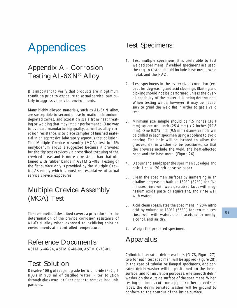
51
Appendices
Appendix A - CorrosionTesting AL-6XN® Alloy
It is important to verify that products are in optimumcondition prior to exposure to actual service, particu-larly in aggressive service environments.
Many highly alloyed materials, such as AL-6XN alloy,are susceptible to second phase formation, chromium-depleted zones, and oxidation scale from heat treat-ing or welding that may impair performance. One wayto evaluate manufacturing quality, as well as alloy cor-rosion resistance, is to place samples of finished mate-rial in an aggressive laboratory aqueous test solution.The Multiple Crevice Assembly (MCA) test for 6%molybdenum alloys is suggested because it providesfor the tightest crevices via prescribed torquing of thecreviced areas and is more consistent than that ob-tained with rubber bands in ASTM G-48B. Testing ofthe flat surface only is provided by the Multiple Crev-ice Assembly which is most representative of actualservice crevice exposures.
Multiple Crevice Assembly(MCA) Test
The test method described covers a procedure for thedetermination of the crevice corrosion resistance ofAL-6XN alloy when exposed to oxidizing chlorideenvironments at a controlled temperature.
Reference DocumentsASTM G-46-94, ASTM G-48-00, ASTM G-78-01.
Test SolutionDissolve 100 g of reagent grade ferric chloride (FeCI
3·6
H2O) in 900 ml of disti l led water. Fi lter solution
through glass wool or filter paper to remove insolubleparticles.
Test Specimens:
1. Test multiple specimens. It is preferable to testwelded specimens. If welded specimens are used,the region tested should include base metal, weldmetal, and the HAZ.
2. Test specimens in the as-received condition (ex-cept for degreasing and acid cleaning). Blasting andpickling should not be performed unless the over-all capability of the material is being determined.When testing welds, however, it may be neces-sary to grind the weld flat in order to get a validtest.
3. Minimum size sample should be 1.5 inches (38.1mm) square or 1 inch (25.4 mm) x 2 inches (50.8mm). One 0.375 inch (9.5 mm) diameter hole willbe drilled in each specimen using a coolant to avoidheating. The hole will be located to allow thegrooved delrin washer to be positioned so thatthe crevices include the weld, the heat-affectedzone and the base metal (Figure 26).
4. Deburr and sandpaper the specimen cut edges andhole. Use a 120 grit abrasive paper.
5. Clean the specimen surfaces by immersing in analkaline degreasing bath at 180°F (82°C) for fiveminutes, rinse with water, scrub surfaces with mag-nesium oxide paste or equivalent, and rinse wellwith water.
6. Acid clean (passivate) the specimens in 20% nitricacid by volume at 130°F (55°C) for ten minutes,rinse well with water, dip in acetone or methylalcohol, and air dry.
7. Weigh the prepared specimen.
Apparatus
Cylindrical serrated delrin washers (G-78, Figure 27),two for each test specimen, will be applied (Figure 28).In the case of tubular or flanged specimens, one ser-rated delrin washer will be positioned on the insidesurface, and for insulation purposes, one smooth delrinwasher on the outside surface of the specimens. Whentesting specimens cut from a pipe or other curved sur-faces, the delrin serrated washer will be ground toconform to the contour of the inside surface.
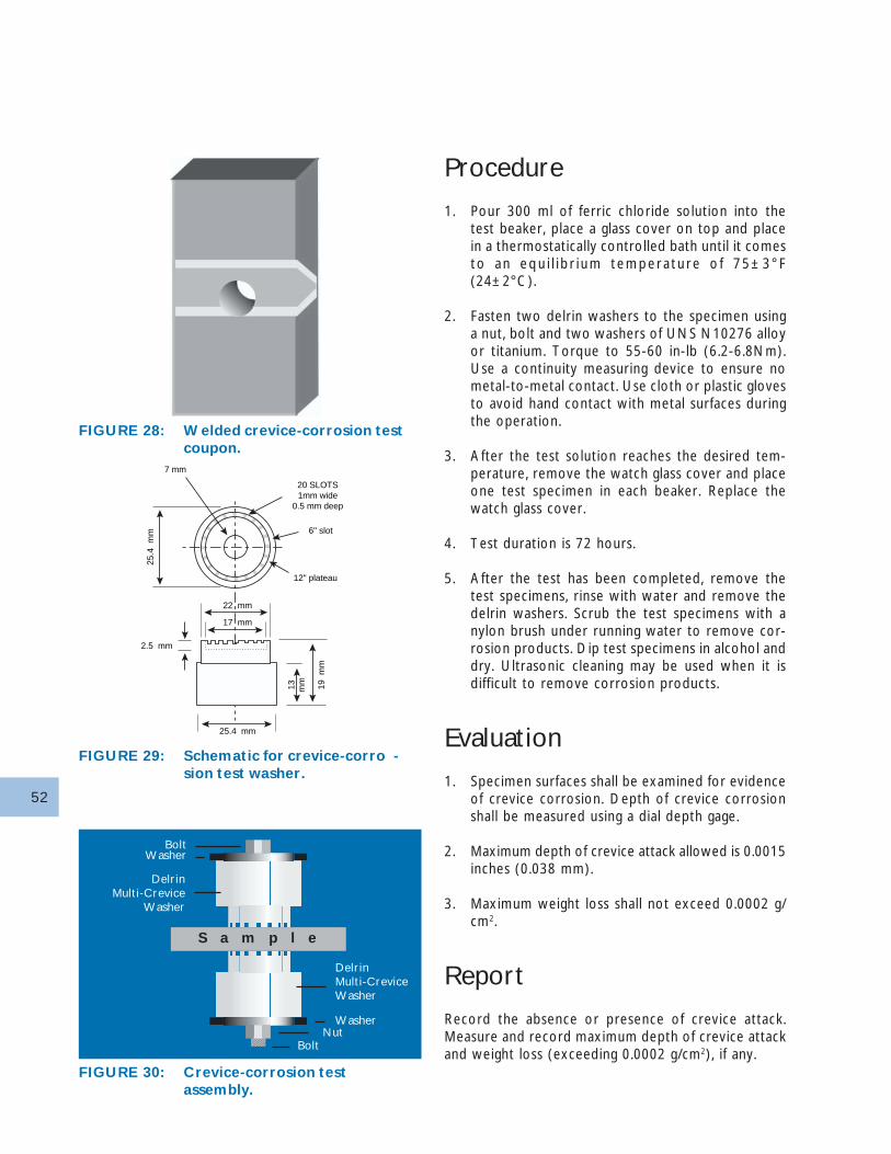
52
Procedure
1. Pour 300 ml of ferric chloride solution into thetest beaker, place a glass cover on top and placein a thermostatically controlled bath until it comesto an equ i l i b r i um tempera tu re o f 75±3°F(24±2°C).
2. Fasten two delrin washers to the specimen usinga nut, bolt and two washers of UNS N10276 alloyor titanium. Torque to 55-60 in-lb (6.2-6.8Nm).Use a continuity measuring device to ensure nometal-to-metal contact. Use cloth or plastic glovesto avoid hand contact with metal surfaces duringthe operation.
3. After the test solution reaches the desired tem-perature, remove the watch glass cover and placeone test specimen in each beaker. Replace thewatch glass cover.
4. Test duration is 72 hours.
5. After the test has been completed, remove thetest specimens, rinse with water and remove thedelrin washers. Scrub the test specimens with anylon brush under running water to remove cor-rosion products. Dip test specimens in alcohol anddry. Ultrasonic cleaning may be used when it isdifficult to remove corrosion products.
Evaluation
1. Specimen surfaces shall be examined for evidenceof crevice corrosion. Depth of crevice corrosionshall be measured using a dial depth gage.
2. Maximum depth of crevice attack allowed is 0.0015inches (0.038 mm).
3. Maximum weight loss shall not exceed 0.0002 g/cm2.
Report
Record the absence or presence of crevice attack.Measure and record maximum depth of crevice attackand weight loss (exceeding 0.0002 g/cm2), if any.
20 SLOTS1mm wide
0.5 mm deep
6" slot
12" plateau
7 mm
22 mm
17 mm
25.4 mm
2.5 mm
25.4
mm
19 m
m
mm13
FIGURE 28: Welded crevice-corrosion testcoupon.
FIGURE 29: Schematic for crevice-corro -sion test washer.
FIGURE 30: Crevice-corrosion testassembly.
BoltWasher
DelrinMulti-Crevice
Washer
S a m p l e
DelrinMulti-CreviceWasher
WasherNut
Bolt
53
Equipment Calibration
All measuring equipment utilized in this procedureshould be properly calibrated and/or checked as to astandard procedure.
Appendix B - Detection andRemoval of Iron or ScaleEmbedded in a Surface
For large-scale testing, a solution of 1% chemically puresodium chloride is suitable. After 12 to 24 hours inthis dilute salt solution, iron particles are easily de-tected by the presence of rust spots. A salt spray mayalso be used, instead of immersing the entire workpiecein the solution.
The ferroxyl test for free iron, ASTM method A 380section 7.3.4, works well for small-scale testing . Thetest is carried out by applying a potassium ferricyanidesolution (Table 22) to the surface being tested.
From ASTM A 380-Cleaning and Descaling StainlessSteel:
1. Add nitric acid to distilled water and then add po-tassium ferricyanide.
2. The appearance of a blue stain within 15 seconds ofapplication (by atomizer or swab) is evidence of sur-face iron contamination. Several minutes may be re-quired for detection of oxide scale.
3. Remove the solution from the test surface as soonas possible with water or acetic acid and a fiber bristlebrush.
Appendix C- MetallographicExamination of AL-6XNAlloy
Metallographic examination of AL-6XN alloy may bedone to check for sigma phase precipitation or forgeneral structural examination. For detection of sigmaphase precipitation, a modified ASTM A 262 practiceA (oxalic acid etch test) is typically used. The modi-fied procedure differs in the following respects:
• The surface to be examined should be mechanicallypolished using standard metallographic procedures.
• The potential (rather than the current density) iscontrolled at 6 volts.
• The etching time is limited to 3 to 5 seconds.
Material which is essentially free of sigma phase, etc.,will be practically unaffected by this procedure. Uponmicroscopic examination it will present an appearancesimilar to that of the 0.180 wt% N alloy shown in Fig-ure 2. Material which contains sigma phase precipitatesshow etching of the grain boundaries similar to thatshown by the 0.050 wt% N alloy of Figure 2.
General structural examination (for determination ofgrain size, etc.) is typically performed using standardmetal lographic pol ishing procedures fol lowed bychemical etching. One etchant which has worked wellw i th AL-6XN a l loy i s a mixed ac ids (modi f iedglyceregia) reagent which is prepared and used as fol-lows:
• Concentrated reagent grade nitric acid (10 ml), glacialacetic acid (10 ml), hydrochloric acid (15 ml) andglycerol (3 ml) are mixed together and allowed tostand for approximately 5 minutes.
• The freshly polished and dried specimen is swabbedcontinuously with the mixed acids reagent for 30 to45 seconds.
• The etched specimen is then washed and driedbefore microscopic examination.
• It may be necessary to repolish and re-etch thespecimen to get a clear microstructure
• Previously etched specimens must always berepolished before further etching is attempted.
• The mixed acids reagent can generate chlorine gasand must be used within a fume hood.
54
• The mixed acids reagent should be used within 45minutes of preparation and excess reagent should bedisposed of properly.
When properly done, this etching procedure will re-veal the grain structure of AL-6XN alloy. It may alsoreveal the presence of sigma or other second phases,but the previously described modified oxalic etchingprocedure typically provides better definition in suchcases.
Appendix D - Disclaimers
General
The data and information in this sourcebook are be-lieved to be reliable. However, this sourcebook is notintended as a substitute for competent professionalengineering assistance which is a requisite to any spe-cific application. Allegheny Ludlum Corporation makesno expressed or implied warranty and assumes no le-gal responsibility for results to be obtained in any par-ticular situation and shall not be liable for any direct,indirect, special, or consequential damages.
Referenced data are typical and should not be con-strued as maximum or minimum values for specifica-tion or for final design. Data on any par ticular pieceof material may vary from those shown above.
This sourcebook is subject to revision without priornotice.
Safety in Testing and Fabrication
The tests, fabrication procedures and applications de-scribed may involve hazardous materials, operationsand equipment. This sourcebook does not purport toaddress any of the safety problems associated with thetesting, fabrication or use of AL-6XN alloy. Appropri-ate safety and health practices must be established todetermine the applicability of regulatory limitationsprior to testing, fabrication or use of AL-6XN alloy.
Hazardous Material Warning
AL-6XN alloy presents no health hazard unless it iswelded, burned, ground, or cut. During such procedures,it is possible that hazardous fumes or dusts may be
generated. Any operation must be evaluated by a com-petent health professional to determine whether ahazard exists.More complete information is available in the MaterialSafety Data Sheet for Category III-N: 330, 336, 337,800, 904L.
AL-6XN® alloy products are covered by U. S. PatentNo. 4,545,826.
Revision History
Edition 1: J. R. Kearns, 1990.Revision 1: J. R. Maurer, 1991.Edition 2: J. F. Grubb, 1995.Edition 3: J. F. Grubb & D. E. Deemer 2002
For Additional Information, Please Contact:
Allegheny Ludlum CorporationSix PPG PlacePittsburgh, PA 15222-5479412-394-2800412-394-3033 - Fax
Allegheny Ludlum Technical CenterBrackenridge, PA 15014-1597USA724-226-5000724-226-5067 - Fax800-258-3586 - Tollfree (Sheet)800-289-7528 - Tollfree (Plate)
Allvac2020 Ashcraft AvenueP.O. Box 5030Monroe, NC 28111-5030USA704-289-4511704-289-4018 - Fax800-537-5551 - Tollfree
TrademarksThe Starburst Logo, AL-6XN, AL 29-4C and E-Briteare registered trademarks and AL-6XN PLUS is atrademark of ATI Proper ties, Inc.
55
IndexAcid Cleaning, 47Alkaline Solutions, 21Annealing, Bright, 33Annealing, Maximum Temperature, 29Annealing, Minimum Temperature, 29Annealing, Open-Air, 29Annealing, Time at Temperature, 29Applications, 2, 10-13ASME Design Limits, 5ASME Maximum Allowable Design Stresses, 5, 9ASME Specifications, 8, 9, 30ASTM Specifications, 8,9Autogenous Welds, 39Biofouling, 23-25Bright Annealing, 33Carbides, 44Castings, 7Catastrophic Oxidation, 33Caustic Solutions, 21Chemical Composition, 3Chemical Segregation, Welds, 34, 43Chromium Depletion, 33-34, 44-48Cleaning, 47Cold Forming, 34Cold Work, Effect of, 27Corrosion, Erosion, 25Corrosion, General, 19-21Corrosion, Intergranular, 18Corrosion, Isocorrosion, 19-21Corrosion, Stress-Corrosion Cracking, 22-23Corrosion Testing, 51-53Cracking, Copper Contamination, 33, 39Crevice-Corrosion Resistance, 4-5, 14-16Crevices, Dissimilar Metals, 17Critical Crevice-Corrosion Temperature, 4, 16Critical Pitting, Temperature, 15Cryogenic Conditions, 28-29Cutting, 37Descaling, 46-47Dew Points, Bright Anneal, 33Disclaimers, 54Dissimilar Metal Crevices, 16Erosion Corrosion, 25Fatigue, 28-30Ferric Chloride Crevice-Corrosion Test, 4, 6, 15-1851-53Filler Metals, 39-40Free Iron, 46-48, 53Galvanic Compatibility, 17-18General Corrosion, 19-21
Heat Tint, 44-45Heat Treatment, 32-33Hot Forming, 34Intergranular Corrosion, 18Interpass Temperatures Welding, 42Isocorrosion, 19-21Low Carbon, 2, 3, 5, 44Machinability, 36-37Mechanical Properties, 28Metallography 53Metallurgical Stability 6-7Microbially Influenced Corrosion (MIC), 12, 23-25,42-43Nitrogen, Effect of, 5-7, 14-15, 21, 45Non-Destructive Testing Methods, Welds, 42-43Passivation, 47pH, Effect of, 17Physical Properties, 26Pickling, 47Pitting, 14-15Pitting and Crevice-Corrosion Indices, 15Pitting Potentials, 14-15Pitting Resistance Equivalent (PREn), 3, 4, 14-15Product Forms, 2, 7-8References, 49Removal of Weld Defects, 43Seawater, 5, 11, 16Secondary Phases, 3, 5-7, 18, 32-34, 44, 53-54Shielding Gas Composition, 45Sigma Phase, 3, 5-7, 33, 44, 53-54Specifications ASME, ASTM, 8-9, 30Specifications, Welding, 38Strength, 4-5, 8-9, 28-30Strength at Elevated Temperatures, 29Stress-Corrosion Cracking (SCC), 22Tensile Strengths, 5, 19-20Toughness at Subzero Temperatures, 29Tube Forming, 35Typical Arc Welding Procedure, 40-42Unmixed Zones, Welds, 43Warm Forming, 34Welding, 38-45Welding Specifications, 38
Allegheny Technologies Incorporated (NYSE:ATI) is one of the largest and most diversifiedspecialty materials producers in the world.The Company’s talented people use innovativematerials and processing technologies to offergrowing global markets a wide range of specialtymaterials solutions.
Visit http:/www.alleghenytechnologies.com
Allegheny LudlumAllegheny RodneyShanghai STALRome Metals
AllvacAllvac LtdTitanium International
WahChangTitanium IndustriesMetalworking Products
StellramLandis Threading SystemsFirth SterlingFirth MPDTungsten ProductsAlldyne Powder Technologies
Portland ForgeCasting Service
Visit our website www.alleghenyludlum.com forupdates to this brochure and othernew product informaion.
© 2002 Allegheny Ludlum Corporation
Allegheny Ludlum Corporation is a world leader in the technology,production and marketing of specialty materials - stainless steel, siliconelectr ical steels, tool steels, titanium, nickel alloys, as well as otheradvanced alloys.
Recommended