2
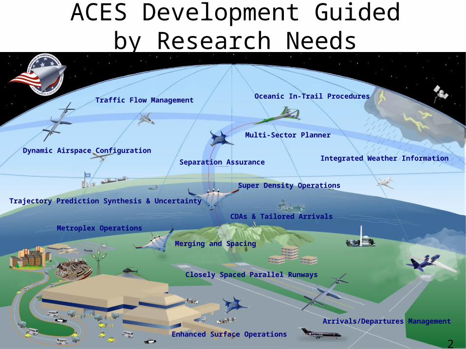
ACES Development Guided by Research Needs
2
Dynamic Airspace Configuration
Oceanic In-Trail Procedures
Integrated Weather Information
Trajectory Prediction Synthesis & Uncertainty
Traffic Flow Management
Super Density Operations
Merging and Spacing
Closely Spaced Parallel Runways
Arrivals/Departures Management
Enhanced Surface Operations
Separation AssuranceWith Arrival Merging and Separation
Metroplex Operations
CDAs & Tailored Arrivals
Multi-Sector Planner
3
Main Points• ACES development driven by research needs; Ideas from
research being folded into ACES.
• Validation based on data and not just software; emphasis on plotting, visualization, analysis with large datasets.
• Results produced by ACES are reasonable.
• ACES is faster and more stable.
• ACES has higher fidelity models (surface, terminal area trajectory, separation-assurance).
4
Outline• ACES Development:
– Separation-Assurance– Traffic Flow Management– Dynamic Airspace Configuration– Weather Data Handling– Trajectory Generators– Weight Estimation– ACES Analyst and Viewer– User Support Helpdesk
• Research Examples Using ACES:– Surface Operations– Separation-Assurance– Dynamic Airspace Configuration– Dynamic Airspace Configuration and Traffic Flow Management Integration– System-Wide Study
5
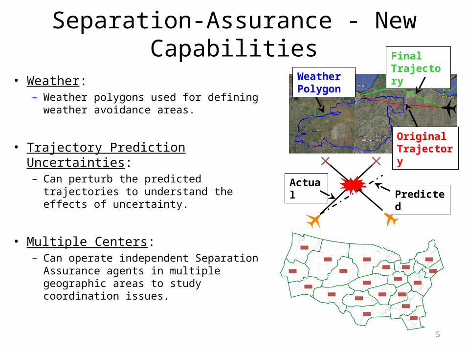
Separation-Assurance - New Capabilities
• Weather: – Weather polygons used for defining
weather avoidance areas.
• Trajectory Prediction Uncertainties:– Can perturb the predicted trajectories to
understand the effects of uncertainty.
• Multiple Centers: – Can operate independent Separation
Assurance agents in multiple geographic areas to study coordination issues.
Original Trajectory
Final Trajectory
Weather Polygon
PredictedActual
6
Traffic Flow Management Support• Objective:
– Flexible structure• Disable TFM for open-loop simulations.• Enable/disable TFM in airport, TRACON, center domains.
– Support for alternative algorithms• Distributed TFM• Centralized TFM• Linear-Programming based Optimal TFM
– Causality and delay attribution• Who caused it and where was it realized.
• Approach: – Support services for demand and capacity prediction.– Improved plug-in architecture.– Messaging interface.– Simple GUI based configuration prior to simulation.
7
Dynamic Airspace Configuration Support
• Objective: – Implement Dynamic Airspace Configuration algorithms in ACES.– Support for capacity (including workload) metrics.
• Approach: – Data interface for ACES traffic and geometry outputs in Enhanced
Traffic Management System (ETMS) format.– Communications service for data exchange with DAC algorithms
running on other computers. – ACES modified to read back subsector data (sector building blocks).
8
Weather Service Provider Support
• Objective: – Support for dynamic convective weather products.
– Support for forecast weather products.– Support for grid-based and contour-based weather data.
• Approach: – Unified service interface for querying weather data.– Error models for weather forecast from nowcast data when forecast
data are unavailable.• Time-shift error• Position error• Severity and coverage error
9
• Objective: – Airport to airport trajectory generation.
• Surface• Terminal area• Enroute
– Choice of trajectory generators.
• Approach: – Swappable trajectory generator interface.– Kinematic trajectory generator uses BADA performance tables.– Kinetic trajectory generator uses BADA aircraft performance data and
atmosphere data.
• Key Finding: – New trajectory generators being tested. – Performance data updated based on BADA 3.7.– Will improve ACES runtime performance.
Trajectory Generators
10
• Objective: – Determine takeoff weight for planned flight using aircraft performance
model, and reserve and maneuvering fuel requirement.
• Approach: – Iterative procedure to determine fuel and payload.– A closed-form solution based on constant altitude cruise, and climb and
descent fuel increment factors.
• Key Finding: – Payload-range curves compare well with aircraft manufacturer published
data.– Computationally efficient.
Take-Off Weight Estimation
11
ACES Analyst Tool Enhancements• ACES Grid Creator
– Generation of sector grid maps from ETMS sector files.
• ACES Disambiguation Tool– Bug fixes and compatibility
enhancements for use with the ACES Grid Creator.
– • ACES Analyst
– Flight data set from ETMS data.– Multiple data converters to
support scenario generation.– Analyst reports.
• ACES Report Generator– Enhances to generate .csv file
versions of the ACES National Metrics.
– Analyst reports.
• ACES Viewer– Replaces the current ACES VST
during runtime.
• ACES-SA Web Application– Viewing and analyzing conflict
resolution.
• SurfTools– Airport surface design tool
(STLE) – STLE is part of ACES.
• TASSE– ACES runtime configuration
management system and surface and terminal area airspace design tool.
12
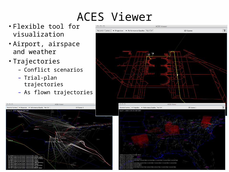
ACES Viewer• Flexible tool for
visualization• Airport, airspace and
weather• Trajectories
– Conflict scenarios– Trial-plan trajectories– As flown trajectories
13
User Support Helpdesk• Purpose of the ACES Helpdesk :
– A single point of contact for answering ACES questions.
• Helpdesk Queries:– Users send email queries to
[email protected].– Each query assigned a unique tracking number. – Communication via email, using the tracking number, until
query resolved.
• Common queries during the first two months:– Locating ACES documentation.– ACES setup questions.

14
Research Examples
15
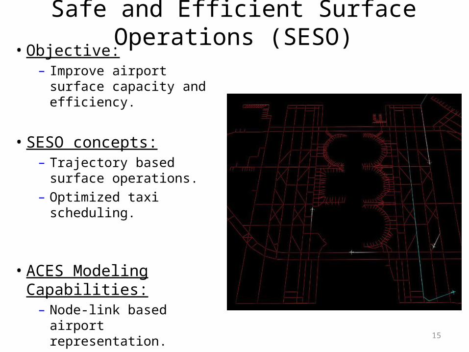
Safe and Efficient Surface Operations (SESO)• Objective:
– Improve airport surface capacity and efficiency.
• SESO concepts:– Trajectory based surface
operations.– Optimized taxi scheduling.
• ACES Modeling Capabilities:– Node-link based airport
representation.– Time based taxi routes.– Integrated airport/TRACON
simulation environment.
16
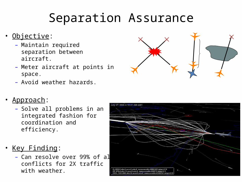
Separation Assurance• Objective:
– Maintain required separation between aircraft.
– Meter aircraft at points in space. – Avoid weather hazards.
• Approach: – Solve all problems in an
integrated fashion for coordination and efficiency.
• Key Finding: – Can resolve over 99% of all
conflicts for 2X traffic with weather.
17
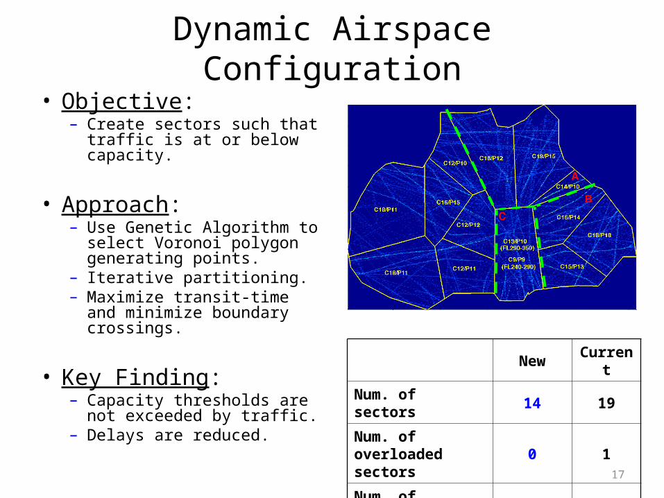
Dynamic Airspace Configuration• Objective:
– Create sectors such that traffic is at or below capacity.
• Approach: – Use Genetic Algorithm to
select Voronoi polygon generating points.
– Iterative partitioning.– Maximize transit-time and
minimize boundary crossings.
• Key Finding: – Capacity thresholds are not
exceeded by traffic.– Delays are reduced.
New Current
Num. of sectors 14 19
Num. of overloaded sectors 0 1
Num. of boundary crossings 2,471 2,851
18
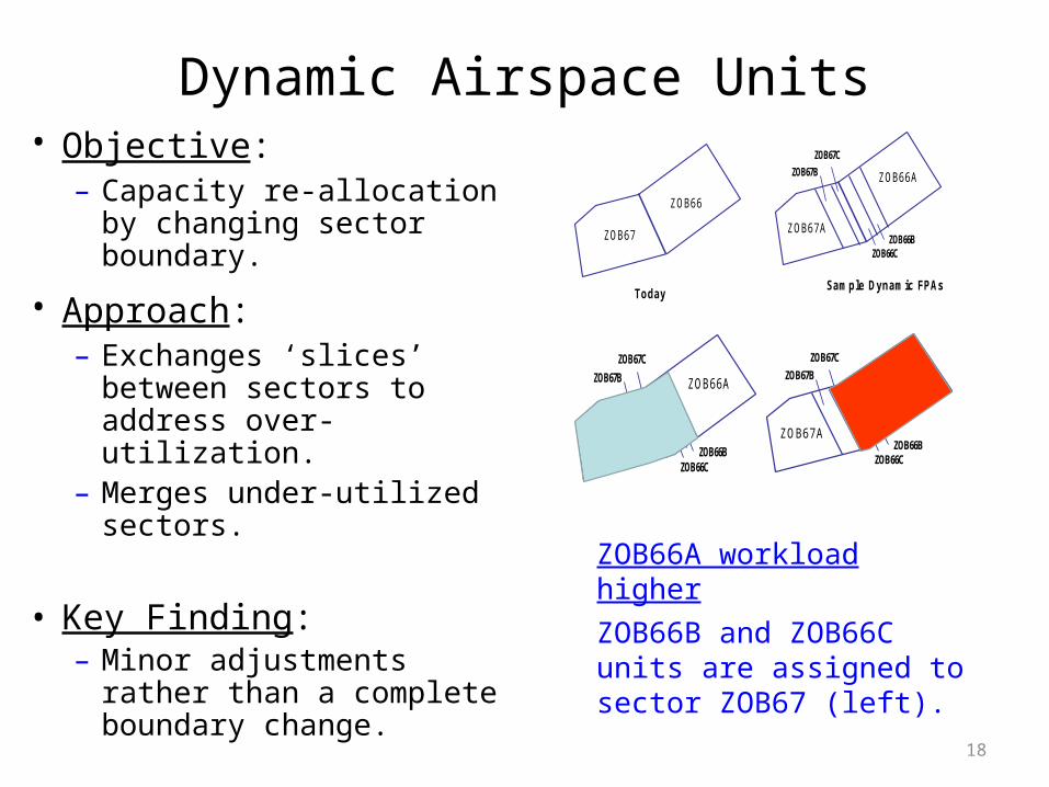
Dynamic Airspace Units• Objective: – Capacity re-allocation by
changing sector boundary.
• Approach: – Exchanges ‘slices’ between
sectors to address over-utilization.
– Merges under-utilized sectors.
• Key Finding: – Minor adjustments rather
than a complete boundary change.
ZOB66A workload higherZOB66B and ZOB66C units are assigned to sector ZOB67 (left).
ZOB67
ZOB66
TodaySample Dynamic FPAs
ZOB67A
ZOB66A
ZOB66BZOB66C
ZOB67C
ZOB67B
Sample Dynamic FPAs
ZOB67A
ZOB66A
ZOB66BZOB66C
ZOB67C
ZOB67B
Sample Dynamic FPAs
ZOB67A
ZOB66A
ZOB66BZOB66C
ZOB67C
ZOB67B
19
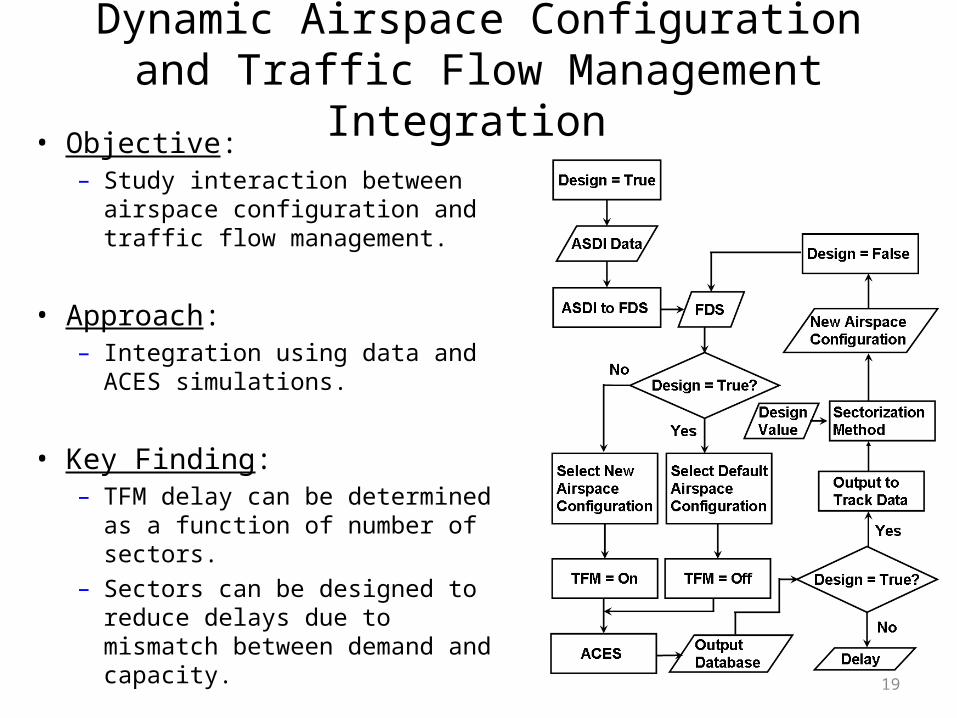
Dynamic Airspace Configuration and Traffic Flow Management Integration
• Objective: – Study interaction between airspace
configuration and traffic flow management.
• Approach: – Integration using data and ACES
simulations.
• Key Finding: – TFM delay can be determined as a
function of number of sectors.– Sectors can be designed to reduce
delays due to mismatch between demand and capacity.
20
System-Wide Weather Effect Study
• Objective: – Establish weather affected baseline data for common scenario days.– Determine yearly weather delays for current day operations. – Assess the ability of Separation-Assurance, Traffic Flow Management
and Dynamic Airspace Configuration to reduce delay in the presence of weather.
• Approach: – 17 days of traffic, wind, weather, AAR/ADR, FAA data from 2006
collected.• Traffic volume: low and high• Weather: light, moderate and severe
– Average arrival delay with 2006, 2018 and 2025 assumed traffic and capacities computed.
21
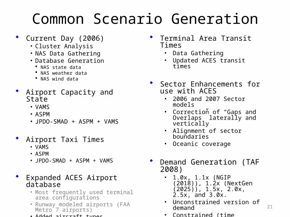
Common Scenario Generation Current Day (2006)
• Cluster Analysis• NAS Data Gathering• Database Generation
NAS state data NAS weather data NAS wind data
Airport Capacity and State• VAMS• ASPM• JPDO-SMAD + ASPM + VAMS
Airport Taxi Times• VAMS• ASPM• JPDO-SMAD + ASPM + VAMS
Expanded ACES Airport database• Most frequently used terminal area
configurations• Runway modeled airports (FAA Metro 7
airports)• Added aircraft types
Terminal Area Transit Times• Data Gathering• Updated ACES transit times
Sector Enhancements for use with ACES• 2006 and 2007 Sector models• Correction of “Gaps and Overlaps”
laterally and vertically • Alignment of sector boundaries• Oceanic coverage
Demand Generation (TAF 2008)• 1.0x, 1.1x (NGIP (2018)), 1.2x
(NextGen (2025)), 1.5x, 2.0x, 2.5x, and 3.0x.
• Unconstrained version of demand• Constrained (time shifted) version of
demand
NGIP (2018) configuration
NextGen (2025) configuration
22
Parting Thoughts
• ACES development driven by research needs; Ideas from research being folded into ACES.
• Validation based on data and not just software; emphasis on plotting, visualization, analysis with large datasets.
• Results produced by ACES are reasonable.
• ACES is faster and more stable.
• ACES has higher fidelity models (surface, terminal area trajectory, separation assurance).
Recommended


![[Bankim Chandra Chatterji] Anandamath(Bookos.org)](https://img.pdfslide.us/doc/110x75/55cf9a77550346d033a1e052/bankim-chandra-chatterji-anandamathbookosorg.jpg)