FVXS-F
F l o o r S t a n d i n g U n i t
Air Conditioners
Technical Data
w w w . d a i k i n . e u
FVXS-F
F l o o r S t a n d i n g U n i t
Air Conditioners
Technical Data
w w w . d a i k i n . e u
• Split Sky Air • Indoor units 1
• Indoor units • R-410A • FVXS-FV1B
TABLE OF CONTENTSFVXS-FV1B
1 Features . . . . . . . . . . . . . . . . . . . . . . . . . . . . . . . . . . . . . . . . . . . . . . . . . . . . . . . . . . . . . 2
2 Specifications . . . . . . . . . . . . . . . . . . . . . . . . . . . . . . . . . . . . . . . . . . . . . . . . . . . . . . . 3
For indoor units only . . . . . . . . . . . . . . . . . . . . . . . . . . . . . . . . . . . . . . . . . . . . . . . . . 3
Technical Specifications . . . . . . . . . . . . . . . . . . . . . . . . . . . . . . . . . . . . . . . . . . . . . 3
Electrical Specifications . . . . . . . . . . . . . . . . . . . . . . . . . . . . . . . . . . . . . . . . . . . . . . 4
3 Dimensional drawing & centre of gravity . . . . . . . . . . . . . . . . . . . . . . . . 5
Dimensional drawing . . . . . . . . . . . . . . . . . . . . . . . . . . . . . . . . . . . . . . . . . . . . . . . . . 5
Centre of gravity . . . . . . . . . . . . . . . . . . . . . . . . . . . . . . . . . . . . . . . . . . . . . . . . . . . . . 6
4 Piping diagram. . . . . . . . . . . . . . . . . . . . . . . . . . . . . . . . . . . . . . . . . . . . . . . . . . . . . . 7
5 Wiring diagram. . . . . . . . . . . . . . . . . . . . . . . . . . . . . . . . . . . . . . . . . . . . . . . . . . . . . . 8
Wiring diagram . . . . . . . . . . . . . . . . . . . . . . . . . . . . . . . . . . . . . . . . . . . . . . . . . . . . . . . 8
6 Sound data . . . . . . . . . . . . . . . . . . . . . . . . . . . . . . . . . . . . . . . . . . . . . . . . . . . . . . . . . . 9
Sound pressure spectrum . . . . . . . . . . . . . . . . . . . . . . . . . . . . . . . . . . . . . . . . . . . . 9
!
• Indoor units • R-410A • FVXS-FV1B
• Split Sky Air • Indoor units2
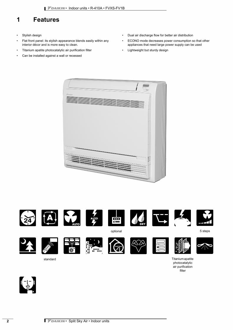
1 Features
Indoor unit Split Sky FVXS-FV1B R-410A • Stylish design
• Flat front panel: its stylish appearance blends easily within any interior décor and is more easy to clean.
• Titanium apatite photocatalytic air purification filter
• Can be installed against a wall or recessed
• Dual air discharge flow for better air distribution
• ECONO mode decreases power consumption so that other appliances that need large power supply can be used
• Lightweight but sturdy design
optional 5 steps
standard Titanium apatite photocatalytic air purification
filter
• Split Sky Air • Indoor units 3
• Indoor units • R-410A • FVXS-FV1B
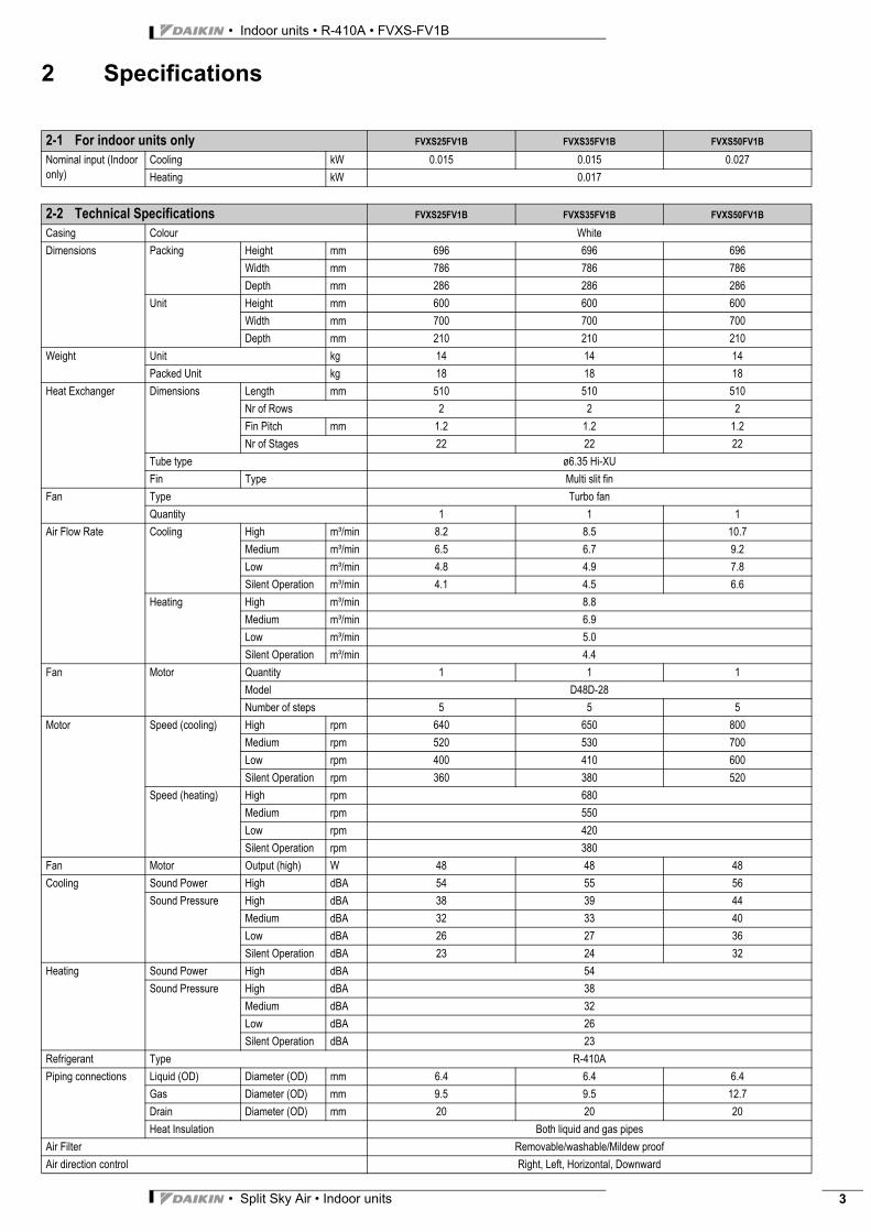
2 Specifications
2-1 For indoor units only FVXS25FV1B FVXS35FV1B FVXS50FV1B
Nominal input (Indoor only)
Cooling kW 0.015 0.015 0.027
Heating kW 0.017
2-2 Technical Specifications FVXS25FV1B FVXS35FV1B FVXS50FV1B
Casing Colour White
Dimensions Packing Height mm 696 696 696
Width mm 786 786 786
Depth mm 286 286 286
Unit Height mm 600 600 600
Width mm 700 700 700
Depth mm 210 210 210
Weight Unit kg 14 14 14
Packed Unit kg 18 18 18
Heat Exchanger Dimensions Length mm 510 510 510
Nr of Rows 2 2 2
Fin Pitch mm 1.2 1.2 1.2
Nr of Stages 22 22 22
Tube type ø6.35 Hi-XU
Fin Type Multi slit fin
Fan Type Turbo fan
Quantity 1 1 1
Air Flow Rate Cooling High m³/min 8.2 8.5 10.7
Medium m³/min 6.5 6.7 9.2
Low m³/min 4.8 4.9 7.8
Silent Operation m³/min 4.1 4.5 6.6
Heating High m³/min 8.8
Medium m³/min 6.9
Low m³/min 5.0
Silent Operation m³/min 4.4
Fan Motor Quantity 1 1 1
Model D48D-28
Number of steps 5 5 5
Motor Speed (cooling) High rpm 640 650 800
Medium rpm 520 530 700
Low rpm 400 410 600
Silent Operation rpm 360 380 520
Speed (heating) High rpm 680
Medium rpm 550
Low rpm 420
Silent Operation rpm 380
Fan Motor Output (high) W 48 48 48
Cooling Sound Power High dBA 54 55 56
Sound Pressure High dBA 38 39 44
Medium dBA 32 33 40
Low dBA 26 27 36
Silent Operation dBA 23 24 32
Heating Sound Power High dBA 54
Sound Pressure High dBA 38
Medium dBA 32
Low dBA 26
Silent Operation dBA 23
Refrigerant Type R-410A
Piping connections Liquid (OD) Diameter (OD) mm 6.4 6.4 6.4
Gas Diameter (OD) mm 9.5 9.5 12.7
Drain Diameter (OD) mm 20 20 20
Heat Insulation Both liquid and gas pipes
Air Filter Removable/washable/Mildew proof
Air direction control Right, Left, Horizontal, Downward
• Indoor units • R-410A • FVXS-FV1B
• Split Sky Air • Indoor units4
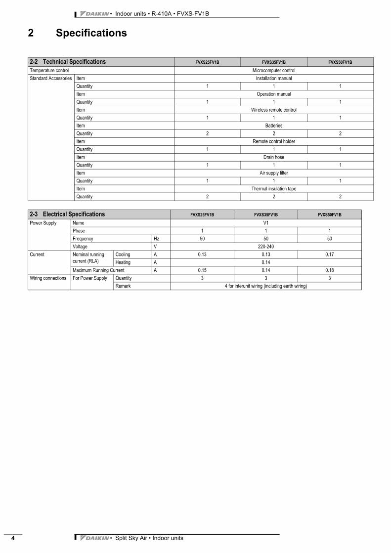
2 Specifications
Temperature control Microcomputer control
Standard Accessories Item Installation manual
Quantity 1 1 1
Item Operation manual
Quantity 1 1 1
Item Wireless remote control
Quantity 1 1 1
Item Batteries
Quantity 2 2 2
Item Remote control holder
Quantity 1 1 1
Item Drain hose
Quantity 1 1 1
Item Air supply filter
Quantity 1 1 1
Item Thermal insulation tape
Quantity 2 2 2
2-3 Electrical Specifications FVXS25FV1B FVXS35FV1B FVXS50FV1B
Power Supply Name V1
Phase 1 1 1
Frequency Hz 50 50 50
Voltage V 220-240
Current Nominal running current (RLA)
Cooling A 0.13 0.13 0.17
Heating A 0.14
Maximum Running Current A 0.15 0.14 0.18
Wiring connections For Power Supply Quantity 3 3 3
Remark 4 for interunit wiring (including earth wiring)
2-2 Technical Specifications FVXS25FV1B FVXS35FV1B FVXS50FV1B
• Split Sky Air • Indoor units 5
• Indoor units • R-410A • FVXS-FV1B
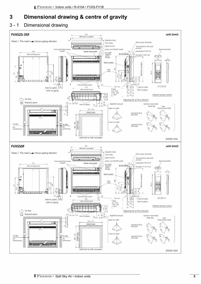
3 Dimensional drawing & centre of gravity
3 - 1 Dimensional drawing
3D056135
FVXS25-35F unit (mm)
Main unit fixing screw
Note) 1. The mark (Y) shows piping direction
Main unit fixed screws
666 (half concealed)
Operation lamp
Timer lamp
Indoor unit ON/OFF switch
Signal receiver
Air outletselectionswitch(Inside)
Name plate
Drainsocket
Front panel fixed screws
Hole for splintHole for piping
Air flow
Required space
(formaintenance)
(forperformance)
(Wall hole)
Wall hole for half concealed
Terminal block with earthterminal
Liquid pipe (J6.4 CuT)
Gas pipe (J9.5 CuT)
Room temp. thermistor
Signal transmitter
Infrared remote control
Hole for splint
Hole for piping
Drain hose
Adjusting the air flow direction
Right/left (manual)
Upper air outlet
Lower air outlet
Upward air flowlimit (OFF)
Upward air flowlimit (ON)
Up/down (automatic)Heat
(Heat pump model)
Hole for piping
Forp
erfo
rman
ce
584
(hal
fcon
ceal
ed)
(Wal
lhol
e)
Front panel fixed screws(inside)
VP20I.D. J20O.D. J26L 220
50 MIN 50 MIN
Cooling / dry
A
Model name label
95 (Half concealed)
85
Cool, dry
3D056136
FVXS50F unit (mm)
Main unit fixing screw
Note) 1. The mark (Y) shows piping direction
Main unit fixed screws
666 (half concealed)
Operation lamp
Timer lamp
Indoor unit ON/OFF switch
Signal receiver
Air outletselectionswitch(Inside)
Name plate
Drainsocket
Front panel fixed screws
Hole for splintHole for piping
Air flow
Required space
(formaintenance)
(forperformance)
(Wall hole)
Wall hole for half concealed
Terminal block with earthterminal
Liquid pipe (J6.4 CuT)
Gas pipe (J12.7 CuT)
Room temp. thermistor
Signal transmitter
Infrared remote control
Hole for splint
Hole for piping
Drain hose
Adjusting the air flow direction
Right/left (manual)
Upper air outlet
Lower air outlet
Upward air flowlimit (OFF)
Upward air flowlimit (ON)
Up/down (automatic)Cooling / dry Heat
(Heat pump model)
Hole for piping
Forp
erfo
rman
ce
584
(hal
fcon
ceal
ed)
(Wal
lhol
e)
Front panel fixed screws(inside)
VP20I.D. J20O.D. J26L 220
50 MIN 50 MIN
A
Model name label
95 (Half concealed)
85
Cool, dry
• Indoor units • R-410A • FVXS-FV1B
• Split Sky Air • Indoor units6
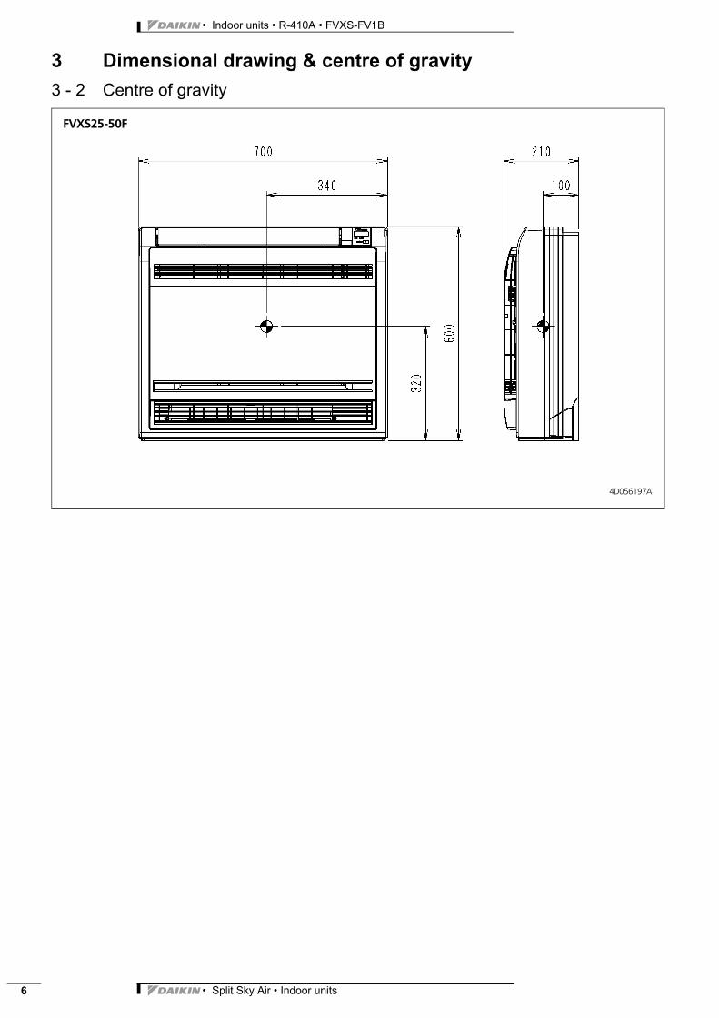
3 Dimensional drawing & centre of gravity
3 - 2 Centre of gravity
FVXS25-50F
4D056197A
• Split Sky Air • Indoor units 7
• Indoor units • R-410A • FVXS-FV1B
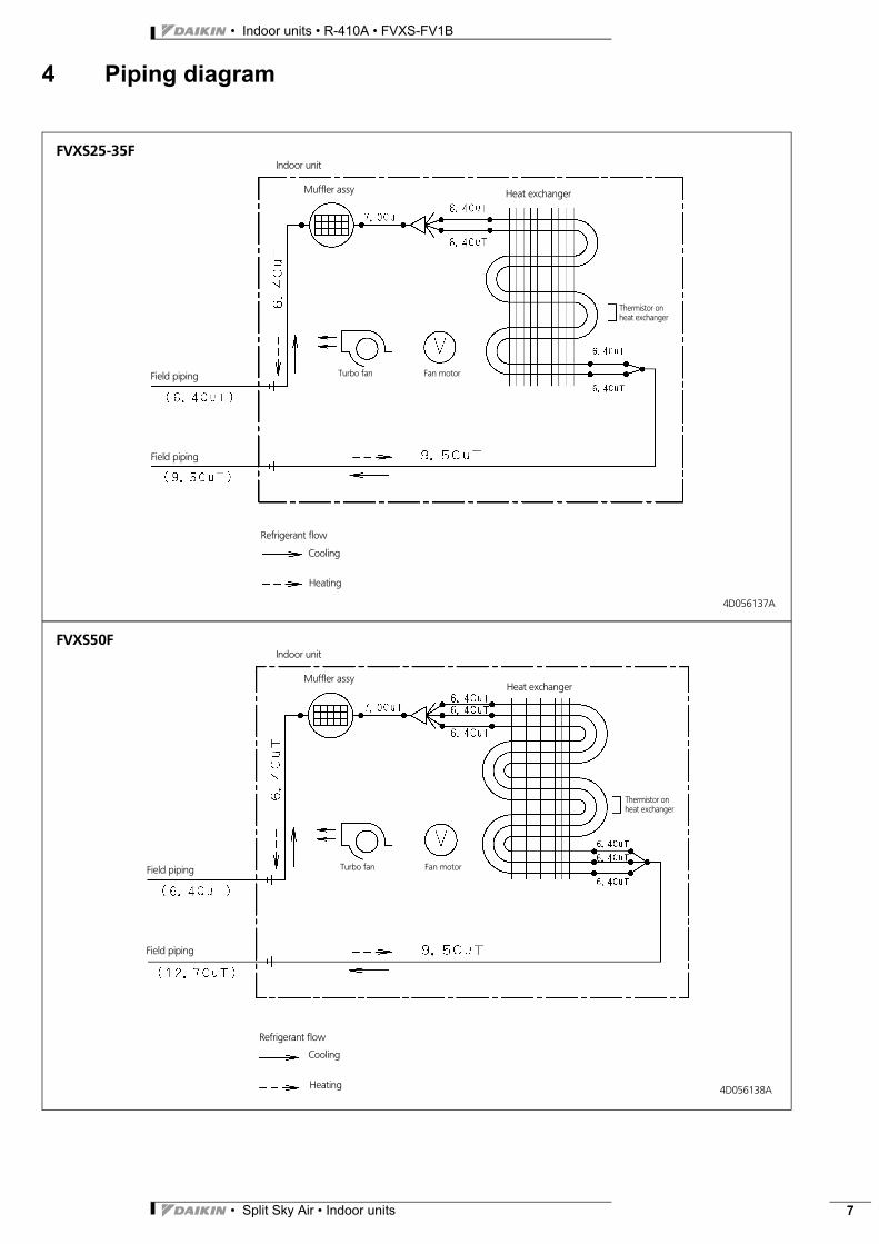
4 Piping diagram
FVXS25-35FIndoor unit
Heat exchanger
Fan motorField piping
Field piping
Refrigerant flow
Cooling
Heating
Turbo fan
Thermistor onheat exchanger
Muffler assy
4D056137A
FVXS50FIndoor unit
Heat exchanger
Fan motorField piping
Field piping
Refrigerant flow
Cooling
Heating
Turbo fan
Thermistor onheat exchanger
Muffler assy
4D056138A
• Indoor units • R-410A • FVXS-FV1B
• Split Sky Air • Indoor units8
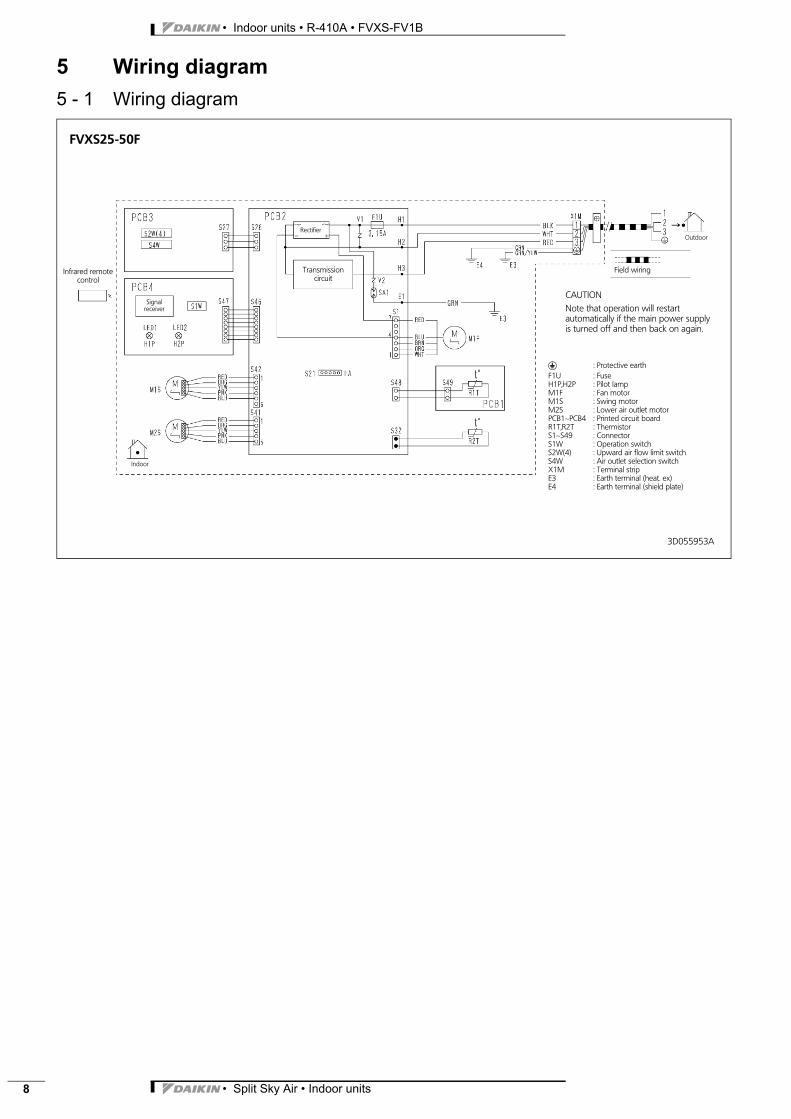
5 Wiring diagram
5 - 1 Wiring diagram
FVXS25-50F
gField wiring
Outdoor
Indoor
R : Protective earthF1U : FuseH1P,H2P : Pilot lampM1F : Fan motorM1S : Swing motorM2S : Lower air outlet motorPCB1∼PCB4 : Printed circuit boardR1T,R2T : ThermistorS1∼S49 : ConnectorS1W : Operation switchS2W(4) : Upward air flow limit switchS4W : Air outlet selection switchX1M : Terminal stripE3 : Earth terminal (heat. ex)E4 : Earth terminal (shield plate)
Signalreceiver
Infrared remotecontrol
Transmissioncircuit
Rectifier
CAUTIONNote that operation will restartautomatically if the main power supplyis turned off and then back on again.
3D055953A
• Split Sky Air • Indoor units 9
• Indoor units • R-410A • FVXS-FV1B
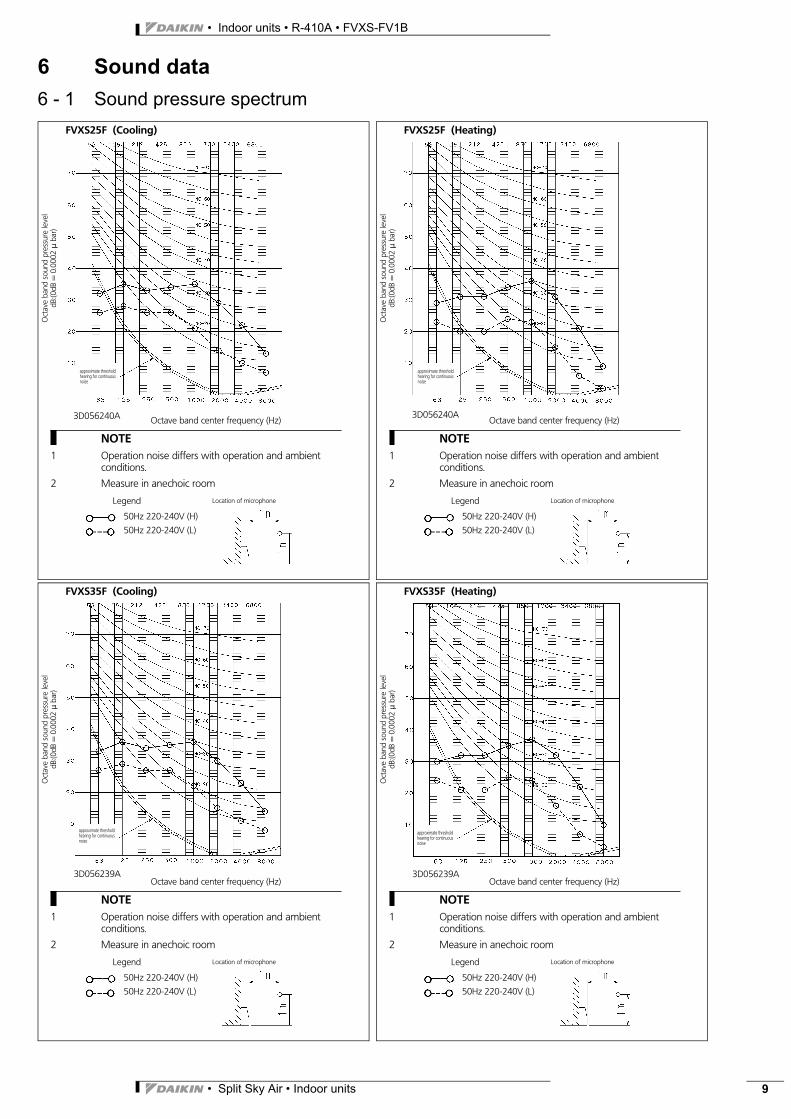
6 Sound data
6 - 1 Sound pressure spectrum
Oct
ave
band
soun
dpr
essu
rele
vel
dB:(0
dB=
0.00
02μ
bar)
Octave band center frequency (Hz)
FVXS25F (Cooling)
approximate thresholdhearing for continuousnoise
Legend
50Hz 220-240V (H)
50Hz 220-240V (L)
NOTE1 Operation noise differs with operation and ambient
conditions.
2 Measure in anechoic room
Location of microphone
3D056240A
Oct
ave
band
soun
dpr
essu
rele
vel
dB:(0
dB=
0.00
02μ
bar)
Octave band center frequency (Hz)
FVXS25F (Heating)
approximate thresholdhearing for continuousnoise
Legend
50Hz 220-240V (H)
50Hz 220-240V (L)
NOTE1 Operation noise differs with operation and ambient
conditions.
2 Measure in anechoic room
Location of microphone
3D056240A
Oct
ave
band
soun
dpr
essu
rele
vel
dB:(0
dB=
0.00
02μ
bar)
Octave band center frequency (Hz)
FVXS35F (Cooling)
approximate thresholdhearing for continuousnoise
Legend
50Hz 220-240V (H)
50Hz 220-240V (L)
NOTE1 Operation noise differs with operation and ambient
conditions.
2 Measure in anechoic room
Location of microphone
3D056239A
Oct
ave
band
soun
dpr
essu
rele
vel
dB:(0
dB=
0.00
02μ
bar)
Octave band center frequency (Hz)
FVXS35F (Heating)
approximate thresholdhearing for continuousnoise
Legend
50Hz 220-240V (H)
50Hz 220-240V (L)
NOTE1 Operation noise differs with operation and ambient
conditions.
2 Measure in anechoic room
Location of microphone
3D056239A
• Indoor units • R-410A • FVXS-FV1B
• Split Sky Air • Indoor units10
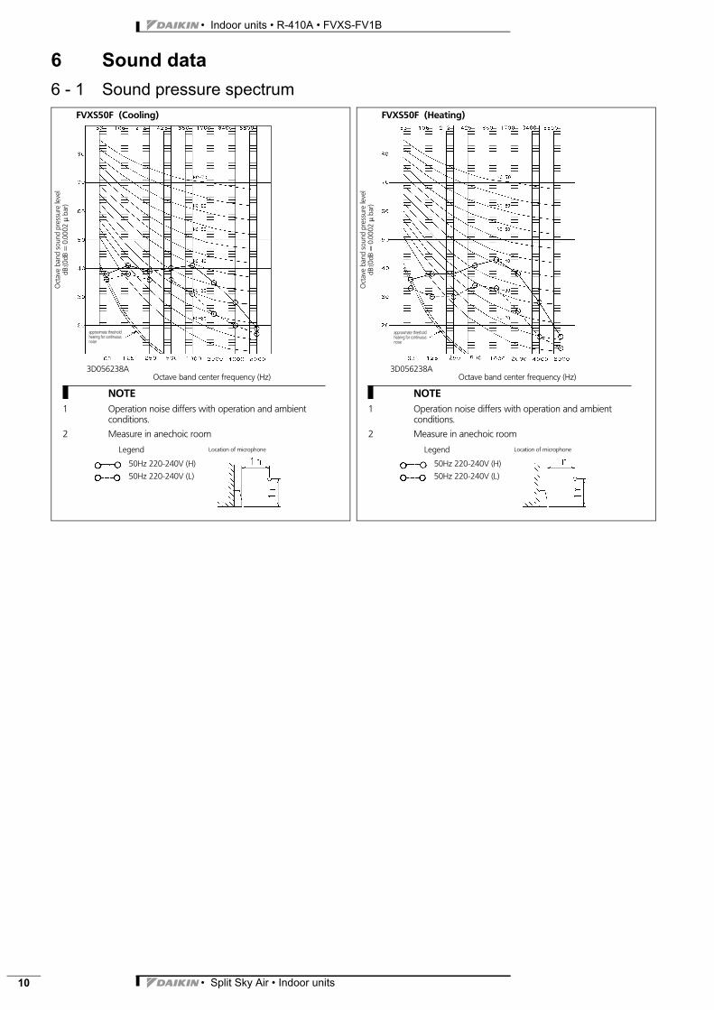
6 Sound data
6 - 1 Sound pressure spectrum
Oct
ave
band
soun
dpr
essu
rele
vel
dB:(0
dB=
0.00
02μ
bar)
Octave band center frequency (Hz)
FVXS50F (Cooling)
approximate thresholdhearing for continuousnoise
Legend
50Hz 220-240V (H)
50Hz 220-240V (L)
NOTE1 Operation noise differs with operation and ambient
conditions.
2 Measure in anechoic room
Location of microphone
3D056238AO
ctav
eba
ndso
und
pres
sure
leve
ldB
:(0dB
=0.
0002
μba
r)Octave band center frequency (Hz)
FVXS50F (Heating)
approximate thresholdhearing for continuousnoise
Legend
50Hz 220-240V (H)
50Hz 220-240V (L)
NOTE1 Operation noise differs with operation and ambient
conditions.
2 Measure in anechoic room
Location of microphone
3D056238A

Naamloze Vennootschap - Zandvoordestraat 300, B-8400 Oostende - Belgium - www.daikin.eu - BE 0412 120 336 - RPR Oostende
Daikin’s unique position as a manufacturer of air
conditioning equipment, compressors and refrigerants
has led to its close involvement in environmental issues.
For several years Daikin has had the intention to become
a leader in the provision of products that have limited
impact on the environment. This challenge demands the
eco design and development of a wide range of products
and an energy management system, resulting in energy
conservation and a reduction of waste.
Daikin Europe N.V. is participating in the EUROVENT
Certification Programme. Products are as listed in the
EUROVENT Directory of Certified Products.
Daikin products are distributed by:
EE
DE
N1
0-1
00
• 0
4/1
0 •
Co
py
rig
ht
Da
ikin
Th
e p
rese
nt
pu
blic
ati
on
su
pe
rse
de
s E
ED
EN
09
-10
0
Pre
par
ed
in B
elg
ium
by
Lan
no
o (
ww
w.la
nn
oo
pri
nt.
be
), a
com
pan
y w
ho
se c
on
cern
for
the
en
viro
nm
en
t is
se
t in
th
e E
MA
S an
d IS
O 1
40
01
sys
tem
s.
Re
spo
nsi
ble
Ed
ito
r: D
aik
in E
uro
pe
N.V
., Z
an
dv
oo
rde
stra
at
30
0,
B-8
40
0 O
ost
en
de
The present publication is drawn up by way of information only and does not constitute an offer binding
upon Daikin Europe N.V.. Daikin Europe N.V. has compiled the content of this publication to the best of its
knowledge. No express or implied warranty is given for the completeness, accuracy, reliability or fitness for
particular purpose of its content and the products and services presented therein. Specifications are subject
to change without prior notice. Daikin Europe N.V. explicitly rejects any liability for any direct or indirect
damage, in the broadest sense, arising from or related to the use and/or interpretation of this publication. All
content is copyrighted by Daikin Europe N.V..
EN_Split_Front_Back.pdf 2 28/05/2010 15:21:37
Recommended