Air Braking Equipmentfor Towed Vehicles inAccordance with CouncilDirective 71/320/ EEC
Diagrammatic Views and Description of Braking Systems and Air Braking Equipment
2. Edition
815 000 080 3 8150000803
This publication is not subject to any update service.New versions are available in INFORM atwww.wabco-auto.com
Copyright WABCO 2004
Vehicle Control SystemsAn American Standard Company
The right of amendment is reservedVersion 002/07.03
Wabcodruck 815 010 034 3

2
Table of Contents
2
Page1. Graphic symbols 4
2. Identification of Port Connections 19
3. Recommendations for Installation for fitting standard braking systems to RREG 21
4. Description of Components 35
Please note:For Trailer ABS ”VARIO-C“, see brochures 815 000 163 3
For Vario Compact ABS ”VCS“, see brochures 815 000 242 3and VCS II 815 000 426 3
Trailer EBS, see brochure 815 000 298 3
Trailer EBS D, see brochure 815 000 420 3

3
WABCO The right partner - to be on the safe side
To bring safety to our roads - this has been WABCO’sobjective for decades. Through continuing technical in-novations in the research, development and manu- fac-turing processes, we have today achieved a leadingposition in many market segments of pneumatic andelectronic systems for commercial vehicles.
Intelligent solutions for practical operation
One example for the successful synthesis of the elec-tronics and pneumatics sectors is WABCO’s ABS brak-ing system which has for years proved its worth in actualoperation and which is being used by leading interna-tional manufacturers of commercial vehicles today.
The drive-slip control system, ASR, is another featurewhich people have now come to expect in modern com-mercial vehicles.
In the electronics sector, WABCO’s product range alsofocuses on transmission controls, on air suspension sys-tems (ECAS) for lorries and trailers, and on heating, airconditioning and ventilation controls. And in the me-chanical/pneumatics sector WABCO has made a namefor itself in compressed-air and air/hydraulic braking sys-tems, compressors, door actuators and coupling con-trols.
Success through international commitment
WABCO forms an important part in a group of compa-nies successfully operating all over the world. There areWABCO companies in Germany, Austria, Switzerland,France, the Benelux countries, Great Britain, Sweden,Italy, Spain and Brazil, and we are maintaining cooper-ating companies and joint ventures in Japan, India, andthe USA. In addition to these interlinked companies,WABCO offers a comprehensive network of sales out-lets and workshops.
WABCO Service with a capital ‘S’
A staff of close to 6,000 people ensure constant availa-bility of service and proximity to our customers. This in-cludes both the reliable supply with genuine WABCOspares for retro-fitting and repairs, and competent sup-port and advice. And of course we also offer technicaltraining on location.
Our world-wide commitment has made us one of theleading firms in the industry. It is through the compe-tence and dedication of our staff that WABCO today hasa prominent position in the industry. A position which weintend to not only maintain but to strengthen further.
With reliability, safety, quality and service, WABCO isyour partner for the future.
2
4
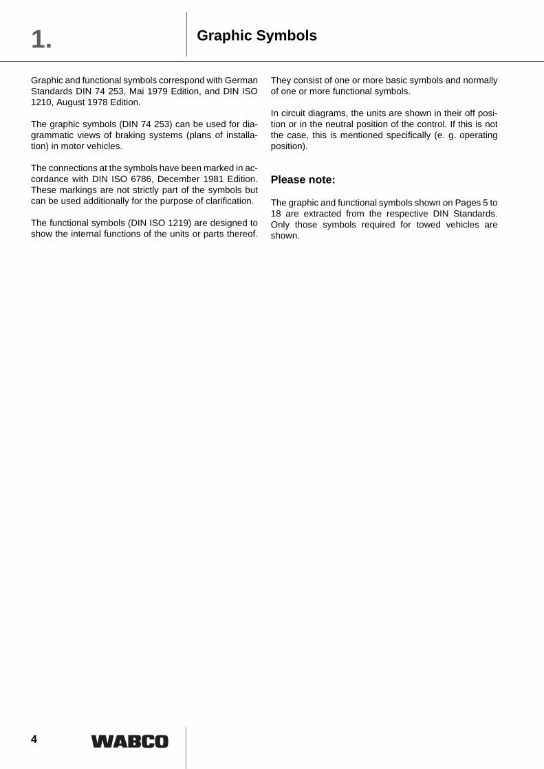
Graphic and functional symbols correspond with GermanStandards DIN 74 253, Mai 1979 Edition, and DIN ISO1210, August 1978 Edition.
The graphic symbols (DIN 74 253) can be used for dia-grammatic views of braking systems (plans of installa-tion) in motor vehicles.
The connections at the symbols have been marked in ac-cordance with DIN ISO 6786, December 1981 Edition.These markings are not strictly part of the symbols butcan be used additionally for the purpose of clarification.
The functional symbols (DIN ISO 1219) are designed toshow the internal functions of the units or parts thereof.
They consist of one or more basic symbols and normallyof one or more functional symbols.
In circuit diagrams, the units are shown in their off posi-tion or in the neutral position of the control. If this is notthe case, this is mentioned specifically (e. g. operatingposition).
Please note:
The graphic and functional symbols shown on Pages 5 to18 are extracted from the respective DIN Standards.Only those symbols required for towed vehicles areshown.
Graphic Symbols1.
2

5
Basic Symbols 1.
Graphic Symbols inaccordance with DIN 74 253
Functional Symbols inaccordance with DIN ISO 1219 Description
Marking of flow line Direction(of flow and the nature of thefluid)
Flow line
Pneumatic flow or exhaust to atmosphere)
Hydraulic flow line
Elektric flow line
Pipeline junctions:
Crossed pipelines, notconnected
Connected
Diminished cross–section inthe line (restriction)
Looped line
Flexible hose, usually con-necting moving parts(brake hose)
Coiled line(Wendelflex )R
Circle as a symbol forcom-pressors, pumps, motors,measuring instruments,mechanical links, rollers,etc.
Types of flow line:

6
Basic Symbols1.
Actuating mechanisms
Rectangle and square
as a symbol for valves,cylinders and actuators
Diamond for conditioningapparatus (filter, lubricatorseparator, heat exchanger)
Enclosure for severalcomponents assembledin one unit
Path and direction of flowthrough valves
Direction of rotation
Sloping arrow: Indication ofthe possibility of a regulation
Levers, shafts, piston rodsand mechanical connections
Detent: A device for maintaining a given position
Muscular control:by push button, by lever or by pedal (general symbol)
Rotating
Via linkage
Arrow, indication of:Direction of flow
Graphic Symbols inaccordance with DIN 74 253
Functional Symbols inaccordance with DIN ISO 1219 Description

7
Basic Symbols 1.
2) The flash arrow ( ) is not part of the symbol
2)
Muscular control:
by lever
by pedal
Control:
pneumatic
hydraulic
by different controlareas
The control paths areinside the unit
Examples for multiplecontrol:double controlby release of pressureby application of pressure
triple control
Electrical control,by solenoid valve
Slack adjuster:
manual
automatic
Pressure measurements:
Pressure gauge
Warning facilities
Graphic Symbols inaccordance with DIN 74 253
Functional Symbols inaccordance with DIN ISO 1219 Description

8
Basic Symbols and Valves1.
41 42
41 42
Test and filling coupling
12
3
1
2
3
Dual pressure gauge
Low–pressure indicator
Lamp
Buzzer
Test and filling coupling:
in a line
on the apparatus
on the apparatus withsubsequent mechanicalactuator
Filling coupling: Energytake–off is not possible
Directional control valvewith manual control
As a rule, a single square isto be used to represent thevalves
2)
Graphic Symbols inaccordance with DIN 74 253
Functional Symbols inaccordance with DIN ISO 1219 Description
2) The flash arrow ( ) is not part of the symbol

9
Valves 1.
1) In operating function, the direction of flow is shown here to be from left to right.
1 2
2
1 2
1)
1)
1)
1)
1
1 21 2
11 12 12
2 2
11
11 12
2
12
2
11
1 2 21
1 2
1 2
2
1
21
Non–return valve
Non–return valve withlimited return flow
Non–return valve withrestricted return flow(Throttle check valve)
Alternating valve withoutreturn flow(Double check valve)
Alternating valve withreturn flow(Shuttle valve)
Choke valve
Rapid exhaust valve
Pressure ratio valve, notregulating at a constantratio(Regulating valve)
Graphic Symbols inaccordance with DIN 74 253
Functional Symbols inaccordance with DIN ISO 1219 Description

10
Valves1.
1) see Page 9
1)
1 2
1)
1 2
1 2
1 2
112
12
1
2
1
21 22
21
21
21
21
2
11 12
21
211
22
Regulating at a constantratio(Pressure reducer)
Pressure relief valve:
without return flow
with limited return flow
with return flow
Double relief valve withlimited return flow
Air suspension valve:
with one bellows connection
with two non–equivalentbellows connections
Graphic Symbols inaccordance with DIN 74 253
Functional Symbols inaccordance with DIN ISO 1219 Description

11
Valves 1.
1) see Page 9
1)
1)
1
4
1 2
1 2
4
4
1 2
4
4
1
21
4+--
+--
Drain valve (Water trap):
with manual control, incontinuous line
with manual control, onreservoir
automatically drained
automatically drained withimpulse control
Safety valve
Relay valve:
with pressure reduction
with electro-magneticallycontrolled brake valve andpressure limiting device(Solenoid relay valve)
Graphic Symbols inaccordance with DIN 74 253
Functional Symbols inaccordance with DIN ISO 1219 Description

12
Valves1.
1) see Page 9
1 2
112
12
1 2
4
1)
1
2
1
2
1
2
4
4
21
+--
+--
2
11
+--
+--
12
21
4
21
21
4
2
3
4
1
Solenoid control valve
Brake valve, electro–magnetically controlled, with pressure limiting device
Empty / Load valve
Automatic load-sensingvalve:
mechanically controlledwith integral relay valve
with pneumatic or hydrauliccontrol, e. g. single-circuitpneumatic control
mechanically controlled
Graphic Symbols inaccordance with DIN 74 253
Functional Symbols inaccordance with DIN ISO 1219 Description

13
Valves 1.
12-1
2
2
1
2
12-1
2
1
(3)2-1
2
2-11
1
4
2-1
2
2-1
2
12-1
2
1 2-1
12-1
2
2
2-1
4
1
Relay emergency valve fora single-line brakingsystem:
without release valve
with release valve
with manually adjustablepressure limiting valve, e. g.with three (3) presentpressure values
with release valve and manually adjustable pressure limiting valvewithout stipulation of the number of preset pressurevalues
Relay emergency valve fora dual-line braking system:
without release valve, withadjustable lead
Graphic Symbols inaccordance with DIN 74 253
Functional Symbols inaccordance with DIN ISO 1219 Description

14
Valves1.
2
2
12-1
2
1
(3)
1
2
2-11
2
1 2-1
Relay emergency valve fora dual-line braking system:
4
1
2
2-1
4
4
21
(3)
1)
1)
221
21
1) see Page 9
2
4
1 2-1
4
1 2-1
4
2
with release valve and adjustable lead
with manually adjustablepressure limiting valvewithout stipulation of the number of preset pressurevalues
with release valve andmanually adjustable pressure limiting valve, e. g.with three (3) presetpressure values
Pressure limiting valve:
with one unlimited reliefport (21) and one limitedrelief port (22)
manually controlled, e. g.with three (3) presetpressure values
Graphic Symbols inaccordance with DIN 74 253
Functional Symbols inaccordance with DIN ISO 1219 Description

15
Cylinders 1.
1
4
11 12 11 12
11 12 11
12111211
22 21
General pneumatic actuator:(also brake chamber)
single circuit
dual circuit
with locking mechanism
Telescopic cylinder
Double acting cylinder
General hydraulic cylinder:
single circuit master cylinder,mechanically actuated
dual-circuit master cylinder,mechanically actuated
slave cylinder, single-circuit
Graphic Symbols inaccordance with DIN 74 253
Functional Symbols inaccordance with DIN ISO 1219 Description

16
Cylinders1.
11 12Hydraulic master cylinder:
dual-circuit
1112
111211
12
12 11
General spring brake actuator:
pulling, with releasemechanism at front
pushing, with releasemechanism at rear
Combination brake actuator:
pushing, pneumaticallyactuated with release mechanism at rear
pushing, pneumatically andhydraulically actuated
Servo-cylinder withhydraulic master cylinder
Graphic Symbols inaccordance with DIN 74 253
Functional Symbols inaccordance with DIN ISO 1219 Description
17
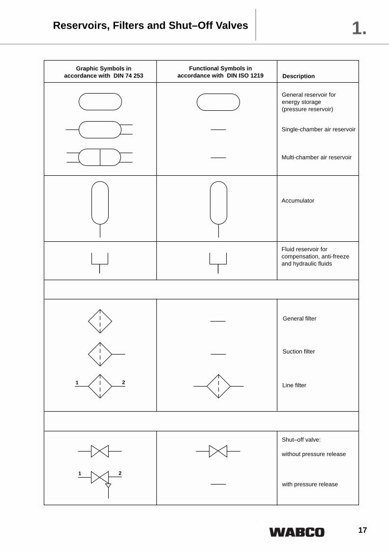
Reservoirs, Filters and Shut–Off Valves 1.
1 2
21
General reservoir for energy storage(pressure reservoir)
Single-chamber air reservoir
Multi-chamber air reservoir
Accumulator
Fluid reservoir forcompensation, anti-freezeand hydraulic fluids
Suction filter
General filter
Line filter
Shut–off valve:
without pressure release
with pressure release
Graphic Symbols inaccordance with DIN 74 253
Functional Symbols inaccordance with DIN ISO 1219 Description

18
Hose Couplings, Switches, Other Accessories1.
1
2
3
Quick–acting couplings,connected
2)
1
2
4
4
uncoupled, with open end
uncoupled, closed by freenon-return valve
closed by free non-returnvalve and two connections
Dummy coupling
connected
Blind coupling
Electric switch:
Make contact, mechanically actuated
Make contact, pneumatically actuated
Break contact, pneumaticallyactuated
Air suspension
Exhaust ports: Air bleed Exhaust to atmosphere
plain with no provision forconnection
threaded for connection
Elastic equilizing arm(Flexible arm)
Quick–acting coupling:
Graphic Symbols inaccordance with DIN 74 253
Functional Symbols inaccordance with DIN ISO 1219 Description
2) The flash arrow ( ) is not part of the symbol

19
On Units in Air Braking Systems in accordance with DIN ISO 6786For marking the port connections of units of compressedair braking systems, a standards sheet was compiled inthe FAKRA and in the ISO which was published in De-cember, 1981 as a Standard under number DIN ISO6786.
This Standard contains DIN 74 254, 04.1976 Edition, intowhich the International Standard ISO 6786, 06.1980 Edi-tion was incorporated without any alterations.
We are already gradually introducing these new mark-ings, initially for new designs and when making replace-ment casting moulds.
The main characteristics of the Standard are that theconnections on the unit
– are expressed in figures and not in letters. The reasonfor this is to prevent letters being misinterpreted inother countries.
– are not to be numbered consequtively but that theidentification digits of the connection provide informa-tion on the funcion of the unit's connection.
The identification code consists of a one or two digitnumber. The first digits mean:
0 Suction connection
1 Energy supply
2 Energy delivery (not to atmosphere, see Digit 3)
3 Exhaust
4 Pilot connection (entry into unit)
5 Spare
6 Spare
7 Anti-freeze liquid connection
8 Lubricating oil connection
9 Cooling liquid connection
A second digit may be added when several similar portconnections are available, for example in the case of splitsystems. The function represented by this second digit isleft to the discretion of the vehicle manufacturer butshould start at 1 and continue consecutively, for example21, 22, 23, etc. Exceptions are permitted when applyingthe ”building block“ principle.
The following codes are not available for free choice:
71 Anti-freeze inlet 72 Anti-freeze outlet81 Lubricating oil inlet 82 Lubricating oil outlet91 Cooling liquid inlet 92 Cooling liquid outlet
If there are a number of similar connections belonging toone unit and intended to fulfil the same function, theyshall have the same designation.
A connection which can fulfil, in any one application,more than one function, shall be identified by two (first)digits. These shall be separated by a dash (see exampleon next page).
A connection which can fulfil more than one function indifferent applications shall be identified in accordancewith agreement between the manufacturer and the cus-tomer (for example multiway valves).
The digits designated shall be placed close to the portson the units and can also be placed in the braking systemdiagram next to the identified line connections. They ap-ply to air braking systems in motor vehicles, includingthose in which the transfer is in part hydraulic, and theirtowed vehicles.
Identification of Port Connections 2.
} for compressor

20
In this example, the references signify:
1 Energy supply from the compressor 1-2 Energy supply using a valve for filling the air braking system, and energy delivery by use
of a valve as used for inflating tyres3 Connection to atmosphere (venting)21 Energy delivery to the energy accumulator (air reservoir)22 Energy delivery (switching connection)
Identification of Port Connections2.As an example, DIN ISO 6786 shows an unloadervalve with filling and switching connections.

21
Standard Braking-Systems
3.
2
Please note:
Further schematics are contained in brochure
Vario Compact ABS (VCS)System Suggestions
Publication No. 815 000 243 3

22
Recommendations for Installation3
2
for fitting standard braking systems to RREG
Overview
a) Braking Systems with Vario Compact ABS Page
2-Axle Trailers 841 600 188 0 233-Axle Trailers 841 600 453 0 24
1-Axle Semi-trailers 841 700 158 0 252-Axle Semi-trailers 841 700 166 0 262-Axle Semi-trailers 841 700 168 0 273-Axle Semi-trailers 841 700 466 0 283-Axle Semi-trailers 841 700 464 0 29
Note: Central axle trailers are treated the same as semi-trailers.For further schematics, see brochure ”VCS System Overview“Wabco Publication No. 815 000 243 3
b) Additional Equipment
Air suspension systems for Trailers 841 801 43 . 0 30Air suspension systems for Semi-trailers 841 801 43 . 0 31Air suspension systems with lifting axle and overload protection 841 801 44 . 0 32Lift Axle Control 841 801 923 0 34
Council Directive 71/320/EEC of the ”European Communities“ and ECE Regulation 13 are contained in the manualentitled ”Vehicle Regulations“ (”Fahrzeug Vorschriften“). This manual is available from our Department AM-M4, Tel. (511) 922 1688 quoting Part Number 815 000 051 3.

23
Dual line air braking system with ABS 4S / 3M:
Trailers Braking Diagram841 600 188 0
2-Axle 3.
No. Pcs. Description Part Number
1 1 Hose coupling, supply 952 200 021 0
2 1 Hose coupling, control 952 200 022 0
3 2 Line filter 432 500 02 . 0
4 1 Double release valve 963 001 051 0
5 1 Air reservoir 950 . . . . . . 0
6 2 Mounting clamp 451 999 . . . 2
7 1 Drain valve 934 300 001 0
8 2 Load sensing valve with integral knuckle joint x) 475 713 50 . 0
9 2 Load sensing valve withintegral test vave x) 475 714 5 . . 0
10 1 Plate, ALV setting air x) 899 144 631 4
11 1 Plate, ALV setting mech. x) 899 144 630 4
12 2 Brake Chamber 423 . . . . . . 0
13 2 Mounting pack * 423 . . . 53 . 2
14 2 Tristop spring brake actuator 925 . . . . . . 0
15 2 Mounting pack * 423 903 532 2
16 1 Relay emergency valve 971 002 300 0
17 1 Adaptor valve 975 00 . 0 . . 0
No. Pcs. Description Part Number
18 1 Pressure limiting valve *** 475 010 . . . 0
19 1 Two-way valve 434 208 029 0
20 1 Quick release valve 973 500 000 0
21 2 Test connection 463 703 115 0
22 3 Test connection 463 703 114 0
23 2 Test connection 463 703 036 0
24 1 Test connection 463 703 . . . 0
25 2 Dummy coupling with mount. 452 402 000 0
26 1 ABS parking socket, 24 volts 446 008 600 2
27 1 ABS plug with cable, 24 volts 449 212 . . . 0
28 3 ABS relay valve, 24 volts **** 472 195 031 0
29 1 Y-Solenoid cable, RA 449 444 . . . 0
30 1 Solenoid cable, FA 449 411 . . . 0
31 1 ABS electronics, 24 volts 446 108 03 . 0
32 2 Extension cable for sensor 449 712 . . . 0
33 2 Extension cable for sensor 449 712 . . . 0
34 1 ABS ECU compact arrangement ** 400 500 03 . 0
1
1
2
3
3
25
8
5, 6
17
21
27
1
S11 4x
7
1 1-2
2
xS11 4
1 2
2
2
26
14, 15 *12, 13 *
33
11
9
x) Table: Types of load sensing valves used
from the
air suspension
18 ***
10
29
16
25
20 ***
2
2
4
1
22
3223
23
S11 4x
S11 4x
12, 13 * 14, 15 *
31
21
2
2
41 42
43
1
1
X)
see Table
22
30
X)
see Table
24
32
21
21
4
1-2
22
3
1-1
1
28
4
2
28 ****
1
4
4
19 2
12
11
23
28 ****
22
11
12
11 12
1
2
2
*****
**********
*****
bellow
Try to achieve:Equal dead-centre volumes of all brakechambers plus allocated brake hosesstarting from one ABS relay valve
22
1
23
4
to port 2 load-sensing valve orrelay emergency valve
to the brake chamber(s)
COMPACT ARRANGEMENT
to air reservoir
34 **
Supply Line, red
Control Line, yellow
***** Supplied by Axle Manufacturer**** An opposed piston ABS relay valve 472 195 041 0
can be used instead.*** To be fitted if required** If used, items 28 (2x), 29, 31 are dispensable.* not applicable for disk-brakes
Wiring Diagram: see 841 801 188 0

24
Dual line air braking system with ABS 4S / 3M:
Braking Diagram Trailers841 600 453 0
3-Axle3
2
No. Pcs. Description Part Number
1 1 Hose coupling, supply 952 200 021 0
2 1 Hose coupling, control 952 200 022 0
3 2 Line filter 432 500 02 . 0
4 1 Double release valve 963 001 051 0
5 1 Air reservoir 950 . . . . . . 0
6 2 Mounting clamp 451 999 . . . 2
7 1 Drain valve 934 300 001 0
8 2 Load sensing valve with integral knuckle joint x) 475 713 50 . 0
9 2 Load sensing valve withintegral test vave x) 475 714 5 . . 0
10 1 Plate, ALV setting air x) 899 144 631 4
11 1 Plate, ALV setting mech. x) 899 144 630 4
12 1 Link for ALV 433 401 004 0
13 2 Brake Chamber 423 . . . . . . 0
14 2 Mounting pack 423 . . . 53 . 2
15 2 Tristop spring brake actuator 925 . . . . . . 0
16 2 Mounting pack * 423 903 532 2
17 1 Relay emergency valve 971 002 . . . 0
No. Pcs. Description Part Number
18 1 Adaptor valve 975 00 . 0 . . 0
19 1 Pressure limiting valve *** 475 010 . . . 0
20 1 Two-way valve 434 208 029 0
21 1 Quick release valve *** 973 500 000 0
22 2 Test connection 463 703 115 0
23 3 Test connection 463 703 114 0
24 2 Test connection 463 703 . . . 0
25 3 Test connection 463 703 036 0
26 2 Dummy coupling with mount. 452 402 000 0
27 2 ABS parking socket, 24 volts 446 008 600 2
28 1 ABS plug with cable, 24 volts 449 212 . . . 0
29 3 ABS relay valve, 24 volts **** 472 195 031 0
30 1 Y-Solenoid cable, RA 449 444 . . . 0
31 1 Solenoid cable, FA 449 411 . . . 0
32 1 ABS electronics, 24 volts 446 108 03 . 0
33 2 Extension cable for sensor 449 712 . . . 0
34 2 Extension cable for sensor 449 712 . . . 0
35 1 ABS ECU compact arrangement ** 400 500 03 . 0
1
1
2
3
3
26
8
5, 6
18
22
28S11 4x
7
2
xS11 4
1 2
27
15, 16 *13, 14 *
29****
34
1
2
11
9
19 ***
10
20
26
2
2
4
1
1
23
33
25
25
S11 4x
S11 4x
13, 14 * 15, 16 *
29
32
21
2
2
41 42
43
1
1
X)
see Table
23
31
X)
see Table
24 23
33
22
15, 16 *
15, 16 *
1 1-2
217 4
4
21 1-2
22
3
1-1
24
2
2
1211
1
1211
1211
12
1211
25
30
*****
11
12
2
2
1
4
4
29**** 21 ***
**********
*****
x) Table: Types of load sensing valves used
from the
air suspension
bellow
Supply Line, red
Control Line, yellow
***** Supplied by Axle Manufacturer**** An opposed piston ABS relay valve 472 195 041 0
can be used instead.*** To be fitted if required** If used, items 29 (2x), 30, 32 are dispensable.* not applicable for disk-brakes
Wiring Diagram: see 841 801 188 0
22
1
23
4
to port 2 load-sensing valve orrelay emergency valve
to the brake chamber(s)
COMPACT ARRANGEMENT
to air reservoir
35 **
Try to achieve:Equal dead-centre volumes of all brakechambers plus allocated brake hosesstarting from one ABS relay valve
25
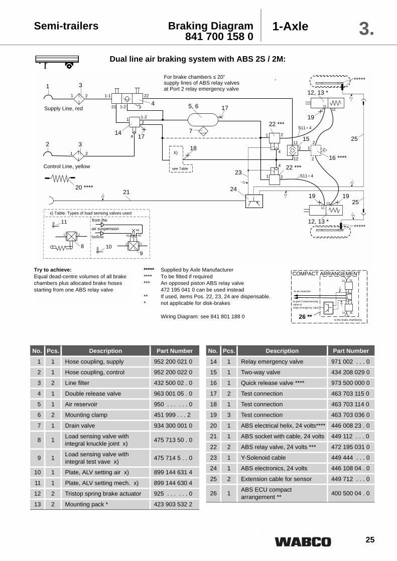
Semi-trailers Braking Diagram841 700 158 0
1-Axle 3.Dual line air braking system with ABS 2S / 2M:
No. Pcs. Description Part Number
1 1 Hose coupling, supply 952 200 021 0
2 1 Hose coupling, control 952 200 022 0
3 2 Line filter 432 500 02 . 0
4 1 Double release valve 963 001 05 . 0
5 1 Air reservoir 950 . . . . . . 0
6 2 Mounting clamp 451 999 . . . 2
7 1 Drain valve 934 300 001 0
8 1 Load sensing valve with integral knuckle joint x) 475 713 50 . 0
9 1 Load sensing valve withintegral test vave x) 475 714 5 . . 0
10 1 Plate, ALV setting air x) 899 144 631 4
11 1 Plate, ALV setting mech. x) 899 144 630 4
12 2 Tristop spring brake actuator 925 . . . . . . 0
13 2 Mounting pack * 423 903 532 2
No. Pcs. Description Part Number
14 1 Relay emergency valve 971 002 . . . 0
15 1 Two-way valve 434 208 029 0
16 1 Quick release valve **** 973 500 000 0
17 2 Test connection 463 703 115 0
18 1 Test connection 463 703 114 0
19 3 Test connection 463 703 036 0
20 1 ABS electrical helix, 24 volts**** 446 008 23 . 0
21 1 ABS socket with cable, 24 volts 449 112 . . . 0
22 2 ABS relay valve, 24 volts *** 472 195 031 0
23 1 Y-Solenoid cable 449 444 . . . 0
24 1 ABS electronics, 24 volts 446 108 04 . 0
25 2 Extension cable for sensor 449 712 . . . 0
26 1 ABS ECU compact arrangement ** 400 500 04 . 0
1
1
2
3
3
14
175, 6
7
21
1
22 ***
19
1
1-22
4
1 2
2
11
X)
see Table
12, 13 *
25
251
2
17
19
23
184
4
22 ***
24
89
43
41 42
21
21
10
11
214
1-2
22
3
19
1-1
2
12, 13 *
12
11
12
1112
2
16 ****
12
2
15
*****
*****
20 ****
xS11 4
xS11 4
x) Table: Types of load sensing valves used
from the
air suspension
bellow
For brake chambers ≤ 20“supply lines of ABS relay valves at Port 2 relay emergency valve
Supply Line, red
Control Line, yellow
***** Supplied by Axle Manufacturer**** To be fitted if required*** An opposed piston ABS relay valve
472 195 041 0 can be used instead** If used, items Pos. 22, 23, 24 are dispensable.* not applicable for disk-brakes
Wiring Diagram: see 841 801 188 0
Try to achieve:Equal dead-centre volumes of all brakechambers plus allocated brake hosesstarting from one ABS relay valve
22
1
23
4
to port 2 load-sensing valve orrelay emergency valve
to the brake chamber(s)
COMPACT ARRANGEMENT
to air reservoir
26 **

26
Dual line air braking system with ABS 4S / 2M
Braking Diagram Semi-trailers841 700 166 0
2-Axle3.
No. Pcs. Description Part Number1 1 Hose coupling, supply 952 200 021 0
2 1 Hose coupling, control 952 200 022 0
3 2 Line filter 432 500 02 . 0
4 1 Double release valve 963 001 05 . 0
5 1 Air reservoir 950 . . . . . . 0
6 2 Mounting clamp 451 999 . . . 2
7 1 Drain valve 934 300 001 0
8 1 Load sensing valve with integral knuckle joint x) 475 713 50 . 0
9 1 Load sensing valve withintegral test vave x) 475 714 5 . . 0
10 1 Plate, ALV setting air x) 899 144 631 4
11 1 Plate, ALV setting mech. x) 899 144 630 4
12 1 Link for ALV 433 401 004 0
13 4 Tristop spring brake actuator 925 . . . . . . 0
14 4 Mounting pack * 423 903 532 2
No. Pcs. Description Part Number15 1 Relay emergency valve 971 002 . . . 0
16 1 Two-way valve 434 208 029 0
17 1 Quick release valve **** 973 500 000 0
18 2 Test connection 463 703 115 0
19 1 Test connection 463 703 114 0
20 3 Test connection 463 703 036 0
21 1 ABS electrical helix, 24 volts*** 446 008 23 . 0
22 1 ABS socket with cable, 24 volts 449 112 . . . 0
23 2 ABS relay valve, 24 volts *** 472 195 031 0
24 1 Y-Solenoid cable 449 444 . . . 0
25 1 ABS electronics, 24 volts 446 108 04 . 0
26 2 Extension cable for sensor 449 712 . . . 0
27 2 Extension cable for sensor 449 712 . . . 0
28 1 ABS ECU compact arrangement ** 400 500 04 . 0
1
1
2
3
3
15
185, 6
7
22
1
23 ***
20
1
1-22
4
1 2
2
11
X)
see Table
13, 14 *
16 271
2
18
24
194
4
23 ***
25
89
43
41 42
21
21
10
11
214
1-2
22
3
1-1
2
12
11
12
2
11
13, 14 *
272012
11
13, 14 *
1211
13, 14 *
2012
26
26
12
21 ****
2
21
17 ****
***** *****
**********
xS11 4xS11 4
xS11 4
xS11 4
xS11 4
xS11 4
x) Table: Types of load sensing valves used
from the
air suspension
bellow
Supply Line, red
Control Line, yellow
***** Supplied by Axle Manufacturer**** To be fitted if required*** An opposed piston ABS relay valve
472 195 041 0 can be used instead** If used, items Pos. 23, 24, 25 are dispensable.* not applicable for disk-brakes
Wiring Diagram: see 841 801 188 0
Try to achieve:Equal dead-centre volumes of all brakechambers plus allocated brake hosesstarting from one ABS relay valve
22
1
23
4
to port 2 load-sensing valve orrelay emergency valve
to the brake chamber(s)
COMPACT ARRANGEMENT
to air reservoir
28 **

27
Semi-trailers Braking Diagram841 700 168 0
2-Axle 3.Dual line air braking system with ABS 4S / 3M
No. Pcs. Description Part Number
1 1 Hose coupling, supply 952 201 002 0
2 1 Hose coupling, control 952 201 001 0
3
4 1 Double release valve 963 001 05 . 0
5 1 Air reservoir 950 . . . . . . 0
6 2 Mounting clamp 451 999 . . . 2
7 1 Drain valve 934 300 001 0
8 1 Load sensing valve with integral knuckle joint x) 475 713 50 . 0
9 1 Load sensing valve withintegral test vave x) 475 714 5 . . 0
10 1 Plate, ALV setting air x) 899 144 631 4
11 1 Plate, ALV setting mech. x) 899 144 630 4
12 1 Link for ALV x) 433 401 004 0
13 4 Tristop spring brake actuator 925 . . . . . . 0
14 4 Mounting pack * 423 903 532 2
15 1 Relay emergency valve 971 002 . . . 0
No. Pcs. Description Part Number
16 1 Two-way valve 434 208 029 0
17 1 Adaptor valve **** 975 00 . 0 . . 0
18 1 Quick release valve **** 973 500 000 0
19 1 Test connection 463 703 115 0
20 1 Test connection 463 703 120 0
21 1 Test connection 463 703 . . . 0
22 4 Test connection 463 703 036 0
23 1 ABS electrical helix, 24volts **** 446 008 23 . 0
24 1 ABS socket with cable, 24 volts 449 112 . . . 0
25 3 ABS relay valve, 24 volts *** 472 195 031 0
26 1 Y-Solenoid cable 449 444 . . . 0
27 1 Solenoid cable 449 411 . . . 0
28 1 ABS electronics, 24 volts 446 108 03 . 0
29 2 Extension cable for sensor 449 712 . . . 0
30 2 Extension cable for sensor 449 712 . . . 0
31 1 ABS ECU compact arrangement ** 400 500 03 . 0
Supply Line, red
Control Line, yellow see Table
x) Table: Types of load sensing valves usedfrom the air suspension bellow
***** Supplied by Axle Manufacturer**** To be fitted if required*** An opposed piston ABS relay valve
472 195 041 0 can be used instead** If used, items Pos. 25, 26, 27, 28 are dispensable.* not applicable for disk-brakes
Wiring Diagram: see 841 801 188 0
Try to achieve:Equal dead-centre volumes of all brakechambers plus allocated brake hosesstarting from one ABS relay valve
22
1
23
4 2
4
21to port 2 load-sensing valve orrelay emergency valve
to the brake chamber(s)
COMPACT ARRANGEMENT
to air reservoir
31 **

28
Braking Diagram Semi-trailers841 700 466 0
3-Axle3.Dual line air braking system with ABS 4S / 2M
No. Pcs. Description Part Number1 1 Hose coupling, supply 952 200 021 0
2 1 Hose coupling, control 952 200 022 0
3 2 Line filter 432 500 02 . 0
4 1 Double release valve 963 001 05 . 0
5 1 Air reservoir 950 . . . . . . 0
6 2 Mounting clamp 451 999 . . . 2
7 1 Drain valve 934 300 001 0
8 1 Load sensing valve with integral knuckle joint x) 475 713 50 . 0
9 1 Load sensing valve withintegral test vave x) 475 714 5 . . 0
10 1 Plate, ALV setting air x) 899 144 631 4
11 1 Plate, ALV setting mech. x) 899 144 630 4
12 2 Brake Chamber 423 . . . . . . 0
13 2 Mounting pack 423 . . . 53 . 2
14 4 Tristop spring brake actuator 925 . . . . . . 0
No. Pcs. Description Part Number15 4 Mounting pack * 423 903 532 2
16 1 Relay emergency valve 971 002 . . . 0
17 1 Two-way valve 434 208 029 0
18 1 Quick release valve **** 973 500 000 0
19 2 Test connection 463 703 115 0
20 3 Test connection 463 703 114 0
21 1 Test connection 463 703 036 0
22 1 ABS electrical helix, 24volts **** 446 008 23 . 0
23 1 ABS socket with cable, 24 volts 449 112 . . . 0
24 3 ABS relay valve, 24 volts *** 472 195 031 0
25 1 Y-Solenoid cable 449 444 . . . 0
26 1 ABS electronics, 24 volts 446 108 04 . 0
27 2 Extension cable for sensor 449 712 . . . 0
28 2 Extension cable for sensor 449 712 . . . 0
29 1 ABS ECU compact arrangement ** 400 500 04 . 0
***** Supplied by Axle Manufacturer**** To be fitted if required*** An opposed piston ABS relay valve
472 195 041 0 can be used instead** If used, items Pos. 24, 25, 26 are dispensable.* not applicable for disk-brakes
Wiring Diagram: see 841 801 188 0
Try to achieve:Equal dead-centre volumes of all brakechambers plus allocated brake hosesstarting from one ABS relay valve
22
1
23
4
to port 2 load-sensing valve orrelay emergency valve
to the brake chamber(s)
COMPACT ARRANGEMENT
to air reservoir
29 **
1
1
2
3
316
195, 6
7
23
1
24 ***
21
1
1-22
4
1 2
2
11
X)
see Table
14, 15 *
18 ****28
1
2
19
25
204
4
24 ***
26
89
43
41 42
21
21
10
11
214
1-2
22
3
1-1
2
12
11
12
2
11
12, 13 *
282012
11
14, 15 *
1211
12, 13 *
2012
27
27
14, 15 *
14, 15 *
1
2
2
17
***** *****
**********
22 ****
xS11 4 xS11 4
xS11 4
xS11 4
x) Table: Types of load sensing valves used
from the
air suspension
bellow
Supply Line, red
Control Line, yellow

29
Semi-trailers Braking Diagram841 700 464 0
3-Axle 3.Dual line air braking system with ABS 4S / 3M
No. Pcs. Description Part Number
1 1 Hose coupling, supply 952 200 021 0
2 1 Hose coupling, control 952 200 022 0
3 2 Line filter 432 500 02 . 0
4 1 Double release valve 963 001 05 . 0
5 1 Air reservoir 950 . . . . . . 0
6 2 Mounting clamp 451 999 . . . 2
7 1 Drain valve 934 300 001 0
8 1 Load sensing valve with integral knuckle joint x) 475 713 50 . 0
9 1 Load sensing valve withintegral test vave x) 475 714 5 . . 0
10 1 Plate, ALV setting air x) 899 144 631 4
11 1 Plate, ALV setting mech. x) 899 144 630 4
12 2 Brake Chamber 423 . . . . . . 0
13 2 Mounting pack 423 . . . 53 . 2
14 4 Tristop spring brake actuator 925 . . . . . . 0
15 4 Mounting pack * 423 903 532 2
16 1 Relay emergency valve 971 002 . . . 0
No. Pcs. Description Part Number17 1 Two-way valve 434 208 029 0
18 1 Quick release valve **** 973 500 000 0
19 1 Adaptor valve 975 00 . 0 . . 0
20 2 Test connection 463 703 115 0
21 3 Test connection 463 703 114 0
22 1 Test connection 463 703 036 0
23 1 Test connection 463 703 . . . 0
24 1 ABS electrical helix, 24volts **** 446 008 23 . 0
25 1 ABS socket with cable, 24 volts 449 112 . . . 0
26 3 ABS relay valve, 24 volts *** 472 195 031 0
27 1 Y-Solenoid cable 449 444 . . . 0
28 1 Solenoid cable 449 411 . . . 0
29 1 ABS electronics, 24 volts 446 108 03 . 0
30 2 Extension cable for sensor 449 712 . . . 0
31 2 Extension cable for sensor 449 712 . . . 0
32 1 ABS ECU compact arrangement ** 400 500 03 . 0
***** Supplied by Axle Manufacturer**** To be fitted if required*** An opposed piston ABS relay valve
472 195 041 0 can be used instead** If used, items Pos. 26, 27, 28, 29 are dispensable.* not applicable for disk-brakes
Wiring Diagram: see 841 801 188 0
Try to achieve:Equal dead-centre volumes of all brakechambers plus allocated brake hosesstarting from one ABS relay valve
1
1
2
3
316
235, 6
7
25
1
26 ***
22
1
1-22
4
1 2
2
11
X)
see Table
14, 15 *
18 ****31
1
2
20
27
21 4
4
26 ***
29
89
43
41 42
21
21
10
11
214
1-2
22
3
1-1
2
12
11
12
2
11
12, 13 *
3121
12
11
14, 15 *
1211
12, 13 *
21 12
30
30
14, 15 *
14, 15 *
12
217
***** *****
**********
24 ****
xS11 4
xS11 4
xS11 4xS11 4
26 ***1
4
2
19 ****
22
1 2
28
x) Table: Types of load sensing valves used
from the
air suspension
bellow
Supply Line, red
Control Line, yellow
22
1
23
4 2
4
21to port 2 load-sensing valve orrelay emergency valve
to the brake chamber(s)
COMPACT ARRANGEMENT
to air reservoir
32 **
30
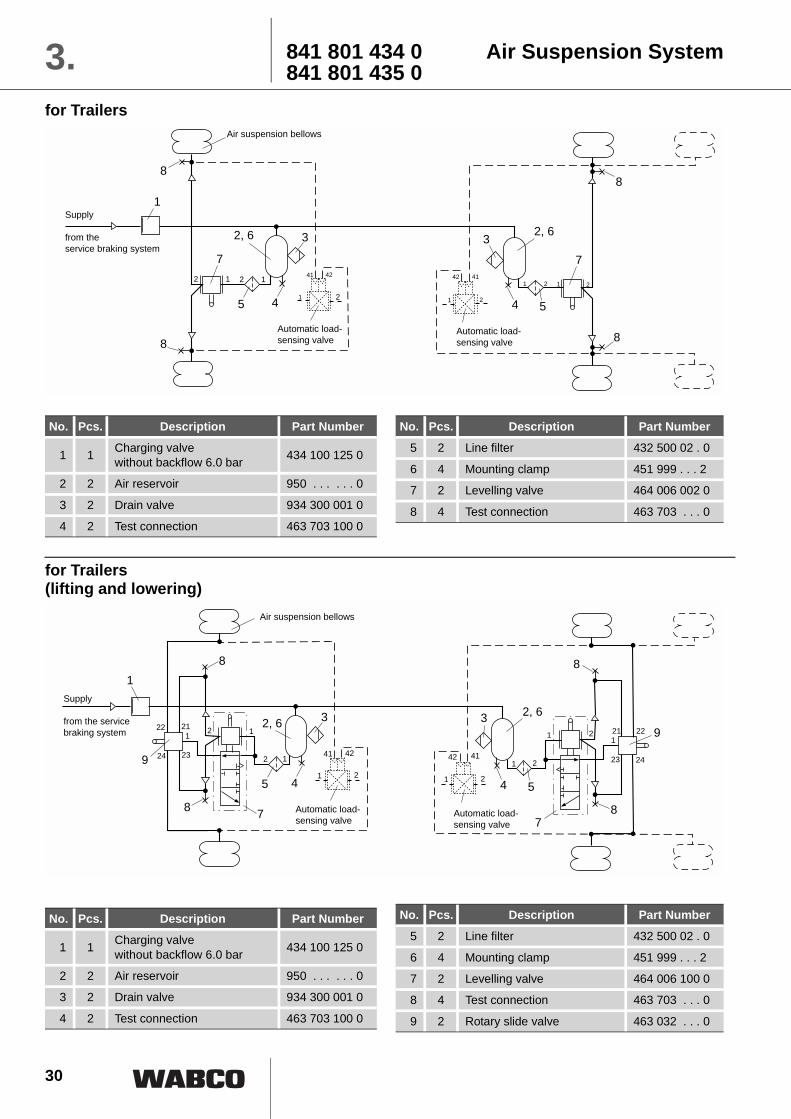
841 801 434 0 Air Suspension System841 801 435 03.
for Trailers
No. Pcs. Description Part Number
1 1 Charging valve without backflow 6.0 bar 434 100 125 0
2 2 Air reservoir 950 . . . . . . 0
3 2 Drain valve 934 300 001 0
4 2 Test connection 463 703 100 0
No. Pcs. Description Part Number5 2 Line filter 432 500 02 . 0
6 4 Mounting clamp 451 999 . . . 2
7 2 Levelling valve 464 006 002 0
8 4 Test connection 463 703 . . . 0
No. Pcs. Description Part Number
1 1 Charging valve without backflow 6.0 bar 434 100 125 0
2 2 Air reservoir 950 . . . . . . 0
3 2 Drain valve 934 300 001 0
4 2 Test connection 463 703 100 0
No. Pcs. Description Part Number5 2 Line filter 432 500 02 . 0
6 4 Mounting clamp 451 999 . . . 2
7 2 Levelling valve 464 006 100 0
8 4 Test connection 463 703 . . . 0
9 2 Rotary slide valve 463 032 . . . 0
for Trailers(lifting and lowering)
5
2, 6
7
12 4142
21
Automatic load-sensing valve
41 42
1
Supply
from theservice braking system
2, 6
12
4
3
8
1
88
5
7
4
3
8
Air suspension bellows
2
2 211
Automatic load-sensing valve
5
2, 6
7
1241 42
2, 6
12
4
3
8
1
8
9
54
3
8
21
4142
21
1 2
7
8
22 21
24 23
12221
2423
1
21
9
Automatic load-sensing valve
Supply
from the service braking system
Air suspension bellows
Automatic load-sensing valve

31
Air Suspension System 841 801 436 0841 801 437 0 3.
for Semi-trailer
No. St. Description Part Number5 1 Drain valve 934 300 001 0
6 1 Test connection 463 703 100 0
7 2 Levelling valve 464 006 002 0
8 2 Test connection 463 703 . . . 0
No. Pcs. Description Part Number
1 1 Charging valve without backflow 6.0 bar 434 100 125 0
2 1 Air reservoir 950 . . . . . . 0
3 2 Mounting clamp 451 999 . . . 2
4 1 Line filter 432 500 02 . 0
No. Pcs. Description Part Number
5 1 Drain valve 934 300 001 0
6 1 Test connection 463 703 100 0
7 1 Levelling valve 464 006 100 0
8 2 Test connection 463 703 . . . 0
9 1 Rotary slide valve 463 032 . . . 0
for Semi-trailer(lifting and lowering)
No. Pcs. Description Part Number
1 1 Charging valve without backflow 6.0 bar 434 100 125 0
2 1 Air reservoir 950 . . . . . . 0
3 2 Mounting clamp 451 999 . . . 2
4 1 Line filter 432 500 02 . 0
2, 34142
21
64
1
8
5
7
8
Automatic load-sensing valve
Supply
from theservice braking system
Air suspension bellows
2, 3 41 42
21
64
1
5
8
1 2
7
8
2221
2423
191 2
Automatic load-sensing valve
Supply
from theservice braking system
Air suspension bellows

32
841 801 447 0 Lift Axle System841 801 448 03.
Lift Axle Control Valve solenoid raise / automatic lower
No. Pcs. Description Part Number
6 1 Pressure limiting valve 475 010 . . . 0
7 1 Pressure switch 441 042 000 0
8 1 Test connection 463 703 100 0
9 1 Switch
10 1 Levelling valve 464 006 . . . 0
No. Pcs. Description Part Number1 1 Charging valve 434 100 125 0
2 1 Air reservoir 950 . . . . . . 0
3 1 Line filter 432 500 020 0
4 1 Air reservoir 950 410 004 0
No. Pcs. Description Part Number5 1 Lift axle control valve 463 084 000 0
6 1 Pressure limiting valve 475 010 . . . 0
7 2 Pressure limiting valve 463 703 100 0
8 1 Levelling valve 464 006 . . . 0
Lift Axle Control Valve solenoid raise / automatic lower
No. Pcs. Description Part Number
1 1 Charging valve 434 100 125 0
2 1 Air reservoir 950 . . . . . . 0
3 1 Line filter 432 500 020 0
4 1 Air reservoir 950 410 004 0
5 1 Lift axle control valve 463 084 010 0
2
Lift bellows
3
6
1 8
Suspensionbellows
4
5
7
323
10
1 2
24
20
1 2
9
+II
I
22 21 1 42
41
* *
* * optional
Plastic pipe 12 x 1,5Alternative 10 x 1
Tes
t val
ve 12
23
6
1
4
5
7
323
8
1 2
24
20
1 2
II
I
22 21 1 4241
* *
* * optional
12
Lift bellows
Suspensionbellows
Plastic pipe 12 x 1,5Alternative 10 x 1
Tes
t val
ve

33
Lift Axle System 841 801 449 0841 801 479 0 3.
23
6
1
4
5
7
323
8
1 2
24
20
1 2
22 21 1 4241
* *
* * optional
12
9
10
2 1
Lift bellows
Suspensionbellows
Plastic pipe 12 x 1,5Alternative 10 x 1
Tes
t val
veFully automatic raise and lower with 3/2- directional control valve
No. Pcs. Description Part Number
1 1 Charging valve 434 100 125 0
2 1 Air reservoir 950 . . . . . . 0
3 1 Line filter 432 500 020 0
4 1 Air reservoir 950 410 004 0
5 1 Lift axle control valve 463 084 020 0
No. Pcs. Description Part Number
6 1 Pressure limiting valve 475 010 . . . 0
7 2 Test connection 463 703 100 0
8 1 Levelling valve 464 006 . . . 0
9 1 3/2 Directional control valve 463 036 016 0
10 1 Throttle Ø 1,5 mm . . . . . . . . . .
No. Pcs. Description Part Number1 1 Charging valve 434 100 125 0
2 1 Air reservoir 950 . . . . . . 0
3 1 Line filter 432 500 020 0
4 1 Air reservoir 950 410 004 0
No. Pcs. Description Part Number6 1 Lift axle control valve 463 084 020 0
7 1 Pressure limiting valve 475 010 . . . 0
8 2 Test connection 463 703 100 0
9 1 Levelling valve 464 006 . . . 0
Fully automatic raise and lower
23
6
1
4
5
7
323
8
1 2
24
20
1 2
22 21 1 4241
* *
* * optional
12
Lift bellows
Suspensionbellows
Plastic pipe 12 x 1,5Alternative 10 x 1
Tes
t val
ve

34
841 801 923 0 Lifting axle control EBS D3.Full automatic with traction help and single circuit lifting axle valve and residual pressurecontrol
switching to plus
switching to minus
Lifting axle circuit T - EBS DButton traction help:press less than 5 sec. = start traction helppress > 5 sec. = constrained lowering
Control independend from truck
Pay attention to parametersplease consider ISO 12098 wiringplease consider truck wiring
* optional
Plastic pipe 12 x 1.5or 10 x 1
Lift bellows
Suspension bellows
from theservice braking system
not be connected
brown GND
black - Input
1 = N. C.2 = GND3 = Signal / Eingang
Diagnosis
No. Pcs. Description Part Number
1 1 Charging valve with backflow 434 100 026 0
2 1 Pressure limiting valve 475 010 . . . 0
3 1 Lifting axle valve 463 084 030 0
4 1 Raise/Lower valve 463 032 020 0
5 1 Levelling valve 464 006 100 0
6 1 Charging valve without backflow 434 100 125 0
No. Pcs. Description Part Number
7 1 Air reservoir 950 . . . . . . 0
8 1 Trailer modulator 480 102 01 . 0
9 2 Diode (eg. Wehrle)
10 1 Cable 449 764 . . . 0
11 1 Diagn. + ISS / ILS-cable 449 664 000 0
12 1 2/2-Way Solenoid valve 472 175 426 0

35
Description of Components
4.
2

36
Overview4.
2
pageBrake Chamber 423 000 37Line Filter 432 500 45Knuckle Joint 433 306 46Linkage for Levelling Valve 433 401 48Check - Valve 434 014 49Charging Valve 434 100 50Two-Way Valve 434 208 52Pressure Switch 441 009 / 042 54Accessories for Hose Couplings 452 000 57Shut-Off Cock 452 002 58Duo-Matic Quick Coupling 452 80 . 59Raise/Lower Valve 463 032 63Release Valve 463 034 663/2-Directional Control Valve 463 036 67Lift Axle Control Valve 463 084 68Test Coupling 463 703 75Levelling Valve 464 006 773/2-Way Solenoid Valve 472 102 / 171 / 173 823/2-Way Solenoid Valve 472 127 / 170 / 172 84Pressure Reducing Valve 473 301 86Quick Release Valve 473 501 88Pressure Limiting Valve 475 010 90Outline Load-Sensing Valves for Trailers 475 . . . 92Load-Sensing Relay Emergency Valve 475 712 94Load-Sensing Valve (ALV) 475 713 98Load-Sensing Valve (ALV) 475 714 102Load-Sensing Relay Emergency Valve 475 715 108Indicator Plate ”Load Sensing Device Settings“ 899 144 115”PC Service“ for Settings of the Load-Sensing Device 116Load-Sensing Valve 475 800 117Tristop Spring Brake Actuator 925 3 . . / 4 . . 120Drain Valve 934 300 129Air Reservoir 950 000 130Hose Coupling 952 200 / 201 132Release Valve 963 001 / 006 137Height Limiting Valve 964 001 141Relay Emergency Valve 971 002 143Relay Valve 973 001 / 011 156Quick Release Valve 973 500 161Adapter Valve 975 001 163Adapter Valve 975 002 166

37
Purpose:To generate the braking force for thewheel brakes. It can also be used forother purposes, e. g. clamping, liftingand actuating.
Operation:When the pressure from port (A) or(B) acts upon diaphragm (b), the di-aphragm and piston (a) move to theright. The resulting piston force istransmitted through push rod (c) tothe brake lever (slack adjuster) andthen to the wheel brakes.
When the actuator is exhausted,spring (d) causes piston (a) and dia-phragm (b) to return to theirunapplied position.
The diaphragm actuator force de-pends on the diaphragm loadpressure and on the effective dia-phragm surface area which varieswith the amount of curvature in thediaphragm (b).
Maintenance:No maintenance is necessary be-yond the tests required by law.However, even if working satisfacto-rily (no leakages, response pressurenot exceeding 0.5 bar), the brakechamber should be removed, disas-sembled, cleaned, wearing partsreplaced, and then reassembled atleast every two years.
Brake Chamber 423 000 4.
for Disc Brake

38
The diaphragm should be installedwith the link joint slantingdownwards so that any water that issplashed into the unit can drain out.
When installing the brake chamber,care should be taken that the brakeline is not positioned lower than theactuator unit. This prevents damageto the brake line caused by groundscraping. To facilitate correct lineinstallation, the diaphragm actuatoris provided with two connectingports, either of which can be used byrepositioning the screw plug.
When installing the actuator or whenadjusting the brakes, the push rodmust not be pulled out. In the
unapplied position, the spring in theunit must push the piston and thediaphragm against the housing (seeinstallation schematic).
It is also important that the push rodis not pulled out when actuating amechanical parking braking systemwhich is also connected to the brakelever since this could cause damageto the actuator parts. One way toprevent the push rod being pulledout is to use the diaphragm actuatorwith a slotted link joint rather thanwith a roundhole link joint. This pro-vides the equivalent of at least a two-thirds maximum diaphragm actuatorstroke for separate actuation of theparking braking system.
Brake Chamber423 0004.
2
Note: If the brake chamber is fitted vertical-ly on steering dummy axles (pistonrod pointing upwards), the sealedversion is recommended by axlemanufacturers:
Installation schematic:
Sections 2 and 3 also apply (fittingand mounting) of the installationinstructions for Tristop spring brakeactuators, see Page 123.
*) can be supplied by the axle manufacturer.
Installation Requirements:
Operating positionat one half of maximum
Unapplied positionmust have no clearancebetween piston and diaphragm
Part Number20" 423 105 905 0 } with Mounting Kit24" 423 106 905 0
16" 423 104 906 0 without Mounting Kit
39
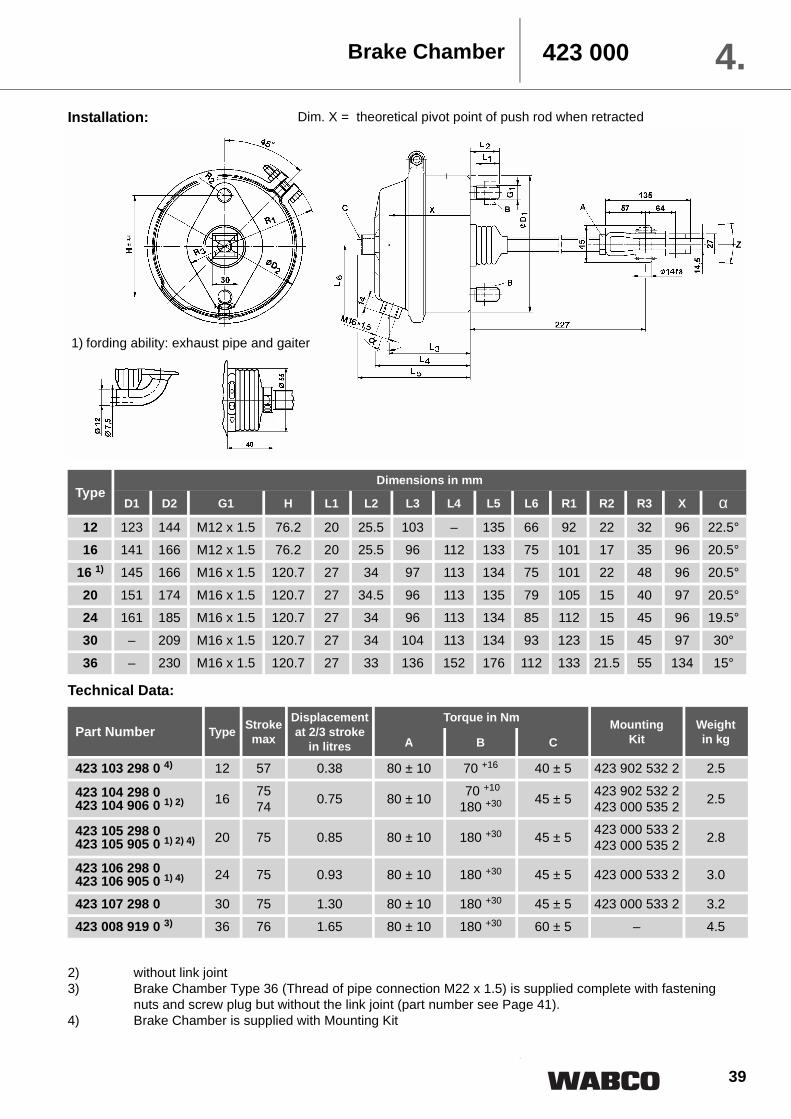
1) fording ability: exhaust pipe and gaiter
Dim. X = theoretical pivot point of push rod when retracted
Brake Chamber 423 000 4.
TypeDimensions in mm
D1 D2 G1 H L1 L2 L3 L4 L5 L6 R1 R2 R3 X α12 123 144 M12 x 1.5 76.2 20 25.5 103 – 135 66 92 22 32 96 22.5°16 141 166 M12 x 1.5 76.2 20 25.5 96 112 133 75 101 17 35 96 20.5°
16 1) 145 166 M16 x 1.5 120.7 27 34 97 113 134 75 101 22 48 96 20.5°
20 151 174 M16 x 1.5 120.7 27 34.5 96 113 135 79 105 15 40 97 20.5°24 161 185 M16 x 1.5 120.7 27 34 96 113 134 85 112 15 45 96 19.5°
30 – 209 M16 x 1.5 120.7 27 34 104 113 134 93 123 15 45 97 30°
36 – 230 M16 x 1.5 120.7 27 33 136 152 176 112 133 21.5 55 134 15°
Technical Data:
Part Number Type Strokemax
Displacementat 2/3 stroke
in litres
Torque in Nm MountingKit
Weightin kgA B C
423 103 298 0 4) 12 57 0.38 80 ± 10 70 +16 40 ± 5 423 902 532 2 2.5
423 104 298 0423 104 906 0 1) 2) 16 75
74 0.75 80 ± 10 70 +10
180 +30 45 ± 5 423 902 532 2423 000 535 2 2.5
423 105 298 0 423 105 905 0 1) 2) 4) 20 75 0.85 80 ± 10 180 +30 45 ± 5 423 000 533 2
423 000 535 2 2.8
423 106 298 0 423 106 905 0 1) 4) 24 75 0.93 80 ± 10 180 +30 45 ± 5 423 000 533 2 3.0
423 107 298 0 30 75 1.30 80 ± 10 180 +30 45 ± 5 423 000 533 2 3.2
423 008 919 0 3) 36 76 1.65 80 ± 10 180 +30 60 ± 5 – 4.5
Installation:
2) without link joint3) Brake Chamber Type 36 (Thread of pipe connection M22 x 1.5) is supplied complete with fastening
nuts and screw plug but without the link joint (part number see Page 41).4) Brake Chamber is supplied with Mounting Kit
40
Brake Chamber423 0004.
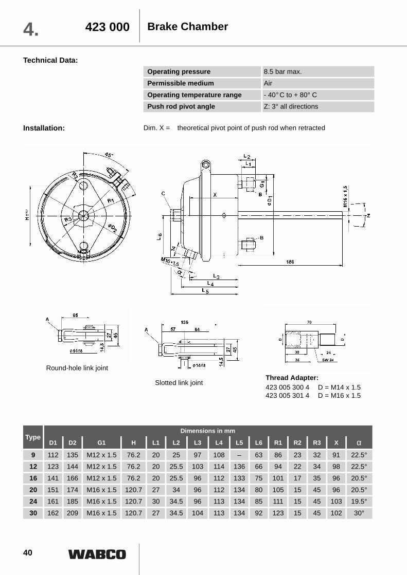
Installation:
Operating pressure 8.5 bar max.
Permissible medium Air
Operating temperature range - 40��C to + 80° CPush rod pivot angle Z: 3° all directions
Dim. X = theoretical pivot point of push rod when retracted
Technical Data:
TypeDimensions in mm
D1 D2 G1 H L1 L2 L3 L4 L5 L6 R1 R2 R3 X α9 112 135 M12 x 1.5 76.2 20 25 97 108 – 63 86 23 32 91 22.5°12 123 144 M12 x 1.5 76.2 20 25.5 103 114 136 66 94 22 34 98 22.5°
16 141 166 M12 x 1.5 76.2 20 25.5 96 112 133 75 101 17 35 96 20.5°
20 151 174 M16 x 1.5 120.7 27 34 96 112 134 80 105 15 45 96 20.5°24 161 185 M16 x 1.5 120.7 30 34.5 96 113 134 85 111 15 45 103 19.5°
30 162 209 M16 x 1.5 120.7 27 34.5 104 113 134 92 123 15 45 102 30°
Slotted link joint
Round-hole link jointThread Adapter:423 005 300 4 D = M14 x 1.5423 005 301 4 D = M16 x 1.5

41
Brake Chamber 423 000 4.Technical Data:
* with bellows
Part Number Type Strokemax
Displacementat 2/3 stroke
in litres
Torque in Nm Part Number for Mounting Kit Weightin kgA B C Round-hole Slotted
423 102 900 0 * 9 60 0.28 80 ± 10 70 +16 – 423 902 537 2 423 902 536 2 2.5
423 103 900 0 * 12 60 0.40 80 ± 10 70 +16 40 ± 5 423 902 533 2 423 902 534 2 2.5
423 104 900 0 16 75 0.75 80 ± 10 70 +16 45 ± 5 423 902 533 2 423 902 534 2 2.5423 105 900 0 20 75 0.85 80 ± 10 180 +30 45 ± 5 423 000 534 2 423 000 535 2 2.8
423 106 900 0 24 75 0.93 80 ± 10 180 +30 45 ± 5 423 000 534 2 423 000 535 2 3.0
423 107 900 0 30 75 1.15 80 ± 10 180 +30 45 ± 5 423 000 534 2 423 000 535 2 3.2
The following mounting kits areavailable on request:
Mounting Kit for Brake Chamber:
No. Description Part Number
Part Number: Mounting Kit
423
000
531
2
423
000
532
2
423
000
533
2
423
000
534
2
423
000
535
2
423
002
530
2
423
103
532
2
423
901
533
2
423
901
538
2
423
902
532
2
423
902
533
2
423
902
534
2
423
902
535
2
423
902
536
2
423
902
537
2
423
903
530
2
1 Screw Plug M16 x 1.5 893 011 710 4 1 1 1 1 1 1 1 1 12 Packing A16 x 20 811 401 057 4 1 1 1 1 1 1 1 1 1
3 Hexagon NutM12 810 304 026 4 2 2 2 2M12 x 1.5 810 304 027 4 2 2 2 2 2 2M16 x 1.5 810 304 031 4 2 2 2 2 2
4 Hexagon NutM14 x 1.5 810 306 013 4 1 1 1M16 x 1.5 810 319 029 4 1 1 1 1 1 1 1 1
5 Link Joint withBolt Ø 14
M16 x 1.5 895 801 310 2 1 1 1 1M14 x 1.5 895 801 312 2 1 1
6 Link Joint withBolt Ø 14
M16 x 1.5 895 801 513 2 1 1 1 1M14 x 1.5 895 801 511 2 1M14 x 1.5 810 612 020 2
– Bolt14 x 45 x 35.6 810 601 100 4 1 1 114 x 45 x 31.2 810 601 097 4 112 x 45 x 34 810 601 084 4 1
– Disk 15 810 403 011 4 2 2 2– Splint 4 x 22 810 511 034 4 2 2 2 2 2

42
Characteristics of Brake Chambers Types 9 to 30
ThA = medium piston force: This is the piston force whichis established through an in-tegration of between 1/3 and2/3 of total piston stroke(smax).
sp = usable piston stroke: This is the stroke at whichpiston force Th is 90% of me-dium piston force ThA.
Type ThA (N) = sp (mm) smax (mm)
9 606 x p -242 0.64 x p +44 6012 766 x p -230 0.57 x p + 46 60
16 1056 x p - 317 0.86 x p + 68 75
20 1218 x p - 244 0.74 x p + 69 7524 1426 x p - 285 0.56 x p + 70 75
30 1944 x p - 389 0.67 x p + 62 75
Brake Chamber423 0004.
16
14
12
10
8
6
4
2
0 1 2 3 4 5 6 7 8
401 2 3 4 5 6 7 8
80
60
0
Input pressure in bar
Type
Med
ium
pis
ton
fo
rce
Th
A in
kN
Usa
ble
pis
ton
str
oke
Sp in
mm
24201630
129
30
20
16
12
9
24
Input pressure in bar

43
Installation:
Brake Chamber for disk brakes 423 000 4.
2
1) with screw plug M16 x 1.5 2) 57 mm Stroke permissible installation position
Part Number TypeDimensions in mm Port
D1 D2 L1 L2 L3 L4 L5 R1 a A B
423 114 710 0 14 146 166 98 95 67 106 121 101 20° x 1)423 104 710 0 16 146 166 98 95 67 106 121 101 20° x x
423 104 715 0 16 146 166 98 92 64 102 117 101 0° 1) x
423 104 716 0 16 146 166 98 92 64 102 117 101 90° 1) x423 112 710 0 18 153 175 94 92 65 103 117 106 20° x x
423 505 000 0 20 153 175 94 92 65 102 117 106 20° x x
423 110 710 0 22 163 185 94 92 65 102 117 111 20° x x423 506 001 0 24 163 185 94 92 65 102 117 111 20° x x
423 506 002 0 2) 24 163 185 94 92 65 102 117 111 90° 1) x
Technical Data:
Type Deflection of the push rod
Strokemax.
Displacement at 2/3 stroke in litres
[at 6 bar]
Operating pressure
max.
Operating temperature range
Weightin kg
14
max. 8° at 0 mm Stroke
57 mm 0.60 10 bar
- 40°C bis + 80°C
3.216 57 mm 0.60 10 bar 3.2
18 62 mm 0.68 10 bar 2.8
20 62 mm 0.71 10.2 bar 2.822 62 mm 0.81 10.2 bar 3.0
24 62 mm 0.81 10.2 bar 3.0
permissible installation position + 60°- 10°
in mounted positionlower breather hole ± 30°
** out of plane
Stroke

44
Fitting instruction for disk brake cylinders for trailers
1 The cylinder must be fitted hori-zontal Permissible deviation: 10° with push rod showing up-ward and 30° showing down-wards.
2. The open drain/breather holemust point downwards. Max de-viation +/- 30° It is essential toremove the plastic plug.
3. With tristop cylinders, the theconnecting line between servicebrake and spring box must be fit-ted in the area of the cylinder'supper part.
4. FasteningTo fix the cylinders, use nuts M16x1.5 property class 8 (WABCONr. 810 304 031 4). Tighten both nuts by hand untilCylinder has plane contact. Tigh-ten both nuts with 120 N.Tighten both nuts with torquekey to 210 Nm (tolerance30Nm). Using self-securing nuts,the torque must be raised appro-priately
5. The push rod must join the flatte-ned dome of the brake lever.
6. Flange area and sealing surfaceof cylinder and disk brake mustbe clean and undamaged. Thegaiter must have no damagesand together wit the back-up ring,being proper seated.
7. After fitting the tristop cylinder,the release screw must be scre-wed to the driving position (tor-que with 25 + 20 Nm).
Brake Chamber for disk brakes423 0004.
2
Test results for brake cylinderfor disk brakes type 14 to 24
ThA = medium piston force: This is the piston force whichis established through an in-tegration of between 1/3 and2/3 of total piston stroke(smax).
sp = usable piston stroke: This is the stroke at whichpiston force Th is 90% of me-dium piston force ThA.
Typ ThA (N) = sp (mm) smax (mm)
14 861p -255 1.40p +40 5716 1062p -308 0.54p + 46 57
18 1138p - 330 1.19p + 47 64
20 1210p - 351 1.00p + 55 6422 1332p - 373 0.79p + 50 64
24 1453p - 407 0.57p + 48 64

45
Purpose:To protect the air braking systemagainst dirt.
Operation:The compressed air reaching theline filter via port 1 passes throughthe filter cartridge in which any parti-cles of dirt are retained; thecompressed air is cleaned before itreaches any downstream appliancesfrom port 2.
If the line filter is blocked, the filtercartridge is pushed upwards againstthe force of the pressure spring andthe compressed air will pass throughthe line filter without being cleaned.If port 1 is exhausted while the filtercartridge is blocked, the pressure inport 2 can push the cartridge down-wards against the force of the
compression spring. This permits re-turn flow from port 2 to port 1.
Maintenance:
The frequency for cleaning the filterdepends largely on the operatingconditions and is normally approx.every 3 to 4 months. Remove the fil-ter cartridge and blow through withcompressed air. Damaged filter car-tridges need to be replaced.
Installation Requirements:
The filter is placed in the piping sys-tem without being fastened. Makesure that there is sufficient space forremoving the filter cartridge (see”Installation“).
Technical Data: Part Number 432 500 020 0 432 500 021 0Operating pressure 20 bar max.
Free passage Ø 12 mm = 1.13cm2
Thread of pipe connections G = M22 x 1.5 G = M16 x 1.5
Pore size of Filter 80 to 140 µm
Permissible medium AirOperating temperature range - 40��C to + 80° C
Weight 0.29 kg
Installation:
Line Filter 432 500 4.
Port connections:1 = Energy supply2 = Energy delivery
*) Space required for removing filter cartridge

46
the point which is not subject to anyinfluence from either:
1. Torsional movement of the axleduring the braking process, or
2. Drifting in bends in the case ofsteerable axle units, or
3. One-sided axle load due to uneven road surfaces.
Proper positioning of the knucklejoint ensures that only changes inthe axle load (both static and dynam-ic) will effect adjustment of theautomatic load-sensing valve.
The knuckle joint is connected to thecontrol lever of the automatic loadsensing valve by means of a rod (M8thread) and a hex nut (M8, DIN 934),neither of which are included in thepack. The length of this rod dependson the individual installation of theappliances in the vehicle.
Depending on the existing connec-tion for the connecting rod on thecontrol lever of the automatic loadsensing valve to be used, the con-necting rod is left smooth or
Knuckle Joint433 3064.Purpose:
To prevent damage to the automaticload sensing valve.
Operation:
In the event of large axle movementsin excess of the range of movementof the automatic load sensing valve,arm (e), which is horizontal while atrest, is deflected about a fixed pointin housing (c). Pressure springs (a)and (b) exert pressure on ball (d)providing constant tensional contactwith housing (c) until arm (e) againreturns to its normal horizontal posi-tion where it is again in full contactwith the front face of the housing.
Deformation of the connecting link-age to the automatic load sensingvalve is prevented by a ball joint (f)attached to arm (e).
Maintenance:No special maintenance is neces-sary beyond the legal requirements.
Installation Requirements:The selected knuckle joint must besuch that any travel exceeding theoperating range of the load-sensingvalve is no greater than the permis-sible deflection (h).
Deflection values for single and tan-dem trailer axles are shown in thegraph below:
The knuckle joint is mounted on thesingle axle or between the axles ofthe tandem axle unit, taking care tofollow the axle manufacturer's spec-ifications. The knuckle joint isarranged in such a way that its balljoint is located at the ”neutral point“of the axle(s). The ”neutral point“ is
fmax = maximum spring deflection in accordance with axle manufacturer's specifications

47
threaded (M8) for a total length ofapprox. 25 mm. This thread takes ahexagon nut M9 DIN 934. The otherend is screwed into the ball joint andsecured by means of the hexagon
nut. In order to prevent damage tothe flexible rubber connections, thesmooth ends need to be carefullydeburred.
Installation:
Technical Data:Part Number Length L
in mmDeflection h
in mmDeflection force in N
F1 F2433 306 002 0 260 100 90 190
Knuckle Joint 433 306 4.
48
Installation:
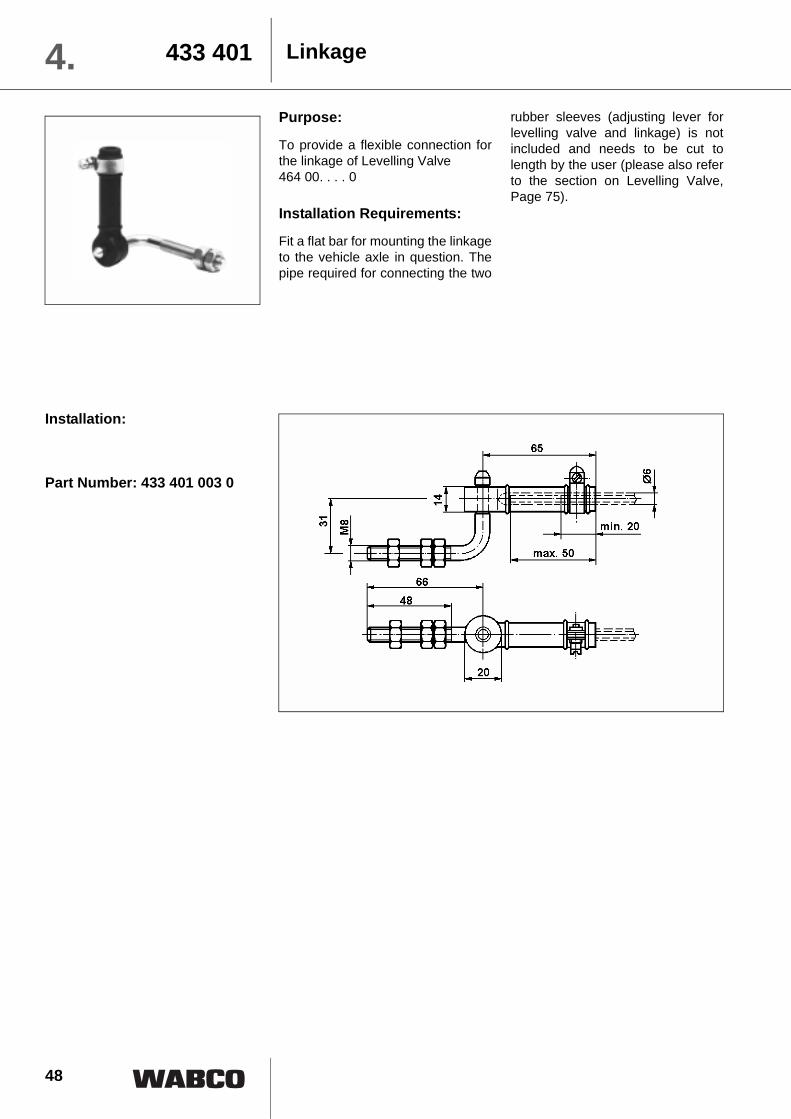
Part Number: 433 401 003 0
Linkage433 4014.Purpose:
To provide a flexible connection forthe linkage of Levelling Valve 464 00. . . . 0
Installation Requirements:
Fit a flat bar for mounting the linkageto the vehicle axle in question. Thepipe required for connecting the two
rubber sleeves (adjusting lever forlevelling valve and linkage) is notincluded and needs to be cut tolength by the user (please also referto the section on Levelling Valve,Page 75).

49
Purpose:
To protect the pressurized linesagainst unintentional venting.
Operation:
Air can only pass in the direction in-dicated by the arrow. Return flow ofthe air is prevented by the checkvalve closing the inlet in the event ofa drop in pressure in the supply line.
When the pressure rises in the sup-ply line, the springloaded checkvalve again opens the passagewhich results in an equalization ofpressure.
Maintenance:
No special maintenance is neces-sary beyond the legal requirements.
Installation Requirements:
The Check Valve can be fitted in anyposition within the piping system.Look out for the arrow on the hous-ing which indicates the direction ofair flow.
Technical Data:
Installation:
Check - Valve 434 014 4.
2
Symbol A
Symbol B
Operating pressure 20 bar max.
Nominal diameter Ø 8 mm
Thread of pipe connections M22 x 1.5Permissible medium Air
Operating temperature range - 40��C to + 80° C
Weight 0.17 kg
Part Number Symbol Comments434 014 000 0 A
434 014 001 0 B constant throtting Ø 1 mm
434 014 013 0 B constant throtting Ø 0.5 mm

50
Charging Valve434 1004.
2
Purpose:Charging Valve with return flow The passing of compressed air tosecond air brake reservoir only whenthe rated pressure for the system inthe first reservoir has been reached.If the pressure in the first reservoirfalls below that of the second reser-voir there is a feedback supply of airfrom the second reservoir.
Charging Valve without returnflowThe passing of compressed air toauxiliary equipment (e. g. door actu-ation, auxiliary and parking brakingsystems, servo clutch, etc.) onlywhen the rated pressure for thebraking system has been reached inevery air reservoir.
Charging Valve with limited returnflow The passing of compressed air toother consumers (e. g. auxiliary andparking braking systems) only whenthe rated pressure for the brakingsystem has been reached in all res-ervoirs. Also the protection ofpressure for the motor vehicle in theevent of the trailer's supply line fail-ing.If the pressure in the air reservoirs ofthe service braking system drops,part of the compressed air will returnuntil the closing pressure (which isdependent on the opening pressure)is reached
Operation:With all charging valves, the com-pressed air passes in the direction ofthe arrow into the housing andthrough port (g) under diaphragm (d)which is pressed into its seat by ad-justing spring (b) and piston (c).When the charging pressure hasbeen reached, the force of the ad-justing spring (b) is overcome so thatthe diaphragm (d) is lifted from its
seat, opening port (e). The air flowsdirectly or after opening of non-re-turn valve (h) to the reservoirs orconsumers in the direction of thearrow.
Charging valves with return flow al-low the compressed air to flow backfrom the second reservoir after theopening of check valve (f) if the pres-sure in the first reservoir hasdropped by more than 0.1 bar.In the case of charging valves with-out return flow, return flow is notpossible since non-return valve (h) iskept closed by the higher pressure inthe second reservoir.
Charging valves with limited returnflow allow the air to flow back untilthe closing pressure of diaphragm(d) is reached. When this is reached,adjusting spring (b) presses dia-phragm (d) into its seat via piston (c),thus preventing any further pressurecompensation in the direction oppo-site to the direction of the arrow.
The charging pressure can be ad-justed on all types by turningadjusting screw (a). Turning clock-wise increases charging pressure,turning anti-clockwise has the oppo-site effect.
Maintenance:
No special maintenance is neces-sary beyond the legal requirements.
Installation Requirements:
The charging valve can be mountedin the piping system in any position.Take care to observe the arrow onthe housing indicating the chargingdirection.
with return flow
without return flow
with limited return flow

512
434 100 4.
Technical Data:
* Closing Pressure = Charging Pressure – 15 %
Operating pressure 13 bar max.
Nominal diameter Ø 8 mm
Thread of pipe connections M22 x 1,5
Permissible medium Air
Operating temperature range - 40× C to + 80° C
Weight 0.45 kg
Part Number Valve Type
Charging pressure
setting in bar
(Tolerance minus 0.3)
434 100 022 0
Charging valve
with return flow
4.5
434 100 024 0 6.0
434 100 025 0 6.6
434 100 026 0 1.0
434 100 027 0 0.5
434 100 122 0
Charging valvewithout return flow
4.5
434 100 123 0 5.0
434 100 124 0 5.5
434 100 125 0 6.0
434 100 126 0 6.5
434 100 220 0Charging valve with limited return flow
4.5 *
434 100 221 0 5.0 *
434 100 222 0 6.2 *
Installation:
Port connections:
1 = Energy supply
2 = Energy delivery
Charging Valve

52 2
434 2084.
Technical Data:
Part Number 434 208 029 0 434 208 028 0 434 208 050 0Symbol A A B
Operating pressure 10 bar max. Dimension: L 76 mm 93 mm
Nominal diameter Ø 12 mm Ø 10.5 mm
Thread of pipe connections G = M22 x 1.5 - 12 deep G = M16 x 1.5 - 12 deepPermissible medium Air
Operating temperature range - 40��C to + 80° C
Tightening torque 53 Nm max. Weight 0.15 kg 0.39 kg
Two-Way Valve
Purpose:To alternately pressurize or exhausta line which can be controlled by twodifferent lines or circuits.
Operation:The two circuits are connected toports 11 and 12, and the brake unitto be supplied is connected to port 2.
When air is delivered into either ofports 11 or 12, the pressure forcespiston (a) against the inner seat onthe opposite port 11 or 12. Thus, thecircuit that is not actuated is closedand air flows through port 2 to theconnected unit.
As soon as the pressure of the actu-ated circuit drops or is interruptedand the pressure in the opposite cir-cuit is greater, piston (a) moves in
the opposite direction. Compressedair will then flow from that circuit tothe brake unit.
In Version 050, an integral pressurespring pushing against piston (a)causes priority to be given to port 11over port 12. This means that a re-duction in pressure is alwayseffected via port 11.
Maintenance:
No special maintenance is neces-sary beyond the legal requirements.
Installation Requirements:
The two-way valve is installed withports 11 and 12 in a horizontal posi-tion (DIN 74 341).
Symbol A
Symbol B
532
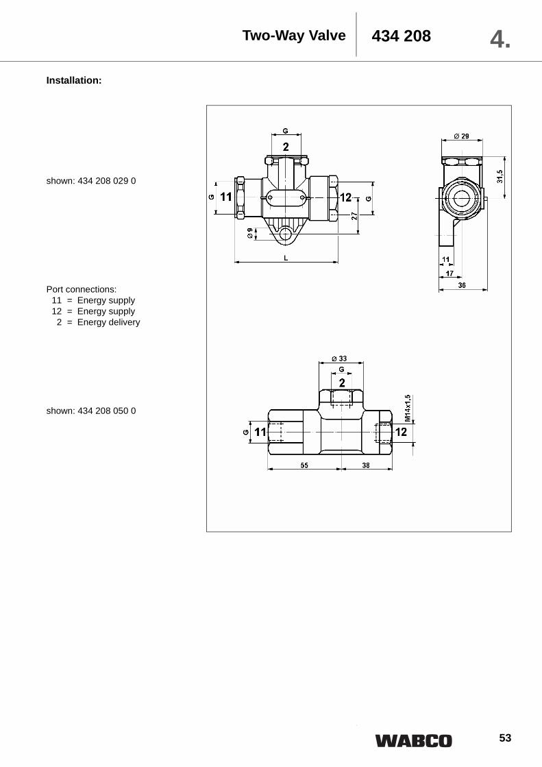
434 208 4.Installation:
Two-Way Valve
shown: 434 208 029 0
Port connections:11 = Energy supply12 = Energy supply2 = Energy delivery
shown: 434 208 050 0

54 2
441 0094. Pressure Switch
Purpose:The pressure switch is used toswitch on or off electrical units andlamps.
Operation:Circuit CloserWhen the rated pressure set at theswitch is reached, diaphragm (c) israised, closing contact plates (b).
Contact plates (b) will open againwhen the pressure drops.
Circuit BreakerWhen the rated pressure set at theswitch is reached, diaphragm (e) israised, opening contact plates (d).
Contact plates (d) will close againwhen the pressure drops.
To adapt either switch for varioustypes of operation, the response
pressure values can be adjustedwithin a certain range by means ofadjusting screw (a).
Maintenance:No special maintenance is neces-sary beyond the legal requirements.
Installation Requirements:Depending on the type of switchused, the single-pole pressureswitch can be fitted either anywherein the pressure pipe or directly in anappliance. Switches of Type I arefastened using a screw M8, ensuringproper earth contact. The connect-ing cable needs to be fitted with acable ear.
Circuit Closer Circuit Breaker

552
441 009 4.
Technical Data:
Installation:
Pressure Switch
Part NumberCircuit closer 441 009 001 0
Circuit breaker 441 009 100 0 441 009 101 0Operating pressure 10 bar max.
Breaking pressure
set at 0.3 ± 0.1 bar 5.0 ± 0.2 bar
adjustable from 0.1 to 1.2 bar 1.0 to 5.0 bar
Thread of pipe connections M22 x 1.5 - 15.5 deepType of protection in accordancewith DIN 40 050 IP 64
Operating voltage (DC) 30 V max.
Electrical breaking capacity underinductive load and with direct current 2 A max.
Permissible medium Air
Operating temperature range - 40��C to + 80° C
Weight 0.22 kg
Adjusting screw

56 2
441 0424.
Installation instructions supplied with the device.
Part Number 441 042 000 0Operating pressure 15 bar max.
Breakingpressure
2 � 4 1.8 bar4 � 2 1.3 bar
Type of protection in accordance with DIN 40 050 IP 55
Operating voltage DC
Electrical breaking capacity 8 A max. (ohmic load)7 A max. (inductive load: L/R 3ms)
Thread of pipe connections G 1/4″ ISO 228
Permissible medium Air, Oil
Operating temperature range - 25��C to + 70° CWeight 0.36 kg
Installation:
Pressure Switch
Technical Data:
4
P1
2
+
4
P1
2
+
1
3
7
9
5
11
1 3 7 95 11
Switching pressure 2 4
Sw
itch
ing
pre
ssu
re
4
2
bar
bar Range of adjustment
opening or closing
4 2 1 N
ø 4,4
15,5
ø 5,2
ø 5
,2
ø 6 32
40
ø 5
,2
13,5
60
19
41
≥ 70
34 34 31,5
30
96
SW 27
PG 13,5
116
109
13 12,5
angle included in switch package
Space requiredfor switch setting

572
452 000 4.Fastening clamp
Part Number 893 510 240 2For hose couplings 452 300 / 452 302In accordance with Standard C DIN 74 294
Weight 0.1 kg
Accessories for Hose Couplings
Dummy coupling with fastening
Part Number 452 402 000 0 452 402 002 0For hose couplings 452 200 / 952 200 452 201
In accordance with Standard VDA 74 344
Weight 0.3 kg
Dummy coupling with chain
Part Number 452 401 000 0 452 401 001 0For hose couplings 452 200 452 301In accordance with Standard VDA 74 343
Weight 0.2 kg

58 2
452 0024. Shut-off cockwith Exhaust
Purpose:To shut off an air line and vent thedown stream line.
Operation:When the lever (a) is parallel to thelongitudinal axis of the stop cock theeccentric shaft (c) pushes valve (d)to the left against the spring (e). Airpasses unrestricted from port 1through the inlet (f) to the line leadingfrom port 2. If the lever (a) is turnedthrough 90 degrees to its stop, thespring (e) moves valve (d) to the
right and the inlet (f) is closed. Theline leading from port 2 is ventedthrough the exhaust drilling (b).
Maintenance:No special maintenance is neces-sary beyond the legal requirements.
Installation Requirements:The stop cock may be installed atany angle using the two mountingholes.
Technical Data:
Part Number 452 002 107 0Operating pressure 10 bar max.
Thread of pipe connections M22 x 1.5 - 12 deep
lever actuation a / b 90°Permissible medium Air
Operating temperature range - 40��C to + 80° C
Weight 0.5 kg
Installation:
Port connections:1 = Energy supply2 = Energy delivery

592
452 80 . 4.Purpose:To connect the compressed air brakingsystem of the motor vehicle to that ofthe trailer.
Operation:When attaching the trailer, handle (b)is pushed downwards; this causes pro-tective caps (a) and (d) to open. TheDuo-Matic trailer portion is placed be-low the protective caps and handle (b)is released. Torsion spring (e) actsupon protective caps (a) and (d), push-ing the trailer portion against theautomatic closing valves (c), causingthem to open: Compressed air nowreaches the trailer.
Maintenance:No special maintenance is necessarybeyond the legal requirements. Whenattaching the trailer, make sure that allcontact surfaces are clean. In theevent of any leakage, change thevalves or junk rings.
Installation Requirements:The Duo-Matic Quick Coupling is to beinstalled as per DIN 1728 standard.
Installation schematic:
Duo-Matic Quick Couplingfor Trailers

60
452 80 .4.
Installation:
Part Number 452 802 009 0Tractor portion
452 804 012 0Trailer portion
Operating pressure 10 bar max.
Nominal diameter 9 mm
Permissible medium AirOperating temperaturerange - 40��C to + 80° C
Hose connec-tion piece
Ø 10 mmØ 14 mm –
893 129 373 2893 120 414 4
Sealing ring M16 x 1.5 811 401 057 4
Weight 1.0 kg 0.2 kg
Duo-Matic Quick Couplingfor Trailers
Technical Data:
Port connections:1 = Energy supply4 = Service
Trailer portion
Tractor portion

61
452 80 . 4.
Installation schematic:
Purpose:To connect the compressed air brakingsystem of the semi-trailer tractor to thatof the semi-trailer.
Operation:When attaching the semi-trailer, han-dle (b) is pushed downwards; thiscauses protective caps (a) and (d) toopen. The Duo-Matic tractor portion isplaced below the protective caps andhandle (b) is released. Torsion spring(e) acts upon protective caps (a) and(d), pushing the tractor portion againstthe contact surface. The automaticshut-off valves (c) open and com-pressed air reaches the semi-trailer.
Maintenance:No special maintenance is necessarybeyond the legal requirements. Whenattaching the semi-trailer, make surethat all contact surfaces are clean. Inthe event of any leakage, change thevalves or junk rings.
Installation Requirements:The Duo-Matic Quick Coupling is to beinstalled as per DIN 1728 standard.
Duo-Matic Quick Couplingfor Semi-trailers

62
452 80 .4.Technical Data:
Duo-Matic Quick Couplingfor Semi-trailers
Installation:
Part Number 452 803 005 0Semi-trailer portion
452 805 004 0Tractor portion
Operating pressure 10 bar max.
Nominal diameter 9 mm
Permissible medium AirOperating temperaturerange - 40��C to + 80° C
Hose connec-tion piece
Ø 10 mmØ 14 mm –
893 129 373 2893 120 414 4
Sealing ring M16 x 1.5 811 401 057 4
Weight 1.0 kg 0.3 kg
Port connections:1 = Energy supply4 = Service
Tractor portion
Semi-trailer portion
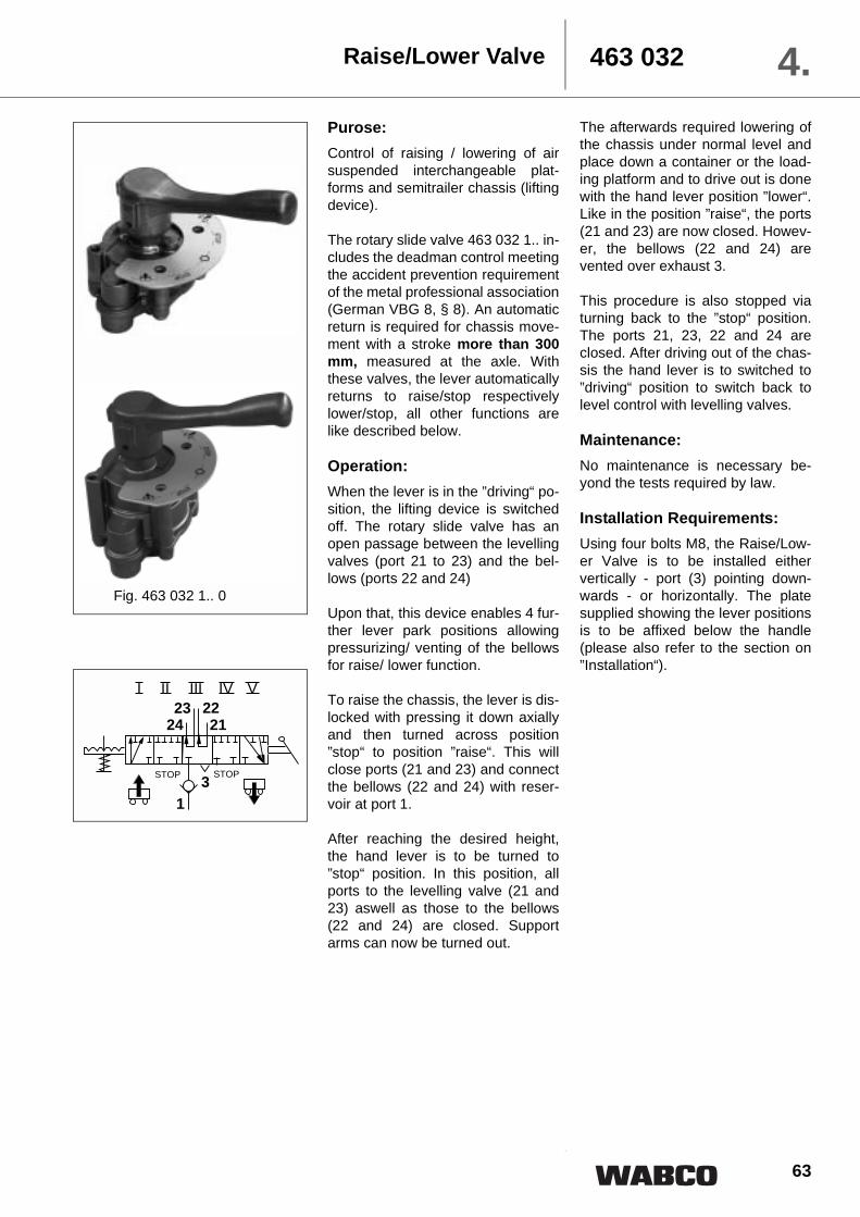
63
463 032 4.Purose:Control of raising / lowering of airsuspended interchangeable plat-forms and semitrailer chassis (liftingdevice).
The rotary slide valve 463 032 1.. in-cludes the deadman control meetingthe accident prevention requirementof the metal professional association(German VBG 8, § 8). An automaticreturn is required for chassis move-ment with a stroke more than 300mm, measured at the axle. Withthese valves, the lever automaticallyreturns to raise/stop respectivelylower/stop, all other functions arelike described below.
Operation:When the lever is in the ”driving“ po-sition, the lifting device is switchedoff. The rotary slide valve has anopen passage between the levellingvalves (port 21 to 23) and the bel-lows (ports 22 and 24)
Upon that, this device enables 4 fur-ther lever park positions allowingpressurizing/ venting of the bellowsfor raise/ lower function.
To raise the chassis, the lever is dis-locked with pressing it down axiallyand then turned across position”stop“ to position ”raise“. This willclose ports (21 and 23) and connectthe bellows (22 and 24) with reser-voir at port 1.
After reaching the desired height,the hand lever is to be turned to”stop“ position. In this position, allports to the levelling valve (21 and23) aswell as those to the bellows(22 and 24) are closed. Supportarms can now be turned out.
The afterwards required lowering ofthe chassis under normal level andplace down a container or the load-ing platform and to drive out is donewith the hand lever position ”lower“.Like in the position ”raise“, the ports(21 and 23) are now closed. Howev-er, the bellows (22 and 24) arevented over exhaust 3.
This procedure is also stopped viaturning back to the ”stop“ position.The ports 21, 23, 22 and 24 areclosed. After driving out of the chas-sis the hand lever is to switched to”driving“ position to switch back tolevel control with levelling valves.
Maintenance:No maintenance is necessary be-yond the tests required by law.
Installation Requirements:Using four bolts M8, the Raise/Low-er Valve is to be installed eithervertically - port (3) pointing down-wards - or horizontally. The platesupplied showing the lever positionsis to be affixed below the handle(please also refer to the section on”Installation“).
Raise/Lower Valve
Fig. 463 032 1.. 0
212223
24
13
STOP STOP
I II III IV V

64
463 0324.Technical Data:
Raise/Lower Valve
Part Number 463 032 020 0 463 032 026 0 463 032 022 0 463 032 023 0Operating pressure 10 bar max.
Nominal diameter21, 23 = 12.6 mm2 ( Ø 4 mm)22, 24 = 28.3 mm2 (Ø 6 mm)
1, 3 = 63.6 mm2 (Ø 9 mm)
Type single circuit21 = 12.6 mm2
22 = 28.3 mm2
1, 3 = 63.6 mm2
Thread of pipe connections M12 x 1.5 -12 deep1 = M16 x 1.5 -12 deep M12 x 1,5 - 12 deep
Check valve (port 1) with without with
Permissible medium Air
Operating temperature range - 40° C to + 80° COperating torque 7 Nm max.
Weight 1.4 kg
Part Number 463 032 120 0 463 032 130 0Operating pressure 8,5 bar max.
Nominal diameter21, 23 = 12.6 mm2 ( Ø 4 mm)22, 24 = 28.3 mm2 (Ø 6 mm)
1, 3 = 63.6 mm2 (Ø 9 mm)
Thread of pipe connections M12 x 1.5 -12 deep1 = M16 x 1.5 -12 deep
Permissible medium Air
Operating temperature range - 40° C to + 80° C
Operating torque 9 Nm max. Weight 1.5 kg
Position I Raise II Stop III Travelling IV Stop V LowerPort 21 closed closed inter-
connectedclosed closed
Port 22 pressurized closed closed exhausted
Port 23 closed closed inter-connected
closed closedPort 24 pressurized closed closed exhausted
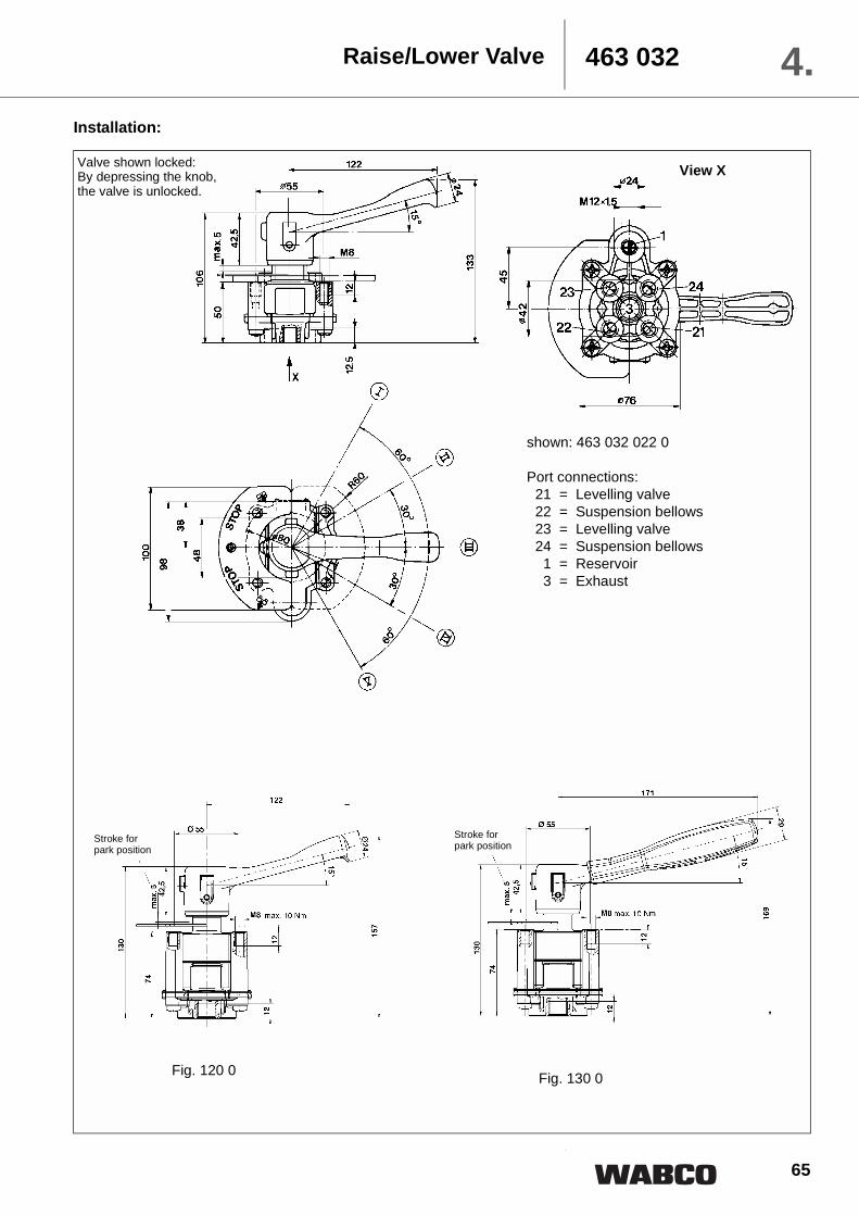
65
Installation:
Raise/Lower Valve 463 032 4.
2
shown: 463 032 022 0
Port connections:21 = Levelling valve22 = Suspension bellows23 = Levelling valve24 = Suspension bellows1 = Reservoir3 = Exhaust
Valve shown locked: By depressing the knob, the valve is unlocked.
Fig. 120 0 Fig. 130 0
View X
Stroke for park position
Stroke for park position

66
Release Valve463 0344.
2
Purpose:Exhausting the front wheel brake ac-tuators when the trailer is uncoupled.
Operation:To release the front wheel brake ac-tuators, piston (b) is pushed fullyhome via actuator button (a), thusblocking the passage from port 1 toport 2. The compressed air at port 2is exhausted to atmosphere via port3-4 and via the hose coupling of thesupply line.
If piston (b) has not yet been pulledout manually when the trailer isagain coupled to the motor vehicle,the supply pressure coming from the
motor vehicle via port 3-4 will do thisautomatically. The release valve isagain in its driving position in whichports 1 and 2 are connected.
Maintenance:No special maintenance is neces-sary beyond the legal requirements.
Installation Requirements:The release valve can be mounteddirectly on the flange of the trailerbrake valve, using two screws M8, orin the pipe upstream from the adapt-er valve.
Technical Data:
Part Number 463 034 005 0Operating pressure 10 bar max.
Flange seal Part Number 897 312 870 4
Operating torquePort 1; 2 55 Nm max. Port 3-4 50 Nm max.
Permissible medium Air
Operating temperature range - 40° C to + 80° CWeight 0.33 kg
Installation:
Port connections:1 = Energy supply2 = Energy delivery
3-4 = Exhaust or pilot connection
Threads of pipe connections:1, 2 = M22 x 1.53-4 = M16 x 1.5

67
463 036 4.3/2 Directional Control Valve
Purpose:Alternate connection of the serviceline (consumer) with the pressureline or the exhaust, the valve lockinginto either position.
Operation:When turning knob (a) is actuated ina rotary direction, piston (b) ismoved downwards via a cam. Outlet(d) closes and inlet (c) opens, andthe compressed air at Port 1 flowsinto the service line via Port 2. Whenturning knob (a) is turned the otherway, piston (b) is returned to its orig-
inal position by the force of thecompression spring. Inlet (c) closesand the service line is exhausted viaoutlet (b) and Port 3.
Maintenance:No special maintenance is neces-sary beyond the legal requirements.
Installation Requirements:The 3/2 directional control valve isfitted in the pipe system with Outlet 3pointing downward. It is fastened ona console (bore Ø 26) using counternut M28 x 1.5.
Technical Data:
Part Number 463 036 016 0Operating pressure 10 bar max.
Thread of pipe connections M16 x 1.5 - 12 deepfor VOSS plug connection
Nominal diameter 4 mm
Permissible medium AirOperating temperature range - 40��C to + 80° C
Weight 0.25 kg
Installation:
Port connections:1 = Energy supply2 = Energy delivery3 = Exhaust
pressurizing process commences

68
463 0844. Lift Axle Control Valve
Purpose:The lift axle control valve is used tomanually or automatically raise or toautomatically drop the lift axle(s)once the axle(s) which is (are) incontact with the ground havereached their permissible load.
Variants• 463 084 000 0 for mechanical
actuation
• 463 084 010 0 for electrical actuation
• 463 084 020 0 fully automatic,pneumatic actuation
Operation:For dropping the lift axle, com-pressed air from port 21 (airsuspension bellows) flows via duct(k) through the throttle of the checkvalve (d) to port 41 (balance reser-voir) and through duct (f) intoChamber B. Once the actuatingpressure set by means of screw (c)has been reached, piston (e) israised. The compressed air nowflows via duct (g) into Chamber A,moving tappet (b) into its upper endposition. Port 1 (supply) is closed.Port 20 and Chambers D and E areconnected via Outlet 3. Tappets (hand i) move to their lower stop posi-tions and a connection is establishedbetween the ports for the air suspen-sion bellows (23 and 24).
To raise the lift axle, the actuatingknob (a) is pushed in (possible onlyif piston (e) is lowered) and the airsupply flows via port 20 to the down-stream lifting bellows. At the sametime, compressed air flows via duct(j) into Chambers D and E, forcingtappets (h and i) upwards againstthe compression springs. The con-nection of the ports for the airsuspension bellows (21 and 22) aswell as (23 and 24) is closed and thecompressed air from the lift axle's airsuspension bellows (ports 22 and24) is released to atmosphere afterflowing via tappets (h and j), Cham-ber C and Exhaust 3.Funktion of port 42 refer to page 75.
Maintenance:No special maintenance is neces-sary beyond the legal requirements.
Installation Requirements:This valve can be fastened using 3stud bolts M6 [A] (tightening torque10 Nm) or 2 screws M8 [B], tighte-ning torque 20 Nm (through holes 9mm are provided on the valve).The fitting position for the lifting axlecontrol valve is shown on page 70.
32324
20
II
I
22 21 1 42 41
43 44
32324
20II
I
22 21 1 4241
32324
20
II
I
22 21 1 4241
Fig. 000
Fig. 010
Fig. 020
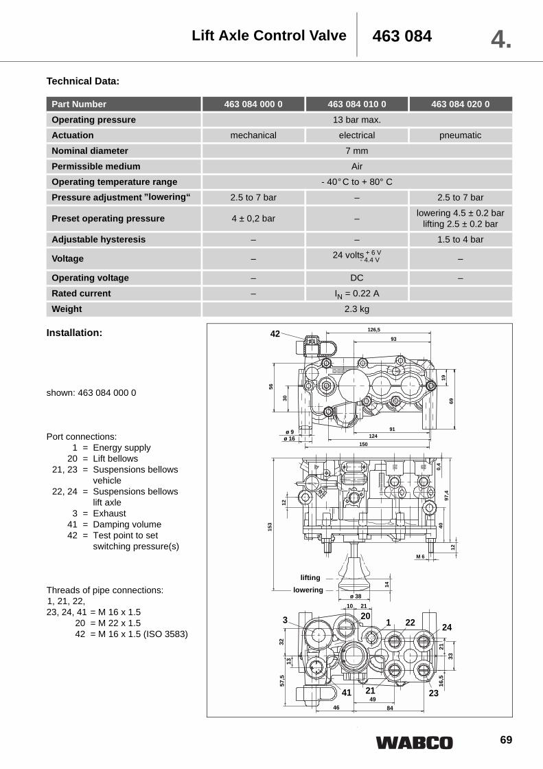
69
463 084 4.Lift Axle Control Valve
Technical Data:
Part Number 463 084 000 0 463 084 010 0 463 084 020 0Operating pressure 13 bar max. Actuation mechanical electrical pneumatic
Nominal diameter 7 mm
Permissible medium AirOperating temperature range - 40��C to + 80° C
Pressure adjustment ”lowering“ 2.5 to 7 bar – 2.5 to 7 bar
Preset operating pressure 4 ± 0,2 bar – lowering 4.5 ± 0.2 barlifting 2.5 ± 0.2 bar
Adjustable hysteresis – – 1.5 to 4 bar
Voltage – 24 volts + 6 V- 4.4 V –
Operating voltage – DC –
Rated current – IN = 0.22 A
Weight 2.3 kg
Installation:
shown: 463 084 000 0
Port connections:1 = Energy supply
20 = Lift bellows21, 23 = Suspensions bellows
vehicle22, 24 = Suspensions bellows
lift axle3 = Exhaust
41 = Damping volume42 = Test point to set
switching pressure(s)
Threads of pipe connections:1, 21, 22,23, 24, 41 = M 16 x 1.5
20 = M 22 x 1.542 = M 16 x 1.5 (ISO 3583)
126,5
93
19
69
91124
150
30
56
0,4
97,4
40
12
M 6
14
153
12
HEBEN
SENKEN
ø 9 ø 16
ø 38
3213
57,5
21
33
16,5
49
8446
3 201 22 24
232141
42
2110
liftinglowering

70
463 0844. Lift Axle Control Valve
Installation:
Installation position:
126,593
91124
150
ø 9 ø 16
4214,7 10
35,5
9
ø 4
M 2
7x1
30
56
1969
4476
0,4
97,4
4012
M 6
111
12
51,5
44 43
8
21
33
16,5
49
84
1 22 24
2321
32
13
57,5
46
3 20
41
2110
2133
16,5
4984
1 22 24
2321
3213
57,5
46
320
41
2110
0,4
97,4
40
12
M 6
111
12
148,
5
SW 30
91124
150
ø 9 ø 16
ø 32
126,5
93
42
30
56
1969
shown: 463 084 020 0shown: 463 084 010 0
A A
BB
A A
BB
Optional only

71
463 084 4.Lift Axle Control Valve
Setting Instructions: After having correctly installed thevalve, according to instructions, theswitching pressure(s) must be set.
1. 463 084 000 0 mechanically operated version (cir-cuit diagram 841 801 448 0 seePage 32)
Push in the operating knob.The switching pressure to lower thelift axle must be set to a pressurewhich ensures that the admissibleaxle load is not exceeded.
To do so, a test hose, with pressuregauge and pressure reduction valve,must be connected to port 42. In-crease the pressure at the test portto determine the switching pressureat which the operating button comesout, exhausting the lift bellows andpressurising the lift axle bellows (liftaxle drops).
If the switching pressure is too high,it can be reduced by screwing outthe setting screw. If too low, it can beincreased by screwing in the settingscrew.
The switching pressure for automat-ic drop must always be checkedusing rising pressure (to avoid incor-rect setting due to hysteresis).
Once adjustment is complete tightenthe lock nut on the adjusting screwand cover with the cap provided.
2. 463 084 010 0 electrically operated version (circuitdiagram 841 801 447 0 see Page 32)
Pressure switch 441 009 101 0 (set-ting range 1.0 to 5.0 bar) must beinstalled according to the circuit dia-gram.The pressure switch setting methodis similar to that used to set the me-chanically operated version.
3. 463 084 020 0 fully automatic pneumatic version(circuit diagram 841 801 449 0 seePage 33)
Two switching pressures must beset.First remove the protection cap(SW30; M = 45 ± 5 Nm), then usinga cross slotted screw driver (size 2)adjust the setting screw (A) down-wards until it reaches its stop.
The switching pressure for auto-matic lowering can now be set.Using a 12 mm allen key adjust set-ting screw (B) using the methodpreviously described for the me-chanical version.
Once the lowering pressure hasbeen set the switching pressure forautomatic lifting can be set by adjust-ing screw (A).
The lifting pressure must always beset using falling pressure.
Replace protection cap.The difference between the liftingand lowering switching pressuresmust be at least 0.4 bar higher thanthe increase in the bellows pressureon the non-lifting axle(s) when anaxle is lifted.
Enclosed
Ran
ge o
f adj
ustm
ent
Width acrossflats10M = 4 ± 1Nm
Width across flats 12M = 15 Nm max.
lowering
lifting
stop
size 2
M = 1.5 Nm max. = 5 turns>

72
463 0844. Damping reservoir
Damping reservoir 463 084 020 2 for lifting axlecontrol valve:
To prevent from unintentional lower-ing of the lifting axle, a dampingvolume is required. the damping res-
ervoir is a low cost solution since it isdirectly fitted to port 41 of lifting axlecontrol valve 463 084 ... 0
Technical Data:
Part Number 463 084 020 2Volume 1 dm3
Ambient temperature: - 40��C to + 60° C
Operating pressure max.: pe = 8.5 bar at 60° Cpe = 10 bar at 40° C
Operating torque 26+4 Nm
Material Plastic
Colour black
male stud thread M 16 x 1.5Installation position optional
Installation:

73
Purpose:The range of the conventional lifting-axle valve has been expanded with aone circuit variant. This means a lift-ing axle can be automaticallycontrolled as traction help by thetrailer EBS D depending on the cur-rent axle load. Electrical control andmonitoring is performed by the trailermodulator.
Operation:The supply line, coming from reser-voir is connected to port 11. Thearmature (d) which forms the valvecore keeps inlet (c) closed and thelifting bag port 21 is connected to ex-haust 31.
When a current reaches solenoidcoil, armature (d) is lifted, and inlet(c) is opened. The supply air movesthe piston (a) down against the forceof spring (b). The connection of thebellows (12 with 21) is closed andcompressed air from the bellows ofthe lifting axle (port 22) is ventingthrough piston (a) and exhaust 31 toatmosphere. In parallel, supply airpressurises from port 11 via port 21the downstream lifting bag.
To lower the lifting axle, the currentto the solenoid coil is interrupted andarmature (d) closes inlet (c). Thecompressed air upon piston (a) isventing via solenoid coil and exhaust32. The pressure spring lifts piston(a) and the lifting axle control valve isist inital position where ports (12 with22) and (21 with 31) are connected.
A traction help with residual pres-sure holding is possible afterunscrewing the vent.
To do this, a line is routed from thevent to the 3/2-way solenoid valvefor residual pressure holding andport IN/OUT 1 of the modulator mustbe connected via cable 449 764 ... 0.The lifting axle valve vent (connec-tion 3) is shut off by a 2-way valve,vented accordingly by the EBS Dmodulator and the maximum possi-ble bellows pressure is retained. Thetraction help can be activated by abutton. (Diagram 841 801 923 0 see page34)
Technical Data:
Part Number 463 084 030 0Operating pressure 13 bar max. Nominal diameter Ø 8 mm
Permissible medium Air
Operating temperature range - 40��C to + 80° C
Voltage 24 volts + 6 V - 4.4 V
Operating voltage DCRated current IN = 0.22 A
Type of protection in accordance with DIN 40050 IP 6K9K
Weight 1.5 kg
Lifting Axle Control Valve 463 084 4.
2

74
Lifting Axle Control Valve463 0844.
2
Installation:
Port connections:1 = Energy supply
21 = Port lifting bag12 = bellows vehicle22 = bellows lifting axle
31, 32 = Exhaust
Threads of pipe connections: 11, 12,21, 22 = M 16 x 1.5
connecting cable EBS Modulator: Part Number Length L1 (mm) Length L2 (mm)
449 664 050 0 4000 1000
449 664 190 0 4000 4000449 664 253 0 6000 6000
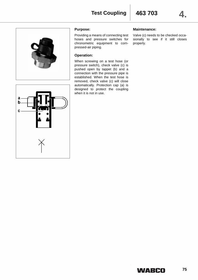
75
463 703 4.Purpose:Providing a means of connecting testhoses and pressure switches forchronometric equipment to com-pressed-air piping.
Operation:When screwing on a test hose (orpressure switch), check valve (c) ispushed open by tappet (b) and aconnection with the pressure pipe isestablished. When the test hose isremoved, check valve (c) will closeautomatically. Protection cap (a) isdesigned to protect the couplingwhen it is not in use.
Maintenance:Valve (c) needs to be checked occa-sionally to see if it still closesproperly.
Test Coupling

76
463 7034.Installation:
Test Coupling
1) outside Ø x wall thickness
2) for hose
Part Number D1 D2 L1 L2 L3 L4 SW 1 SW 2 SW 3 Fig.463 703 120 0 M 16 x 1.5 – 36 10 – – 22 – – 1
463 703 115 0 M 22 x 1.5 – 36 9 – – 28 – – 1463 703 116 0 M 12 x 1.5 – 38 7 – – 17 – – 2
463 703 118 0 M 14 x 1.5 – 38 7 – – 17 – – 2
463 703 119 0 M 18 x 1.5 – 39 8 – – 24 – – 2463 703 308 0 15 x 1.5 1) M 22 x 1.5 99.5 51.5 48 38 28 28 22 3
463 703 025 0 10 x 1 1) M 16 x 1.5 87 49 38 48 22 22 22 4
463 703 026 0 10 x 1 1) M 22 x 1.5 88 49 39 48 22 28 22 4463 703 027 0 15 x 1.5 1) M 22 x 1.5 90.5 51.5 39 48 28 28 22 4
463 703 036 0 11 x 3.5 2) M 16 x 1.5 75.5 27.5 48 38 22 28 22 5
463 710 998 0 M 22 x 1.5 M 12 x 1.5 25.5 55.5 40 – – – – 6463 710 999 0 M 12 x 1.5 M 12 x 1.5 25.5 32.5 40 – – – – 7
Fig. 1 Fig. 2 Fig. 3
Fig. 5 Fig. 6 Fig. 7
L3 L1
D2
D1
L2
Fig. 4
Recommended