Air Accident Investigation Sector
Incident
- Final Report - AAIS Case No AIFN/0015/2016
Failure of the Left Wing Landing Gear to Extend
Operator: Emirates Make and Model: Airbus A380-861 Nationality and Registration: The United Arab Emirates, A6-EDQ Place of Occurrence: Dubai International Airport State of Occurrence: The United Arab Emirates Date of Occurrence: 9 November 2016
Incident Investigation Final Report №. AIFN/0015/2016, issued on 14 June 2017 i
Air Accident Investigation Sector General Civil Aviation Authority
The United Arab Emirates
Incident Brief GCAA AAI Report No.: AIFN/0015/2016
Operator: Emirates
Aircraft Type and Registration: Airbus A380-861, A6-EDQ
MSN 080
Number and Type of Engines: Four, Engine Alliance GP7000
Date and Time (UTC): 9 November 2016
Location: Dubai International Airport
Type of Flight: Commercial, passenger
Persons Onboard: 372
Injuries: None
Investigation Objective This Investigation is performed pursuant to the United Arab Emirates (UAE) Federal Act
20 of 1991, promulgating the Civil Aviation Law, Chapter VII - Aircraft Accidents, Article 48. It is in compliance with Part VI, Chapter 3 of the UAE Civil Aviation Regulations, in conformity with Annex 13 to the Convention on International Civil Aviation, and in adherence to the Air Accidents and Incidents Investigation Manual.
The sole objective of this Investigation is to prevent aircraft accidents and incidents. It is not the intent of the investigation to apportion blame or liability.
Investigation Process The occurrence involved an Airbus A380-861 passenger Aircraft, registration A6-EDQ,
and was notified to the Air Accident Investigation Sector (AAIS) by phone call to the Duty Investigator Hotline Number +971 50 641 4667.
After the initial on-site investigation, the occurrence was classified as an ‘incident’. Accordingly, the AAIS notified the Bureau d’Enquêtes et d’Analyses (BEA), as France is the State of Manufacture, and the International Civil Aviation Organization (ICAO).
An Investigation Team was formed in line with the Annex 13 obligations of the UAE being the State of Occurrence.
This Report does not resort to any proof production procedure for the determination of civil or criminal liability, and is issued in accordance with paragraph 3.1 of Annex, which is incorporated in the UAE legal system.
Incident Investigation Final Report №. AIFN/0015/2016, issued on 14 June 2017 ii
The use of this Report for any purpose other than that of preventing future accidents, may lead to erroneous interpretations and conclusions.
All AAIS reports are publicly available at:
http://www.gcaa.gov.ae/en/epublication/pages/investigationreport.aspx
Notes:
1 Whenever the following words are mentioned in this Report with the first letter Capitalized, it shall mean:
- (Aircraft) - the aircraft involved in this incident
- (Investigation) - the investigation into this incident
- (Incident) - this investigated incident
- (Operator) - Emirates
- (Report) - this incident investigation Final Report
- (Commander) - the commander of the flight
- (Copilot) - the copilot of the flight.
2 Unless otherwise mentioned, all times in this Report are Coordinated Universal Time (UTC), (UAE local time minus 4 hours).
3 Photos used in the text of this Report are taken from different sources and are adjusted from the original for the sole purpose to improve clarity of the Report. Modifications to images used in this Report are limited to cropping, magnification, file compression, or enhancement of color, brightness, contrast or insertion of text boxes, arrows or lines.
Incident Investigation Final Report №. AIFN/0015/2016, issued on 14 June 2017 iii
Abbreviations and Definitions AAIS Air Accident Investigation Sector
AIFN Accident/incident file number
AMM Aircraft maintenance manual
AOT (Airbus) Alert Operator Transmission
ARFFS Airport fire service
ARM Aircraft recovery manual
ATC Air traffic control
ATPL Airline transport pilot license
BEA Bureau d’Enquêtes et d’Analyses
BLG Body landing gear
CCTV Closed-circuit television
CVR Cockpit voice recorder
DCAA Dubai Civil Aviation Authority
EASA European Aviation Safety Agency
ECAM Electronic centralized aircraft monitoring
EUA Emergency unlock actuator
E/WD Engine warning display
FCOM Flight crew operating manual
FFCM Free fall control module
FDR Flight data recorder
GCAA General Civil Aviation Authority of the United Arab Emirates
ICAO The International Civil Aviation Organization
MCC (Operator’s) maintenance control center
MPD Maintenance planning document
MSN Manufacturer serial number
NCC (Operator’s) network control center
SD Systems display
UAE The United Arab Emirates
UTC Coordinated universal time
VML Correction for defective distant, intermediate and near vision
WLG Wing Landing Gear
Incident Investigation Final Report №. AIFN/0015/2016, issued on 14 June 2017 iv
Synopsis
On 9 November 2016, at 1405 UTC, an Emirates Airbus A380-861 Aircraft, operating scheduled flight number EK002, departed from London Heathrow, the United Kingdom, for Dubai International Airport, the United Arab Emirates. The Aircraft had two flight crewmembers, 25 cabin crewmembers, and 345 passengers onboard.
The departure and the initial cruise continued normally until the flight crew received an electronic centralized aircraft monitoring (ECAM) message, indicating that the green hydraulic system temperature was high and the system subsequently overheated. The flight crew followed the flight crew operating manual (FCOM) instructions and isolated the green hydraulic system, which resulted in a number of hydraulic system limitations, including the need to extend the landing gear using the emergency gear extension method.
Consequently, the flight crew prepared to lower the landing gear using the emergency gear extension, or free-fall method. The loss of green hydraulic system pressure also resulted in restricted use of the nose gear steering, slow flap and slat extension, and limited brake function.
On the final approach at about 4,000 feet, eight minutes prior to landing, the landing gear was selected down. The landing gear indication showed that the landing gear, except for the left wing gear, was down and locked. This caused the flight crew to declare an emergency four minutes prior to landing.
As the green hydraulic system had been isolated, the landing gear could not have been retracted in the event of a go-around. Had a go-around been flown it would have entailed a significant increase in drag and fuel consumption. With the remaining fuel as a consideration, and notwithstanding the left wing gear indication, the Commander elected to continue the approach and land.
After an uneventful landing at 2022 UTC, the flight crew communicated with Dubai International Airport staff and it was decided to tow the Aircraft from the runway to the assigned stand F20, which was adjacent to the exit taxiway. After arrival at the stand, it became evident that the left wing gear had not been released by the emergency extension system and was still in its bay. The passengers and crew disembarked and no injuries were reported.
The Air Accident Investigation Sector (AAIS) determines that the cause of the failure of the emergency unlock actuators to release the left wing landing gear was the flexure endurance fatigue damage to the independent channel A and channel B emergency unlock actuator command wires. The flexure endurance fatigue was induced by wind effect acting on the inadequately secured wiring loom during the landing gear operation.
Two prompt safety recommendations were issued by AAIS to the European Aviation Safety Agency (EASA) to ensure that the Aircraft manufacturer determines the root cause of the unlock actuator wire damage and that the manufacturer develops a design improvement to eliminate the possibility of future wire damage that could result in emergency landing gear freefall system failures.
Two safety recommendations were issued in this Report to the Operator to revise their network control center procedures and to provide towing instructions. Two recommendations were issued to the Aircraft manufacturer, to amend current information in the FCOM and to provide instructions in aircraft documentations to safely tow an aircraft from the runway, with passengers and freight onboard, in similar conditions to those described in this Report.
Incident Investigation Final Report №. AIFN/0015/2016, issued on 14 June 2017 v
Contents Incident Brief ................................................................................................................................ i
Investigation Objective ................................................................................................................. i
Investigation Process ................................................................................................................... i
Abbreviations and Definitions ..................................................................................................... iii
Synopsis .................................................................................................................................... iv
1. Factual Information ................................................................................................................. 1
1.1 History of the Flight ...................................................................................................... 1
1.2 Injuries to Persons ....................................................................................................... 2
1.3 Damage to Aircraft ....................................................................................................... 2
1.4 Other Damage ............................................................................................................. 2
1.5 Personnel Information.................................................................................................. 2
1.6 Aircraft Information ...................................................................................................... 2
1.6.1 Aircraft data ................................................................................................ 2
1.6.2 Hydraulic system and temperature annunciations ...................................... 3
1.6.3 Landing gear system .................................................................................. 4
1.6.4 Landing gear extension and retraction system ........................................... 4
1.6.5 Landing gear indication and alerting system ............................................... 5
1.7 Meteorological Information .......................................................................................... 6
1.8 Aids to Navigation ........................................................................................................ 6
1.9 Communication............................................................................................................ 6
1.9.1 Flight crew .................................................................................................. 6
1.9.2 Operator’s network control center ............................................................... 7
1.9.3 Air traffic control ......................................................................................... 7
1.9.4 Ground handling agent ............................................................................... 7
1.9.5 Dubai Airports ............................................................................................ 8
1.10 Aerodrome Information ................................................................................................ 8
1.11 Flight Recorders .......................................................................................................... 8
1.12 Wreckage and Impact Information ............................................................................... 9
1.12.1 Recovery from runway ............................................................................... 9
1.12.2 Landing gear safety pins ............................................................................ 9
1.13 Medical and Pathological Information .......................................................................... 9
1.14 Fire .............................................................................................................................. 9
1.15 Survival Aspects .........................................................................................................10
1.16 Tests and Research ...................................................................................................10
1.16.1 Landing gear troubleshooting ....................................................................10
1.16.2 Left wing landing gear unlock wires ...........................................................10
1.16.3 Free fall control modules (FFCMs) ............................................................11
1.16.4 Left wing landing gear uplock ....................................................................11
Incident Investigation Final Report №. AIFN/0015/2016, issued on 14 June 2017 vi
1.16.5 Green hydraulic system temperature sensor .............................................11
1.16.6 Airbus Alert Operator Transmission (AOT) ................................................11
1.17 Organizational and Management Information .............................................................12
1.17.1 Flight crew operating manual (FCOM) instructions ....................................12
1.17.2 Dubai Airports recovery procedures ..........................................................12
1.17.3 Airbus aircraft recovery manual (ARM) ......................................................13
1.17.4 The Operator’s engineering procedures manual ........................................13
1.17.5 Fuel planning .............................................................................................13
1.18 Additional Information .................................................................................................13
1.18.1 A380 landing gear maintenance tasks .......................................................13
1.18.2 A6-EDQ maintenance records ...................................................................14
1.18.4 Airbus A380 landing tests with WLG retracted ...........................................14
1.19 Useful or Effective Investigation Techniques ..............................................................14
1.19.1 Airbus flight test video recording................................................................14
2. Analysis ................................................................................................................................ 15
2.1 The Failure of the Emergency Unlock Actuator and its Consequences .......................15
2.2 Aircraft Recovery ........................................................................................................15
2.3 Crew Performance and Emergency Handling .............................................................16
2.4 Communication...........................................................................................................16
3. Conclusions .......................................................................................................................... 18
3.1 General ......................................................................................................................18
3.2 Findings ......................................................................................................................18
3.2.1 Findings relevant to the Aircraft .................................................................18
3.2.2 Findings relevant to the crew .....................................................................19
3.2.2 Findings relevant to the Operator and flight operation ...............................19
3.2.3 Findings relevant to the Aircraft manufacturer ...........................................19
3.3 Causes .......................................................................................................................20
3.4 Contributing Factors to the Incident ............................................................................20
4. Safety Recommendations ..................................................................................................... 21
4.1 General ......................................................................................................................21
4.2 Prompt Safety Recommendations ..............................................................................21
4.2 Safety Actions Taken ..................................................................................................21
4.2.1 Airbus Alert Operator Transmission (AOT) ................................................21
4.2.2 Airbus service bulletin (SB) and modification .............................................21
4.3 Final Report Safety Recommendations ......................................................................22
4.3.1 Emirates ....................................................................................................22
4.3.2 Airbus Industrie .........................................................................................22
Incident Investigation Final Report №. AIFN/0015/2016, issued on 14 June 2017 vii
List of tables
Table 1. Crew information
Table 2. Aircraft general data
List of figures
Figure 1. Landing gear gravity extension switches
Figure 2. Emergency unlock actuators
Figure 3. Aircraft landing gear indication
Figure 4. System Display/Wheel page
Figure 5. Left wing landing gear not down and locked
Figure 6. SD Wheel page showing left wing landing gear condition
Figure 7. Aircraft arrival at passenger stand
Figure 8. Left wing landing gear
Figure 9. Left wing landing gear retracted
Figure 10. Tomography of wire No 3233-522 DR18 pin 4 5GF2A [Source: Airbus]
Figure 11. WLG flight test [Source: Airbus]
Figure 12. BLG flight test [Source: Airbus]
List of appendices
Appendix 1. Airbus 380 FCOM L/G LDG WITH 1 ABNORM WING OR BODY L/G
Appendix 2. Airbus 380 FCOM L/G LDG WITH 2 ABNORM WING L/Gs
Appendix 3. Airbus 380 FCOM HYD G (Y) SYS OVHT
Appendix 4. Airbus 380 FCOM HYD G (Y) SYS PRESS LO
Incident Investigation Final Report №. AIFN/0015/2016, issued on 14 June 2017 1
1. Factual Information
1.1 History of the Flight
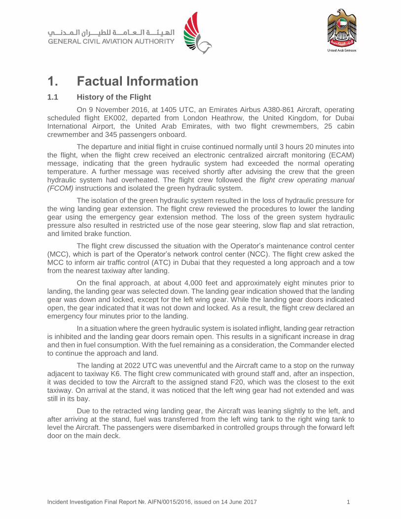
On 9 November 2016, at 1405 UTC, an Emirates Airbus A380-861 Aircraft, operating scheduled flight EK002, departed from London Heathrow, the United Kingdom, for Dubai International Airport, the United Arab Emirates, with two flight crewmembers, 25 cabin crewmember and 345 passengers onboard.
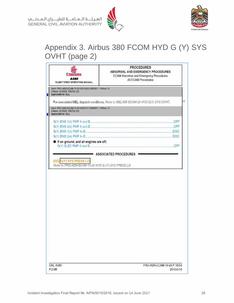
The departure and initial flight in cruise continued normally until 3 hours 20 minutes into the flight, when the flight crew received an electronic centralized aircraft monitoring (ECAM) message, indicating that the green hydraulic system had exceeded the normal operating temperature. A further message was received shortly after advising the crew that the green hydraulic system had overheated. The flight crew followed the flight crew operating manual (FCOM) instructions and isolated the green hydraulic system.
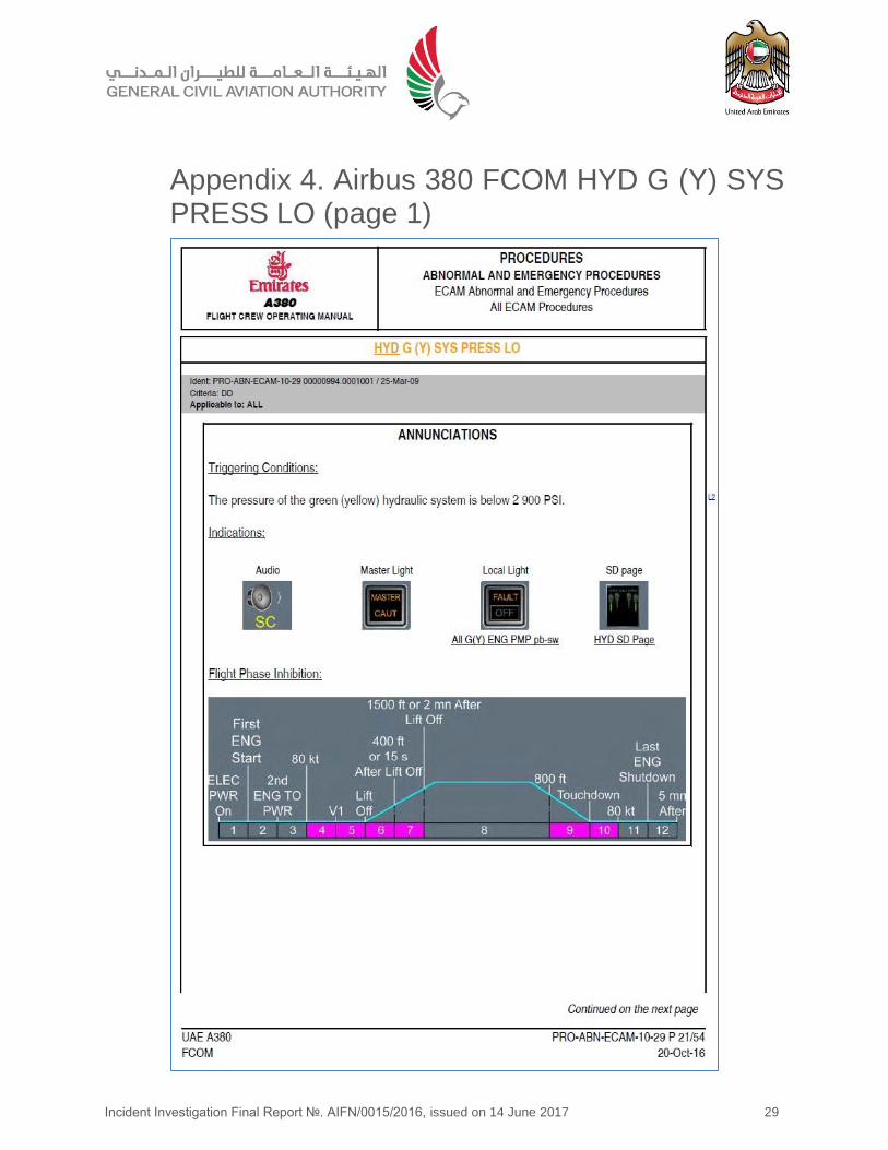
The isolation of the green hydraulic system resulted in the loss of hydraulic pressure for the wing landing gear extension. The flight crew reviewed the procedures to lower the landing gear using the emergency gear extension method. The loss of the green system hydraulic pressure also resulted in restricted use of the nose gear steering, slow flap and slat retraction, and limited brake function.
The flight crew discussed the situation with the Operator’s maintenance control center (MCC), which is part of the Operator’s network control center (NCC). The flight crew asked the MCC to inform air traffic control (ATC) in Dubai that they requested a long approach and a tow from the nearest taxiway after landing.
On the final approach, at about 4,000 feet and approximately eight minutes prior to landing, the landing gear was selected down. The landing gear indication showed that the landing gear was down and locked, except for the left wing gear. While the landing gear doors indicated open, the gear indicated that it was not down and locked. As a result, the flight crew declared an emergency four minutes prior to the landing.
In a situation where the green hydraulic system is isolated inflight, landing gear retraction is inhibited and the landing gear doors remain open. This results in a significant increase in drag and then in fuel consumption. With the fuel remaining as a consideration, the Commander elected to continue the approach and land.
The landing at 2022 UTC was uneventful and the Aircraft came to a stop on the runway adjacent to taxiway K6. The flight crew communicated with ground staff and, after an inspection, it was decided to tow the Aircraft to the assigned stand F20, which was the closest to the exit taxiway. On arrival at the stand, it was noticed that the left wing gear had not extended and was still in its bay.
Due to the retracted wing landing gear, the Aircraft was leaning slightly to the left, and after arriving at the stand, fuel was transferred from the left wing tank to the right wing tank to level the Aircraft. The passengers were disembarked in controlled groups through the forward left door on the main deck.
Incident Investigation Final Report №. AIFN/0015/2016, issued on 14 June 2017 2
1.2 Injuries to Persons
There were no injuries to persons as a result of the Incident.
1.3 Damage to Aircraft
The Aircraft was undamaged.
1.4 Other Damage
There was no damage to property or the environment.
1.5 Personnel Information
Table 1 provides flight crew information at the time of the Incident.
Table 1. Crew information
Commander Copilot
Age 51 28
Gender Male Male
License ATPL ATPL
Valid to 21 February 2017 9 September 2023
Issuing State The United Arab Emirates The United Arab Emirates
Rating Airbus 380 Airbus 380
Total hours 14,720 hours 4,951 hours
Total hours on type 3,058 hours 1,010 hours
Medical class 1 1
Valid to 31 May 2017 8 February 2017
Medical limitation VML restriction (correction for defective distant, intermediate and near vision)
None
The Commander and Copilot operated flight EK001 from Dubai to London on 8 November 2016, which provided for a 24-hour layover. Both were off-duty on 6 November and 7 November 2016.
1.6 Aircraft Information
1.6.1 Aircraft data
Table 2 provides Aircraft information at the time of the Incident.
Table 2. Aircraft general data
Manufacturer: Airbus
Model: A380-861
Manufacture serial number: 080
Date of manufacture: 18 April 2011
Incident Investigation Final Report №. AIFN/0015/2016, issued on 14 June 2017 3
Nationality and registration mark: The United Arab Emirates, A6-EDQ
Name of the owner: Emirates
Name of the operator: Emirates
Certificate of Airworthiness
Number: Original issue date: ARC valid to:
UAE-COA-0006 28 October 2011 27 October 2017
Certificate of Registration
Number: Issue date:
UAE-COR-0059 2 October 2013
Date of delivery 28 October 2011
Total hours since new 20,980
Total cycles since new 3,543
Last inspection and date: A-check, 23 July 2016
Total hours since last inspection: 1,301
Total cycles since last inspection: 216
The Airbus A380-861 is a double-deck wide body aircraft, powered by four Engine Alliance GP7000 engines. The flight deck’s main instruments are presented on eight identical and interchangeable liquid crystal display units, providing a primary flight display, navigation display, two multi-function displays, an engine warning display and a systems display.
1.6.2 Hydraulic system and temperature annunciations
Eight engine driven pumps, and four electrical pumps, provide hydraulic pressure for two independent (green and yellow) hydraulic systems. These systems operate the flight controls, landing gear extension and retraction, flaps, brakes, steering, and cargo doors.
The yellow hydraulic system operates flight controls, steers the rear body landing gear wheels, retracts and extends the body landing gear, and provides pressure for the body landing gear brakes.
The green hydraulic system operates flight controls, steers the nose landing gear, operates the cargo door, retracts and extends the nose and wing landing gear, and provides pressure for the wing landing gear brakes.
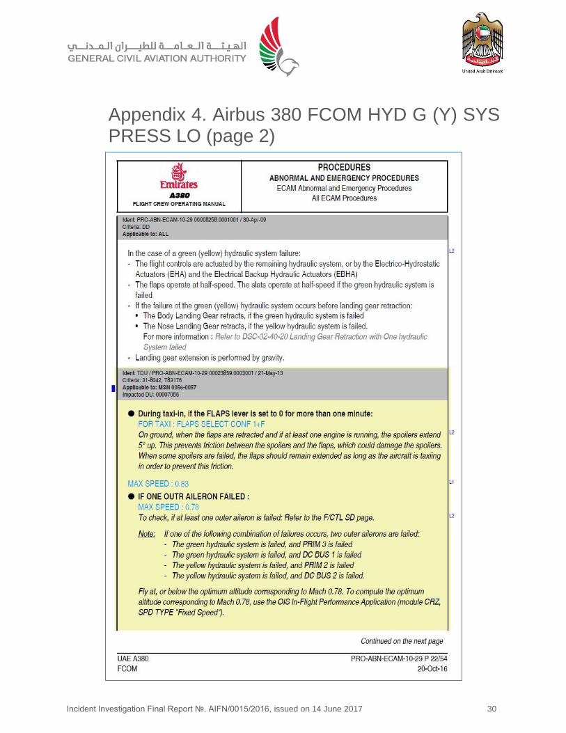
The loss of either the yellow or the green system will reduce the speed for flap extension and increase the landing distance as half of the ground spoilers will not deploy.
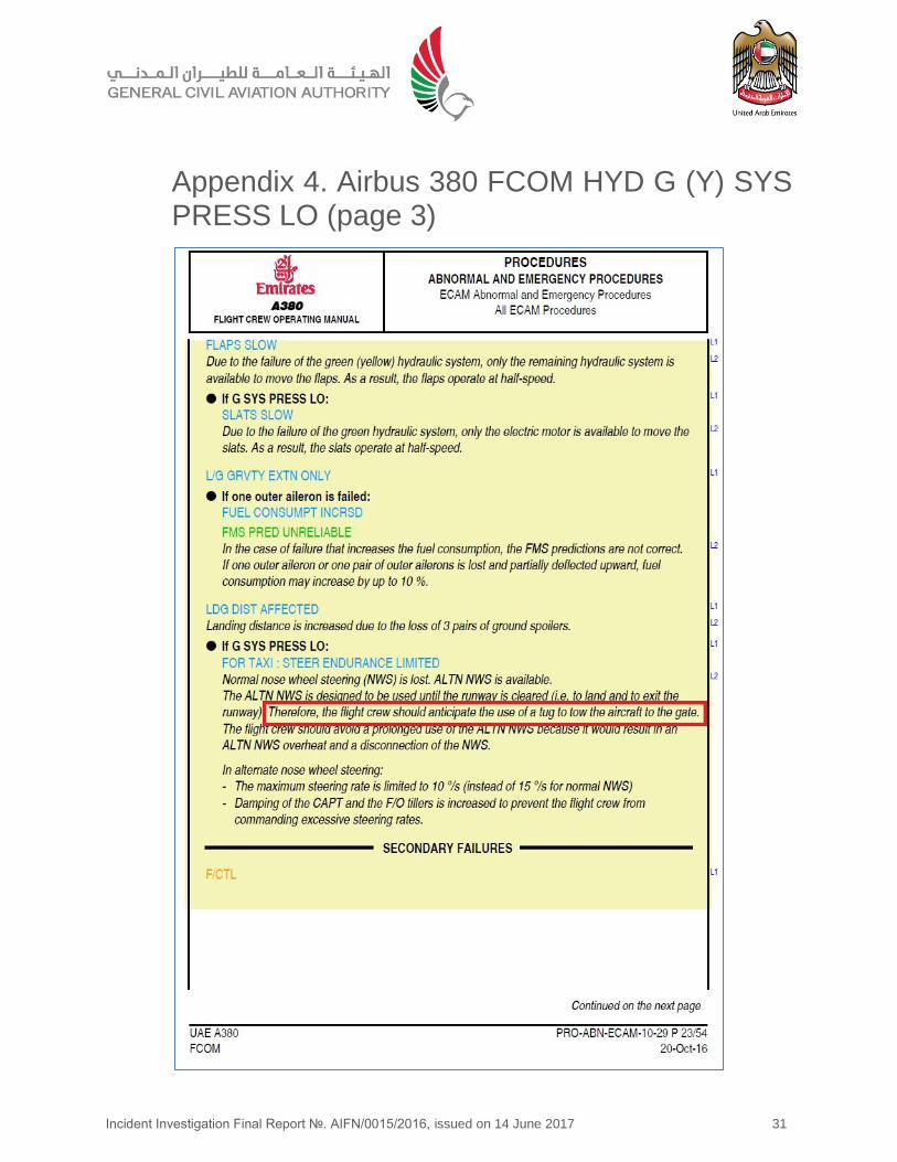
The loss of the green hydraulic system will result in the loss of normal nose wheel steering. The alternative nose gear steering has limited capacities and is designed only to allow the aircraft to exit the runway. The maximum steering rate in the alternative mode is 10 degrees per second in comparison with 15 degrees per second in normal mode. Without the green hydraulic system, the nose gear and wing landing gear can only be extended using the emergency free fall system. Once the landing gear is extended, retraction is inhibited.
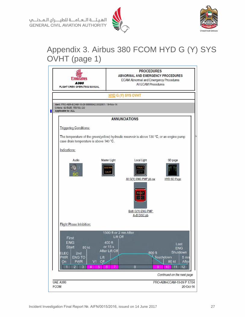
When the hydraulic system fluid temperature in the reservoir exceeds 95°C, or the engine pump case drain temperature exceeds 120°C, a hydraulic system high temperature alert will occur.
Incident Investigation Final Report №. AIFN/0015/2016, issued on 14 June 2017 4
When the hydraulic system fluid in the reservoir exceeds 130°C, or the engine pump case drain temperature exceeds 140°C, a hydraulic system overheat alert will occur.
The loss of the green hydraulic system may result in an increase of up to 10% in fuel consumption during flight if one outer aileron or one pair of outer ailerons deflect upwards. Fuel predictions from the flight management system are no longer correct.
According to the abnormal and emergency procedures in the Operator’s FCOM, when one landing gear remains extended, an increase of 20% in fuel consumption is expected. Flight with the complete landing gear extended may increase the fuel consumption up to 100%.
1.6.3 Landing gear system
The landing gear system consists of a nose landing gear with two wheels, two body landing gear assemblies with six wheels each, and two wing landing gear assemblies with four wheels each. The forward four body landing gear wheels plus the four wing landing gear wheels are fitted with brakes.
The nose wheels and the two rear wheels of each of the body landing gear assemblies are steerable to provide better maneuverability.
Braking pressure is provided by the yellow system to the forward four wheel brakes of each body landing gear assembly, and by the green hydraulic system to the four wheel brakes of each of the wing landing gear assembly brakes. This provides redundancy should one hydraulic system fail.
The nose landing gear is stowed forward into the fuselage, while the body landing gear is stowed tilting rearwards. The wing landing gear tilts inboard into its landing gear bay.
1.6.4 Landing gear extension and retraction system
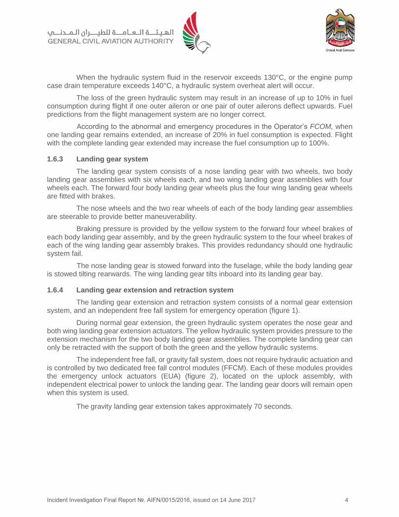
The landing gear extension and retraction system consists of a normal gear extension system, and an independent free fall system for emergency operation (figure 1).
During normal gear extension, the green hydraulic system operates the nose gear and both wing landing gear extension actuators. The yellow hydraulic system provides pressure to the extension mechanism for the two body landing gear assemblies. The complete landing gear can only be retracted with the support of both the green and the yellow hydraulic systems.
The independent free fall, or gravity fall system, does not require hydraulic actuation and is controlled by two dedicated free fall control modules (FFCM). Each of these modules provides the emergency unlock actuators (EUA) (figure 2), located on the uplock assembly, with independent electrical power to unlock the landing gear. The landing gear doors will remain open when this system is used.
The gravity landing gear extension takes approximately 70 seconds.
Incident Investigation Final Report №. AIFN/0015/2016, issued on 14 June 2017 5
1.6.5 Landing gear indication and alerting system
The flight deck landing gear indication provides the status of the nose gear and both the
wing and body landing gear, including the respective door status.
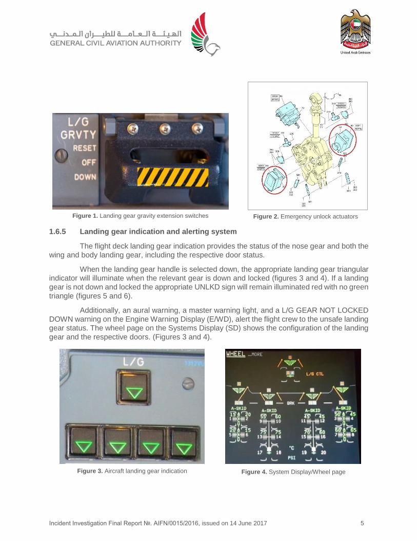
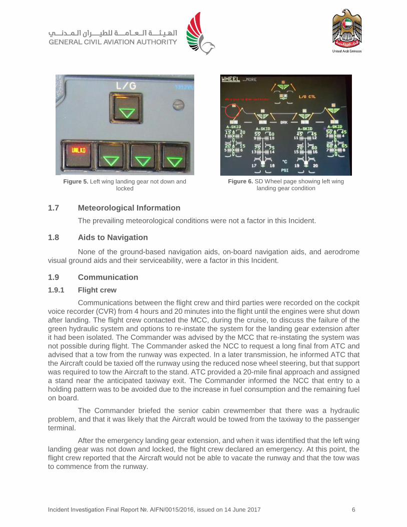
When the landing gear handle is selected down, the appropriate landing gear triangular
indicator will illuminate when the relevant gear is down and locked (figures 3 and 4). If a landing
gear is not down and locked the appropriate UNLKD sign will remain illuminated red with no green
triangle (figures 5 and 6).
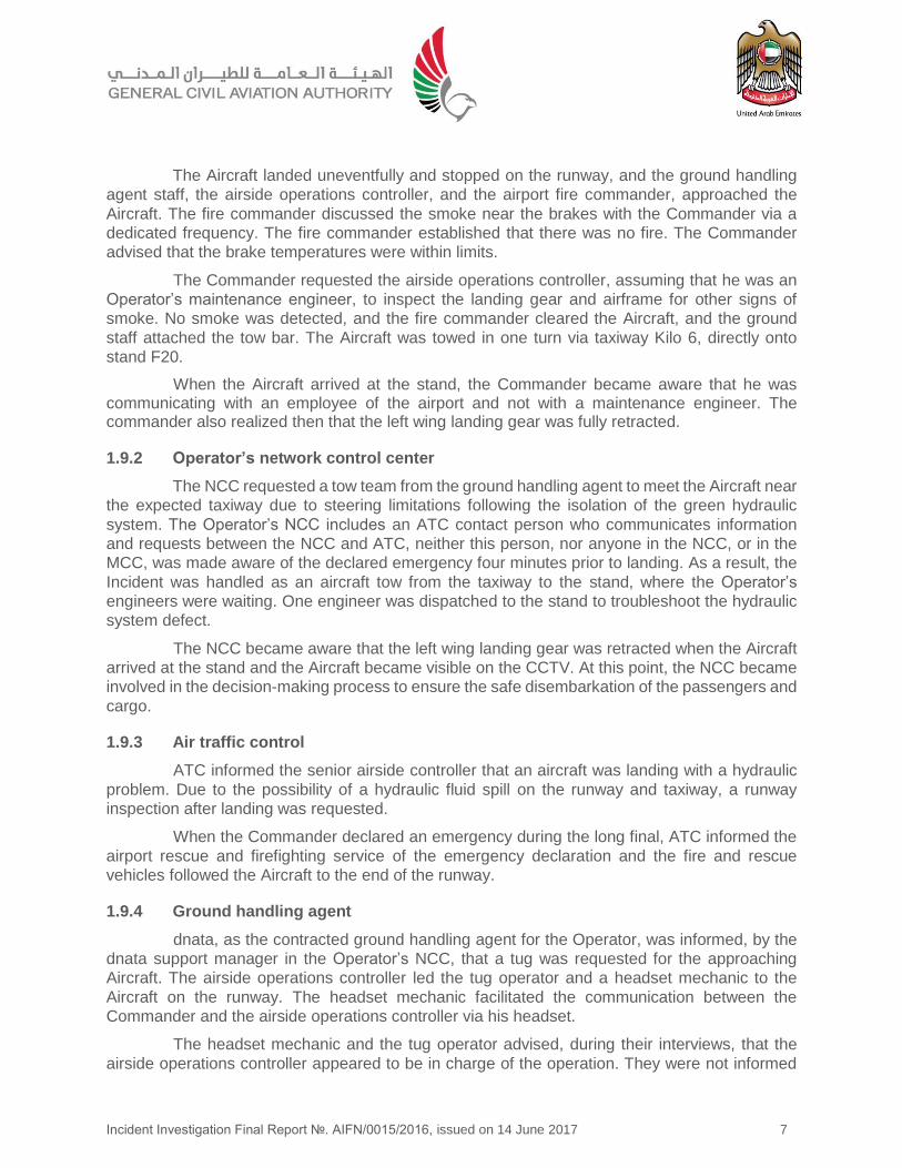
Additionally, an aural warning, a master warning light, and a L/G GEAR NOT LOCKED
DOWN warning on the Engine Warning Display (E/WD), alert the flight crew to the unsafe landing
gear status. The wheel page on the Systems Display (SD) shows the configuration of the landing
gear and the respective doors. (Figures 3 and 4).
Figure 3. Aircraft landing gear indication Figure 4. System Display/Wheel page
Figure 2. Emergency unlock actuators Figure 1. Landing gear gravity extension switches
Incident Investigation Final Report №. AIFN/0015/2016, issued on 14 June 2017 6
1.7 Meteorological Information
The prevailing meteorological conditions were not a factor in this Incident.
1.8 Aids to Navigation
None of the ground-based navigation aids, on-board navigation aids, and aerodrome
visual ground aids and their serviceability, were a factor in this Incident.
1.9 Communication
1.9.1 Flight crew
Communications between the flight crew and third parties were recorded on the cockpit
voice recorder (CVR) from 4 hours and 20 minutes into the flight until the engines were shut down
after landing. The flight crew contacted the MCC, during the cruise, to discuss the failure of the
green hydraulic system and options to re-instate the system for the landing gear extension after
it had been isolated. The Commander was advised by the MCC that re-instating the system was
not possible during flight. The Commander asked the NCC to request a long final from ATC and
advised that a tow from the runway was expected. In a later transmission, he informed ATC that
the Aircraft could be taxied off the runway using the reduced nose wheel steering, but that support
was required to tow the Aircraft to the stand. ATC provided a 20-mile final approach and assigned
a stand near the anticipated taxiway exit. The Commander informed the NCC that entry to a
holding pattern was to be avoided due to the increase in fuel consumption and the remaining fuel
on board.
The Commander briefed the senior cabin crewmember that there was a hydraulic
problem, and that it was likely that the Aircraft would be towed from the taxiway to the passenger
terminal.
After the emergency landing gear extension, and when it was identified that the left wing
landing gear was not down and locked, the flight crew declared an emergency. At this point, the
flight crew reported that the Aircraft would not be able to vacate the runway and that the tow was
to commence from the runway.
Figure 5. Left wing landing gear not down and locked
Figure 6. SD Wheel page showing left wing landing gear condition
Incident Investigation Final Report №. AIFN/0015/2016, issued on 14 June 2017 7
The Aircraft landed uneventfully and stopped on the runway, and the ground handling
agent staff, the airside operations controller, and the airport fire commander, approached the
Aircraft. The fire commander discussed the smoke near the brakes with the Commander via a
dedicated frequency. The fire commander established that there was no fire. The Commander
advised that the brake temperatures were within limits.
The Commander requested the airside operations controller, assuming that he was an
Operator’s maintenance engineer, to inspect the landing gear and airframe for other signs of
smoke. No smoke was detected, and the fire commander cleared the Aircraft, and the ground
staff attached the tow bar. The Aircraft was towed in one turn via taxiway Kilo 6, directly onto
stand F20.
When the Aircraft arrived at the stand, the Commander became aware that he was communicating with an employee of the airport and not with a maintenance engineer. The commander also realized then that the left wing landing gear was fully retracted.
1.9.2 Operator’s network control center
The NCC requested a tow team from the ground handling agent to meet the Aircraft near
the expected taxiway due to steering limitations following the isolation of the green hydraulic
system. The Operator’s NCC includes an ATC contact person who communicates information
and requests between the NCC and ATC, neither this person, nor anyone in the NCC, or in the
MCC, was made aware of the declared emergency four minutes prior to landing. As a result, the
Incident was handled as an aircraft tow from the taxiway to the stand, where the Operator’s
engineers were waiting. One engineer was dispatched to the stand to troubleshoot the hydraulic
system defect.
The NCC became aware that the left wing landing gear was retracted when the Aircraft
arrived at the stand and the Aircraft became visible on the CCTV. At this point, the NCC became
involved in the decision-making process to ensure the safe disembarkation of the passengers and
cargo.
1.9.3 Air traffic control
ATC informed the senior airside controller that an aircraft was landing with a hydraulic
problem. Due to the possibility of a hydraulic fluid spill on the runway and taxiway, a runway
inspection after landing was requested.
When the Commander declared an emergency during the long final, ATC informed the
airport rescue and firefighting service of the emergency declaration and the fire and rescue
vehicles followed the Aircraft to the end of the runway.
1.9.4 Ground handling agent
dnata, as the contracted ground handling agent for the Operator, was informed, by the
dnata support manager in the Operator’s NCC, that a tug was requested for the approaching
Aircraft. The airside operations controller led the tug operator and a headset mechanic to the
Aircraft on the runway. The headset mechanic facilitated the communication between the
Commander and the airside operations controller via his headset.
The headset mechanic and the tug operator advised, during their interviews, that the
airside operations controller appeared to be in charge of the operation. They were not informed
Incident Investigation Final Report №. AIFN/0015/2016, issued on 14 June 2017 8
about the nature of the emergency and only noticed the retracted landing gear in better lighting
conditions, as they approached the passenger terminal.
1.9.5 Dubai Airports
Dubai Airports was informed by ATC that the Aircraft had reported a hydraulic problem
and required a tow to the stand. An airside operations controller was requested to attend the
Aircraft on the runway and assembled a headset mechanic and tug operator.
After the fire commander arrived at the Aircraft and inspected the landing gear, he
advised the flight crew that there was no fire. The Aircraft Commander then asked the headset
mechanic if they were ready to tow the Aircraft. This was confirmed by the airside operations
controller, who instructed the tug operator to attach the tow bar and follow his vehicle. The Aircraft
was then towed at low speed to stand F20 with the airside operations controller leading, and the
senior airside controller and fire service vehicles following the Aircraft.
The airside operations controller advised, during his interview, that he did not
communicate directly with the Commander of the Aircraft during the event.
After the runway inspection, the senior airside controller positioned his vehicle behind
the Aircraft on the runway. He stated that he could not clearly see the landing gear positions due
to the lighting conditions on the runway. He stated in his interview that he did not communicate
directly with the Commander, but followed the Aircraft to the stand.
The senior airside controller and the airside operations controller stated that an engineer
employed by the Operator is normally available on-site to inspect the aircraft and to supervise the
aircraft tow. The senior airside controller and airside operations controller stated that they were
following requests from the Commander to tow the Aircraft from the runway to the stand, and that
it was the responsibility of the tug operator to secure the nose wheel strut with a safety pin prior
to a towing operation.
The interviewed parties advised that they did not perceive any operational pressure to
clear the runway.
1.10 Aerodrome Information
Dubai International Airport (OMDB) is the primary airport in Dubai, the United Arab
Emirates. It is located 4.6 km east of Dubai and has two parallel runways, 12R/30L and 12L/30R.
These are 4,447 meters and 4,351 meters long, respectively. Three passenger terminals are
located south-west and parallel to the runways.
1.11 Flight Recorders
The cockpit voice recorder (CVR), and the flight data recorder (FDR), were removed and
successfully downloaded in the AAIS laboratory.
The CVR recorded phone communications between the flight crew and the NCC in which
the loss of the green hydraulic system was discussed. Conversation between the flight
crewmembers focused on the anticipated 100% increase in fuel consumption once the landing
gear was extended. During the cruise, the Commander initially calculated landing fuel of 7,000
kg, including 4,600 kg reserve fuel, and discussed declaring a low fuel state if required. He revised
his fuel calculation to over 10,000 kg later inflight, taking into account the reduced fuel
consumption during descent.
Incident Investigation Final Report №. AIFN/0015/2016, issued on 14 June 2017 9
When the left wing landing gear did not indicate down and locked, at 3,000 feet, 5
minutes 20 seconds prior to landing, the Commander decided to continue the landing with
remaining fuel as a deciding consideration. After consultation with the Commander, the Copilot
declared an emergency. The Aircraft had 13,300 kg of fuel remaining at that point.
Three minutes 40 seconds prior to landing, the Commander instructed the cabin crew
to prepare for landing. The Aircraft landed with 12,600 kg of fuel on-board. On the runway, the
flight crew felt that the Aircraft was leaning slightly to the left and decided not to proceed towards
the taxiway.
The FDR recorded Aircraft flight parameters useful for the Investigation and provided
the timeline for the Incident.
1.12 Wreckage and Impact Information
As stated in sub-section 1.3 of this Report, the Aircraft was undamaged.
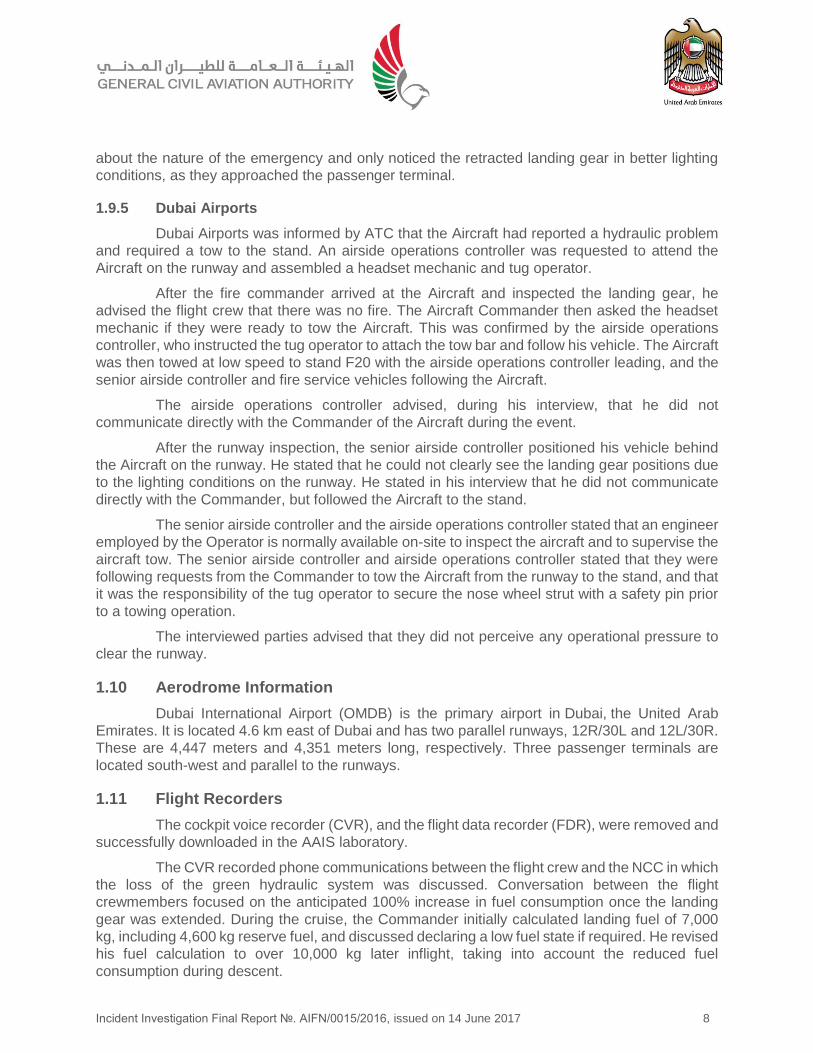
1.12.1 Recovery from runway
Once the Aircraft came to a stop on
the runway, the Commander opened his side
window and requested the airside operations
controller, assuming him to be an aircraft
maintenance engineer, to inspect the main
landing gear because the fire commander had
reported smoke near the landing gear.
After it was confirmed that the smoke
had dissipated, and was not associated with
fire, the airside operations controller instructed
the tug operator to connect the tug and to start
towing the Aircraft to the assigned stand. The
tug followed the airside operations controller
vehicle to stand F20, where company engineers informed the Commander that the left wing
landing gear was in the retracted position.
Due to the tilted attitude of the Aircraft and the missing wing support on the left side,
engineering decided to transfer fuel from the left wing tank to the right wing tank. Passengers
were disembarked in controlled groups through the forward left door on the main deck.
1.12.2 Landing gear safety pins
The Investigation established that the landing gear safety pins had not been fitted prior
to towing the Aircraft from the runway to the passenger terminal.
1.13 Medical and Pathological Information
No medical or pathological investigations were conducted as a result of this Incident,
nor were they required.
1.14 Fire
There was no fire. However, smoke was visible in the vicinity of the landing gear brakes.
Figure 7. Aircraft arrival at passenger stand
Incident Investigation Final Report №. AIFN/0015/2016, issued on 14 June 2017 10
1.15 Survival Aspects
The Aircraft landed uneventfully and remained on the runway until it was towed to the terminal, where the passengers disembarked through the forward left cabin door on the main deck.
1.16 Tests and Research
1.16.1 Landing gear troubleshooting
The Operator requested instructions from the Aircraft manufacturer to ensure that the Aircraft could be towed safely with the left wing landing gear stowed. After receiving a Technical Adaptation document, which included preparation instructions and limitations, the Aircraft was towed to the maintenance hangar for troubleshooting, which started the next day in the presence of AAIS investigators.
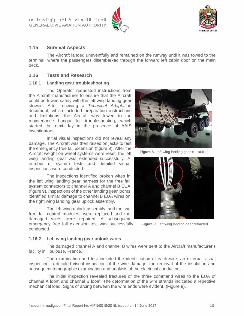
Initial visual inspections did not reveal any damage. The Aircraft was then raised on jacks to test the emergency free fall extension (figure 8). After the Aircraft weight-on-wheel systems were reset, the left wing landing gear was extended successfully. A number of system tests and detailed visual inspections were conducted.
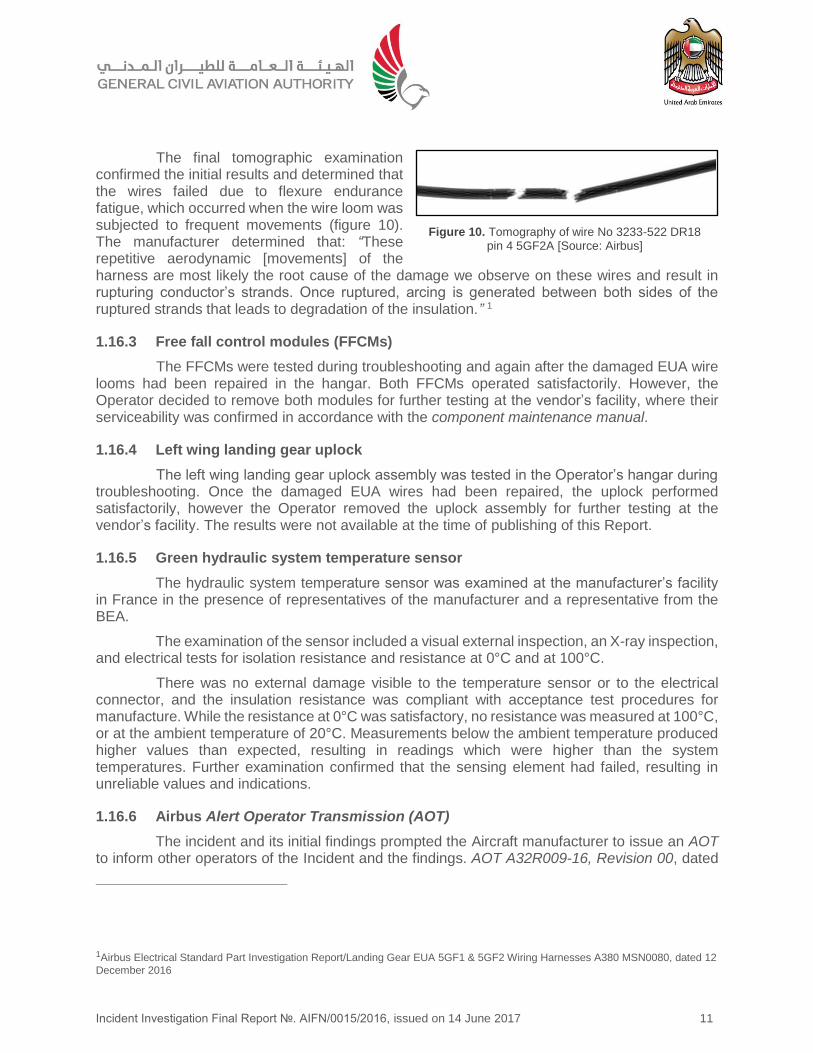
The inspections identified broken wires in the left wing landing gear harness for the free fall system connectors to channel A and channel B EUA (figure 9). Inspections of the other landing gear looms identified similar damage to channel B EUA wires on the right wing landing gear uplock assembly.
The left wing uplock assembly, and the two free fall control modules, were replaced and the damaged wires were repaired. A subsequent emergency free fall extension test was successfully conducted.
1.16.2 Left wing landing gear unlock wires
The damaged channel A and channel B wires were sent to the Aircraft manufacturer’s facility in Toulouse, France.
The examination and test included the identification of each wire, an external visual inspection, a detailed visual inspection of the wire damage, the removal of the insulation and subsequent tomographic examination and analysis of the electrical conductor.
The initial inspection revealed fractures of the three command wires to the EUA of channel A loom and channel B loom. The deformation of the wire strands indicated a repetitive mechanical load. Signs of arcing between the wire ends were evident. (Figure 9).
Figure 8. Left wing landing gear retracted
Figure 9. Left wing landing gear retracted
Incident Investigation Final Report №. AIFN/0015/2016, issued on 14 June 2017 11
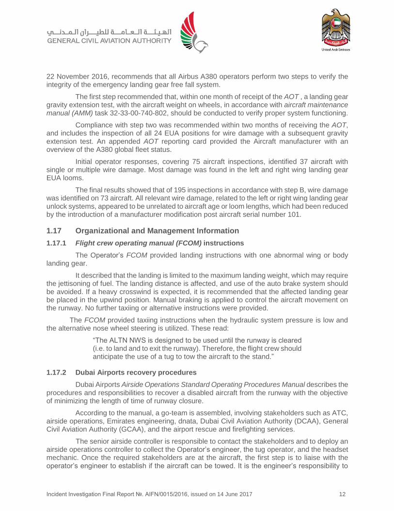
The final tomographic examination confirmed the initial results and determined that the wires failed due to flexure endurance fatigue, which occurred when the wire loom was subjected to frequent movements (figure 10). The manufacturer determined that: “These repetitive aerodynamic [movements] of the harness are most likely the root cause of the damage we observe on these wires and result in rupturing conductor’s strands. Once ruptured, arcing is generated between both sides of the ruptured strands that leads to degradation of the insulation.” 1
1.16.3 Free fall control modules (FFCMs)
The FFCMs were tested during troubleshooting and again after the damaged EUA wire looms had been repaired in the hangar. Both FFCMs operated satisfactorily. However, the Operator decided to remove both modules for further testing at the vendor’s facility, where their serviceability was confirmed in accordance with the component maintenance manual.
1.16.4 Left wing landing gear uplock
The left wing landing gear uplock assembly was tested in the Operator’s hangar during troubleshooting. Once the damaged EUA wires had been repaired, the uplock performed satisfactorily, however the Operator removed the uplock assembly for further testing at the vendor’s facility. The results were not available at the time of publishing of this Report.
1.16.5 Green hydraulic system temperature sensor
The hydraulic system temperature sensor was examined at the manufacturer’s facility in France in the presence of representatives of the manufacturer and a representative from the BEA.
The examination of the sensor included a visual external inspection, an X-ray inspection, and electrical tests for isolation resistance and resistance at 0°C and at 100°C.
There was no external damage visible to the temperature sensor or to the electrical connector, and the insulation resistance was compliant with acceptance test procedures for manufacture. While the resistance at 0°C was satisfactory, no resistance was measured at 100°C, or at the ambient temperature of 20°C. Measurements below the ambient temperature produced higher values than expected, resulting in readings which were higher than the system temperatures. Further examination confirmed that the sensing element had failed, resulting in unreliable values and indications.
1.16.6 Airbus Alert Operator Transmission (AOT)
The incident and its initial findings prompted the Aircraft manufacturer to issue an AOT to inform other operators of the Incident and the findings. AOT A32R009-16, Revision 00, dated
1Airbus Electrical Standard Part Investigation Report/Landing Gear EUA 5GF1 & 5GF2 Wiring Harnesses A380 MSN0080, dated 12
December 2016
Figure 10. Tomography of wire No 3233-522 DR18 pin 4 5GF2A [Source: Airbus]
Incident Investigation Final Report №. AIFN/0015/2016, issued on 14 June 2017 12
22 November 2016, recommends that all Airbus A380 operators perform two steps to verify the integrity of the emergency landing gear free fall system.
The first step recommended that, within one month of receipt of the AOT , a landing gear gravity extension test, with the aircraft weight on wheels, in accordance with aircraft maintenance manual (AMM) task 32-33-00-740-802, should be conducted to verify proper system functioning.
Compliance with step two was recommended within two months of receiving the AOT, and includes the inspection of all 24 EUA positions for wire damage with a subsequent gravity extension test. An appended AOT reporting card provided the Aircraft manufacturer with an overview of the A380 global fleet status.
Initial operator responses, covering 75 aircraft inspections, identified 37 aircraft with single or multiple wire damage. Most damage was found in the left and right wing landing gear EUA looms.
The final results showed that of 195 inspections in accordance with step B, wire damage was identified on 73 aircraft. All relevant wire damage, related to the left or right wing landing gear unlock systems, appeared to be unrelated to aircraft age or loom lengths, which had been reduced by the introduction of a manufacturer modification post aircraft serial number 101.
1.17 Organizational and Management Information
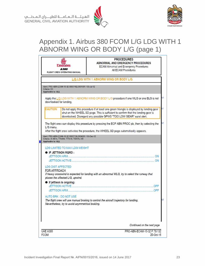
1.17.1 Flight crew operating manual (FCOM) instructions
The Operator’s FCOM provided landing instructions with one abnormal wing or body landing gear.
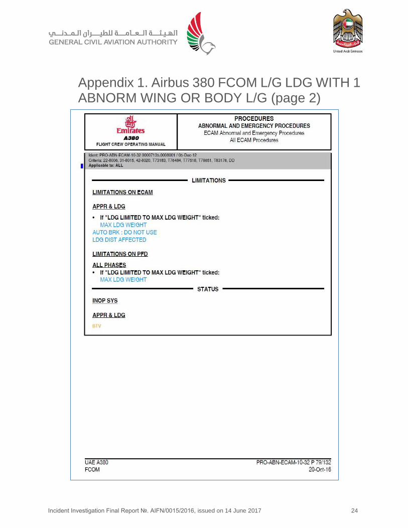
It described that the landing is limited to the maximum landing weight, which may require the jettisoning of fuel. The landing distance is affected, and use of the auto brake system should be avoided. If a heavy crosswind is expected, it is recommended that the affected landing gear be placed in the upwind position. Manual braking is applied to control the aircraft movement on the runway. No further taxiing or alternative instructions were provided.
The FCOM provided taxiing instructions when the hydraulic system pressure is low and the alternative nose wheel steering is utilized. These read:
“The ALTN NWS is designed to be used until the runway is cleared (i.e. to land and to exit the runway). Therefore, the flight crew should anticipate the use of a tug to tow the aircraft to the stand.”
1.17.2 Dubai Airports recovery procedures
Dubai Airports Airside Operations Standard Operating Procedures Manual describes the procedures and responsibilities to recover a disabled aircraft from the runway with the objective of minimizing the length of time of runway closure.
According to the manual, a go-team is assembled, involving stakeholders such as ATC, airside operations, Emirates engineering, dnata, Dubai Civil Aviation Authority (DCAA), General Civil Aviation Authority (GCAA), and the airport rescue and firefighting services.
The senior airside controller is responsible to contact the stakeholders and to deploy an airside operations controller to collect the Operator’s engineer, the tug operator, and the headset mechanic. Once the required stakeholders are at the aircraft, the first step is to liaise with the operator’s engineer to establish if the aircraft can be towed. It is the engineer’s responsibility to
Incident Investigation Final Report №. AIFN/0015/2016, issued on 14 June 2017 13
ensure that the aircraft is safe to move, whereas the tug operator and headset mechanic are responsible to provide support to the team as required.
1.17.3 Airbus aircraft recovery manual (ARM)
The Airbus A380 ARM described procedures for the recovery of an aircraft in certain circumstances, normally when the aircraft is unable to move under its engine power. It covered situations where one or more landing gear assemblies are retracted, collapsed, damaged, or missing. The ARM did not apply when passengers or cargo are on-board.
The AMM covers towing of the aircraft for maintenance purposes and prohibits towing with passengers onboard.
1.17.4 The Operator’s engineering procedures manual
The Operator’s engineering procedures manual described the general requirements for aircraft towing in Procedure 11-08. This procedure did not apply to aircraft towing as part of an aircraft recovery with passengers and cargo onboard, but it was the only document which provides instructions to towing staff.
Procedure 11-08 described that towing staff must be at the aircraft 10 minutes prior to the ‘towing time’ in order to prepare the aircraft. The preparation includes items such as a walk-around inspection to ensure that all cowlings are closed, landing gear doors are closed, ground equipment and maintenance tools are removed, the flight deck is checked for any warning placards and all landing gear safety pins are removed from the flight deck stowage locations and fitted in their respected landing gear positions.
The fitment of the landing gear pins was an item on the Before Towing Checklist, and an entry in the aircraft technical logbook was required to control the fitment of the landing gear safety pins.
1.17.5 Fuel planning
CAR-OPS 1.255 ̶ Fuel Policy, describes the regulatory requirement for operator’s fuel policy including the fuel calculation for departure. The basic procedure includes taxi fuel, trip fuel, contingency fuel, alternate fuel, final reserve fuel, minimum additional fuel, and extra fuel. Standard conditions are applied for the calculation of contingency fuel, final reserve fuel, and minimum additional fuel for holding at 1,500 ft above the destination aerodrome
A review of the Operator’s fuel procedures, and the flight crew’s trip fuel calculation, showed compliance with this requirement.
1.18 Additional Information
1.18.1 A380 landing gear maintenance tasks
Airbus advised that, according to the A380 Maintenance Program Document (MPD), the landing gear free fall test is conducted every 24 months or 3,000 flight hours, whichever comes first. AMM task 32-33-00-710-806 - Operational Check of Emergency Unlock Actuators on Landing Gear and Landing Gear Door Uplocks, included a wiring check of the free fall system from a dedicated connector, and a functional test of the landing gear gravity extension as per AMM task 32-33-00-740-802’s fuel policy - Functional Test of the Landing Gear Gravity Extension with BITE Monitoring Function (Weight on Wheels).
Incident Investigation Final Report №. AIFN/0015/2016, issued on 14 June 2017 14
1.18.2 A6-EDQ maintenance records
Maintenance records, obtained from the Operator, showed that the operational test of the emergency landing gear extension, in accordance with AMM task 32-33-00-710-806-A, was last conducted on the Aircraft on 20 July 2015, when the Aircraft had accumulated 15,555 hours and 2,640 landings. No faults were detected.
1.18.4 Airbus A380 landing tests with WLG retracted
The Aircraft manufacturer advised that the landing procedure, with one wing landing gear or body landing gear retracted, had been tested and validated in the simulator.
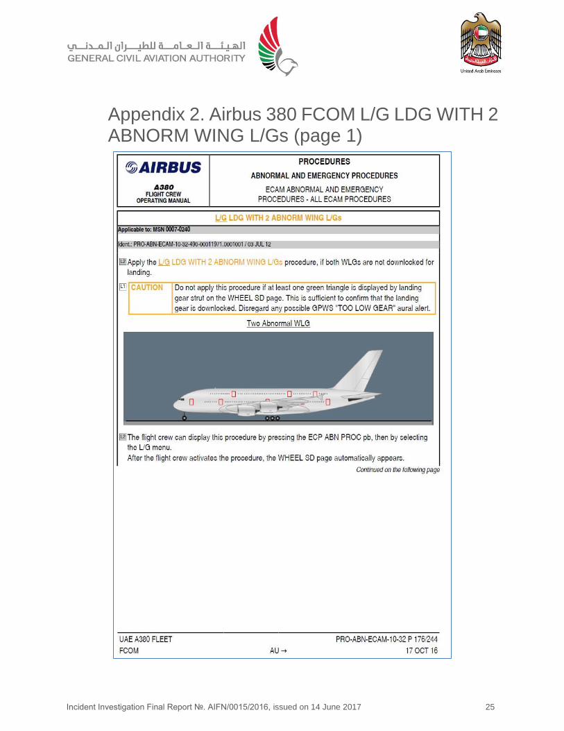
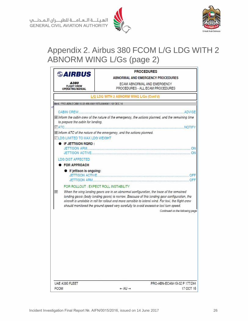
The FCOM procedure for landing with two abnormal wing landing gear units includes a statement reading: “For taxi, the flight crew should monitor the ground speed very carefully to avoid excessive taxi turn speed.” This statement is currently under consideration for inclusion in the FCOM procedure for landing with one abnormal wing landing gear.
1.19 Useful or Effective Investigation Techniques
1.19.1 Airbus flight test video recording
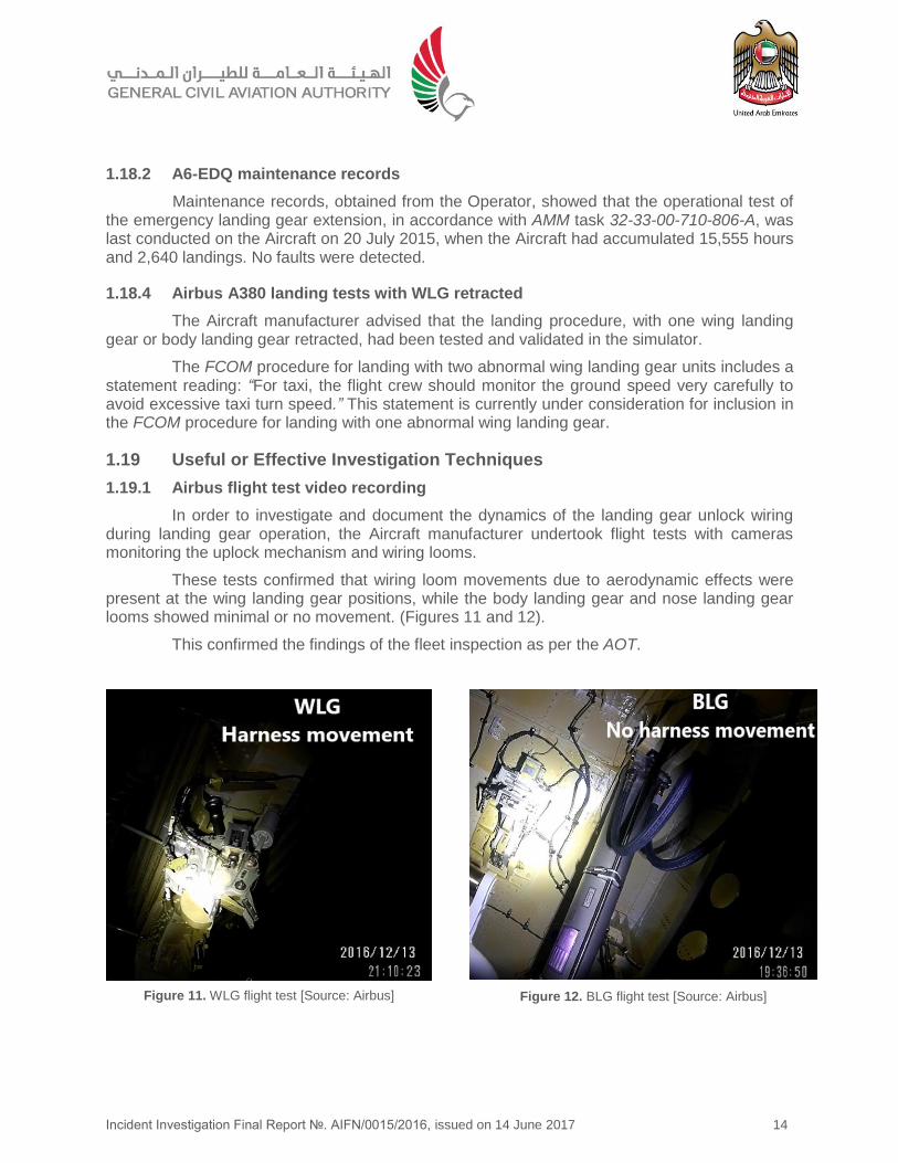
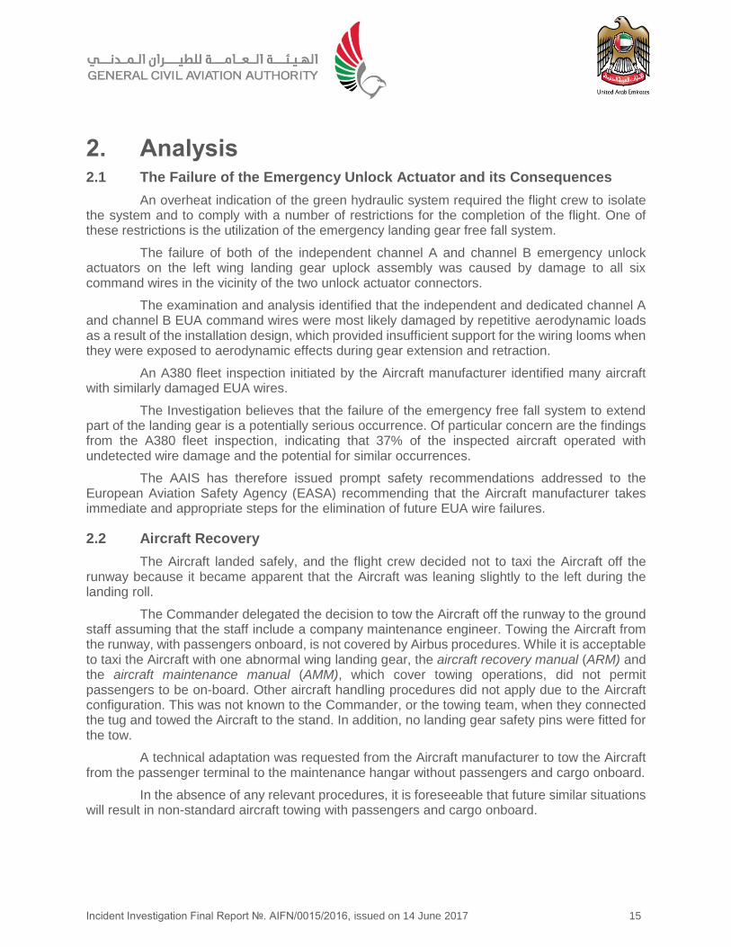
In order to investigate and document the dynamics of the landing gear unlock wiring during landing gear operation, the Aircraft manufacturer undertook flight tests with cameras monitoring the uplock mechanism and wiring looms.
These tests confirmed that wiring loom movements due to aerodynamic effects were present at the wing landing gear positions, while the body landing gear and nose landing gear looms showed minimal or no movement. (Figures 11 and 12).
This confirmed the findings of the fleet inspection as per the AOT.
Figure 11. WLG flight test [Source: Airbus] Figure 12. BLG flight test [Source: Airbus]
Incident Investigation Final Report №. AIFN/0015/2016, issued on 14 June 2017 15
2. Analysis 2.1 The Failure of the Emergency Unlock Actuator and its Consequences
An overheat indication of the green hydraulic system required the flight crew to isolate the system and to comply with a number of restrictions for the completion of the flight. One of these restrictions is the utilization of the emergency landing gear free fall system.
The failure of both of the independent channel A and channel B emergency unlock actuators on the left wing landing gear uplock assembly was caused by damage to all six command wires in the vicinity of the two unlock actuator connectors.
The examination and analysis identified that the independent and dedicated channel A and channel B EUA command wires were most likely damaged by repetitive aerodynamic loads as a result of the installation design, which provided insufficient support for the wiring looms when they were exposed to aerodynamic effects during gear extension and retraction.
An A380 fleet inspection initiated by the Aircraft manufacturer identified many aircraft with similarly damaged EUA wires.
The Investigation believes that the failure of the emergency free fall system to extend part of the landing gear is a potentially serious occurrence. Of particular concern are the findings from the A380 fleet inspection, indicating that 37% of the inspected aircraft operated with undetected wire damage and the potential for similar occurrences.
The AAIS has therefore issued prompt safety recommendations addressed to the European Aviation Safety Agency (EASA) recommending that the Aircraft manufacturer takes immediate and appropriate steps for the elimination of future EUA wire failures.
2.2 Aircraft Recovery
The Aircraft landed safely, and the flight crew decided not to taxi the Aircraft off the runway because it became apparent that the Aircraft was leaning slightly to the left during the landing roll.
The Commander delegated the decision to tow the Aircraft off the runway to the ground staff assuming that the staff include a company maintenance engineer. Towing the Aircraft from the runway, with passengers onboard, is not covered by Airbus procedures. While it is acceptable to taxi the Aircraft with one abnormal wing landing gear, the aircraft recovery manual (ARM) and the aircraft maintenance manual (AMM), which cover towing operations, did not permit passengers to be on-board. Other aircraft handling procedures did not apply due to the Aircraft configuration. This was not known to the Commander, or the towing team, when they connected the tug and towed the Aircraft to the stand. In addition, no landing gear safety pins were fitted for the tow.
A technical adaptation was requested from the Aircraft manufacturer to tow the Aircraft from the passenger terminal to the maintenance hangar without passengers and cargo onboard.
In the absence of any relevant procedures, it is foreseeable that future similar situations will result in non-standard aircraft towing with passengers and cargo onboard.
Incident Investigation Final Report №. AIFN/0015/2016, issued on 14 June 2017 16
2.3 Crew Performance and Emergency Handling
The flight crew became aware of the green hydraulic system problem approximately 3 hours 20 minutes into the flight, and they started to review the alternatives. From the recorded communications, it appears that the flight crew were aware of the limitations to the Aircraft systems and of the effects that the hydraulic problem would have on the remaining portion of the flight. Information was sought from available sources including the Operator’s maintenance control center (MCC), which led to the decision to continue to Dubai with requests to ATC for a long landing and a tow from the taxiway.
One of the Commander’s main concerns, during the preparation for landing, was the anticipated increase in fuel consumption due to the loss of the green hydraulic system and possible aileron deflections. An initial fuel calculation resulted in landing fuel of less than 7,000 kg, which included the required 4,600 kg reserve. The Commander was concerned that being sent to the hold could further reduce the landing fuel, therefore the crew discussed declaring a minimum fuel state, if required. A second calculation resulted in more than 10,000 kg of landing fuel.
The flight crew used the time available to them to prepare for the remainder of the flight, and considered the expected system limitations. At approximately one hour to landing, they had established the sequence for the Aircraft configuration for approach, landing, and taxiing.
At an altitude of 2,600 feet, and 4 minutes 36 seconds before landing, the Commander decided against a go-around due to fuel quantity remaining reasons. The Commander intended to avoid entering the hold prior to encountering the wing landing gear fault. When the problem became apparent, and an emergency was declared, time was running out to access and process more information causing the Commander to focus on his first decision which was to continue the approach and land. The Aircraft landed with 12,600 kg of fuel onboard.
The investigation believes that it is the responsibility of the Operator, in conjunction with the Aircraft manufacturer, to prepare procedures for future similar abnormal situations which will assist flight crew to have quick access to relevant information in time-critical situations.
2.4 Communication
After the Aircraft came to a stop on the runway, the flight crew prepared for the tow by shutting down the engines, and monitoring the brake temperatures. According to the Commander, it was now the responsibility of the engineers on the ground to tow the Aircraft to the passenger terminal. The flight crew was unaware that no licensed aircraft engineer was present when they communicated and requested an inspection for signs of smoke near the wheels.
While the airside operations controller thought that they were following the request from the Commander when they started to tow the Aircraft off the runway, the Commander was under the impression that the perceived engineer on the ground was a company engineer in charge of the towing operation and they merely confirmed that they were ready to tow the Aircraft to the stand.
Unclear communication, together with the Commander’s confirmation bias, resulted in a situation where no competent personnel was in-charge, and the Aircraft was towed without any safety assessments being carried out. The Commander’s belief may have been influenced by his experience of normal operation, where a company maintenance engineer is always present and ensures that the aircraft is safe. The Commander saw no reason to question the ability of the persons on the ground to properly inspect the Aircraft or prepare it for a safe tow to the terminal.
Incident Investigation Final Report №. AIFN/0015/2016, issued on 14 June 2017 17
The headset mechanic and the tug operator followed the instructions of the airside operations controller. They did not raise any concerns and stated, during the interview, that their role was to provide support and follow the instructions from the airside operations controller or the senior airside controller. This was the expectation and procedure for dnata staff as per Dubai Airports standard operating procedure (SOP).
Sharing information in the Operator’s network control center (NCC) depends on individual’s communication with the flight crew, ground staff, and engineers. The declaration of an emergency approximately four minutes prior to landing was not received by the NCC because the flight crew communicated with ATC on the assigned radio frequency. This frequency was not monitored in the NCC, resulting in a lack of awareness and provision of support to the flight and ground crew. No company maintenance engineer was dispatched to the Aircraft on the runway.
A review of the flight crew rosters indicated that Pilot fatigue was not a factor in this Incident. There was no operational pressure exerted on the ground crew to clear the runway.
Incident Investigation Final Report №. AIFN/0015/2016, issued on 14 June 2017 18
3. Conclusions 3.1 General
From the evidence available, the following findings, causes, and contributing factors were made with respect to this Incident. These shall not be read as apportioning blame or liability to any particular organization or individual.
Findings- are statements of all significant conditions, events or circumstances in this Incident. The findings are significant steps in this Incident sequence but they are not always causal or indicate deficiencies.
Causes- are actions, omissions, events, conditions, or a combination thereof, which led to this Incident.
Contributing factors- are actions, omissions, events, conditions, or a combination thereof, which, if eliminated, avoided or absent, would have reduced the probability of the Incident occurring, or mitigated the severity of the consequences of the Incident. The identification of contributing factors does not imply the assignment of fault or the determination of administrative, civil or criminal liability.
3.2 Findings
3.2.1 Findings relevant to the Aircraft
(a) The Aircraft was certified, equipped, and maintained in accordance with the existing requirements of the Civil Aviation Regulations of the United Arab Emirates.
(b) The Aircraft was serviceable when it was released to service.
(c) The flight was uneventful until the electronic centralized aircraft monitoring (ECAM) indicated an exceedance in the green hydraulic system temperature.
(d) The isolation of the green hydraulic system required that the landing gear be extended using the emergency free fall system.
(e) Flight with the complete landing gear extended may increase the fuel consumption by 100%.
(f) The left wing landing gear failed to extent and remained locked in the Up position while the landing gear doors had opened.
(g) The Aircraft had 13,300 kg of fuel onboard on the approach to the runway when the emergency was declared.
(h) The Aircraft landed uneventfully with 12,600 kg fuel onboard and was towed off the runway.
(i) The landing gear was not secured for the towing operation.
(j) The command wires for both independent emergency landing gear freefall systems of the left wing gear were damaged.
(k) The damage to the wiring was caused by repetitive movement of the wiring looms induced by wind effects during landing gear operation due to insufficient support of the looms.
Incident Investigation Final Report №. AIFN/0015/2016, issued on 14 June 2017 19
(l) Similar damage was found to have occurred to other Airbus A380 aircraft during a voluntary worldwide fleet inspection initiated by the Aircraft manufacturer.
(m) The fleet inspections indicate that this type of wiring damage was limited to the wing landing gear positions.
3.2.2 Findings relevant to the crew
(a) The flight crewmembers were licensed and qualified for the flight in accordance with the existing requirements of the Civil Aviation Regulations of the United Arab Emirates.
(b) The flight crewmembers were well-rested prior to the flight.
(c) The Commander was the pilot flying and the Copilot was the pilot monitoring.
(d) The flight crew declared an emergency, approximately four minutes prior to landing, when the left wing landing gear was not indicating down and locked.
(e) The fuel remaining, and the increased fuel consumption that would result from operation with the landing gear extended, were the deciding factor that influenced the Commander to continue the approach instead of entering the hold for further consideration of the situation.
(f) The Commander presumed that he was communicating with a company maintenance engineer when he requested an aircraft inspection on the runway and subsequently agreed to tow the Aircraft to the passenger terminal.
3.2.2 Findings relevant to the Operator and flight operation
(a) The Operator’s maintenance control center (MCC) provided the necessary information to the flight crew in relation to the green hydraulic system temperature exceedance and subsequent loss of the system.
(b) The Operator’s network control center (NCC) was unaware of the declared emergency approximately four minutes prior to landing.
(c) The NCC requested a tow team and dispatched an aircraft maintenance engineer to the stand.
(d) There were no company procedures describing how to safely tow an aircraft with passengers and cargo onboard.
3.2.3 Findings relevant to the Aircraft manufacturer
(a) The FCOM contained information for the taxiing the aircraft when the hydraulic pressure is low and states that the flight crew should anticipate a tow back to the stand.
(b) The FCOM did not provide information to the flight crew for taxiing with one abnormal wing landing gear.
(c) The aircraft recovery manual (ARM) or the aircraft maintenance manual (AMM) did not provide instructions for aircraft towing with passengers or cargo on-board.
Incident Investigation Final Report №. AIFN/0015/2016, issued on 14 June 2017 20
(d) A technical adaptation was issued by the Aircraft manufacturer to tow the empty Aircraft, with the left wing landing gear stowed, from the passenger terminal to the maintenance hangar.
3.3 Causes
The AAIS determines that the cause of the failure of the emergency unlock actuators to release the left wing landing gear was the flexure endurance fatigue damage to the independent channel A and channel B emergency unlock actuator (EUA) command wires.
The flexure endurance fatigue was induced by aerodynamic effects acting on the inadequately secured wiring loom during landing gear operation.
3.4 Contributing Factors to the Incident
No further contributing factors were identified during the investigation.
Incident Investigation Final Report №. AIFN/0015/2016, issued on 14 June 2017 21
4. Safety Recommendations 4.1 General
The safety recommendations listed in this Report are proposed according to paragraph 6.8 of Annex 13 to the Convention on International Civil Aviation, and are based on the conclusions listed in section 3 of this Report; the AAIS expects that all safety issues identified by the Investigation are addressed by the receiving States and organizations.
4.2 Prompt Safety Recommendations
The Incident, and the publication of the Alert Operator Transmission (AOT)-A32R009-16, prompted aircraft operators to perform system tests and wiring inspections to verify the integrity of the emergency landing gear freefall system.
Initial responses indicated that the installation design of the EUA wiring looms may not provide sufficient support to prevent flexible movements of the looms due to external loads. This appears to be supported by the tomographic inspection results.
In light of these findings, two prompt safety recommendations (PSR) were issued to the European Aviation Safety Agency (EASA) to ensure that the Aircraft manufacturer: determines the root cause of the flexure endurance fatigue, and develops a design improvement for the elimination of possible future wiring damage and potential emergency landing gear freefall system failures.
PSR73/2016
Issued on 26 December 2016 recommended EASA to issue a mandatory fleet inspection requirement for all Airbus A380 aircraft in accordance with the instructions of Airbus AOT-A32-R009-16-00, to ensure that all A380 operators detect and rectify any wiring damage found.
PSR74/2016
Issued 26 December 2016 recommended EASA, and depending on the data collected from all Airbus A380 operators, to ensure that Airbus determine the probable cause of the flexure endurance fatigue and develop a design improvement for the elimination of possible similar future wiring failure incidents.
4.2 Safety Actions Taken
4.2.1 Airbus Alert Operator Transmission (AOT)
The Incident, and the initial findings, prompted the Aircraft manufacturer to issue an AOT to inform other operators of the Incident and findings. AOT-A32R009-16 Revision 00, dated 22 November 2016, recommends that all Airbus A380 operators perform two steps to verify the integrity of the emergency landing gear free fall system.
4.2.2 Airbus service bulletin (SB) and modification
Airbus has developed SB for in-service aircraft and a modification for production aircraft. SB A380-92-8103 and modification number MOD 77381 was published on 5 May 2017.
Incident Investigation Final Report №. AIFN/0015/2016, issued on 14 June 2017 22
4.3 Final Report Safety Recommendations
The Operator’s network control center (NCC) was unaware that an emergency had been declared and that the Aircraft remained on the runway. Consequently, the NCC did not dispatch an aircraft maintenance engineer to the runway to inspect the Aircraft and to assist in the towing operation.
Although some sections of the flight crew operating manual (FCOM) advise the flight crew to anticipate that the Aircraft will be towed from the runway when the alternative nose wheel steering is utilized, this advice was not mentioned in other relevant sections. The current operations and aircraft manuals did not provide detailed towing instructions for the safe towing of the aircraft with passengers on-board.
Therefore, the AAIS recommends that:
4.3.1 Emirates
SR35/2017
Publish instructions to the flight crew and maintenance engineers of how to safely tow an aircraft, with passengers and cargo onboard, in conditions similar to those described in this Report.
SR36/2017
Revise the NCC procedures to ensure that all declared emergencies during aircraft operations are monitored and that appropriate actions are taken.
4.3.2 Airbus Industrie
SR37/2017
Insert guidance for flight crew regarding taxiing and anticipated towing requirements in all relevant sections of the FCOM.
SR38/2017
Provide detailed instructions in relevant aircraft documentation for pilots, maintenance engineers, and ground staff, to ensure that any possible aircraft towing operation, in conditions similar to those described in this Report, are safely conducted.
This Final Report is issued by:
The Air Accident Investigation Sector General Civil Aviation Authority The United Arab Emirates.
e-mail: [email protected] Fax: 971 2 4491599
Incident Investigation Final Report №. AIFN/0015/2016, issued on 14 June 2017 23
Appendix 1. Airbus 380 FCOM L/G LDG WITH 1 ABNORM WING OR BODY L/G (page 1)
Incident Investigation Final Report №. AIFN/0015/2016, issued on 14 June 2017 24
Appendix 1. Airbus 380 FCOM L/G LDG WITH 1 ABNORM WING OR BODY L/G (page 2)
Incident Investigation Final Report №. AIFN/0015/2016, issued on 14 June 2017 25
Appendix 2. Airbus 380 FCOM L/G LDG WITH 2 ABNORM WING L/Gs (page 1)
Incident Investigation Final Report №. AIFN/0015/2016, issued on 14 June 2017 26
Appendix 2. Airbus 380 FCOM L/G LDG WITH 2 ABNORM WING L/Gs (page 2)
Incident Investigation Final Report №. AIFN/0015/2016, issued on 14 June 2017 27
Appendix 3. Airbus 380 FCOM HYD G (Y) SYS OVHT (page 1)
Incident Investigation Final Report №. AIFN/0015/2016, issued on 14 June 2017 28
Appendix 3. Airbus 380 FCOM HYD G (Y) SYS OVHT (page 2)
Incident Investigation Final Report №. AIFN/0015/2016, issued on 14 June 2017 29
Appendix 4. Airbus 380 FCOM HYD G (Y) SYS PRESS LO (page 1)
Incident Investigation Final Report №. AIFN/0015/2016, issued on 14 June 2017 30
Appendix 4. Airbus 380 FCOM HYD G (Y) SYS PRESS LO (page 2)
Incident Investigation Final Report №. AIFN/0015/2016, issued on 14 June 2017 31
Appendix 4. Airbus 380 FCOM HYD G (Y) SYS PRESS LO (page 3)
Recommended