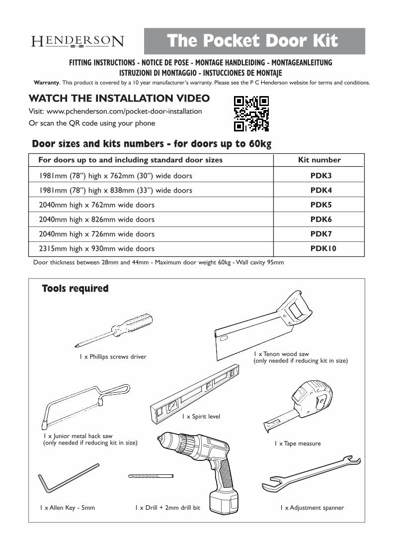
1981mm (78”) high x 762mm (30”) wide doors PDK3
1981mm (78”) high x 838mm (33”) wide doors PDK4
2040mm high x 762mm wide doors PDK5
2040mm high x 826mm wide doors PDK6
2040mm high x 726mm wide doors PDK7
2315mm high x 930mm wide doors PDK10
Door thickness between 28mm and 44mm - Maximum door weight 60kg - Wall cavity 95mm
Door sizes and kits numbers - for doors up to 60kgFor doors up to and including standard door sizes Kit number
Tools required
1 x Phillips screws driver 1 x Tenon wood saw (only needed if reducing kit in size)
1 x Junior metal hack saw(only needed if reducing kit in size)
1 x Spirit level
1 x Tape measure
1 x Drill + 2mm drill bit1 x Allen Key - 5mm 1 x Adjustment spanner
The Pocket Door Kit
WATCH THE INSTALLATION VIDEOVisit: www.pchenderson.com/pocket-door-installation
Or scan the QR code using your phone
FITTING INSTRUCTIONS - NOTICE DE POSE - MONTAGE HANDLEIDING - MONTAGEANLEITUNGISTRUZIONI DI MONTAGGIO - INSTUCCIONES DE MONTAJE
Warranty. This product is covered by a 10 year manufacturer’s warranty. Please see the P C Henderson website for terms and conditions.

Kit components
2 x Stud insert brackets
1 x Track, head andend brackets
4 x Uprights includingtimber infill
1 x Plastic guide
2 x Hanger apron plates
1 x Rubber stop
Screw A x 43/4” CSK. HD. Pozi(19mm)
Screw B x 81” BUT. HD. Pozi(25mm)
Screw C x 813/4” CSK. HD. Pozi(44mm)
Screw D x 145/8” BUT. HD. Pozi(16mm)
Screw E x 811/2” BUT. HD. Pozi(38mm)
Screws shown actual size
2 x Hangers
2 x Clipstops
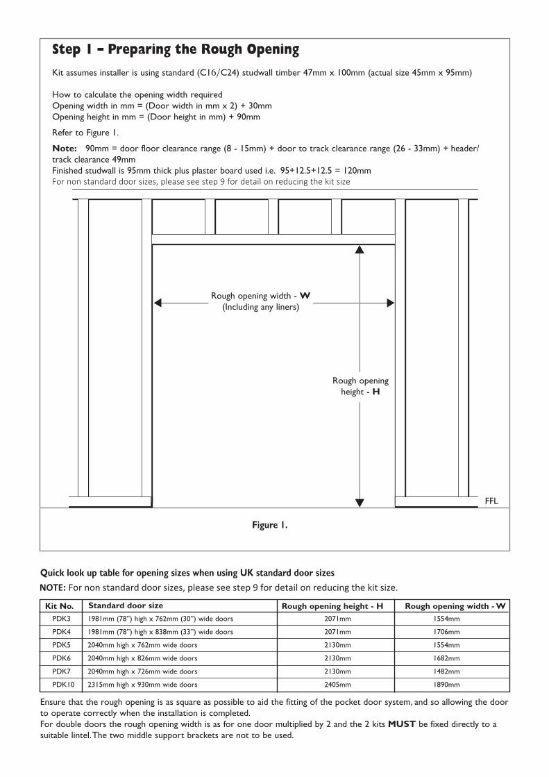
Rough opening width - W(Including any liners)
Rough openingheight - H
Step 1 – Preparing the Rough Opening
Kit assumes installer is using standard (C16/C24) studwall timber 47mm x 100mm (actual size 45mm x 95mm)
How to calculate the opening width requiredOpening width in mm = (Door width in mm x 2) + 30mmOpening height in mm = (Door height in mm) + 90mm
Refer to Figure 1.
Note: 90mm = door floor clearance range (8 - 15mm) + door to track clearance range (26 - 33mm) + header/track clearance 49mmFinished studwall is 95mm thick plus plaster board used i.e. 95+12.5+12.5 = 120mmFor non standard door sizes, please see step 9 for detail on reducing the kit size
Ensure that the rough opening is as square as possible to aid the fitting of the pocket door system, and so allowing the doorto operate correctly when the installation is completed.For double doors the rough opening width is as for one door multiplied by 2 and the 2 kits MUST be fixed directly to asuitable lintel.The two middle support brackets are not to be used.
Quick look up table for opening sizes when using UK standard door sizes
Figure 1.
PDK3 1981mm (78”) high x 762mm (30”) wide doors 2071mm 1554mm
PDK4 1981mm (78”) high x 838mm (33”) wide doors 2071mm 1706mm
PDK5 2040mm high x 762mm wide doors 2130mm 1554mm
PDK6 2040mm high x 826mm wide doors 2130mm 1682mm
PDK7 2040mm high x 726mm wide doors 2130mm 1482mm
PDK10 2315mm high x 930mm wide doors 2405mm 1890mm
Standard door sizeKit No. Rough opening width - WRough opening height - H
FFL
NOTE: For non standard door sizes, please see step 9 for detail on reducing the kit size.
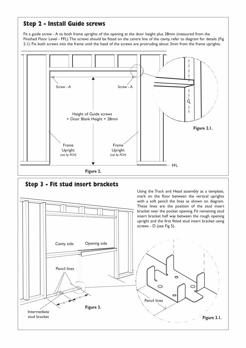
Fit a guide screw - A to both frame uprights of the opening at the door height plus 28mm (measured from theFinished Floor Level - FFL).The screws should be fitted on the centre line of the cavity, refer to diagram for details (Fig2.1). Fix both screws into the frame until the head of the screws are protruding about 3mm from the frame uprights.
Step 2 - Install Guide screws
Step 3 - Fit stud insert bracketsUsing the Track and Head assembly as a template,mark on the floor between the vertical uprightswith a soft pencil the lines as shown on diagram.These lines are the position of the stud insertbracket near the pocket opening. Fit remaining studinsert bracket half way between the rough openingupright and the first fitted stud insert bracket usingscrews - D (see Fig 5).
Height of Guide screws= Door Blank Height + 28mm
FrameUpright
(not by PCH)
FrameUpright
(not by PCH)
Figure 2.
Figure 3.=
=
Pencil lines
Pencil lines
Cavity side Opening side
FFL
Figure 2.1.
Figure 3.1.Intermediatestud bracket
Screw - A Screw - A
CL

Insert both hangers and clipstops into the track with the hanger ‘ears ‘ facing the clipstops at each end of the track,as shown in Fig. 4.1. Carefully lift the Head and Track assembly into the opening, then hook the metal brackets atboth ends of the assembly on to the protruding guide screws fitted earlier. Then rotate the assembly into the finalupright position (Fig.4).Whilst holding the assembly with one hand, screw the guide screws home at both ends.Thisshould hold the Head and Track assembly in position with friction. Do not let go of the assembly if it is not heldsecurely in place by the screws. Using a spirit level, check and correct the assembly ensuring it is level in all directions.Using screws B secure end brackets as indicated in Fig 4.2 & Fig 4.3.
Step 4 - Fitting the track & head assembly
Figure 4.
Screws - B Screw - D
Screw - A
Screws - D
Screw - A
Screws - B
Figure 4.2.
Figure 4.3.
Figure 4.1.‘Ear’ ‘Ear’
NOTE: For biparting door applications, discard the brackets for the opening side. Instead soffit fix this side of the track to the overhead lintel.
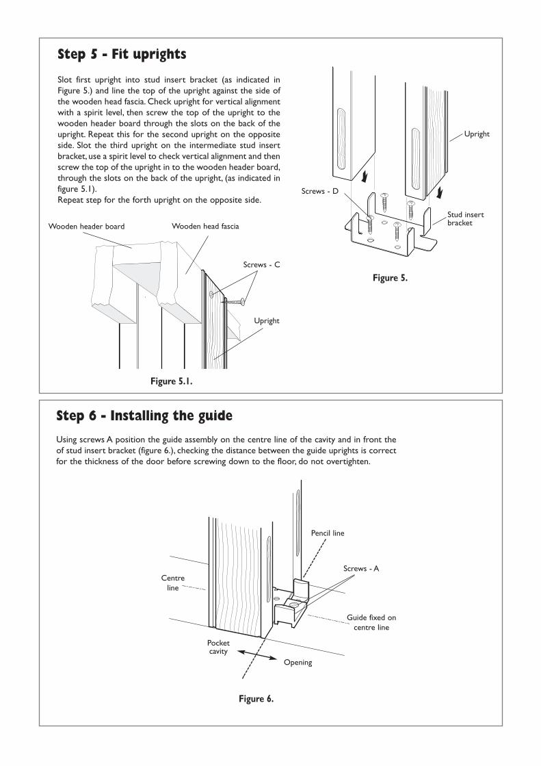
Slot first upright into stud insert bracket (as indicated in Figure 5.) and line the top of the upright against the side ofthe wooden head fascia. Check upright for vertical alignmentwith a spirit level, then screw the top of the upright to thewooden header board through the slots on the back of theupright. Repeat this for the second upright on the oppositeside. Slot the third upright on the intermediate stud insertbracket, use a spirit level to check vertical alignment and thenscrew the top of the upright in to the wooden header board,through the slots on the back of the upright, (as indicated infigure 5.1).Repeat step for the forth upright on the opposite side.
Using screws A position the guide assembly on the centre line of the cavity and in front theof stud insert bracket (figure 6.), checking the distance between the guide uprights is correctfor the thickness of the door before screwing down to the floor, do not overtighten.
Step 5 - Fit uprights
Step 6 - Installing the guide
Opening
Centreline
Pencil line
Screws - A
Screws - C
Screws - D
Guide fixed oncentre line
Pocketcavity
Figure 5.
Figure 5.1.
Figure 6.
Upright
Wooden head fasciaStud insertbracketWooden header board
Upright

Step 7 - Fitting the apron plates to the doorThe centre of the apron plates must be no closer to the corners of the door than 160mm (figure 7). Position the centres of the apron plates along the centre of the door blank. Using screws E fix both the hanger apron plates on to the top face of the door.
Step 8 – Hanging of the door
Move the hangers within the track to align with the hanger apron plates on the door. Carefully hook the door, via the apron plates, on to the bolt heads hanging beneath the hangers. The bolts heads must be firmly seated on the underside of the apron plates behind the apron plate ‘ears’.When in place adjust the door for height and alignment to the frame upright. When adjusted correctly screw down the lock nuts and tighten with a spanner.
> 160mm
Hanger apron plate
Centre of thedoor blank
Centre ofhanger
Figure 7.
Figure 8.
Screws - E
IMPORTANT: If installing our optional SOFT50 add on kit, please refer to Husky 50 Soft Stop fitting instructions for installation of apron plates and hanging of door.
Rubber Stop
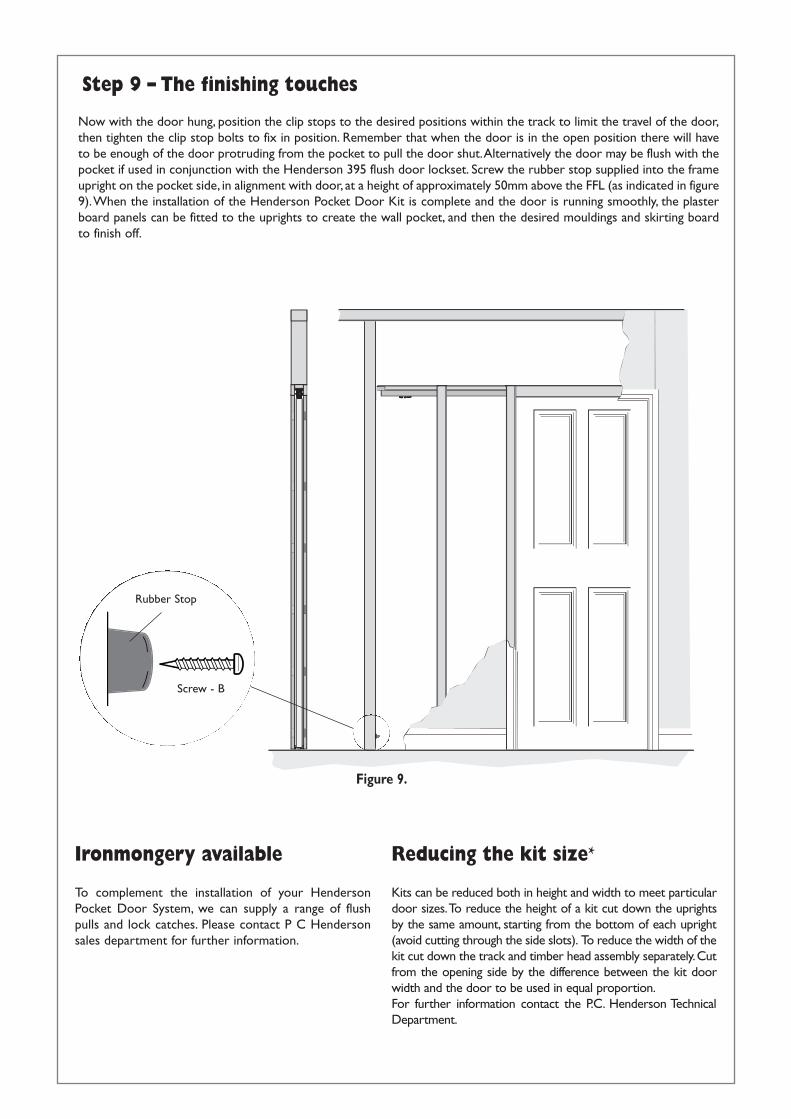
Now with the door hung, position the clip stops to the desired positions within the track to limit the travel of the door,then tighten the clip stop bolts to fix in position. Remember that when the door is in the open position there will haveto be enough of the door protruding from the pocket to pull the door shut.Alternatively the door may be flush with thepocket if used in conjunction with the Henderson 395 flush door lockset. Screw the rubber stop supplied into the frameupright on the pocket side, in alignment with door, at a height of approximately 50mm above the FFL (as indicated in figure9).When the installation of the Henderson Pocket Door Kit is complete and the door is running smoothly, the plasterboard panels can be fitted to the uprights to create the wall pocket, and then the desired mouldings and skirting boardto finish off.
To complement the installation of your HendersonPocket Door System, we can supply a range of flushpulls and lock catches. Please contact P C Hendersonsales department for further information.
Step 9 – The finishing touches
Ironmongery available
Figure 9.
Reducing the kit size*
Kits can be reduced both in height and width to meet particular door sizes.To reduce the height of a kit cut down the uprights by the same amount, starting from the bottom of each upright (avoid cutting through the side slots). To reduce the width of the kit cut down the track and timber head assembly separately. Cut from the opening side by the difference between the kit door width and the door to be used in equal proportion.For further information contact the P.C. Henderson Technical Department.
Screw - B
Part No: 666770 March 2020
Issue 17
12.5
32.0
32.0
12.5
Upright
Upright Upright
Baton
Baton
12.5
12.5 offset
Plasterboard
P in
k holes
th
Architrave
Plasterboard
Architrave
Plasterboard
Architrave
Plasterboard
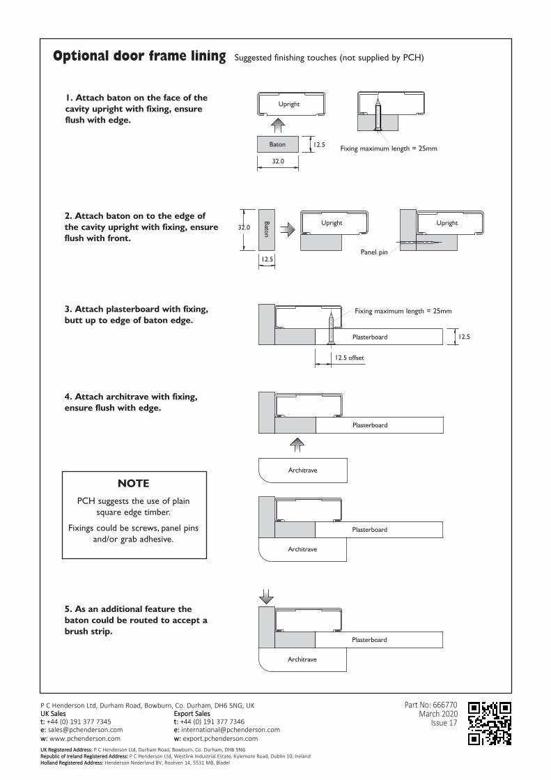
1. Attach baton on the face of thecavity upright with fixing, ensureflush with edge.
2. Attach baton on to the edge ofthe cavity upright with fixing, ensureflush with front.
3. Attach plasterboard with fixing,butt up to edge of baton edge.
4. Attach architrave with fixing,ensure flush with edge.
NOTE
PCH suggests the use of plainsquare edge timber.
Fixings could be screws, panel pinsand/or grab adhesive.
5. As an additional feature thebaton could be routed to accept abrush strip.
Fixing maximum length = 25mm
Optional door frame lining Suggested finishing touches (not supplied by PCH)
Fixing maximum length = 25mm
Panel pin
P C Henderson Ltd, Durham Road, Bowburn, Co. Durham, DH6 5NG, UKUK Sales t: +44 (0) 191 377 7345 e: [email protected] w: www.pchenderson.com
Export Salest: +44 (0) 191 377 7346e: [email protected]: export.pchenderson.com
UK Registered Address: P C Henderson Ltd, Durham Road, Bowburn, Co. Durham, DH6 5NGRepublic of Ireland Registered Address: P C Henderson Ltd, Westlink Industrial Estate, Kylemore Road, Dublin 10, Ireland Holland Registered Address: Henderson Nederland BV, Rootven 14, 5531 MB, Bladel
Recommended