1
Aerospace Vehicle Systems Institute
System and Software Integration VerificationSystem and Software Integration Verification
Texas Engineering Experiment Station
Aerospace Vehicle Systems InstituteAerospace Vehicle Systems Institute
The idea for this cooperative began in 1997 when Walt Gillette (now the 747X program manager Boeing Commercial Airplanes) met for a Texas A&M College of Engineering, Advisory Council meeting. B. Don. Russell, the A&M Associate Dean in charge of TEES, briefed Walt Gillette on a new research cooperative A&M had recently established for the petroleum industry. Walt was intrigued by the possibility of linking several industry members to do cooperative R&D under the protection of the National Cooperative Research and Production Act of 1993.
Walt Gillette wanted to improve the research for aircraft systems -- an area he believed was a problem in Boeing’s efforts to effectively design and build new commercial aircraft. These complex and expensive systems typically pace airplane programs.
Walt’s vision is to use AVSI as a vehicle to work with experts throughout the industry (Commercial and Defense), academia and elsewhere. Everyone will benefit by leveraging resources and developing an improved ability to work together.

2
Version Aerospace Vehicle Systems Institute
Slide 2
Project OverviewProject Overview
Overall Concept of OperationsDesign and production based on early and continuous integration (virtual => physical)Integrate, then build
ObjectiveShift architecting, design, and production activities to explicitly address integration issues early, reducing program execution risks, cycle time and cost
ApproachAdopt/develop “integration-based” software and system development processes with emphasis on integrating component-based, model-based and proof-based development
SSIV is a very ambitious, multi-year project to develop and demonstrate a “virtual integration” approach to product development that is likely to significantly affect how the aerospace industry handles embedded software-intensive systems in the future. The key concept is to address integration issues earlier and more comprehensively with improved consistent processes and tools.
3
Version Aerospace Vehicle Systems Institute
Slide 3
ParticipantsParticipants
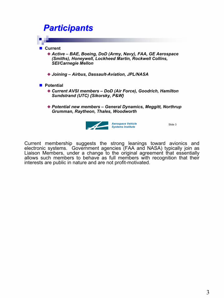
CurrentActive – BAE, Boeing, DoD (Army, Navy), FAA, GE Aerospace (Smiths), Honeywell, Lockheed Martin, Rockwell Collins, SEI/Carnegie Mellon
Joining – Airbus, Dassault-Aviation, JPL/NASA
PotentialCurrent AVSI members – DoD (Air Force), Goodrich, Hamilton Sundstrand (UTC) {Sikorsky, P&W}
Potential new members – General Dynamics, Meggitt, NorthrupGrumman, Raytheon, Thales, Woodworth
Current membership suggests the strong leanings toward avionics and electronic systems. Government agencies (FAA and NASA) typically join as Liaison Members, under a change to the original agreement that essentially allows such members to behave as full members with recognition that their interests are public in nature and are not profit-motivated.
Universities, consultants, research institutions, tool vendors and standards bodies are not mentioned on this slide, but are acknowledged to be absolutely necessary to the success of the project.

4
Expanded objectives from the current draft AFE 60

5
This chart is starts on the left with the repository of models and background data in the integrators repository. The “model bus” is both an internal conduit for developing an initial concept system and passing the “specs”(in the form of models) to a supplier. Each of the suppliers has their own repository of models and background (some of it proprietary) to merge with the integrator’s “specs” model and perhaps improve upon the system or subsystem. The project is designed to address thecolored (blue and green) parts of this process; it is hoped that the file sharing and configuration management can be handled with commercially available tools - not a part of this AVSI effort.
Aerospace Vehicle Systems Institute
Slide 5
Single Information and Relationships Single Information and Relationships RepositoryRepository
Integrate information and relationships in a single repository with a “model bus”
Better requirementsBetter integrationBetter communicationBetter consistency
Multi-Aspect Model Repository
“Model Bus”
File Sharing
Configuration Management
Supplier 1 IDE/Tools
Models
ModelsImport/Export
Supplier N IDE/Tools
Multi-Aspect Model Repository
Multi-Aspect Model Repository
Assembly Models Assembly Models
Components Assemblies Components Assemblies
“Model Bus”
System Integrator
Models
“Model Bus”
Configuration Management
Configuration Management
File Sharing File Sharing
...Models Models
IDEModeling
SimulationAnalysis
Virtual Integration
Multi-Aspect Model Repository
“Model Bus”
Components Assemblies
Configuration Management
File Sharing

6
Version Aerospace Vehicle Systems Institute
Slide 6
Overview of MultiOverview of Multi--Aspect Model Aspect Model Repository & Model Bus Repository & Model Bus
ModelRepository
MatLab
Esterel
TOPCASED
SCADE
SimuLink
Eclipse
Rhapsody
DOORS
OSATE
?
AADL
SysML
Requirements
Design
Verification
Integration/Deployment
In an earlier phase of the project AADL was chosen as the best starting point•Language features•Tool support (existing)•Extensibility support (AADL is good, not perfect)

7
Aerospace Vehicle Systems Institute
Slide 7
Modified Business ModelModified Business Model
System Integrator defines a new product using internal repository of virtual “parts”Specifications for virtual subcomponents sent to suppliers
A modification to the approach of developing complex systems is anticipated, placing the emphasis on model-based development. This chart illustrates the flow of specs (in model form) to suppliers and the return of component modules (CM) and system modules (SM)
back to be integrated in a virtual sense before any the product is produced.

8
Aerospace Vehicle Systems Institute
Slide 8
Modified Business Model Modified Business Model (continued)(continued)
Virtual parts returned for virtual integration into a virtual productCost savings realized by finding problems early on virtual parts
Once the virtual product is satisfactory, the actual product is developed
Cycle-time reduction realized since re-work on physical parts virtually eliminated
New SMNew SM
Repository
Parse &Process Modify Create
VirtuallyIntegrate
Existing CM/SM
Modified CM/SM
New CM/SM
CM/SM
IssuesNew SM
Repository
Parse &Process Modify Create
VirtuallyIntegrate
Existing CM/SM
Modified CM/SM
New CM/SM
CM/SM
IssuesNew SM
Repository
Parse &Process Modify Create
VirtuallyIntegrate
Existing CM/SM
Modified CM/SM
New CM/SM
CM/SM
IssuesNew SM
Repository
Parse &Process Modify Create
VirtuallyIntegrate
Existing CM/SM
Modified CM/SM
New CM/SM
CM/SM
Issues
New SM
VirtuallyIntegrate
New Product DefinitionNew SM
Issues
Specs
The benefits of such an model-based development are summarized on this chart - cost savings and cycle-time reduction are the overarching drivers in most complex system’s development. This chart underscores the feedback of the virtual integrations (both internal to the supplier and the OEM as well as between supplier and OEM).

9
Aerospace Vehicle Systems Institute
Slide 9
DeliverablesDeliverables
Component-Based Model FrameworkMulti-Aspect Model Repository Definition
Framework for Description of ComponentsRules for constructing and interconnecting componentsRules for property definitions supporting required (integration) analyses
Model Bus Definition for Consistent Model to Model Information Interchange
Virtual Integration Analyses Definitions CatalogParametric Process Definition for achieving Virtual Integration
Integrating Component-Based, Model-Based and Proof-Based Development
Pilot Project(s) Results and Lessons Learned

10
Version Aerospace Vehicle Systems Institute
Slide 10
Backup SlidesBackup Slides

11
Aerospace Vehicle Systems Institute
Slide 11
Transition to System and SW Engineering Transition to System and SW Engineering Integration Based on ComponentIntegration Based on Component--Based Based ArchitecturesArchitectures
SoS and Systems are Composed Primarily of Components
Modules that Encapsulate Both Data and Functionality, and Are Configurable at Run-TimeRequires accurate Modeling and Analysis of Properties, Relationships, Attributes, Associations, Interactions and Dependencies between Components
Control, Data, Timing, Sequencing, Synchronization, Interrupts, Performance, Latency, Jitter, Safety, Security, Reliability, Resources, Fault Tolerance, and other Quality FactorsComposable, Reusable Software Modules
Requires Two PerspectivesIndependent of the context in which they are usedDependent on the context in which they are used
Requires Component-Based Model Framework
B C DA
BLK DETCMP
S1 S2
Sensor
SSn
The sketch emphasizes that subsystems and systems are built up from components that are composable and reusable (based on both mathematical and empirical “proofs”. The models that allow this must be
consistent internally and must interface seamlessly in an integrated system.

12
Aerospace Vehicle Systems Institute
Slide 12
MultiMulti--Aspect Models for ModelAspect Models for Model--Centric DevelopmentCentric Development
Different models, modeling, simulation and analysis tools may be necessary for
Different propertiesDifferent users
Compatible modelling tools (open source or commercially available)
TOPCASEDAADLMATLAB/Simulink
This chart illustrates four types of multiple-aspect models used to carry out this scheme of consistent, not necessarily identical models. It is imperative to recognize both the essential differences (purpose, intent, and implementation) of models and the need for consistency in interfaces to allow the strengths of these different properties to be harnessed in an integrated system. Whatever the origin of the tool, this need for consistency and proof-testing is a strong driver for this concept to work.

13
The overall effort is broken down into eight work packages in the expectation that each work package is likely to have its own set of interested participants and one or more AFEs to complete their tasks. Some work packages will underpin or overarch the whole project - like WP0, which sets the management structure for this multifaceted project. Similarly, WP6 and WP7 are concerned with how to adapt infrastructure to this style of model-based development.
There are a lot of interactions between the subtasks of the different WPs. The work is planned to take 3+ years to perform, and is split into five phases: red label preparation, red label execution (initial pilot project), red label assessment and revision for black label (i.e., preparation), black label execution (final pilot project), black label validation (assessment) and production preparation. Red label execution will be performed mainly by researchers, and will use proof-of-concept prototype tools, some of which may just be paper procedures. Black-label execution will be performed mainly by program people and will use pre-production tools.
Recommended