UNIVERSITÀ DEGLI STUDI DI NAPOLI “FEDERICO II”
Scuola Politecnica e delle Scienze di Base
Department of Industrial Engineering – Aerospace Division
Doctoral Programme in Industrial Engineering
XXXI Cycle
Aeroelastic stability assessment of a CS-25 category aircraft
equipped with multi-modal wing morphing devices
Supervisors
Prof. Eng. Francesco Marulo
PhD Candidate
Prof. Eng. Leonardo Lecce Maria Chiara Noviello
Prof. Eng. Rosario Pecora
Prof. Eng. Francesco Amoroso
Co-supervisors
PhD Antonio Concilio
PhD Ignazio Dimino

3
Dediche
A mio marito Domenico e alla mia preziosa famiglia, per essere la certezza più
forte ed incrollabile che possa esistere. Nulla di tutto questo sarebbe stato possi-
bile senza la vostra costante presenza, dolce rifugio per me.
Alle mie speciali Amisisters, perché la distanza “spaziale” non ci ha mai impedito
di essere quotidianamente vicine. Grazie per i nostri “Ci amo”, per le parole di
conforto e di confronto e per i “A domani, bimbe”, come promessa che ci saremo
sempre l’una per l’altra. This is the Amisisters’ power!
Agli amici preziosi e ai miei parenti. Vi voglio bene!
4
Acknowledgments
First and foremost, I would like to thank the PhD School of the University of
Naples “Federico II” for giving me the opportunity to work on this interesting
research.
I wish to express my gratitude to Professor Leonardo Lecce for being an example
of “war machine” to follow.
Many thanks to my Professor Rosario Pecora for passing on strong passion and
enthusiasm for work to his students and… enthusiasm is contagious! I am ex-
tremely grateful for the technical assistance, patient supervision and excellent
guidance provided throughout my PhD.
I wish to thank my Professor Francesco Amoroso for being by my side during
these years. Constructive criticism during the discussion sections brought me to
grow and mature. Besides, I am very grateful for the empathy, humility and lis-
tening, rare gifts.
…This is why they are “Two Number One Professors”!
…And, last but not least, I want to thank the Italian Aerospace Research Center
for giving me this opportunity of professional growth, and for contributing to the
stimulating and exciting atmosphere in which I was able to conclude my studies.
I had the privilege of receiving authoritative scientific opinions of PhD Antonio
Concilio and to work under the invaluable supervision of PhD Ignazio Dimino,
whose teachings were fundamental to reach this goal.
5
Abstract
Morphing wing structures have the greatest ambition to dramatically improve
aircraft aerodynamic performance (less fuel consumption) and reduce aerody-
namic noise. Several studies in the literature have shown their potential for in-
creased aerodynamic efficiency across nearly all flight conditions, enhanced air-
craft maneuverability and control effectiveness, decreased takeoff/landing
length, reduced airframe noise, etc. However, despite a long heritage of research,
morphing wing technology has yet to be approved by the European Aviation
Safety Authority (EASA) for use in commercial aviation. Models and approaches
capable to predict the aeroelastic impact of a morphing wing still need to be ma-
tured to safely alter design and operation of future generations of aircraft. Addi-
tionally, a number of practical challenges remain to be addressed in the suitable
materials, systems reliability, safety and maintenance.
Due to the reduced stiffness, increased mass and increased Degree Of Free-
dom (DOF) with respect to conventional wings, these mechanical systems can
cause significant reduction of aircraft flutter margins. This aspect requires dedi-
cated aeroelastic assessments since the early stages of the design process of such
an innovative wing. Flutter boundaries predictions need sensitivity analyses to
evaluate bending/torsional stiffness and inertial distribution variability ranges of
the aircraft wing equipped with the morphing wing devices. In such a way, aero-
elastic assessments become fundamental to drive a balance between weight and
stiffness of the investigated adaptive systems. Furthermore, in pseudo rigid-body
mechanisms-based morphing structures, the inner kinematics is so important that
its faults may compromise the general aircraft-level functions. Similarly to the
demonstration means of safety compliance, commonly applied to aircraft control
surfaces, the novel functions resulting from the integration of adaptive devices
into flying aircraft thus impose a detailed examination of the associated risks.
In the framework of Clean Sky 2 Airgreen 2 project, the author provides ad-
vanced aeroelastic assessments of two adaptive devices enabling the camber
morphing of winglets and flaps, conceived for regional aircraft integration
(EASA CS-25 category). Segmented ribs architectures ensure the transition from
the baseline (or un-morphed) shape to the morphed ones, driven by embedded
electromechanical actuators. Some of the advantages resulting from the combi-
nation of the two aforementioned morphing systems are wing load control, lift-
over-drag ratio increase and root bending moment alleviation.
6
The aircraft aeroelastic model was generated by means of the proprietary
code SANDY 3.0 (see APPENDIX A – General Description of the Sandy code).
Then, the same code was adopted to solve the aeroelastic stability equations
through theoretical modes association in frequency domain. To carry out multi-
parametric flutter analyses (P-K continuation method), the actuation lines stiff-
ness and winglet/flap tabs inertial parameters were considered in combination
each other. Nominal operative conditions as well as systems malfunctioning or
failures were examined as analyses cases of the investigated morphing devices,
together with actuators free-play conditions. Proper design solutions were sug-
gested to guarantee flutter clearance in accordance with aircraft stability robust-
ness with respect to morphing systems integration, evaluated through a combina-
tion of “worst cases” simulating the mutual interaction among the adaptive sys-
tems.
The safety-driven design of the morphing wing devices required also a thor-
ough examination of the potential hazards resulting from operational faults in-
volving either the actuation chain, such as jamming, or the external interfaces,
such as loss of power supplies and control lanes, and both. The main goal was to
verify whether the morphing flap and winglet systems could comply with the
standard civil flight safety regulations and airworthiness requirements (EASA
CS25). More in detail, a comprehensive study of systems functions was firstly
qualitatively performed at both subsystem and aircraft levels to identify potential
design faults, maintenance and crew faults, as well as external environment risks.
The severity of the hazard effects was thus determined and then ranked in specific
classes, indicative of the maximum tolerable probability of occurrence for a spe-
cific event, resulting in safety design objectives. Fault trees were finally produced
to assess the compliance of the system architectures to the quantitative safety
requirements resulting from the FHAs.
7
Index
1 Introduction ................................................................................................ 15
1.1 General ................................................................................................ 15
1.2 Motivation of work .............................................................................. 18
1.3 Objectives ............................................................................................ 20
1.4 Organization of the thesis .................................................................... 21
1.5 Author’s published works ................................................................... 22
2 State of the art on morphing structures ....................................................... 25
2.1 Adaptive wings .................................................................................... 25
2.2 Clean Sky 2 Airgreen 2 Project ........................................................... 29
2.3 Overview on AG2 morphing devices .................................................. 30
3 Morphing wing devices .............................................................................. 33
3.1 Morphing flap ...................................................................................... 33
3.1.1 Scope and reference geometries ................................................... 33
3.1.2 Aerodynamics and Benefits ......................................................... 34
3.1.3 Morphing flap architecture .......................................................... 36
3.2 Morphing winglet ................................................................................ 40
3.2.1 Scope and reference geometries ................................................... 40
3.2.2 Aerodynamics and Benefits ......................................................... 41
3.2.3 Morphing winglet architecture ..................................................... 42
4 Aeroelasticity .............................................................................................. 45
4.1 Introduction ......................................................................................... 45
4.1.1 Structural Model .......................................................................... 45
4.1.2 Inertial Model ............................................................................... 46
4.1.3 Aerodynamic Model .................................................................... 46
4.2 Aeroelastic stability equations ............................................................ 46
4.2.1 Generalized Aerodynamic Forces ................................................ 46
4.2.2 Impedance matrix ......................................................................... 48
4.3 Classification of the methods for flutter evaluation ............................ 50
4.3.1 K methods .................................................................................... 51
8
4.3.2 PK methods .................................................................................. 54
4.4 Aerodynamic forces approximation .................................................... 58
4.4.1 P method ...................................................................................... 59
4.5 Harmonic Balance Method .................................................................. 61
5 Aeroelasticity of morphing devices ............................................................ 65
5.1 Dynamic Model ................................................................................... 65
5.1.1 Structural Model .......................................................................... 65
5.1.2 Inertial Model ............................................................................... 73
5.2 Aerodynamic and Interpolation Model ............................................... 74
5.3 Flutter Analyses ................................................................................... 75
5.3.1 Trade-off flutter analysis on flap tabs .......................................... 76
5.3.2 Trade-off flutter analysis on winglet tabs combined with flap tabs
86
5.3.3 Free-Play Analyses Results, Harmonic Balance Method .......... 103
6 Morphing Wing – Safety and Reliability issues ....................................... 106
6.1 Introduction ....................................................................................... 106
6.2 Safety Analysis: general approach .................................................... 107
6.2.1 Functional Hazard Assessment - FHA ....................................... 111
6.2.2 System Safety Assessment—Fault Tree Analysis ..................... 113
6.2.3 Active Versus Hidden Failures .................................................. 114
6.2.4 On safety factor .......................................................................... 115
6.3 Morphing devices: Aircraft level functions ...................................... 115
6.4 Morphing flap .................................................................................... 117
6.5 Morphing winglet .............................................................................. 122
6.6 Integrated Safety Analyses ................................................................ 128
7 Conclusions and Future Works ................................................................. 136
APPENDIX A – General Description of the Sandy code ................................ 138
APPENDIX B - CS 23.629 Flutter .................................................................. 140
References ........................................................................................................ 146
9
Nomenclature
1D Mono-Dimensional
2D Bi-Dimensional
2MMF Bi-Modal Morphing Flap
3D Three-Dimensional
3MMF Three-Modal Morphing Flap
A/C Aircraft
AIC Aerodynamic Influence Coefficients
b Span Length
Bi i-th Block Of The Rib
CL Lift Coefficient
CL_MAX Maximum Lift Coefficient
CP Pressure Coefficient
Cr Root Chord Length
Ct Tip Chord Length
D Drag
DLM Doublet Lattice Method
DMIG Direct Matrix Input At Grids
DOF Degree Of Freedom
EA Normal Force Stiffness
ECU Electronic Control Unit
EImin(max) Minimum (Maximum) Bending Stiffness
FDAL Functional Design Assurance Level
FE(M) Finite Element (Model)
FHA Fault And Hazard Assessment
FT(A) Fault Tree (Analysis)
GAF Generalized Aerodynamic Forces
Gij Participation Factor Mode I With Respect To Mode J
GJ Torsional Stiffness
GRA Green Regional Aircraft
GVT Ground Vibration Test
HD Harmonic Drive
K Actuators Stiffness
Keq Actuators Equivalent Stiffness
L/D Aerodynamic Efficiency
L Lift
LVDT Linear Variable Displacement Transducer
MAC Mean Aerodynamic Chord
MAV Micro Air Vehicle
MT Maintenance Time
MWL Morphing Winglet
MZFW Maximum Zero Fuel Weight
NS Navier-Stokes
PSSA Preliminary System Safety Assessment
RBE Rigid Body Element
SSA System Safety Assessment
TP90 90-Pax Turboprop

10
TRL Technology Readiness Level
UAV Unmanned Aircraft Vehicle
VD Dive Speed
VF Flutter Speed
11
List of Figures
Fig. 1: Example of flutter shapes in case of movable surfaces .......................... 17
Fig. 2: Wright-Brothers aircraft: a detail of wing warping, [19] ....................... 25
Fig. 3: Morphing wing concept: (a) NASA Dryden inflatable wing during flight
testing [24]; and (b) telescopic wing concept [25] ............................................. 27
Fig. 4: (a) Lockheed Martin folding-wing UAV concept, [26], and (b) NextGen
Batwing morphing UAV concept, [27] .............................................................. 27
Fig. 5: MAV roll control achieved via wing warping, [28] ............................... 28
Fig. 6: Drooped Nose structure, [30] ................................................................. 31
Fig. 7: Morphing flap architecture, top view ..................................................... 32
Fig. 8: Morphing winglet Finite Element Model (left) and architecture (right),
[31] ..................................................................................................................... 32
Fig. 9: Morphing flap investigation domain, [32] .............................................. 34
Fig. 10: Aerodynamic pressure uniform distribution on tabs surfaces, [32] ..... 35
Fig. 11: Morphing flap articulated rib, [32] ....................................................... 36
Fig. 12: Morphing flap target shape, mode 1, [32] ............................................ 36
Fig. 13:B1/B2 gear ratio trend, [32] ................................................................... 37
Fig. 14: Morphing flap preliminary design assumption, [32] ............................ 38
Fig. 15: Section view of through shaft actuation concept, [32] ......................... 39
Fig. 16: Wireframe view of through shaft actuation concept, [32] .................... 39
Fig. 17: Movable surfaces of the morphing winglet, [38] ................................. 40
Fig. 18: Upper (on left) and lower (right) deflection, [38] ................................ 41
Fig. 19: Example of Cp distribution on the morphing winglet for negative
deflections of both the upper and lower surfaces, [38] ...................................... 41
Fig. 20: Detail of the morphing winglet architecture, [38]. ............................... 42
Fig. 21: Detail of the morphing winglet architecture, [38]. ............................... 43
Fig. 21: EMA actuators: a) sectional and b) external view, [37] ....................... 43
Fig. 22: Aeroelasticity conceptual scheme, [40] ................................................ 45
Fig. 23: Aerodynamic Lattice, [40] .................................................................... 47
Fig. 24: Example of V-g plot in case of two modes only, K-Method, [40] ....... 52
Fig. 25: Non –linearity in a linear system, [40] ................................................. 61
Fig. 26: LH morphing flap preliminary Finite Element Model developed by
UniNa, [31] ........................................................................................................ 66
Fig. 27: LH morphing winglet preliminary Finite Element Model developed by
CIRA, [31] ......................................................................................................... 66
Fig. 28: Elastic axis convergence parameter, [31] ............................................. 68
Fig. 29: Logical Flow for the stiffness properties evaluation ............................ 69
Fig. 30: Example of load case applied for GJ evaluation, [31] .......................... 70
Fig. 31: Flap tabs stiffness properties ................................................................ 71
Fig. 32: Winglet tabs stiffness properties .......................................................... 72
Fig. 33: TP90 Dynamic model in Sandy environment (ref. axes in meters), [31]
............................................................................................................................ 74
12
Fig. 34:TP90 aerodynamic model in Sandy environment (ref. axes in meters),
[31] ..................................................................................................................... 74
Fig. 35: TP90 Aeroelastic model in Sandy Environment (ref. axes in meters),
[31] ..................................................................................................................... 75
Fig. 36: Trade- off analyses parameters on flap tabs ......................................... 77
Fig. 37: First trade-off Carpet Plot ..................................................................... 77
Fig. 38: Flutter mode 31 - Symmetric wing tip/winglet bending ...................... 78
Fig. 39: Flutter Mode 37 - Symmetric outer wing torsion ................................. 79
Fig. 40: Flutter Mode 38 - Anti-symmetric outer wing torsion ......................... 79
Fig. 41: Participation Factors, Mode 31 [31] ..................................................... 80
Fig. 42: Participation factors, Mode 37, [31] ..................................................... 81
Fig. 43: Participation factors, Mode 38, [31] ..................................................... 81
Fig. 44: Minimum modal flutter association ...................................................... 82
Fig. 45: Minimum flutter speed as function of flap tabs degree of balancing, for
a fixed value of tabs actuation line stiffness ...................................................... 84
Fig. 46: Minimum flutter speed as function of flap tabs actuation line stiffness,
30 % Degree of Balancing ................................................................................. 85
Fig. 47: Flutter speed as function of tabs actuation line stiffness, 40% Degree of
Balancing ........................................................................................................... 85
Fig. 48: Trade-off analysis on winglet tabs combined with flap tabs in locked
commands, carpet plot [31] ................................................................................ 87
Fig. 49: Mode 31: anti-symmetric wing tip torsion/winglet bending ................ 88
Fig. 50: Mode 32: Symmetric outer wing torsion/winglet bending ................... 88
Fig. 51: Anti-symmetric outer wing torsion/winglet bending ........................... 89
Fig. 52: Example of V-g plot on winglets tabs trade-off analysis, [31] ............. 90
Fig. 53: Mode 31, Participation factors ............................................................. 91
Fig. 54: Mode 32, Participation factors ............................................................. 91
Fig. 55: M33, Participation factors .................................................................... 91
Fig. 56: Minimum modal association, winglets tabs flutter modes ................... 92
Fig. 57: Minimum flutter speed VS winglet tabs degree of balancing in two
inertial configurations (nominal and 30% increase of the nominal mass) ......... 93
Fig. 58: Minimum flutter speed as function of tabs degree of balancing. ......... 94
Fig. 59: Flutter speed trend as a function of plug stiffness gain factor .............. 95
Fig. 60: Flutter speed trend as a function of tabs massbalancing, F DMIK = 5 96
Fig. 61: Winglets tabs mass gain factor as function of flutter speed, with plug
stiffness gain factor equal to 5 ........................................................................... 97
Fig. 62: Winglets tabs mass gain factor as function of flutter speed, with plug
stiffness gain factor equal to 2 ........................................................................... 97
Fig. 63: Winglet bending mode (M32), in case of no plug stiffness gain factor
and 100% tabs mass ........................................................................................... 99
Fig. 64: V-g plot in the condition A ................................................................. 100
Fig. 65: – Simmetric wing torsional-bending mode in case of F DMIK=2 and
wlet tabs mass 70% .......................................................................................... 101
Fig. 66: V-g plot in the condition B ................................................................. 102
13
Fig. 67: Load-Deflection non-linear law ......................................................... 103
Fig. 68: Winglet tabs actuators equivalent stiffness Vs tabs oscillation
amplitude .......................................................................................................... 104
Fig. 69: Flutter analyses results in case of tabs actuators free-play ................. 105
Fig. 70: Example of electromechanical Actuator fault tree with failure rates per
hour .................................................................................................................. 107
Fig. 71: CS-25 safety assessment process overview ........................................ 109
Fig. 72: Relationship between Probability and Severity of Failure Condition
Effects, [2] ........................................................................................................ 110
Fig. 73: Required probability figures versus safety classification ................... 113
Fig. 74: Safety factor vs probability in failure condition ................................. 115
Fig. 75: Morphing Flap High Lift Generation Fault Tree Analysis ................. 121
Fig. 76: Morphing flap Undetected Inadvertent tab control at high speed Fault
Tree Analysis ................................................................................................... 121
Fig. 77: Morphing winglet - Uncontrolled dynamic motion (left or right) Fault
Tree Analysis ................................................................................................... 127
Fig. 78: Destruction of wing FTA .................................................................... 127
Fig. 79: LH winglet tabs actuators and gear ratio DMIG scheme, Baseline
configuration .................................................................................................... 128
Fig. 80: CASE 1 – LH upper link isolated failure ........................................... 129
Fig. 81: CASE 2 – LH lower link isolated failure ........................................... 130
Fig. 82: CASE 3: LH upper tab actuator isolated failure ................................. 130
Fig. 83: CASE 4 - LH lower tab actuator isolated failure ............................... 131
Fig. 84: CASE 5 – LH upper actuator and link combined failure ................... 132
Fig. 85: CASE 6 – LH lower actuator and link combined failure ................... 132
Fig. 86: CASE 7 – LH upper actuator and lower link combined failure ......... 133
Fig. 87: CASE 8 – LH lower tab and upper link combined failure ................. 134
Fig. 88: Example of V-g plot ........................................................................... 144
14
List of Tables
Table 1: Aerodynamic values in limit load condition, [32] ............................... 35
Table 2: Winglet materials mechanical properties ............................................. 44
Table 3: Massbalancing values of morphing flap tabs ....................................... 83
Table 4: Massbalancing solutions: impact on winglet weight ........................... 86
Table 5: Winglet weight in case of 130% DoB ................................................. 94
Table 6: Winglet weight in case of doublet stiffness of plug and 30% saving of
tabs mass ............................................................................................................ 98
Table 7: Flutter Results of Condition A ............................................................. 98
Table 8: Flutter Results of Condition B ........................................................... 100
Table 9: Equivalent stiffness of winglet tabs actuation line ............................ 104
Table 10: Aircraft functions impacted by Morphing Wing concept, [43]-[44]116
Table 11: Aircraft functions impacted by Morphing Flap concept, [45] ......... 119
Table 12: Potential failures identified in morphing winglet preliminary FHA
.......................................................................................................................... 123
Table 13: Aircraft functions impacted by Morphing Winglet concept ............ 125
Table 14: Failure scenarios investigated for morphing winglet ....................... 129
Table 15: Flutter analyses results in failure scenarios investigated for morphing
winglet .............................................................................................................. 134
15
1 Introduction
1.1 General
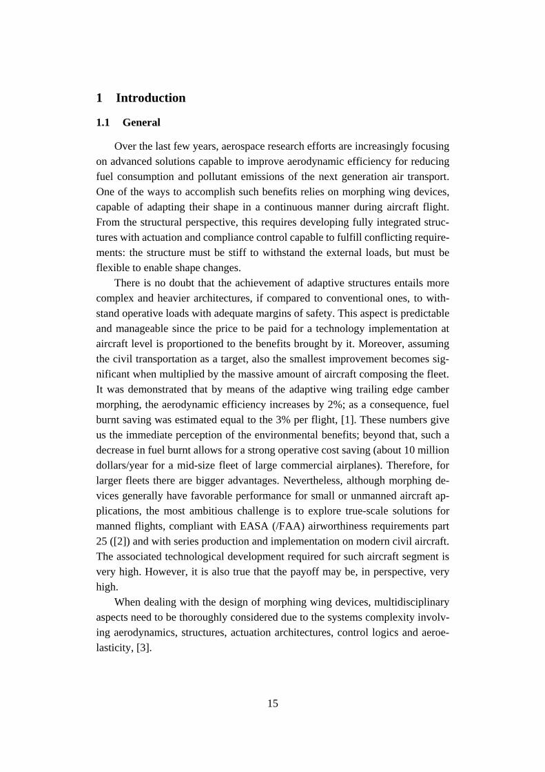
Over the last few years, aerospace research efforts are increasingly focusing
on advanced solutions capable to improve aerodynamic efficiency for reducing
fuel consumption and pollutant emissions of the next generation air transport.
One of the ways to accomplish such benefits relies on morphing wing devices,
capable of adapting their shape in a continuous manner during aircraft flight.
From the structural perspective, this requires developing fully integrated struc-
tures with actuation and compliance control capable to fulfill conflicting require-
ments: the structure must be stiff to withstand the external loads, but must be
flexible to enable shape changes.
There is no doubt that the achievement of adaptive structures entails more
complex and heavier architectures, if compared to conventional ones, to with-
stand operative loads with adequate margins of safety. This aspect is predictable
and manageable since the price to be paid for a technology implementation at
aircraft level is proportioned to the benefits brought by it. Moreover, assuming
the civil transportation as a target, also the smallest improvement becomes sig-
nificant when multiplied by the massive amount of aircraft composing the fleet.
It was demonstrated that by means of the adaptive wing trailing edge camber
morphing, the aerodynamic efficiency increases by 2%; as a consequence, fuel
burnt saving was estimated equal to the 3% per flight, [1]. These numbers give
us the immediate perception of the environmental benefits; beyond that, such a
decrease in fuel burnt allows for a strong operative cost saving (about 10 million
dollars/year for a mid-size fleet of large commercial airplanes). Therefore, for
larger fleets there are bigger advantages. Nevertheless, although morphing de-
vices generally have favorable performance for small or unmanned aircraft ap-
plications, the most ambitious challenge is to explore true-scale solutions for
manned flights, compliant with EASA (/FAA) airworthiness requirements part
25 ([2]) and with series production and implementation on modern civil aircraft.
The associated technological development required for such aircraft segment is
very high. However, it is also true that the payoff may be, in perspective, very
high.
When dealing with the design of morphing wing devices, multidisciplinary
aspects need to be thoroughly considered due to the systems complexity involv-
ing aerodynamics, structures, actuation architectures, control logics and aeroe-
lasticity, [3].
16
Speaking about the latter, it regards the effect of aerodynamic forces on elas-
tic bodies, such as aircraft wings or compressor blades, which fully depend on
the deformed shape of the structure in the flow. One of the most serious aeroe-
lastic phenomena is the instability of a structure in a flow. For a given initial
shape of an elastic structure, the aerodynamic force increases rapidly with the
flow speed, and there may exist a critical flow speed at which the structure be-
comes unstable. Such instability may cause excessive deformation, and may lead
to the destruction of the structure. The interplay of aerodynamic, elastic, and in-
ertia forces is usually referred to as flutter or dynamic aeroelastic instability. If a
structure is excited with external forces in the absence of flow, the structure will
oscillate and the oscillation will damp gradually. With the presence of a flow, the
rate of damping of the oscillation may increase at low flow speeds and on in-
creasing the flow speed, a point will be reached at which the damping rapidly
decreases, and the oscillation can just maintain itself with a steady amplitude.
This speed is known as the critical flutter speed, and at speed of flow just above
that critical speed, a great violent oscillation will be triggered, at any small dis-
turbance to the structure, and the structure is said to flutter.
There are many definitions of flutter within the literature. Some of the most
recognized are [4] – [5]:
• Aeroelastic and self-excited vibration, in which the external source
of energy is the air stream;
• Aerodynamic self-exited oscillations;
• Self-sustained oscillatory instability;
• Cyclic and high frequency oscillation of the airfoil caused by a strug-
gle between the aerodynamic forces and the stiffness of the surfaces;
• Dynamic instability of an elastic body in an airstream produced by
aerodynamic forces which result from the deflection of the elastic
body from its undeformed state;
• Dynamic aeroelastic instability;
• Dynamic instability occurring in an aircraft in flight at a certain speed
where the elasticity of the structure plays an essential part in the in-
stability;
• Self-excited or unstable oscillation arising out of the simultaneous
action of elastic, inertia and aerodynamic lift forces upon a mass or a
system of masses;
17
• Oscillatory instability arising from the condition where one degree of
freedom is driven at resonance by a second degree of freedom, both
oscillating at the same frequency;
• Unstable divergent motion or vibration caused by the aerodynamic
forces;
• A condition at which the total damping of a system under the action
of air forces (and the inertia, elastic, and friction forces) changes from
positive to negative, at flutter speed the damping is zero so that sus-
tained oscillations would occur.
The parametric study of flutter is a crucial step of the aeroelastic assessment.
Aeroelastic stability equations can be solved numerically by adopting different
methods, detailed in Section 4. Typically, the outputs of flutter analyses are con-
densed in the so-called V-g plot, showing the trend of flutter modes speed as a
function of the modal damping (further details are provided in APPENDIX B -
CS 23.629 Flutter).
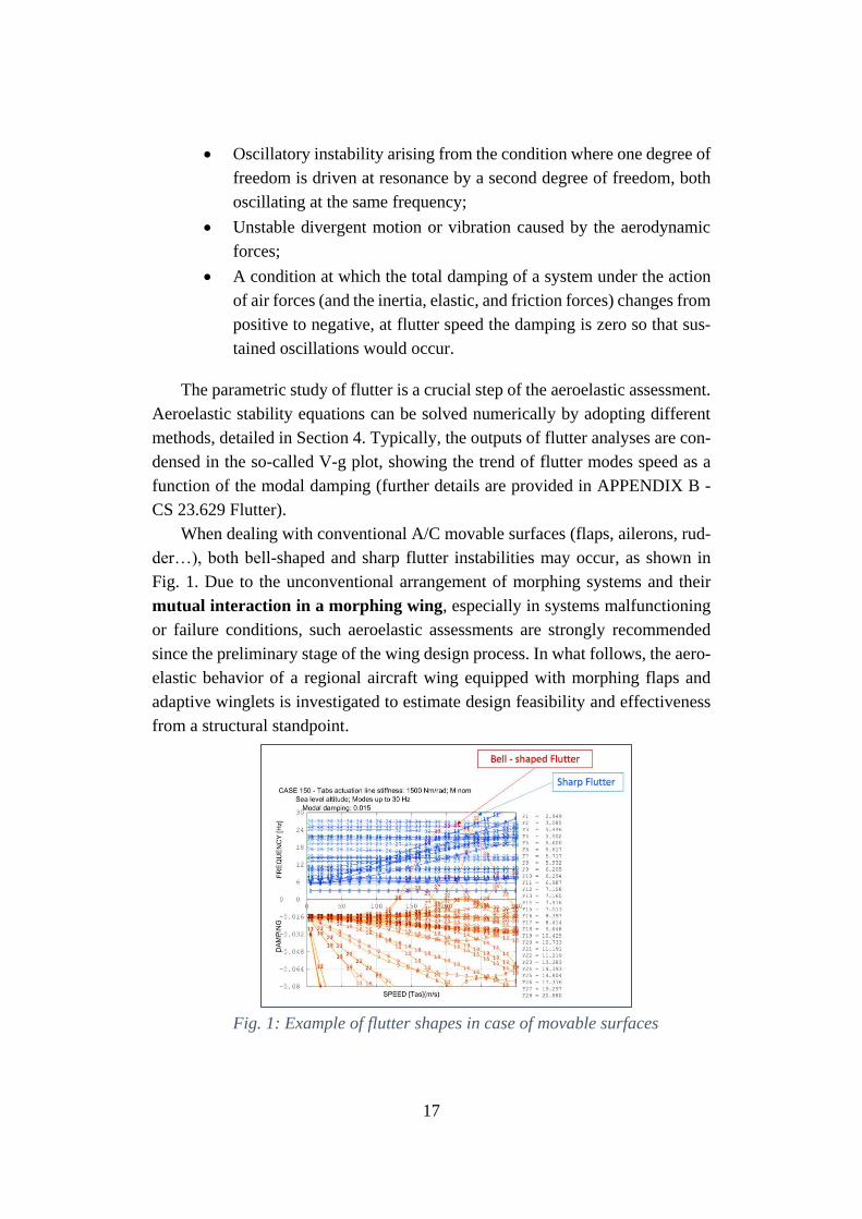
When dealing with conventional A/C movable surfaces (flaps, ailerons, rud-
der…), both bell-shaped and sharp flutter instabilities may occur, as shown in
Fig. 1. Due to the unconventional arrangement of morphing systems and their
mutual interaction in a morphing wing, especially in systems malfunctioning
or failure conditions, such aeroelastic assessments are strongly recommended
since the preliminary stage of the wing design process. In what follows, the aero-
elastic behavior of a regional aircraft wing equipped with morphing flaps and
adaptive winglets is investigated to estimate design feasibility and effectiveness
from a structural standpoint.
Fig. 1: Example of flutter shapes in case of movable surfaces
18
1.2 Motivation of work
In general, morphing structures can change their geometry in order to achieve
a wide range of performance, [6]. In case of morphing aircraft, such goals include
alleviating drag, or altering airfoil lift.
Conventional engineered structures, such as aircraft wings, are conceived to
exhibit a desired aeroelastic response. This allows for obtaining small operational
deflections, and hence well-defined aerodynamic and aeroelastic loading. There-
fore, structural engineers feel certain that a wing with the required mass and stiff-
ness, and with the shape set out by aerodynamics engineers, will allow achieving
the predicted lift and drag properties. Well-developed aircraft systems sizing
methods apply, speeding up the early stages of the design process, [7]. It is not
possible to state the same for the design of morphing wing structures. The large
changes in performance achievable have an inevitable impact in terms of the
mass, stiffness and actuation requirements. This complicates the systems sizing,
since it is not immediate defining which morphing configuration should dominate
the design. In the literature, these difficulties are overcome by reducing the prob-
lem to its constituent components. These involve designing the aircraft structure
ensuring the target morphing shapes, or performing aerodynamic optimization to
find the optimum shapes that wings should morph between. A further step regards
the interaction between structure and aerodynamics, to ensure aeroelastic stabil-
ity during flight. The strategy of splitting the design problem into distinct disci-
plines has enabled production of a great amount of morphing aircraft concepts.
However, it should be noted that a more comprehensive approach could empha-
size the potential structural improvements in terms of weight and number of com-
ponents while maintaining the requested aerodynamic benefits. A brief summary
of these design methods is recalled below to highlight the difficulties of an inte-
grated-design approach.
• Structural optimization solves a material distribution problem sub-
ject to constraints, [8]. For the majority of structural optimization
problems, the aim is to conceive a structure which can support a
given load, although achieving other characteristics as, for example,
minimum total weight, optimal center of mass location, or meeting a
given density requirement. Typically, the optimization problem is
solved through parametrization schemes, such as sizing, material,
shape and topology optimization [9] - [10] - [11] - [12].
19
• Aerodynamic optimization is the process of finding the geometry
providing the best aerodynamic properties. A typical problem opti-
mizes a set of decision variables governing the airfoil shape through
a predefined parameterization scheme. The new shape’s aerody-
namic properties are then evaluated, and used to update the decision
variables, until the geometry has converged to an optimal solution
[13] - [14] - [15]. Aerodynamic optimization of morphing structures
requires replacement of the shape parameterization by a structural
model with optimizer-controlled actuation, [16]. The sensitivity
analysis can then be performed to investigate the result of small per-
turbations in the actuation variables on the resulting structure, and
subsequent flow properties. Computationally-efficient structural
models are typically implemented, to reduce the expense of predict-
ing structural displacements, [17]. This reduces the computational
requirements of the sensitivity analysis, which are often dominated
by aerodynamic calculations. A benefit of this type of analysis is that
the aeroelasticity of the problem can be readily evaluated [18]; a
summary of which follows below.
• Aeroelastic tailoring regards the effect of interaction between the
aerodynamic loads due to normal operating flight and the elastic de-
formation of the aircraft structure [18]. It can have a huge impact on
flight performance: stability, handling and structural load distribu-
tion can all be involved. When dealing with the design of morphing
wing structures, due to the augmented Degree Of Freedom and
weight with respect to conventional architectures, it is typically re-
quired to increase their compliance to enable shape changes. This
can make them susceptible to large deformations due to aerodynamic
loads, which in turn can influence aircraft stability; flutter boundaries
can be reduced significantly with respect to rigid airfoils. This indi-
cates that introducing compliance can leads to reduced stability.
All the aforementioned topics drove toward the scope of the present thesis.
More in detail, to enable effective aeroelastic wing shape control, a more com-
prehensive design approach was developed to properly predict flutter boundaries
and the related sensitivity by changing bending/torsional stiffness and mass dis-
tribution.
20
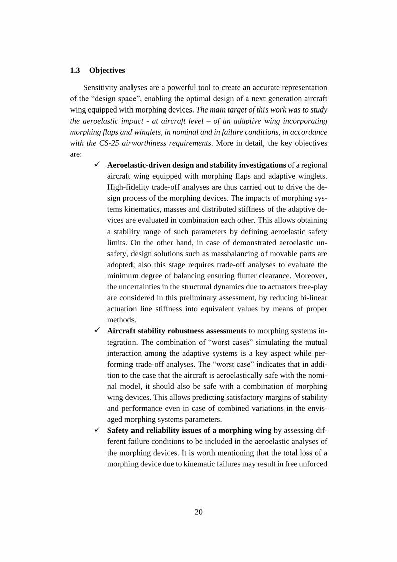
1.3 Objectives
Sensitivity analyses are a powerful tool to create an accurate representation
of the “design space”, enabling the optimal design of a next generation aircraft
wing equipped with morphing devices. The main target of this work was to study
the aeroelastic impact - at aircraft level – of an adaptive wing incorporating
morphing flaps and winglets, in nominal and in failure conditions, in accordance
with the CS-25 airworthiness requirements. More in detail, the key objectives
are:
✓ Aeroelastic-driven design and stability investigations of a regional
aircraft wing equipped with morphing flaps and adaptive winglets.
High-fidelity trade-off analyses are thus carried out to drive the de-
sign process of the morphing devices. The impacts of morphing sys-
tems kinematics, masses and distributed stiffness of the adaptive de-
vices are evaluated in combination each other. This allows obtaining
a stability range of such parameters by defining aeroelastic safety
limits. On the other hand, in case of demonstrated aeroelastic un-
safety, design solutions such as massbalancing of movable parts are
adopted; also this stage requires trade-off analyses to evaluate the
minimum degree of balancing ensuring flutter clearance. Moreover,
the uncertainties in the structural dynamics due to actuators free-play
are considered in this preliminary assessment, by reducing bi-linear
actuation line stiffness into equivalent values by means of proper
methods.
✓ Aircraft stability robustness assessments to morphing systems in-
tegration. The combination of “worst cases” simulating the mutual
interaction among the adaptive systems is a key aspect while per-
forming trade-off analyses. The “worst case” indicates that in addi-
tion to the case that the aircraft is aeroelastically safe with the nomi-
nal model, it should also be safe with a combination of morphing
wing devices. This allows predicting satisfactory margins of stability
and performance even in case of combined variations in the envis-
aged morphing systems parameters.
✓ Safety and reliability issues of a morphing wing by assessing dif-
ferent failure conditions to be included in the aeroelastic analyses of
the morphing devices. It is worth mentioning that the total loss of a
morphing device due to kinematic failures may result in free unforced
21
oscillations which may potential lead to flutter phenomena. Failure
scenarios for the morphing wing devices were thus investigated by
reproducing the rupture of primary hinges and/or actuation links of
the movable parts.
Multi-parametric analyses results were thus used to identify and validate
proper “aeroelastically safe” design solutions with respect to morphing surfaces.
For that purpose, the proprietary code SANDY 3.0 code was adopted to solve the
aeroelastic stability equations through theoretical modes association in frequency
domain. Moreover, safety activities were performed to verify whether morphing
flap and winglet concepts could comply with the standard civil flight safety reg-
ulations and airworthiness requirements. Fault and Hazard Analysis (FHA) was
used to assess the severity of properly identified failure conditions and then allo-
cate safety requirements. Fault Tree modelling technique was used to verify the
compliance of the system architectures to the quantitative safety requirements
resulting from the FHAs.
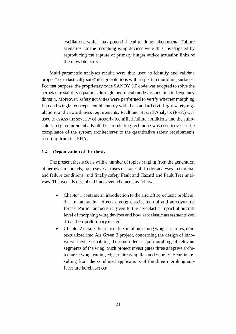
1.4 Organization of the thesis
The present thesis deals with a number of topics ranging from the generation
of aeroelastic models, up to several cases of trade-off flutter analyses in nominal
and failure conditions, and finally safety Fault and Hazard and Fault Tree anal-
yses. The work is organized into seven chapters, as follows:
• Chapter 1 contains an introduction to the aircraft aeroelastic problem,
due to interaction effects among elastic, inertial and aerodynamic
forces. Particular focus is given to the aeroelastic impact at aircraft
level of morphing wing devices and how aeroelastic assessments can
drive their preliminary design.
• Chapter 2 details the state of the art of morphing wing structures, con-
textualized into Air Green 2 project, concerning the design of inno-
vative devices enabling the controlled shape morphing of relevant
segments of the wing. Such project investigates three adaptive archi-
tectures: wing leading edge, outer wing flap and winglet. Benefits re-
sulting from the combined applications of the three morphing sur-
faces are herein set out.
22
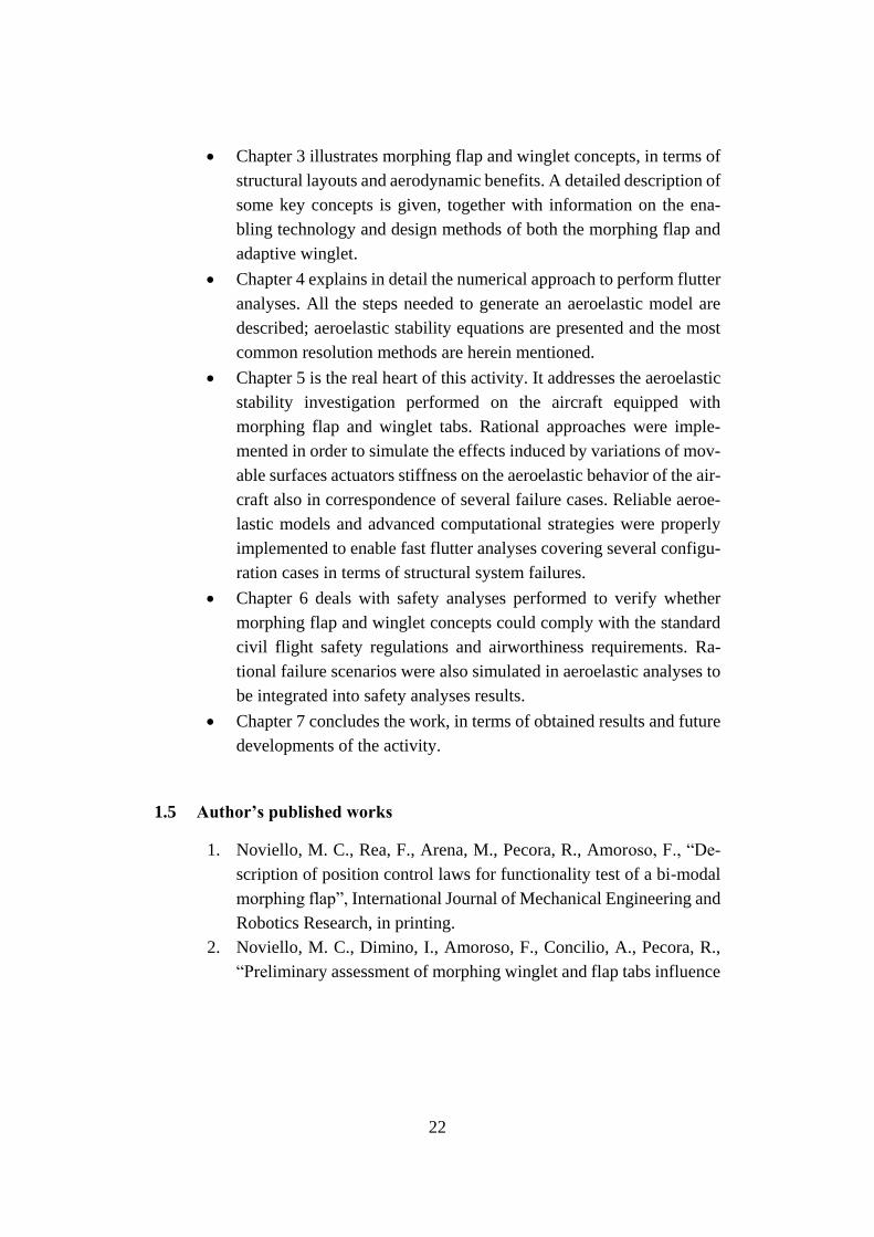
• Chapter 3 illustrates morphing flap and winglet concepts, in terms of
structural layouts and aerodynamic benefits. A detailed description of
some key concepts is given, together with information on the ena-
bling technology and design methods of both the morphing flap and
adaptive winglet.
• Chapter 4 explains in detail the numerical approach to perform flutter
analyses. All the steps needed to generate an aeroelastic model are
described; aeroelastic stability equations are presented and the most
common resolution methods are herein mentioned.
• Chapter 5 is the real heart of this activity. It addresses the aeroelastic
stability investigation performed on the aircraft equipped with
morphing flap and winglet tabs. Rational approaches were imple-
mented in order to simulate the effects induced by variations of mov-
able surfaces actuators stiffness on the aeroelastic behavior of the air-
craft also in correspondence of several failure cases. Reliable aeroe-
lastic models and advanced computational strategies were properly
implemented to enable fast flutter analyses covering several configu-
ration cases in terms of structural system failures.
• Chapter 6 deals with safety analyses performed to verify whether
morphing flap and winglet concepts could comply with the standard
civil flight safety regulations and airworthiness requirements. Ra-
tional failure scenarios were also simulated in aeroelastic analyses to
be integrated into safety analyses results.
• Chapter 7 concludes the work, in terms of obtained results and future
developments of the activity.
1.5 Author’s published works
1. Noviello, M. C., Rea, F., Arena, M., Pecora, R., Amoroso, F., “De-
scription of position control laws for functionality test of a bi-modal
morphing flap”, International Journal of Mechanical Engineering and
Robotics Research, in printing.
2. Noviello, M. C., Dimino, I., Amoroso, F., Concilio, A., Pecora, R.,
“Preliminary assessment of morphing winglet and flap tabs influence
23
on the aeroelastic stability of next generation regional aircraft”, Pro-
ceedings of SMASIS Conference on Smart Materials, Adaptive
Structures and Intelligent Systems, September 2018.
3. Rea, F., Amoroso, F., Pecora, R., Noviello, M.C., Arena, M., “Struc-
tural Design of a Multifunctional Morphing Fowler Flap for a Twin-
Prop Regional Aircraft”, Proceedings of SMASIS Conference on
Smart Materials, Adaptive Structures and Intelligent Systems, Sep-
tember 2018.
4. Arena, M., Noviello, M.C., Rea, F., Amoroso, F., Pecora, R., “Con-
trol strategy of an electrically actuated morphing flap for the next
generation green regional aircraft“, Proceedings of SPIE - The Inter-
national Society for Optical Engineering, April 2018.
5. Pecora, R., Amoroso, F., Noviello, M.C., Dimino, I., Concilio, A.,
“Aeroelastic stability analysis of a large civil aircraft equipped with
morphing winglets and adaptive flap tabs”, Proceedings of SPIE -
The International Society for Optical Engineering, April 2018.
6. Bellucci, M., Noviello, M.C., Amoroso, F., Pecora, R., Dimino, I.,
Concilio, A., Book Chapter “Stress Analysis of a Morphing System”,
Morphing Wing Technologies: Large Commercial Aircraft and Civil
Helicopters”, October 27th, 2017.
7. Rea, F., Pecora, R., Amoroso, F., Arena, M., Noviello, M.C.,
Amendola, G., “Aeroelastic stability analysis of a wind tunnel wing
model equipped with a true scale morphing aileron”, International
Journal of Mechanical Engineering and Robotics Research, Vol.6, N.
6, November 2017.
8. Noviello, M.C., Pecora, R., Amoroso, F., Rea, F., Arena, M., Dimino,
I., “Experimental shape reconstruction of a morphing wing trailing
edge in simulated operative conditions”, Proceeding of ICMAE – In-
ternational Conference of Mechanical and Aerospace Engineering,
249-256, July 2017.
9. Arena, M., Pecora, R., Amoroso, F., Noviello, M.C., Rea, F., Con-
cilio, A., “Aeroelastic analysis of an adaptive trailing edge with a
smart elastic skin”, Proceedings of AIP Conference, July 2017.
10. Pecora, R., Amoroso, F., Arena, M., Noviello, M.C., Rea, F., “Exper-
imental validation of a true-scale morphing flap for large civil aircraft
applications”, Proceedings of SPIE - The International Society for
Optical Engineering, April 2017.
24
11. Noviello, M.C., Rea, F., Arena, M., Pecora, R., Amoroso, F., “Actu-
ation and control of a novel wing flap architecture with bi-modal
camber morphing capabilities”, Proceedings of 2016 7th Interna-
tional Conference on Mechanical and Aerospace Engineering, IC-
MAE, July 2016.
12. Rea, F., Arena, M., Noviello, M.C., Pecora, R., Amoroso, F., “Pre-
liminary failure analysis of an innovative morphing flap tailored for
large civil aircraft applications”, Proceedings of 2016 7th Interna-
tional Conference on Mechanical and Aerospace Engineering, IC-
MAE, July 2016.
13. Arena, M., Noviello, M.C., Rea, F., Amoroso, F., Pecora, R.,
Amendola, G., “Modal stability assessment for a morphing aileron
subjected to actuation system failures: Numerical analysis supported
by test evidence”, Proceedings of 2016 7th International Conference
on Mechanical and Aerospace Engineering, ICMAE, July 2016.
25
2 State of the art on morphing structures
2.1 Adaptive wings
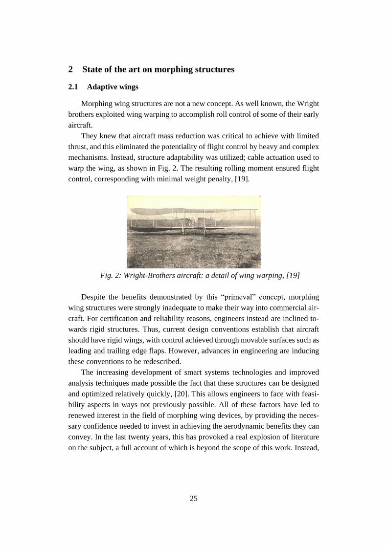
Morphing wing structures are not a new concept. As well known, the Wright
brothers exploited wing warping to accomplish roll control of some of their early
aircraft.
They knew that aircraft mass reduction was critical to achieve with limited
thrust, and this eliminated the potentiality of flight control by heavy and complex
mechanisms. Instead, structure adaptability was utilized; cable actuation used to
warp the wing, as shown in Fig. 2. The resulting rolling moment ensured flight
control, corresponding with minimal weight penalty, [19].
Fig. 2: Wright-Brothers aircraft: a detail of wing warping, [19]
Despite the benefits demonstrated by this “primeval” concept, morphing
wing structures were strongly inadequate to make their way into commercial air-
craft. For certification and reliability reasons, engineers instead are inclined to-
wards rigid structures. Thus, current design conventions establish that aircraft
should have rigid wings, with control achieved through movable surfaces such as
leading and trailing edge flaps. However, advances in engineering are inducing
these conventions to be redescribed.
The increasing development of smart systems technologies and improved
analysis techniques made possible the fact that these structures can be designed
and optimized relatively quickly, [20]. This allows engineers to face with feasi-
bility aspects in ways not previously possible. All of these factors have led to
renewed interest in the field of morphing wing devices, by providing the neces-
sary confidence needed to invest in achieving the aerodynamic benefits they can
convey. In the last twenty years, this has provoked a real explosion of literature
on the subject, a full account of which is beyond the scope of this work. Instead,
26
a summary of key concepts is shown, combined with information on the enabling
technology and design methods.
When dealing with morphing wing structures, the type of morphing is typi-
cally separated into two categories ([21]): morphs which occur in the plane of the
wing itself (planform morphing), varying properties such as wing span, sweep
and planform area; and those normal to it (out-of-plane morphing), where varia-
tions in camber, chord length, and airfoil profile are achieved.
Planform morphing typically results in significantly affected performance,
ensuring the combination of aircraft design requirements previously in discord-
ance each other. For example, high-altitude performance are often at the expense
of low maneuverability and speed to achieve cruise and loiter characteristics.
Similarly, military fighter aircraft achieve maneuverability and high speed, pay-
ing in terms of efficiency, [22]. Thus, planform morphing leads the way toward
a multi-purpose vehicle, capable of operating optimally at both extremes, [23].
Some current concepts, and other novel ideas for large-scale planform morphs,
are demonstrated below.
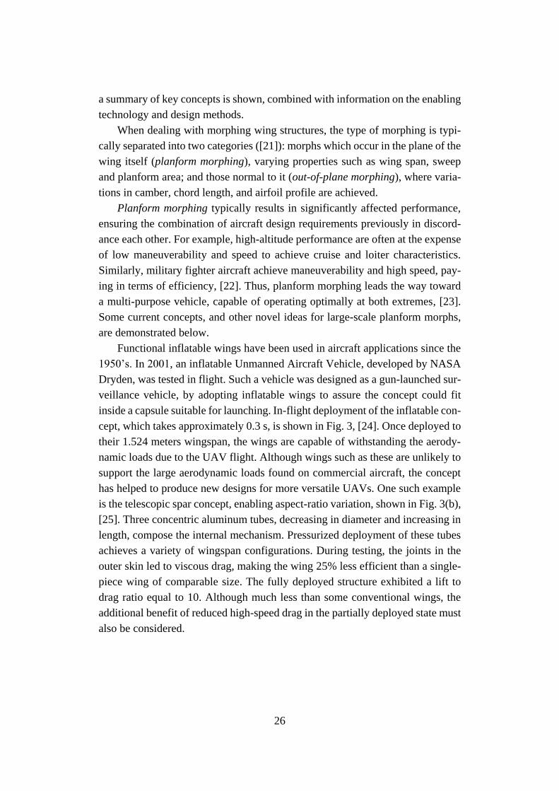
Functional inflatable wings have been used in aircraft applications since the
1950’s. In 2001, an inflatable Unmanned Aircraft Vehicle, developed by NASA
Dryden, was tested in flight. Such a vehicle was designed as a gun-launched sur-
veillance vehicle, by adopting inflatable wings to assure the concept could fit
inside a capsule suitable for launching. In-flight deployment of the inflatable con-
cept, which takes approximately 0.3 s, is shown in Fig. 3, [24]. Once deployed to
their 1.524 meters wingspan, the wings are capable of withstanding the aerody-
namic loads due to the UAV flight. Although wings such as these are unlikely to
support the large aerodynamic loads found on commercial aircraft, the concept
has helped to produce new designs for more versatile UAVs. One such example
is the telescopic spar concept, enabling aspect-ratio variation, shown in Fig. 3(b),
[25]. Three concentric aluminum tubes, decreasing in diameter and increasing in
length, compose the internal mechanism. Pressurized deployment of these tubes
achieves a variety of wingspan configurations. During testing, the joints in the
outer skin led to viscous drag, making the wing 25% less efficient than a single-
piece wing of comparable size. The fully deployed structure exhibited a lift to
drag ratio equal to 10. Although much less than some conventional wings, the
additional benefit of reduced high-speed drag in the partially deployed state must
also be considered.
27
Fig. 3: Morphing wing concept: (a) NASA Dryden inflatable wing during
flight testing [24]; and (b) telescopic wing concept [25]
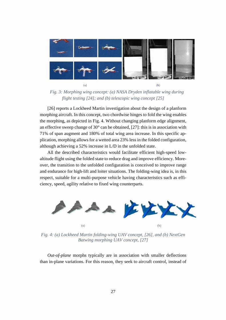
[26] reports a Lockheed Martin investigation about the design of a planform
morphing aircraft. In this concept, two chordwise hinges to fold the wing enables
the morphing, as depicted in Fig. 4. Without changing planform edge alignment,
an effective sweep change of 30° can be obtained, [27]: this is in association with
71% of span augment and 180% of total wing area increase. In this specific ap-
plication, morphing allows for a wetted area 23% less in the folded configuration,
although achieving a 52% increase in L/D in the unfolded state.
All the described characteristics would facilitate efficient high-speed low-
altitude flight using the folded state to reduce drag and improve efficiency. More-
over, the transition to the unfolded configuration is conceived to improve range
and endurance for high-lift and loiter situations. The folding-wing idea is, in this
respect, suitable for a multi-purpose vehicle having characteristics such as effi-
ciency, speed, agility relative to fixed wing counterparts.
Fig. 4: (a) Lockheed Martin folding-wing UAV concept, [26], and (b) NextGen
Batwing morphing UAV concept, [27]
Out-of-plane morphs typically are in association with smaller deflections
than in-plane variations. For this reason, they seek to aircraft control, instead of
28
providing multi-purpose capabilities. Conventional control surfaces and mecha-
nism can be replaced by morphing wing architectures, enabling a smooth and
continuous surface to cleave the flow, retarding the onset separation and the tran-
sition to a turbulent boundary layer. Expedients to reach the aforementioned tar-
gets are several: from camber shape changing, to wing twisting and/or banding
variations.
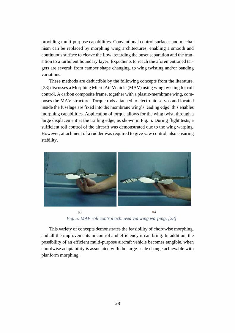
These methods are deductible by the following concepts from the literature.
[28] discusses a Morphing Micro Air Vehicle (MAV) using wing twisting for roll
control. A carbon composite frame, together with a plastic-membrane wing, com-
poses the MAV structure. Torque rods attached to electronic servos and located
inside the fuselage are fixed into the membrane wing’s leading edge: this enables
morphing capabilities. Application of torque allows for the wing twist, through a
large displacement at the trailing edge, as shown in Fig. 5. During flight tests, a
sufficient roll control of the aircraft was demonstrated due to the wing warping.
However, attachment of a rudder was required to give yaw control, also ensuring
stability.
Fig. 5: MAV roll control achieved via wing warping, [28]
This variety of concepts demonstrates the feasibility of chordwise morphing,
and all the improvements in control and efficiency it can bring. In addition, the
possibility of an efficient multi-purpose aircraft vehicle becomes tangible, when
chordwise adaptability is associated with the large-scale change achievable with
planform morphing.
29
2.2 Clean Sky 2 Airgreen 2 Project
Clean Sky2 is one of the largest research program ever launched at European
level. Funded by the EU’s Horizon 2020 programme, it contributes to establish
European aero-industry collaboration, global leadership and competitiveness
[29]. Large efforts are currently spent through the CleanSky2 program to develop
an efficient air transport system identified through a lower environmental impact
combined to unequalled capabilities of ensuring safe and seamless mobility while
complying with very demanding technological requirements.
Within CleanSky 2 scenario, AirGreen 2 project aims to develop and demon-
strate novel concepts and methodologies for the purposes of a new generation
wing realization. Such a wing will be characterized by:
• an innovative structure, resulting from improved life cycle design;
• a high level of adaptability (shape-changing), enabling load control
and alleviation functions, and improving the aerodynamic perfor-
mance at the different flight regimes;
• an innovative aerodynamic design, to preserve of the natural laminar
flow and for the drag reduction.
The validation platform of the integrated technologies is what is currently
presented -at European Level- as the next generation Green Regional Aircraft
(GRA). Active from 2006, GRA panel aims to conceive, validate and demon-
strate “green” aeronautical technologies best fitting the regional aircraft that will
fly from 2020 onwards. For that purpose, specific and challenging domains are
considered:
• Advanced low weight and high performance structures;
• All-electric systems and bleed-less engine architectures;
• Low noise/high efficiency aerodynamic;
• Environmentally optimized missions and trajectories management.
Such technologies are destined to two different aircraft concepts, identified
by means of two seat classes, [29]:
1. 90-seat, with Turboprop engine (TP90);
2. 130-seat, with a combination of novel propulsion solutions, as the
Geared Turbofan (GTF), the Advanced Turbofan (ATF) and the
Open Rotor (OR) configuration.
30
TP90 will be considered as the reference platform for the integration of
morphing flaps and winglets concepts in this thesis.
An overview of the AG2 morphing technologies investigated is provided in
the following section, for the sake of completeness.
2.3 Overview on AG2 morphing devices
The REG IADP objective is to bring the integration of technologies for Re-
gional Aircraft to a further level of complexity with respect to the achievements
of Clean Sky GRA. Retaining GRA outcomes, advanced technologies for re-
gional aircraft are being further developed and will be integrated and validated at
aircraft level, so as to drastically de-risk their integration on future regional air-
craft product, [29].
In the framework of Clean Sky 2 REG-IADP, three morphing wing devices
are developed with the aim of improving aerodynamic performance of Leonardo
TP90 A/C: drooped nose, morphing flap and morphing winglet. Such high TRL
studies include A/C integration, on-ground testing and in-flight validation.
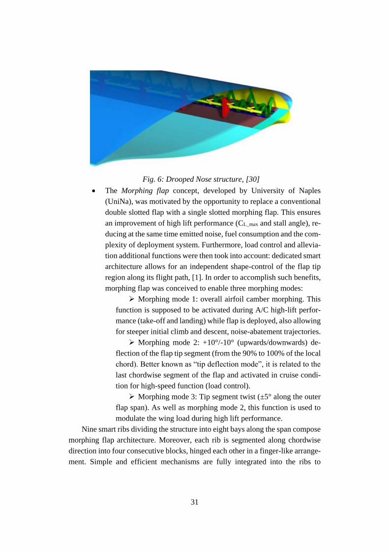
• The Drooped nose identifies the Morphing Leading Edge, which is
one of the most investigated morphing concepts since many years. In
particular, it can be included into the most general active camber-
morphing sector, where the main goal is to modify the airfoil camber
to improve the A/C aerodynamic performance. Moreover, specific
performance requirements have been posed, in terms of CL_max en-
hancement with respect the reference configuration, equal to 2.4%
and 1.7%, considering both trailing and leading edge morphing ef-
fects in take-off and landing, respectively. To achieve these benefits,
the drooped nose structure was conceived in a “bio-inspired” config-
uration based on a higher number of compliant rib. This architectural
strategy, developed by University Of Milan (PoliMi) allows for re-
ducing the thickness of the ribs and the number of stiffeners, only
used as connection between the load paths and the skin. The leading
edge target shape change can be obtained without skin length varia-
tion. In this way, the morphing LE can change its aerodynamic shape
in an efficient way, without generating axial stresses, [30]. A repre-
sentation of the drooped nose is depicted in Fig. 6.
31
Fig. 6: Drooped Nose structure, [30]
• The Morphing flap concept, developed by University of Naples
(UniNa), was motivated by the opportunity to replace a conventional
double slotted flap with a single slotted morphing flap. This ensures
an improvement of high lift performance (CL_max and stall angle), re-
ducing at the same time emitted noise, fuel consumption and the com-
plexity of deployment system. Furthermore, load control and allevia-
tion additional functions were then took into account: dedicated smart
architecture allows for an independent shape-control of the flap tip
region along its flight path, [1]. In order to accomplish such benefits,
morphing flap was conceived to enable three morphing modes:
➢ Morphing mode 1: overall airfoil camber morphing. This
function is supposed to be activated during A/C high-lift perfor-
mance (take-off and landing) while flap is deployed, also allowing
for steeper initial climb and descent, noise-abatement trajectories.
➢ Morphing mode 2: +10°/-10° (upwards/downwards) de-
flection of the flap tip segment (from the 90% to 100% of the local
chord). Better known as “tip deflection mode”, it is related to the
last chordwise segment of the flap and activated in cruise condi-
tion for high-speed function (load control).
➢ Morphing mode 3: Tip segment twist (±5° along the outer
flap span). As well as morphing mode 2, this function is used to
modulate the wing load during high lift performance.
Nine smart ribs dividing the structure into eight bays along the span compose
morphing flap architecture. Moreover, each rib is segmented along chordwise
direction into four consecutive blocks, hinged each other in a finger-like arrange-
ment. Simple and efficient mechanisms are fully integrated into the ribs to
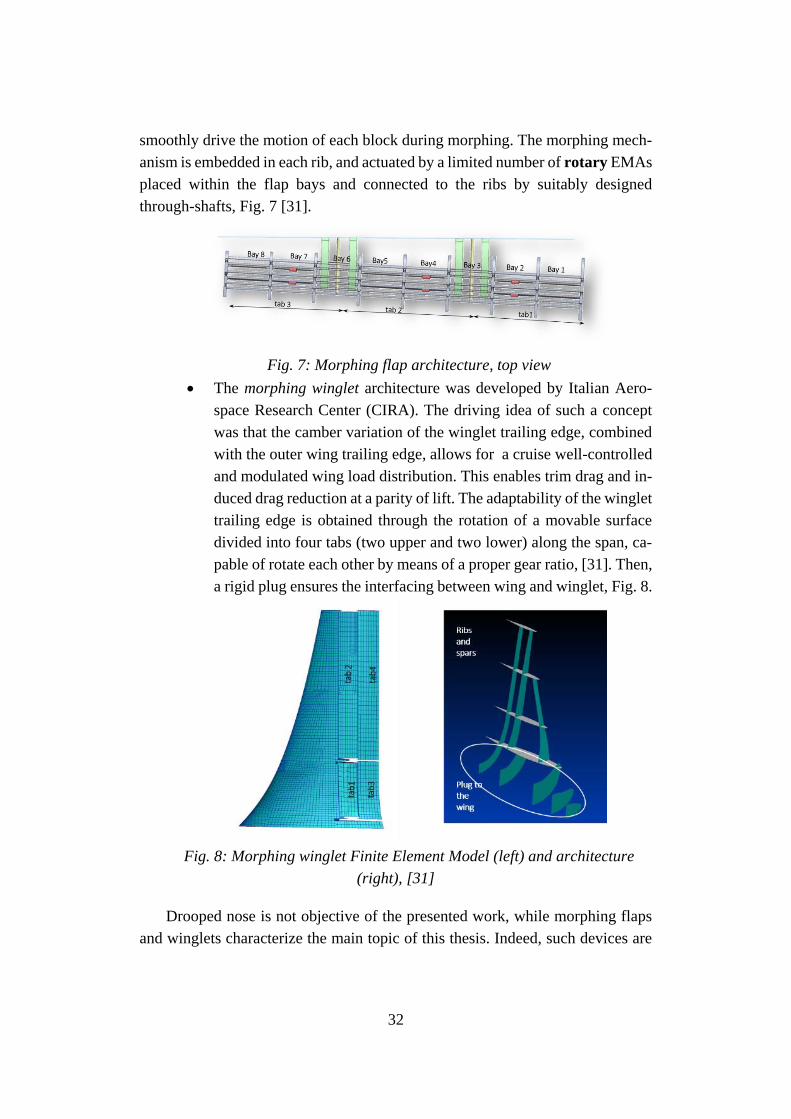
32
smoothly drive the motion of each block during morphing. The morphing mech-
anism is embedded in each rib, and actuated by a limited number of rotary EMAs
placed within the flap bays and connected to the ribs by suitably designed
through-shafts, Fig. 7 [31].
Fig. 7: Morphing flap architecture, top view
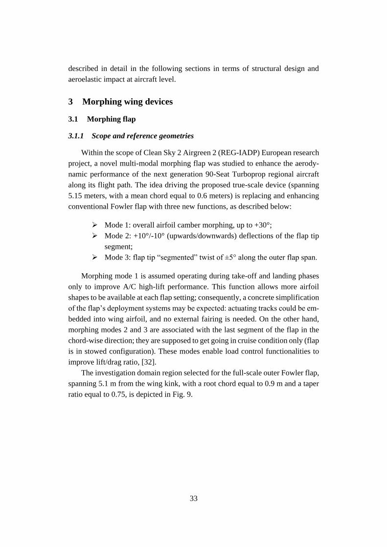
• The morphing winglet architecture was developed by Italian Aero-
space Research Center (CIRA). The driving idea of such a concept
was that the camber variation of the winglet trailing edge, combined
with the outer wing trailing edge, allows for a cruise well-controlled
and modulated wing load distribution. This enables trim drag and in-
duced drag reduction at a parity of lift. The adaptability of the winglet
trailing edge is obtained through the rotation of a movable surface
divided into four tabs (two upper and two lower) along the span, ca-
pable of rotate each other by means of a proper gear ratio, [31]. Then,
a rigid plug ensures the interfacing between wing and winglet, Fig. 8.
Fig. 8: Morphing winglet Finite Element Model (left) and architecture
(right), [31]
Drooped nose is not objective of the presented work, while morphing flaps
and winglets characterize the main topic of this thesis. Indeed, such devices are
33
described in detail in the following sections in terms of structural design and
aeroelastic impact at aircraft level.
3 Morphing wing devices
3.1 Morphing flap
3.1.1 Scope and reference geometries
Within the scope of Clean Sky 2 Airgreen 2 (REG-IADP) European research
project, a novel multi-modal morphing flap was studied to enhance the aerody-
namic performance of the next generation 90-Seat Turboprop regional aircraft
along its flight path. The idea driving the proposed true-scale device (spanning
5.15 meters, with a mean chord equal to 0.6 meters) is replacing and enhancing
conventional Fowler flap with three new functions, as described below:
➢ Mode 1: overall airfoil camber morphing, up to +30°;
➢ Mode 2: +10°/-10° (upwards/downwards) deflections of the flap tip
segment;
➢ Mode 3: flap tip “segmented” twist of ±5° along the outer flap span.
Morphing mode 1 is assumed operating during take-off and landing phases
only to improve A/C high-lift performance. This function allows more airfoil
shapes to be available at each flap setting; consequently, a concrete simplification
of the flap’s deployment systems may be expected: actuating tracks could be em-
bedded into wing airfoil, and no external fairing is needed. On the other hand,
morphing modes 2 and 3 are associated with the last segment of the flap in the
chord-wise direction; they are supposed to get going in cruise condition only (flap
is in stowed configuration). These modes enable load control functionalities to
improve lift/drag ratio, [32].
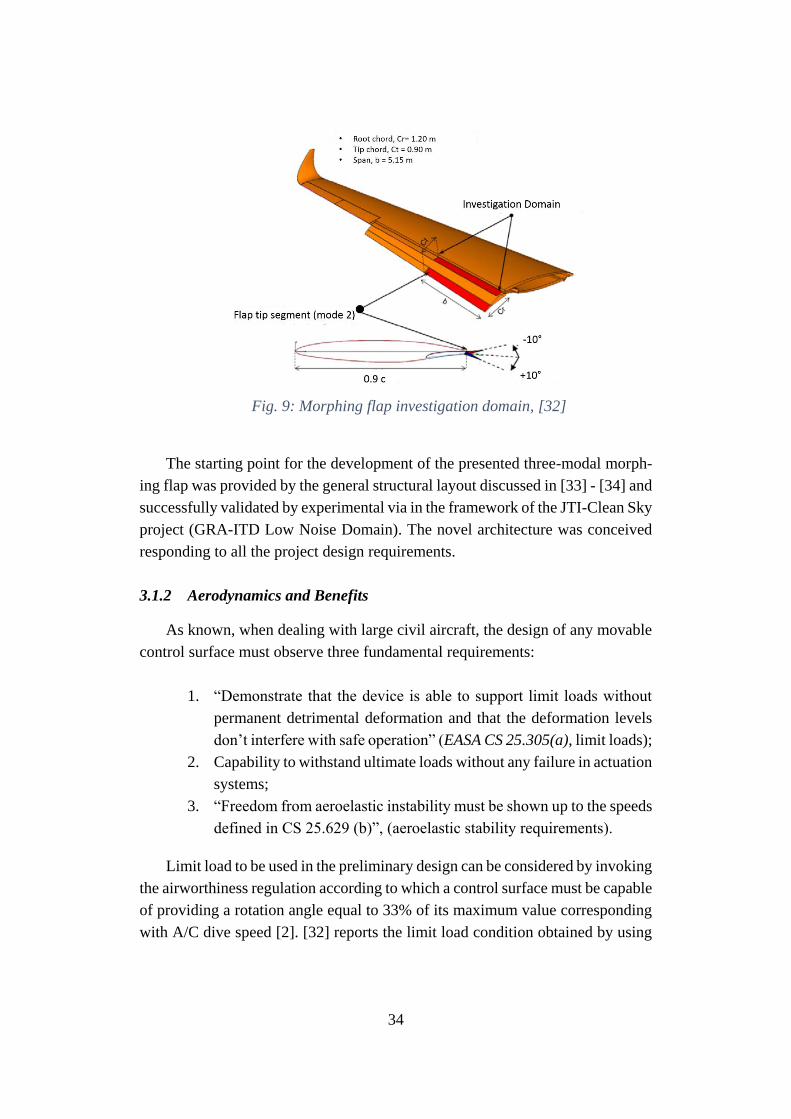
The investigation domain region selected for the full-scale outer Fowler flap,
spanning 5.1 m from the wing kink, with a root chord equal to 0.9 m and a taper
ratio equal to 0.75, is depicted in Fig. 9.
34
Fig. 9: Morphing flap investigation domain, [32]
The starting point for the development of the presented three-modal morph-
ing flap was provided by the general structural layout discussed in [33] - [34] and
successfully validated by experimental via in the framework of the JTI-Clean Sky
project (GRA-ITD Low Noise Domain). The novel architecture was conceived
responding to all the project design requirements.
3.1.2 Aerodynamics and Benefits
As known, when dealing with large civil aircraft, the design of any movable
control surface must observe three fundamental requirements:
1. “Demonstrate that the device is able to support limit loads without
permanent detrimental deformation and that the deformation levels
don’t interfere with safe operation” (EASA CS 25.305(a), limit loads);
2. Capability to withstand ultimate loads without any failure in actuation
systems;
3. “Freedom from aeroelastic instability must be shown up to the speeds
defined in CS 25.629 (b)”, (aeroelastic stability requirements).
Limit load to be used in the preliminary design can be considered by invoking
the airworthiness regulation according to which a control surface must be capable
of providing a rotation angle equal to 33% of its maximum value corresponding
with A/C dive speed [2]. [32] reports the limit load condition obtained by using
35
an in-house 2D Doublet Lattice Method (DLM) code, herein showed in Table 1
for the sake of completeness.
Tab rotation (down) +5 deg
Tab mean geometric chord 0.236 m
Pressure coefficient (upper), 0.3247
Pressure coefficient (lower), 0.5011
Dynamic pressure, 12005 Pa
Dynamic Pressure (upper), 𝑞 ∗
𝐶𝑝,𝑈𝑃
3898 Pa
Dynamic Pressure (lower), 𝑞 ∗
𝐶𝑝,𝐿𝑂𝑊
6015 Pa
Force resultant (upper), 𝐹𝑈𝑃 2378 N
Force resultant (lower), 𝐹𝐿𝑂𝑊 3668 N
Hinge moment around tab hinge axis,
𝑀B3
475.8 N*m
Table 1: Aerodynamic values in limit load condition, [32]
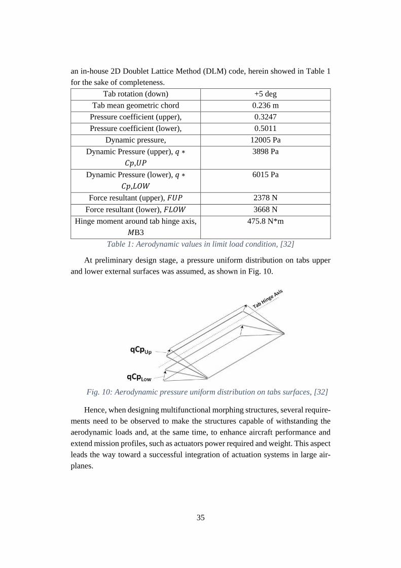
At preliminary design stage, a pressure uniform distribution on tabs upper
and lower external surfaces was assumed, as shown in Fig. 10.
Fig. 10: Aerodynamic pressure uniform distribution on tabs surfaces, [32]
Hence, when designing multifunctional morphing structures, several require-
ments need to be observed to make the structures capable of withstanding the
aerodynamic loads and, at the same time, to enhance aircraft performance and
extend mission profiles, such as actuators power required and weight. This aspect
leads the way toward a successful integration of actuation systems in large air-
planes.
36
3.1.3 Morphing flap architecture
The successful technology demonstration of a bi-modal morphing flap
(2MMF) in JTI-Clean Sky (GRA-ITD) project scenario drove the design of the
herein presented three-modal morphing flap (3MMF), objective of the Clean Sky
2 REGIADP AG2 project. Several design improvements have been achieved, if
comparing 3MMF with 2MMF, [32].
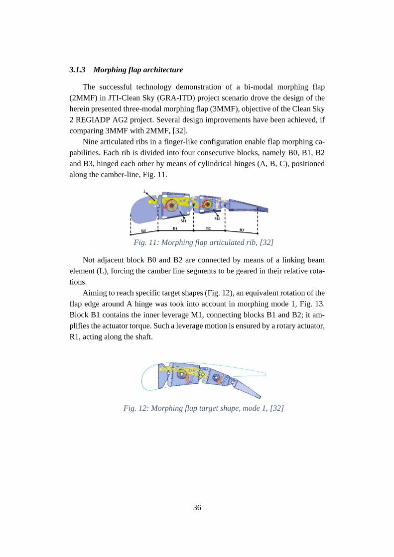
Nine articulated ribs in a finger-like configuration enable flap morphing ca-
pabilities. Each rib is divided into four consecutive blocks, namely B0, B1, B2
and B3, hinged each other by means of cylindrical hinges (A, B, C), positioned
along the camber-line, Fig. 11.
Fig. 11: Morphing flap articulated rib, [32]
Not adjacent block B0 and B2 are connected by means of a linking beam
element (L), forcing the camber line segments to be geared in their relative rota-
tions.
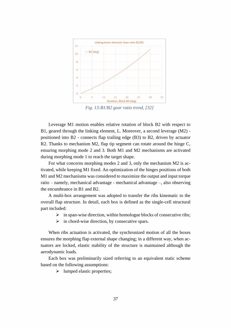
Aiming to reach specific target shapes (Fig. 12), an equivalent rotation of the
flap edge around A hinge was took into account in morphing mode 1, Fig. 13.
Block B1 contains the inner leverage M1, connecting blocks B1 and B2; it am-
plifies the actuator torque. Such a leverage motion is ensured by a rotary actuator,
R1, acting along the shaft.
Fig. 12: Morphing flap target shape, mode 1, [32]
37
Fig. 13:B1/B2 gear ratio trend, [32]
Leverage M1 motion enables relative rotation of block B2 with respect to
B1, geared through the linking element, L. Moreover, a second leverage (M2) -
positioned into B2 - connects flap trailing edge (B3) to B2, driven by actuator
R2. Thanks to mechanism M2, flap tip segment can rotate around the hinge C,
ensuring morphing mode 2 and 3. Both M1 and M2 mechanisms are activated
during morphing mode 1 to reach the target shape.
For what concerns morphing modes 2 and 3, only the mechanism M2 is ac-
tivated, while keeping M1 fixed. An optimization of the hinges positions of both
M1 and M2 mechanisms was considered to maximize the output and input torque
ratio – namely, mechanical advantage - mechanical advantage –, also observing
the encumbrance in B1 and B2.
A multi-box arrangement was adopted to transfer the ribs kinematic to the
overall flap structure. In detail, each box is defined as the single-cell structural
part included:
➢ in span-wise direction, within homologue blocks of consecutive ribs;
➢ in chord-wise direction, by consecutive spars.
When ribs actuation is activated, the synchronized motion of all the boxes
ensures the morphing flap external shape changing; in a different way, when ac-
tuators are locked, elastic stability of the structure is maintained although the
aerodynamic loads.
Each box was preliminarily sized referring to an equivalent static scheme
based on the following assumptions:
➢ lumped elastic properties;
38
➢ Spars, rib plates and skin panels made of AL2024-T5 alloy;
➢ Ultimate load obtained multiplying limit loads by 1.5 (safety factor);
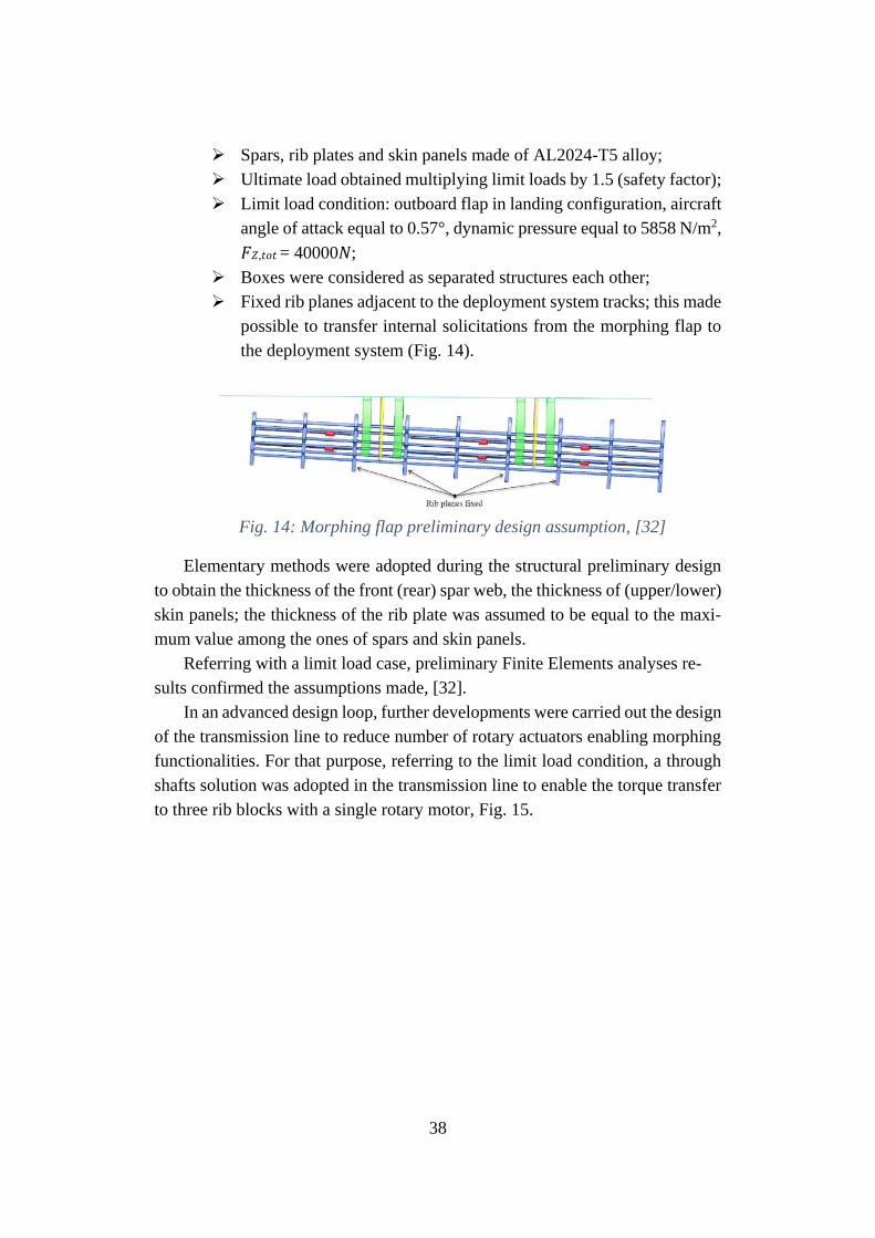
➢ Limit load condition: outboard flap in landing configuration, aircraft
angle of attack equal to 0.57°, dynamic pressure equal to 5858 N/m2,
𝐹𝑍,𝑡𝑜𝑡 = 40000𝑁;
➢ Boxes were considered as separated structures each other;
➢ Fixed rib planes adjacent to the deployment system tracks; this made
possible to transfer internal solicitations from the morphing flap to
the deployment system (Fig. 14).
Fig. 14: Morphing flap preliminary design assumption, [32]
Elementary methods were adopted during the structural preliminary design
to obtain the thickness of the front (rear) spar web, the thickness of (upper/lower)
skin panels; the thickness of the rib plate was assumed to be equal to the maxi-
mum value among the ones of spars and skin panels.
Referring with a limit load case, preliminary Finite Elements analyses re-
sults confirmed the assumptions made, [32].
In an advanced design loop, further developments were carried out the design
of the transmission line to reduce number of rotary actuators enabling morphing
functionalities. For that purpose, referring to the limit load condition, a through
shafts solution was adopted in the transmission line to enable the torque transfer
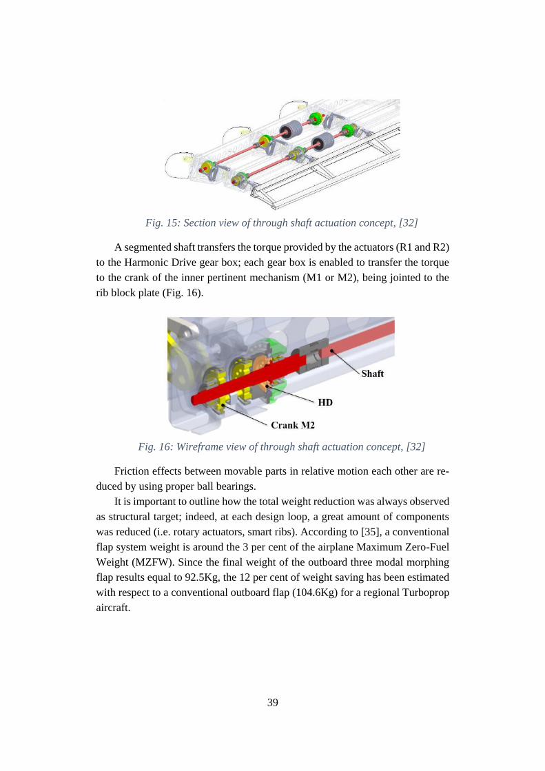
to three rib blocks with a single rotary motor, Fig. 15.
39
Fig. 15: Section view of through shaft actuation concept, [32]
A segmented shaft transfers the torque provided by the actuators (R1 and R2)
to the Harmonic Drive gear box; each gear box is enabled to transfer the torque
to the crank of the inner pertinent mechanism (M1 or M2), being jointed to the
rib block plate (Fig. 16).
Fig. 16: Wireframe view of through shaft actuation concept, [32]
Friction effects between movable parts in relative motion each other are re-
duced by using proper ball bearings.
It is important to outline how the total weight reduction was always observed
as structural target; indeed, at each design loop, a great amount of components
was reduced (i.e. rotary actuators, smart ribs). According to [35], a conventional
flap system weight is around the 3 per cent of the airplane Maximum Zero-Fuel
Weight (MZFW). Since the final weight of the outboard three modal morphing
flap results equal to 92.5Kg, the 12 per cent of weight saving has been estimated
with respect to a conventional outboard flap (104.6Kg) for a regional Turboprop
aircraft.
40
3.2 Morphing winglet
3.2.1 Scope and reference geometries
Research on morphing aircraft structures aims to wing design optimization
by considering co-factors involving both aerodynamics and structures. Morphing
devices applications can bring to several benefits in terms of aircraft perfor-
mance, as literature studies teach. Among such applications, shape-changing
winglets can enhance Lift-on-Drag ratio in off-design conditions and reduce aer-
odynamic wing loads by providing adapted geometry and wing lift distribution
throughout the A/C flight envelope. This can potentially lead the way toward
adaptive winglets application to the next generation aircraft. For that purpose, the
structural design of a multi-modal morphing winglet is collocated within the
scope of Clean Sky 2 Regional Aircraft IADP (see section 2), made in compli-
ance with the pertinent requirements posed by the airworthiness regulations.
The morphing winglet concept observes the following assumptions:
• Morphing winglet system chord equal to the 40% of the mean winglet
chord;
• Deflection range = [-15°, +10°] (negative deflections when reducing root
bending moment).
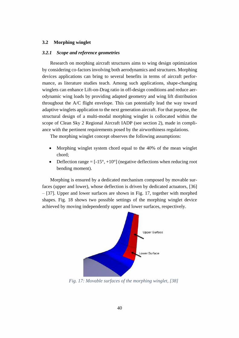
Morphing is ensured by a dedicated mechanism composed by movable sur-
faces (upper and lower), whose deflection is driven by dedicated actuators, [36]
– [37]. Upper and lower surfaces are shown in Fig. 17, together with morphed
shapes. Fig. 18 shows two possible settings of the morphing winglet device
achieved by moving independently upper and lower surfaces, respectively.
Fig. 17: Movable surfaces of the morphing winglet, [38]
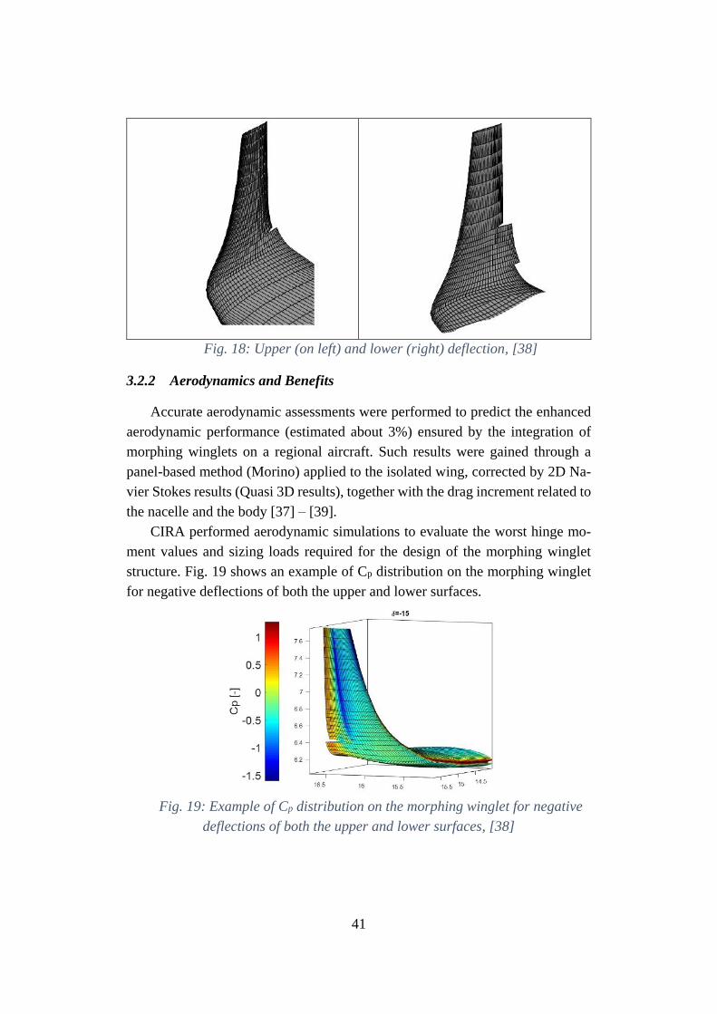
41
Fig. 18: Upper (on left) and lower (right) deflection, [38]
3.2.2 Aerodynamics and Benefits
Accurate aerodynamic assessments were performed to predict the enhanced
aerodynamic performance (estimated about 3%) ensured by the integration of
morphing winglets on a regional aircraft. Such results were gained through a
panel-based method (Morino) applied to the isolated wing, corrected by 2D Na-
vier Stokes results (Quasi 3D results), together with the drag increment related to
the nacelle and the body [37] – [39].
CIRA performed aerodynamic simulations to evaluate the worst hinge mo-
ment values and sizing loads required for the design of the morphing winglet
structure. Fig. 19 shows an example of Cp distribution on the morphing winglet
for negative deflections of both the upper and lower surfaces.
Fig. 19: Example of Cp distribution on the morphing winglet for negative
deflections of both the upper and lower surfaces, [38]
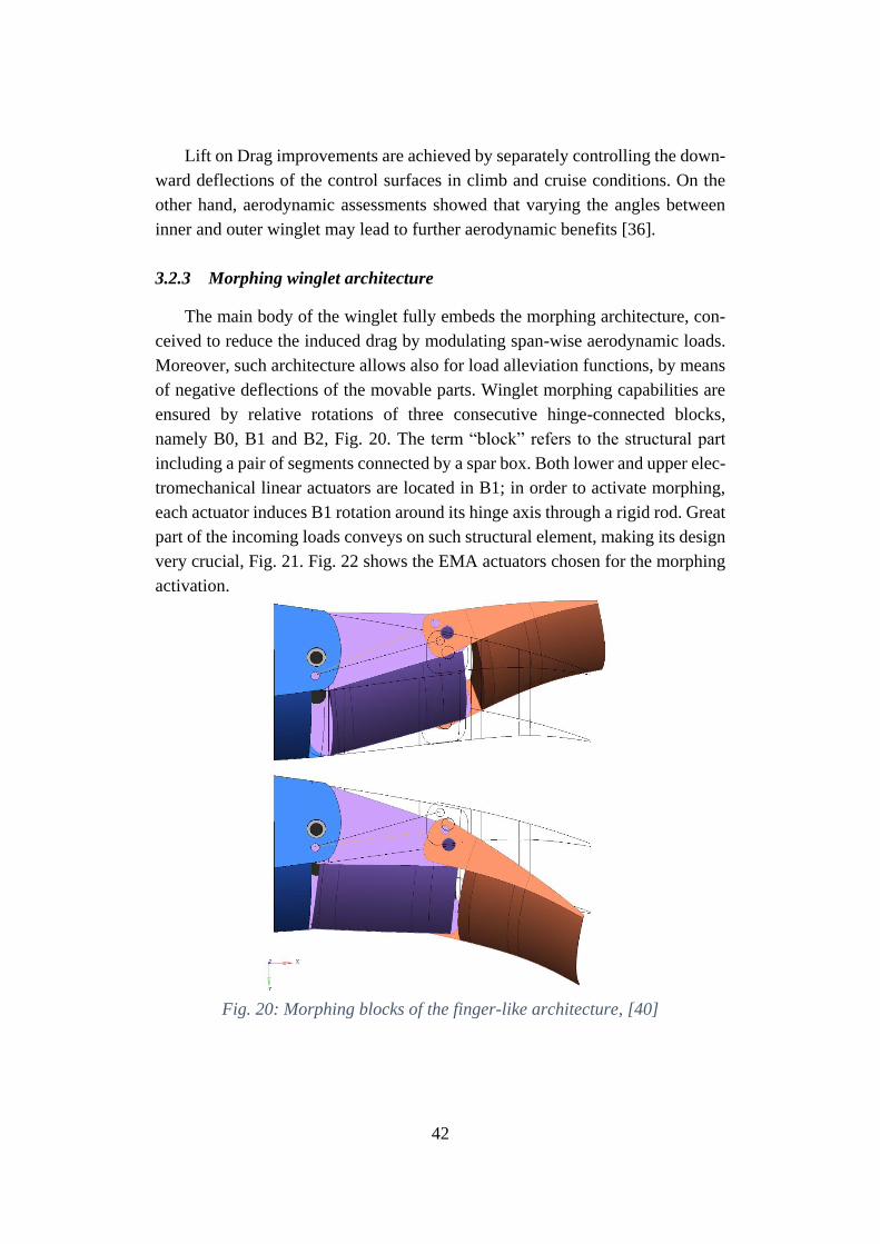
42
Lift on Drag improvements are achieved by separately controlling the down-
ward deflections of the control surfaces in climb and cruise conditions. On the
other hand, aerodynamic assessments showed that varying the angles between
inner and outer winglet may lead to further aerodynamic benefits [36].
3.2.3 Morphing winglet architecture
The main body of the winglet fully embeds the morphing architecture, con-
ceived to reduce the induced drag by modulating span-wise aerodynamic loads.
Moreover, such architecture allows also for load alleviation functions, by means
of negative deflections of the movable parts. Winglet morphing capabilities are
ensured by relative rotations of three consecutive hinge-connected blocks,
namely B0, B1 and B2, Fig. 20. The term “block” refers to the structural part
including a pair of segments connected by a spar box. Both lower and upper elec-
tromechanical linear actuators are located in B1; in order to activate morphing,
each actuator induces B1 rotation around its hinge axis through a rigid rod. Great
part of the incoming loads conveys on such structural element, making its design
very crucial, Fig. 21. Fig. 22 shows the EMA actuators chosen for the morphing
activation.
Fig. 20: Morphing blocks of the finger-like architecture, [40]
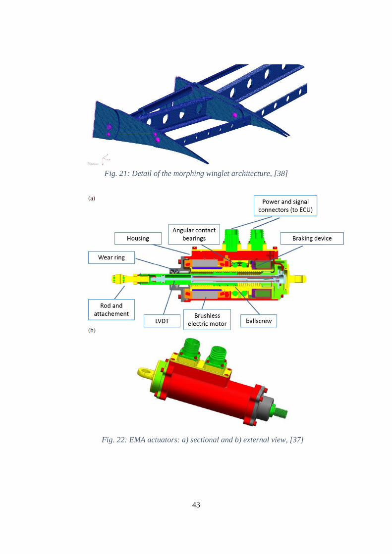
43
Fig. 21: Detail of the morphing winglet architecture, [38]
Fig. 22: EMA actuators: a) sectional and b) external view, [37]
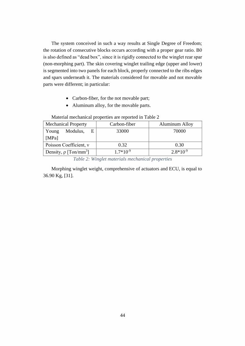
44
The system conceived in such a way results at Single Degree of Freedom;
the rotation of consecutive blocks occurs according with a proper gear ratio. B0
is also defined as “dead box”, since it is rigidly connected to the winglet rear spar
(non-morphing part). The skin covering winglet trailing edge (upper and lower)
is segmented into two panels for each block, properly connected to the ribs edges
and spars underneath it. The materials considered for movable and not movable
parts were different; in particular:
• Carbon-fiber, for the not movable part;
• Aluminum alloy, for the movable parts.
Material mechanical properties are reported in Table 2
Mechanical Property Carbon-fiber Aluminum Alloy
Young Modulus, E
[MPa]
33000 70000
Poisson Coefficient, ν 0.32 0.30
Density, ρ [Ton/mm3] 1.7*10-9 2.8*10-9
Table 2: Winglet materials mechanical properties
Morphing winglet weight, comprehensive of actuators and ECU, is equal to
36.90 Kg, [31].
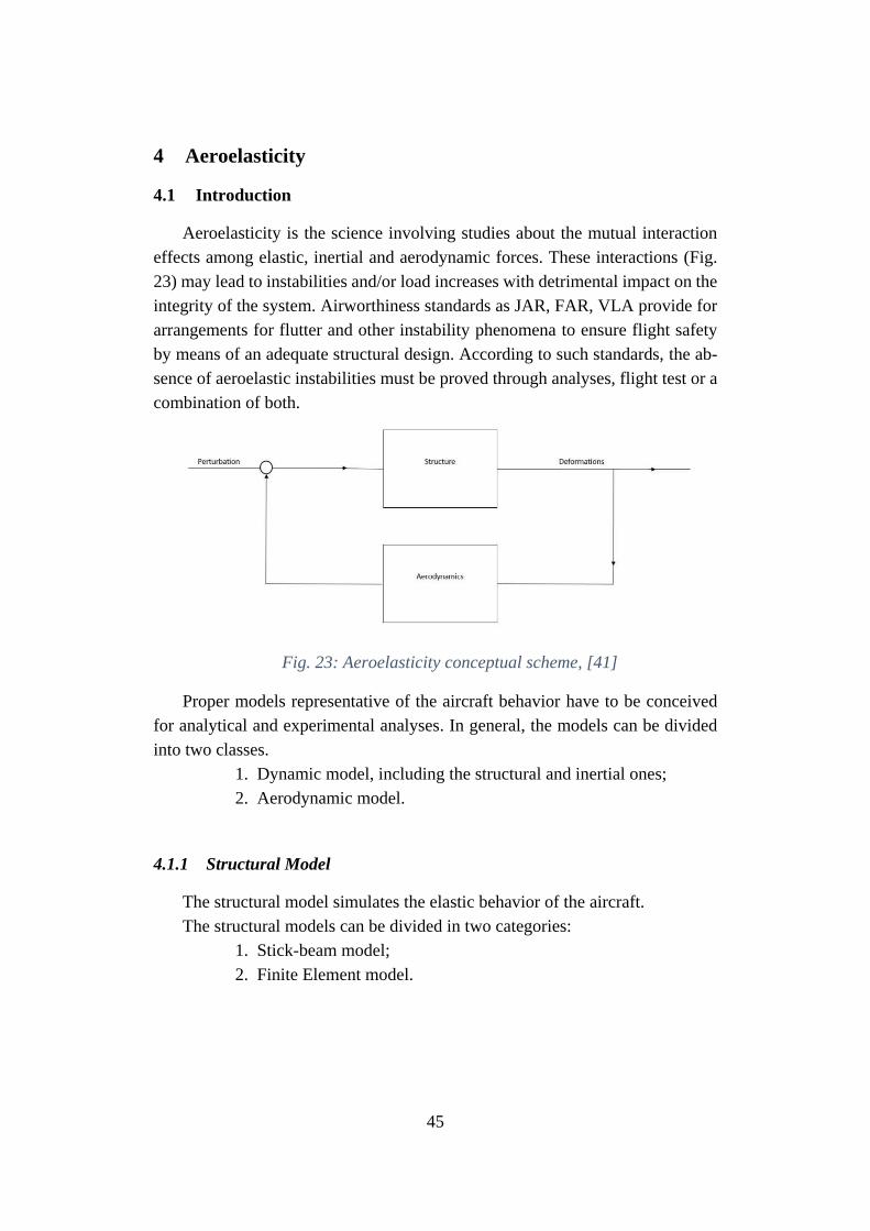
45
4 Aeroelasticity
4.1 Introduction
Aeroelasticity is the science involving studies about the mutual interaction
effects among elastic, inertial and aerodynamic forces. These interactions (Fig.
23) may lead to instabilities and/or load increases with detrimental impact on the
integrity of the system. Airworthiness standards as JAR, FAR, VLA provide for
arrangements for flutter and other instability phenomena to ensure flight safety
by means of an adequate structural design. According to such standards, the ab-
sence of aeroelastic instabilities must be proved through analyses, flight test or a
combination of both.
Fig. 23: Aeroelasticity conceptual scheme, [41]
Proper models representative of the aircraft behavior have to be conceived
for analytical and experimental analyses. In general, the models can be divided
into two classes.
1. Dynamic model, including the structural and inertial ones;
2. Aerodynamic model.
4.1.1 Structural Model
The structural model simulates the elastic behavior of the aircraft.
The structural models can be divided in two categories:
1. Stick-beam model;
2. Finite Element model.
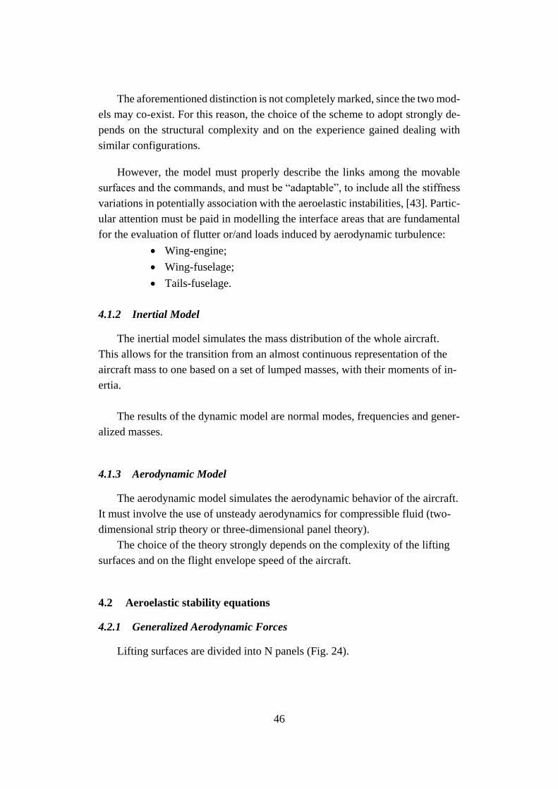
46
The aforementioned distinction is not completely marked, since the two mod-
els may co-exist. For this reason, the choice of the scheme to adopt strongly de-
pends on the structural complexity and on the experience gained dealing with
similar configurations.
However, the model must properly describe the links among the movable
surfaces and the commands, and must be “adaptable”, to include all the stiffness
variations in potentially association with the aeroelastic instabilities, [43]. Partic-
ular attention must be paid in modelling the interface areas that are fundamental
for the evaluation of flutter or/and loads induced by aerodynamic turbulence:
• Wing-engine;
• Wing-fuselage;
• Tails-fuselage.
4.1.2 Inertial Model
The inertial model simulates the mass distribution of the whole aircraft.
This allows for the transition from an almost continuous representation of the
aircraft mass to one based on a set of lumped masses, with their moments of in-
ertia.
The results of the dynamic model are normal modes, frequencies and gener-
alized masses.
4.1.3 Aerodynamic Model
The aerodynamic model simulates the aerodynamic behavior of the aircraft.
It must involve the use of unsteady aerodynamics for compressible fluid (two-
dimensional strip theory or three-dimensional panel theory).
The choice of the theory strongly depends on the complexity of the lifting
surfaces and on the flight envelope speed of the aircraft.
4.2 Aeroelastic stability equations
4.2.1 Generalized Aerodynamic Forces
Lifting surfaces are divided into N panels (Fig. 24).
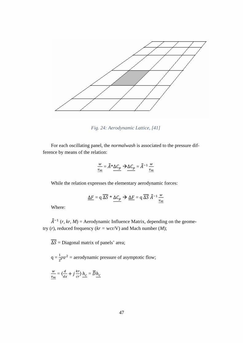
47
Fig. 24: Aerodynamic Lattice, [41]
For each oscillating panel, the normalwash is associated to the pressure dif-
ference by means of the relation:
𝑤
𝑣∞ = ��*∆𝐶𝑝 ∆𝐶𝑝 = ��−1 𝑤
𝑣∞
While the relation expresses the elementary aerodynamic forces:
∆𝐹 = q ∆𝑆 * ∆𝐶𝑝 ∆𝐹 = q ∆𝑆 ��−1 𝑤
𝑣∞
Where:
��−1 (r, kr, M) = Aerodynamic Influence Matrix, depending on the geome-
try (r), reduced frequency (kr = wcr/V) and Mach number (M);
∆𝑆 = Diagonal matrix of panels’ area;
q = 1
2ρ𝑣2 = aerodynamic pressure of asymptotic flow;
𝑤
𝑣∞ = ⟨
𝑑
𝑑𝑥+ 𝑗
𝑘𝑟
𝑐𝑟⟩ ℎ𝑐 = ��ℎ𝑐
48
�� = substantial derivative matrix;
x = asymptotic flow direction;
ℎ𝑐 = normal displacements vector in correspondence with control points.
The virtual work of the aerodynamic forces is given by:
δL =δh𝑖𝑡 ∆𝐹 q δh𝑖
𝑡 ∆𝑆 ��−1��ℎ𝑐 (1)
where:
ℎ𝑖 = normal displacements vector in correspondence with integration
points.
Both hi and hc are related to the structural displacements Zst through interpo-
lation matrix depending exclusively on the geometry.
ℎ𝑐 = 𝐺 𝐴𝐾 𝐶 (𝑟) 𝑍𝑠𝑡ℎ𝑖 = 𝐺 𝐴𝐾
𝑖 (𝑟) 𝑍𝑠𝑡 (2)
By integrating the Eq. 2 into Eq. 1, the latter becomes:
δL(𝑍𝑠𝑡) = q δ𝑍𝑠𝑡𝑇𝐺 𝐴𝐾
𝑖 (𝑟) 𝑇∆𝑆 ��−1𝐷𝐺 𝐴𝐾 𝐶 (𝑟) 𝑍𝑠𝑡 (3)
By projecting the structural displacements in the normal mode space, 𝑍𝑠𝑡 =
𝛷(𝑟) 𝜂(𝑡), where:
𝛷(𝑟) = normal modes matrix;
𝜂(𝑡) = lagrangian coordinates vector,
The virtual work of aerodynamic forces expressed as a function of η is:
δL(𝜂) = q δ𝜂𝑇 𝑄(𝑘𝑟,𝑀) 𝜂,
With 𝑄(𝑘𝑟,𝑀) = 𝛷𝑇 𝐺𝐴𝐾𝐼 (𝑟)𝑇 ∆𝑆 ��−1𝐷𝐺 𝐴𝐾
𝐶 (𝑟) ��.
4.2.2 Impedance matrix
Kinetic energy (T), elastic energy (U) and dissipation function (D) have the
following expressions, [41]:
49
T = (1/2)��𝑇 �� ��
U = (1/2)𝑍𝑇 �� 𝑍
D = (1/2)��𝑇 �� ��
And by introducing the modal coordinates:
T = (1/2) ��𝑇 𝑀𝑔 ��
U = (1/2) 𝜂𝑇 𝐾𝑔 𝜂
D = (1/2) ��𝑇 𝜎𝑔 ��
Where:
𝑀𝑔 = generalized diagonal mass matrix
𝐾𝑔 = generalized diagonal stiffness matrix
𝜎𝑔 = modal damping matrix (diagonal under the Basile Hypothesis).
Given the Lagrange relation:
𝑑
𝑑𝑡 𝜕𝑇
𝜕��+
𝜕𝐷
𝜕��+
𝜕𝑈
𝜕𝜂 =
𝜕𝐿
𝜕𝜂
Its Fourier transform in presence of the external forces, 𝐹 𝑔 𝑒𝑥𝑡 (𝑗𝜔) =
𝛷𝑇 𝐹 𝑒𝑥𝑡 (𝑗𝜔), totally independent form the movement of the structure leads to
the aeroelastic equilibrium equation:
�� (𝑗𝜔; 𝑉∞)𝜂(𝑗𝜔) = 𝐹 𝑔 𝑒𝑥𝑡 (𝑗𝜔)
Where:
�� (𝑗𝜔; 𝑉∞) = [(𝑗𝜔)2��𝑔 + (𝑗𝜔) 𝜎𝑔 + (𝐾𝑔 −
1
2ρ𝑉∞
2𝑄(𝑘𝑟,𝑀) )] (4)
Is the impedance matrix, the inverse of which is the transfer matrix.
Both of them are dependent from the flight speed.
50
The time-domain solutions of the generalized coordinates are obtained by
the inverse Fourier transform of the (4 ),as expressed in the (5):
𝜂(𝑡) =1
2𝜋 ∫ ��−1+∞
−∞(𝑗𝜔; 𝑉∞)𝐹 𝑔 𝑒𝑥𝑡 (𝑗𝜔)exp (𝑗𝜔𝑡)𝑑𝜔 (5)
The asymptotic stability1 of the system under an imposed unit impulse forc-
ing is ensured by the condition:
∫ |𝐻−1 +∞
−∞
(𝑗𝜔; 𝑉∞)| 𝑑𝜔 ≤ 0
The transfer matrix at a fixed speed is expressed as a polynomial ratio:
��−1(𝑗𝜔; 𝑉∞) = ∑ ��𝑖
𝑛𝑖=0 (𝑗𝜔)𝑖
∑ 𝑏𝑖𝑛𝑖=0 (𝑗𝜔)𝑖
,
Where the numerator is a polynomial of real matrixes of order n, while the
denominator is a scalar polynomial with real coefficients of order m, equal to the
number of the generalized coordinates multiplied by 2. Due to the system causal-
ity, n at maximum can reach the value m. In order to guarantee the dynamic sta-
bility of the system, the denominator cannot have any root with negative real part.
In other words, the poles of the rational representation of the transfer matrix must
be included into the negative quadrant of the complex plane. The denominator is
the determinant of the impedance matrix �� (𝑗𝜔; 𝑉∞).
A numerical and very efficient method to calculate the determinant of a ma-
trix is based on the calculus of its eigenvectors.
Flutter speed is defined as the speed value corresponding to a pole with real
part equal to zero at least.
4.3 Classification of the methods for flutter evaluation
The aeroelastic stability equation in absence of the constant term has the
following expression ([41] – [43]):
−𝜔2��𝜂 + 𝑗𝜔𝜎𝐺 𝜂 + ��𝜂 = (1
2)ρ𝑣2 �� (𝑘𝑟)𝜂 (6)
1 |𝜂(𝑡)| ≤ 0, 𝑖𝑓 𝑡 → ∞
51
With kr is the reduced frequency, equal to ω𝑐𝑟/v (𝑐𝑟 is the reference
length).
The methods to calculate the roots of the (6) as functions of the speed can
be divided into three classes:
a) K methods;
b) PK methods;
c) Methods of state equations.
4.3.1 K methods
4.3.1.1 K method, First version
By using the definition of reduced frequency discussed in §4.3 and by sub-
stituting the following expression:
𝑣2 = (𝜔𝑐𝑟
𝑘𝑟)2
The Eq. 6 becomes:
[𝑗𝜔𝜎𝐺 + �� ]𝜂 = 𝜔2 [𝜌𝑐𝑟2
2∗
𝑄 (𝑘𝑟)
𝑘𝑟2+ 𝑀]𝜂
And considering the hysteretic damping 𝜎𝐺 = 𝑔
𝜔��:
(1 + 𝑗𝑔)��𝜂 = 𝜔2 [𝜌𝑐𝑟2
2∗
𝑄 (𝑘𝑟)
𝑘𝑟2+ 𝑀]𝜂
From which:
𝜆𝜂 = ��𝜂,
where:
𝜆 = 𝜆𝑅 + 𝑗𝜆𝐼 = 1+𝑗𝑔
𝜔2
�� = 𝐾−1 [𝜌𝑐𝑟2
2∗
��(𝑘𝑟)
𝑘𝑟2+ ��
The roots are found by means of the solution of the eigenvalues of a com-
plex matrix, according to what described as follows:
1. Reduced frequency fixed, Kri;
2. �� (Kri;) matrix evaluation;
3. �� matrix construction:
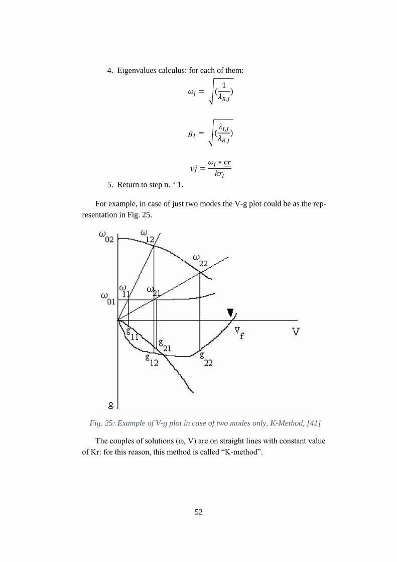
52
4. Eigenvalues calculus: for each of them:
𝜔𝑗 = √(1
𝜆𝑅,𝐽)
𝑔𝑗 = √(𝜆𝐼,𝐽
𝜆𝑅,𝐽)
𝑣𝑗 =𝜔𝑗 ∗ 𝑐𝑟
𝑘𝑟𝐼
5. Return to step n. ° 1.
For example, in case of just two modes the V-g plot could be as the rep-
resentation in Fig. 25.
Fig. 25: Example of V-g plot in case of two modes only, K-Method, [41]
The couples of solutions (ω, V) are on straight lines with constant value
of Kr: for this reason, this method is called “K-method”.
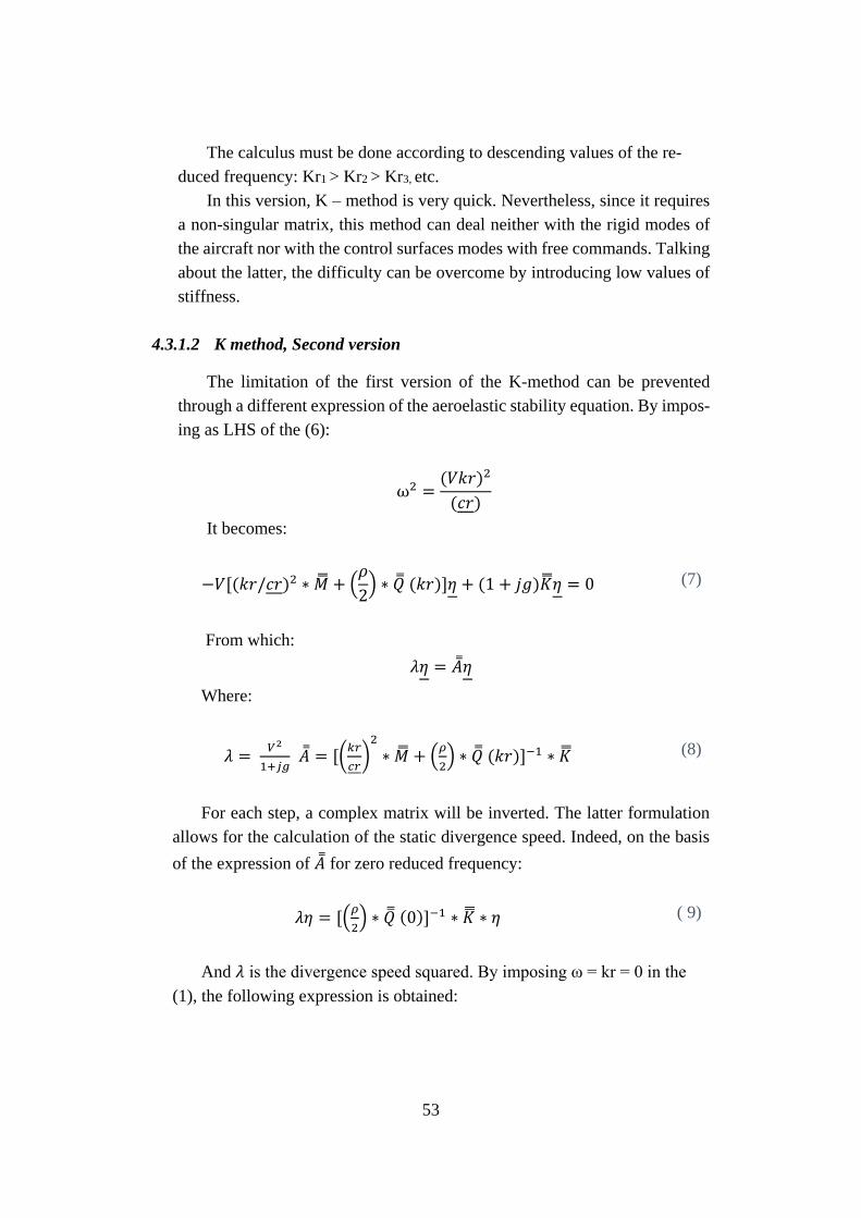
53
The calculus must be done according to descending values of the re-
duced frequency: Kr1 > Kr2 > Kr3, etc.
In this version, K – method is very quick. Nevertheless, since it requires
a non-singular matrix, this method can deal neither with the rigid modes of
the aircraft nor with the control surfaces modes with free commands. Talking
about the latter, the difficulty can be overcome by introducing low values of
stiffness.
4.3.1.2 K method, Second version
The limitation of the first version of the K-method can be prevented
through a different expression of the aeroelastic stability equation. By impos-
ing as LHS of the (6):
ω2 =(𝑉𝑘𝑟)2
(𝑐𝑟)
It becomes:
−𝑉[(𝑘𝑟/𝑐𝑟)2 ∗ �� + (𝜌
2) ∗ �� (𝑘𝑟)]𝜂 + (1 + 𝑗𝑔)��𝜂 = 0 (7)
From which:
𝜆𝜂 = ��𝜂
Where:
𝜆 = 𝑉2
1+𝑗𝑔 �� = [(
𝑘𝑟
𝑐𝑟)2
∗ �� + (𝜌
2) ∗ �� (𝑘𝑟)]−1 ∗ �� (8)
For each step, a complex matrix will be inverted. The latter formulation
allows for the calculation of the static divergence speed. Indeed, on the basis
of the expression of �� for zero reduced frequency:
𝜆𝜂 = [(𝜌
2) ∗ �� (0)]−1 ∗ �� ∗ 𝜂 ( 9)
And 𝜆 is the divergence speed squared. By imposing ω = kr = 0 in the
(1), the following expression is obtained:
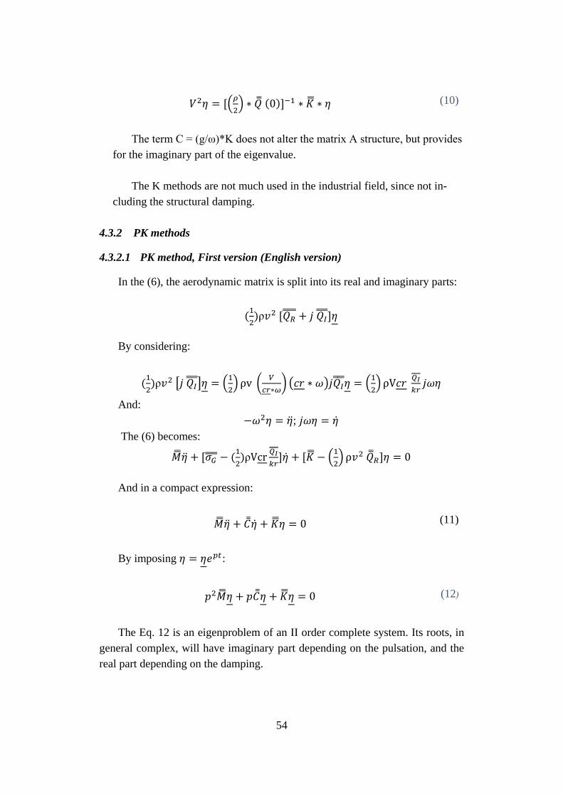
54
𝑉2𝜂 = [(𝜌
2) ∗ �� (0)]−1 ∗ �� ∗ 𝜂 (10)
The term C = (g/ω)*K does not alter the matrix A structure, but provides
for the imaginary part of the eigenvalue.
The K methods are not much used in the industrial field, since not in-
cluding the structural damping.
4.3.2 PK methods
4.3.2.1 PK method, First version (English version)
In the (6), the aerodynamic matrix is split into its real and imaginary parts:
(1
2)ρ𝑣2 [𝑄𝑅
+ 𝑗 𝑄𝐼 ]𝜂
By considering:
(1
2)ρ𝑣2 [𝑗 𝑄𝐼
]𝜂 = (1
2) ρv (
𝑉
𝑐𝑟∗𝜔) (𝑐𝑟 ∗ 𝜔)𝑗𝑄𝐼
𝜂 = (1
2) ρV𝑐𝑟
𝑄𝐼
𝑘𝑟𝑗𝜔𝜂
And:
−𝜔2𝜂 = ��; 𝑗𝜔𝜂 = ��
The (6) becomes:
���� + [𝜎𝐺 − (1
2)ρVcr
𝑄𝐼
𝑘𝑟]�� + [�� − (
1
2) ρ𝑣2 ��𝑅]𝜂 = 0
And in a compact expression:
���� + ���� + ��𝜂 = 0 (11)
By imposing 𝜂 = 𝜂𝑒𝑝𝑡:
𝑝2��𝜂 + 𝑝��𝜂 + ��𝜂 = 0 (12)
The Eq. 12 is an eigenproblem of an II order complete system. Its roots, in
general complex, will have imaginary part depending on the pulsation, and the
real part depending on the damping.
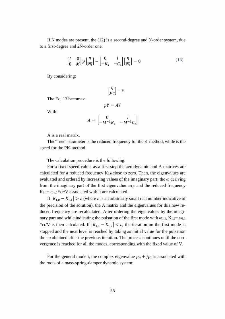
55
If N modes are present, the (12) is a second-degree and N-order system, due
to a first-degree and 2N-order one:
[𝐼 00 𝑀
] 𝑝 [𝜂𝑝𝜂] − [
0 𝐼−𝐾𝑠 −𝐶𝑠
] [𝜂𝑝𝜂] = 0 (13)
By considering:
[𝜂𝑝𝜂] = Y
The Eq. 13 becomes:
𝑝𝑌 = 𝐴𝑌
With:
𝐴 = [0 𝐼
−𝑀−1𝐾𝑠 −𝑀−1𝐶𝑠]
A is a real matrix.
The “free” parameter is the reduced frequency for the K-method, while is the
speed for the PK-method.
The calculation procedure is the following:
For a fixed speed value, as a first step the aerodynamic and A matrices are
calculated for a reduced frequency K1,0 close to zero. Then, the eigenvalues are
evaluated and ordered by increasing values of the imaginary part; the ω deriving
from the imaginary part of the first eigenvalue ω1,0 and the reduced frequency
K1,1= ω1,0 *cr/V associated with it are calculated.
If |𝐾1,0 − 𝐾1,1| > 𝜀 (where 𝜀 is an arbitrarily small real number indicative of
the precision of the solution), the A matrix and the eigenvalues for this new re-
duced frequency are recalculated. After ordering the eigenvalues by the imagi-
nary part and while indicating the pulsation of the first mode with ω1,1, K1,2= ω1,1
*cr/V is then calculated. If |𝐾1,1 − 𝐾1,2| < 𝜀, the iteration on the first mode is
stopped and the next level is reached by taking as initial value for the pulsation
the ω2 obtained after the previous iteration. The process continues until the con-
vergence is reached for all the modes, corresponding with the fixed value of V.
For the general mode i, the complex eigenvalue 𝑝𝑅 + 𝑗𝑝𝑖 is associated with
the roots of a mass-spring-damper dynamic system:
56
𝑝 = −𝜁𝜔 + 𝑗𝜔√(1 − 𝜁2) , 𝑝𝑅 = −𝜁𝜔, 𝑝𝑖 = 𝜔√(1 − 𝜁2)
From the ratio -𝑝𝑖
𝑝𝑅=
√(1−𝜁2)
𝜁 the quantity 𝜁𝜔 can be evaluated and
then 𝜔 = − 𝑝𝑅
𝜁.
Compared to the K method, the PK-method is more costly from a computa-
tional point of view. Anyway, it allows for taking into account the structural
damping and, in this version (called English version), the solutions can be ob-
tained regardless of the previous solutions.
4.3.2.2 PK method, Second Version (Continuation method)
The aeroelastic stability equation:
[𝑝2𝑀 + 𝑝𝜎 + 𝐾 −1
2𝜌𝑉2𝑄(𝑘𝑟)] 𝜂 = 0 (14)
can be considered as a vectorial equation as a function of p, η:
𝐹(𝑝, 𝜂) = 0 (15)
By adding to the (15) a normalization condition for η:
𝜂𝑡 ∗ 𝑊 ∗ 𝜂 = 1
And by imposing:
𝐺(𝜂) = 𝜂𝑡 ∗ 𝑊 ∗ 𝜂 − 1 = 0 (16)
The Eq. 15 and 16 can be seen as non linear equations system as functions
of p and η:
𝐹(𝑝, 𝜂) = 0
𝐺(𝜂) = 0
(17)
57
By expanding the (17) about a fixed speed value point, 𝑝0, 𝜂0:
𝐹(𝑝, 𝜂) = 𝐹(𝑝0, 𝜂0) +𝜕𝐹
𝜕𝑝∗ ∆𝑝 +
𝜕𝐹
𝜕𝜂∗ ∆𝜂
𝐺(𝜂) = 𝐺(𝜂0) +𝜕𝐺𝑅
𝜕𝜂∗ ∆𝜂
(18)
Where:
𝐹𝑝 = 𝜕𝐹
𝜕𝑝= [2𝑝 𝑀 + 𝜎 −
1
2 𝜌 𝑣2 𝜕𝑄(𝑘𝑟)
𝜕𝑘𝑟
𝜕𝑘𝑟
𝜕𝑝]*η
𝐹𝜂 = 𝜕𝐹
𝜕𝜂= [𝑝2 𝑀 + 𝑝𝜎 + 𝐾 −
1
2 𝜌 𝑣2 𝑄(𝑘𝑟)
𝐺𝜂𝑅 =
𝜕𝐺𝑅
𝜕𝜂= 2 𝜂𝑇 ∗ 𝑊
𝐺𝜂𝑅 row vector.
By using the (17), the (18) becomes:
−𝐹(𝑝0, 𝜂0) = 𝐹𝑝 ∗ ∆𝑝 + 𝐹𝜂 ∗ ∆𝜂
−𝐺(𝜂0) = 𝐺𝜂𝑅 ∗ ∆𝜂
(19)
And by imposing:
𝑉1 = 𝐹𝜂−1 ∗ 𝐹(𝑝0, 𝜂0); 𝑉2 = 𝐹𝜂
−1 ∗ 𝐹𝑝
From the first of the (19):
∆𝜂 = −𝑉1 − 𝑉2 ∗ ∆𝑝 (20)
58
And by replacing in the second of the (19):
∆𝑝 =𝐺𝜂
𝑟∗𝑉1−𝐺(𝜂0)
𝐺𝜂𝑟∗𝑉1
(21)
Known ∆p, from the (20) ∆η can be obtained and then:
𝑝1 = 𝑝0 + ∆𝑝; 𝜂1 = 𝜂0 + ∆𝜂
If |∆p|<ε, the convergence for the i-mode is reached and the procedure goes
on for a new speed value. At first, for the i-mode calculation for a speed close
to zero the assumptions are the following:
𝑝𝑜𝑟 = − 𝜁𝑖𝜔𝑛𝑖
𝑝𝑜𝑖 = 𝜔𝑛𝑖√(1 − 𝜁𝑖2)
𝜔𝑛𝑖 = 𝑛𝑎𝑡𝑢𝑟𝑎𝑙 𝑝𝑢𝑙𝑠𝑎𝑡𝑖𝑜𝑛
𝜁𝑖 = 𝑚𝑜𝑑𝑎𝑙 𝑑𝑎𝑚𝑝𝑖𝑛𝑔 𝑐𝑜𝑒𝑓𝑓𝑖𝑐𝑖𝑒𝑛𝑡
𝜂0 = 𝑛𝑢𝑙𝑙 𝑣𝑒𝑐𝑡𝑜𝑟, 𝑤𝑖𝑡ℎ 𝑡ℎ𝑒 𝑜𝑛𝑙𝑦 𝑖 𝑢𝑛𝑖𝑡𝑎𝑟𝑦 𝑐𝑜𝑚𝑝𝑜𝑛𝑒𝑛𝑡
For the second speed, the previous iteration values are taken, while for the
next speeds all the p values are linearly extrapolated between the two immedi-
ately previous iterations. For η the value of the last iteration is assumed.
The computational speed of the PK-method is comparable to the K-method
one.
4.4 Aerodynamic forces approximation
At each step of the solution methods, the aerodynamic matrix Q must be cal-
culated, [41].
In general, Q matrices evaluation occurs for a limited range of reduced fre-
quencies and, if required, they need to be interpolated.
The interpolation techniques are basically two:
59
a) Linear splines;
b) Rational approximations.
Roger [42] provides an excellent rational approximation:
𝑄(𝑘𝑟) = 𝐴0 + (𝑗𝑘𝑟)𝐴1 + (𝑗𝑘𝑟)2𝐴2 + ∑𝐵𝐿
4
𝐿=1
∗(𝑗𝑘𝑟)
(𝑗𝑘𝑟) + 𝛾𝐿 (22)
The values of 𝛾𝐿 depend on the reduced frequencies values for which Q ma-
trices are known.
To speed up the convergence of the method, A0 = Q(0). The unknown real
matrices: A1 A2 B1 B2 B3 B4 are evaluated by means of the least square method
about the difference Q(kr) - Q(0). It is simple to obtain the Q matrix correspond-
ing with a proper reduced frequency value, if the coefficients matrices are known.
The derived matrix Q(kr)kr can be also achieved through the expansion, and this
is useful in the II PK method.
4.4.1 P method
By exploiting the Rogers approximation and by imposing:
𝑞0 =1
2𝜌𝑉2 ; 𝑞1 =
1
2𝜌𝑉𝑐𝑟; 𝑞2 =
1
2𝜌𝑐𝑟2
The following expression can be obtained:
𝑞0𝑄(𝑘𝑟)𝜂 = [𝑞0𝐴0 + 𝑞1𝐴1(𝑗𝜔) + 𝑞2𝐴2(𝑗𝜔)2] ∗ 𝜂 + 𝑞0 ∑ 𝐵𝐿4𝐿=1 ∗
(𝑗𝜔)∗𝜂
(𝑗𝜔)+𝛾𝐿∗𝑣
𝑐𝑟
(23)
By substituting it into the aeroelastic stability equation:
(𝑗𝜔)2[𝑀 − 𝑞2𝐴2]𝜂 + (𝑗𝜔)[𝜎 − 𝑞1𝐴1]𝜂 + [𝐾 − 𝑞0𝐴0 ]𝜂 −
𝑞0 ∑ 𝐵𝐿4𝐿=1 ∗
(𝑗𝜔)∗𝜂
(𝑗𝜔)+𝛾𝐿∗𝑣
𝑐𝑟
= 0 (24)
60
Then, setting:
𝑀𝑠 = [𝑀 − 𝑞2𝐴2]; 𝐶𝑠 = [𝜎 − 𝑞1𝐴1]; 𝐾𝑠 = [𝐾 − 𝑞0𝐴0]; 𝛾𝐿 = 𝐵𝐿 ∗(𝑗𝜔)∗𝜂
(𝑗𝜔)+𝛾𝐿∗𝑣
𝑐𝑟
; L=1.4
(24) becomes:
(𝑗𝜔)2𝑀𝑠𝜂 + (𝑗𝜔)𝐶𝑠𝜂 + 𝐾𝑠𝜂 − 𝑞0 ∑ 𝑌𝑙4𝑙=1 = 0 (25)
𝛾𝐿 ∗ [(𝑗𝜔) + 𝛾𝐿 ∗𝑣
𝑐𝑟] = 𝐵𝐿 ∗ (𝑗𝜔) ∗ 𝜂; L=1.4
Then assuming:
(𝑗𝜔)2𝜂 = ��; (𝑗𝜔)𝜂 = ��; (𝑗𝜔)𝑌𝐿 = 𝑌��
(25) can be written as follows:
𝑀𝑠�� + 𝐶𝑠�� + 𝐾𝑠η − 𝑞0 ∑ 𝑌𝑙4𝑙=1 = 0 (26)
��𝑙 + (𝛾𝐿𝑣
𝑐𝑟) 𝑌𝐿 − 𝐵𝐿�� = 0; L=1.4
Adding the identity:
�� − �� = 0
It is possible to express constant coefficients differential equations system:
�� = 𝐴𝑍 (27)
Where:
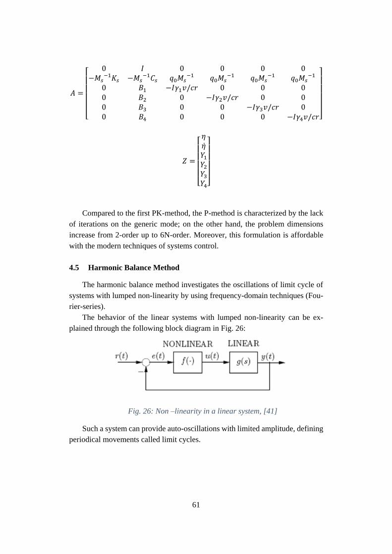
61
𝐴 =
[
0 𝐼 0 0 0 0−𝑀𝑠
−1𝐾𝑠 −𝑀𝑠−1𝐶𝑠 𝑞0𝑀𝑠
−1 𝑞0𝑀𝑠−1 𝑞0𝑀𝑠
−1 𝑞0𝑀𝑠−1
0 𝐵1 −𝐼𝛾1𝑣/𝑐𝑟 0 0 00 𝐵2 0 −𝐼𝛾2𝑣/𝑐𝑟 0 00 𝐵3 0 0 −𝐼𝛾3𝑣/𝑐𝑟 00 𝐵4 0 0 0 −𝐼𝛾4𝑣/𝑐𝑟]
𝑍 =
[ 𝜂��𝑌1
𝑌2
𝑌3
𝑌4]
Compared to the first PK-method, the P-method is characterized by the lack
of iterations on the generic mode; on the other hand, the problem dimensions
increase from 2-order up to 6N-order. Moreover, this formulation is affordable
with the modern techniques of systems control.
4.5 Harmonic Balance Method
The harmonic balance method investigates the oscillations of limit cycle of
systems with lumped non-linearity by using frequency-domain techniques (Fou-
rier-series).
The behavior of the linear systems with lumped non-linearity can be ex-
plained through the following block diagram in Fig. 26:
Fig. 26: Non –linearity in a linear system, [41]
Such a system can provide auto-oscillations with limited amplitude, defining
periodical movements called limit cycles.
62
If the system is enabled to filter the high-frequency harmonics, as a first at-
tempt, the amplitude and the frequency of the only first harmonic can characterize
the whole limit cycle. This hypothesis is valid in flutter conditions.
If the system is described by the following equation:
�� + 𝑓(𝑥, ��) = 0 (28)
Setting:
𝑥 = 𝐴𝑠𝑖𝑛(𝜔𝑡) (29)
From which:
�� = 𝜔𝐴𝑐𝑜𝑠(𝜔𝑡) (30)
The function will be:
𝑓(𝑥, ��) = 𝑓(𝐴𝑠𝑖𝑛(𝜔𝑡), 𝜔𝐴𝑐𝑜𝑠(𝜔𝑡))
Approximating the function 𝑓(𝑥, ��) by its first Fourier harmonic:
𝑓(𝑥, ��) = 𝑎0 + 𝑎1 cos(𝜔𝑡) + 𝑏1sin (𝜔𝑡)
Where:
𝑎0 =1
𝑇∫ 𝑓(𝑡)𝑑𝑡
𝑇
0
𝑎1 =2
𝑇∫ 𝑓(𝑡) cos (𝜔𝑡)𝑑𝑡
𝑇
0
𝑎2 =2
𝑇∫ 𝑓(𝑡) sin (𝜔𝑡)𝑑𝑡
𝑇
0
From the (29) and (30) the following expressions can be obtained:
63
sin(𝜔𝑡) =𝑥
𝐴
cos(𝜔𝑡) =��
𝜔𝐴
Inserting them into (28), it becomes:
�� + (𝑎1
𝐴𝜔) �� + (
𝑏1
𝐴) 𝑥 = 0 (31)
(31) is the representation of the linearized equation of the system: the non-
linearity is contained into the (hysteretic) damping term 𝑎1
𝐴𝜔 and in the stiffness
term (𝑏1
𝐴). Both of them depend on the oscillation amplitude, in case of reso-
nance.
If the non-linear function is odd, the damping term is zero, being:
𝑎1 =2
𝑇∫ 𝑓(𝑡) cos (𝜔𝑡)𝑑𝑡
𝑇
0
= 0
The Eq. 31 can also be expressed as:
�� + 𝐾𝑒𝑞𝑥 = 0 (32)
Where the multiplying coefficient Keq is the equivalent stiffness. According
with the Optimal Linearization Blaquiere Method, Keq must minimize the mean
square deviation between the non-linear function f and its approximation Keqx.
The error is equal to:
𝜀(𝐾𝑒𝑞, t) = f(x, ��) − 𝐾𝑒𝑞𝑥 (33)
While the mean square deviation is:
𝐸(𝐾𝑒𝑞, 𝑡) = 𝜀2 = 𝑓2(𝑥, ��) − 2𝐾𝑒𝑞𝑥𝑓(𝑥, ��) + 𝐾𝑒𝑞2 𝑥2 (34)
64
The mean square deviation minimization in the period T is given by the fol-
lowing expression:
1
𝑇∫
𝜕𝐸(𝐾𝑒𝑞,𝑡)
𝜕𝐾𝑒𝑞
𝑇
0𝑑𝑡 = 0 (35)
Where:
𝜕𝐸(𝐾𝑒𝑞, 𝑡)
𝜕𝐾𝑒𝑞= −2𝑥𝑓(𝑥, ��) + 2𝐾𝑒𝑞𝑥
2 (36)
Substituting (36) in (35), the latter becomes:
−2
𝑇∫ 𝑥𝑓(𝑥, ��
𝑇
0)𝑑𝑡 +
2
𝑇𝐾𝑒𝑞 ∫ 𝑥2𝑇
0𝑑𝑡 = 0 (37)
(37) provides the expression of the equivalent stiffness, Keq:
𝐾𝑒𝑞 =∫ 𝑥𝑓(𝑥,��) 𝑑𝑡
𝑇0
∫ 𝑥2 𝑑𝑡𝑇0
(38)
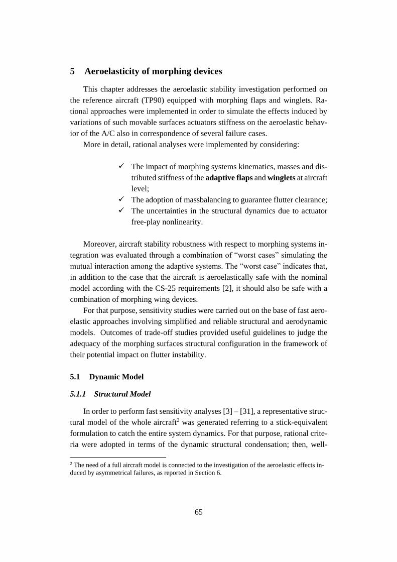
65
5 Aeroelasticity of morphing devices
This chapter addresses the aeroelastic stability investigation performed on
the reference aircraft (TP90) equipped with morphing flaps and winglets. Ra-
tional approaches were implemented in order to simulate the effects induced by
variations of such movable surfaces actuators stiffness on the aeroelastic behav-
ior of the A/C also in correspondence of several failure cases.
More in detail, rational analyses were implemented by considering:
✓ The impact of morphing systems kinematics, masses and dis-
tributed stiffness of the adaptive flaps and winglets at aircraft
level;
✓ The adoption of massbalancing to guarantee flutter clearance;
✓ The uncertainties in the structural dynamics due to actuator
free-play nonlinearity.
Moreover, aircraft stability robustness with respect to morphing systems in-
tegration was evaluated through a combination of “worst cases” simulating the
mutual interaction among the adaptive systems. The “worst case” indicates that,
in addition to the case that the aircraft is aeroelastically safe with the nominal
model according with the CS-25 requirements [2], it should also be safe with a
combination of morphing wing devices.
For that purpose, sensitivity studies were carried out on the base of fast aero-
elastic approaches involving simplified and reliable structural and aerodynamic
models. Outcomes of trade-off studies provided useful guidelines to judge the
adequacy of the morphing surfaces structural configuration in the framework of
their potential impact on flutter instability.
5.1 Dynamic Model
5.1.1 Structural Model
In order to perform fast sensitivity analyses [3] – [31], a representative struc-
tural model of the whole aircraft2 was generated referring to a stick-equivalent
formulation to catch the entire system dynamics. For that purpose, rational crite-
ria were adopted in terms of the dynamic structural condensation; then, well-
2 The need of a full aircraft model is connected to the investigation of the aeroelastic effects in-
duced by asymmetrical failures, as reported in Section 6.
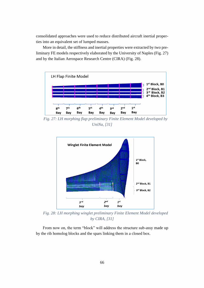
66
consolidated approaches were used to reduce distributed aircraft inertial proper-
ties into an equivalent set of lumped masses.
More in detail, the stiffness and inertial properties were extracted by two pre-
liminary FE models respectively elaborated by the University of Naples (Fig. 27)
and by the Italian Aerospace Research Centre (CIRA) (Fig. 28).
Fig. 27: LH morphing flap preliminary Finite Element Model developed by
UniNa, [31]
Fig. 28: LH morphing winglet preliminary Finite Element Model developed
by CIRA, [31]
From now on, the term “block” will address the structure sub-assy made up
by the rib homolog blocks and the spars linking them in a closed box.
67
All the properties were condensed in a discrete number of structural grids,
which position was driven by the intersection among each hinge/elastic axis and
morphing rib, [31].
More in detail, the elastic axis evaluation of the wing and of the first block
of both morphing flap and winglet was carried out by means of an iterative pro-
cedure, described as follows:
1. A trial position of the elastic axis was assumed;
2. Nodes were added to the structural model in correspondence of the intersec-
tion points between the elastic axis (point 1) and ribs’ planes;
3. At each rib, available RBE2 elements had to slave the nodes of the rib bound-
ary to the node at the intersection between the rib plane and the (imposed)
elastic axis;
4. An arbitrary torque MT, was applied along the elastic axis and in correspond-
ence of its intersection with the plane of the rib located at wing tip. The mas-
ter node on the rib plane at the wing root was constrained in all the degrees
of freedom;
5. Static analysis was performed in MSC-NASTRAN® environment and the
following displacements were evaluated ([44]):
• TYi : displacement of the master node on the i-th rib along the axis Y
perpendicular to the elastic axis and to the wing box middle plane
(vertical bending displacement induced by MT);
• RXi : rotation of the master node on the i-th rib around the axis X
coincident with elastic axis (torsion induced by MT);
6. Ratios li=|TYi/RXi| were evaluated at each rib location thus providing the
offset of the actual shear centre with respect to its supposed position.
7. At each rib location, the master node defined at point 3 was shifted chordwise
by the amount li ;
8. Steps from 4 to 7 were repeated until all ratios li resulted quite equal to zero,
Fig. 29.
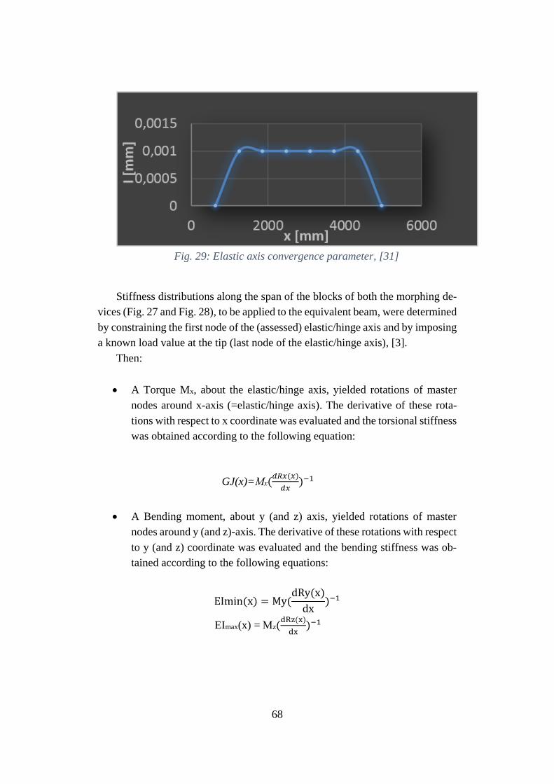
68
Fig. 29: Elastic axis convergence parameter, [31]
Stiffness distributions along the span of the blocks of both the morphing de-
vices (Fig. 27 and Fig. 28), to be applied to the equivalent beam, were determined
by constraining the first node of the (assessed) elastic/hinge axis and by imposing
a known load value at the tip (last node of the elastic/hinge axis), [3].
Then:
• A Torque Mx, about the elastic/hinge axis, yielded rotations of master
nodes around x-axis (=elastic/hinge axis). The derivative of these rota-
tions with respect to x coordinate was evaluated and the torsional stiffness
was obtained according to the following equation:
GJ(x)=Mx(𝑑𝑅𝑥(𝑥)
𝑑𝑥)−1
• A Bending moment, about y (and z) axis, yielded rotations of master
nodes around y (and z)-axis. The derivative of these rotations with respect
to y (and z) coordinate was evaluated and the bending stiffness was ob-
tained according to the following equations:
EImin(x) = My(dRy(x)
dx)−1
EImax(x) = Mz(dRz(x)
dx)−1
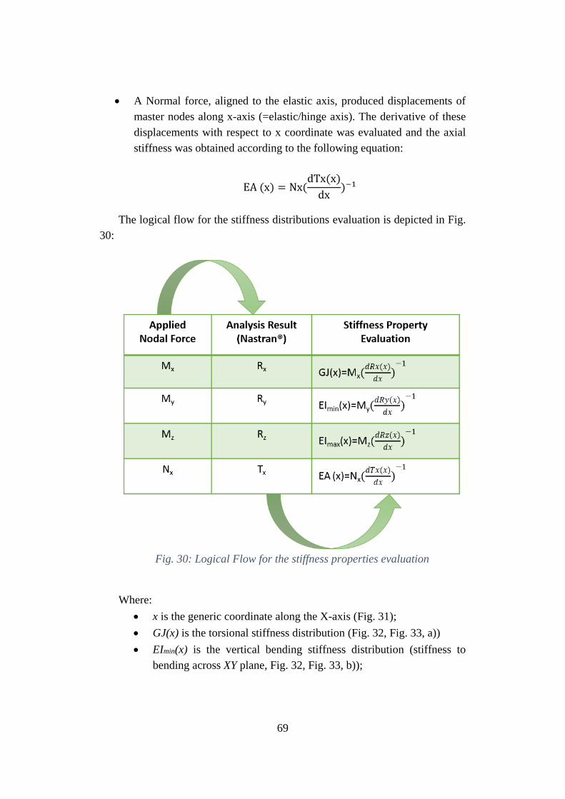
69
• A Normal force, aligned to the elastic axis, produced displacements of
master nodes along x-axis (=elastic/hinge axis). The derivative of these
displacements with respect to x coordinate was evaluated and the axial
stiffness was obtained according to the following equation:
EA (x) = Nx(dTx(x)
dx)−1
The logical flow for the stiffness distributions evaluation is depicted in Fig.
30:
Fig. 30: Logical Flow for the stiffness properties evaluation
Where:
• x is the generic coordinate along the X-axis (Fig. 31);
• GJ(x) is the torsional stiffness distribution (Fig. 32, Fig. 33, a))
• EImin(x) is the vertical bending stiffness distribution (stiffness to
bending across XY plane, Fig. 32, Fig. 33, b));
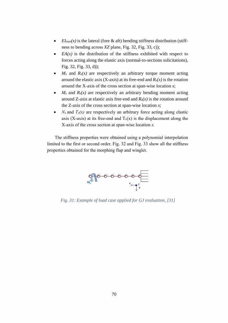
70
• EImax(x) is the lateral (fore & aft) bending stiffness distribution (stiff-
ness to bending across XZ plane, Fig. 32, Fig. 33, c));
• EA(x) is the distribution of the stiffness exhibited with respect to
forces acting along the elastic axis (normal-to-sections solicitations),
Fig. 32, Fig. 33, d));
• Mx and Rx(x) are respectively an arbitrary torque moment acting
around the elastic axis (X-axis) at its free-end and Rx(x) is the rotation
around the X-axis of the cross section at span-wise location x;
• Mz and Rz(x) are respectively an arbitrary bending moment acting
around Z-axis at elastic axis free-end and Rz(x) is the rotation around
the Z-axis of the cross section at span-wise location x;
• Nx and Tx(x) are respectively an arbitrary force acting along elastic
axis (X-axis) at its free-end and Tx(x) is the displacement along the
X-axis of the cross section at span-wise location x.
The stiffness properties were obtained using a polynomial interpolation
limited to the first or second order. Fig. 32 and Fig. 33 show all the stiffness
properties obtained for the morphing flap and winglet.
Fig. 31: Example of load case applied for GJ evaluation, [31]
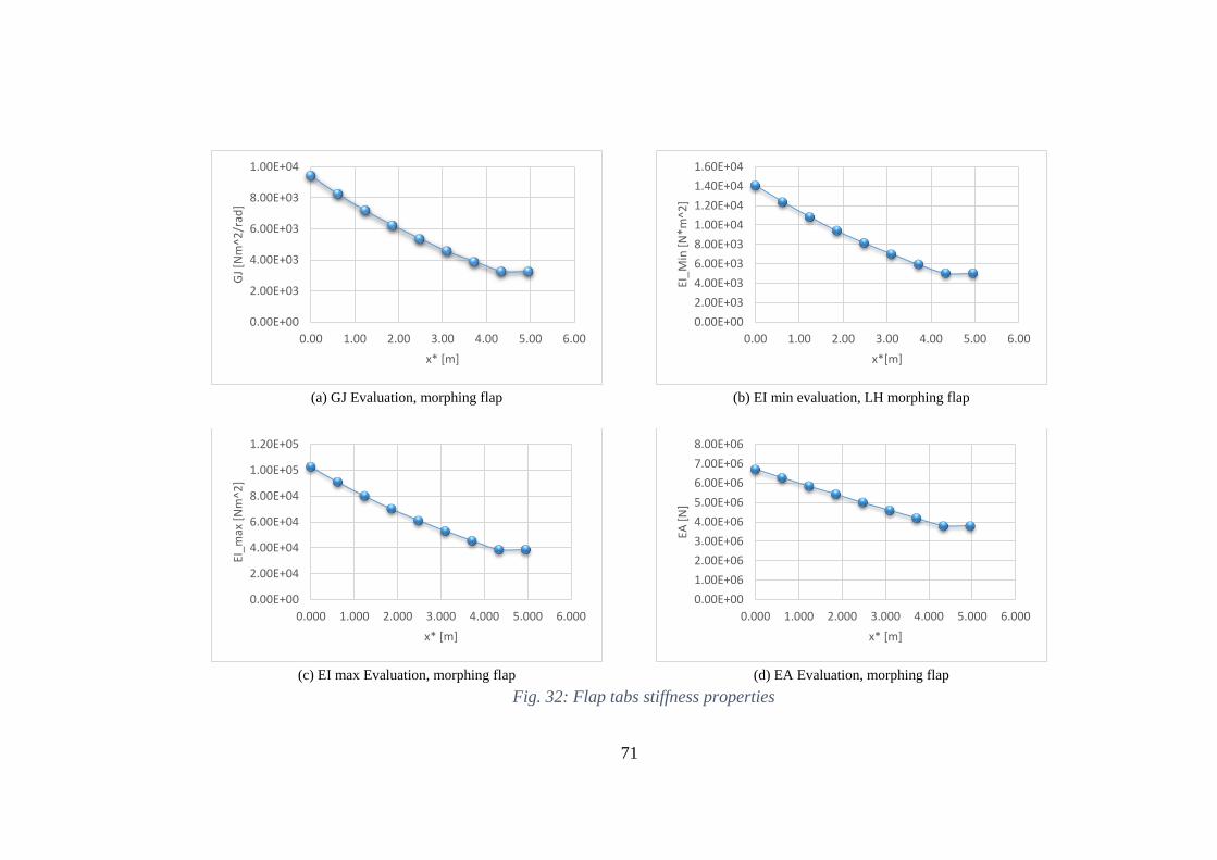
71
(a) GJ Evaluation, morphing flap
(b) EI min evaluation, LH morphing flap
(c) EI max Evaluation, morphing flap
(d) EA Evaluation, morphing flap
Fig. 32: Flap tabs stiffness properties
0.00E+00
2.00E+03
4.00E+03
6.00E+03
8.00E+03
1.00E+04
0.00 1.00 2.00 3.00 4.00 5.00 6.00
GJ
[Nm
^2/r
ad]
x* [m]
0.00E+00
2.00E+03
4.00E+03
6.00E+03
8.00E+03
1.00E+04
1.20E+04
1.40E+04
1.60E+04
0.00 1.00 2.00 3.00 4.00 5.00 6.00
EI_M
in [
N*
m^2
]
x*[m]
0.00E+00
2.00E+04
4.00E+04
6.00E+04
8.00E+04
1.00E+05
1.20E+05
0.000 1.000 2.000 3.000 4.000 5.000 6.000
EI_m
ax [
Nm
^2]
x* [m]
0.00E+00
1.00E+06
2.00E+06
3.00E+06
4.00E+06
5.00E+06
6.00E+06
7.00E+06
8.00E+06
0.000 1.000 2.000 3.000 4.000 5.000 6.000
EA [
N]
x* [m]
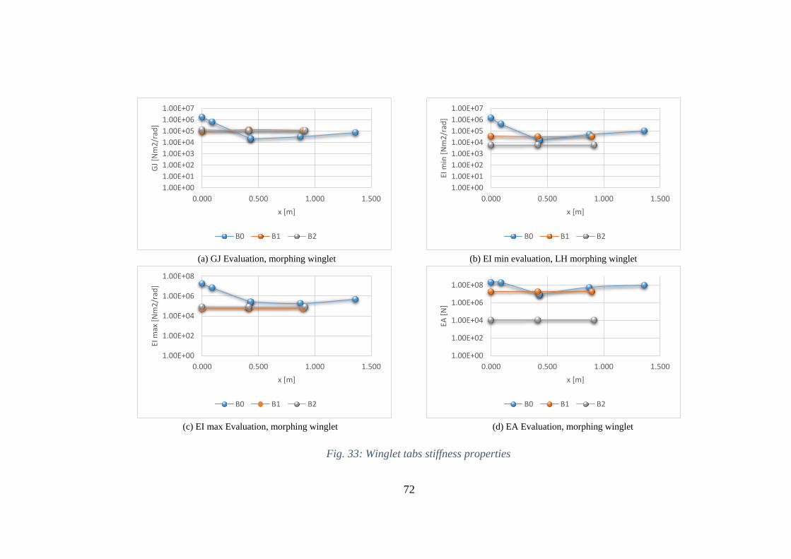
72
(a) GJ Evaluation, morphing winglet (b) EI min evaluation, LH morphing winglet
(c) EI max Evaluation, morphing winglet (d) EA Evaluation, morphing winglet
Fig. 33: Winglet tabs stiffness properties
1.00E+00
1.00E+01
1.00E+02
1.00E+03
1.00E+04
1.00E+05
1.00E+06
1.00E+07
0.000 0.500 1.000 1.500
GJ
[Nm
2/r
ad]
x [m]
B0 B1 B2
1.00E+00
1.00E+01
1.00E+02
1.00E+03
1.00E+04
1.00E+05
1.00E+06
1.00E+07
0.000 0.500 1.000 1.500
EI m
in [
Nm
2/r
ad]
x [m]
B0 B1 B2
1.00E+00
1.00E+02
1.00E+04
1.00E+06
1.00E+08
0.000 0.500 1.000 1.500
EI m
ax [
Nm
2/r
ad]
x [m]
B0 B1 B2
1.00E+00
1.00E+02
1.00E+04
1.00E+06
1.00E+08
0.000 0.500 1.000 1.500
EA [
N]
x [m]
B0 B1 B2
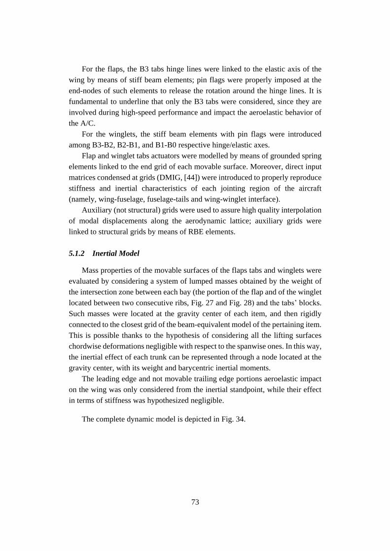
73
For the flaps, the B3 tabs hinge lines were linked to the elastic axis of the
wing by means of stiff beam elements; pin flags were properly imposed at the
end-nodes of such elements to release the rotation around the hinge lines. It is
fundamental to underline that only the B3 tabs were considered, since they are
involved during high-speed performance and impact the aeroelastic behavior of
the A/C.
For the winglets, the stiff beam elements with pin flags were introduced
among B3-B2, B2-B1, and B1-B0 respective hinge/elastic axes.
Flap and winglet tabs actuators were modelled by means of grounded spring
elements linked to the end grid of each movable surface. Moreover, direct input
matrices condensed at grids (DMIG, [44]) were introduced to properly reproduce
stiffness and inertial characteristics of each jointing region of the aircraft
(namely, wing-fuselage, fuselage-tails and wing-winglet interface).
Auxiliary (not structural) grids were used to assure high quality interpolation
of modal displacements along the aerodynamic lattice; auxiliary grids were
linked to structural grids by means of RBE elements.
5.1.2 Inertial Model
Mass properties of the movable surfaces of the flaps tabs and winglets were
evaluated by considering a system of lumped masses obtained by the weight of
the intersection zone between each bay (the portion of the flap and of the winglet
located between two consecutive ribs, Fig. 27 and Fig. 28) and the tabs’ blocks.
Such masses were located at the gravity center of each item, and then rigidly
connected to the closest grid of the beam-equivalent model of the pertaining item.
This is possible thanks to the hypothesis of considering all the lifting surfaces
chordwise deformations negligible with respect to the spanwise ones. In this way,
the inertial effect of each trunk can be represented through a node located at the
gravity center, with its weight and barycentric inertial moments.
The leading edge and not movable trailing edge portions aeroelastic impact
on the wing was only considered from the inertial standpoint, while their effect
in terms of stiffness was hypothesized negligible.
The complete dynamic model is depicted in Fig. 34.
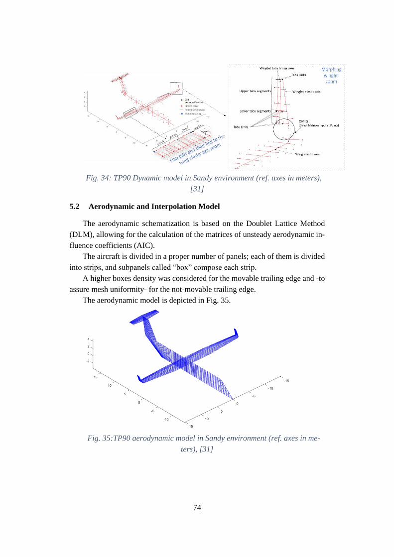
74
Fig. 34: TP90 Dynamic model in Sandy environment (ref. axes in meters),
[31]
5.2 Aerodynamic and Interpolation Model
The aerodynamic schematization is based on the Doublet Lattice Method
(DLM), allowing for the calculation of the matrices of unsteady aerodynamic in-
fluence coefficients (AIC).
The aircraft is divided in a proper number of panels; each of them is divided
into strips, and subpanels called “box” compose each strip.
A higher boxes density was considered for the movable trailing edge and -to
assure mesh uniformity- for the not-movable trailing edge.
The aerodynamic model is depicted in Fig. 35.
Fig. 35:TP90 aerodynamic model in Sandy environment (ref. axes in me-
ters), [31]
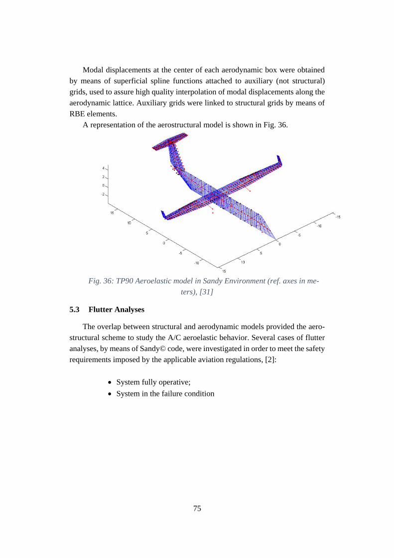
75
Modal displacements at the center of each aerodynamic box were obtained
by means of superficial spline functions attached to auxiliary (not structural)
grids, used to assure high quality interpolation of modal displacements along the
aerodynamic lattice. Auxiliary grids were linked to structural grids by means of
RBE elements.
A representation of the aerostructural model is shown in Fig. 36.
Fig. 36: TP90 Aeroelastic model in Sandy Environment (ref. axes in me-
ters), [31]
5.3 Flutter Analyses
The overlap between structural and aerodynamic models provided the aero-
structural scheme to study the A/C aeroelastic behavior. Several cases of flutter
analyses, by means of Sandy© code, were investigated in order to meet the safety
requirements imposed by the applicable aviation regulations, [2]:
• System fully operative;
• System in the failure condition
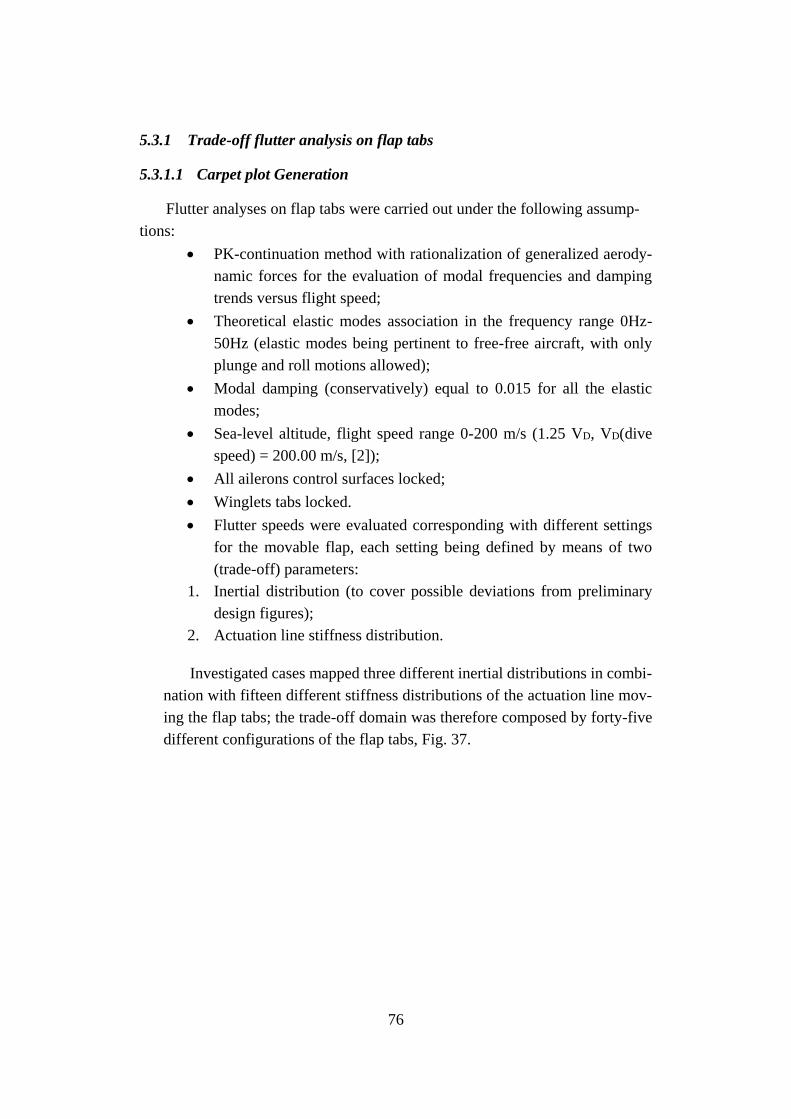
76
5.3.1 Trade-off flutter analysis on flap tabs
5.3.1.1 Carpet plot Generation
Flutter analyses on flap tabs were carried out under the following assump-
tions:
• PK-continuation method with rationalization of generalized aerody-
namic forces for the evaluation of modal frequencies and damping
trends versus flight speed;
• Theoretical elastic modes association in the frequency range 0Hz-
50Hz (elastic modes being pertinent to free-free aircraft, with only
plunge and roll motions allowed);
• Modal damping (conservatively) equal to 0.015 for all the elastic
modes;
• Sea-level altitude, flight speed range 0-200 m/s (1.25 VD, VD(dive
speed) = 200.00 m/s, [2]);
• All ailerons control surfaces locked;
• Winglets tabs locked.
• Flutter speeds were evaluated corresponding with different settings
for the movable flap, each setting being defined by means of two
(trade-off) parameters:
1. Inertial distribution (to cover possible deviations from preliminary
design figures);
2. Actuation line stiffness distribution.
Investigated cases mapped three different inertial distributions in combi-
nation with fifteen different stiffness distributions of the actuation line mov-
ing the flap tabs; the trade-off domain was therefore composed by forty-five
different configurations of the flap tabs, Fig. 37.
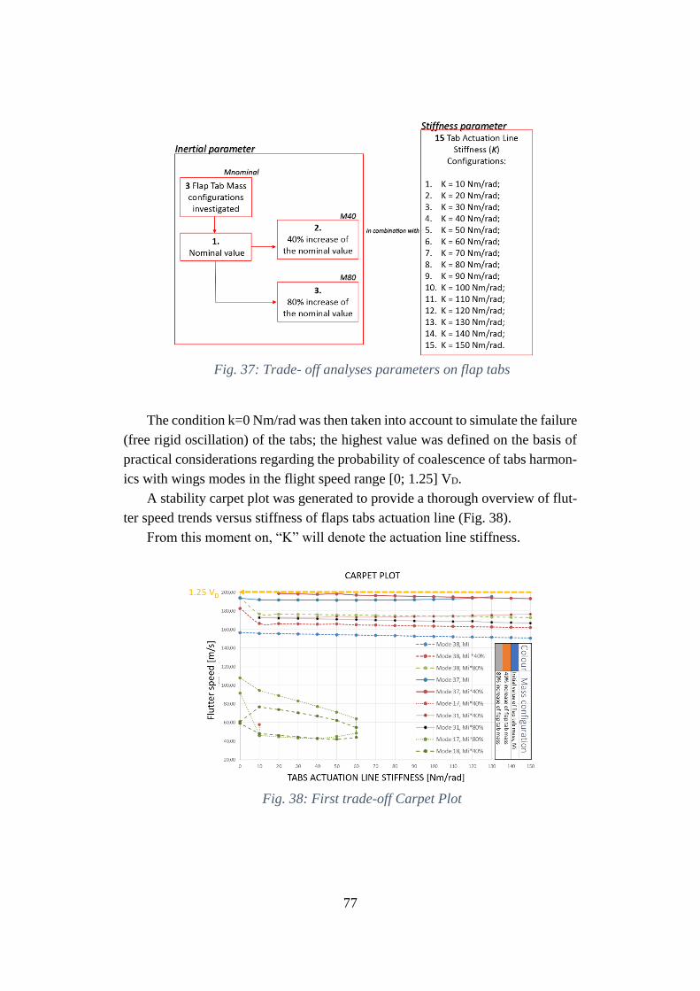
77
Fig. 37: Trade- off analyses parameters on flap tabs
The condition k=0 Nm/rad was then taken into account to simulate the failure
(free rigid oscillation) of the tabs; the highest value was defined on the basis of
practical considerations regarding the probability of coalescence of tabs harmon-
ics with wings modes in the flight speed range [0; 1.25] VD.
A stability carpet plot was generated to provide a thorough overview of flut-
ter speed trends versus stiffness of flaps tabs actuation line (Fig. 38).
From this moment on, “K” will denote the actuation line stiffness.
Fig. 38: First trade-off Carpet Plot
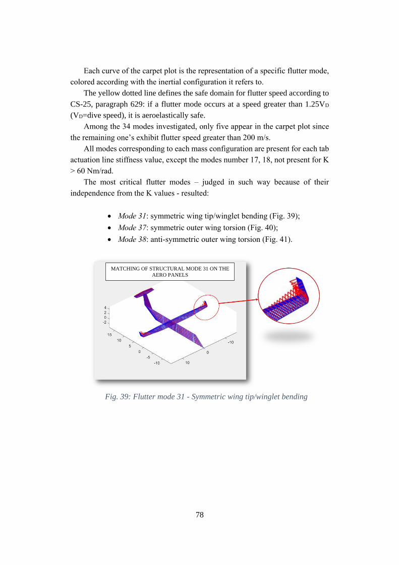
78
Each curve of the carpet plot is the representation of a specific flutter mode,
colored according with the inertial configuration it refers to.
The yellow dotted line defines the safe domain for flutter speed according to
CS-25, paragraph 629: if a flutter mode occurs at a speed greater than 1.25VD
(VD=dive speed), it is aeroelastically safe.
Among the 34 modes investigated, only five appear in the carpet plot since
the remaining one’s exhibit flutter speed greater than 200 m/s.
All modes corresponding to each mass configuration are present for each tab
actuation line stiffness value, except the modes number 17, 18, not present for K
> 60 Nm/rad.
The most critical flutter modes – judged in such way because of their
independence from the K values - resulted:
• Mode 31: symmetric wing tip/winglet bending (Fig. 39);
• Mode 37: symmetric outer wing torsion (Fig. 40);
• Mode 38: anti-symmetric outer wing torsion (Fig. 41).
Fig. 39: Flutter mode 31 - Symmetric wing tip/winglet bending
MATCHING OF STRUCTURAL MODE 31 ON THE
AERO PANELS
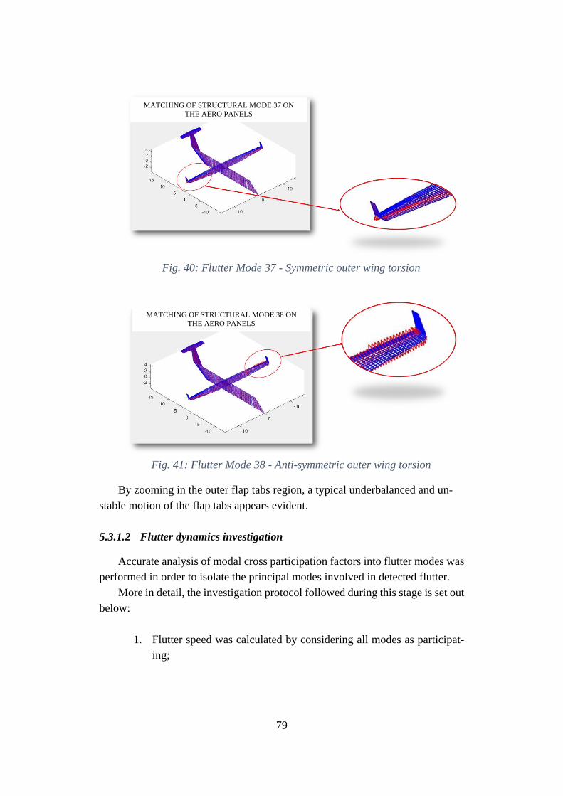
79
Fig. 40: Flutter Mode 37 - Symmetric outer wing torsion
Fig. 41: Flutter Mode 38 - Anti-symmetric outer wing torsion
By zooming in the outer flap tabs region, a typical underbalanced and un-
stable motion of the flap tabs appears evident.
5.3.1.2 Flutter dynamics investigation
Accurate analysis of modal cross participation factors into flutter modes was
performed in order to isolate the principal modes involved in detected flutter.
More in detail, the investigation protocol followed during this stage is set out
below:
1. Flutter speed was calculated by considering all modes as participat-
ing;
MATCHING OF STRUCTURAL MODE 37 ON
THE AERO PANELS
MATCHING OF STRUCTURAL MODE 38 ON
THE AERO PANELS
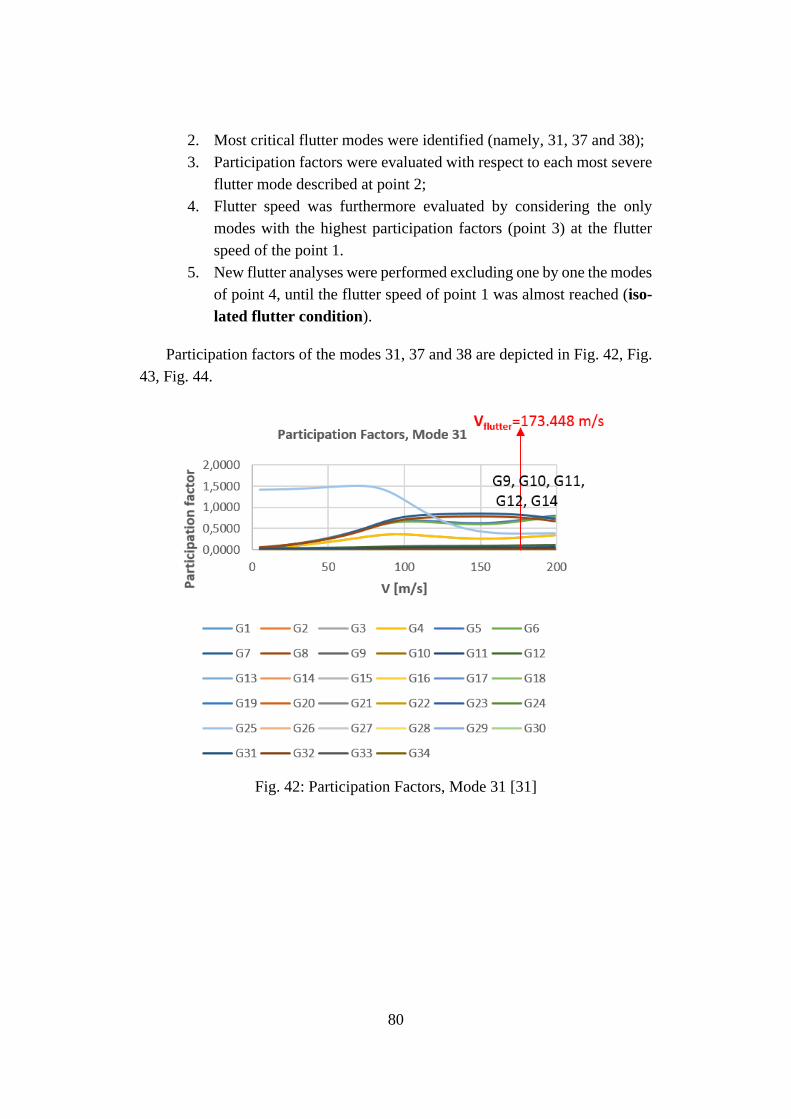
80
2. Most critical flutter modes were identified (namely, 31, 37 and 38);
3. Participation factors were evaluated with respect to each most severe
flutter mode described at point 2;
4. Flutter speed was furthermore evaluated by considering the only
modes with the highest participation factors (point 3) at the flutter
speed of the point 1.
5. New flutter analyses were performed excluding one by one the modes
of point 4, until the flutter speed of point 1 was almost reached (iso-
lated flutter condition).
Participation factors of the modes 31, 37 and 38 are depicted in Fig. 42, Fig.
43, Fig. 44.
Fig. 42: Participation Factors, Mode 31 [31]
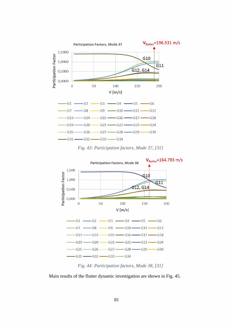
81
Fig. 43: Participation factors, Mode 37, [31]
Fig. 44: Participation factors, Mode 38, [31]
Main results of the flutter dynamic investigation are shown in Fig. 45.
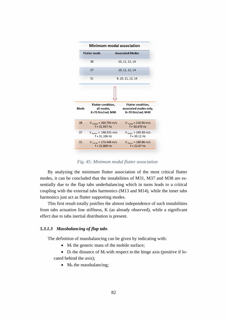
82
Fig. 45: Minimum modal flutter association
By analysing the minimum flutter association of the most critical flutter
modes, it can be concluded that the instabilities of M31, M37 and M38 are es-
sentially due to the flap tabs underbalancing which in turns leads to a critical
coupling with the external tabs harmonics (M13 and M14), while the inner tabs
harmonics just act as flutter supporting modes.
This first result totally justifies the almost independence of such instabilities
from tabs actuation line stiffness, K (as already observed), while a significant
effect due to tabs inertial distribution is present.
5.3.1.3 Massbalancing of flap tabs
The definition of massbalancing can be given by indicating with:
• Mi the generic mass of the mobile surface;
• Di the distance of Mi with respect to the hinge axis (positive if lo-
cated behind the axis);
• Mb the massbalancing;
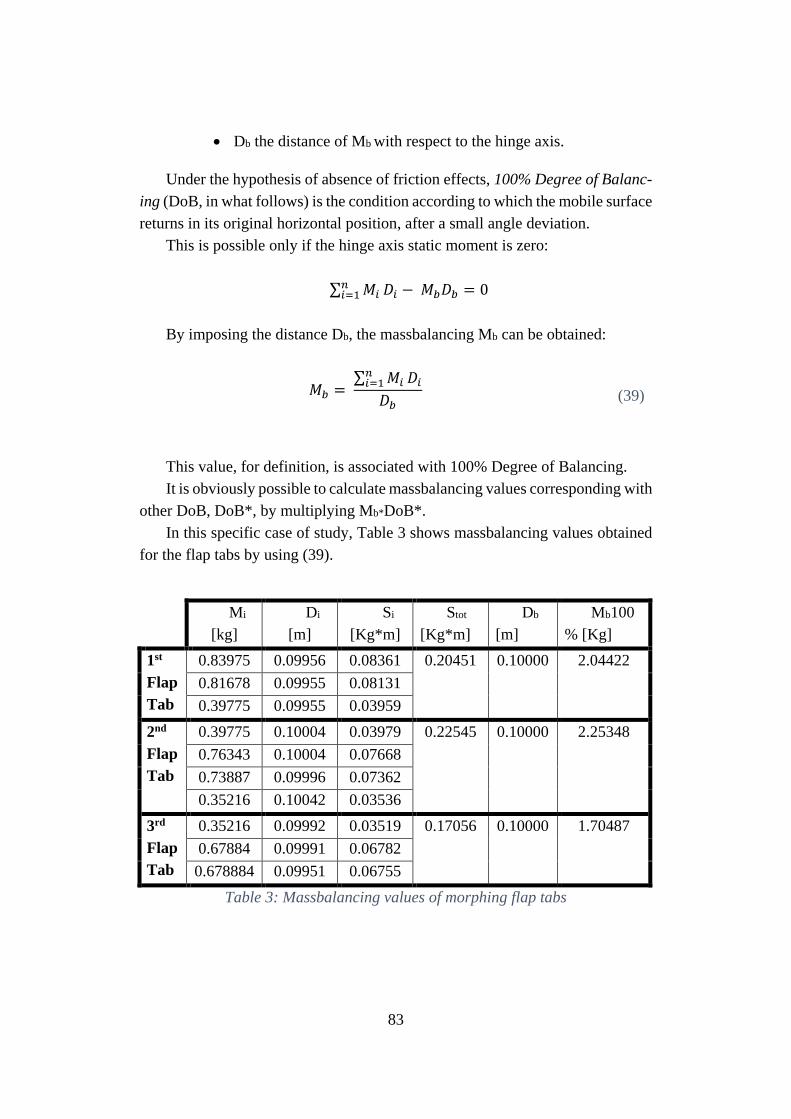
83
• Db the distance of Mb with respect to the hinge axis.
Under the hypothesis of absence of friction effects, 100% Degree of Balanc-
ing (DoB, in what follows) is the condition according to which the mobile surface
returns in its original horizontal position, after a small angle deviation.
This is possible only if the hinge axis static moment is zero:
∑ 𝑀𝑖𝑛𝑖=1 𝐷𝑖 − 𝑀𝑏𝐷𝑏 = 0
By imposing the distance Db, the massbalancing Mb can be obtained:
𝑀𝑏 = ∑ 𝑀𝑖
𝑛𝑖=1 𝐷𝑖
𝐷𝑏
(39)
This value, for definition, is associated with 100% Degree of Balancing.
It is obviously possible to calculate massbalancing values corresponding with
other DoB, DoB*, by multiplying Mb*DoB*.
In this specific case of study, Table 3 shows massbalancing values obtained
for the flap tabs by using (39).
Mi
[kg]
Di
[m]
Si
[Kg*m]
Stot
[Kg*m]
Db
[m]
Mb100
% [Kg]
1st
Flap
Tab
0.83975 0.09956 0.08361 0.20451 0.10000 2.04422
0.81678 0.09955 0.08131
0.39775 0.09955 0.03959
2nd
Flap
Tab
0.39775 0.10004 0.03979 0.22545 0.10000 2.25348
0.76343 0.10004 0.07668
0.73887 0.09996 0.07362
0.35216 0.10042 0.03536
3rd
Flap
Tab
0.35216 0.09992 0.03519 0.17056 0.10000 1.70487
0.67884 0.09991 0.06782
0.678884 0.09951 0.06755
Table 3: Massbalancing values of morphing flap tabs
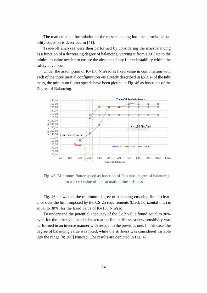
84
The mathematical formulation of the massbalancing into the aeroelastic sta-
bility equation is described in [41].
Trade-off analyses were then performed by considering the massbalancing
as a function of a decreasing degree of balancing, varying it from 100% up to the
minimum value needed to ensure the absence of any flutter instability within the
safety envelope.
Under the assumption of K=150 Nm/rad as fixed value in combination with
each of the three inertial configuration -as already described in §5.3.1- of the tabs
mass, the minimum flutter speeds have been plotted in Fig. 46 as functions of the
Degree of Balancing.
Fig. 46: Minimum flutter speed as function of flap tabs degree of balancing,
for a fixed value of tabs actuation line stiffness
Fig. 46 shows that the minimum degree of balancing ensuring flutter clear-
ance over the limit imposed by the CS-25 requirements (black horizontal line) is
equal to 30%, for the fixed value of K=150 Nm/rad.
To understand the potential adequacy of the DoB value found equal to 30%
even for the other values of tabs actuation line stiffness, a new sensitivity was
performed in an inverse manner with respect to the previous one. In this case, the
degree of balancing value was fixed, while the stiffness was considered variable
into the range [0; 200] Nm/rad. The results are depicted in Fig. 47.
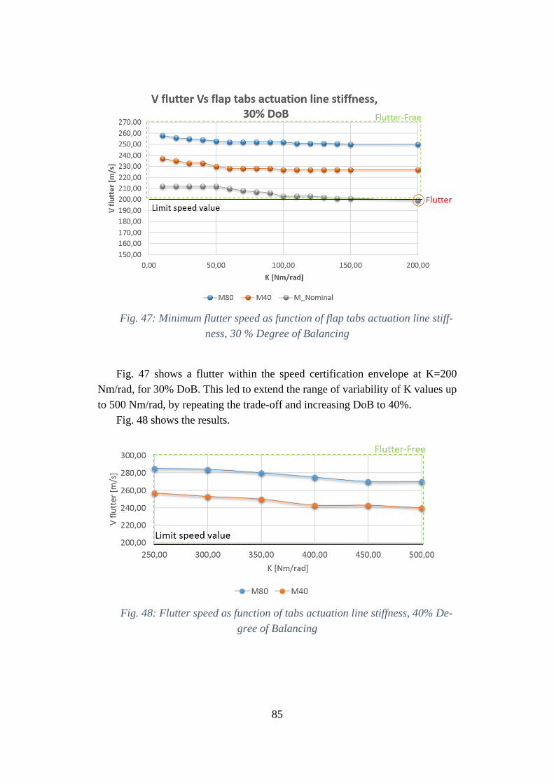
85
Fig. 47: Minimum flutter speed as function of flap tabs actuation line stiff-
ness, 30 % Degree of Balancing
Fig. 47 shows a flutter within the speed certification envelope at K=200
Nm/rad, for 30% DoB. This led to extend the range of variability of K values up
to 500 Nm/rad, by repeating the trade-off and increasing DoB to 40%.
Fig. 48 shows the results.
Fig. 48: Flutter speed as function of tabs actuation line stiffness, 40% De-
gree of Balancing
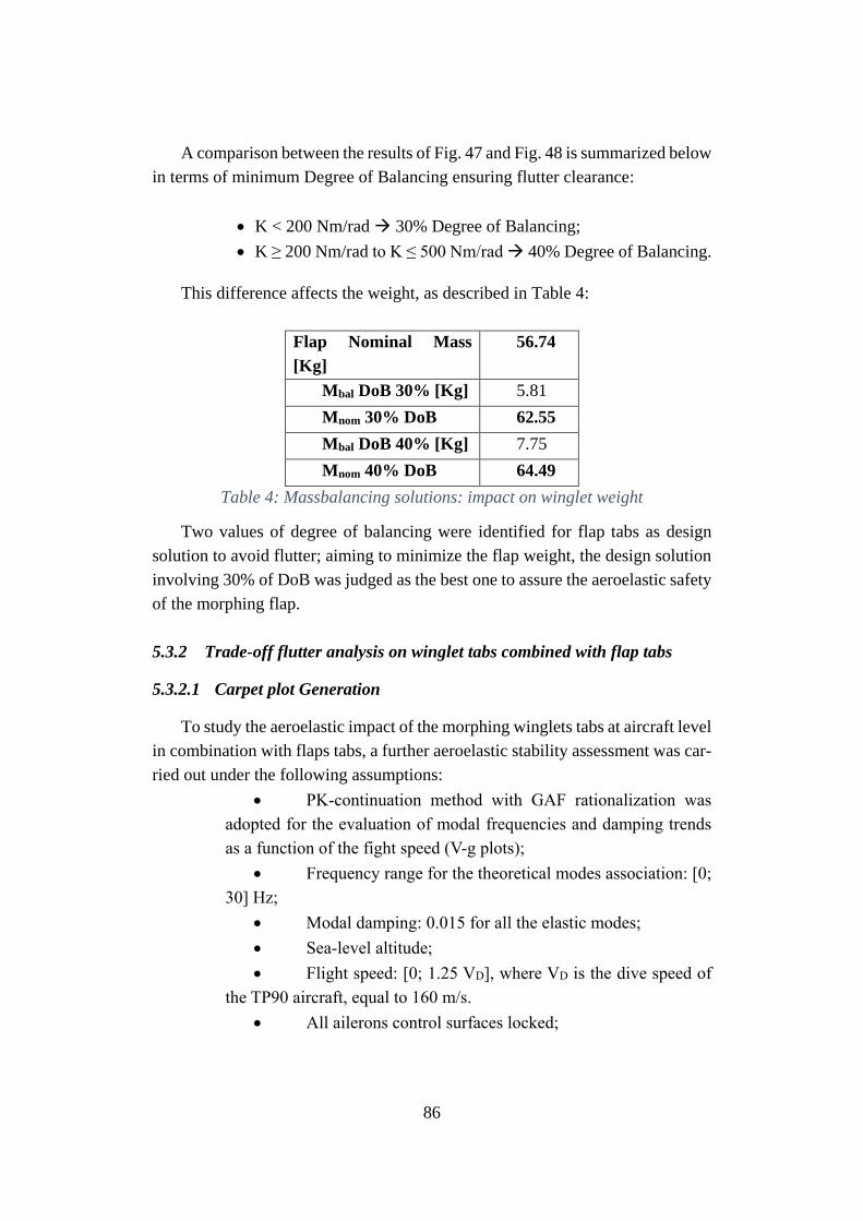
86
A comparison between the results of Fig. 47 and Fig. 48 is summarized below
in terms of minimum Degree of Balancing ensuring flutter clearance:
• K < 200 Nm/rad 30% Degree of Balancing;
• K ≥ 200 Nm/rad to K ≤ 500 Nm/rad 40% Degree of Balancing.
This difference affects the weight, as described in Table 4:
Flap Nominal Mass
[Kg]
56.74
Mbal DoB 30% [Kg] 5.81
Mnom 30% DoB 62.55
Mbal DoB 40% [Kg] 7.75
Mnom 40% DoB 64.49
Table 4: Massbalancing solutions: impact on winglet weight
Two values of degree of balancing were identified for flap tabs as design
solution to avoid flutter; aiming to minimize the flap weight, the design solution
involving 30% of DoB was judged as the best one to assure the aeroelastic safety
of the morphing flap.
5.3.2 Trade-off flutter analysis on winglet tabs combined with flap tabs
5.3.2.1 Carpet plot Generation
To study the aeroelastic impact of the morphing winglets tabs at aircraft level
in combination with flaps tabs, a further aeroelastic stability assessment was car-
ried out under the following assumptions:
• PK-continuation method with GAF rationalization was
adopted for the evaluation of modal frequencies and damping trends
as a function of the fight speed (V-g plots);
• Frequency range for the theoretical modes association: [0;
30] Hz;
• Modal damping: 0.015 for all the elastic modes;
• Sea-level altitude;
• Flight speed: [0; 1.25 VD], where VD is the dive speed of
the TP90 aircraft, equal to 160 m/s.
• All ailerons control surfaces locked;
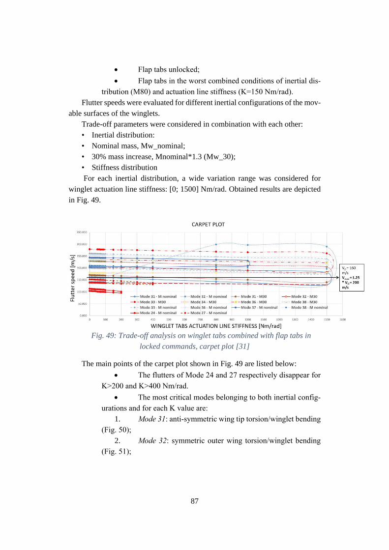
87
• Flap tabs unlocked;
• Flap tabs in the worst combined conditions of inertial dis-
tribution (M80) and actuation line stiffness (K=150 Nm/rad).
Flutter speeds were evaluated for different inertial configurations of the mov-
able surfaces of the winglets.
Trade-off parameters were considered in combination with each other:
• Inertial distribution:
• Nominal mass, Mw_nominal;
• 30% mass increase, Mnominal*1.3 (Mw_30);
• Stiffness distribution
For each inertial distribution, a wide variation range was considered for
winglet actuation line stiffness: [0; 1500] Nm/rad. Obtained results are depicted
in Fig. 49.
Fig. 49: Trade-off analysis on winglet tabs combined with flap tabs in
locked commands, carpet plot [31]
The main points of the carpet plot shown in Fig. 49 are listed below:
• The flutters of Mode 24 and 27 respectively disappear for
K>200 and K>400 Nm/rad.
• The most critical modes belonging to both inertial config-
urations and for each K value are:
1. Mode 31: anti-symmetric wing tip torsion/winglet bending
(Fig. 50);
2. Mode 32: symmetric outer wing torsion/winglet bending
(Fig. 51);
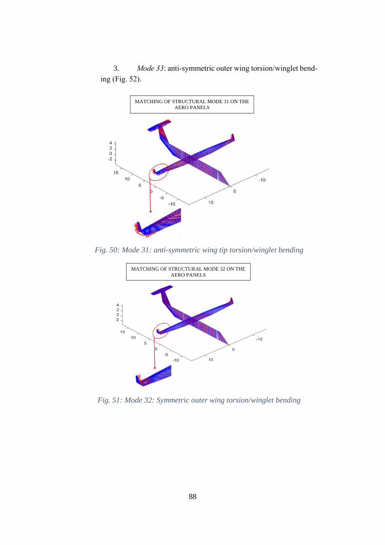
88
3. Mode 33: anti-symmetric outer wing torsion/winglet bend-
ing (Fig. 52).
Fig. 50: Mode 31: anti-symmetric wing tip torsion/winglet bending
Fig. 51: Mode 32: Symmetric outer wing torsion/winglet bending
MATCHING OF STRUCTURAL MODE 31 ON THE
AERO PANELS
MATCHING OF STRUCTURAL MODE 32 ON THE
AERO PANELS
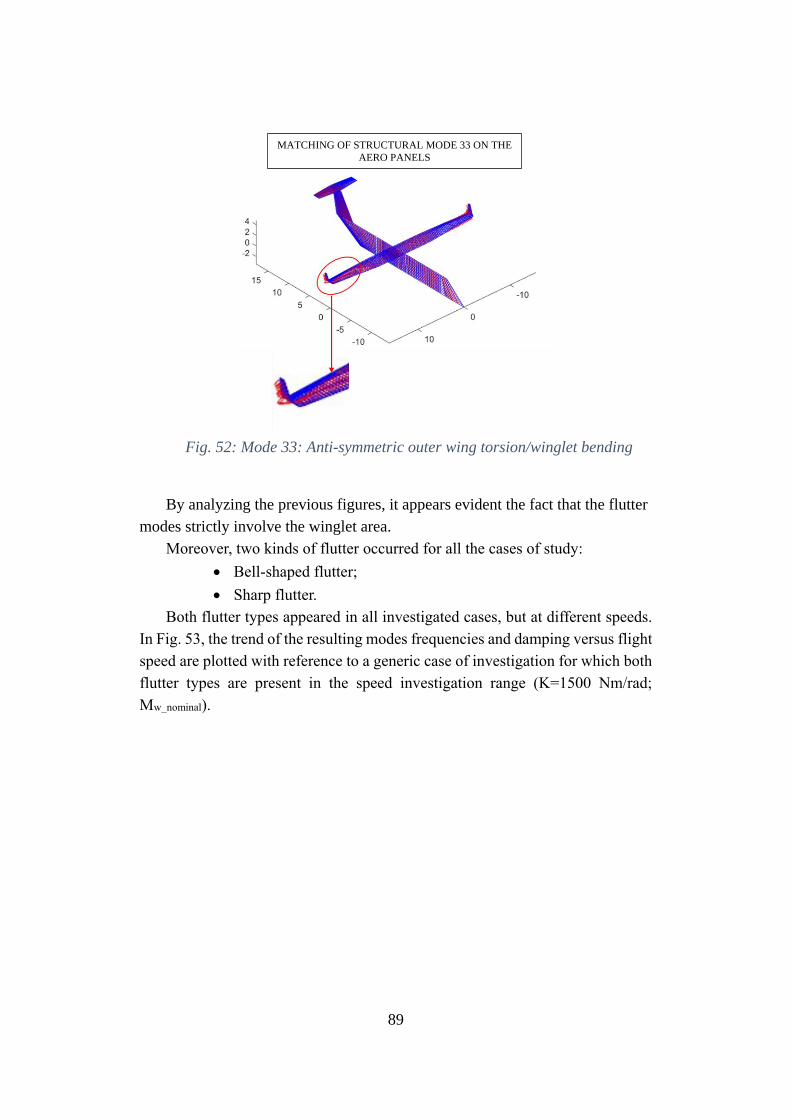
89
Fig. 52: Mode 33: Anti-symmetric outer wing torsion/winglet bending
By analyzing the previous figures, it appears evident the fact that the flutter
modes strictly involve the winglet area.
Moreover, two kinds of flutter occurred for all the cases of study:
• Bell-shaped flutter;
• Sharp flutter.
Both flutter types appeared in all investigated cases, but at different speeds.
In Fig. 53, the trend of the resulting modes frequencies and damping versus flight
speed are plotted with reference to a generic case of investigation for which both
flutter types are present in the speed investigation range (K=1500 Nm/rad;
Mw_nominal).
MATCHING OF STRUCTURAL MODE 33 ON THE
AERO PANELS
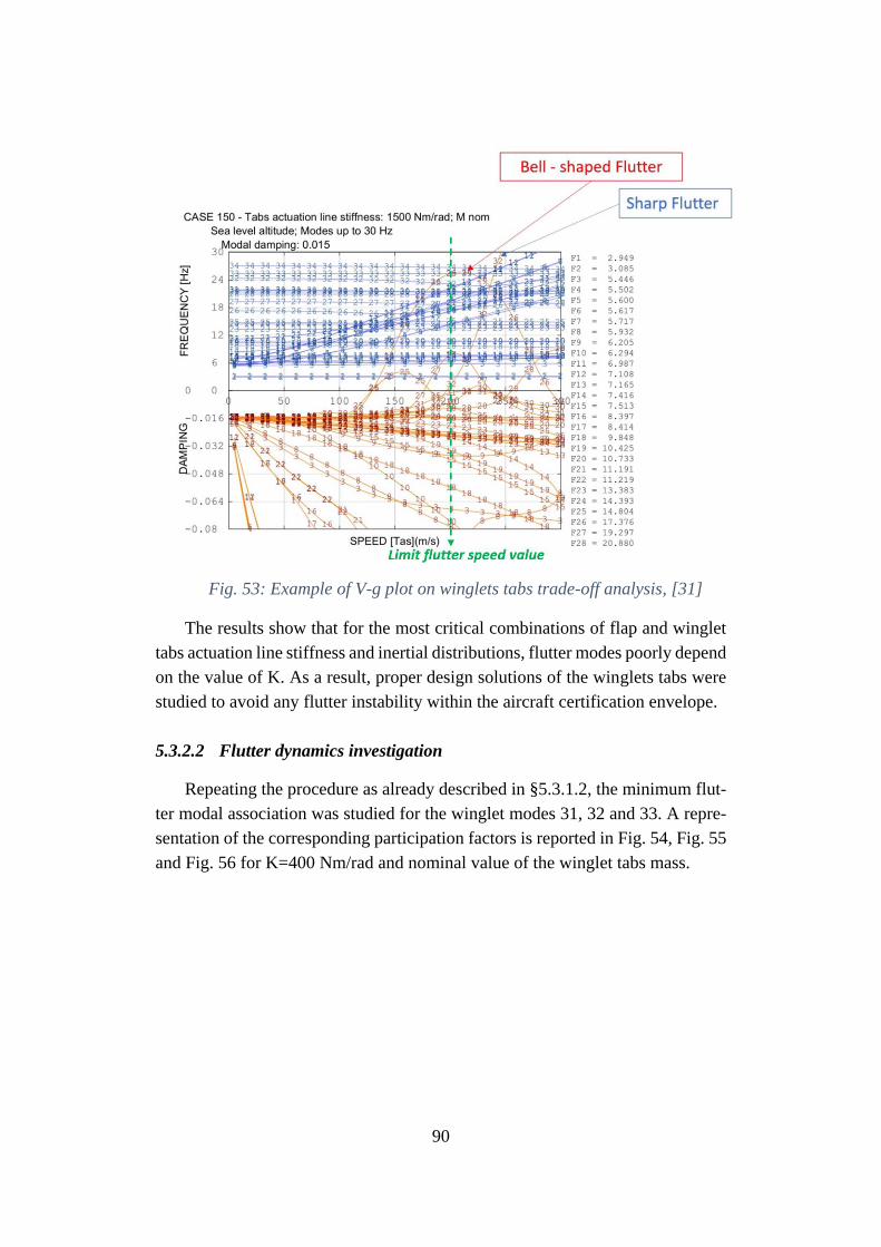
90
Fig. 53: Example of V-g plot on winglets tabs trade-off analysis, [31]
The results show that for the most critical combinations of flap and winglet
tabs actuation line stiffness and inertial distributions, flutter modes poorly depend
on the value of K. As a result, proper design solutions of the winglets tabs were
studied to avoid any flutter instability within the aircraft certification envelope.
5.3.2.2 Flutter dynamics investigation
Repeating the procedure as already described in §5.3.1.2, the minimum flut-
ter modal association was studied for the winglet modes 31, 32 and 33. A repre-
sentation of the corresponding participation factors is reported in Fig. 54, Fig. 55
and Fig. 56 for K=400 Nm/rad and nominal value of the winglet tabs mass.
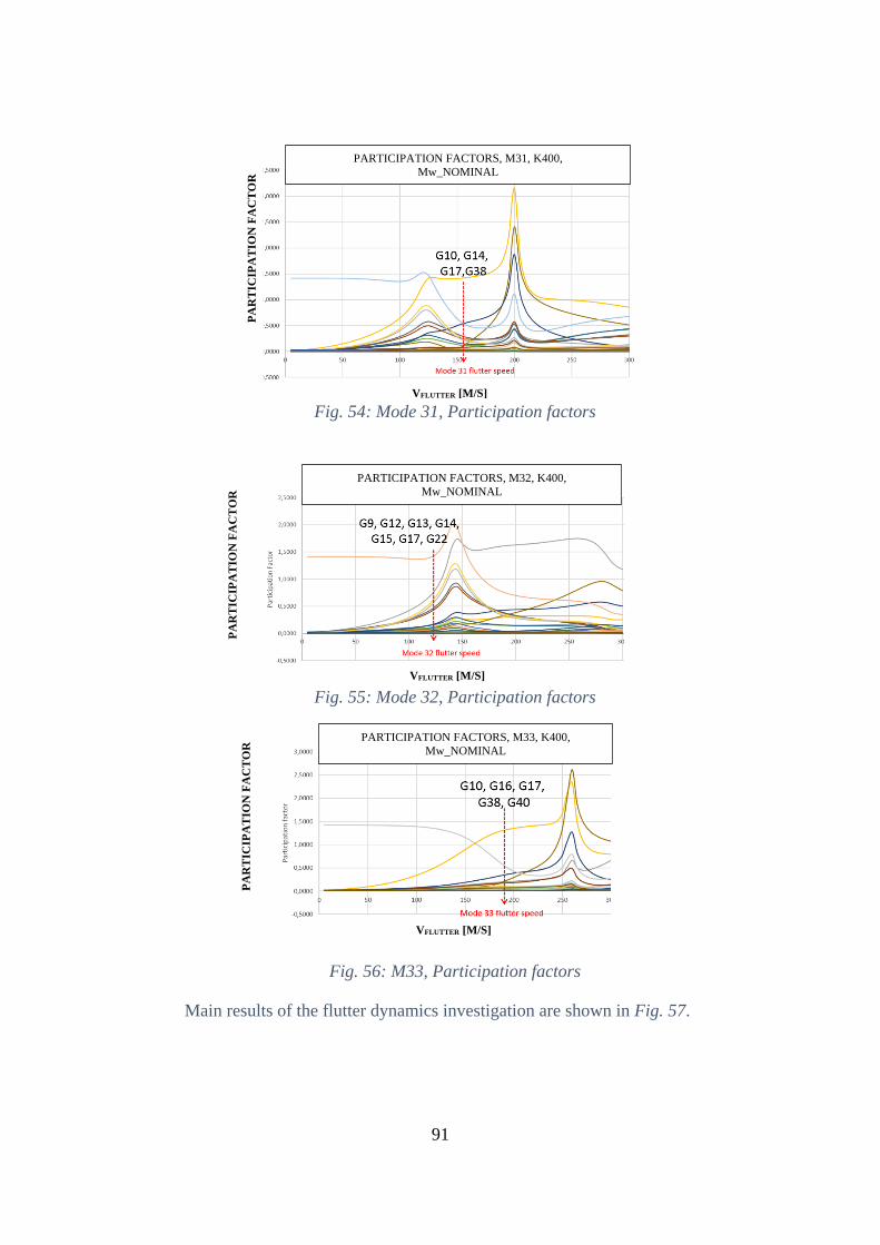
91
Fig. 54: Mode 31, Participation factors
Fig. 55: Mode 32, Participation factors
Fig. 56: M33, Participation factors
Main results of the flutter dynamics investigation are shown in Fig. 57.
PARTICIPATION FACTORS, M31, K400,
Mw_NOMINAL
VFLUTTER [M/S]
PA
RT
ICIP
AT
ION
FA
CT
OR
PA
RT
ICIP
AT
ION
FA
CT
OR
VFLUTTER [M/S]
PARTICIPATION FACTORS, M32, K400,
Mw_NOMINAL
PARTICIPATION FACTORS, M33, K400,
Mw_NOMINAL
VFLUTTER [M/S]
PA
RT
ICIP
AT
ION
FA
CT
OR
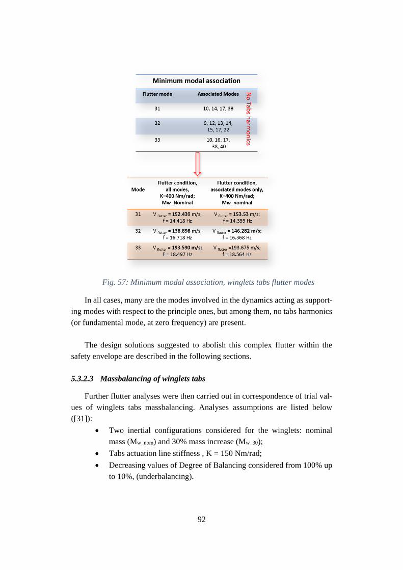
92
Fig. 57: Minimum modal association, winglets tabs flutter modes
In all cases, many are the modes involved in the dynamics acting as support-
ing modes with respect to the principle ones, but among them, no tabs harmonics
(or fundamental mode, at zero frequency) are present.
The design solutions suggested to abolish this complex flutter within the
safety envelope are described in the following sections.
5.3.2.3 Massbalancing of winglets tabs
Further flutter analyses were then carried out in correspondence of trial val-
ues of winglets tabs massbalancing. Analyses assumptions are listed below
([31]):
• Two inertial configurations considered for the winglets: nominal
mass (Mw_nom) and 30% mass increase (Mw_30);
• Tabs actuation line stiffness , K = 150 Nm/rad;
• Decreasing values of Degree of Balancing considered from 100% up
to 10%, (underbalancing).
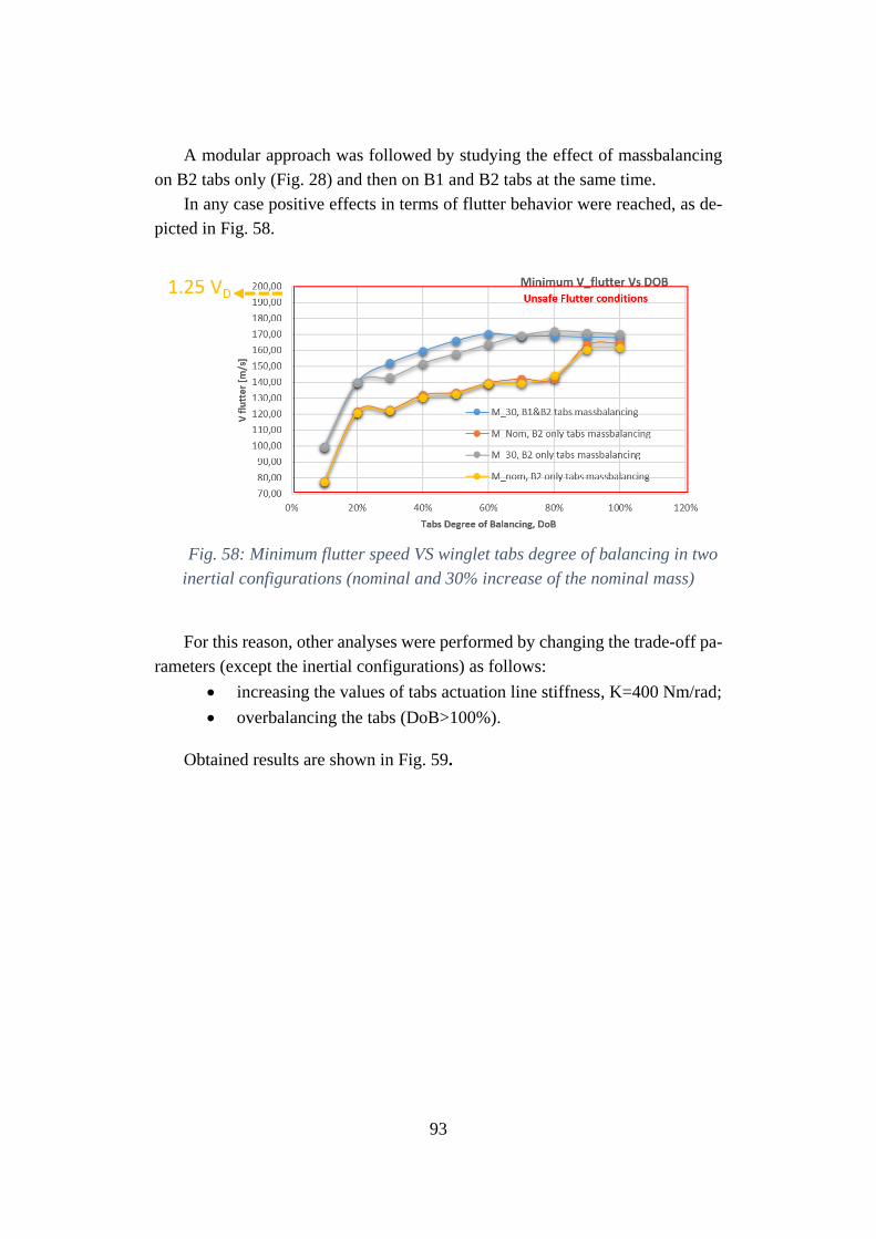
93
A modular approach was followed by studying the effect of massbalancing
on B2 tabs only (Fig. 28) and then on B1 and B2 tabs at the same time.
In any case positive effects in terms of flutter behavior were reached, as de-
picted in Fig. 58.
Fig. 58: Minimum flutter speed VS winglet tabs degree of balancing in two
inertial configurations (nominal and 30% increase of the nominal mass)
For this reason, other analyses were performed by changing the trade-off pa-
rameters (except the inertial configurations) as follows:
• increasing the values of tabs actuation line stiffness, K=400 Nm/rad;
• overbalancing the tabs (DoB>100%).
Obtained results are shown in Fig. 59.
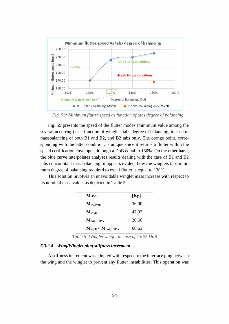
94
Fig. 59: Minimum flutter speed as function of tabs degree of balancing.
Fig. 59 presents the speed of the flutter modes (minimum value among the
several occurring) as a function of winglets tabs degree of balancing, in case of
massbalancing of both B1 and B2, and B2 tabs only. The orange point, corre-
sponding with the latter condition, is unique since it returns a flutter within the
speed certification envelope, although a DoB equal to 150%. On the other hand,
the blue curve interpolates analyses results dealing with the case of B1 and B2
tabs concomitant massbalancing: it appears evident how the winglets tabs mini-
mum degree of balancing required to expel flutter is equal to 130%.
This solution involves an unavoidable winglet mass increase with respect to
its nominal mass value, as depicted in Table 5
Mass [Kg]
Mw_Nom 36.90
Mw_30 47.97
Mbal_130% 20.66
Mw_30+ Mbal_130% 68.63
Table 5: Winglet weight in case of 130% DoB
5.3.2.4 Wing/Winglet plug stiffness increment
A stiffness increment was adopted with respect to the interface plug between
the wing and the winglet to prevent any flutter instabilities. This operation was
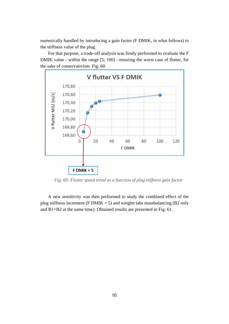
95
numerically handled by introducing a gain factor (F DMIK, in what follows) to
the stiffness value of the plug.
For that purpose, a trade-off analysis was firstly performed to evaluate the F
DMIK value - within the range [5; 100] - ensuring the worst case of flutter, for
the sake of conservativism. Fig. 60.
Fig. 60: Flutter speed trend as a function of plug stiffness gain factor
A new sensitivity was then performed to study the combined effect of the
plug stiffness increment (F DMIK = 5) and winglet tabs massbalancing (B2 only
and B1+B2 at the same time). Obtained results are presented in Fig. 61.
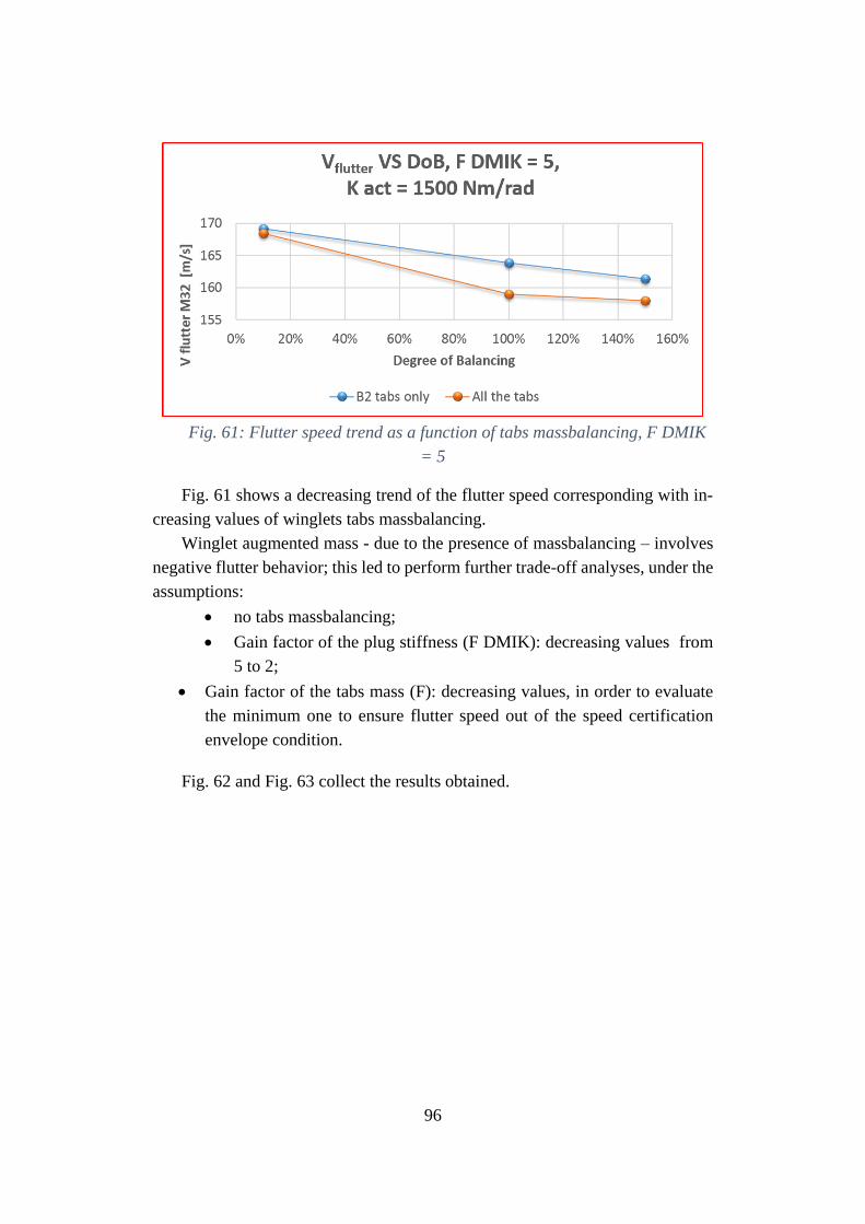
96
Fig. 61: Flutter speed trend as a function of tabs massbalancing, F DMIK
= 5
Fig. 61 shows a decreasing trend of the flutter speed corresponding with in-
creasing values of winglets tabs massbalancing.
Winglet augmented mass - due to the presence of massbalancing – involves
negative flutter behavior; this led to perform further trade-off analyses, under the
assumptions:
• no tabs massbalancing;
• Gain factor of the plug stiffness (F DMIK): decreasing values from
5 to 2;
• Gain factor of the tabs mass (F): decreasing values, in order to evaluate
the minimum one to ensure flutter speed out of the speed certification
envelope condition.
Fig. 62 and Fig. 63 collect the results obtained.
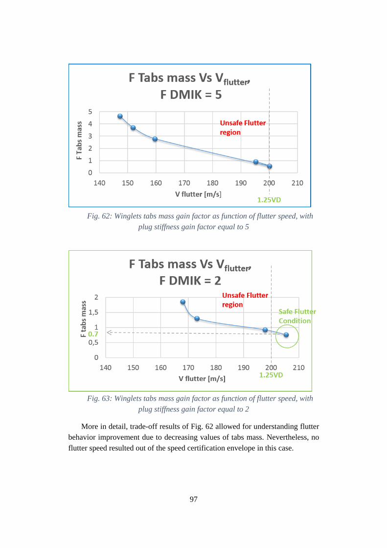
97
Fig. 62: Winglets tabs mass gain factor as function of flutter speed, with
plug stiffness gain factor equal to 5
Fig. 63: Winglets tabs mass gain factor as function of flutter speed, with
plug stiffness gain factor equal to 2
More in detail, trade-off results of Fig. 62 allowed for understanding flutter
behavior improvement due to decreasing values of tabs mass. Nevertheless, no
flutter speed resulted out of the speed certification envelope in this case.
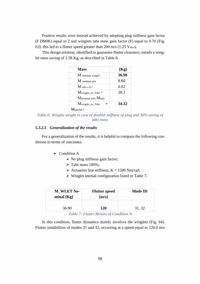
98
Positive results were instead achieved by adopting plug stiffness gain factor
(F DMIK) equal to 2 and winglets tabs mass gain factor (F) equal to 0.70 (Fig.
63): this led to a flutter speed greater than 200 m/s (1.25 Vdive).
This design solution, identified to guarantee flutter clearance, entails a wing-
let mass saving of 2.58 Kg, as described in Table 6.
Mass [Kg]
M nominal winglet 36.90
M nominal tabs 8.60
M tabs x 0.7 6.02
Mwinglet_no_Tabs =
Mnominal wlet-Mtabs
28.3
Mwinglet_no_Tabs +
MtabsX0.7
34.32
Table 6: Winglet weight in case of doublet stiffness of plug and 30% saving of
tabs mass
5.3.2.5 Generalization of the results
For a generalization of the results, it is helpful to compare the following con-
ditions in terms of outcomes:
• Condition A
➢ No plug stiffness gain factor;
➢ Tabs mass 100%;
➢ Actuation line stiffness, K = 1500 Nm/rad;
➢ Winglet inertial configuration listed in Table 7.
M_WLET No-
minal [Kg]
Flutter speed
[m/s]
Mode ID
36.90
120
31, 32
Table 7: Flutter Results of Condition A
In this condition, flutter dynamics mainly involves the winglets (Fig. 64).
Flutter instabilities of modes 31 and 32, occurring at a speed equal to 120.0 m/s
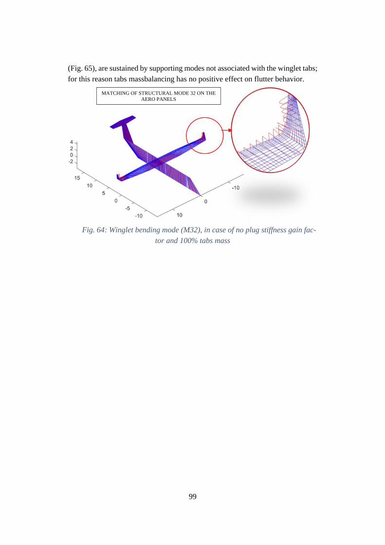
99
(Fig. 65), are sustained by supporting modes not associated with the winglet tabs;
for this reason tabs massbalancing has no positive effect on flutter behavior.
Fig. 64: Winglet bending mode (M32), in case of no plug stiffness gain fac-
tor and 100% tabs mass
MATCHING OF STRUCTURAL MODE 32 ON THE
AERO PANELS
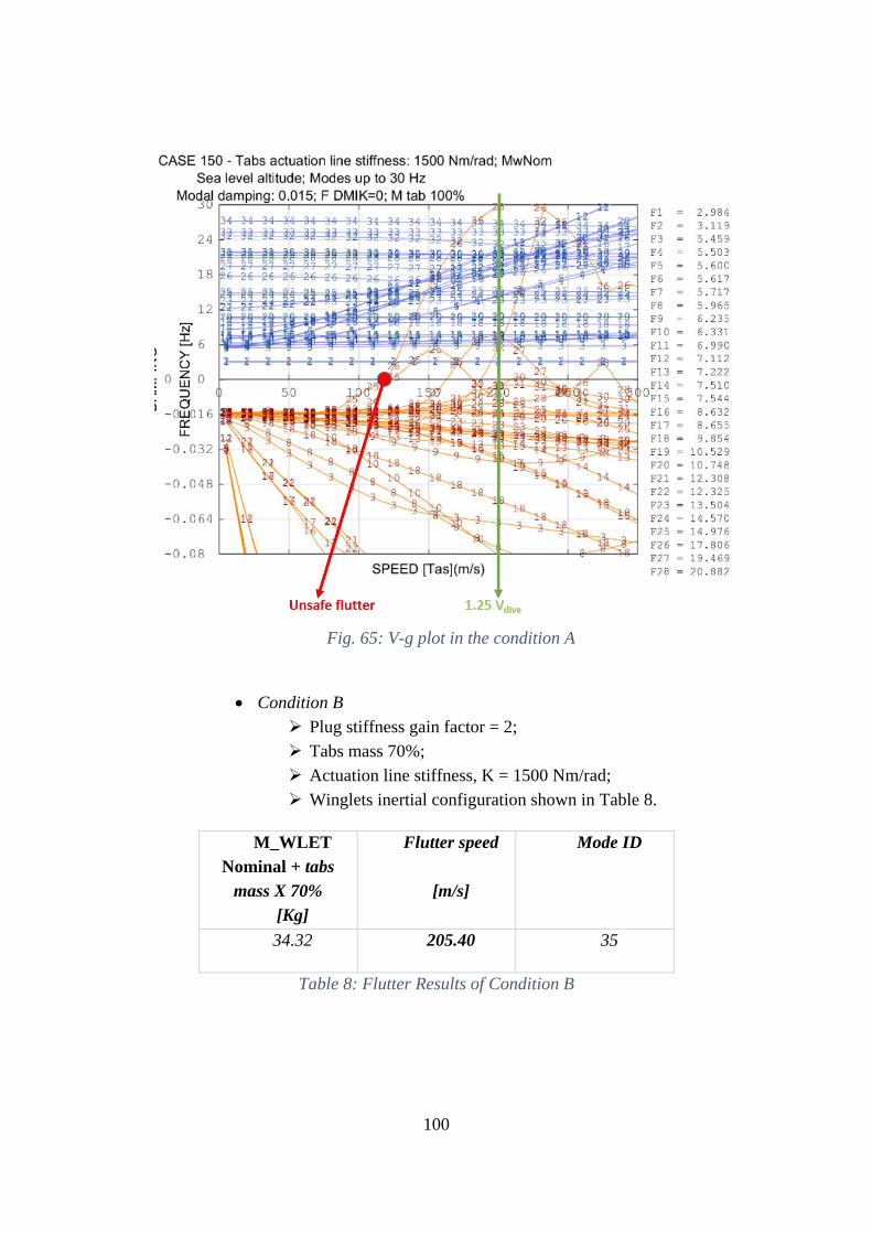
100
Fig. 65: V-g plot in the condition A
• Condition B
➢ Plug stiffness gain factor = 2;
➢ Tabs mass 70%;
➢ Actuation line stiffness, K = 1500 Nm/rad;
➢ Winglets inertial configuration shown in Table 8.
M_WLET
Nominal + tabs
mass X 70%
[Kg]
Flutter speed
[m/s]
Mode ID
34.32 205.40 35
Table 8: Flutter Results of Condition B
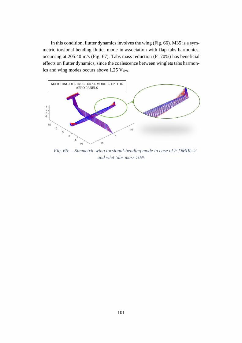
101
In this condition, flutter dynamics involves the wing (Fig. 66). M35 is a sym-
metric torsional-bending flutter mode in association with flap tabs harmonics,
occurring at 205.40 m/s (Fig. 67). Tabs mass reduction (F=70%) has beneficial
effects on flutter dynamics, since the coalescence between winglets tabs harmon-
ics and wing modes occurs above 1.25 Vdive.
Fig. 66: – Simmetric wing torsional-bending mode in case of F DMIK=2
and wlet tabs mass 70%
MATCHING OF STRUCTURAL MODE 35 ON THE
AERO PANELS
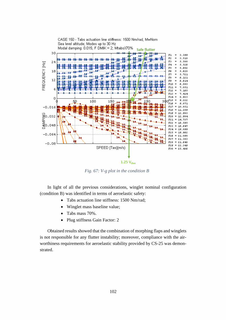
102
Fig. 67: V-g plot in the condition B
In light of all the previous considerations, winglet nominal configuration
(condition B) was identified in terms of aeroelastic safety:
• Tabs actuation line stiffness: 1500 Nm/rad;
• Winglet mass baseline value;
• Tabs mass 70%.
• Plug stiffness Gain Factor: 2
Obtained results showed that the combination of morphing flaps and winglets
is not responsible for any flutter instability; moreover, compliance with the air-
worthiness requirements for aeroelastic stability provided by CS-25 was demon-
strated.
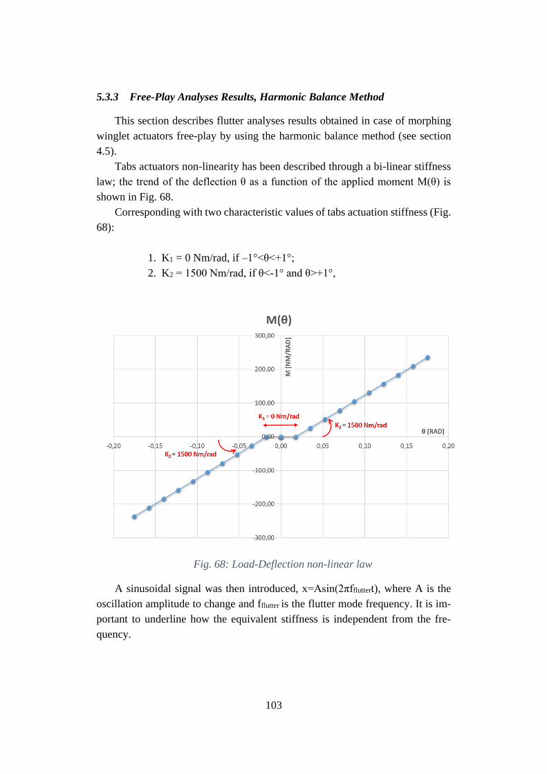
103
5.3.3 Free-Play Analyses Results, Harmonic Balance Method
This section describes flutter analyses results obtained in case of morphing
winglet actuators free-play by using the harmonic balance method (see section
4.5).
Tabs actuators non-linearity has been described through a bi-linear stiffness
law; the trend of the deflection θ as a function of the applied moment M(θ) is
shown in Fig. 68.
Corresponding with two characteristic values of tabs actuation stiffness (Fig.
68):
1. K1 = 0 Nm/rad, if –1°<θ<+1°;
2. K2 = 1500 Nm/rad, if θ<-1° and θ>+1°,
Fig. 68: Load-Deflection non-linear law
A sinusoidal signal was then introduced, x=Asin(2πffluttert), where A is the
oscillation amplitude to change and fflutter is the flutter mode frequency. It is im-
portant to underline how the equivalent stiffness is independent from the fre-
quency.
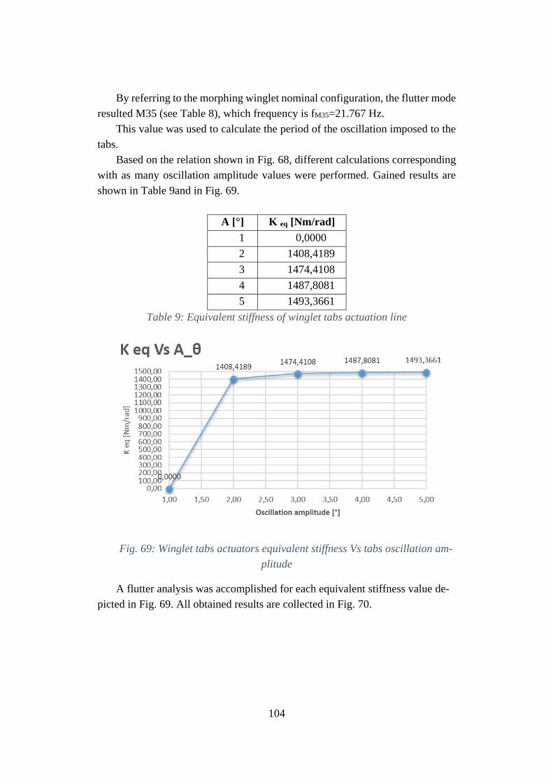
104
By referring to the morphing winglet nominal configuration, the flutter mode
resulted M35 (see Table 8), which frequency is fM35=21.767 Hz.
This value was used to calculate the period of the oscillation imposed to the
tabs.
Based on the relation shown in Fig. 68, different calculations corresponding
with as many oscillation amplitude values were performed. Gained results are
shown in Table 9and in Fig. 69.
A [°] K eq [Nm/rad]
1 0,0000
2 1408,4189
3 1474,4108
4 1487,8081
5 1493,3661
Table 9: Equivalent stiffness of winglet tabs actuation line
Fig. 69: Winglet tabs actuators equivalent stiffness Vs tabs oscillation am-
plitude
A flutter analysis was accomplished for each equivalent stiffness value de-
picted in Fig. 69. All obtained results are collected in Fig. 70.
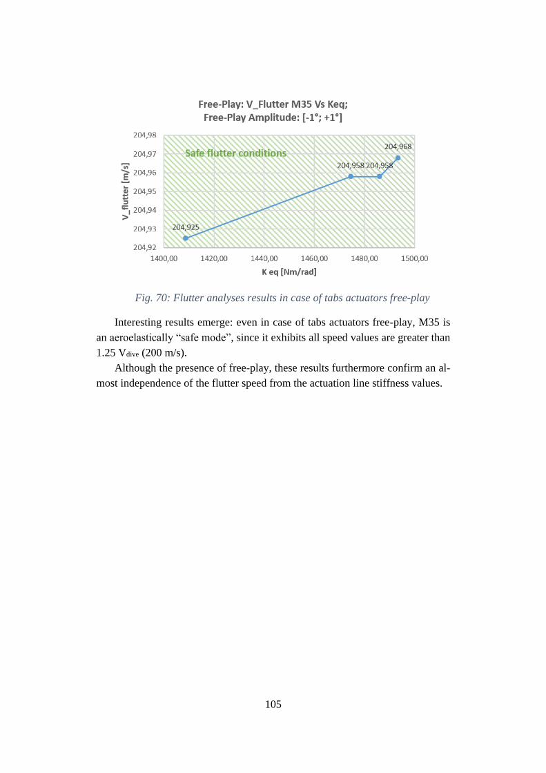
105
Fig. 70: Flutter analyses results in case of tabs actuators free-play
Interesting results emerge: even in case of tabs actuators free-play, M35 is
an aeroelastically “safe mode”, since it exhibits all speed values are greater than
1.25 Vdive (200 m/s).
Although the presence of free-play, these results furthermore confirm an al-
most independence of the flutter speed from the actuation line stiffness values.
106
6 Morphing Wing – Safety and Reliability issues
6.1 Introduction
A functional analysis is a prerequisite to address safety and certification as-
pects of aircraft equipped with morphing systems. In particular, it is fundamental
to identify firstly the aircraft functions which can be enhanced by the use of such
devices and the corresponding aircraft flight segments. After that, all the potential
failures of the morphing kinematics shall be evaluated by demonstrating that they
do not compromise any aircraft general function and capability.
Despite the growing advances in morphing wing technologies, morphing de-
vices continue to be perceived as highly difficult to certify by the aviation indus-
try. Due to the augmented DOF, morphing wings are highly prone to aeroelastic
instabilities with respect to conventional wing architectures. However, beyond
structural or any other consideration of airworthiness nature, the novel aircraft
functions enabled by morphing systems imposes a thorough examination of the
associated risks which may impact on aircraft flight capabilities and crew work-
load. However, as investigated in this work, for systems related to structural load
alleviation and control functions, the safety classification and relevant safety fig-
ures shall also be managed as a structural design driver. This is because a safety
factor (SF) is recommended for those failures whose probability of occurrence is
higher than 10-5 per flight hour.
The safety properties of morphing devices are established primarily by anal-
ysis. The potential failures of electromechanically actuated morphing devices, for
instance, may range from jamming to loss of power supplies and control lanes,
thus resulting in specific technical requirements that can be traced to the top-level
aircraft functions. An example of a fault tree of an electromechanical actuator is
given in Fig. 71. The extensive use of EMA actuation in the most advanced ex-
amples of morphing devices confirms the sensitivity of this issue given the safety
impact of morphing wing devices on aircraft operation.
This chapter provides general guidelines for safety-driven design of morph-
ing devices. The study begins with a qualitative analysis of the morphing wing
functions at subsystem level to identify potential design faults, maintenance and
crew workload impact, as well as external environment risks. The severity of the
hazards are determined and ranked in specific classes, indicative of the maximum
tolerable probability of occurrence for a specific event, resulting in safety design
objectives. A list of morphing system-level functional and safety objectives is
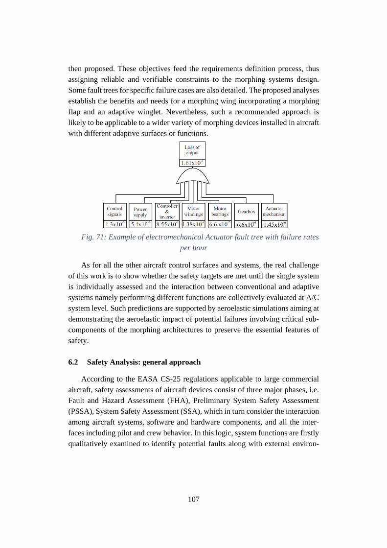
107
then proposed. These objectives feed the requirements definition process, thus
assigning reliable and verifiable constraints to the morphing systems design.
Some fault trees for specific failure cases are also detailed. The proposed analyses
establish the benefits and needs for a morphing wing incorporating a morphing
flap and an adaptive winglet. Nevertheless, such a recommended approach is
likely to be applicable to a wider variety of morphing devices installed in aircraft
with different adaptive surfaces or functions.
Fig. 71: Example of electromechanical Actuator fault tree with failure rates
per hour
As for all the other aircraft control surfaces and systems, the real challenge
of this work is to show whether the safety targets are met until the single system
is individually assessed and the interaction between conventional and adaptive
systems namely performing different functions are collectively evaluated at A/C
system level. Such predictions are supported by aeroelastic simulations aiming at
demonstrating the aeroelastic impact of potential failures involving critical sub-
components of the morphing architectures to preserve the essential features of
safety.
6.2 Safety Analysis: general approach
According to the EASA CS-25 regulations applicable to large commercial
aircraft, safety assessments of aircraft devices consist of three major phases, i.e.
Fault and Hazard Assessment (FHA), Preliminary System Safety Assessment
(PSSA), System Safety Assessment (SSA), which in turn consider the interaction
among aircraft systems, software and hardware components, and all the inter-
faces including pilot and crew behavior. In this logic, system functions are firstly
qualitatively examined to identify potential faults along with external environ-
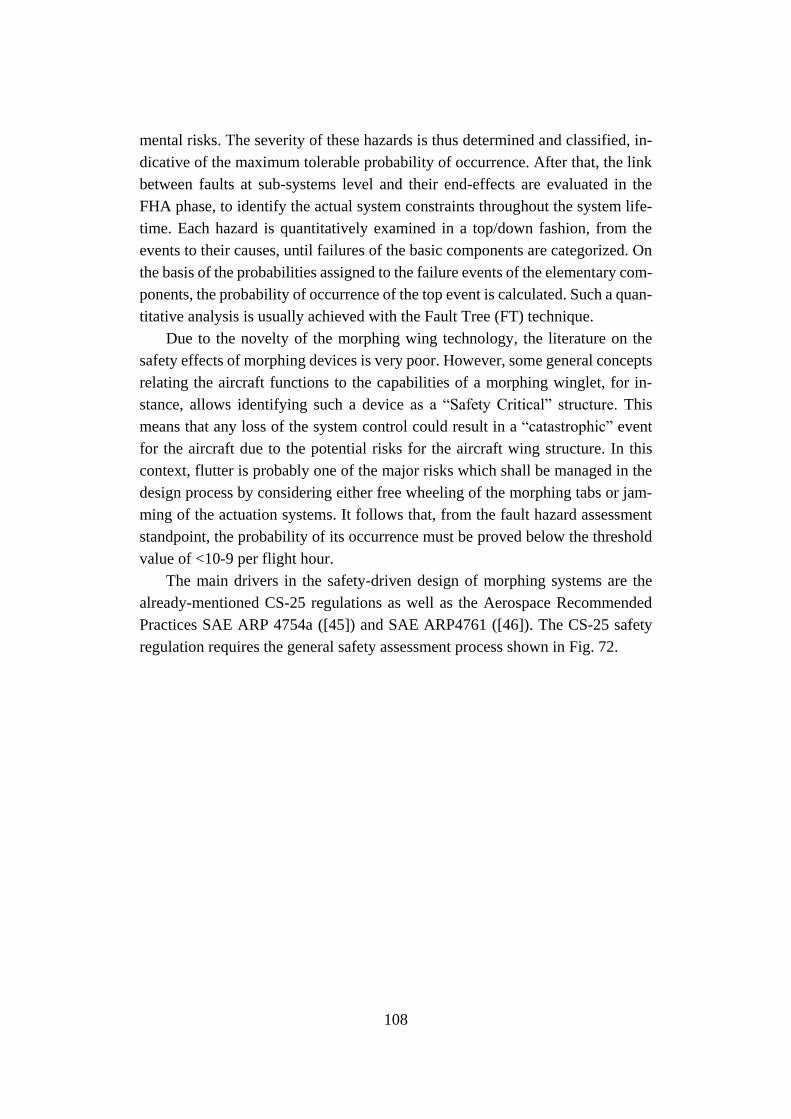
108
mental risks. The severity of these hazards is thus determined and classified, in-
dicative of the maximum tolerable probability of occurrence. After that, the link
between faults at sub-systems level and their end-effects are evaluated in the
FHA phase, to identify the actual system constraints throughout the system life-
time. Each hazard is quantitatively examined in a top/down fashion, from the
events to their causes, until failures of the basic components are categorized. On
the basis of the probabilities assigned to the failure events of the elementary com-
ponents, the probability of occurrence of the top event is calculated. Such a quan-
titative analysis is usually achieved with the Fault Tree (FT) technique.
Due to the novelty of the morphing wing technology, the literature on the
safety effects of morphing devices is very poor. However, some general concepts
relating the aircraft functions to the capabilities of a morphing winglet, for in-
stance, allows identifying such a device as a “Safety Critical” structure. This
means that any loss of the system control could result in a “catastrophic” event
for the aircraft due to the potential risks for the aircraft wing structure. In this
context, flutter is probably one of the major risks which shall be managed in the
design process by considering either free wheeling of the morphing tabs or jam-
ming of the actuation systems. It follows that, from the fault hazard assessment
standpoint, the probability of its occurrence must be proved below the threshold
value of <10-9 per flight hour.
The main drivers in the safety-driven design of morphing systems are the
already-mentioned CS-25 regulations as well as the Aerospace Recommended
Practices SAE ARP 4754a ([45]) and SAE ARP4761 ([46]). The CS-25 safety
regulation requires the general safety assessment process shown in Fig. 72.
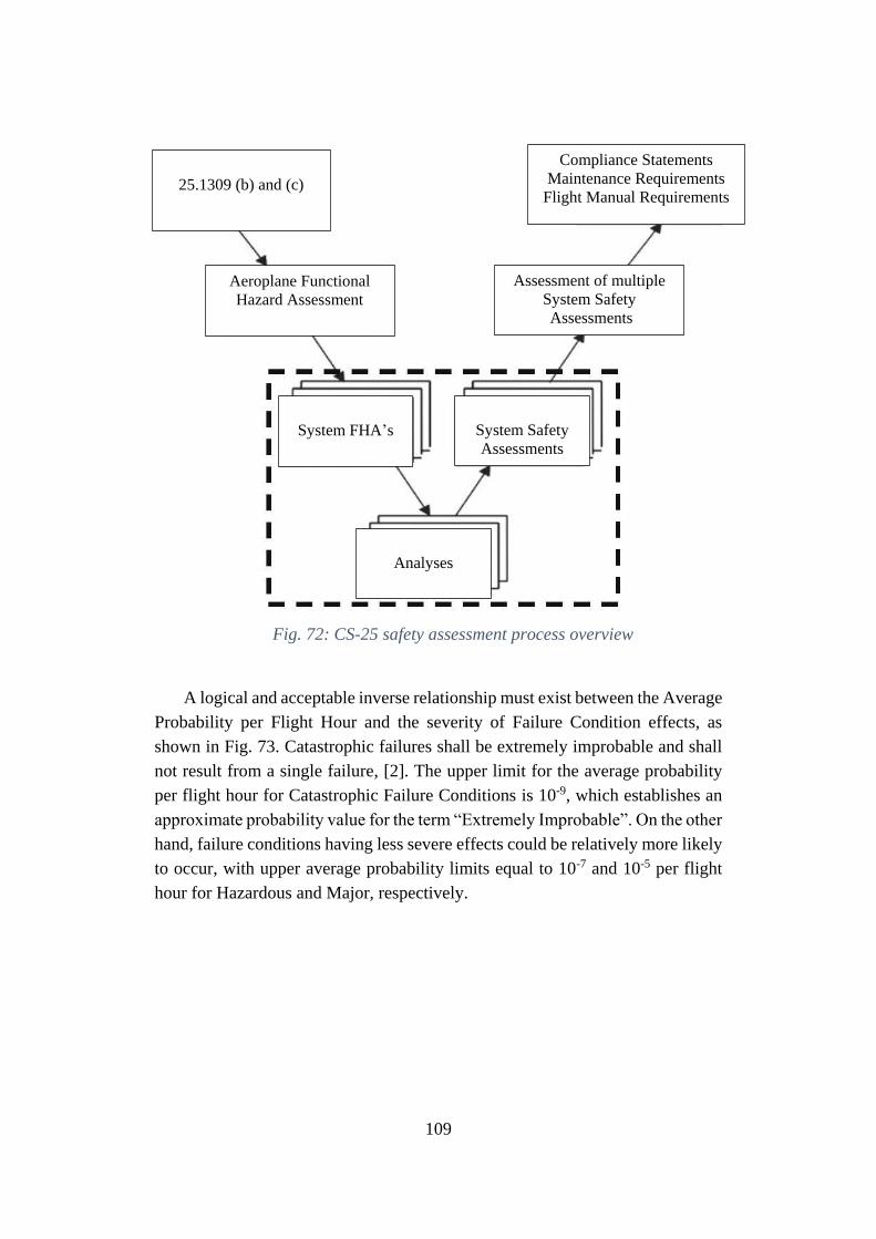
109
Fig. 72: CS-25 safety assessment process overview
A logical and acceptable inverse relationship must exist between the Average
Probability per Flight Hour and the severity of Failure Condition effects, as
shown in Fig. 73. Catastrophic failures shall be extremely improbable and shall
not result from a single failure, [2]. The upper limit for the average probability
per flight hour for Catastrophic Failure Conditions is 10-9, which establishes an
approximate probability value for the term “Extremely Improbable”. On the other
hand, failure conditions having less severe effects could be relatively more likely
to occur, with upper average probability limits equal to 10-7 and 10-5 per flight
hour for Hazardous and Major, respectively.
25.1309 (b) and (c)
Aeroplane Functional
Hazard Assessment
Compliance Statements
Maintenance Requirements
Flight Manual Requirements
Assessment of multiple
System Safety
Assessments
System FHA’s
System Safety
Assessments
Analyses
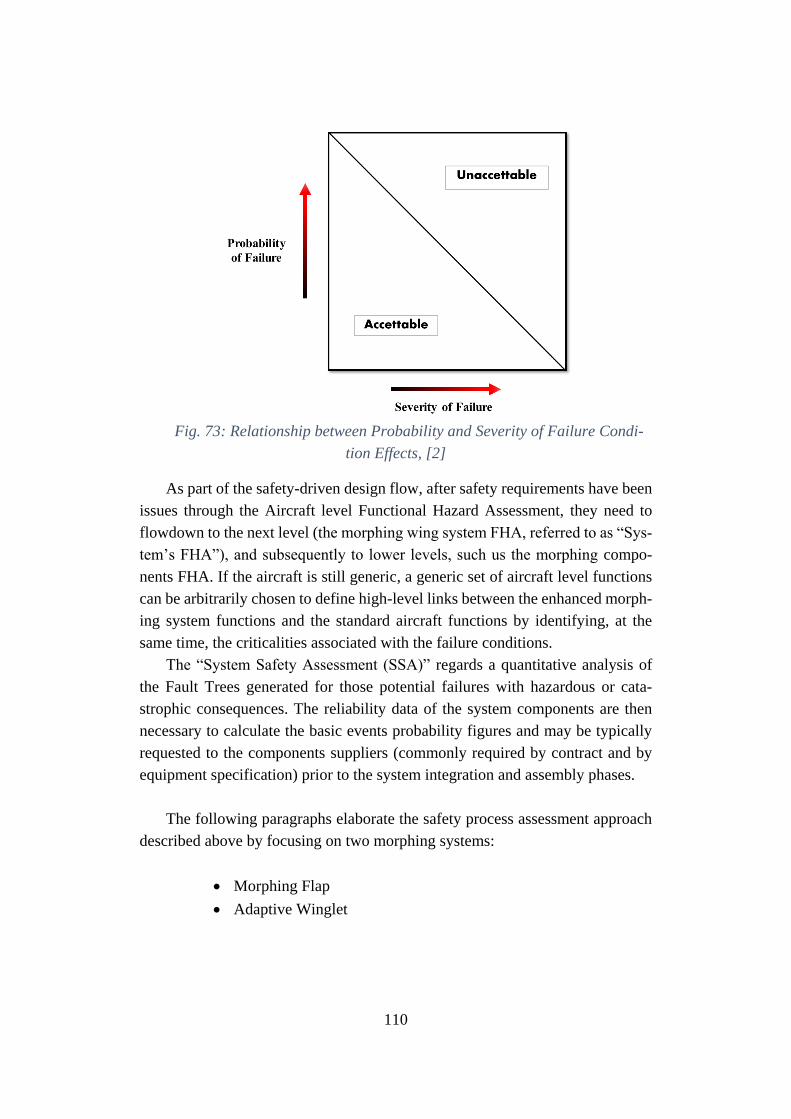
110
Fig. 73: Relationship between Probability and Severity of Failure Condi-
tion Effects, [2]
As part of the safety-driven design flow, after safety requirements have been
issues through the Aircraft level Functional Hazard Assessment, they need to
flowdown to the next level (the morphing wing system FHA, referred to as “Sys-
tem’s FHA”), and subsequently to lower levels, such us the morphing compo-
nents FHA. If the aircraft is still generic, a generic set of aircraft level functions
can be arbitrarily chosen to define high-level links between the enhanced morph-
ing system functions and the standard aircraft functions by identifying, at the
same time, the criticalities associated with the failure conditions.
The “System Safety Assessment (SSA)” regards a quantitative analysis of
the Fault Trees generated for those potential failures with hazardous or cata-
strophic consequences. The reliability data of the system components are then
necessary to calculate the basic events probability figures and may be typically
requested to the components suppliers (commonly required by contract and by
equipment specification) prior to the system integration and assembly phases.
The following paragraphs elaborate the safety process assessment approach
described above by focusing on two morphing systems:
• Morphing Flap
• Adaptive Winglet
111
6.2.1 Functional Hazard Assessment - FHA
Functional hazard assessment is a safety analysis at system/aircraft func-
tional level. As reported on the already-mentioned SAE ARP 4754a [45], the
FHA “examines aircraft and system functions to identify potential functional fail-
ures and classifies the hazards associated with specific Failure Conditions. The
FHA is developed early in the development process and is updated as new func-
tions or Failure Conditions are identified. Thus, the FHA is a living document
throughout the design development cycle”. The functional failures are thus iden-
tified with the associated severity. Then, qualitative requirements are set in this
analysis (redundancy, Functional Design Assurance Level (FDAL), specific
monitoring, etc.).
When dealing with a morphing device, the following failure scenarios are
very likely to occur:
• Total loss of function,
• Partial loss of function,
• Erroneous provision of function, and
• Inadvertent provision of function
Within the total loss of function, we may include very dangerous conditions
such as uncommanded/undamped free floating of the moveable surface or de-
tected/undetected runaway of the morphing surface involving mainly the actua-
tors.
The hazards associated with specific failure conditions are classified accord-
ing to the safety effect, as follows [45]:
NO SAFETY EFFECT (NSE) “Failure Conditions that would have no effect
on safety; for example, Failure Conditions that would not affect the operational
capability of the aeroplane or increase crew workload”.
MINOR (MIN) “Failure Conditions which would not significantly reduce
aeroplane safety, and which involve crew actions that are well within their capa-
bilities. Minor Failure Conditions may include, for example, a slight reduction in
safety margins or functional capabilities, a slight increase in crew workload, such
as routine flight plan changes, or some physical discomfort to passengers or cabin
crew”.
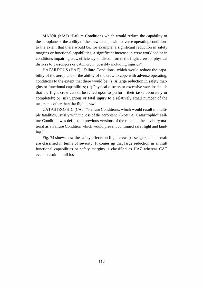
112
MAJOR (MAJ) “Failure Conditions which would reduce the capability of
the aeroplane or the ability of the crew to cope with adverse operating conditions
to the extent that there would be, for example, a significant reduction in safety
margins or functional capabilities, a significant increase in crew workload or in
conditions impairing crew efficiency, or discomfort to the flight crew, or physical
distress to passengers or cabin crew, possibly including injuries”.
HAZARDOUS (HAZ) “Failure Conditions, which would reduce the capa-
bility of the aeroplane or the ability of the crew to cope with adverse operating,
conditions to the extent that there would be: (i) A large reduction in safety mar-
gins or functional capabilities; (ii) Physical distress or excessive workload such
that the flight crew cannot be relied upon to perform their tasks accurately or
completely; or (iii) Serious or fatal injury to a relatively small number of the
occupants other than the flight crew”.
CATASTROPHIC (CAT) “Failure Conditions, which would result in multi-
ple fatalities, usually with the loss of the aeroplane. (Note: A “Catastrophic” Fail-
ure Condition was defined in previous versions of the rule and the advisory ma-
terial as a Failure Condition which would prevent continued safe flight and land-
ing.)”.
Fig. 74 shows how the safety effects on flight crew, passengers, and aircraft
are classified in terms of severity. It comes up that large reduction in aircraft
functional capabilities or safety margins is classified as HAZ whereas CAT
events result in hull loss.
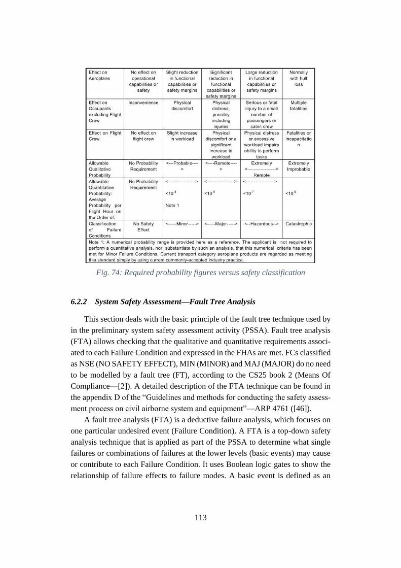
113
Fig. 74: Required probability figures versus safety classification
6.2.2 System Safety Assessment—Fault Tree Analysis
This section deals with the basic principle of the fault tree technique used by
in the preliminary system safety assessment activity (PSSA). Fault tree analysis
(FTA) allows checking that the qualitative and quantitative requirements associ-
ated to each Failure Condition and expressed in the FHAs are met. FCs classified
as NSE (NO SAFETY EFFECT), MIN (MINOR) and MAJ (MAJOR) do no need
to be modelled by a fault tree (FT), according to the CS25 book 2 (Means Of
Compliance—[2]). A detailed description of the FTA technique can be found in
the appendix D of the “Guidelines and methods for conducting the safety assess-
ment process on civil airborne system and equipment”—ARP 4761 ([46]).
A fault tree analysis (FTA) is a deductive failure analysis, which focuses on
one particular undesired event (Failure Condition). A FTA is a top-down safety
analysis technique that is applied as part of the PSSA to determine what single
failures or combinations of failures at the lower levels (basic events) may cause
or contribute to each Failure Condition. It uses Boolean logic gates to show the
relationship of failure effects to failure modes. A basic event is defined as an
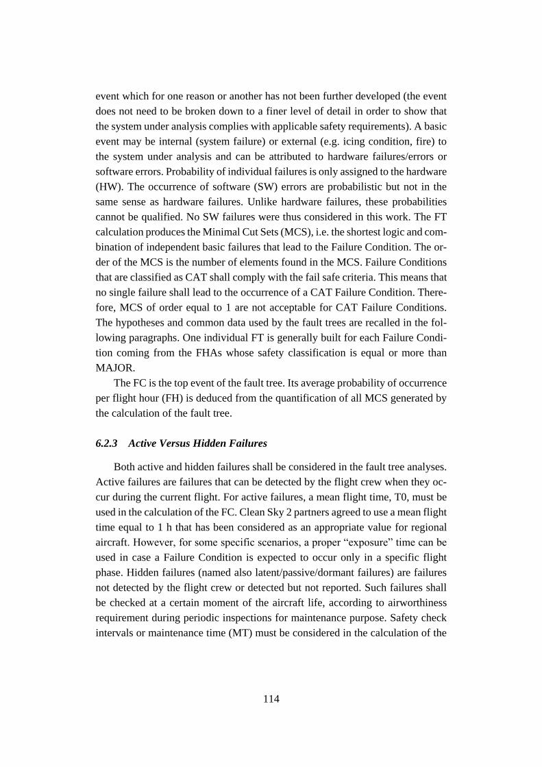
114
event which for one reason or another has not been further developed (the event
does not need to be broken down to a finer level of detail in order to show that
the system under analysis complies with applicable safety requirements). A basic
event may be internal (system failure) or external (e.g. icing condition, fire) to
the system under analysis and can be attributed to hardware failures/errors or
software errors. Probability of individual failures is only assigned to the hardware
(HW). The occurrence of software (SW) errors are probabilistic but not in the
same sense as hardware failures. Unlike hardware failures, these probabilities
cannot be qualified. No SW failures were thus considered in this work. The FT
calculation produces the Minimal Cut Sets (MCS), i.e. the shortest logic and com-
bination of independent basic failures that lead to the Failure Condition. The or-
der of the MCS is the number of elements found in the MCS. Failure Conditions
that are classified as CAT shall comply with the fail safe criteria. This means that
no single failure shall lead to the occurrence of a CAT Failure Condition. There-
fore, MCS of order equal to 1 are not acceptable for CAT Failure Conditions.
The hypotheses and common data used by the fault trees are recalled in the fol-
lowing paragraphs. One individual FT is generally built for each Failure Condi-
tion coming from the FHAs whose safety classification is equal or more than
MAJOR.
The FC is the top event of the fault tree. Its average probability of occurrence
per flight hour (FH) is deduced from the quantification of all MCS generated by
the calculation of the fault tree.
6.2.3 Active Versus Hidden Failures
Both active and hidden failures shall be considered in the fault tree analyses.
Active failures are failures that can be detected by the flight crew when they oc-
cur during the current flight. For active failures, a mean flight time, T0, must be
used in the calculation of the FC. Clean Sky 2 partners agreed to use a mean flight
time equal to 1 h that has been considered as an appropriate value for regional
aircraft. However, for some specific scenarios, a proper “exposure” time can be
used in case a Failure Condition is expected to occur only in a specific flight
phase. Hidden failures (named also latent/passive/dormant failures) are failures
not detected by the flight crew or detected but not reported. Such failures shall
be checked at a certain moment of the aircraft life, according to airworthiness
requirement during periodic inspections for maintenance purpose. Safety check
intervals or maintenance time (MT) must be considered in the calculation of the

115
FC involving hidden failures. The MT value is set based on the usual checks
(periodic inspections) of the aircraft. The standard safety check intervals (A
checks, B checks …) have been considered in the quantification of the FTs. An
interval of 8000 flight hours was considered between maintenance checks, i.e.
disassembly and inspection of all hinges for detection and elimination of all
dormant failures. For equipment that is never inspected, we use the aircraft life-
time. This value comes from “Fatigue Loads design criteria”. MT of “60,000 h”
was set as a standard value but a calculation with a more conservative value of
87,600 h was considered, as reported in [47].
6.2.4 On safety factor
The structural damage tolerance and loads are out of the PSSA scope. Struc-
ture specialists in separated documents address such specific safety issues. How-
ever what is requested is to identify the systems that may exert loads on structural
parts when failures occur as explained in the CS25.303 section “Factor of safety”
[2]: “…Unless otherwise specified, a factor of safety of 1.5 must be applied to
the prescribed limit load which are considered external loads on the structure”
(Fig. 75).
Fig. 75: Safety factor vs probability in failure condition
6.3 Morphing devices: Aircraft level functions
An assessment of the generic A/C level functions is proposed in [45]. The
functions which may be namely improved by integrating morphing control sur-
faces, like morphing flap and adaptive winglet, into an aircraft wing are listed in
Table 10. In particular, the use of these devices namely impacts on the following
A/C level functions:
• Drag reduction
116
• Lift adaptation
• Gust/Load alleviation
• Vibration and Fatigue control
AIRCRAFT FUNCTIONS
2. Plan, Generate and Control A/C movement
2.2 Generate and Control aircraft movement
2.2.5 Control A/C Aerodynamics Configuration
2.2.5.1 Control Lift and Drag
2.2.6 Protect Aerodynamic Control
2.2.6.1 To provide protection against turbulence effects
2.2.6.2 To provide protection against stall load
2.2.7 Provide aerodynamic control forces
2.2.8 Support Supplemental flight control
2.2.8.1 To provide overload protection and A/C load protection
2.2.8.2 To provide protection against manoeuvres effects
2.2.13 Generate lift
2.2.14 Provide aerodynamic stability
8. Provide containment and internal support
8.1 Provide containment
8.1.2 Provide structural integrity and loads distribution
8.1.2.1 To provide fatigue protection
Table 10: Aircraft functions impacted by Morphing Wing concept, [45]-
[46]
A very high level description of the morphing device is generally required to
understand the above reported functional breakdown. Overall, these systems aim
at reducing wing drag, at controlling wing lift distribution and at reducing wing
loads (including vibrations and fatigue loads). In addition, the wing structural
integrity can be also taken into account due to the structural load alleviation /
protection / control function, as envisaged in A/C function 8 “Provide contain-
ment and internal support”.
117
6.4 Morphing flap
The morphing flap is a high lift device capable to generate extra lift during
take-off and landing. Additionally, it is conceived to drastically enhance aircraft
aerodynamic performance in high-lift conditions also through the mode 2 and
mode 3. Less drag directly reduces fuel consumption. However, in case of system
deployment in high speed conditions for drag minimization or lift adaptation, any
possible detachment of the device or erroneous deployment may impact on air-
craft safety. More complex functions such as maneuver load alleviation or gust
load alleviation shall be excluded for morphing flap due to the current technolog-
ical limits. The FHA of the morphing flap is shown in Table 11.
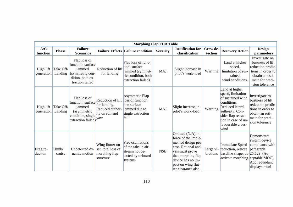
118
Morphing Flap FHA Table
A/C
function Phase
Failure
Scenarios Failure Effects Failure condition Severity
Justification for
classification
Crew de-
tection Recovery Action
Design
parameters
High lift
generation
Take Off/
Landing
Flap loss of
function: surface
jammed
(symmetric con-
dition, both ex-
traction failed
Reduction of lift
for landing
Flap loss of func-
tion: surface
jammed (symmet-
ric condition, both
extraction failed)
MAJ Slight increase in
pilot’s work-load Warning
Land at higher
speed,
limitation of sus-
tained
wind conditions.
Investigate ro-
bustness of lift
reduction predic-
tions in order to
obtain an esti-
mate for preci-
sion tolerance
High lift
generation
Take Off/
Landing
Flap loss of
function: surface
jammed
(asymmetric
condition, single
extraction failed)
Reduction of lift
for landing.
Reduced author-
ity on roll and
yaw
Asymmetic Flap
loss of function:
one surface
jammed due to
single extraction
fail
MAJ Slight increase in
pilot’s work-load Warning
Land at higher
speed, limitation
of sustained wind
conditions.
Reduced lateral
authority. Con-
sider flap retrac-
tion in case of un-
favourable cross-
wind
Investigate ro-
bustness of lift
reduction predic-
tions in order to
obtain an esti-
mate for preci-
sion tolerance
Drag re-
duction
Climb/
cruise
Undetected dy-
namic motion
Wing flutter on-
set, total loss of
morphing flap
structure
Free oscillations
of the tabs in air-
stream not de-
tected by onboard
systems
NSE
Omitted (N/A) in
force of the imple-
mented design pro-
cess. Rational anal-
ysis must prove
that morphing flap
device has no im-
pact on wing flut-
ter clearance also
Large vi-
brations
Immediate Speed
reduction, restore
baseline shape, de-
activate morphing.
Demonstrate
system device
compliance with
paragraph
25.629 (Ac-
ceptable MOC).
Add redundant
displays moni-
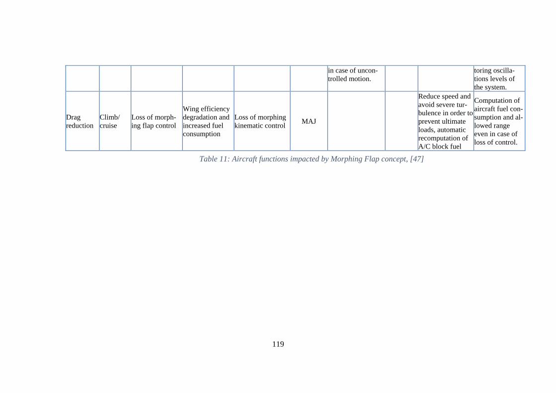
119
in case of uncon-
trolled motion.
toring oscilla-
tions levels of
the system.
Drag
reduction
Climb/
cruise
Loss of morph-
ing flap control
Wing efficiency
degradation and
increased fuel
consumption
Loss of morphing
kinematic control MAJ
Reduce speed and
avoid severe tur-
bulence in order to
prevent ultimate
loads, automatic
recomputation of
A/C block fuel
Computation of
aircraft fuel con-
sumption and al-
lowed range
even in case of
loss of control.
Table 11: Aircraft functions impacted by Morphing Flap concept, [47]
120
On the basis of the probabilities assigned to the failure events of the basic com-
ponents, the probability of occurrence of such top evens shall be then calculated
through the Fault Tree (FT) technique.
Based on what described in the previous sections regarding the morphing flap
architecture and all considerations about the FHA, two different failure scenarios
have been considered in the fault tree analysis concerning the morphing flap:
➢ 1st failure scenario, involving high lift generation function (morph-
ing mode 1);
➢ 2nd failure scenario, involving undetected inadvertent morphing flap
tab control at high speed function (morphing mode 2).
High lift generation function was judged compromised in case of the following
dissociated failure (right or left side):
1. Deployment system failure
2. Morphing system failure ;
Undetected inadvertent morphing flap tab control at high-speed function was
assessed mined in case of the following dissociated failure (right or left side):
1. Loss of morphing kinematic control;
2. Control system failure;
3. Power-off brake failure;
4. Inadvertent tab deflection – undetected.
All listed levels were furthermore exploded according with a rational “top-
down” approach (Fig. 76 and Fig. 77). Reliability Workbench – Isograph ® ([48])
was used to perform the fault tree analyses, by extracting the lowest level events
probability from literature, [49].
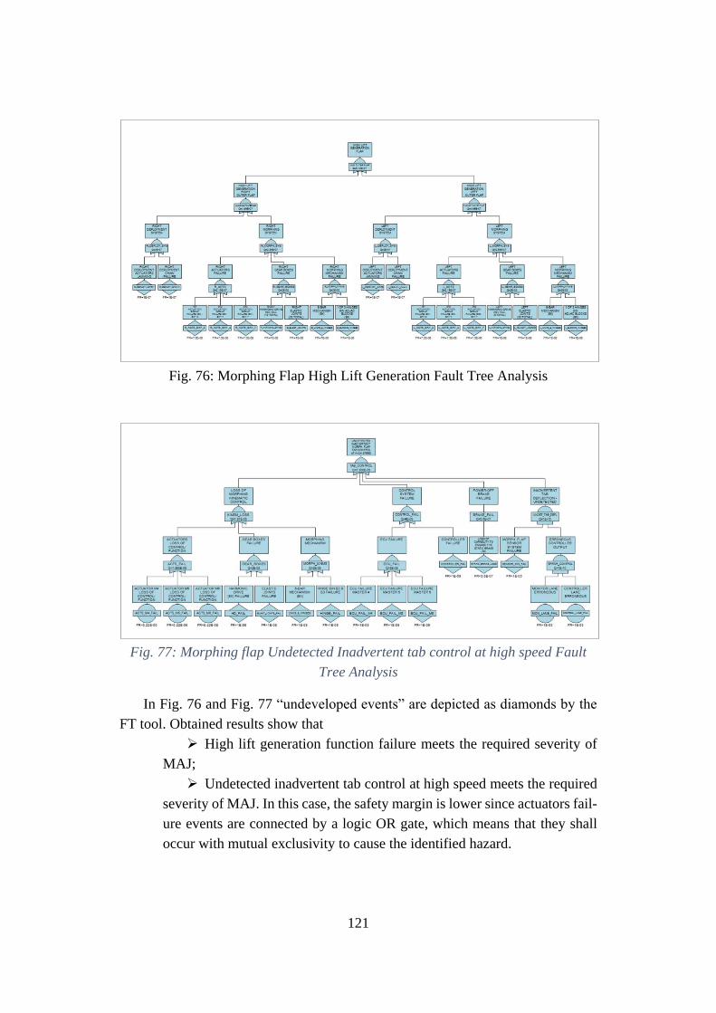
121
Fig. 76: Morphing Flap High Lift Generation Fault Tree Analysis
Fig. 77: Morphing flap Undetected Inadvertent tab control at high speed Fault
Tree Analysis
In Fig. 76 and Fig. 77 “undeveloped events” are depicted as diamonds by the
FT tool. Obtained results show that
➢ High lift generation function failure meets the required severity of
MAJ;
➢ Undetected inadvertent tab control at high speed meets the required
severity of MAJ. In this case, the safety margin is lower since actuators fail-
ure events are connected by a logic OR gate, which means that they shall
occur with mutual exclusivity to cause the identified hazard.
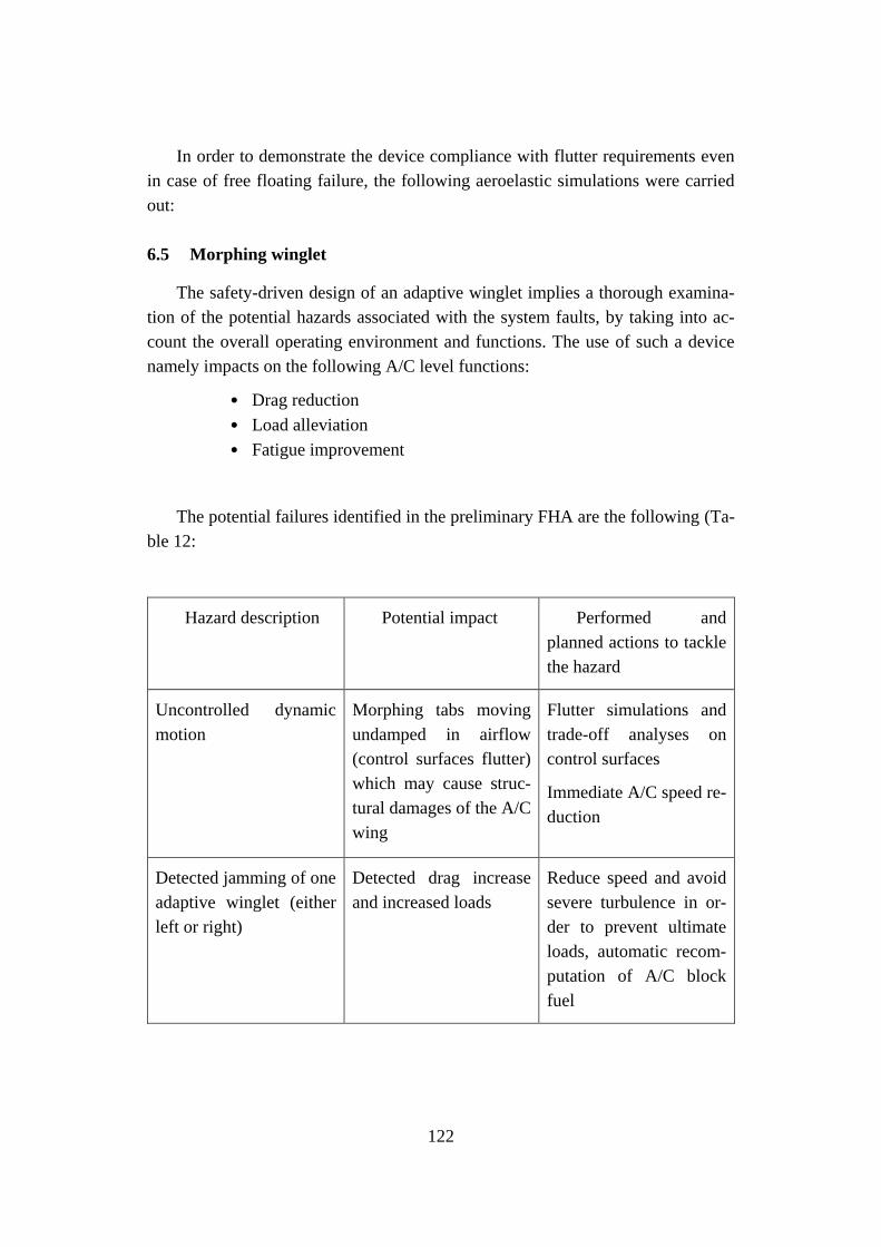
122
In order to demonstrate the device compliance with flutter requirements even
in case of free floating failure, the following aeroelastic simulations were carried
out:
6.5 Morphing winglet
The safety-driven design of an adaptive winglet implies a thorough examina-
tion of the potential hazards associated with the system faults, by taking into ac-
count the overall operating environment and functions. The use of such a device
namely impacts on the following A/C level functions:
• Drag reduction
• Load alleviation
• Fatigue improvement
The potential failures identified in the preliminary FHA are the following (Ta-
ble 12:
Hazard description Potential impact Performed and
planned actions to tackle
the hazard
Uncontrolled dynamic
motion
Morphing tabs moving
undamped in airflow
(control surfaces flutter)
which may cause struc-
tural damages of the A/C
wing
Flutter simulations and
trade-off analyses on
control surfaces
Immediate A/C speed re-
duction
Detected jamming of one
adaptive winglet (either
left or right)
Detected drag increase
and increased loads
Reduce speed and avoid
severe turbulence in or-
der to prevent ultimate
loads, automatic recom-
putation of A/C block
fuel
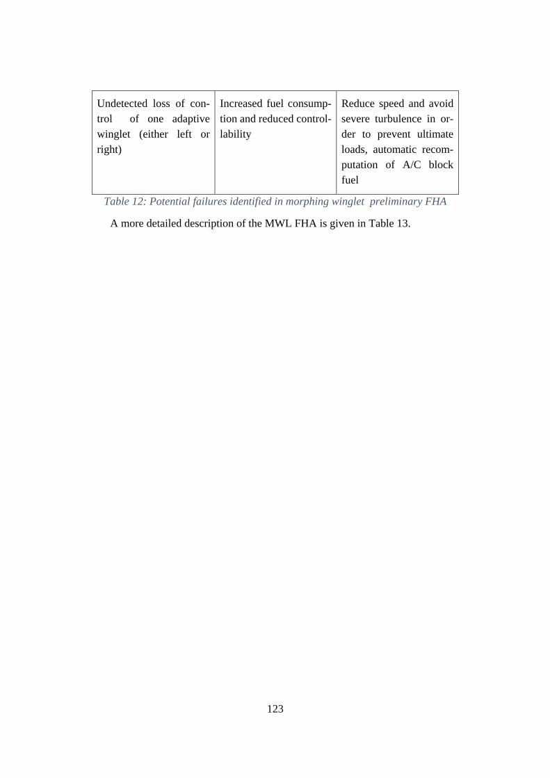
123
Undetected loss of con-
trol of one adaptive
winglet (either left or
right)
Increased fuel consump-
tion and reduced control-
lability
Reduce speed and avoid
severe turbulence in or-
der to prevent ultimate
loads, automatic recom-
putation of A/C block
fuel
Table 12: Potential failures identified in morphing winglet preliminary FHA
A more detailed description of the MWL FHA is given in Table 13.
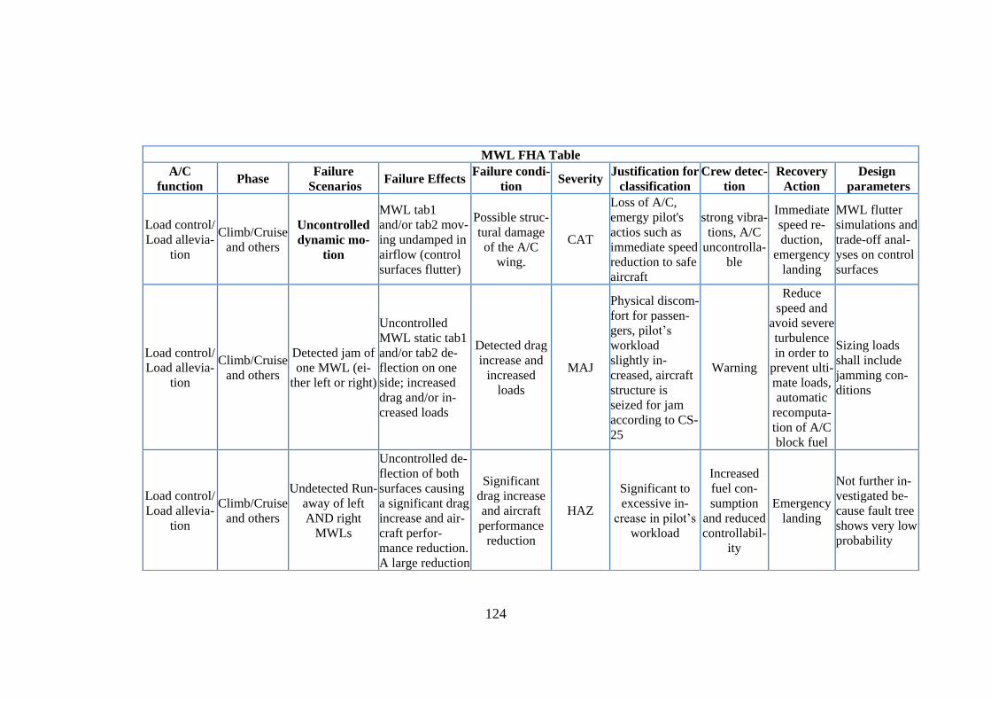
124
MWL FHA Table
A/C
function Phase
Failure
Scenarios Failure Effects
Failure condi-
tion Severity
Justification for
classification
Crew detec-
tion
Recovery
Action
Design
parameters
Load control/
Load allevia-
tion
Climb/Cruise
and others
Uncontrolled
dynamic mo-
tion
MWL tab1
and/or tab2 mov-
ing undamped in
airflow (control
surfaces flutter)
Possible struc-
tural damage
of the A/C
wing.
CAT
Loss of A/C,
emergy pilot's
actios such as
immediate speed
reduction to safe
aircraft
strong vibra-
tions, A/C
uncontrolla-
ble
Immediate
speed re-
duction,
emergency
landing
MWL flutter
simulations and
trade-off anal-
yses on control
surfaces
Load control/
Load allevia-
tion
Climb/Cruise
and others
Detected jam of
one MWL (ei-
ther left or right)
Uncontrolled
MWL static tab1
and/or tab2 de-
flection on one
side; increased
drag and/or in-
creased loads
Detected drag
increase and
increased
loads
MAJ
Physical discom-
fort for passen-
gers, pilot’s
workload
slightly in-
creased, aircraft
structure is
seized for jam
according to CS-
25
Warning
Reduce
speed and
avoid severe
turbulence
in order to
prevent ulti-
mate loads,
automatic
recomputa-
tion of A/C
block fuel
Sizing loads
shall include
jamming con-
ditions
Load control/
Load allevia-
tion
Climb/Cruise
and others
Undetected Run-
away of left
AND right
MWLs
Uncontrolled de-
flection of both
surfaces causing
a significant drag
increase and air-
craft perfor-
mance reduction.
A large reduction
Significant
drag increase
and aircraft
performance
reduction
HAZ
Significant to
excessive in-
crease in pilot’s
workload
Increased
fuel con-
sumption
and reduced
controllabil-
ity
Emergency
landing
Not further in-
vestigated be-
cause fault tree
shows very low
probability
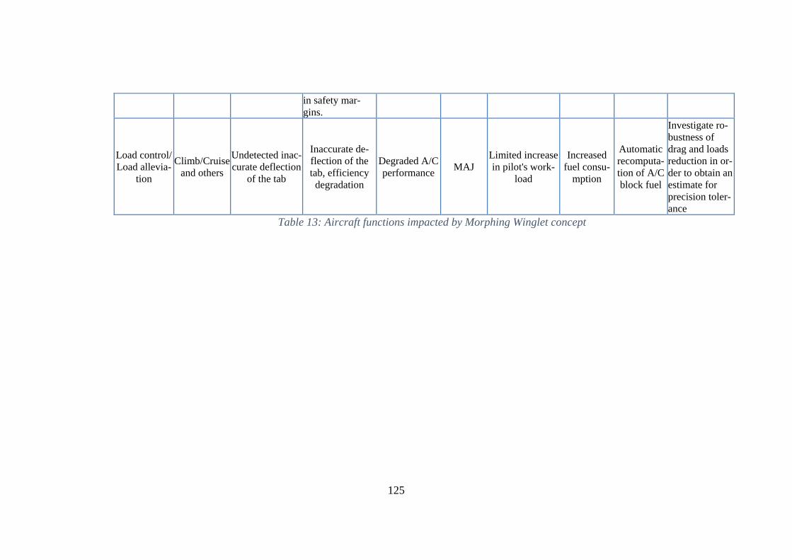
125
in safety mar-
gins.
Load control/
Load allevia-
tion
Climb/Cruise
and others
Undetected inac-
curate deflection
of the tab
Inaccurate de-
flection of the
tab, efficiency
degradation
Degraded A/C
performance MAJ
Limited increase
in pilot's work-
load
Increased
fuel consu-
mption
Automatic
recomputa-
tion of A/C
block fuel
Investigate ro-
bustness of
drag and loads
reduction in or-
der to obtain an
estimate for
precision toler-
ance
Table 13: Aircraft functions impacted by Morphing Winglet concept
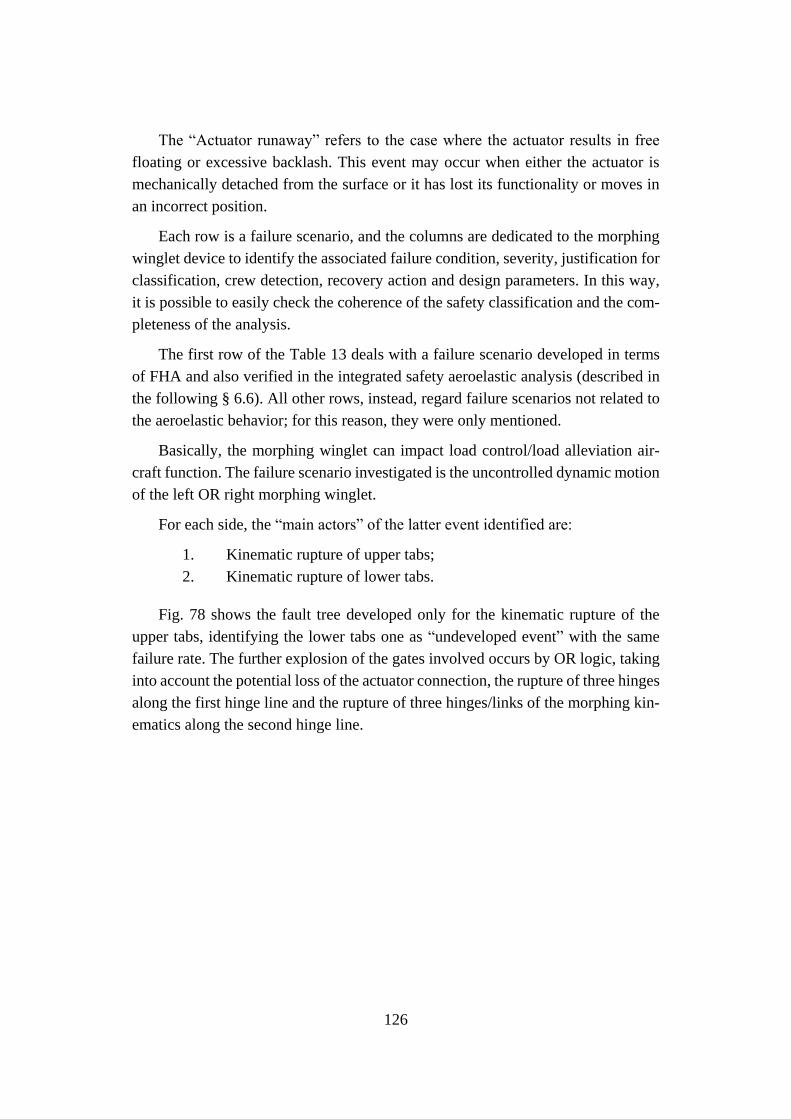
126
The “Actuator runaway” refers to the case where the actuator results in free
floating or excessive backlash. This event may occur when either the actuator is
mechanically detached from the surface or it has lost its functionality or moves in
an incorrect position.
Each row is a failure scenario, and the columns are dedicated to the morphing
winglet device to identify the associated failure condition, severity, justification for
classification, crew detection, recovery action and design parameters. In this way,
it is possible to easily check the coherence of the safety classification and the com-
pleteness of the analysis.
The first row of the Table 13 deals with a failure scenario developed in terms
of FHA and also verified in the integrated safety aeroelastic analysis (described in
the following § 6.6). All other rows, instead, regard failure scenarios not related to
the aeroelastic behavior; for this reason, they were only mentioned.
Basically, the morphing winglet can impact load control/load alleviation air-
craft function. The failure scenario investigated is the uncontrolled dynamic motion
of the left OR right morphing winglet.
For each side, the “main actors” of the latter event identified are:
1. Kinematic rupture of upper tabs;
2. Kinematic rupture of lower tabs.
Fig. 78 shows the fault tree developed only for the kinematic rupture of the
upper tabs, identifying the lower tabs one as “undeveloped event” with the same
failure rate. The further explosion of the gates involved occurs by OR logic, taking
into account the potential loss of the actuator connection, the rupture of three hinges
along the first hinge line and the rupture of three hinges/links of the morphing kin-
ematics along the second hinge line.
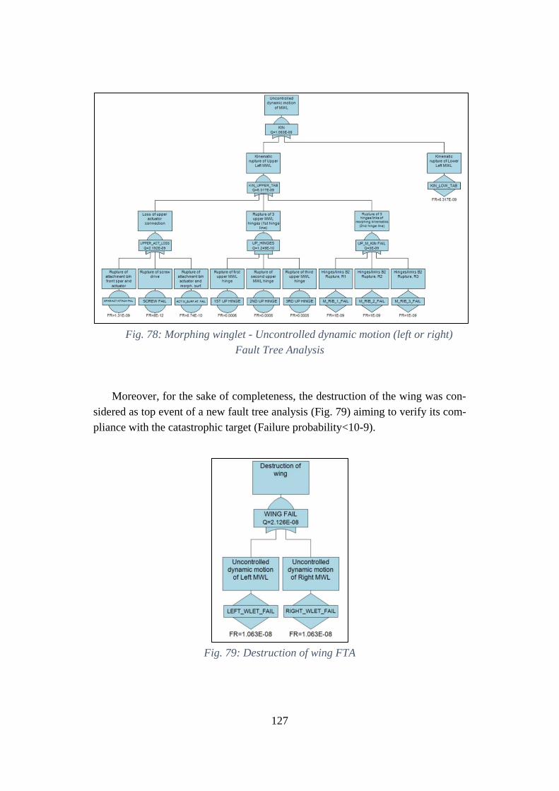
127
Fig. 78: Morphing winglet - Uncontrolled dynamic motion (left or right)
Fault Tree Analysis
Moreover, for the sake of completeness, the destruction of the wing was con-
sidered as top event of a new fault tree analysis (Fig. 79) aiming to verify its com-
pliance with the catastrophic target (Failure probability<10-9).
Fig. 79: Destruction of wing FTA
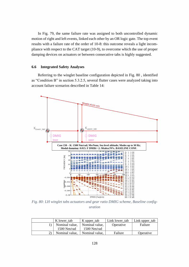
128
In Fig. 79, the same failure rate was assigned to both uncontrolled dynamic
motion of right and left events, linked each other by an OR logic gate. The top event
results with a failure rate of the order of 10-8: this outcome reveals a light incom-
pliance with respect to the CAT target (10-9), to overcome which the use of proper
damping devices on actuators or between consecutive tabs is highly suggested.
6.6 Integrated Safety Analyses
Referring to the winglet baseline configuration depicted in Fig. 80 , identified
as “Condition B” in section 5.3.2.5, several flutter cases were analyzed taking into
account failure scenarios described in Table 14:
Fig. 80: LH winglet tabs actuators and gear ratio DMIG scheme, Baseline config-
uration
K lower_tab K upper_tab Link lower_tab Link upper_tab
1) Nominal value,
1500 Nm/rad
Nominal value,
1500 Nm/rad
Operative Failure
2) Nominal value, Nominal value, Failure Operative
Case 150 – K: 1500 Nm/rad; MwNom; Sea level altitude; Modes up to 30 Hz;
Modal damping: 0.015; F DMIK= 2; Mtabsx70%, BASELINE CONF.
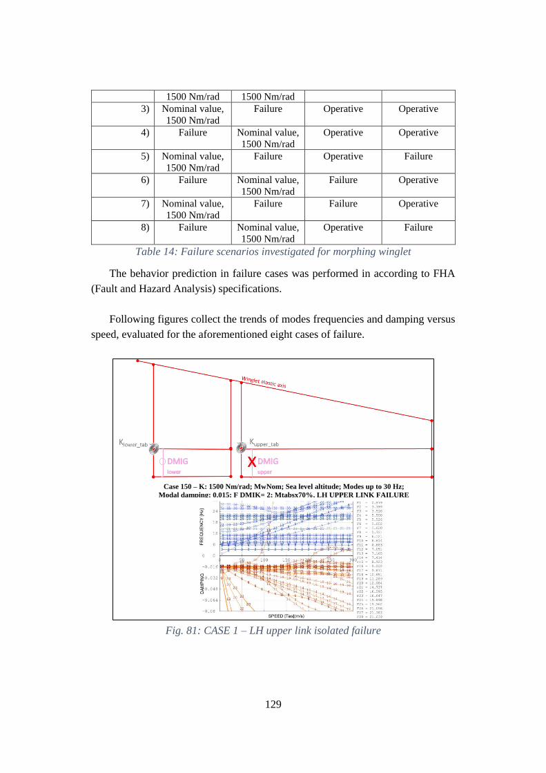
129
1500 Nm/rad 1500 Nm/rad
3) Nominal value,
1500 Nm/rad
Failure Operative Operative
4) Failure Nominal value,
1500 Nm/rad
Operative Operative
5) Nominal value,
1500 Nm/rad
Failure Operative Failure
6) Failure Nominal value,
1500 Nm/rad
Failure Operative
7) Nominal value,
1500 Nm/rad
Failure Failure Operative
8) Failure Nominal value,
1500 Nm/rad
Operative Failure
Table 14: Failure scenarios investigated for morphing winglet
The behavior prediction in failure cases was performed in according to FHA
(Fault and Hazard Analysis) specifications.
Following figures collect the trends of modes frequencies and damping versus
speed, evaluated for the aforementioned eight cases of failure.
Fig. 81: CASE 1 – LH upper link isolated failure
Case 150 – K: 1500 Nm/rad; MwNom; Sea level altitude; Modes up to 30 Hz;
Modal damping: 0.015; F DMIK= 2; Mtabsx70%, LH UPPER LINK FAILURE
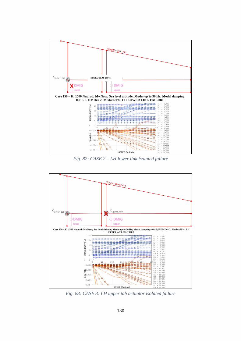
130
Fig. 82: CASE 2 – LH lower link isolated failure
Fig. 83: CASE 3: LH upper tab actuator isolated failure
Case 150 – K: 1500 Nm/rad; MwNom; Sea level altitude; Modes up to 30 Hz; Modal damping:
0.015; F DMIK= 2; Mtabsx70%, LH LOWER LINK FAILURE
SPEED [TAS (m/s)]
Case 150 – K: 1500 Nm/rad; MwNom; Sea level altitude; Modes up to 30 Hz; Modal damping: 0.015; F DMIK= 2; Mtabsx70%, LH
UPPER ACT. FAILURE
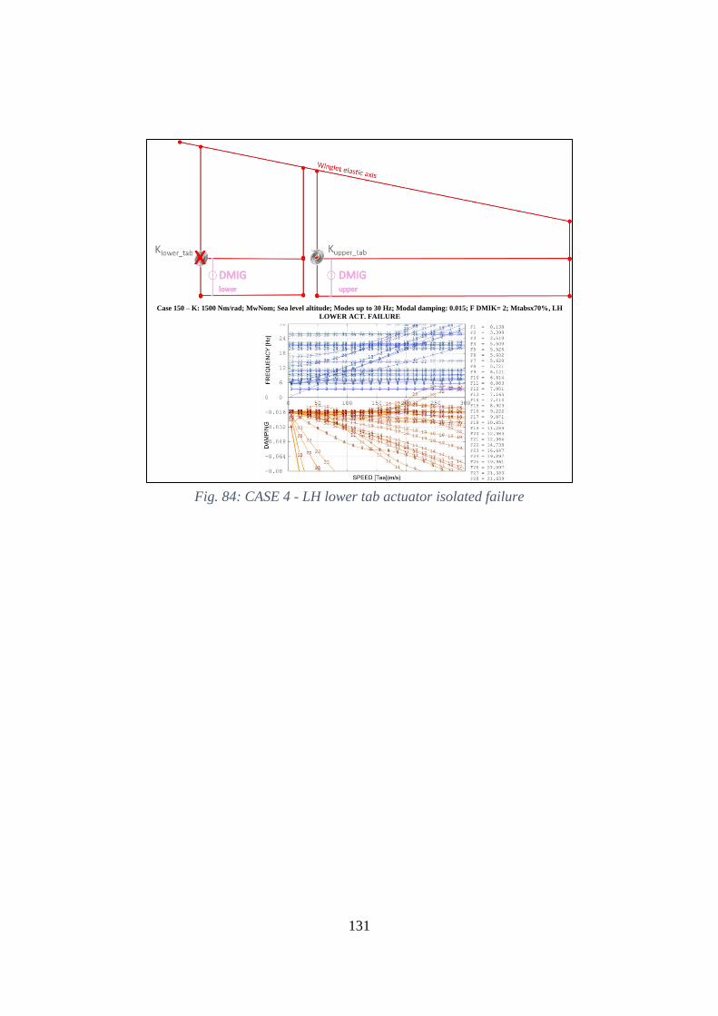
131
Fig. 84: CASE 4 - LH lower tab actuator isolated failure
Case 150 – K: 1500 Nm/rad; MwNom; Sea level altitude; Modes up to 30 Hz; Modal damping: 0.015; F DMIK= 2; Mtabsx70%, LH
LOWER ACT. FAILURE
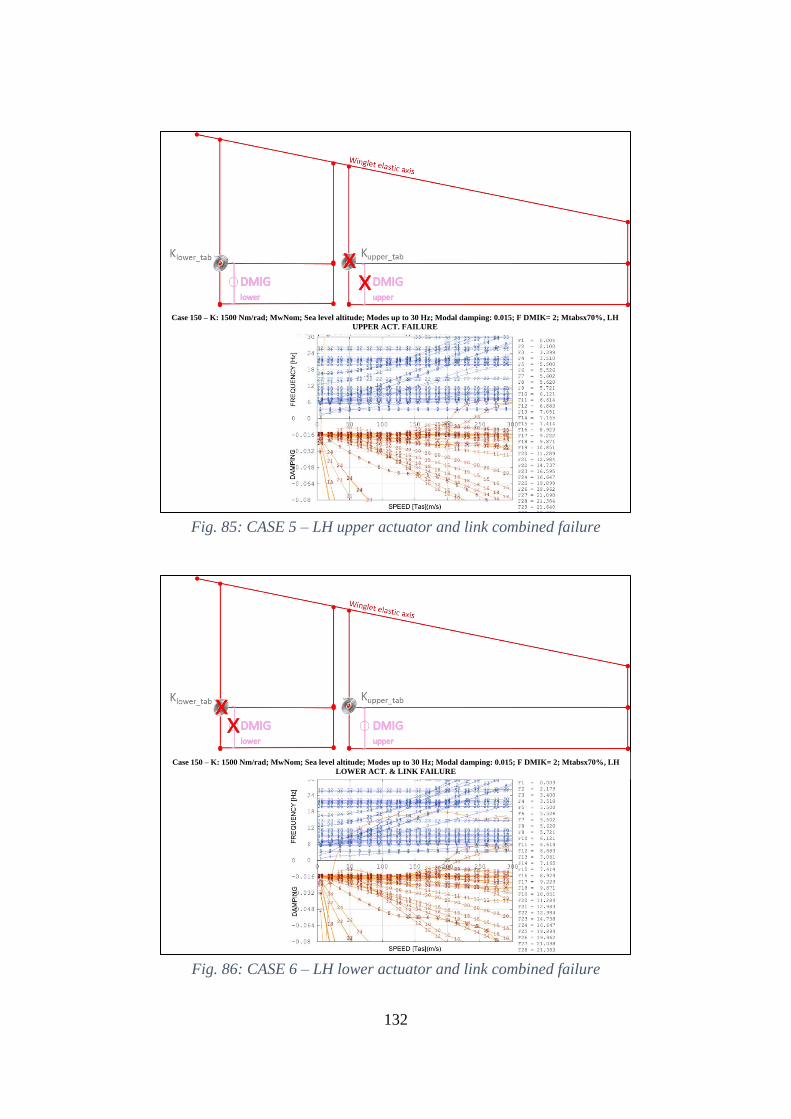
132
Fig. 85: CASE 5 – LH upper actuator and link combined failure
Fig. 86: CASE 6 – LH lower actuator and link combined failure
Case 150 – K: 1500 Nm/rad; MwNom; Sea level altitude; Modes up to 30 Hz; Modal damping: 0.015; F DMIK= 2; Mtabsx70%, LH
UPPER ACT. FAILURE
Case 150 – K: 1500 Nm/rad; MwNom; Sea level altitude; Modes up to 30 Hz; Modal damping: 0.015; F DMIK= 2; Mtabsx70%, LH
LOWER ACT. & LINK FAILURE
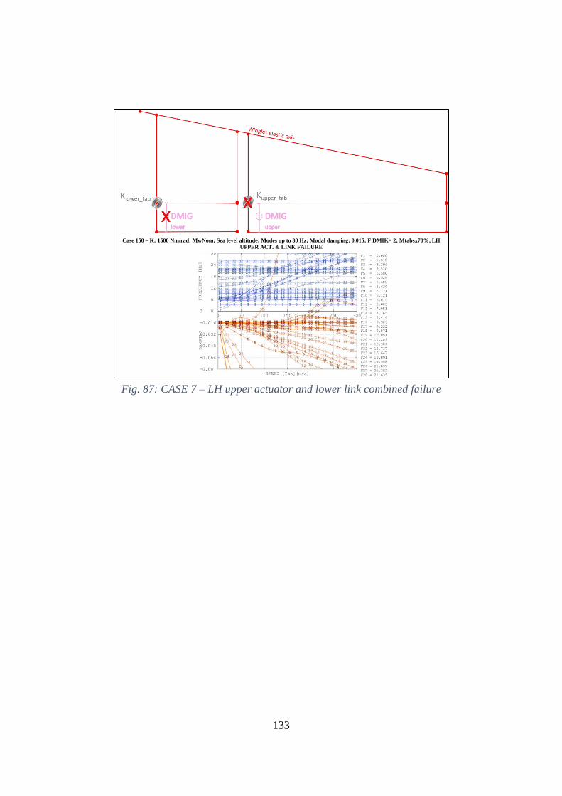
133
Fig. 87: CASE 7 – LH upper actuator and lower link combined failure
Case 150 – K: 1500 Nm/rad; MwNom; Sea level altitude; Modes up to 30 Hz; Modal damping: 0.015; F DMIK= 2; Mtabsx70%, LH
UPPER ACT. & LINK FAILURE
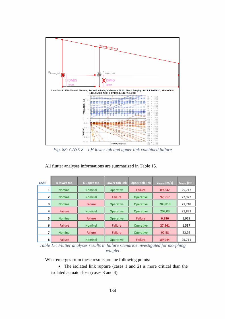
134
Fig. 88: CASE 8 – LH lower tab and upper link combined failure
All flutter analyses informations are summarized in Table 15.
CASE K lower tab K upper tab Lower tab link Upper tab link vflutter [m/s] fflutter [Hz ]
1 Nominal Nominal Operative Failure 89,842 25,717
2 Nominal Nominal Failure Operative 92,517 22,922
3 Nominal Failure Operative Operative 203,819 21,718
4 Failure Nominal Operative Operative 208,03 21,831
5 Nominal Failure Operative Failure 6,886 1,919
6 Failure Nominal Failure Operative 27,541 1,587
7 Nominal Failure Failure Operative 92,58 22,92
8 Failure Nominal Operative Failure 89,944 25,711
Table 15: Flutter analyses results in failure scenarios investigated for morphing
winglet
What emerges from these results are the following points:
• The isolated link rupture (cases 1 and 2) is more critical than the
isolated actuator loss (cases 3 and 4);
Case 150 – K: 1500 Nm/rad; MwNom; Sea level altitude; Modes up to 30 Hz; Modal damping: 0.015; F DMIK= 2; Mtabsx70%,
LH LOWER ACT. & UPPER LINK FAILURE
135
• Upper link rupture (case 1) is more critical than the lower one (case
2);
• Actuator and link combined rupture, both belonging to upper tabs or
lower tabs (cases 5 and 6), is the most critical event possible among the ones
analyzed.
• Lower (upper) actuator loss, in combination with upper (lower) link
rupture is a less critical event, if compared with the ones described in cases
five and six.
• The only aeroelastically safe events are cases 3 and 4.
The use of damping on actuators or on tabs is highly recommended for a reas-
sessment in compliance with the FHA severity.
136
7 Conclusions and Future Works
This thesis provides an extended aeroelastic assessment of two morphing wing
devices, flap and winglet, both integrated into a 90-seat turboprop (TP90)regional
transportation aircraft.
Experience teaches that due to the augmented Degree Of Freedoms (DOF),
morphing wings are more prone to aeroelastic instabilities than more conventional
architectures integrating passive counterparts. Non-classical effects may arise in
terms of flutter-instabilities due to the unconventional systems arrangement and
their mutual interaction, especially in malfunctioning or failure conditions.
This work followed an incremental criterion of problems to face; for this rea-
son, it was divided into five stages:
1. In order to perform flutter analyses, the A/C aeroelastic model was properly
generated. Rational approaches were adopted in terms of structural -stiff-
ness and inertial- properties extraction by preliminary Finite Elements
Models, referring to a stick-equivalent representation. Doublet Lattice
Method (DLM) was used to develop the A/C aerodynamic grid by means
of elementary units, called boxes. Superficial spline functions were then
adopted to interpolate modal displacements at the center of each aerody-
namic box.
2. A first campaign of trade-off analysis was performed on flap tabs, by con-
sidering the winglet at the loop 0 of the preliminary design configuration.
Combined variations were considered for flap tabs inertial and actuators
stiffness parameters. Obtained results showed the presence of several flutter
modes occurring at speeds lower than 1.25Vdive (200 m/s). The most critical
flutter modes were analyzed in terms of modal shapes; tabs mass-balancing
was identified as the best design solution to avoid the flutter.
3. A second campaign of trade-off analyses was carried out on winglet tabs,
while flap tabs were maintained at locked commands and for them the in-
ertial and stiffness configurations providing the lowest (and not critical)
flutter speeds were considered. Also in this case, inertial and stiffness pa-
rameters of the actuators were both made to vary .Most critical flutter
modes were identified and two design solutions were consequently sug-
gested for ensuring flutter clearance:
• Winglet tabs over-balancing;
• 100% increase of the stiffness of the interface plug between
wing/winglet
By comparing such solutions in terms of weight, the second one
results the most convenient (less winglet mass) and, for this reason,
137
it was considered as the nominal configuration for the loop 1 of the
preliminary design.
4. Further flutter analyses were carried out by simulating winglet actuators
free-play. For that purpose, harmonic balance method was adopted to
model actuators equivalent stiffness from a bi-linear law. Flutter speed re-
sulted out of the speed certification envelope in all the investigated cases.
5. Fault tree analyses were performed on morphing flap and winglet as iso-
lated devices to quantify the probability of particular failure scenarios and
to verify their eventual compliance with the airworthiness requirements.
Such studies drove the combined aeroelastic assessments by considering
several failure cases (isolated or combined link/actuator rupture). Gained
results showed that actuator failure is more critical than link rupture, and
the aeroelastic instability can be overcome by using proper damping de-
vices.
This activity shows the importance of aeroelastic trade-off analyses since the
early stages of the design process to properly size morphing systems, including kin-
ematics, masses and distributed stiffness of the morphing surfaces.
In a multidisciplinary framework involving aerodynamics, structures, actuation
architectures and control logics, aeroelastic instabilities analyses shall be integrated
in the design loop to maximize the critical speeds of flutter, predict divergence, and
control reversal of the morphing surfaces. The idea herein described leads the way
to further researches aimed at enhancing the TRL of a morphing wing concept. In
this regard, future steps may be:
• Aeroelastic refinements to guarantee flutter clearance using more ad-
vanced FE models;
• Aerodynamic model calibration by means of wind tunnel tests;
• Ground Vibration Test on morphing flap and adaptive winglet to obtain
experimentally modal characteristics, proving the accuracy of the
adopted schemes and the validity of aeroelastic instabilities;
• Mixed numerical-experimental flutter procedure to combine the most rel-
evant experimental modes to the numerical inertial distribution of morph-
ing flap and adaptive winglet.
• Combined fault tree analysis on morphing flaps and winglets by includ-
ing aircraft failures such as asymmetric inoperative engine or strong lat-
eral wind conditions;
• Assessment of the interaction among all smart tabs and aircraft primary
control devices (ailerons, elevator, rudder).
138
APPENDIX A – General Description of the Sandy code
SANDY is a currently not-commercial code developed by M. Pecora [3] Within
last twenty-five years, it was continuously optimized in order to meet industrial
requirements for static and dynamic aeroelastic and aero-servo-elastic analyses of
aircraft
A multidisciplinary environment - including rational approaches and validated
numerical methods - achieves the following main tasks:
• A/C dynamic model (structural model and inertial model) generation;
• A/C aerodynamic model generation;
• Accurate transfer matrices interfacing between dynamic and aerody-
namic models generation;
• A/C acceleration and loads response due to flight and ground maneuver
and/or gust evaluation;
• A/C static and dynamic acceleration and loads response assessment to
movable lifting surfaces deflections imposed by mechanical and/or
electro-mechanical control circuits;
• Divergence, control reversal and flutter speeds evaluation.
The computational tool and numerical methods also gives the possibility to
carry out fast analyses by investigating the A/C aeroelastic impact of combined
design parameters. In this way, trade-off aeroelastic analyses can be achieved
changing structural and dynamic properties relative to A/C components.
Sandy operates in Visual Fortran® / Matlab® environment, allowing highly
efficient computational intercommunicating routines to evaluate:
• Static design loads for rigid and elastic aircraft;
• Turbulence-induced dynamic loads;
• Aeroelastic instabilities, also including command control laws by
means of several methodologies.
Four macro-modules are present in its structure:
• Dynamic module;
• Aerodynamic module;
139
• Aeroelastic module.
• Plot visualization module.
Dynamic module generates A/C structural and inertial models and internally
FE evaluates A/C modal parameters. For the sake of time optimization and model
reliability, only two typologies of elements can be used:
• mono-dimensional elements (beam, rod, rigid-link, spring);
• DMIG (Direct Matrix Input at Grids) elements for a correct evaluation
of stiffness and inertial properties of all those parts for which a mono-
dimensional elements modelling leads to high approximations and/or is
not applicable at all.
The dynamic module offers also the possibility to import DMIG elements and
A/C modal parameters - modes shapes, frequencies, generalized masses, damping
(also extractable by ground vibration tests) - by commercial FE software (e.g.:
MSC-NASTRAN ®).
The introduction of extra-modes representing movable surfaces deflection is
allowed in dynamic module, in addition to the normal modes related to A/C struc-
ture.
The aerodynamic module generates the aerodynamic model and evaluates
modal pressure distributions by means of Doublet Lattice Method.
In such a way, three-dimensional compressible aerodynamic models as well as
the possibility of performing local corrections in pressure distributions can be ac-
complished in order to achieve a correct simulation of movable surfaces aerody-
namics (as recommended by FAA AC 25.629-1A paragraph 6).
The aeroelastic module is finally constituted by all the routines devoted to:
• the interpolation of modal displacements on the aerodynamic lattice
(matching routines implementing 3D spline methodologies);
• the evaluation of generalized aerodynamic pressures/forces and
steady/unsteady aerodynamic influence coefficients;
• the solution of aeroelastic equations related to A/C aeroelastic response
and aeroelastic instabilities identification.
Software overall accomplishments have been successfully proved, in terms of
theoretical and experimental aeroelastic stability, during the certification processes
of several commercial aircrafts.
140
APPENDIX B - CS 23.629 Flutter
For the sake of completeness, European airworthiness section regarding flut-
ter analyses is reported.
(See AMC 23.629)
(a) It must be shown by the methods of (b) and either (c) or (d) , that the aero-
plane is free from flutter, control reversal and divergence for any condition of op-
eration within the limit V-n envelope and at all speeds up to the speed specified for
the selected method. In addition –
(1) Adequate tolerances must be established for quantities which affect flutter;
including speed, damping, mass balance and control system stiffness; and
(2) The natural frequencies of main structural components must be determined
by vibration tests or other approved methods.
(b) Flight flutter tests must be made to show that the airplane is free from flutter,
control reversal and divergence and to show by these tests that –
(1) Proper and adequate attempts to induce flutter have been made within the
speed range up to VD;
(2) The vibratory response of the structure during the test indicates freedom
from flutter;
(3) A proper margin of damping exists at VD; and
(4) There is no large and rapid reduction in damping as VD is approached.
(c) Any rational analysis used to predict freedom from flutter, control reversal
and divergence must cover all speeds up to 1·25 VD.
(d) Compliance with the rigidity and mass balance criteria (pages 4-12), in Air-
frame and Equipment Engineering Report No. 45 (as corrected) “Simplified Flutter
Prevention Criteria” (published by the Federal Aviation Administration) may be
accomplished to show that the aeroplane is free from flutter, control reversal, or
divergence if –
(1) VD/MD for the aeroplane is less than 482 km/h (260 knots) (EAS) and less
than Mach 0·5;
(2) The wing and aileron flutter prevention criteria, as represented by the wing
torsional stiffness and aileron balance criteria, are limited to use to aeroplanes with-
out large mass concentrations (such as engines, floats, or fuel tanks in outer wing
panels) along the wing span; and
(3) The aeroplane –
(i) Does not have a T-tail or other unconventional tail configurations;
141
(ii) Does not have unusual mass distributions or other unconventional design
features that affect the applicability of the criteria; and
(iii) Has fixed-fin and fixed-stabiliser surfaces.
(e) For turbo-propeller powered aeroplanes, the dynamic evaluation must in-
clude –
(1) Whirl mode degree of freedom which takes into account the stability of the
plane of rotation of the propeller and significant elastic, inertial and aerodynamic
forces; and
(2) Propeller, engine, engine mount and aeroplane structure stiffness and damp-
ing variations appropriate to the particular configuration.
(f) Freedom from flutter, control reversal and divergence up to VD/MD must be
shown as follows:
(1) For aeroplanes that meet the criteria of sub-paragraphs (d) (1) to (d) (3),
after the failure, malfunction, or disconnection of any single element in any tab
control system.
(2) For aeroplanes other than those described in sub-paragraph (f) (1), after the
failure, malfunction, or disconnection of any single element in the primary flight
control system, any tab control system, or any flutter damper.
(g) For aeroplanes showing compliance with the fail-safe criteria of CS 23.571
and 23.572, the aeroplane must be shown by analysis to be free from flutter up to
VD/MD after fatigue failure, or obvious partial failure of a principal structural ele-
ment.
(h) For aeroplanes showing compliance with the damage-tolerance criteria of
CS 23.573, the aeroplane must be shown by analysis to be free from flutter up to
VD/MD with the extent of damage for which residual strength is demonstrated.
(i) For modifications to the type design which could affect the flutter charac-
teristics compliance with sub-paragraph (a) must be shown, except that analysis
alone, which is based on previously approved data, may be used to show freedom
from flutter, control reversal and divergence for all speeds up to the speed specified
for the selected method.
Advisory Circular AC No: 23.629-1A
Advisory Circular presents definitions and procedures to respond to 23.629
section:
2. SPECIAL DESIGN.
The special design category includes airplanes with certain design features that
experience has shown warrant special consideration with regard to flutter. Flutter
free operation for these special unconventional configurations may be shown by
analyses which include an assessment of the effects of critical parameters. Flight
142
flutter tests to supplement those analyses are recommended. Some of these special
unconventional configurations are:
a. Any aircraft with a design dive speed of 260 knots15 (EAS) or more at alti-
tudes below 14,000 feet16 and Mach 0.6 or more at altitudes at and above 14,000
feet.
b. Any aircraft approved for flight in icing conditions. (The effect of ice accre-
tions on unprotected surfaces, including those which might occur during system
malfunctions, should be considered).
c. Pusher powerplants.
d. Canard geometry.
e. T, V, X, H, or any other unusual tail configuration.
f. Any external pods or stores mounted to wing or other major aerodynamic
surface a
g. Fuel tanks outboard of 50% semispan.
h. Tabs which do not meet the irreversibility criteria of chapter 2, paragraph
3.d., and of reference 1, appendix 4.
i. Spring tabs.
j. All-movable tails, i.e., stabilators.
k. Slender boom or twin-boom fuselages.
1. Multiple-articulated control surfaces.
m. Wing spoilers.
n. Hydraulic control Systems with stability augmentation.
0. Full span flaps.
p. Leading edge devices (i.e., slots, etc.).
q. Geared tabs (servo or anti-servo, etc.).
4. Rational Analysis.
a. Review of Past Analysis. Review of previous flutter analyses conducted upon
similar aircraft can provide the engineer with useful information regarding trends,
critical modes, etc. Although in general such a review is not used as a substantiation
basis for a new aircraft, it can provide a useful tool in evaluating the effect of mod-
ifications to existing certified aircraft.
b. Two-Dimensional Analysis. The flutter characteristics of straight wings (or
tails) of large aspect ratio can be predicted reasonably well by considering a "rep-
resentative section that has two or three degrees of freedom. Translation and pitch
are always needed and) for control surfaces, the third freedom would be rotation
about the hinge line.
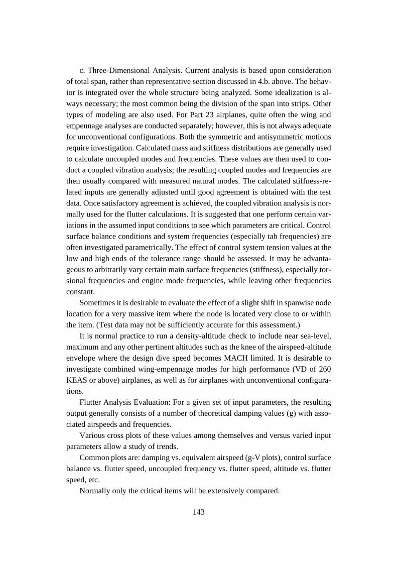
143
c. Three-Dimensional Analysis. Current analysis is based upon consideration
of total span, rather than representative section discussed in 4.b. above. The behav-
ior is integrated over the whole structure being analyzed. Some idealization is al-
ways necessary; the most common being the division of the span into strips. Other
types of modeling are also used. For Part 23 airplanes, quite often the wing and
empennage analyses are conducted separately; however, this is not always adequate
for unconventional configurations. Both the symmetric and antisymmetric motions
require investigation. Calculated mass and stiffness distributions are generally used
to calculate uncoupled modes and frequencies. These values are then used to con-
duct a coupled vibration analysis; the resulting coupled modes and frequencies are
then usually compared with measured natural modes. The calculated stiffness-re-
lated inputs are generally adjusted until good agreement is obtained with the test
data. Once satisfactory agreement is achieved, the coupled vibration analysis is nor-
mally used for the flutter calculations. It is suggested that one perform certain var-
iations in the assumed input conditions to see which parameters are critical. Control
surface balance conditions and system frequencies (especially tab frequencies) are
often investigated parametrically. The effect of control system tension values at the
low and high ends of the tolerance range should be assessed. It may be advanta-
geous to arbitrarily vary certain main surface frequencies (stiffness), especially tor-
sional frequencies and engine mode frequencies, while leaving other frequencies
constant.
Sometimes it is desirable to evaluate the effect of a slight shift in spanwise node
location for a very massive item where the node is located very close to or within
the item. (Test data may not be sufficiently accurate for this assessment.)
It is normal practice to run a density-altitude check to include near sea-level,
maximum and any other pertinent altitudes such as the knee of the airspeed-altitude
envelope where the design dive speed becomes MACH limited. It is desirable to
investigate combined wing-empennage modes for high performance (VD of 260
KEAS or above) airplanes, as well as for airplanes with unconventional configura-
tions.
Flutter Analysis Evaluation: For a given set of input parameters, the resulting
output generally consists of a number of theoretical damping values (g) with asso-
ciated airspeeds and frequencies.
Various cross plots of these values among themselves and versus varied input
parameters allow a study of trends.
Common plots are: damping vs. equivalent airspeed (g-V plots), control surface
balance vs. flutter speed, uncoupled frequency vs. flutter speed, altitude vs. flutter
speed, etc.
Normally only the critical items will be extensively compared.
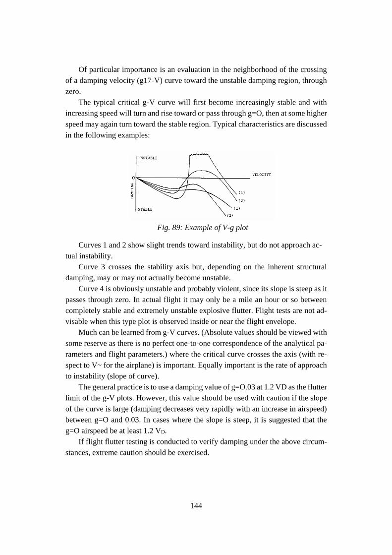
144
Of particular importance is an evaluation in the neighborhood of the crossing
of a damping velocity (g17-V) curve toward the unstable damping region, through
zero.
The typical critical g-V curve will first become increasingly stable and with
increasing speed will turn and rise toward or pass through g=O, then at some higher
speed may again turn toward the stable region. Typical characteristics are discussed
in the following examples:
Fig. 89: Example of V-g plot
Curves 1 and 2 show slight trends toward instability, but do not approach ac-
tual instability.
Curve 3 crosses the stability axis but, depending on the inherent structural
damping, may or may not actually become unstable.
Curve 4 is obviously unstable and probably violent, since its slope is steep as it
passes through zero. In actual flight it may only be a mile an hour or so between
completely stable and extremely unstable explosive flutter. Flight tests are not ad-
visable when this type plot is observed inside or near the flight envelope.
Much can be learned from g-V curves. (Absolute values should be viewed with
some reserve as there is no perfect one-to-one correspondence of the analytical pa-
rameters and flight parameters.) where the critical curve crosses the axis (with re-
spect to V~ for the airplane) is important. Equally important is the rate of approach
to instability (slope of curve).
The general practice is to use a damping value of g=O.03 at 1.2 VD as the flutter
limit of the g-V plots. However, this value should be used with caution if the slope
of the curve is large (damping decreases very rapidly with an increase in airspeed)
between g=O and 0.03. In cases where the slope is steep, it is suggested that the
g=O airspeed be at least 1.2 VD.
If flight flutter testing is conducted to verify damping under the above circum-
stances, extreme caution should be exercised.

145
For damping curves such as (3), which peak out below 1.2 VD, the predicted
damping should be no more unstable than g=O.02 unless justification is provided
by other acceptable means.
146
References
[1] Pecora, R., “Multi-modal morphing wing flaps for next generation green regional air-
craft: the Cleansky challenge”, Proceedings of the ASME 2018 Conference on Smart
Materials, Adaptive Structures and Intelligent Systems SMASIS2018 September 10-
12, 2018, San Antonio, TX, USA.
[2] European Aviation Safety Agency, Certification Specifications and Acceptable Means
of Compliance for Large Aeroplanes – CS-25, Amendment 11, July 2011.
[3] Pecora, R., Amoroso, F., Noviello, M. C., Concilio, A., Dimino, I., “Aeroelastic sta-
bility analysis of a large civil aircraft equipped with morphing winglets and adaptive
flap tabs”, Proceedings of SPIE. 10595, Active and Passive Smart Structures and In-
tegrated Systems XII, March 2018.
[4] Bisplinghoff, R. L., Ashley, H., Halfman, R. L., “Aeroelasticity”, Dover Publications,
Inc., 1955.
[5] Roger, K. L., “Airplane Math Modeling and Active Aeroelastic Control Design,” Pro-
ceedings of AGARD CP-228, pp. 1–11, 1977.
[6] Browman, J., Sanders, B., and Weisshaar, T., “Evaluating the Impact of Morphing
Technologies on Aircraft Performance”, Proceedings of the Forty-Third AIAA Con-
ference on Structures, Structural Dynamics and Materials, AIAA Paper 2002-1631,
April 2002.
[7] Raymer, D. “Aircraft Design: A Conceptual Approach”, AIAA Education Series,
Fourth edition, 2006.
[8] Yang R. J. and Chahande A. I., “Automotive applications of topology optimization”.
Journal of Structural and Multidisciplinary Optimization, 9:245–249, 1995.
[9] Bendsoe, M. P., “Optimal shape design as a material distribution problem”, Journal of
Structural Optimization, 1:193–202, 1989.
[10] Lu K. and Kota S., “Parameterization strategy for optimization of shape morphing
compliant mechanisms using load path representation”. Proceedings of ASME Design
Engineering Technical Conference, DETC2003/DAC-48775, 2003.
[11] Bendsoe, M. and Sigmund, O., “Topology Optimization: Theory, Methods and Appli-
cations”. Springer-Verlag Berlin, 2004.
[12] Sigmund, O., “Morphology-based black and white filters for topology optimization”.
Journal of Structural and Multidisciplinary Optimization, 33:401–424, 2006.
[13] Kharal, A. and Saleem, A., “Neural networks based airfoil generation for a given CP
using Bezier-PARSEC parameterization”, Journal of Aerospace Science and Technol-
ogy, 2011.
[14] Huyse, L. and Lewis, R. “Aerodynamic Shape Optimization of Two-dimensional Air-
foils Under Uncertain Conditions”, NASA ICASE Report No. 2001-1, pages 1–8,
2001.
[15] Zingg, D. W. and Elias, S., “Aerodynamic Optimization Under a Range of Operating
Conditions”, AIAA Journal, 44:2787–2792, 2006.
[16] Trenker, M. “Design Concepts for Adaptive Airfoils with Dynamic Transonic Flow
Control”, Journal of Aircraft, 40:734–740, 2003.
[17] Wadehn, W., Sommerer, A., Lutz, T., Fokin, G., Pritschow, S. and Wagner, S. “Struc-
tural concepts and aerodynamic design of shock control bumps”, Proceedings of ICAS
Congress, 2002.
147
[18] Hodges, D. H. and Pierce, G. A., “Introduction to Structural Dynamics and Aeroelas-
ticity”, Cambridge University Press (Aerospace Series), 2002.
[19] Pederson, C. B. W., Buhl, T. and Sigmund, O., “Topology synthesis of large-displace-
ment compliant mechanisms”, Journal of Numerical Methods in Engineering,
50:2683–2705, 2001.
[20] Della Vecchia, P., Corcione, S., Pecora, R., Nicolosi, F., Dimino, I., Concilio, A., “De-
sign and integration sensitivity of a morphing trailing edge on a reference airfoil: The
effect on high-altitude long-endurance aircraft performance”, Journal of Intelligent
Material Systems and Structures, Vol. 28, Issue 20, 2017.
[21] Sofla, A., Meguid, S., Tan, K., and Yeo, W., “Shape morphing of aircraft wing: Status
and challenges. Journal of Materials and Design”, 31:1284–1292, 2010.
[22] Bye, D. R. and McClure, P. D., “Design of a Morphing Vehicle”, Proceedings of. 48th
AIAA Structures, Structural Dynamics, and Materials Conference, AIAA 2007-1728,
2007.
[23] Prock, T., Weisshaar, A. and Crossley, W. A., “Morphing airfoil shape change opti-
mization with minimum actuator energy as an objective”, Proceedings of 9th AIAA
Symposium on Multidisciplinary Analysis and Optimization, AIAA 2002-5401, 2002.
[24] Jacob, J., Simpson, A. and Smith, S. “Design and Flight Testing of Inflatable Wings
with Wing Warping”, Society of Automotive Engineers, 05WAC-61, 2005.
[25] Blondeau, J., Richeson, J. and Pines, D. “Design, development and testing of a morph-
ing aspect ratio wing using an inflatable telescopic spar”, Proceedings of 44th AIAA
Structures, Structural Dynamics, and Materials Conference, AIAA 2003-1718, 2003.
[26] Bye, D. R. and McClure, P. D., “Design of a Morphing Vehicle”, Proceedings of 48th
AIAA Structures, Structural Dynamics, and Materials Conference, AIAA 2007-1728,
2007.
[27] Skillen, M. D. and Crossley, W. A., “Modelling and Optimization for Morphing Wing
Concept Generation”, The Langley Research Centre NASA, NASA/CR-2007-
214860, 2007.
[28] Garcia, H., Abdulrahim, M. and Lind, R., “Roll control for a micro air vehicle using
active wing morphing”, Proceedings of AIAA Guidance, Navigation, and Control
Conference Exhibit, AIAA- 2003-5347, 2003.
[29] Clean Sky2 program official website: www.cleansky.eu
[30] De Gaspari, A., Gilardelli, A., Ricci, S., Airoidi, A., “Design of a leading edge morph-
ing based on compliant structures in the framework of the CS2-AIRGREEN2 project”,
Proceedings of the ASME 2018 Conference on Smart Materials, Adaptive Structures
and Intelligent Systems SMASIS2018 September 10-12, 2018, San Antonio, TX,
USA.
[31] Noviello, M. C., Dimino, I., Amoroso, F., Concilio, A., Pecora, R., “Preliminary as-
sessment of morphing winglet and flap tabs influence on the aeroelastic stability of
next generation regional aircraft”, Proceedings of the ASME 2018 Conference on
Smart Materials, Adaptive Structures and Intelligent Systems SMASIS2018 Septem-
ber 10-12, 2018, San Antonio, TX, USA.
[32] Rea, F., Amoroso, F., Pecora, R., Noviello, M. C., Arena, M., “Structural design of a
multifunctional morphing fowler flap for a twin-prop regional aircraft”, Proceedings
of the ASME 2018 Conference on Smart Materials, Adaptive Structures and Intelli-
gent Systems SMASIS2018 September 10-12, 2018, San Antonio, TX, USA.

148
[33] Pecora, R., Amoroso, F., Amendola, F. and Concilio, A., “Validation of a smart struc-
tural concept for wing-flap camber morphing,” Smart Structures and Systems, vol. 14,
no. 4, pp. 659–678, 2014.
[34] Rea, F., Amoroso, F., Pecora, R., Kintscher, M., “Design of an adaptive twist trailing
edge for large commercial aircraft applications”, Proceedings of the ASME 2018 Con-
ference on Smart Materials, Adaptive Structures and Intelligent Systems
SMASIS2018 September 10-12, 2018, San Antonio, TX, USA.
[35] Rudolph, P.K.C., “High-lift systems on commercial subsonic airliners”, Technical Re-
port, NASA-CR-4746, 1996.
[36] Amendola, G., Dimino, I., Concilio, A., Pecora, R., Cascio, M.L., “Preliminary design
process for an adaptive winglet”, International Journal of Mechanical Engineering and
Robotics Research, 2018.
[37] Dimino, I., Amendola, G., Di Giampaolo, B., Iannaccone, G., Lerro, A., “Preliminary
design of an actuation system for a morphing winglet”, Proceedings of 8th Interna-
tional Conference on Mechanical and Aerospace Engineering (ICMAE), pp. 416-422,
2017.
[38] Dimino, I., Ameduri, S., Concilio, A., “Preliminary failure analysis and structural de-
sign of a morphing winglet for green regional aircraft”, Proceedings of the ASME
2018 Conference on Smart Materials, Adaptive Structures and Intelligent Systems
SMASIS2018 September 10-12, 2018, San Antonio, TX, USA.
[39] Amendola, G; Dimino, Ignazio, Concilio, Antonio, Andreutti, G, Pecora, Rosario, Lo
Cascio, M., “Preliminary design process for an adaptive winglet”, International Jour-
nal of Mechanical Engineering and Robotics Research, 7. 83-92.
10.18178/ijmerr.7.1.83-92, 2018.
[40] Lo Cascio, M., MSc Thesis, “Ottimizzazione Topologica del Trailing Edge Adattivo
di una Winglet Morphing”, University of Palermo, 2017.
[41] Pecora, M., “Modellistica aeroelastica per analisi di flutter”, Documento Tecnico In-
terno CIRA, CIRA-TR-05-0101, 2005.
[42] Roger, K., “Airplane Math Modelling Methods for Active Control Design,” Structural
Aspects of Control, AGARD Conference Proceeding, Vol. 9, pp. 4.1, 1977.
[43] Pecora, M., “Dispense del corso di Aeroelasticità applicata tenuto presso la Seconda
Università degli Studi di Napoli a.a. 2000/2001”, 2001.
[44] MSC/MD NASTRAN®, Software Package, Ver. R3-2006, “Reference Manual”.
[45] SAE ARP 4754a (2010) US SAE international, guidelines for development of civil
aircraft and systems, Revised Dec 2010.
[46] SAE ARP 4761 (1996) US SAE international, guidelines and methods for conducting
the safety assessment process on civil airborne systems and equipment, Dec 1996.
[47] Verrastro, M., Metge, S., “Morphing Wing Integrated Safety Approach and Results”,
Smart Intelligent Aircraft Structures (SARISTU), pp. 43-69, 2015.
[48] Reliability Workbench Reference Manual.
[49] Palmieri M., Pispola, G., Dimino, I., “Contribution to final specifications of the
morphing winglet actuation system”, Airgreen 2 Project Deliverable O 2.1.2-18, 2018.
Recommended