Host Controller TCP/IP Communication Protocol User Manual Addendum, Moving Path Node
Host Controller TCP/IP Communication Protocol
User Manual Addendum, Moving Path Node
10004475707 Ver. 00 MMI-UM033A-EN-P
Copyright © 2019 Rockwell Automation, Inc. Page 2 of 45
Document: 10004475707; MMI-UM033A-EN-P
Version: 00
Host Controller TCP/IP Communication Protocol
User Manual Addendum, Moving Path Node
10004475707 Ver. 00 MMI-UM033A-EN-P
Copyright © 2019 Rockwell Automation, Inc. Page 3 of 45
Although every effort is made to keep this manual accurate and up-to-date, MagneMotion®
assumes no responsibility for any errors, omissions, or inaccuracies. Information that is
provided in this manual is subject to change without notice. Any sample code that is
referenced in this manual or included with MagneMotion software is included for illustration
only and is, therefore, unsupported.
MagneMotion®, MagneMover®, QuickStick®, MML™, MM LITE™, and SYNC IT™ are
trademarks or registered trademarks of MagneMotion, a Rockwell Automation Company.
Rockwell Automation® is a registered trademark of Rockwell Automation, Inc. Microsoft®
and Windows® are registered trademarks of Microsoft Corporation. EtherNet/IP™ is a
trademark of ODVA®, Inc. All other trademarks are properties of their respective owners.
This product is protected under one or more U.S. and International patents. Additional U.S.
and International patents pending.
Copyright © 2019 MagneMotion, Inc., a Rockwell Automation Company. All Rights
Reserved. The information that is included in this manual is proprietary or confidential to
Rockwell Automation, Inc. Any disclosure, reproduction, use, or redistribution of this
information by or to an unintended recipient is prohibited.
MagneMotion, Inc.
A Rockwell Automation Company
139 Barnum Road
Devens, MA 01434
USA
Phone: +1 978-757-9100
Fax: +1 978-757-9200
www.magnemotion.com
Host Controller TCP/IP Communication Protocol
User Manual Addendum, Moving Path Node
10004475707 Ver. 00 MMI-UM033A-EN-P
Copyright © 2019 Rockwell Automation, Inc. Page 4 of 45
Contents Purpose ...................................................................................................................................... 6
Reference Documents ............................................................................................................... 6
Definitions................................................................................................................................. 6
Application Notes ..................................................................................................................... 8
Moving Path Node .............................................................................................................. 8
Support ................................................................................................................................ 8
Open Ended Parallel Moving Paths .................................................................................... 9
Moving Paths Spanning Gap between Fixed Paths .......................................................... 10
Node Operation ................................................................................................................. 12
Path Linking/Unlinking .................................................................................................... 12
Entry Gates and Clearance Distances ............................................................................... 13
Entry Gates.................................................................................................................. 13
Clearance Distances .................................................................................................... 14
Protected Areas ........................................................................................................... 14
Path Startup Considerations .............................................................................................. 14
Communication Protocol ........................................................................................................ 16
Host Controller to HLC Communications ........................................................................ 16
MP Get Path End Status (0xBF 09 01) ....................................................................... 17
MP Link Command (0xBF 09 02) .............................................................................. 19
MP Unlink Command (0xBF 09 03) .......................................................................... 23
HLC to Host Controller Communications ........................................................................ 26
Command Status (0xD0)............................................................................................. 27
MP Path End Status Report (0xDF 09 01) .................................................................. 30
MP Alignment Request (0xDF 09 02) ........................................................................ 36
MP Path End States ................................................................................................................. 39
HLC Error Status Codes ......................................................................................................... 42
More Information .................................................................................................................... 43
Rockwell Automation Support ............................................................................................... 44
Figures Figure 1: Single Moving Path Node ......................................................................................... 9
Figure 2: Moving Path Node Pair ........................................................................................... 10
Figure 3: Path Linking/Unlinking in Moving Path Node ....................................................... 12
Figure 4: Node Entry Gates and Clearances ........................................................................... 14
Host Controller TCP/IP Communication Protocol
User Manual Addendum, Moving Path Node
10004475707 Ver. 00 MMI-UM033A-EN-P
Copyright © 2019 Rockwell Automation, Inc. Page 5 of 45
Tables Table 1: Moving Path Node Terminology ................................................................................ 6
Table 2: Host Controller to HLC Commands ......................................................................... 16
Table 3: HLC to Host Controller Status Responses................................................................ 26
Table 4: HLC to Host Controller Command Requests ........................................................... 26
Table 5: Path End State ........................................................................................................... 39
Table 6: HLC Command Status Codes ................................................................................... 42
Host Controller TCP/IP Communication Protocol
User Manual Addendum, Moving Path Node
10004475707 Ver. 00 MMI-UM033A-EN-P
Copyright © 2019 Rockwell Automation, Inc. Page 6 of 45
Purpose
This document is an addendum to the Host Controller TCP/IP Communication Protocol User
Manual and describes the additions to the protocol for communication between the
MagneMotion® HLC and a host controller (general-purpose computer) that is equipped with
a TCP/IP interface.
An additional node type, the Moving Path node has been added. New commands and
responses have been added to the communication protocol used between the host controller
and the HLC to support the use of Moving Path nodes.
Reference Documents
990000436, Host Controller TCP/IP Communication Protocol User Manual
990000559, QuickStick Configurator User Manual
Definitions
Table 1: Moving Path Node Terminology
Term Definition
Clearance Distance The distance from a node where the trailing edge of a vehicle is considered cleared from the node.
Control Path The Control Path is the path that is specified in an MP Link command from the host controller to link a junction. Once linked, this path remains the Control Path for the life of the junction until the junction transitions to the unlinked state.
Entry Gate The position on a path associated with a node where the leading edge of a vehicle is considered cleared from the node.
Entry Path An Entry Path is a path whose downstream end is a member of a node. A vehicle that is moving downstream enters a node on an Entry Path.
Entry Request When the headway for a vehicle reaches an entry gate, an entry request is made. The vehicle is not granted permission to move beyond the entry gate until the state machine for the Moving Path node grants permission.
Equivalent-Route Path
A path in a set of Moving Path node member paths that all offer a route to any destination reachable via any other path in the set.
Exit Path An Exit Path is a path whose upstream end is a member of a node. A vehicle that is moving downstream exits a node on an Exit Path.
Fixed Path A path whose position is fixed in the track layout.
Host Controller TCP/IP Communication Protocol
User Manual Addendum, Moving Path Node
10004475707 Ver. 00 MMI-UM033A-EN-P
Copyright © 2019 Rockwell Automation, Inc. Page 7 of 45
Table 1: Moving Path Node Terminology
Term Definition
Headway The space that is maintained before a vehicle to make sure that the vehicle is able to stop safely.
Link/Unlink When a Moving Path node junction is linked, the node controller forwards motor-to-motor messages between the path ends that are linked, which allows vehicle headway to advance through the junction. When unlinked, motor-to-motor messages are not forwarded, which causes vehicles that are ordered through a junction to become obstructed until the junction is linked.
Linked Path Junction The aligned junction between two path members of a Moving Path node where motor-to-motor communication is being forwarded.
Moving Path A path that is moved to align with the end of another path.
Moving Path Junction The junction where a moving path end is linked to another path end.
Moving Path Node A node where one or more downstream path ends can align with one or more upstream path ends. A host controller controls the moving path positions to effect path end alignment.
Moving Path Node Member Path Limit
The maximum number of configured member paths for a Moving Path node.
Moving Path Node Pair
Two Moving Path nodes, one at the upstream end of a set of one or more moving paths and one at the downstream end of the same set of moving paths.
Peer Node Reported in the Path End status. It is the node at the opposite end of a moving path.
Peer Path The path on the opposite side of a junction from the Control Path, is the path that is specified in a link command from the host controller to link a junction. Once linked, this path remains the Peer Path for the life of the junction until the junction transitions to the unlinked state.
Platooning When a vehicle is following another vehicle through a node, platooning allows the trailing vehicle to follow the leading vehicle while maintaining brick wall headway.
Protected Area The area around a node that is defined by the entry gates and clearance distances. This area is used to make sure that vehicles do not collide with other vehicles in the node or with the mechanism that is related to the node.
Specific-Route Path A path in a set of Moving Path node member paths where destinations reachable via some paths in the set are not reachable by all paths in the set.
Unlinked Path Junction
The junction between two path members of a Moving Path node where motor-to-motor communication is not being forwarded.
Host Controller TCP/IP Communication Protocol
User Manual Addendum, Moving Path Node
10004475707 Ver. 00 MMI-UM033A-EN-P
Copyright © 2019 Rockwell Automation, Inc. Page 8 of 45
Application Notes
Moving Path Node
A Moving Path node is used to support track topologies where a user-supplied mechanism is
used to move one of the guideways. The Moving Path node provides support to route
vehicles across moving paths to their destination. There is a Moving Path node at each end of
a moving path where vehicles move onto or off the moving path. As with other node types,
the paths in the Moving Path node are identified as Entry Paths and Exit Paths. A user-
supplied mechanism supports and moves the moving path and aligns the end of the moving
path with a fixed guideway, which allows vehicles to move onto and off the moving path.
The ends of all paths in the node must be connected to the same node controller. See Figure 1
and Figure 2 where the shaded areas represent Moving Path nodes.
NOTE: Depending upon the configuration of the Moving Path node, the moving path can
be either an Entry Path or an Exit Path.
In the example in Figure 1, with one Moving Path node, the vehicles move from a fixed path
(defined in the Moving Path node configuration as the Entry Path) and enter the moving path
(defined in the Moving Path node configuration as the Exit Path).
In the example in Figure 2, with two Moving Path nodes, the vehicles move from a fixed
path (defined in the Moving Path node configuration for the first node as the Entry Path) and
enter the moving path (defined in the Moving Path node configuration for the first node as
the Exit Path). The vehicles then move from the moving path (defined in the Moving Path
node configuration for the second node as the Entry Path) and enter a fixed path (defined in
the Moving Path node configuration for the second node as the Exit Path).
NOTE: The moving path is mounted to a user-supplied mechanism that is controlled by
the host controller. This mechanism could be a MagneMotion LSM.
Support
This node type is supported in the latest software release for the following product line:
QuickStick® 100 transport systems.
Host Controller TCP/IP Communication Protocol
User Manual Addendum, Moving Path Node
10004475707 Ver. 00 MMI-UM033A-EN-P
Copyright © 2019 Rockwell Automation, Inc. Page 9 of 45
Open Ended Parallel Moving Paths
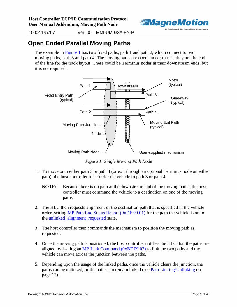
The example in Figure 1 has two fixed paths, path 1 and path 2, which connect to two
moving paths, path 3 and path 4. The moving paths are open ended; that is, they are the end
of the line for the track layout. There could be Terminus nodes at their downstream ends, but
it is not required.
Figure 1: Single Moving Path Node
1. To move onto either path 3 or path 4 (or exit through an optional Terminus node on either
path), the host controller must order the vehicle to path 3 or path 4.
NOTE: Because there is no path at the downstream end of the moving paths, the host
controller must command the vehicle to a destination on one of the moving
paths.
2. The HLC then requests alignment of the destination path that is specified in the vehicle
order, setting MP Path End Status Report (0xDF 09 01) for the path the vehicle is on to
the unlinked_alignment_requested state.
3. The host controller then commands the mechanism to position the moving path as
requested.
4. Once the moving path is positioned, the host controller notifies the HLC that the paths are
aligned by issuing an MP Link Command (0xBF 09 02) to link the two paths and the
vehicle can move across the junction between the paths.
5. Depending upon the usage of the linked paths, once the vehicle clears the junction, the
paths can be unlinked, or the paths can remain linked (see Path Linking/Unlinking on
page 12).
Downstream
User-supplied mechanism
Fixed Entry Path (typical)
Moving Exit Path (typical)
Motor (typical)
Moving Path Node
Guideway (typical)
Path 1
Path 2 Path 4
Path 3
Node 1
Moving Path Junction
Host Controller TCP/IP Communication Protocol
User Manual Addendum, Moving Path Node
10004475707 Ver. 00 MMI-UM033A-EN-P
Copyright © 2019 Rockwell Automation, Inc. Page 10 of 45
Moving Paths Spanning Gap between Fixed Paths
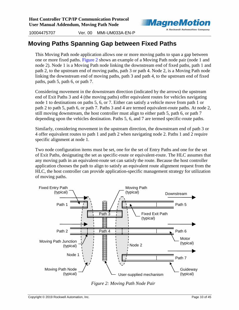
This Moving Path node application allows one or more moving paths to span a gap between
one or more fixed paths. Figure 2 shows an example of a Moving Path node pair (node 1 and
node 2). Node 1 is a Moving Path node linking the downstream end of fixed paths, path 1 and
path 2, to the upstream end of moving paths, path 3 or path 4. Node 2, is a Moving Path node
linking the downstream end of moving paths, path 3 and path 4, to the upstream end of fixed
paths, path 5, path 6, or path 7.
Considering movement in the downstream direction (indicated by the arrows) the upstream
end of Exit Paths 3 and 4 (the moving paths) offer equivalent routes for vehicles navigating
node 1 to destinations on paths 5, 6, or 7. Either can satisfy a vehicle move from path 1 or
path 2 to path 5, path 6, or path 7. Paths 3 and 4 are termed equivalent-route paths. At node 2,
still moving downstream, the host controller must align to either path 5, path 6, or path 7
depending upon the vehicles destination. Paths 5, 6, and 7 are termed specific-route paths.
Similarly, considering movement in the upstream direction, the downstream end of path 3 or
4 offer equivalent routes to path 1 and path 2 when navigating node 2. Paths 1 and 2 require
specific alignment at node 1.
Two node configuration items must be set, one for the set of Entry Paths and one for the set
of Exit Paths, designating the set as specific-route or equivalent-route. The HLC assumes that
any moving path in an equivalent-route set can satisfy the route. Because the host controller
application chooses the path to align to satisfy an equivalent route alignment request from the
HLC, the host controller can provide application-specific management strategy for utilization
of moving paths.
Figure 2: Moving Path Node Pair
Guideway (typical)
Downstream
User-supplied mechanism
Fixed Entry Path (typical)
Moving Path (typical)
Fixed Exit Path (typical)
Motor (typical)
Moving Path Node (typical)
Path 1
Path 2
Path 3
Path 4
Path 5
Path 6
Path 7
Node 2 Moving Path Junction
(typical)
Node 1
Host Controller TCP/IP Communication Protocol
User Manual Addendum, Moving Path Node
10004475707 Ver. 00 MMI-UM033A-EN-P
Copyright © 2019 Rockwell Automation, Inc. Page 11 of 45
1. To move onto one of the Exit Paths from either of the Entry Paths, path 1 or path 2, the
host controller must order the vehicle to either path 5, path 6, or path 7.
2. The HLC requests alignment of a moving path to complete the vehicle order by setting
MP Path End Status Report (0xDF 09 01) for the path the vehicle is on to the
unlinked_alignment_requested state.
3. The host controller determines which path to move and align and then commands the
mechanism to position the moving path as requested.
4. Once the moving path is positioned, the host controller notifies the HLC that the paths are
aligned by issuing an MP Link Command (0xBF 09 02) to link the two paths so the
vehicle can move across the junction between the paths onto the moving path.
5. Once the last allowed vehicle is granted permission to navigate the junction, the HLC sets
MP Path End Status Report (0xDF 09 01) for the path to the linked_unlinked_pending
state to notify the host controller that permission to navigate the junction is not granted to
any additional vehicles.
Once all vehicles that are involved in this junction clear the junction, the paths are
unlinked (see Path Linking/Unlinking on page 12).
6. The vehicle on the moving path continues to move toward the other end of the moving
path and the path end state of that path end transitions to unlinked_alignment_requested.
The alignment request specifies the specific path end where the host controller must align
the moving path.
7. The host controller commands the mechanism to position the moving path and aligns it
with the Exit Path. The moving path can be moved while the vehicle is in motion.
8. Once the moving path is positioned, the host controller notifies the HLC that the paths are
aligned by issuing an MP Link Command (0xBF 09 02) to link the two paths and the
vehicle can move across the junction between the paths onto the Exit Path.
9. Depending upon the usage of the linked paths, once the vehicle clears the junction, the
paths can be unlinked, or the paths can remain linked (see Path Linking/Unlinking on
page 12).
Host Controller TCP/IP Communication Protocol
User Manual Addendum, Moving Path Node
10004475707 Ver. 00 MMI-UM033A-EN-P
Copyright © 2019 Rockwell Automation, Inc. Page 12 of 45
Node Operation
The maximum number of Entry and Exit Paths that can be used for a Moving Path node
is limited to the number of paths that can be connected to one node controller, which is 4
for an NC LITE and 12 for an NC-12. This limit is referred to as the Moving Path Node
Member Path Limit.
Entry gates keep vehicles from entering the protected area around the junctions unless the
linked path provides the shortest route to its destination. To be granted permission to pass
an entry gate, a vehicle must be under an order to a destination beyond the end of the
Entry Path.
A linked junction cannot be unlinked unless all vehicles are beyond the configured
clearance distances.
Normal vehicle-to-vehicle clearances apply across the linked junction allowing vehicles
on the same route to platoon across the junction.
Vehicles can queue on the moving path.
Vehicles can queue across a junction.
The move profile for the vehicle is maintained across the node so the vehicle crosses the
junction at a consistent velocity and acceleration only when the move is such that the
moving path does not need to move.
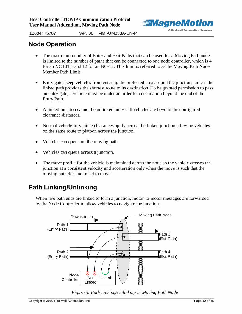
Path Linking/Unlinking
When two path ends are linked to form a junction, motor-to-motor messages are forwarded
by the Node Controller to allow vehicles to navigate the junction.
Figure 3: Path Linking/Unlinking in Moving Path Node
Downstream Moving Path Node
Path 1 (Entry Path)
Path 2 (Entry Path)
Path 4 (Exit Path)
Path 3 (Exit Path)
Node Controller Linked Not
Linked
Host Controller TCP/IP Communication Protocol
User Manual Addendum, Moving Path Node
10004475707 Ver. 00 MMI-UM033A-EN-P
Copyright © 2019 Rockwell Automation, Inc. Page 13 of 45
Host Control of Link (Last Allowed Vehicle ID = 0)
If the host controller links the path with an MP Link Command (0xBF 09 02) that has Last
Allowed Vehicle ID set to ‘0’, the path end remains in the linked state until an MP Unlink
Command (0xBF 09 03) is received. While in the linked state, vehicles are allowed to
navigate the node if the linked path offers a route to the destination for the vehicle.
The host controller must send an MP Unlink Command (0xBF 09 03) to unlink the path. If
the host controller sends the unlink command while the vehicle is navigating the junction, the
junction state changes to linked_unlinked_pending and no additional vehicles are granted
permission to navigate the junction. As soon as the vehicle clears the junction, the path end
state transitions to the unlinked state.
Host Control of Link (last_allowed_vehicle_id = Specific Vehicle ID)
If the host controller links the path with an MP Link Command (0xBF 09 02) that has Last
Allowed Vehicle ID set to a specific vehicle ID, the path end remains in the linked state until
the specified vehicle is granted permission to enter the junction. The path end state
transitions to linked_unlinked_pending as soon as the last allowed vehicle is granted
permission to enter. No other vehicles are allowed permission to navigate the junction after
the last allowed vehicle enters.
Once in the linked_unlinked_pending state, the path transitions to the unlinked state as soon
as all vehicles are clear of the junction. The host controller does not need to send an unlink
command.
NOTE: Additional link commands can be issued to modify the Last Allowed Vehicle ID
for the linked paths but must specify the same Control Path ID and Peer Path ID
used initially to establish the junction.
Entry Gates and Clearance Distances
Configurable entry gate and clearance distances are provided for each path in the Moving
Path node to set vehicle clearances. These clearances are used to protect vehicles from
collisions with the node’s moving mechanisms or other vehicles in the node.
Entry Gates
The entry gate defines a location on the paths that are associated with a node where the
leading edge of the vehicle (including payload) is safely located to avoid collisions with other
vehicles on adjoining paths or with any mechanisms that are related to the node, regardless of
vehicle movement direction. The location of the entry gate is measured from the end of the
motor closest to the node.
Host Controller TCP/IP Communication Protocol
User Manual Addendum, Moving Path Node
10004475707 Ver. 00 MMI-UM033A-EN-P
Copyright © 2019 Rockwell Automation, Inc. Page 14 of 45
Clearance Distances
The clearance distance defines a location on the paths that are associated with a node where
the vehicle’s trailing edge (including payload), regardless of vehicle movement direction, is
safely located to avoid collisions with other vehicles on adjoining paths or with any
mechanisms that are related to the node.
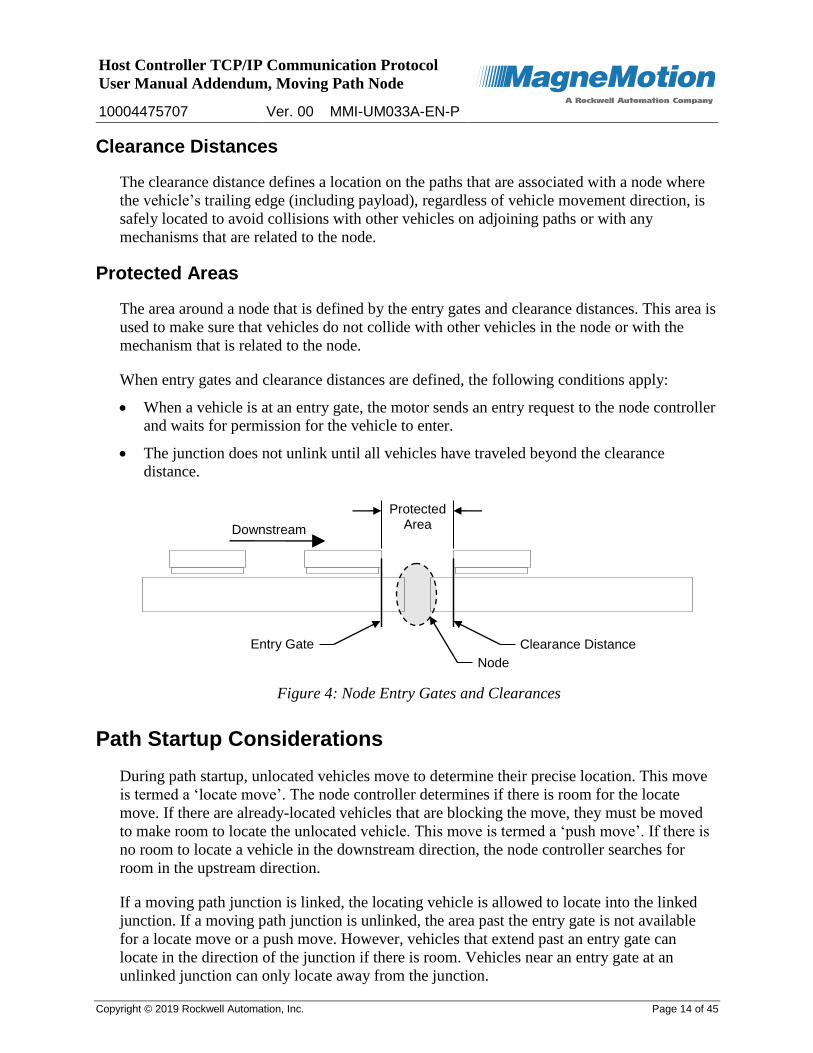
Protected Areas
The area around a node that is defined by the entry gates and clearance distances. This area is
used to make sure that vehicles do not collide with other vehicles in the node or with the
mechanism that is related to the node.
When entry gates and clearance distances are defined, the following conditions apply:
When a vehicle is at an entry gate, the motor sends an entry request to the node controller
and waits for permission for the vehicle to enter.
The junction does not unlink until all vehicles have traveled beyond the clearance
distance.
Figure 4: Node Entry Gates and Clearances
Path Startup Considerations
During path startup, unlocated vehicles move to determine their precise location. This move
is termed a ‘locate move’. The node controller determines if there is room for the locate
move. If there are already-located vehicles that are blocking the move, they must be moved
to make room to locate the unlocated vehicle. This move is termed a ‘push move’. If there is
no room to locate a vehicle in the downstream direction, the node controller searches for
room in the upstream direction.
If a moving path junction is linked, the locating vehicle is allowed to locate into the linked
junction. If a moving path junction is unlinked, the area past the entry gate is not available
for a locate move or a push move. However, vehicles that extend past an entry gate can
locate in the direction of the junction if there is room. Vehicles near an entry gate at an
unlinked junction can only locate away from the junction.
Downstream
Entry Gate Clearance Distance
Node
Protected Area
Host Controller TCP/IP Communication Protocol
User Manual Addendum, Moving Path Node
10004475707 Ver. 00 MMI-UM033A-EN-P
Copyright © 2019 Rockwell Automation, Inc. Page 15 of 45
It is possible that, after an unlocated vehicle that was within the gate area is located, it is still
within the gate area at an unlinked path end. If a vehicle is positioned this way, the path end
status transitions to the unlinked_vehicle_present state and the Device Status field (bits 0-3)
in the Node Status (0xD3) message is set to ‘junction fault’.
The host controller can either move the vehicle clear of the gate, to cause the path end state
to transition to unlinked, or link the junction. Once none of the member path ends of the
Moving Path node are in the unlinked_vehicle_present state, the node device status
transitions to ‘Operational’.
NOTE: A vehicle in the gate area has the potential to interfere with a path being moved to
align it.
Host Controller TCP/IP Communication Protocol
User Manual Addendum, Moving Path Node
10004475707 Ver. 00 MMI-UM033A-EN-P
Copyright © 2019 Rockwell Automation, Inc. Page 16 of 45
Communication Protocol
See the Communications Protocol section in the Appendix of the Host Controller TCP/IP
Communication Protocol User Manual for information on how the TCP/IP protocol is used
between the host controller and the HLC.
Host Controller to HLC Communications
This section describes the commands (see Table 2) that are sent from the host controller to
the HLC as asynchronous requests for the transport system to perform an action. These
requests are handled by the HLC by routing the command to the appropriate node controller
for execution and sending responses to the host controller (listed in Table 3).
Table 2: Host Controller to HLC Commands
Description and Value Use Page
MP Get Path End Status (0xBF 09 01) QuickStick 100 17
MP Link Command (0xBF 09 02) QuickStick 100 19
MP Unlink Command (0xBF 09 03) QuickStick 100 23
Host Controller TCP/IP Communication Protocol
User Manual Addendum, Moving Path Node
10004475707 Ver. 00 MMI-UM033A-EN-P
Copyright © 2019 Rockwell Automation, Inc. Page 17 of 45
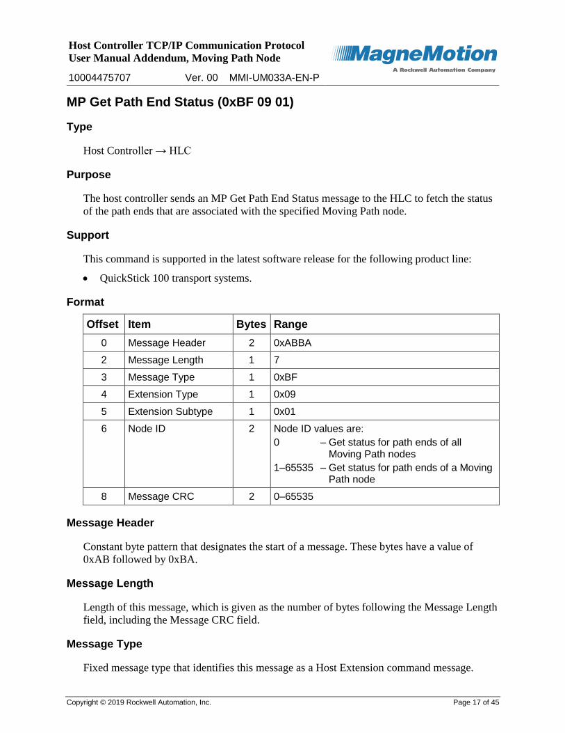
MP Get Path End Status (0xBF 09 01)
Type
Host Controller → HLC
Purpose
The host controller sends an MP Get Path End Status message to the HLC to fetch the status
of the path ends that are associated with the specified Moving Path node.
Support
This command is supported in the latest software release for the following product line:
QuickStick 100 transport systems.
Format
Offset Item Bytes Range
0 Message Header 2 0xABBA
2 Message Length 1 7
3 Message Type 1 0xBF
4 Extension Type 1 0x09
5 Extension Subtype 1 0x01
6 Node ID 2 Node ID values are:
0 – Get status for path ends of all Moving Path nodes
1–65535 – Get status for path ends of a Moving Path node
8 Message CRC 2 0–65535
Message Header
Constant byte pattern that designates the start of a message. These bytes have a value of
0xAB followed by 0xBA.
Message Length
Length of this message, which is given as the number of bytes following the Message Length
field, including the Message CRC field.
Message Type
Fixed message type that identifies this message as a Host Extension command message.
Host Controller TCP/IP Communication Protocol
User Manual Addendum, Moving Path Node
10004475707 Ver. 00 MMI-UM033A-EN-P
Copyright © 2019 Rockwell Automation, Inc. Page 18 of 45
Extension Type
Fixed extension type that identifies this command as a node extension command.
Extension Subtype
Fixed extension subtype that identifies this command as an MP Get Path End Status
extension command.
Node ID
ID of the Moving Path node for which path end status is being requested.
0 The HLC gets path end status for all Moving Path nodes. An MP Path End Status Report (0xDF 09 01) message is returned for each path end with its associated Node ID and a Command Status of Command Accepted. If no Moving Path nodes exist, the HLC rejects the command and an MP Path End Status Report (0xDF 09 01) message is returned with a Node ID of 0 and a Command Status of No record available.
1–65535 The HLC gets path end status for only the Moving Path node with a matching Node ID. If the specified Moving Path node does not exist, an MP Path End Status Report (0xDF 09 01) message is returned with the failing Node ID and a Command Status of No record available indicating that no such Moving Path node exists in the transport system.
If the HLC rejects an MP Get Path End Status command, the Node ID and the failure status
are included in the MP Path End Status Report (0xDF 09 01) message.
Message CRC
A check value on the entire message (excluding the CRC) to verify integrity.
Response
After receiving the command and verifying command parameters, the HLC sends one or
more MP Path End Status Report (0xDF 09 01) messages for each path end that is a member
of the specified Moving Path nodes.

Host Controller TCP/IP Communication Protocol
User Manual Addendum, Moving Path Node
10004475707 Ver. 00 MMI-UM033A-EN-P
Copyright © 2019 Rockwell Automation, Inc. Page 19 of 45
MP Link Command (0xBF 09 02)
Type
Host Controller → HLC
Purpose
The host controller sends an MP Link Command message to the HLC when the Control and
Peer Paths are aligned. This message notifies the HLC that the path ends are aligned and can
be ‘linked’ to allow vehicles to navigate the path junction.
The initial link command, sent to form a junction between two unlinked path ends,
establishes the Control Path. Subsequent link commands can be issued to modify the Last
Allowed Vehicle ID but must specify the same Control and Peer Path IDs used initially to
establish the junction.
These messages can be sent asynchronously or in response to a previous MP Alignment
Request (0xDF 09 02) message.
Support
This command is supported in the latest software release for the following product line:
QuickStick 100 transport systems.
Format
Offset Item Bytes Range
0 Message Header 2 0xABBA
2 Message Length 1 19
3 Message Type 1 0xBF
4 Extension Type 1 0x09
5 Extension Subtype 1 0x02
6 Node ID 2 1–65535
8 Control Path ID 2 1–65535
10 Peer Path ID 2 1–65535
12 Last Allowed Vehicle ID
2 Last Allowed Vehicle ID values are:
0 – Path junction remains linked until explicitly unlinked
1–65535 – Path junction unlinked when this vehicle clears it
14 Alignment Request Count
2 1–65535
Host Controller TCP/IP Communication Protocol
User Manual Addendum, Moving Path Node
10004475707 Ver. 00 MMI-UM033A-EN-P
Copyright © 2019 Rockwell Automation, Inc. Page 20 of 45
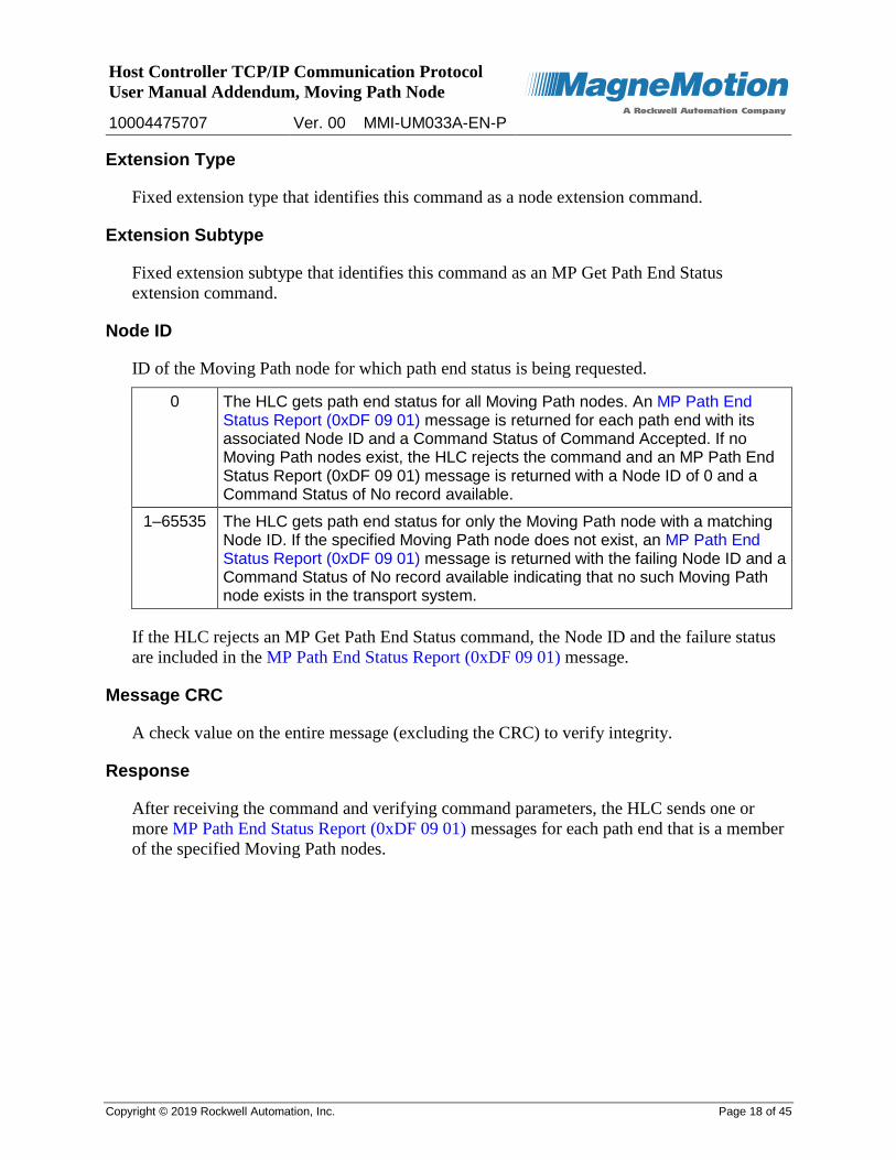
Offset Item Bytes Range
16 Host Command Count 4 0x–0xFFFFFFFF
20 Message CRC 2 0–65535
Message Header
Constant byte pattern that designates the start of a message. These bytes have a value of
0xAB followed by 0xBA.
Message Length
Length of this message, which is given as the number of bytes following the Message Length
field, including the Message CRC field.
Message Type
Fixed message type that identifies this message as a Host Extension command message.
Extension Type
Fixed extension type that identifies this command as a node extension command.
Extension Subtype
Fixed extension subtype that identifies this command as an MP Link Command extension
command.
Node ID
The ID of the Moving Path node that this link command operates on. The ID must reference
a node that exists in the transport system.
Control Path ID
The ID of the Control Path end to link to the specified Peer Path end to form a path junction.
The ID must reference a path that exists in the transport system.
Peer Path ID
The ID of the Peer Path end to link to the specified Control Path end to form a path junction.
The ID must reference a path that exists in the transport system.
NOTE: New path junctions transition to the linked state.
Host Controller TCP/IP Communication Protocol
User Manual Addendum, Moving Path Node
10004475707 Ver. 00 MMI-UM033A-EN-P
Copyright © 2019 Rockwell Automation, Inc. Page 21 of 45
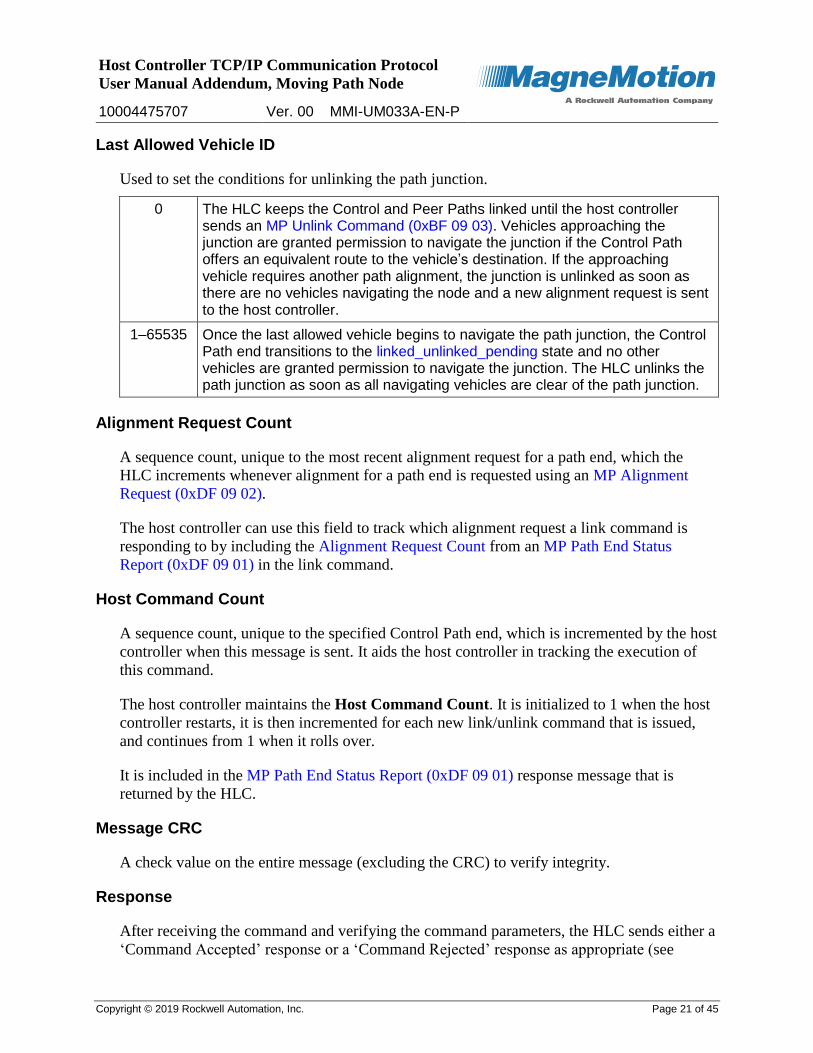
Last Allowed Vehicle ID
Used to set the conditions for unlinking the path junction.
0 The HLC keeps the Control and Peer Paths linked until the host controller sends an MP Unlink Command (0xBF 09 03). Vehicles approaching the junction are granted permission to navigate the junction if the Control Path offers an equivalent route to the vehicle’s destination. If the approaching vehicle requires another path alignment, the junction is unlinked as soon as there are no vehicles navigating the node and a new alignment request is sent to the host controller.
1–65535 Once the last allowed vehicle begins to navigate the path junction, the Control Path end transitions to the linked_unlinked_pending state and no other vehicles are granted permission to navigate the junction. The HLC unlinks the path junction as soon as all navigating vehicles are clear of the path junction.
Alignment Request Count
A sequence count, unique to the most recent alignment request for a path end, which the
HLC increments whenever alignment for a path end is requested using an MP Alignment
Request (0xDF 09 02).
The host controller can use this field to track which alignment request a link command is
responding to by including the Alignment Request Count from an MP Path End Status
Report (0xDF 09 01) in the link command.
Host Command Count
A sequence count, unique to the specified Control Path end, which is incremented by the host
controller when this message is sent. It aids the host controller in tracking the execution of
this command.
The host controller maintains the Host Command Count. It is initialized to 1 when the host
controller restarts, it is then incremented for each new link/unlink command that is issued,
and continues from 1 when it rolls over.
It is included in the MP Path End Status Report (0xDF 09 01) response message that is
returned by the HLC.
Message CRC
A check value on the entire message (excluding the CRC) to verify integrity.
Response
After receiving the command and verifying the command parameters, the HLC sends either a
‘Command Accepted’ response or a ‘Command Rejected’ response as appropriate (see
Host Controller TCP/IP Communication Protocol
User Manual Addendum, Moving Path Node
10004475707 Ver. 00 MMI-UM033A-EN-P
Copyright © 2019 Rockwell Automation, Inc. Page 22 of 45
Command Status (0xD0)). If the command is accepted, the HLC handles linking the
specified path junctions for the selected Moving Path node.
On completion of the command, the HLC sends a ‘Command Complete’ or a ‘Command
Failed’ response. If the command failed, the response identifies the reason for failure.
If the HLC is configured to report path end status changes asynchronously, the HLC
responds with one or more MP Path End Status Report (0xDF 09 01) messages reflecting
changes resulting from executing this link command.
Host Controller TCP/IP Communication Protocol
User Manual Addendum, Moving Path Node
10004475707 Ver. 00 MMI-UM033A-EN-P
Copyright © 2019 Rockwell Automation, Inc. Page 23 of 45
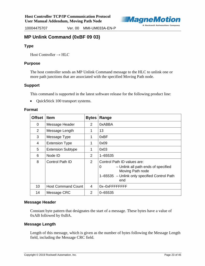
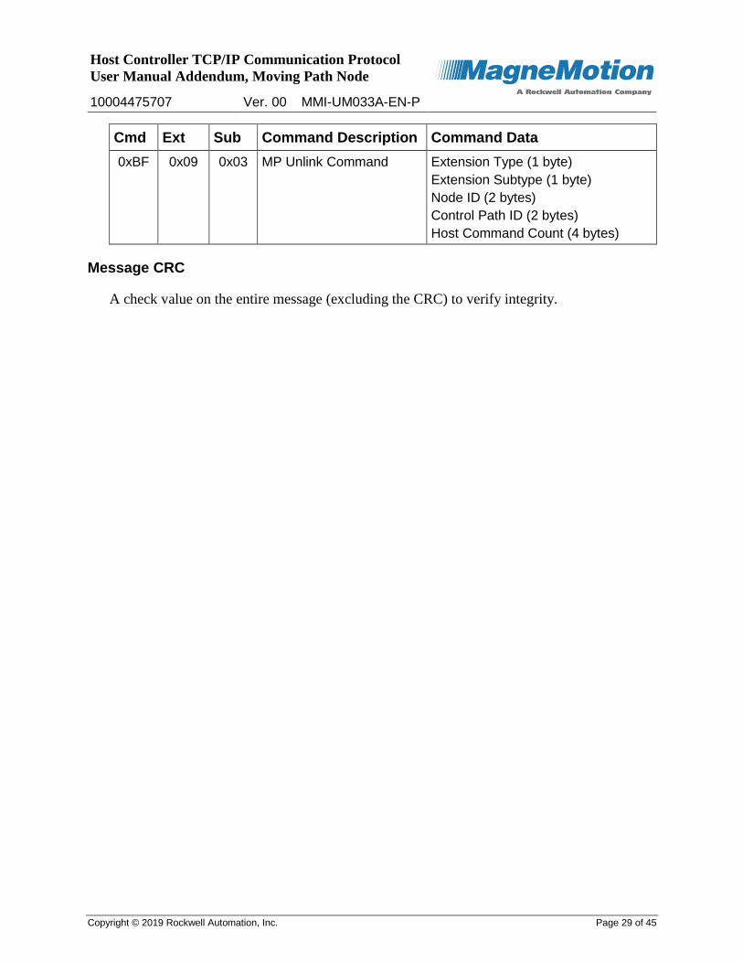
MP Unlink Command (0xBF 09 03)
Type
Host Controller → HLC
Purpose
The host controller sends an MP Unlink Command message to the HLC to unlink one or
more path junctions that are associated with the specified Moving Path node.
Support
This command is supported in the latest software release for the following product line:
QuickStick 100 transport systems.
Format
Offset Item Bytes Range
0 Message Header 2 0xABBA
2 Message Length 1 13
3 Message Type 1 0xBF
4 Extension Type 1 0x09
5 Extension Subtype 1 0x03
6 Node ID 2 1–65535
8 Control Path ID 2 Control Path ID values are:
0 – Unlink all path ends of specified Moving Path node
1–65535 – Unlink only specified Control Path end
10 Host Command Count 4 0x–0xFFFFFFFF
14 Message CRC 2 0–65535
Message Header
Constant byte pattern that designates the start of a message. These bytes have a value of
0xAB followed by 0xBA.
Message Length
Length of this message, which is given as the number of bytes following the Message Length
field, including the Message CRC field.
Host Controller TCP/IP Communication Protocol
User Manual Addendum, Moving Path Node
10004475707 Ver. 00 MMI-UM033A-EN-P
Copyright © 2019 Rockwell Automation, Inc. Page 24 of 45
Message Type
Fixed message type that identifies this message as a Host Extension command message.
Extension Type
Fixed extension type that identifies this command as a node extension command.
Extension Subtype
Fixed extension subtype that identifies this command as an MP Unlink Command extension
command.
Node ID
The ID of the Moving Path node that this unlink command operates on. The ID must
reference a node that exists in the transport system.
Control Path ID
The ID of one or more path ends to unlink from path junctions that are associated with the
specified Moving Path node. The ID must reference a path that exists in the transport system.
0 All member path ends are unlinked for the specified Moving Path node.
1–65535 Only the specified Control Path end is unlinked. Additionally, the Control Path ID specified must be the same Control Path that was used initially to establish the junction.
If a vehicle is navigating a path junction, the path junction transitions to the
linked_unlinked_pending state; otherwise, the path junction transitions to the unlinked state.
See MP Path End States on page 39 for detailed descriptions of the path end states.
Host Command Count
A sequence count, unique to the specified Control Path end, which the host controller
increments when this message is sent. It aids the host controller in tracking the execution of
this command.
The host controller maintains the Host Command Count. It is initialized to 1 when the host
controller restarts, it is then incremented for each new link/unlink command that is issued,
and continues from 1 when it rolls over.
It is included in the MP Path End Status Report (0xDF 09 01) response message that is
returned by the HLC.
Host Controller TCP/IP Communication Protocol
User Manual Addendum, Moving Path Node
10004475707 Ver. 00 MMI-UM033A-EN-P
Copyright © 2019 Rockwell Automation, Inc. Page 25 of 45
Message CRC
A check value on the entire message (excluding the CRC) to verify integrity.
Response
After receiving the command and verifying the command parameters, the HLC sends either a
‘Command Accepted’ response or a ‘Command Rejected’ response as appropriate (see
Command Status (0xD0)). If the command is accepted, the HLC handles unlinking the
specified path junctions for the selected Moving Path node.
On completion of the command, the HLC sends a ‘Command Complete’ (path junction
transitions to the linked_unlinked_pending state) or a ‘Command Failed’ response. If the
command failed, the response identifies the reason for failure.
If the HLC is configured to report path end status changes asynchronously, the HLC
responds with one or more MP Path End Status Report (0xDF 09 01) messages reflecting
changes resulting from executing this link command.
Host Controller TCP/IP Communication Protocol
User Manual Addendum, Moving Path Node
10004475707 Ver. 00 MMI-UM033A-EN-P
Copyright © 2019 Rockwell Automation, Inc. Page 26 of 45
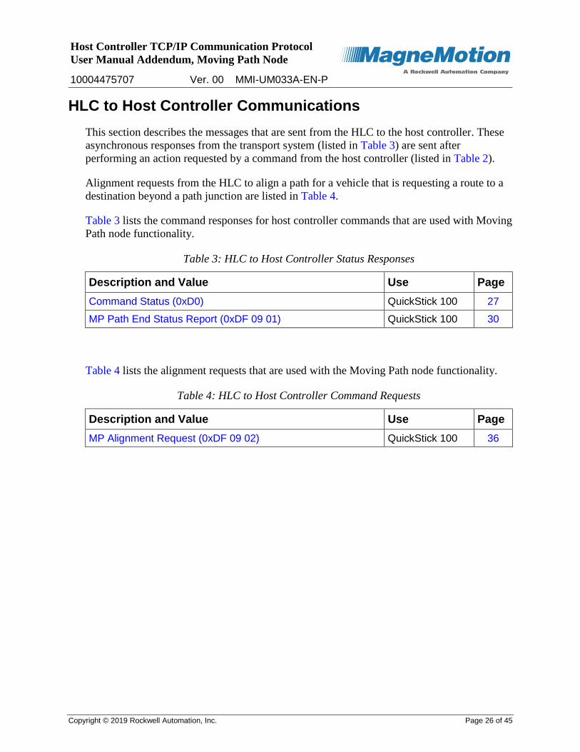
HLC to Host Controller Communications
This section describes the messages that are sent from the HLC to the host controller. These
asynchronous responses from the transport system (listed in Table 3) are sent after
performing an action requested by a command from the host controller (listed in Table 2).
Alignment requests from the HLC to align a path for a vehicle that is requesting a route to a
destination beyond a path junction are listed in Table 4.
Table 3 lists the command responses for host controller commands that are used with Moving
Path node functionality.
Table 3: HLC to Host Controller Status Responses
Description and Value Use Page
Command Status (0xD0) QuickStick 100 27
MP Path End Status Report (0xDF 09 01) QuickStick 100 30
Table 4 lists the alignment requests that are used with the Moving Path node functionality.
Table 4: HLC to Host Controller Command Requests
Description and Value Use Page
MP Alignment Request (0xDF 09 02) QuickStick 100 36

Host Controller TCP/IP Communication Protocol
User Manual Addendum, Moving Path Node
10004475707 Ver. 00 MMI-UM033A-EN-P
Copyright © 2019 Rockwell Automation, Inc. Page 27 of 45
Command Status (0xD0)
Type
HLC → Host Controller
Purpose
Acknowledges the reception or rejection of a command, signals command execution failure,
or signals command completion to the host controller.
NOTE: This response is sent as an asynchronous message with the appropriate command
type when certain commands complete or fail.
Support
This response is supported in the latest software release for the following product line:
QuickStick 100 transport systems.
Format
Offset Item Bytes Range
0 Message Header 2 0xABBA
2 Message Length 1 varies
3 Message Type 1 0xD0
4 Command 1 0xB0–0xBC, 0xBF
5 Command Status 1 0x00–0x80
6 Command Data Detail Varies Varies
Varies Message CRC 2 0–65535
Message Header
Constant byte pattern that designates the start of a message. These bytes have a value of
0xAB followed by 0xBA.
Message Length
Length of this message, which is given as the number of bytes following the Message Length
field, including the Message CRC field.
Message Type
Fixed message type that identifies this message as a Command Status response message.

Host Controller TCP/IP Communication Protocol
User Manual Addendum, Moving Path Node
10004475707 Ver. 00 MMI-UM033A-EN-P
Copyright © 2019 Rockwell Automation, Inc. Page 28 of 45
Command
Fixed message type that identifies the command that this Command Status message
acknowledges.
Cmd Ext Sub Command Command Status Values
0xBF 0x09 0x02 MP Link Command 0x00, 0x03, 0x09, 0x0C, 0x0D, 0x10, 0x19, 0x20, 0x41, 0x42, 0x80
0xBF 0x09 0x03 MP Unlink Command 0x00, 0x03, 0x0C, 0x19, 0x20, 0x41, 0x42, 0x80
Command Status
The status of the command that this Command Status message acknowledges.
Value Status Description
0x00 Command Accepted
0x03 Command Rejected – Invalid Path ID
0x09 Command Rejected – Startup sequence already started
0x0C Command Rejected – Initialization not complete
0x0D Command Rejected – Reset active
0x10 Command Rejected – Programming active
0x19 Command Rejected – Invalid Node ID
0x20 Command Rejected – Invalid node type
0x41 Command Failed – Unable to complete
0x42 Command Failed – Timed out
0x80 Command Completed Successfully
Command Data Detail
Variable amount of data that provides the details of the command that is specified in the
Command field.
Cmd Ext Sub Command Description Command Data
0xBF 0x09 0x02 MP Link Command Extension Type (1 byte)
Extension Subtype (1 byte)
Node ID (2 bytes)
Control Path ID (2 bytes)
Peer Path ID (2 bytes)
Last Allowed Vehicle ID (2 bytes)
Alignment Request Count (2 bytes)
Host Command Count (4 bytes)
Host Controller TCP/IP Communication Protocol
User Manual Addendum, Moving Path Node
10004475707 Ver. 00 MMI-UM033A-EN-P
Copyright © 2019 Rockwell Automation, Inc. Page 29 of 45
Cmd Ext Sub Command Description Command Data
0xBF 0x09 0x03 MP Unlink Command Extension Type (1 byte)
Extension Subtype (1 byte)
Node ID (2 bytes)
Control Path ID (2 bytes)
Host Command Count (4 bytes)
Message CRC
A check value on the entire message (excluding the CRC) to verify integrity.
Host Controller TCP/IP Communication Protocol
User Manual Addendum, Moving Path Node
10004475707 Ver. 00 MMI-UM033A-EN-P
Copyright © 2019 Rockwell Automation, Inc. Page 30 of 45
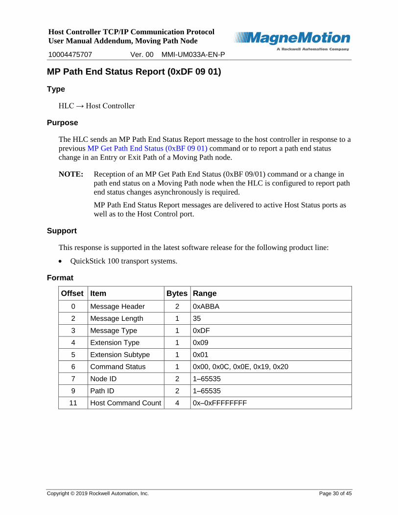
MP Path End Status Report (0xDF 09 01)
Type
HLC → Host Controller
Purpose
The HLC sends an MP Path End Status Report message to the host controller in response to a
previous MP Get Path End Status (0xBF 09 01) command or to report a path end status
change in an Entry or Exit Path of a Moving Path node.
NOTE: Reception of an MP Get Path End Status (0xBF 09/01) command or a change in
path end status on a Moving Path node when the HLC is configured to report path
end status changes asynchronously is required.
MP Path End Status Report messages are delivered to active Host Status ports as
well as to the Host Control port.
Support
This response is supported in the latest software release for the following product line:
QuickStick 100 transport systems.
Format
Offset Item Bytes Range
0 Message Header 2 0xABBA
2 Message Length 1 35
3 Message Type 1 0xDF
4 Extension Type 1 0x09
5 Extension Subtype 1 0x01
6 Command Status 1 0x00, 0x0C, 0x0E, 0x19, 0x20
7 Node ID 2 1–65535
9 Path ID 2 1–65535
11 Host Command Count 4 0x–0xFFFFFFFF

Host Controller TCP/IP Communication Protocol
User Manual Addendum, Moving Path Node
10004475707 Ver. 00 MMI-UM033A-EN-P
Copyright © 2019 Rockwell Automation, Inc. Page 31 of 45
Offset Item Bytes Range
15 Path End State 1 Path End State values are:
1 – unlinked
2 – linked_unlink_pending
3 – unlinked_alignment_requested
4 – linked
5 – linked_comm_loss
6 – linked_peer
7 – unlinked_vehicle_present
16 Path End Role 1 Path End Role values are:
1 – Unlinked path
2 – Control Path
3 – Peer Path
17 Path End Type 1 Path End Type values are:
1 – Fixed Path end (configured as specific-route path)
2 – Moving Path end (configured as equivalent-route path)
18 Peer Node ID 2 0–65535
20 Requested Path ID 2 0–65535
22 Linked Path ID 2 0–65535
24 Last Allowed Vehicle ID
2 Last Allowed Vehicle ID values are:
0 – Allow vehicles to navigate if the junction is a valid route to the destination
1–65535 – ID of last vehicle allowed to navigate junction
26 Requesting Vehicle ID 2 0–65535
28 Last Entered Vehicle ID
2 Last Entered Vehicle ID values are:
0 – No active vehicle
1–65535 – ID of vehicle requesting entry or ID of the last vehicle through the entry gate
30 Owner Vehicle ID 2 Owner Vehicle ID values are:
0 – No vehicle owns the junction
1–65535 – ID of vehicle that owns the junction
32 Last Exited Vehicle ID 2 Last Exited Vehicle ID values are:
0 – No vehicle has cleared the junction since it was linked
1–65535 – ID of the most recent vehicle to clear the junction
Host Controller TCP/IP Communication Protocol
User Manual Addendum, Moving Path Node
10004475707 Ver. 00 MMI-UM033A-EN-P
Copyright © 2019 Rockwell Automation, Inc. Page 32 of 45
Offset Item Bytes Range
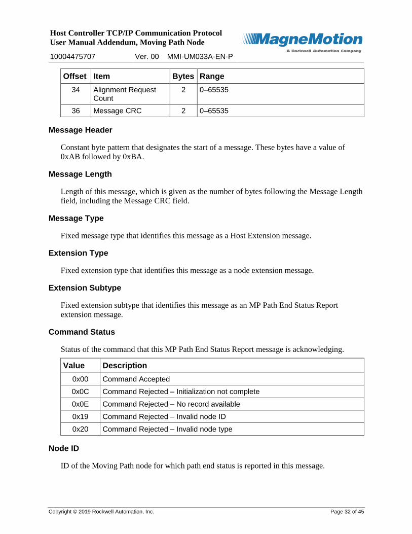
34 Alignment Request Count
2 0–65535
36 Message CRC 2 0–65535
Message Header
Constant byte pattern that designates the start of a message. These bytes have a value of
0xAB followed by 0xBA.
Message Length
Length of this message, which is given as the number of bytes following the Message Length
field, including the Message CRC field.
Message Type
Fixed message type that identifies this message as a Host Extension message.
Extension Type
Fixed extension type that identifies this message as a node extension message.
Extension Subtype
Fixed extension subtype that identifies this message as an MP Path End Status Report
extension message.
Command Status
Status of the command that this MP Path End Status Report message is acknowledging.
Value Description
0x00 Command Accepted
0x0C Command Rejected – Initialization not complete
0x0E Command Rejected – No record available
0x19 Command Rejected – Invalid node ID
0x20 Command Rejected – Invalid node type
Node ID
ID of the Moving Path node for which path end status is reported in this message.

Host Controller TCP/IP Communication Protocol
User Manual Addendum, Moving Path Node
10004475707 Ver. 00 MMI-UM033A-EN-P
Copyright © 2019 Rockwell Automation, Inc. Page 33 of 45
Path ID
The ID of the path end for which status is being reported.
Host Command Count
A sequence count, unique to the specified path end, last received in a link or unlink
command. The host controller maintains the Host Command Count.
Path End State
The state for this path end. See MP Path End States on page 39 for detailed descriptions of
the path end states.
Path End Role
The role for this path end.
1 Unlinked Path – Path is not linked to another path.
2 Control Path – Path specified in an MP Link command to link to a Peer Path.
3 Peer Path – Path specified in an MP Link command to link from a Control Path.
Path End Type
The type of path end.
1 Fixed Path End – A path end that is configured as a specific-route path.
2 Moving Path End – A path end that is configured as an equivalent-route path.
Peer Node ID
The ID of the node at the far end of this Moving Path node member path.
0 There is no Moving Path node at the far end of a moving path or if the member path is a fixed path (that is, configured as a specific-route path).
1–65535 The ID of the node at the far end of a moving path if the member path is a moving path (that is, configured as an equivalent-route path).
Requested Path ID
The Requested Path ID field is written when a path end transitions to the
unlinked_alignment_requested state. This is a signal to the host controller that a vehicle is
requesting permission to navigate a Moving Path node as follows:
If the Requested Path ID field is zero, the path end is not linked and the host controller
can align any equivalent moving path to provide a route to the vehicle’s destination.
Host Controller TCP/IP Communication Protocol
User Manual Addendum, Moving Path Node
10004475707 Ver. 00 MMI-UM033A-EN-P
Copyright © 2019 Rockwell Automation, Inc. Page 34 of 45
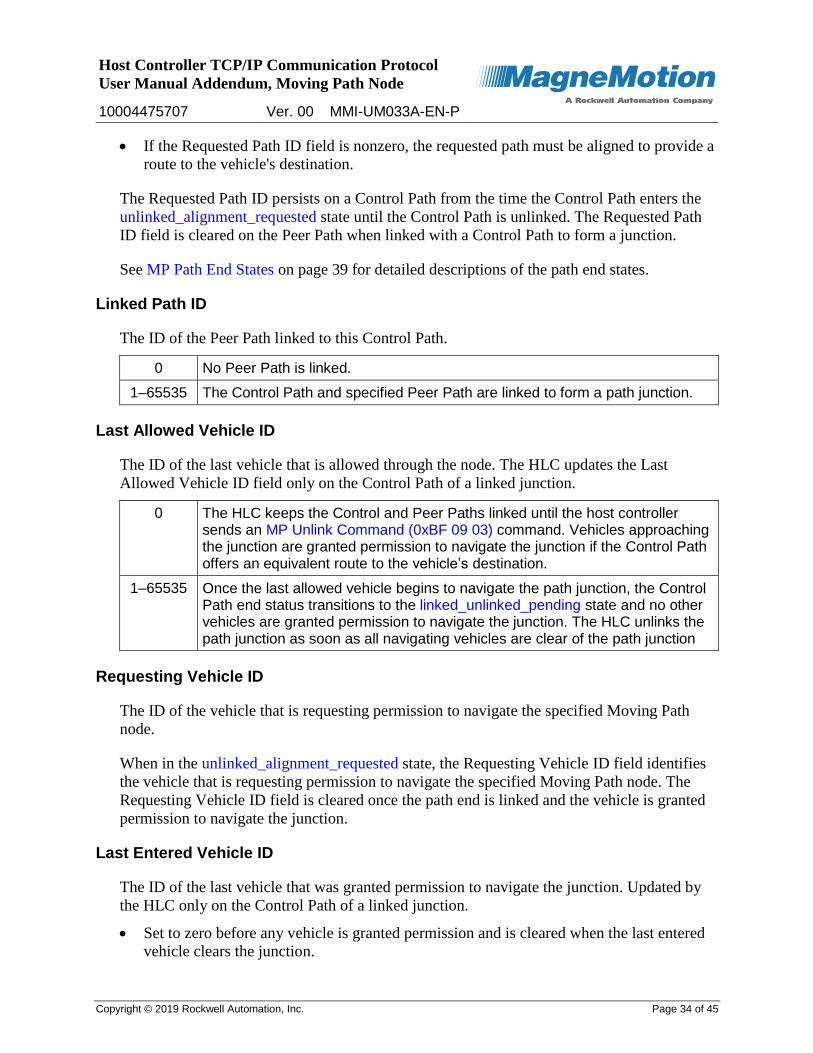
If the Requested Path ID field is nonzero, the requested path must be aligned to provide a
route to the vehicle's destination.
The Requested Path ID persists on a Control Path from the time the Control Path enters the
unlinked_alignment_requested state until the Control Path is unlinked. The Requested Path
ID field is cleared on the Peer Path when linked with a Control Path to form a junction.
See MP Path End States on page 39 for detailed descriptions of the path end states.
Linked Path ID
The ID of the Peer Path linked to this Control Path.
0 No Peer Path is linked.
1–65535 The Control Path and specified Peer Path are linked to form a path junction.
Last Allowed Vehicle ID
The ID of the last vehicle that is allowed through the node. The HLC updates the Last
Allowed Vehicle ID field only on the Control Path of a linked junction.
0 The HLC keeps the Control and Peer Paths linked until the host controller sends an MP Unlink Command (0xBF 09 03) command. Vehicles approaching the junction are granted permission to navigate the junction if the Control Path offers an equivalent route to the vehicle’s destination.
1–65535 Once the last allowed vehicle begins to navigate the path junction, the Control Path end status transitions to the linked_unlinked_pending state and no other vehicles are granted permission to navigate the junction. The HLC unlinks the path junction as soon as all navigating vehicles are clear of the path junction
Requesting Vehicle ID
The ID of the vehicle that is requesting permission to navigate the specified Moving Path
node.
When in the unlinked_alignment_requested state, the Requesting Vehicle ID field identifies
the vehicle that is requesting permission to navigate the specified Moving Path node. The
Requesting Vehicle ID field is cleared once the path end is linked and the vehicle is granted
permission to navigate the junction.
Last Entered Vehicle ID
The ID of the last vehicle that was granted permission to navigate the junction. Updated by
the HLC only on the Control Path of a linked junction.
Set to zero before any vehicle is granted permission and is cleared when the last entered
vehicle clears the junction.
Host Controller TCP/IP Communication Protocol
User Manual Addendum, Moving Path Node
10004475707 Ver. 00 MMI-UM033A-EN-P
Copyright © 2019 Rockwell Automation, Inc. Page 35 of 45
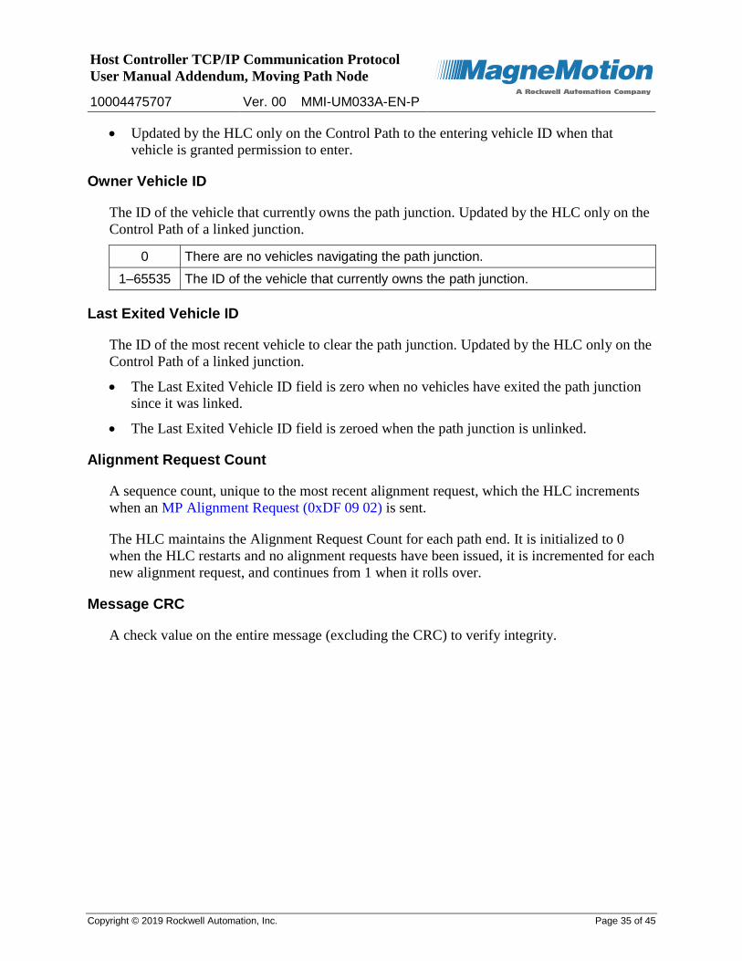
Updated by the HLC only on the Control Path to the entering vehicle ID when that
vehicle is granted permission to enter.
Owner Vehicle ID
The ID of the vehicle that currently owns the path junction. Updated by the HLC only on the
Control Path of a linked junction.
0 There are no vehicles navigating the path junction.
1–65535 The ID of the vehicle that currently owns the path junction.
Last Exited Vehicle ID
The ID of the most recent vehicle to clear the path junction. Updated by the HLC only on the
Control Path of a linked junction.
The Last Exited Vehicle ID field is zero when no vehicles have exited the path junction
since it was linked.
The Last Exited Vehicle ID field is zeroed when the path junction is unlinked.
Alignment Request Count
A sequence count, unique to the most recent alignment request, which the HLC increments
when an MP Alignment Request (0xDF 09 02) is sent.
The HLC maintains the Alignment Request Count for each path end. It is initialized to 0
when the HLC restarts and no alignment requests have been issued, it is incremented for each
new alignment request, and continues from 1 when it rolls over.
Message CRC
A check value on the entire message (excluding the CRC) to verify integrity.
Host Controller TCP/IP Communication Protocol
User Manual Addendum, Moving Path Node
10004475707 Ver. 00 MMI-UM033A-EN-P
Copyright © 2019 Rockwell Automation, Inc. Page 36 of 45
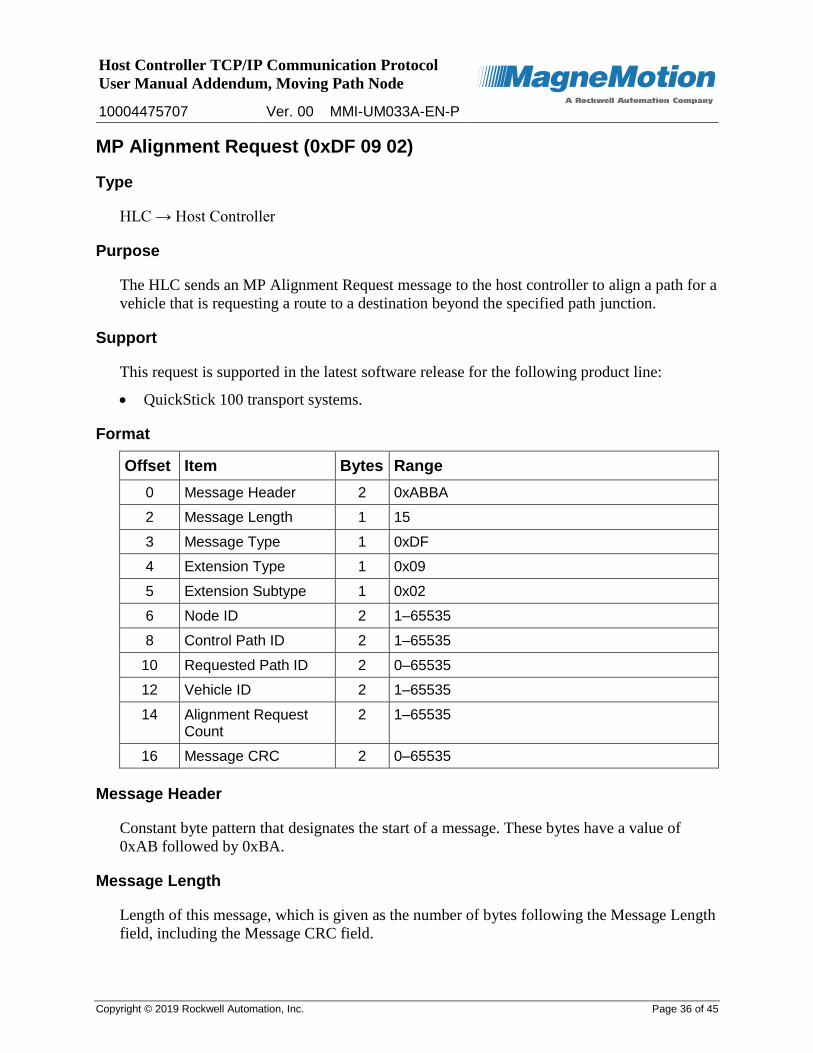
MP Alignment Request (0xDF 09 02)
Type
HLC → Host Controller
Purpose
The HLC sends an MP Alignment Request message to the host controller to align a path for a
vehicle that is requesting a route to a destination beyond the specified path junction.
Support
This request is supported in the latest software release for the following product line:
QuickStick 100 transport systems.
Format
Offset Item Bytes Range
0 Message Header 2 0xABBA
2 Message Length 1 15
3 Message Type 1 0xDF
4 Extension Type 1 0x09
5 Extension Subtype 1 0x02
6 Node ID 2 1–65535
8 Control Path ID 2 1–65535
10 Requested Path ID 2 0–65535
12 Vehicle ID 2 1–65535
14 Alignment Request Count
2 1–65535
16 Message CRC 2 0–65535
Message Header
Constant byte pattern that designates the start of a message. These bytes have a value of
0xAB followed by 0xBA.
Message Length
Length of this message, which is given as the number of bytes following the Message Length
field, including the Message CRC field.

Host Controller TCP/IP Communication Protocol
User Manual Addendum, Moving Path Node
10004475707 Ver. 00 MMI-UM033A-EN-P
Copyright © 2019 Rockwell Automation, Inc. Page 37 of 45
Message Type
Fixed message type that identifies this message as a Host Extension message.
Extension Type
Fixed extension type that identifies this message as a node extension message.
Extension Subtype
Fixed extension subtype that identifies this message as an MP Alignment Request extension
message.
Node ID
The ID of the Moving Path node for which this path end alignment request applies.
Control Path ID
The ID of the path where a vehicle is requesting permission to navigate the specified Moving
Path node.
Requested Path ID
The Requested Path ID field is a signal to the host controller that a vehicle is requesting
permission to navigate a Moving Path node as follows:
If the Requested Path ID field is zero, the host controller can align any path that offers an
equivalent path route to the vehicle’s destination.
If the Requested Path ID field is nonzero, the host controller must align the requested
path to the Control Path to satisfy the vehicle’s route to its destination.
The Requested Path ID persists on a Control Path from the time the Control Path enters the
unlinked_alignment_requested state until the Control Path is unlinked. The Requested Path
ID field is cleared on the Peer Path when linked with a Control Path to form a junction.
See MP Path End States on page 39 for detailed descriptions of the path end states.
Vehicle ID
The ID of the vehicle to navigate the path junction once it is properly aligned.
Alignment Request Count
A sequence count, unique to the most recent alignment request, which the HLC increments
when an MP Alignment Request is sent. The HLC maintains the Alignment Request Count.

Host Controller TCP/IP Communication Protocol
User Manual Addendum, Moving Path Node
10004475707 Ver. 00 MMI-UM033A-EN-P
Copyright © 2019 Rockwell Automation, Inc. Page 38 of 45
Message CRC
A check value on the entire message (excluding the CRC) to verify integrity.
Response
The host controller responds with an MP Link Command (0xBF 09 02) once the control and
requested path ends are properly aligned.
Host Controller TCP/IP Communication Protocol
User Manual Addendum, Moving Path Node
10004475707 Ver. 00 MMI-UM033A-EN-P
Copyright © 2019 Rockwell Automation, Inc. Page 39 of 45
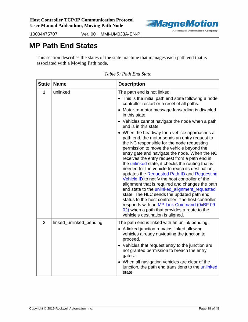
MP Path End States
This section describes the states of the state machine that manages each path end that is
associated with a Moving Path node.
Table 5: Path End State
State Name Description
1 unlinked The path end is not linked.
This is the initial path end state following a node controller restart or a reset of all paths.
Motor-to-motor message forwarding is disabled in this state.
Vehicles cannot navigate the node when a path end is in this state.
When the headway for a vehicle approaches a path end, the motor sends an entry request to the NC responsible for the node requesting permission to move the vehicle beyond the entry gate and navigate the node. When the NC receives the entry request from a path end in the unlinked state, it checks the routing that is needed for the vehicle to reach its destination, updates the Requested Path ID and Requesting Vehicle ID to notify the host controller of the alignment that is required and changes the path end state to the unlinked_alignment_requested state. The HLC sends the updated path end status to the host controller. The host controller responds with an MP Link Command (0xBF 09 02) when a path that provides a route to the vehicle’s destination is aligned.
2 linked_unlinked_pending The path end is linked with an unlink pending.
A linked junction remains linked allowing vehicles already navigating the junction to proceed.
Vehicles that request entry to the junction are not granted permission to breach the entry gates.
When all navigating vehicles are clear of the junction, the path end transitions to the unlinked state.
Host Controller TCP/IP Communication Protocol
User Manual Addendum, Moving Path Node
10004475707 Ver. 00 MMI-UM033A-EN-P
Copyright © 2019 Rockwell Automation, Inc. Page 40 of 45
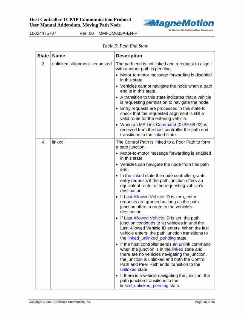
Table 5: Path End State
State Name Description
3 unlinked_alignment_requested The path end is not linked and a request to align it with another path is pending.
Motor-to-motor message forwarding is disabled in this state.
Vehicles cannot navigate the node when a path end is in this state.
A transition to this state indicates that a vehicle is requesting permission to navigate the node.
Entry requests are processed in this state to check that the requested alignment is still a valid route for the entering vehicle.
When an MP Link Command (0xBF 09 02) is received from the host controller the path end transitions to the linked state.
4 linked The Control Path is linked to a Peer Path to form a path junction.
Motor-to-motor message forwarding is enabled in this state.
Vehicles can navigate the node from this path end.
In the linked state the node controller grants entry requests if the path junction offers an equivalent route to the requesting vehicle’s destination.
If Last Allowed Vehicle ID is zero, entry requests are granted as long as the path junction offers a route to the vehicle’s destination.
If Last Allowed Vehicle ID is set, the path junction continues to let vehicles in until the Last Allowed Vehicle ID enters. When the last vehicle enters, the path junction transitions to the linked_unlinked_pending state.
If the host controller sends an unlink command when the junction is in the linked state and there are no vehicles navigating the junction, the junction is unlinked and both the Control Path and Peer Path ends transition to the unlinked state.
If there is a vehicle navigating the junction, the path junction transitions to the linked_unlinked_pending state.
Host Controller TCP/IP Communication Protocol
User Manual Addendum, Moving Path Node
10004475707 Ver. 00 MMI-UM033A-EN-P
Copyright © 2019 Rockwell Automation, Inc. Page 41 of 45
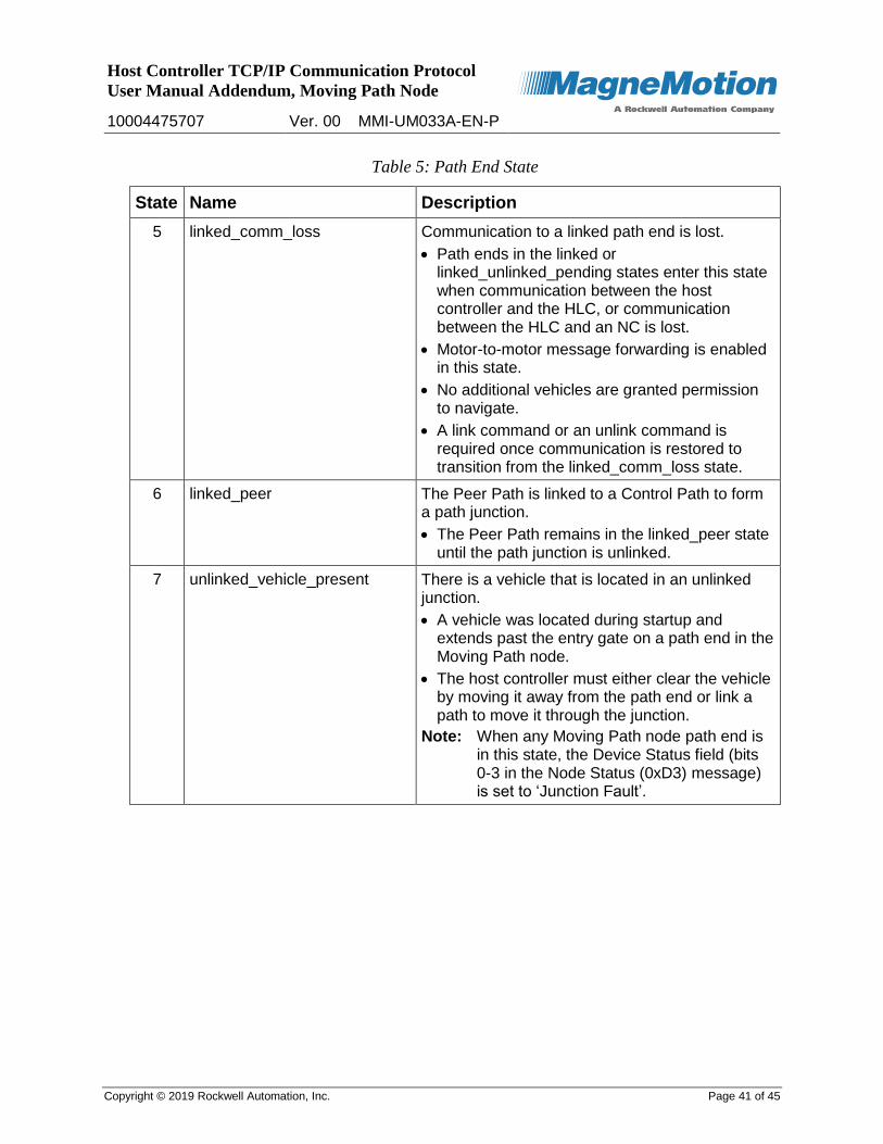
Table 5: Path End State
State Name Description
5 linked_comm_loss Communication to a linked path end is lost.
Path ends in the linked or linked_unlinked_pending states enter this state when communication between the host controller and the HLC, or communication between the HLC and an NC is lost.
Motor-to-motor message forwarding is enabled in this state.
No additional vehicles are granted permission to navigate.
A link command or an unlink command is required once communication is restored to transition from the linked_comm_loss state.
6 linked_peer The Peer Path is linked to a Control Path to form a path junction.
The Peer Path remains in the linked_peer state until the path junction is unlinked.
7 unlinked_vehicle_present There is a vehicle that is located in an unlinked junction.
A vehicle was located during startup and extends past the entry gate on a path end in the Moving Path node.
The host controller must either clear the vehicle by moving it away from the path end or link a path to move it through the junction.
Note: When any Moving Path node path end is in this state, the Device Status field (bits 0-3 in the Node Status (0xD3) message) is set to ‘Junction Fault’.
Host Controller TCP/IP Communication Protocol
User Manual Addendum, Moving Path Node
10004475707 Ver. 00 MMI-UM033A-EN-P
Copyright © 2019 Rockwell Automation, Inc. Page 42 of 45
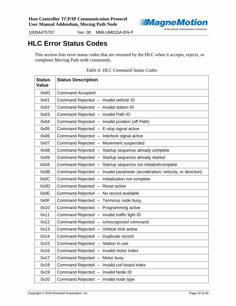
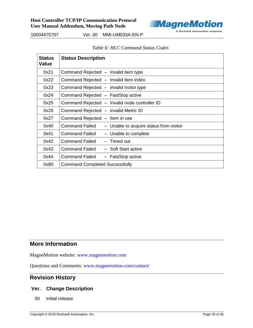
HLC Error Status Codes
This section lists error status codes that are returned by the HLC when it accepts, rejects, or
completes Moving Path node commands.
Table 6: HLC Command Status Codes
Status Value
Status Description
0x00 Command Accepted
0x01 Command Rejected – Invalid vehicle ID
0x02 Command Rejected – Invalid station ID
0x03 Command Rejected – Invalid Path ID
0x04 Command Rejected – Invalid position (off Path)
0x05 Command Rejected – E-stop signal active
0x06 Command Rejected – Interlock signal active
0x07 Command Rejected – Movement suspended
0x08 Command Rejected – Startup sequence already complete
0x09 Command Rejected – Startup sequence already started
0x0A Command Rejected – Startup sequence not initiated/complete
0x0B Command Rejected – Invalid parameter (acceleration, velocity, or direction)
0x0C Command Rejected – Initialization not complete
0x0D Command Rejected – Reset active
0x0E Command Rejected – No record available
0x0F Command Rejected – Terminus node busy
0x10 Command Rejected – Programming active
0x11 Command Rejected – Invalid traffic light ID
0x12 Command Rejected – Unrecognized command
0x13 Command Rejected – Vehicle lock active
0x14 Command Rejected – Duplicate record
0x15 Command Rejected – Station in use
0x16 Command Rejected – Invalid motor index
0x17 Command Rejected – Motor busy
0x18 Command Rejected – Invalid coil board index
0x19 Command Rejected – Invalid Node ID
0x20 Command Rejected – Invalid node type
Host Controller TCP/IP Communication Protocol
User Manual Addendum, Moving Path Node
10004475707 Ver. 00 MMI-UM033A-EN-P
Copyright © 2019 Rockwell Automation, Inc. Page 43 of 45
Table 6: HLC Command Status Codes
Status Value
Status Description
0x21 Command Rejected – Invalid item type
0x22 Command Rejected – Invalid item index
0x23 Command Rejected – Invalid motor type
0x24 Command Rejected – FastStop active
0x25 Command Rejected – Invalid node controller ID
0x26 Command Rejected – Invalid Metric ID
0x27 Command Rejected – Item in use
0x40 Command Failed – Unable to acquire status from motor
0x41 Command Failed – Unable to complete
0x42 Command Failed – Timed out
0x43 Command Failed – Soft Start active
0x44 Command Failed – FastStop active
0x80 Command Completed Successfully
More Information
MagneMotion website: www.magnemotion.com
Questions and Comments: www.magnemotion.com/contact/
Revision History
Ver. Change Description
00 Initial release
Host Controller TCP/IP Communication Protocol
User Manual Addendum, Moving Path Node
10004475707 Ver. 00 MMI-UM033A-EN-P
Copyright © 2019 Rockwell Automation, Inc. Page 44 of 45
Rockwell Automation Support
Use the following resources to access support information.
Technical Support Center Knowledgebase Articles, How-to Videos, FAQs, Chat, User Forums, and Product Notification Updates.
https://rockwellautomation.custhelp.com/
Local Technical Support Phone Numbers
Locate the phone number for your country.
http://www.rockwellautomation.com/global/support/get-support-now.page
Direct Dial Codes Find the Direct Dial Code for your product. Use the code to route your call directly to a technical support engineer.
http://www.rockwellautomation.com/global/support/direct-dial.page
Literature Library Installation Instructions, Manuals, Brochures, and Technical Data.
http://www.rockwellautomation.com/global/literature-library/overview.page
Product Compatibility and Download Center (PCDC)
Get help determining how products interact, check features and capabilities, and find associated firmware.
http://www.rockwellautomation.com/global/support/pcdc.page
Documentation Feedback Your comments will help us serve your documentation needs better. If you have any suggestions on how to improve this document, complete the How Are We Doing? form at http://literature.rockwellautomation.com/idc/groups/literature/documents/du/ra-du002_-en-e.pdf.
Rockwell Automation maintains current product environmental information on its website at http://www.rockwellautomation.com/rockwellautomation/about-us/sustainability-ethics/product-environmental-compliance.page.
Product certificates are located in the Rockwell Automation Literature Library: http://www.rockwellautomation.com/global/literature-library/overview.page
Allen-Bradley, Compact I/O, CompactLogix, ControlLogix, DH+, DriveLogix, FactoryTalk, FLEX, Logix5000, PanelBuilder, PanelView, PLC-2, PLC-3, PLC-5, POINT I/O, PowerFlex, Rockwell Automation, Rockwell Software, RSLinx, RSLogix, RSNetWorx, RSView, SLC, SoftLogix, Studio 5000, and Studio 5000 Logix Designer are trademarks of Rockwell Automation, Inc.
Trademarks not belonging to Rockwell Automation are property of their respective companies.
Rockwell Otomasyon Ticaret A.Ş., Kar Plaza İş Merkezi E Blok Kat:6 34752 İçerenköy, İstanbul, Tel: +90 (216) 5698400
www.rockwellautomation.com
Host Controller TCP/IP Communication Protocol
User Manual Addendum, Moving Path Node
10004475707 Ver. 00 MMI-UM033A-EN-P
Copyright © 2019 Rockwell Automation, Inc. Page 45 of 45
Power, Control and Information Solutions Headquarters
Americas: Rockwell Automation, 1201 South Second Street, Milwaukee, WI 53204-2496 USA, Tel: (1) 414.382.2000, Fax: (1) 414.382.4444 Europe/Middle East/Africa: Rockwell Automation NV, Pegasus Park, De Kleetlaan 12a, 1831 Diegem, Belgium, Tel: (32) 2 663 0600, Fax: (32) 2 663 0640 Asia Pacific: Rockwell Automation, Level 14, Core F, Cyberport 3, 100 Cyberport Road, Hong Kong, Tel: (852) 2887 4788, Fax: (852) 2508 1846A
Recommended


![Problem Solving and Search - UvAsolve_depthfirst(Node, [Node|Path]) :-depthfirst(Node, Path). Next the actual algorithm: Stop if the current Node is a goal state; otherwise move to](https://img.pdfslide.us/doc/110x75/5f34cfe97082ce293b3f9dc1/problem-solving-and-search-uva-solvedepthfirstnode-nodepath-depthfirstnode.jpg)