ADD 3.0: Rethinking Drivers and Decisions in the Design Process
Rick KazmanHumberto Cervantes
SATURN 2015
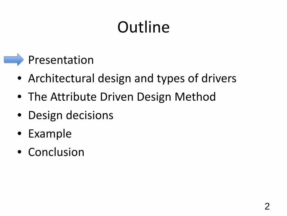
Outline
• Presentation• Architectural design and types of drivers• The Attribute Driven Design Method• Design decisions• Example• Conclusion
2
Speakers
• Rick Kazman• Humberto Cervantes
3
Learning Objectives
• At the end of the presentation, participants should be able to understand:– The different types of architectural drivers– What are design concepts and the decisions
regarding their selection– What ADD is and how an architecture is designed
iteratively using this method
4
Outline
• Presentation• Architectural design and types of drivers• The Attribute Driven Design Method• Design decisions• Example • Conclusion
5
Software Architecture
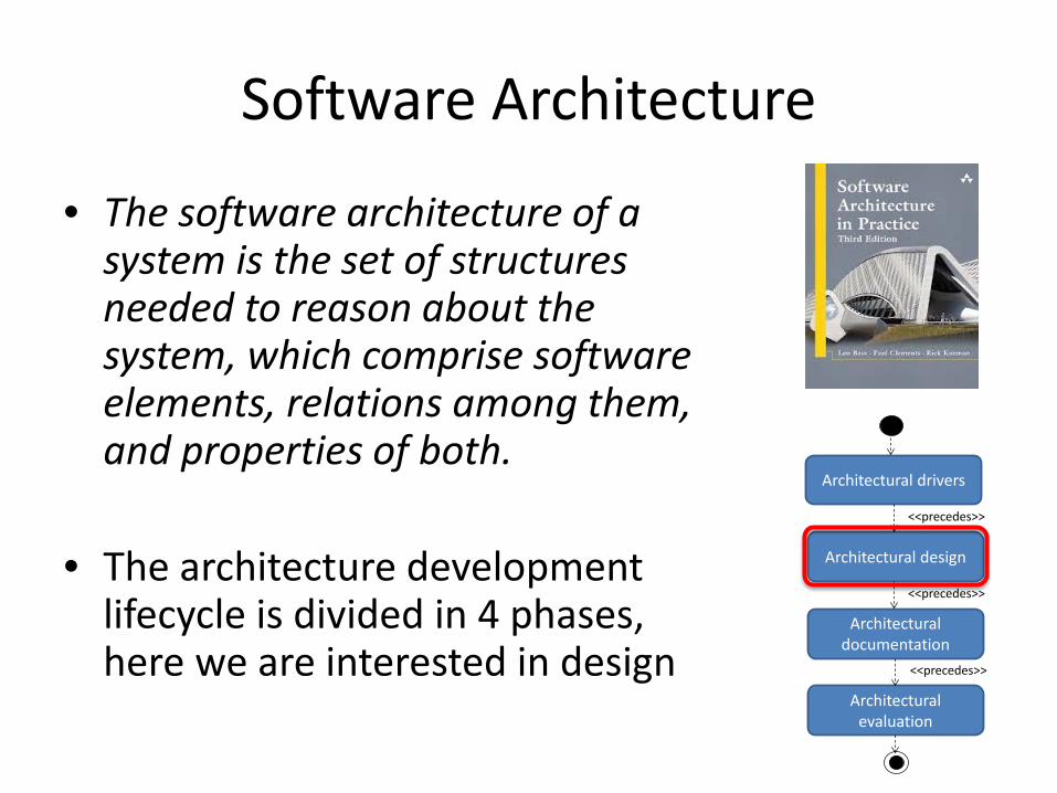
• The software architecture of a system is the set of structures needed to reason about the system, which comprise software elements, relations among them, and properties of both.
• The architecture development lifecycle is divided in 4 phases, here we are interested in design
Architectural drivers
Architectural design
Architectural documentation
Architectural evaluation
<<precedes>>
<<precedes>>
<<precedes>>
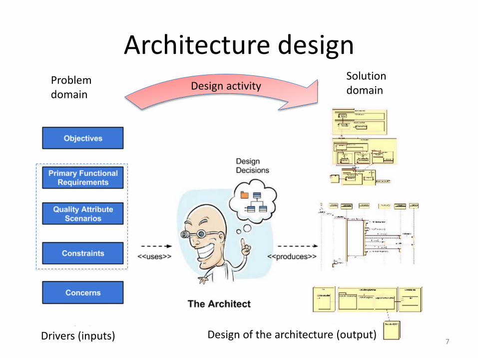
Architecture design
Drivers (inputs) Design of the architecture (output)
Design activityProblem domain
Solution domain
7
Architectural drivers
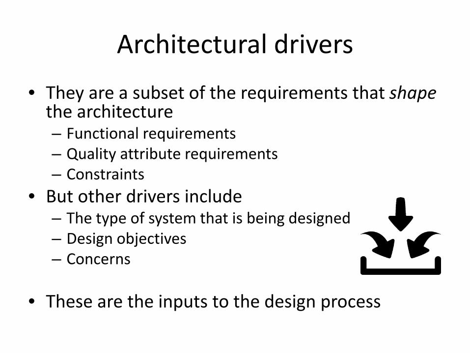
• They are a subset of the requirements that shapethe architecture– Functional requirements– Quality attribute requirements– Constraints
• But other drivers include– The type of system that is being designed– Design objectives– Concerns
• These are the inputs to the design process
Functional drivers
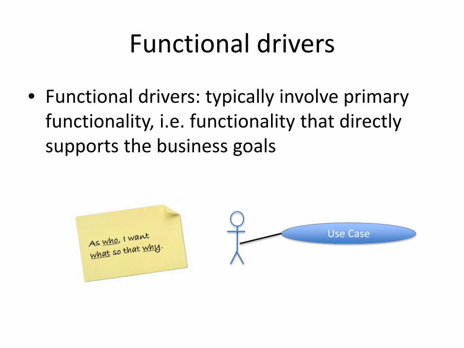
• Functional drivers: typically involve primary functionality, i.e. functionality that directly supports the business goals
Use Case
Quality attribute drivers
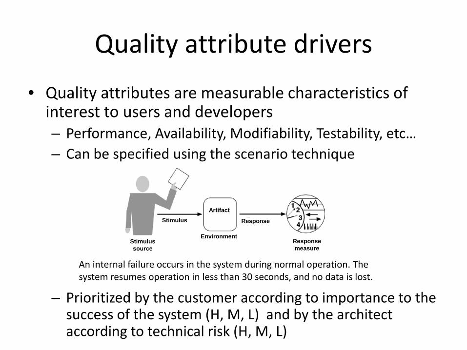
• Quality attributes are measurable characteristics of interest to users and developers– Performance, Availability, Modifiability, Testability, etc…– Can be specified using the scenario technique
– Prioritized by the customer according to importance to the success of the system (H, M, L) and by the architect according to technical risk (H, M, L)
An internal failure occurs in the system during normal operation. The system resumes operation in less than 30 seconds, and no data is lost.
Stimulussource
Stimulus
Environment
Response
Response measure
Artifact
Constraints
• Constraints are limitations or restrictions– They may be technical or organizational– They may originate from the customer but also
from the development organization– Usually limit the alternatives that can be
considered for particular design decisions– They can actually be
your “friends”
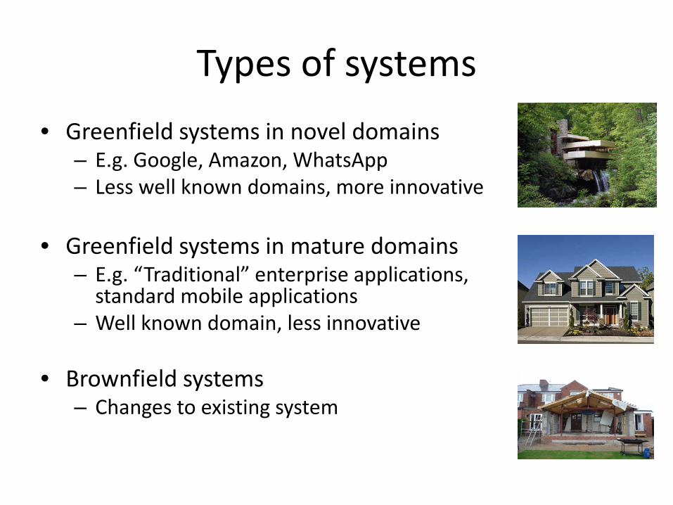
Types of systems• Greenfield systems in novel domains
– E.g. Google, Amazon, WhatsApp– Less well known domains, more innovative
• Greenfield systems in mature domains– E.g. “Traditional” enterprise applications,
standard mobile applications– Well known domain, less innovative
• Brownfield systems– Changes to existing system
Architecture design objectives
• Before you can begin you need to be clear about why you are designing. Your objectives will change what and how you design, e.g.– For a pre-sales proposal, which usually involves the
rapid design of an initial solution in order to produce an estimate
– For a custom system with established time and costs and which may not evolve much once released
– For a new increment or release of a continuously evolving system
Concerns
• Concerns represent design decisions that should be made whether or not they are stated explicitly as part of the goals or the requirements. Examples include:– Creating an overall logical and physical structure– Input validation– Exception management and logging– Communications – Deployment and updating– Data migration and backup– Organization of the codebase
Outline
• Presentation• Architectural design and types of drivers• The Attribute Driven Design Method• Design decisions• Example• Conclusion
15
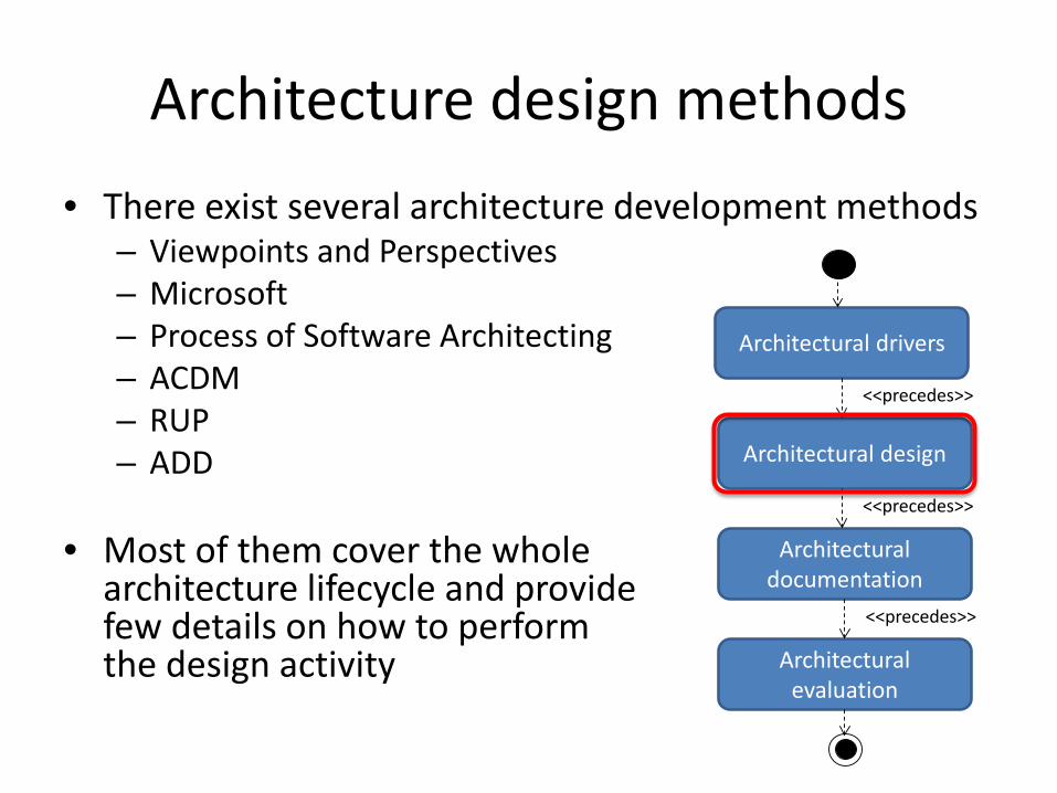
Architecture design methods• There exist several architecture development methods
– Viewpoints and Perspectives– Microsoft– Process of Software Architecting– ACDM– RUP– ADD
• Most of them cover the wholearchitecture lifecycle and providefew details on how to performthe design activity
Architectural drivers
Architectural design
Architectural documentation
Architectural evaluation
<<precedes>>
<<precedes>>
<<precedes>>
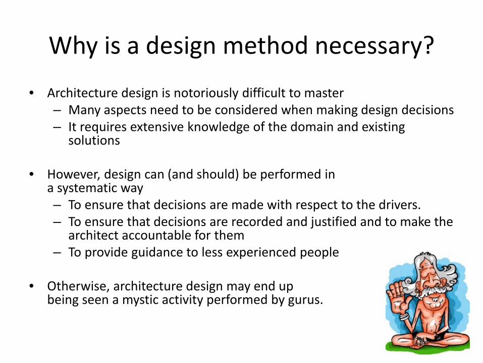
Why is a design method necessary?
• Architecture design is notoriously difficult to master– Many aspects need to be considered when making design decisions– It requires extensive knowledge of the domain and existing
solutions
• However, design can (and should) be performed in a systematic way– To ensure that decisions are made with respect to the drivers.– To ensure that decisions are recorded and justified and to make the
architect accountable for them– To provide guidance to less experienced people
• Otherwise, architecture design may end up being seen a mystic activity performed by gurus.
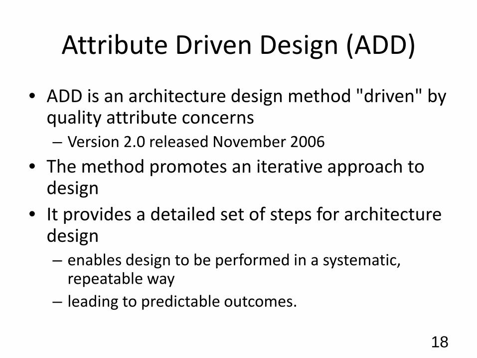
Attribute Driven Design (ADD)
• ADD is an architecture design method "driven" by quality attribute concerns– Version 2.0 released November 2006
• The method promotes an iterative approach to design
• It provides a detailed set of steps for architecture design– enables design to be performed in a systematic,
repeatable way– leading to predictable outcomes.
18
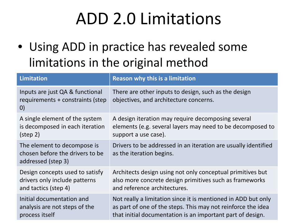
ADD 2.0 Limitations• Using ADD in practice has revealed some
limitations in the original methodLimitation Reason why this is a limitation
Inputs are just QA & functional requirements + constraints (step 0)
There are other inputs to design, such as the design objectives, and architecture concerns.
A single element of the system is decomposed in each iteration (step 2)
A design iteration may require decomposing several elements (e.g. several layers may need to be decomposed to support a use case).
The element to decompose is chosen before the drivers to be addressed (step 3)
Drivers to be addressed in an iteration are usually identified as the iteration begins.
Design concepts used to satisfy drivers only include patterns and tactics (step 4)
Architects design using not only conceptual primitives but also more concrete design primitives such as frameworks and reference architectures.
Initial documentation and analysis are not steps of the process itself
Not really a limitation since it is mentioned in ADD but only as part of one of the steps. This may not reinforce the idea that initial documentation is an important part of design.
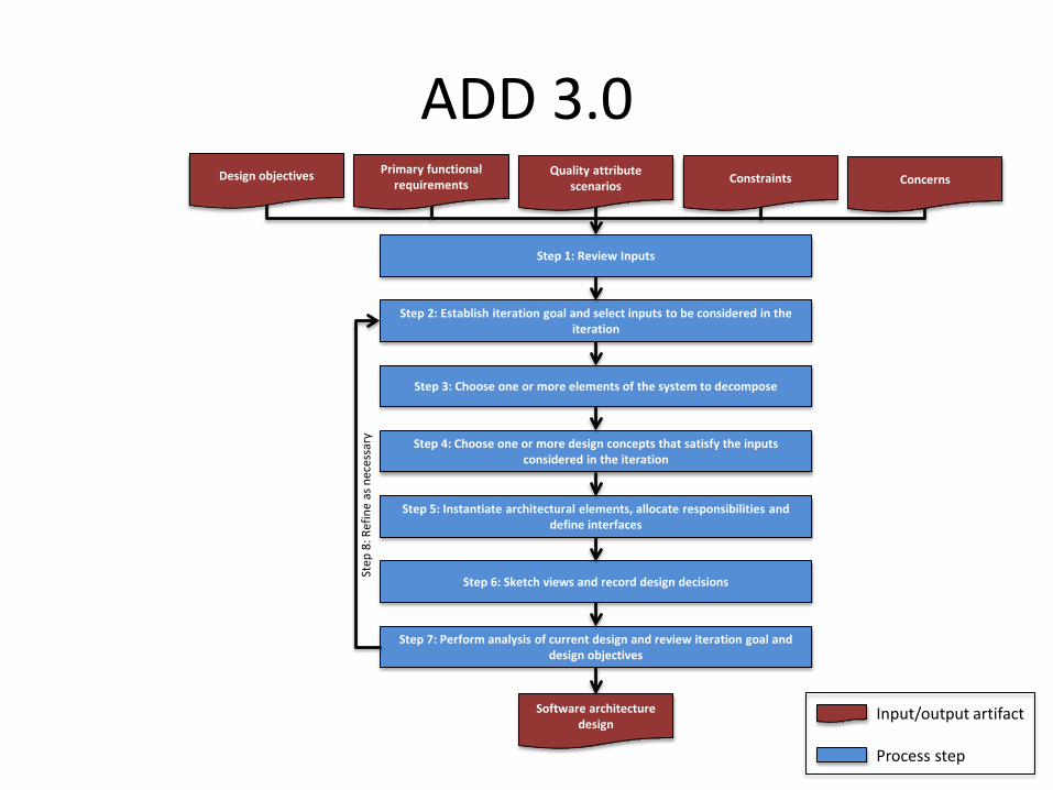
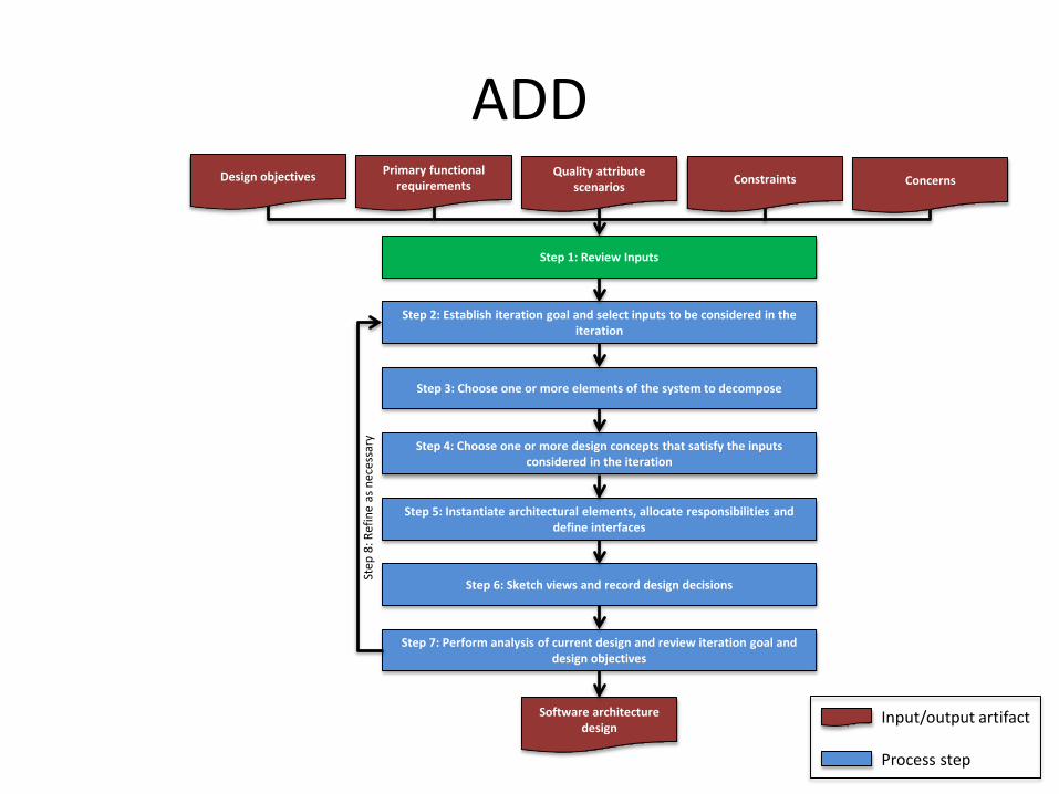
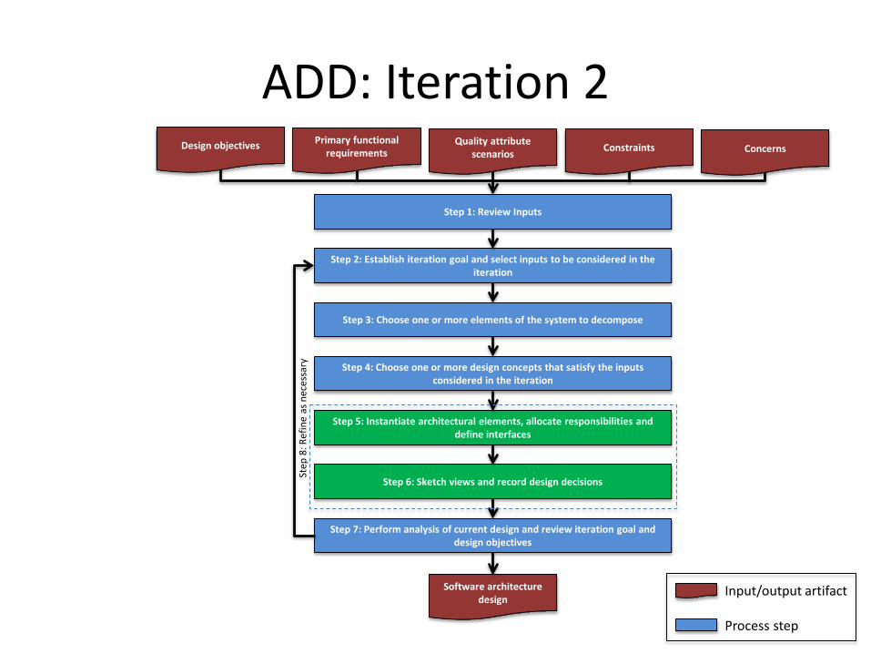
ADD 3.0Design objectives Primary functional
requirementsQuality attribute
scenarios Constraints Concerns
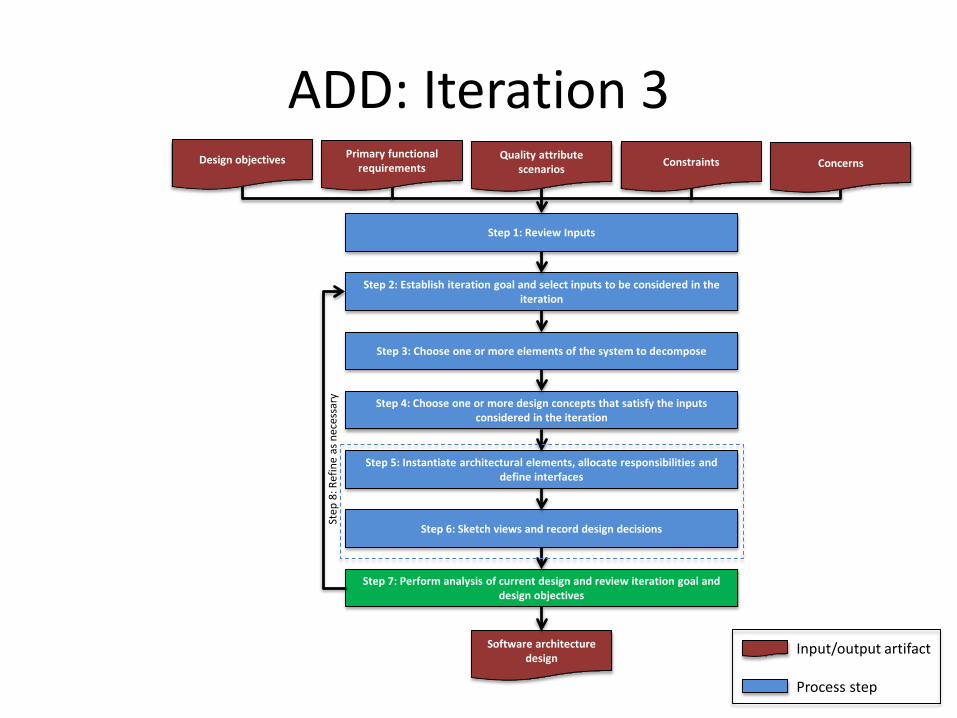
Step 1: Review Inputs
Step 2: Establish iteration goal and select inputs to be considered in the iteration
Step 3: Choose one or more elements of the system to decompose
Step 4: Choose one or more design concepts that satisfy the inputs considered in the iteration
Step 5: Instantiate architectural elements, allocate responsibilities and define interfaces
Step 6: Sketch views and record design decisions
Step 7: Perform analysis of current design and review iteration goal and design objectives
Software architecture design
Input/output artifact
Process step
Step
8: R
efin
e as
nec
essa
ry
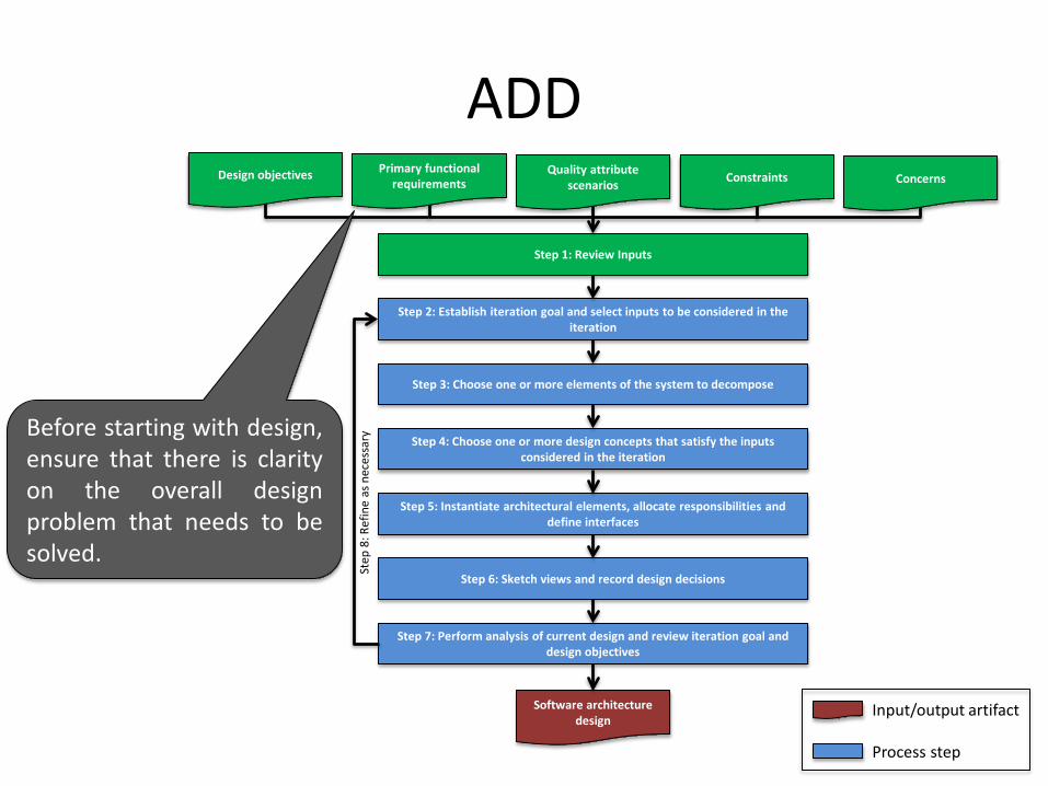
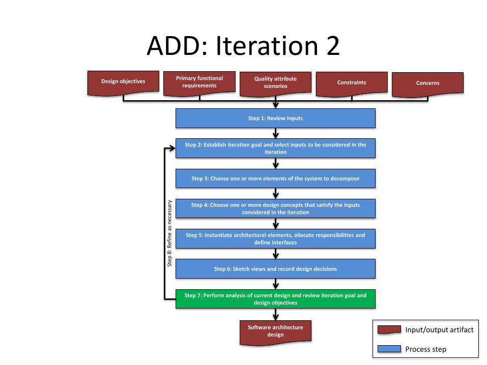
ADDDesign objectives Primary functional
requirementsQuality attribute
scenarios Constraints Concerns
Step 1: Review Inputs
Step 2: Establish iteration goal and select inputs to be considered in the iteration
Step 3: Choose one or more elements of the system to decompose
Step 4: Choose one or more design concepts that satisfy the inputs considered in the iteration
Step 5: Instantiate architectural elements, allocate responsibilities and define interfaces
Step 6: Sketch views and record design decisions
Step 7: Perform analysis of current design and review iteration goal and design objectives
Software architecture design
Input/output artifact
Process step
Step
8: R
efin
e as
nec
essa
ryBefore starting with design,ensure that there is clarityon the overall designproblem that needs to besolved.
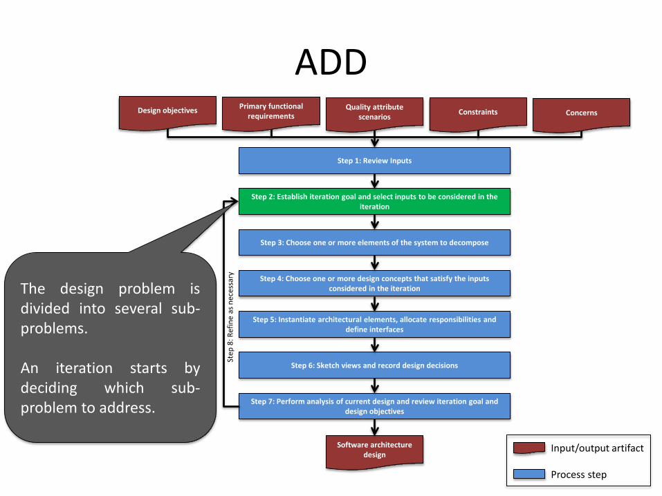
ADDDesign objectives Primary functional
requirementsQuality attribute
scenarios Constraints Concerns
Step 1: Review Inputs
Step 2: Establish iteration goal and select inputs to be considered in the iteration
Step 3: Choose one or more elements of the system to decompose
Step 4: Choose one or more design concepts that satisfy the inputs considered in the iteration
Step 5: Instantiate architectural elements, allocate responsibilities and define interfaces
Step 6: Sketch views and record design decisions
Step 7: Perform analysis of current design and review iteration goal and design objectives
Software architecture design
Input/output artifact
Process step
Step
8: R
efin
e as
nec
essa
ry
The design problem isdivided into several sub-problems.
An iteration starts bydeciding which sub-problem to address.
ADDDesign objectives Primary functional
requirementsQuality attribute
scenarios Constraints Concerns
Step 1: Review Inputs
Step 2: Establish iteration goal and select inputs to be considered in the iteration
Step 3: Choose one or more elements of the system to decompose
Step 4: Choose one or more design concepts that satisfy the inputs considered in the iteration
Step 5: Instantiate architectural elements, allocate responsibilities and define interfaces
Step 6: Sketch views and record design decisions
Step 7: Perform analysis of current design and review iteration goal and design objectives
Software architecture design
Input/output artifact
Process step
Step
8: R
efin
e as
nec
essa
ry
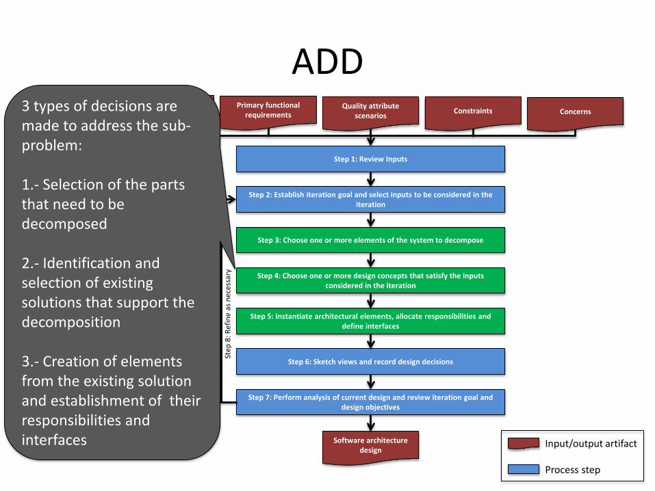
3 types of decisions are made to address the sub-problem:
1.- Selection of the parts that need to be decomposed
2.- Identification and selection of existing solutions that support the decomposition
3.- Creation of elements from the existing solution and establishment of their responsibilities and interfaces
ADDDesign objectives Primary functional
requirementsQuality attribute
scenarios Constraints Concerns
Step 1: Review Inputs
Step 2: Establish iteration goal and select inputs to be considered in the iteration
Step 3: Choose one or more elements of the system to decompose
Step 4: Choose one or more design concepts that satisfy the inputs considered in the iteration
Step 5: Instantiate architectural elements, allocate responsibilities and define interfaces
Step 6: Sketch views and record design decisions
Step 7: Perform analysis of current design and review iteration goal and design objectives
Software architecture design
Input/output artifact
Process step
Step
8: R
efin
e as
nec
essa
ry
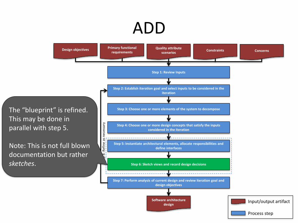
The “blueprint” is refined. This may be done in parallel with step 5.
Note: This is not full blown documentation but rather sketches.
ADDDesign objectives Primary functional
requirementsQuality attribute
scenarios Constraints Concerns
Step 1: Review Inputs
Step 2: Establish iteration goal and select inputs to be considered in the iteration
Step 3: Choose one or more elements of the system to decompose
Step 4: Choose one or more design concepts that satisfy the inputs considered in the iteration
Step 5: Instantiate architectural elements, allocate responsibilities and define interfaces
Step 6: Sketch views and record design decisions
Step 7: Perform analysis of current design and review iteration goal and design objectives
Software architecture design
Input/output artifact
Process step
Step
8: R
efin
e as
nec
essa
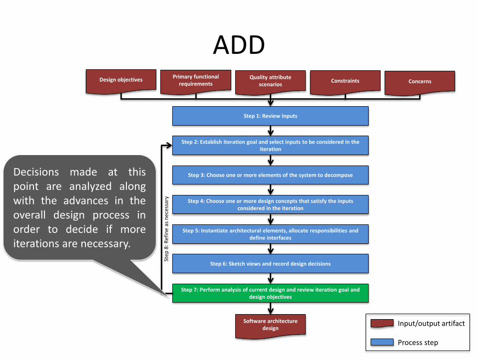
ryDecisions made at thispoint are analyzed alongwith the advances in theoverall design process inorder to decide if moreiterations are necessary.
ADDDesign objectives Primary functional
requirementsQuality attribute
scenarios Constraints Concerns
Step 1: Review Inputs
Step 2: Establish iteration goal and select inputs to be considered in the iteration
Step 3: Choose one or more elements of the system to decompose
Step 4: Choose one or more design concepts that satisfy the inputs considered in the iteration
Step 5: Instantiate architectural elements, allocate responsibilities and define interfaces
Step 6: Sketch views and record design decisions
Step 7: Perform analysis of current design and review iteration goal and design objectives
Software architecture design
Input/output artifact
Process step
Step
8: R
efin
e as
nec
essa
ry
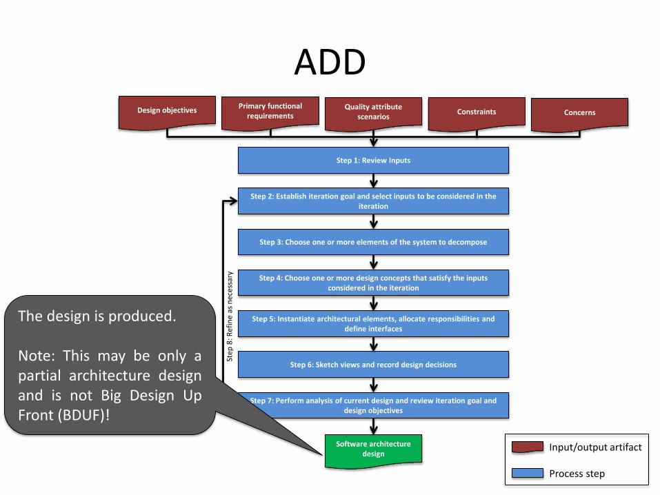
The design is produced.
Note: This may be only apartial architecture designand is not Big Design UpFront (BDUF)!
Outline
• Presentation• Architectural design and types of drivers• The Attribute Driven Design Method• Design decisions• Example• Conclusion
27
Design decisions
• The design process involves different making design decisions– Step 3: Selecting elements to decompose– Step 4: Choosing one or more design
concepts that satisfy the inputs consideredin the iteration
– Step 5: Instantiating architectural elements, allocating responsibilities and defining interfaces
• Step 4 (selecting design decisions) can be particularly challenging…
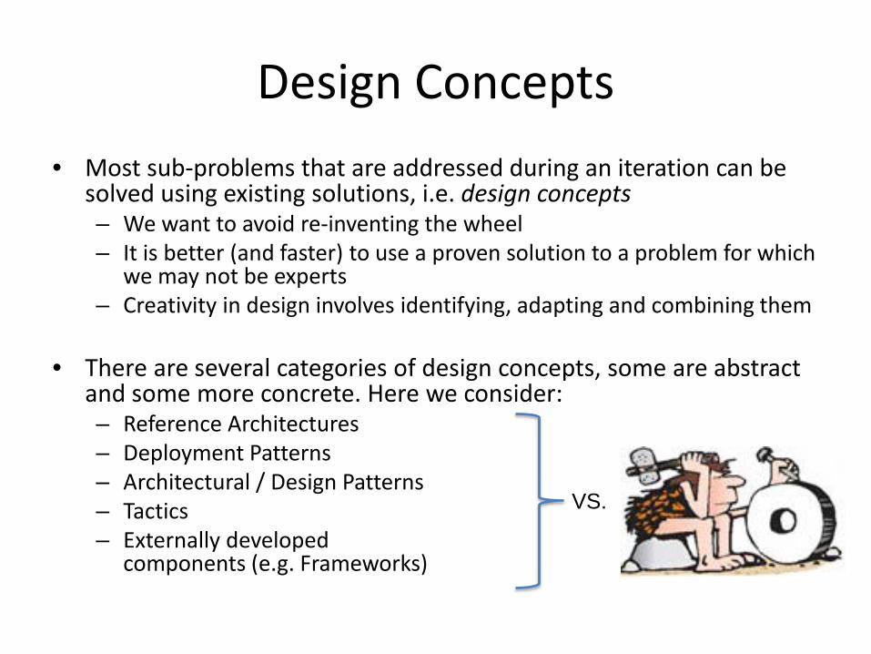
Design Concepts• Most sub-problems that are addressed during an iteration can be
solved using existing solutions, i.e. design concepts– We want to avoid re-inventing the wheel– It is better (and faster) to use a proven solution to a problem for which
we may not be experts– Creativity in design involves identifying, adapting and combining them
• There are several categories of design concepts, some are abstract and some more concrete. Here we consider:– Reference Architectures– Deployment Patterns– Architectural / Design Patterns– Tactics– Externally developed
components (e.g. Frameworks)
VS.
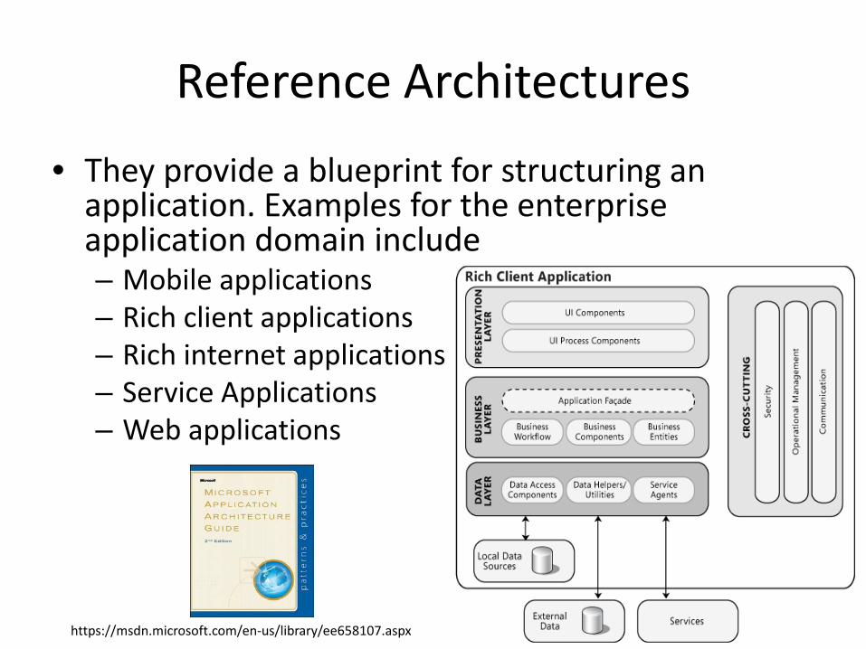
Reference Architectures
• They provide a blueprint for structuring an application. Examples for the enterprise application domain include– Mobile applications– Rich client applications– Rich internet applications– Service Applications– Web applications
https://msdn.microsoft.com/en-us/library/ee658107.aspx
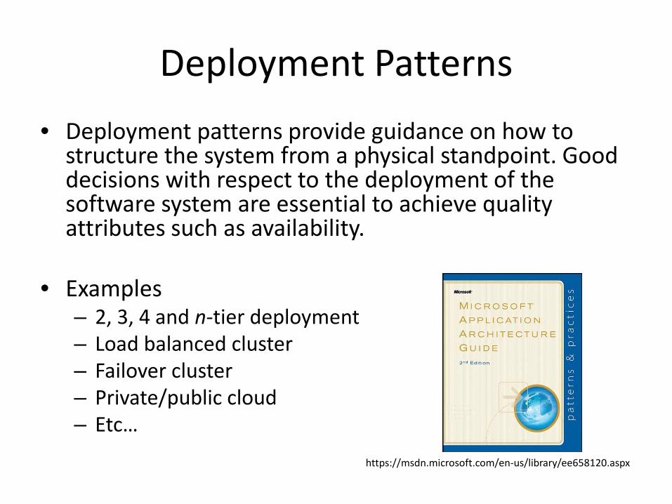
Deployment Patterns• Deployment patterns provide guidance on how to
structure the system from a physical standpoint. Good decisions with respect to the deployment of the software system are essential to achieve quality attributes such as availability.
• Examples– 2, 3, 4 and n-tier deployment– Load balanced cluster– Failover cluster– Private/public cloud– Etc…
https://msdn.microsoft.com/en-us/library/ee658120.aspx
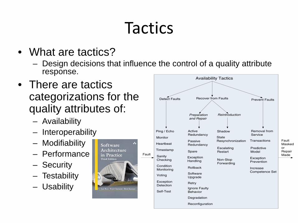
Tactics• What are tactics?
– Design decisions that influence the control of a quality attribute response.
• There are tactics categorizations for the quality attributes of:– Availability– Interoperability– Modifiability– Performance– Security– Testability– Usability
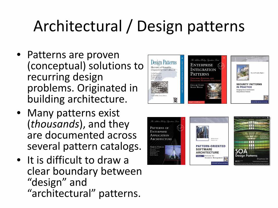
Architectural / Design patterns
• Patterns are proven (conceptual) solutions to recurring design problems. Originated in building architecture.
• Many patterns exist (thousands), and they are documented across several pattern catalogs.
• It is difficult to draw a clear boundary between “design” and “architectural” patterns.
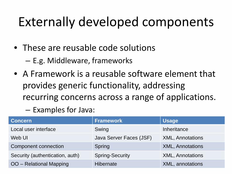
Externally developed components
• These are reusable code solutions– E.g. Middleware, frameworks
• A Framework is a reusable software element that provides generic functionality, addressing recurring concerns across a range of applications.– Examples for Java:
Concern Framework UsageLocal user interface Swing InheritanceWeb UI Java Server Faces (JSF) XML, AnnotationsComponent connection Spring XML, Annotations
Security (authentication, auth) Spring-Security XML, AnnotationsOO – Relational Mapping Hibernate XML, annotations
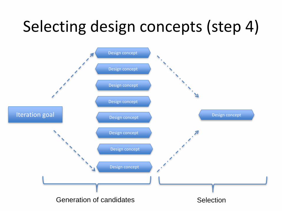
Selecting design concepts (step 4)
Iteration goal Design concept
SelectionGeneration of candidates
Design concept
Design concept
Design concept
Design concept
Design concept
Design concept
Design concept
Design concept
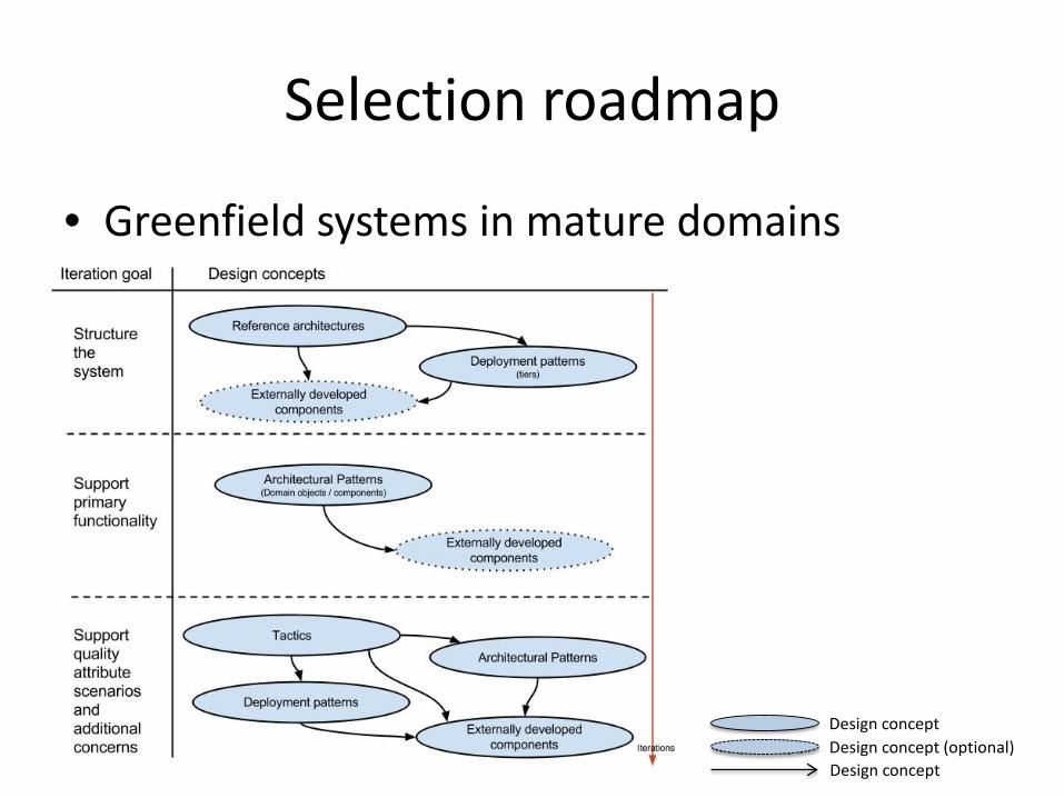
Selection roadmap
Design conceptDesign concept (optional)Design concept
• Greenfield systems in mature domains
Outline
• Presentation• Architectural design and types of drivers• The Attribute Driven Design Method• Design decisions• Example• Conclusion
37
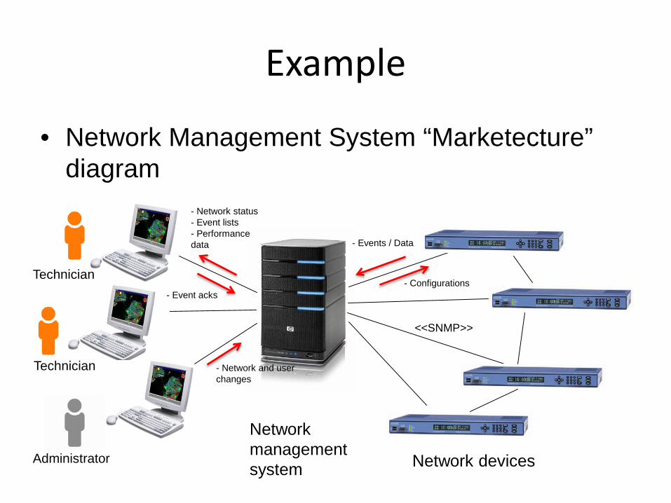
Example
• Network Management System “Marketecture” diagram
Network devices
Network management system
<<SNMP>>
Technician
Technician
Administrator
- Events / Data
- Configurations
- Network status- Event lists- Performance data
- Event acks
- Network and user changes
ADDDesign objectives Primary functional
requirementsQuality attribute
scenarios Constraints Concerns
Step 1: Review Inputs
Step 2: Establish iteration goal and select inputs to be considered in the iteration
Step 3: Choose one or more elements of the system to decompose
Step 4: Choose one or more design concepts that satisfy the inputs considered in the iteration
Step 5: Instantiate architectural elements, allocate responsibilities and define interfaces
Step 6: Sketch views and record design decisions
Step 7: Perform analysis of current design and review iteration goal and design objectives
Software architecture design
Input/output artifact
Process step
Step
8: R
efin
e as
nec
essa
ry
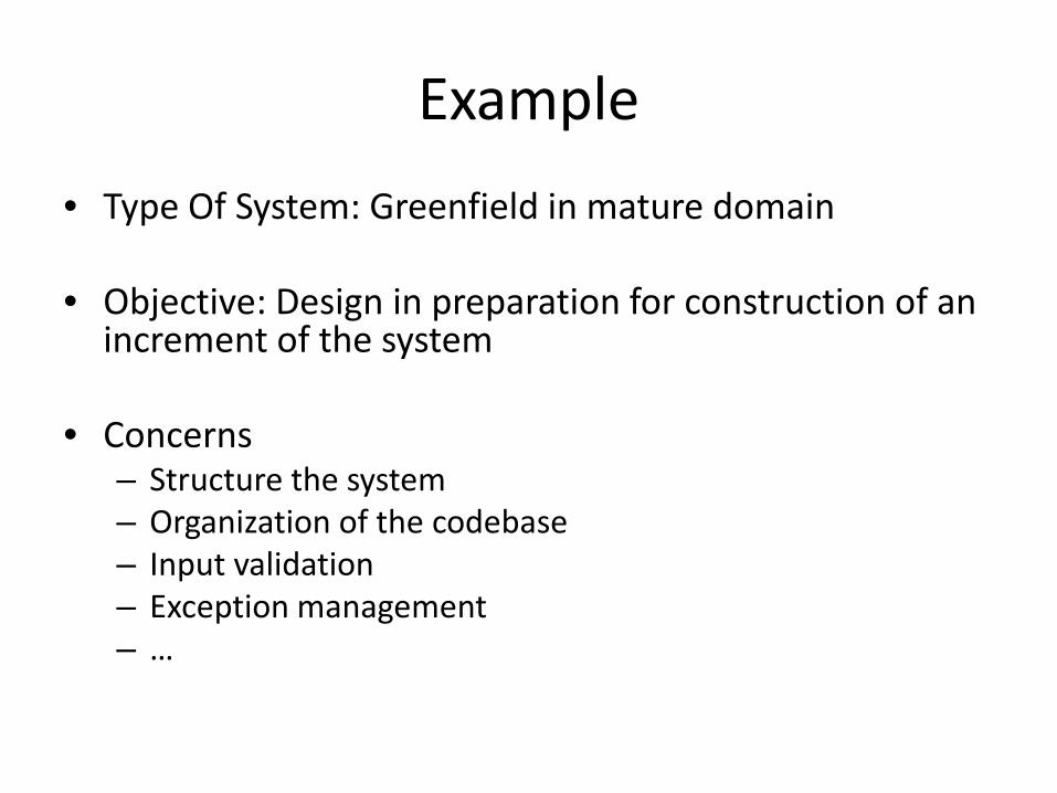
Example• Type Of System: Greenfield in mature domain
• Objective: Design in preparation for construction of an increment of the system
• Concerns– Structure the system– Organization of the codebase– Input validation– Exception management– …
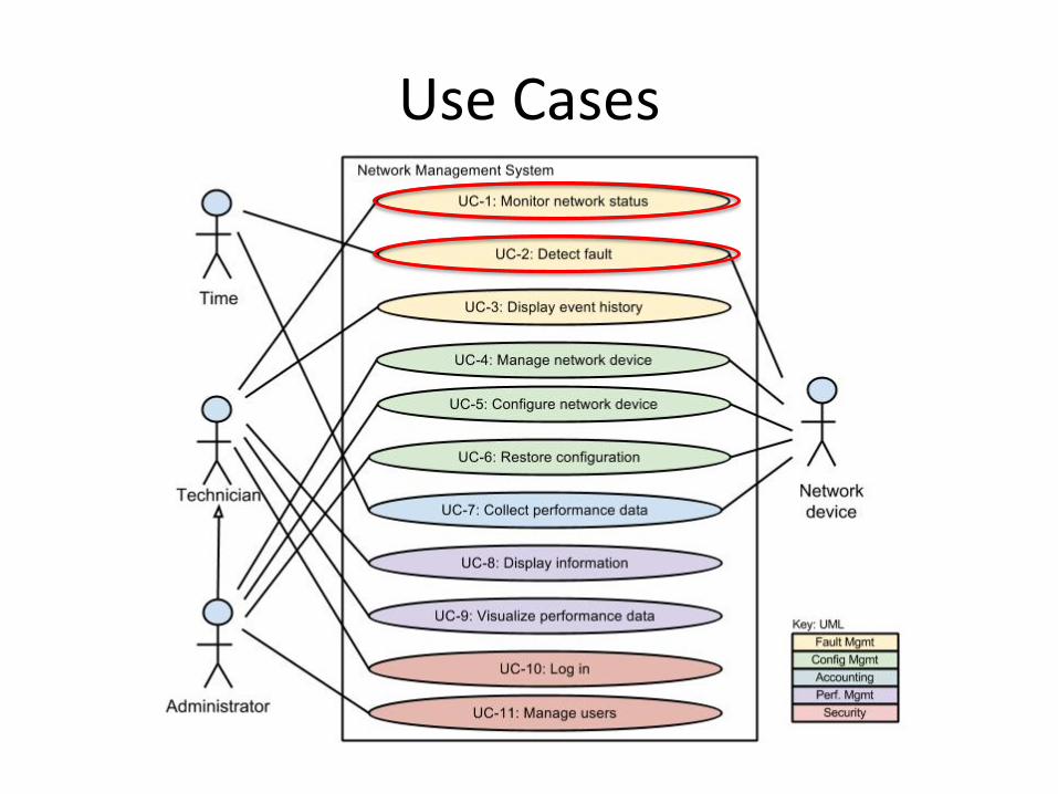
Use Cases
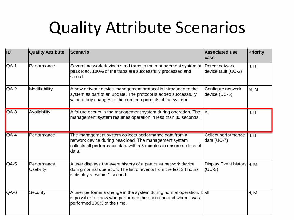
Quality Attribute ScenariosID Quality Attribute Scenario Associated use
casePriority
QA-1 Performance Several network devices send traps to the management system at peak load. 100% of the traps are successfully processed and stored.
Detect network device fault (UC-2)
H, H
QA-2 Modifiability A new network device management protocol is introduced to the system as part of an update. The protocol is added successfully without any changes to the core components of the system.
Configure network device (UC-5)
M, M
QA-3 Availability A failure occurs in the management system during operation. The management system resumes operation in less than 30 seconds.
All H, H
QA-4 Performance The management system collects performance data from a network device during peak load. The management system collects all performance data within 5 minutes to ensure no loss of data.
Collect performancedata (UC-7)
H, H
QA-5 Performance, Usability
A user displays the event history of a particular network device during normal operation. The list of events from the last 24 hours is displayed within 1 second.
Display Event history (UC-3)
H, M
QA-6 Security A user performs a change in the system during normal operation. It is possible to know who performed the operation and when it was performed 100% of the time.
All H, M
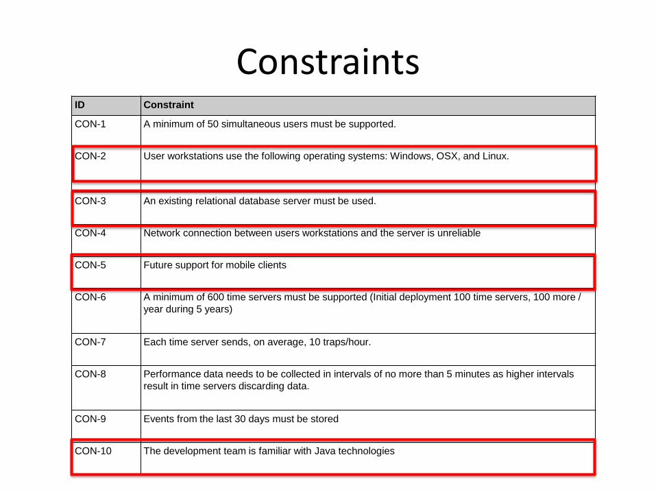
ConstraintsID Constraint
CON-1 A minimum of 50 simultaneous users must be supported.
CON-2 User workstations use the following operating systems: Windows, OSX, and Linux.
CON-3 An existing relational database server must be used.
CON-4 Network connection between users workstations and the server is unreliable
CON-5 Future support for mobile clients
CON-6 A minimum of 600 time servers must be supported (Initial deployment 100 time servers, 100 more / year during 5 years)
CON-7 Each time server sends, on average, 10 traps/hour.
CON-8 Performance data needs to be collected in intervals of no more than 5 minutes as higher intervals result in time servers discarding data.
CON-9 Events from the last 30 days must be stored
CON-10 The development team is familiar with Java technologies

ADD: Iteration 1Design objectives Primary functional
requirementsQuality attribute
scenarios Constraints Concerns
Step 1: Review Inputs
Step 2: Establish iteration goal and select inputs to be considered in the iteration
Step 3: Choose one or more elements of the system to decompose
Step 4: Choose one or more design concepts that satisfy the inputs considered in the iteration
Step 5: Instantiate architectural elements, allocate responsibilities and define interfaces
Step 6: Sketch views and record design decisions
Step 7: Perform analysis of current design and review iteration goal and design objectives
Software architecture design
Input/output artifact
Process step
Step
8: R
efin
e as
nec
essa
ry
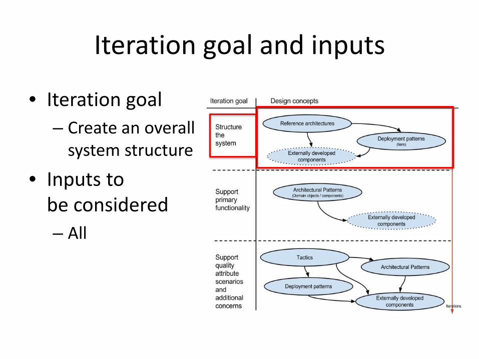
Iteration goal and inputs
• Iteration goal– Create an overall
system structure
• Inputs to be considered– All
ADD: Iteration 1Design objectives Primary functional
requirementsQuality attribute
scenarios Constraints Concerns
Step 1: Review Inputs
Step 2: Establish iteration goal and select inputs to be considered in the iteration
Step 3: Choose one or more elements of the system to decompose
Step 4: Choose one or more design concepts that satisfy the inputs considered in the iteration
Step 5: Instantiate architectural elements, allocate responsibilities and define interfaces
Step 6: Sketch views and record design decisions
Step 7: Perform analysis of current design and review iteration goal and design objectives
Software architecture design
Input/output artifact
Process step
Step
8: R
efin
e as
nec
essa
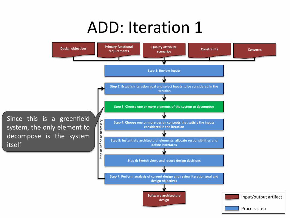
rySince this is a greenfieldsystem, the only element todecompose is the systemitself
ADD: Iteration 1Design objectives Primary functional
requirementsQuality attribute
scenarios Constraints Concerns
Step 1: Review Inputs
Step 2: Establish iteration goal and select inputs to be considered in the iteration
Step 3: Choose one or more elements of the system to decompose
Step 4: Choose one or more design concepts that satisfy the inputs considered in the iteration
Step 5: Instantiate architectural elements, allocate responsibilities and define interfaces
Step 6: Sketch views and record design decisions
Step 7: Perform analysis of current design and review iteration goal and design objectives
Software architecture design
Input/output artifact
Process step
Step
8: R
efin
e as
nec
essa
ry
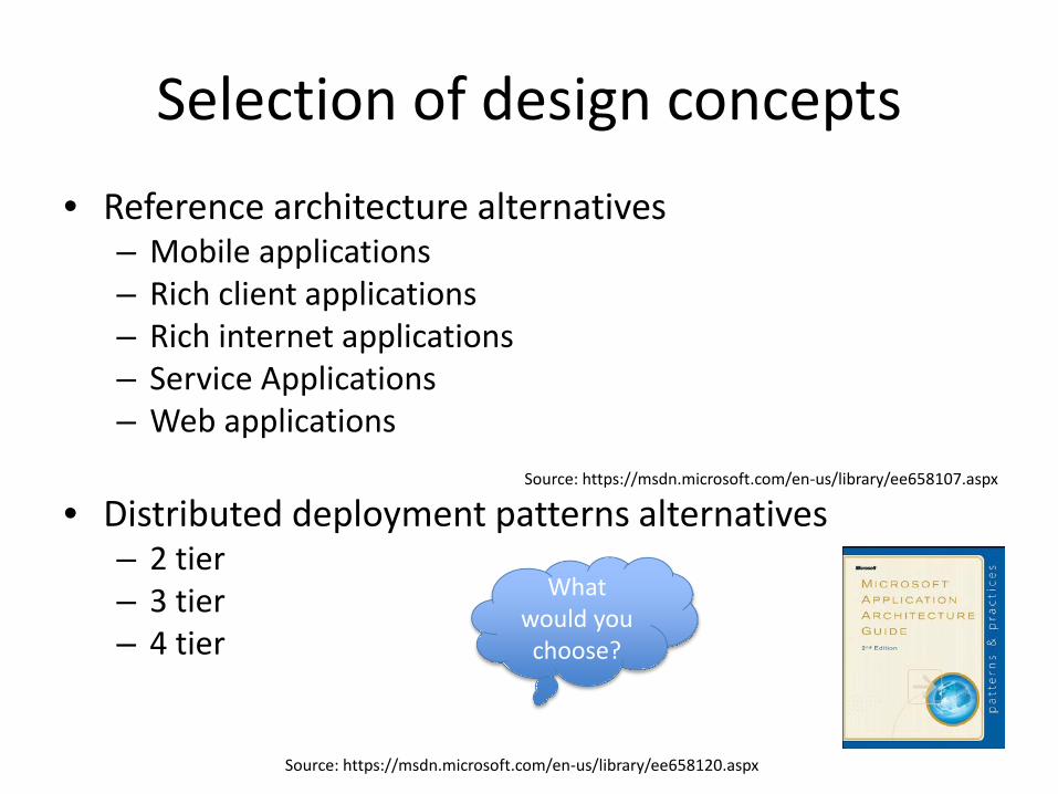
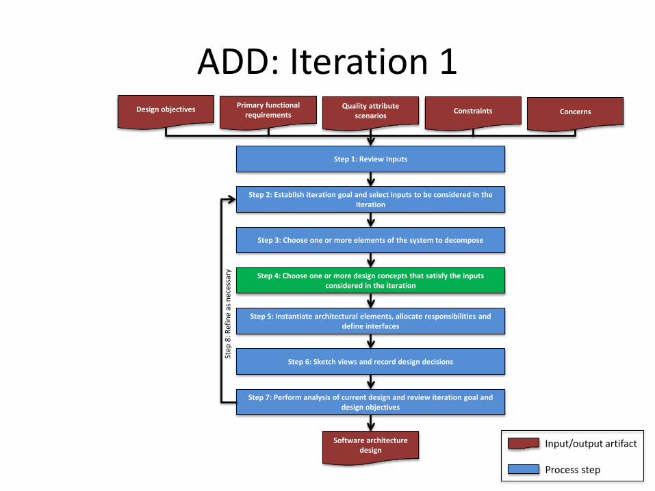
Selection of design concepts• Reference architecture alternatives
– Mobile applications– Rich client applications– Rich internet applications– Service Applications– Web applications
• Distributed deployment patterns alternatives– 2 tier– 3 tier– 4 tier
Source: https://msdn.microsoft.com/en-us/library/ee658107.aspx
Source: https://msdn.microsoft.com/en-us/library/ee658120.aspx
What would you choose?

Design decisions
• Two reference architectures are chosen
• Distributed deployment patterns alternatives– 3 tier
Design decision Rationale
Rich client application on the client side
- Supports rich user interface- Portability (CON-2)
Service application on the server side
- Support mobile clients in the future (CON-5)
3 Tier application - Existing database server (CON-3)
… …
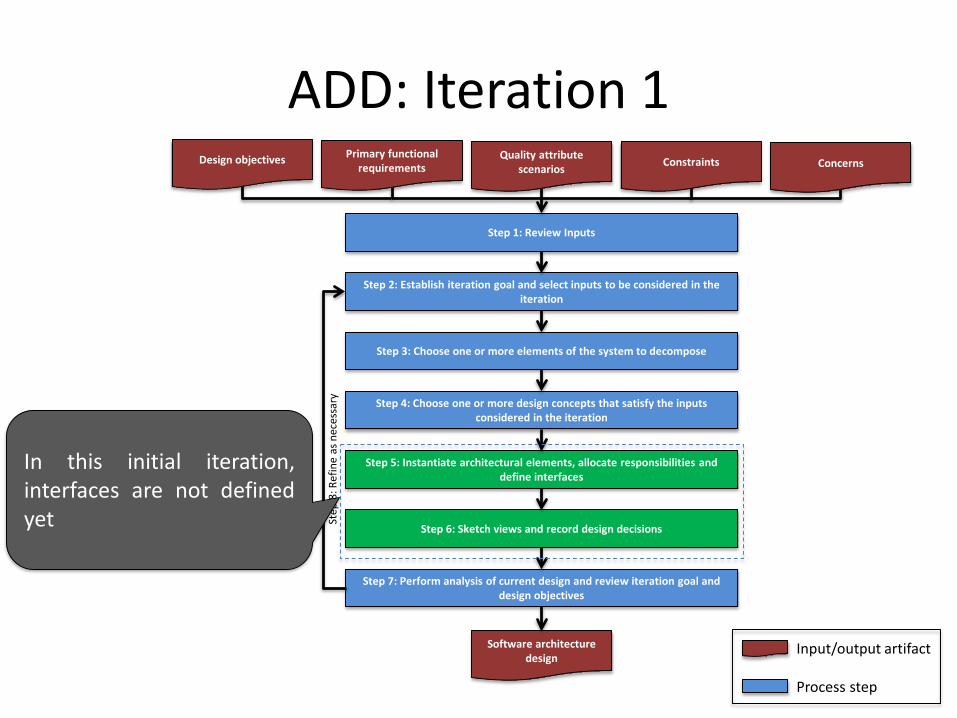
ADD: Iteration 1Design objectives Primary functional
requirementsQuality attribute
scenarios Constraints Concerns
Step 1: Review Inputs
Step 2: Establish iteration goal and select inputs to be considered in the iteration
Step 3: Choose one or more elements of the system to decompose
Step 4: Choose one or more design concepts that satisfy the inputs considered in the iteration
Step 5: Instantiate architectural elements, allocate responsibilities and define interfaces
Step 6: Sketch views and record design decisions
Step 7: Perform analysis of current design and review iteration goal and design objectives
Software architecture design
Input/output artifact
Process step
Step
8: R
efin
e as
nec
essa
ry
In this initial iteration,interfaces are not definedyet
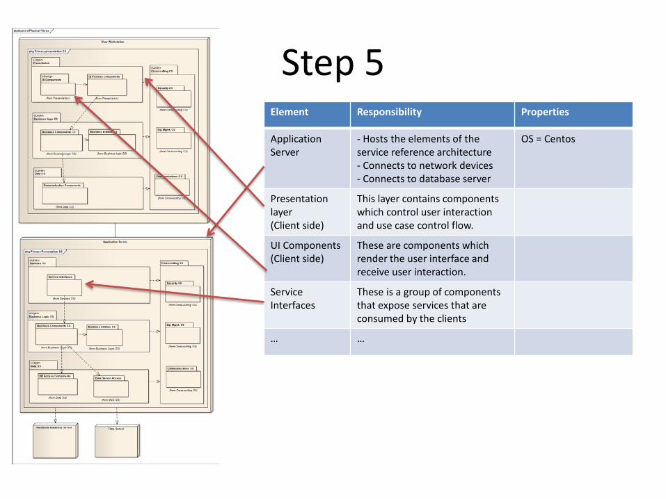
Step 5
• hElement Responsibility Properties
ApplicationServer
- Hosts the elements of theservice reference architecture - Connects to network devices- Connects to database server
OS = Centos
Presentation layer(Client side)
This layer contains components which control user interaction and use case control flow.
UI Components(Client side)
These are components which render the user interface and receive user interaction.
Service Interfaces
These is a group of components that expose services that are consumed by the clients
… …
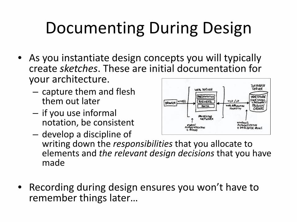
Documenting During Design• As you instantiate design concepts you will typically
create sketches. These are initial documentation for your architecture. – capture them and flesh
them out later– if you use informal
notation, be consistent– develop a discipline of
writing down the responsibilities that you allocate to elements and the relevant design decisions that you have made
• Recording during design ensures you won’t have to remember things later…

ADD: Iteration 1Design objectives Primary functional
requirementsQuality attribute
scenarios Constraints Concerns
Step 1: Review Inputs
Step 2: Establish iteration goal and select inputs to be considered in the iteration
Step 3: Choose one or more elements of the system to decompose
Step 4: Choose one or more design concepts that satisfy the inputs considered in the iteration
Step 5: Instantiate architectural elements, allocate responsibilities and define interfaces
Step 6: Sketch views and record design decisions
Step 7: Perform analysis of current design and review iteration goal and design objectives
Software architecture design
Input/output artifact
Process step
Step
8: R
efin
e as
nec
essa
ry
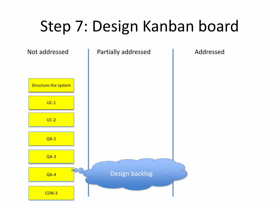
Step 7: Design Kanban boardNot addressed Partially addressed Addressed
Structure the system
UC-1
UC-2
QA-1
QA-3
QA-4 Design backlog
CON-3

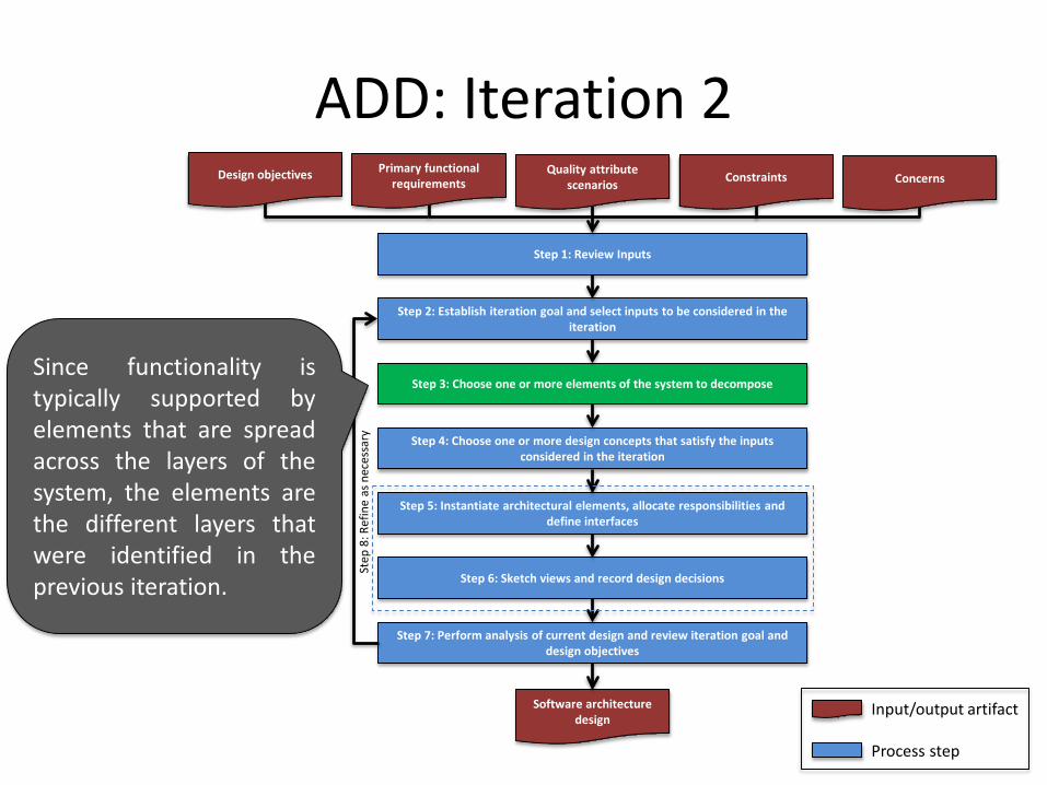
ADD: Iteration 2Design objectives Primary functional
requirementsQuality attribute
scenarios Constraints Concerns
Step 1: Review Inputs
Step 2: Establish iteration goal and select inputs to be considered in the iteration
Step 3: Choose one or more elements of the system to decompose
Step 4: Choose one or more design concepts that satisfy the inputs considered in the iteration
Step 5: Instantiate architectural elements, allocate responsibilities and define interfaces
Step 6: Sketch views and record design decisions
Step 7: Perform analysis of current design and review iteration goal and design objectives
Software architecture design
Input/output artifact
Process step
Step
8: R
efin
e as
nec
essa
ry
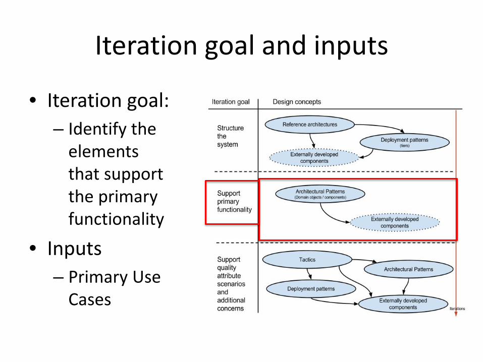
Iteration goal and inputs
• Iteration goal:– Identify the
elements that support the primary functionality
• Inputs– Primary Use
Cases
ADD: Iteration 2Design objectives Primary functional
requirementsQuality attribute
scenarios Constraints Concerns
Step 1: Review Inputs
Step 2: Establish iteration goal and select inputs to be considered in the iteration
Step 3: Choose one or more elements of the system to decompose
Step 4: Choose one or more design concepts that satisfy the inputs considered in the iteration
Step 5: Instantiate architectural elements, allocate responsibilities and define interfaces
Step 6: Sketch views and record design decisions
Step 7: Perform analysis of current design and review iteration goal and design objectives
Software architecture design
Input/output artifact
Process step
Step
8: R
efin
e as
nec
essa
rySince functionality istypically supported byelements that are spreadacross the layers of thesystem, the elements arethe different layers thatwere identified in theprevious iteration.

ADD: Iteration 2Design objectives Primary functional
requirementsQuality attribute
scenarios Constraints Concerns
Step 1: Review Inputs
Step 2: Establish iteration goal and select inputs to be considered in the iteration
Step 3: Choose one or more elements of the system to decompose
Step 4: Choose one or more design concepts that satisfy the inputs considered in the iteration
Step 5: Instantiate architectural elements, allocate responsibilities and define interfaces
Step 6: Sketch views and record design decisions
Step 7: Perform analysis of current design and review iteration goal and design objectives
Software architecture design
Input/output artifact
Process step
Step
8: R
efin
e as
nec
essa
ry
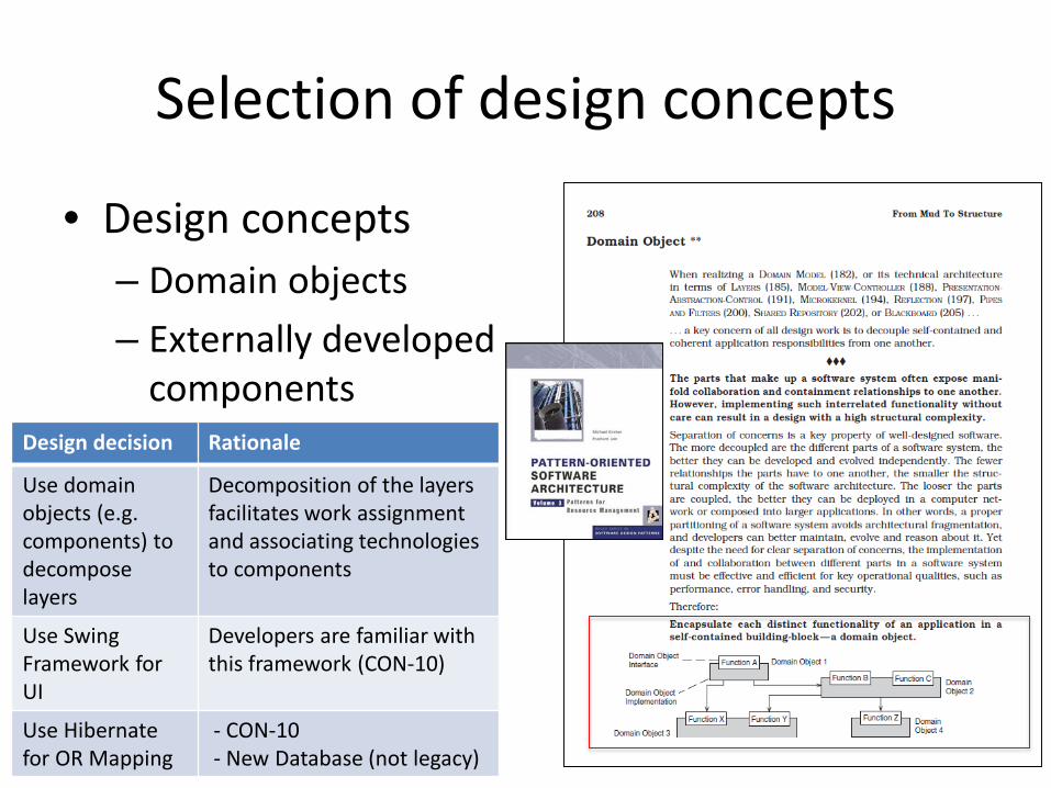
Selection of design concepts
• Design concepts– Domain objects– Externally developed
componentsDesign decision Rationale
Use domain objects (e.g. components) to decompose layers
Decomposition of the layers facilitates work assignment and associating technologies to components
Use Swing Framework for UI
Developers are familiar withthis framework (CON-10)
Use Hibernatefor OR Mapping
- CON-10- New Database (not legacy)
ADD: Iteration 2Design objectives Primary functional
requirementsQuality attribute
scenarios Constraints Concerns
Step 1: Review Inputs
Step 2: Establish iteration goal and select inputs to be considered in the iteration
Step 3: Choose one or more elements of the system to decompose
Step 4: Choose one or more design concepts that satisfy the inputs considered in the iteration
Step 5: Instantiate architectural elements, allocate responsibilities and define interfaces
Step 6: Sketch views and record design decisions
Step 7: Perform analysis of current design and review iteration goal and design objectives
Software architecture design
Input/output artifact
Process step
Step
8: R
efin
e as
nec
essa
ry
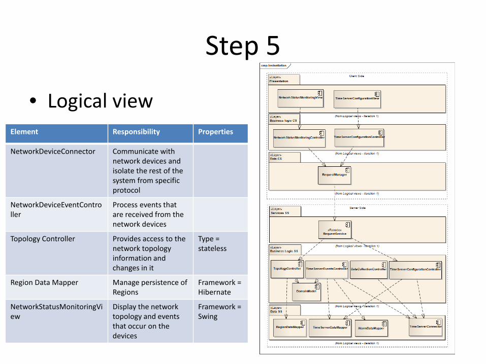
Step 5
• Logical viewElement Responsibility Properties
NetworkDeviceConnector Communicate with network devices and isolate the rest of the system from specific protocol
NetworkDeviceEventController
Process events that are received from the network devices
Topology Controller Provides access to the network topology information and changes in it
Type = stateless
Region Data Mapper Manage persistence of Regions
Framework = Hibernate
NetworkStatusMonitoringView
Display the network topology and events that occur on the devices
Framework =Swing
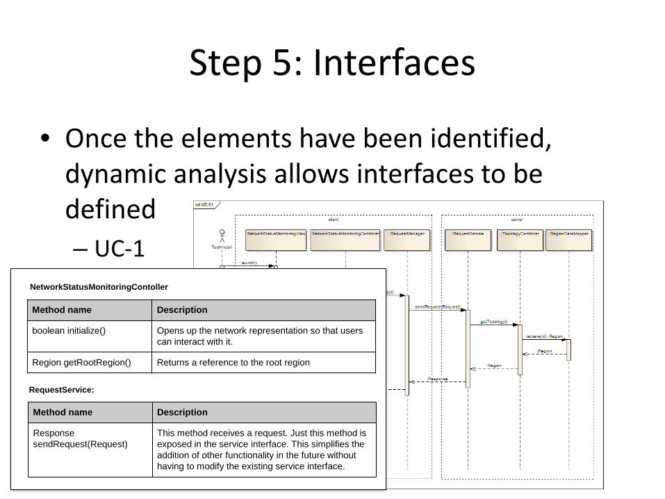
Step 5: Interfaces
• Once the elements have been identified, dynamic analysis allows interfaces to be defined– UC-1
NetworkStatusMonitoringContoller
RequestService:
Method name Description
boolean initialize() Opens up the network representation so that users can interact with it.
Region getRootRegion() Returns a reference to the root region
Method name Description
Response sendRequest(Request)
This method receives a request. Just this method is exposed in the service interface. This simplifies the addition of other functionality in the future without having to modify the existing service interface.
ADD: Iteration 2Design objectives Primary functional
requirementsQuality attribute
scenarios Constraints Concerns
Step 1: Review Inputs
Step 2: Establish iteration goal and select inputs to be considered in the iteration
Step 3: Choose one or more elements of the system to decompose
Step 4: Choose one or more design concepts that satisfy the inputs considered in the iteration
Step 5: Instantiate architectural elements, allocate responsibilities and define interfaces
Step 6: Sketch views and record design decisions
Step 7: Perform analysis of current design and review iteration goal and design objectives
Software architecture design
Input/output artifact
Process step
Step
8: R
efin
e as
nec
essa
ry
Step 7: Design Kanban boardNot addressed Partially addressed Addressed
Structure the system
UC-1
UC-2
QA-1
QA-3
QA-4
CON-3

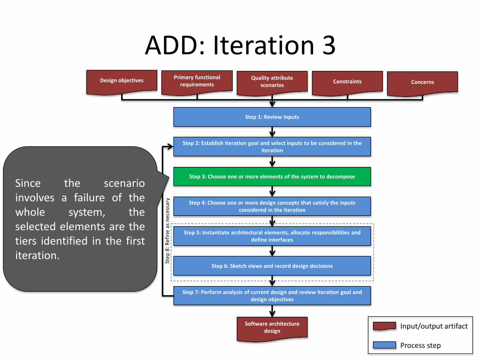
ADD: Iteration 3Design objectives Primary functional
requirementsQuality attribute
scenarios Constraints Concerns
Step 1: Review Inputs
Step 2: Establish iteration goal and select inputs to be considered in the iteration
Step 3: Choose one or more elements of the system to decompose
Step 4: Choose one or more design concepts that satisfy the inputs considered in the iteration
Step 5: Instantiate architectural elements, allocate responsibilities and define interfaces
Step 6: Sketch views and record design decisions
Step 7: Perform analysis of current design and review iteration goal and design objectives
Software architecture design
Input/output artifact
Process step
Step
8: R
efin
e as
nec
essa
ry
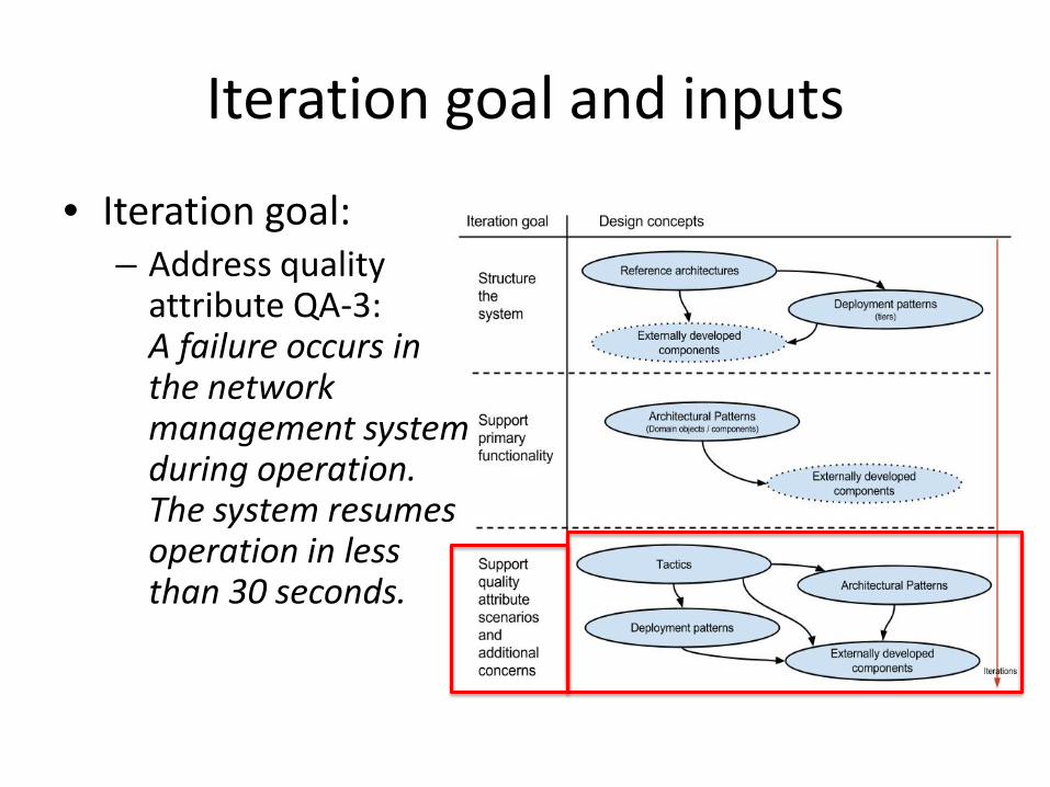
Iteration goal and inputs
• Iteration goal: – Address quality
attribute QA-3: A failure occurs in the network management system during operation. The system resumes operation in less than 30 seconds.
ADD: Iteration 3Design objectives Primary functional
requirementsQuality attribute
scenarios Constraints Concerns
Step 1: Review Inputs
Step 2: Establish iteration goal and select inputs to be considered in the iteration
Step 3: Choose one or more elements of the system to decompose
Step 4: Choose one or more design concepts that satisfy the inputs considered in the iteration
Step 5: Instantiate architectural elements, allocate responsibilities and define interfaces
Step 6: Sketch views and record design decisions
Step 7: Perform analysis of current design and review iteration goal and design objectives
Software architecture design
Input/output artifact
Process step
Step
8: R
efin
e as
nec
essa
ry
Since the scenarioinvolves a failure of thewhole system, theselected elements are thetiers identified in the firstiteration.

ADD: Iteration 3Design objectives Primary functional
requirementsQuality attribute
scenarios Constraints Concerns
Step 1: Review Inputs
Step 2: Establish iteration goal and select inputs to be considered in the iteration
Step 3: Choose one or more elements of the system to decompose
Step 4: Choose one or more design concepts that satisfy the inputs considered in the iteration
Step 5: Instantiate architectural elements, allocate responsibilities and define interfaces
Step 6: Sketch views and record design decisions
Step 7: Perform analysis of current design and review iteration goal and design objectives
Software architecture design
Input/output artifact
Process step
Step
8: R
efin
e as
nec
essa
ry
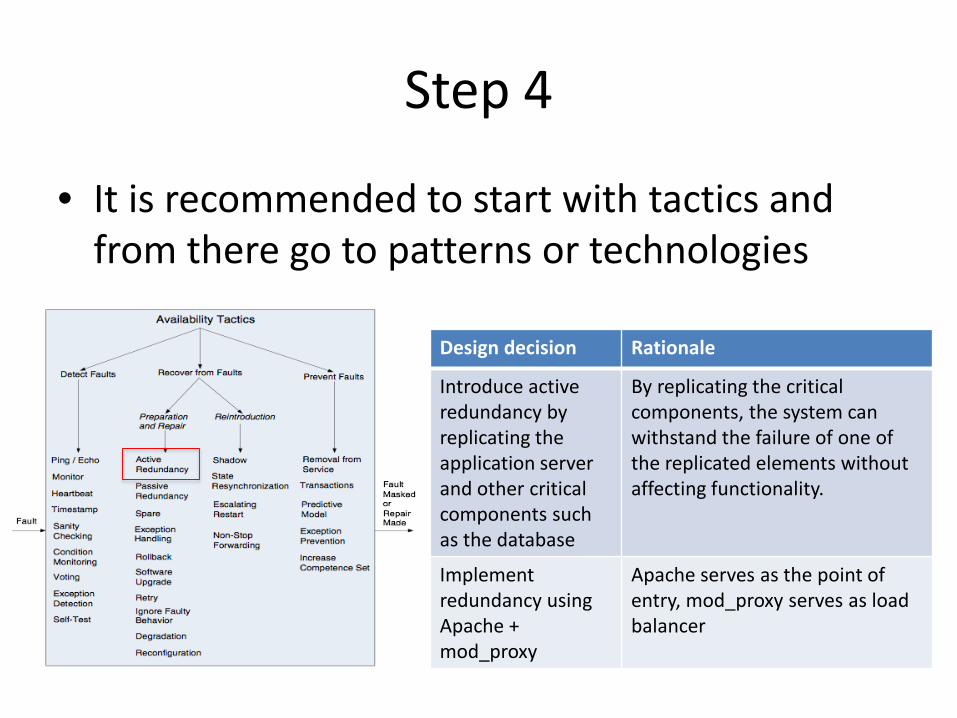
Step 4
• It is recommended to start with tactics and from there go to patterns or technologies
Design decision Rationale
Introduce active redundancy by replicating the application server and other critical components such as the database
By replicating the critical components, the system can withstand the failure of one of the replicated elements without affecting functionality.
Implement redundancy using Apache + mod_proxy
Apache serves as the point of entry, mod_proxy serves as load balancer

ADD: Iteration 3Design objectives Primary functional
requirementsQuality attribute
scenarios Constraints Concerns
Step 1: Review Inputs
Step 2: Establish iteration goal and select inputs to be considered in the iteration
Step 3: Choose one or more elements of the system to decompose
Step 4: Choose one or more design concepts that satisfy the inputs considered in the iteration
Step 5: Instantiate architectural elements, allocate responsibilities and define interfaces
Step 6: Sketch views and record design decisions
Step 7: Perform analysis of current design and review iteration goal and design objectives
Software architecture design
Input/output artifact
Process step
Step
8: R
efin
e as
nec
essa
ry
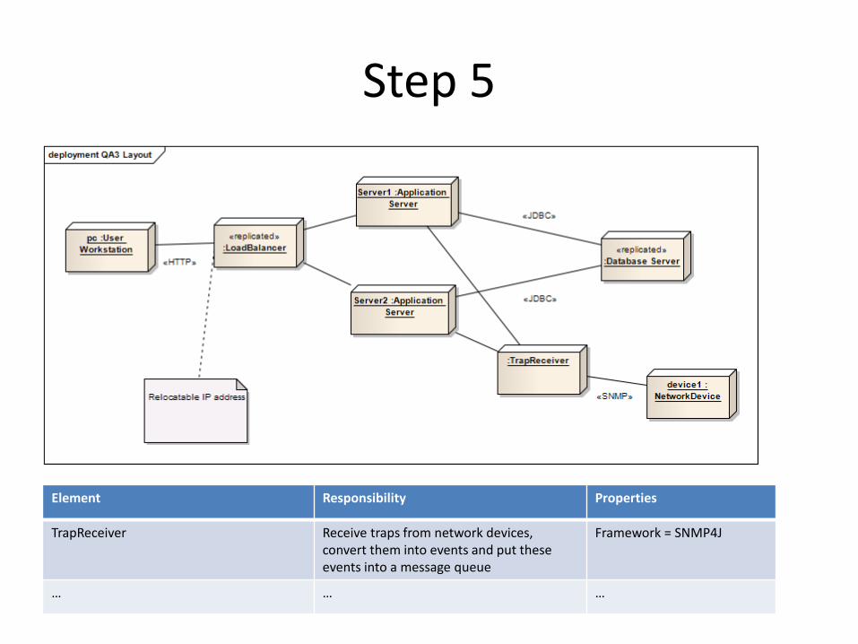
Step 5
Element Responsibility Properties
TrapReceiver Receive traps from network devices, convert them into events and put these events into a message queue
Framework = SNMP4J
… … …
ADD: Iteration 3Design objectives Primary functional
requirementsQuality attribute
scenarios Constraints Concerns
Step 1: Review Inputs
Step 2: Establish iteration goal and select inputs to be considered in the iteration
Step 3: Choose one or more elements of the system to decompose
Step 4: Choose one or more design concepts that satisfy the inputs considered in the iteration
Step 5: Instantiate architectural elements, allocate responsibilities and define interfaces
Step 6: Sketch views and record design decisions
Step 7: Perform analysis of current design and review iteration goal and design objectives
Software architecture design
Input/output artifact
Process step
Step
8: R
efin
e as
nec
essa
ry
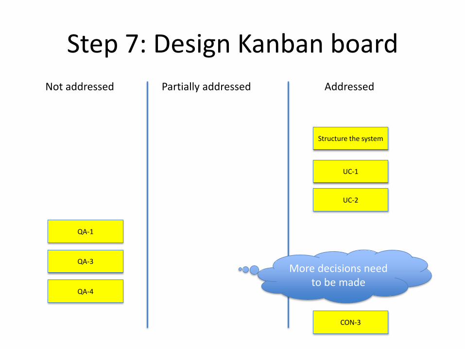
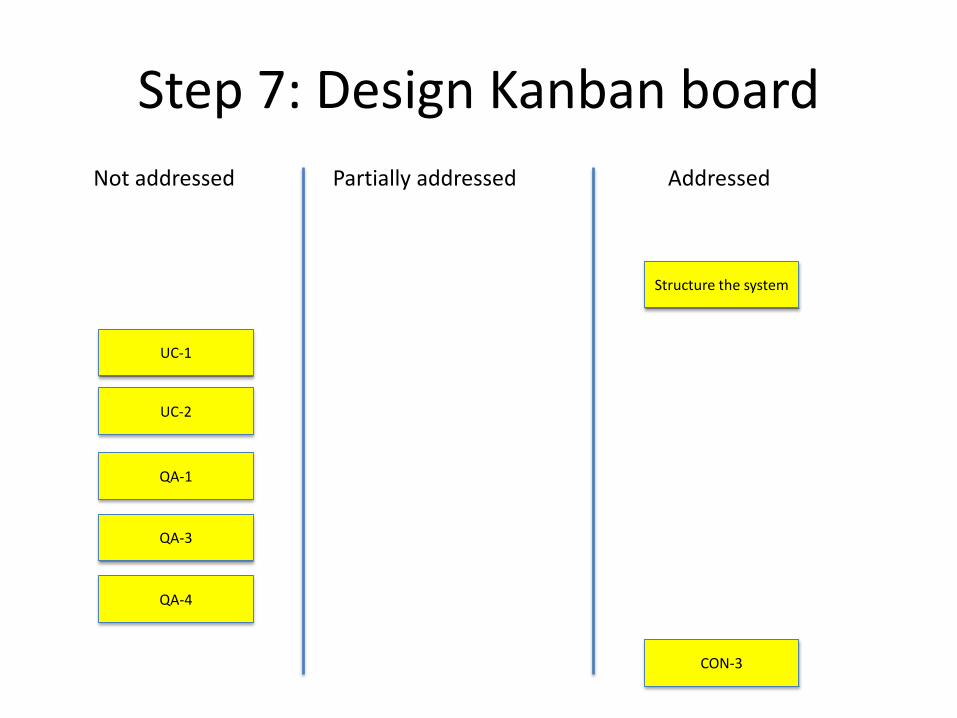
Step 7: Design Kanban boardNot addressed Partially addressed Addressed
Structure the system
UC-1
UC-2
QA-1
QA-3
QA-4
More decisions need to be made
CON-3
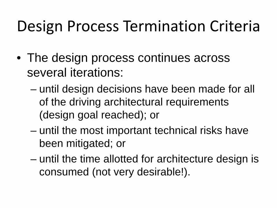
Design Process Termination Criteria
• The design process continues across several iterations:– until design decisions have been made for all
of the driving architectural requirements (design goal reached); or
– until the most important technical risks have been mitigated; or
– until the time allotted for architecture design is consumed (not very desirable!).
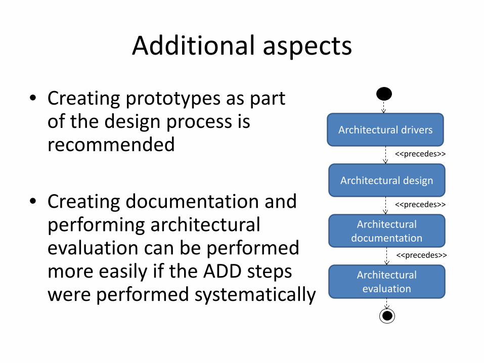
Additional aspects
• Creating prototypes as partof the design process isrecommended
• Creating documentation andperforming architecturalevaluation can be performedmore easily if the ADD stepswere performed systematically
Architectural drivers
Architectural design
Architectural documentation
Architectural evaluation
<<precedes>>
<<precedes>>
<<precedes>>
Summary• Architecture design transforms drivers into structures.• Architectural drivers include functional requirements,
quality attributes and constraints but also objectives, concerns and the type of system
• ADD is a method that structures architecture design so it may be performed systematically.
• Design concepts are building blocks from which the design is created. There are several important types: Reference Architectures, Deployment patterns, Architectural Patterns, Tactics, and Externally developed components such as frameworks.
• ADD can be performed in an agile way by using initial documentation (sketches) and a design kanban board to track design advancement

Thank you
• Questions?
• Rick Kazman [email protected]• Humberto Cervantes [email protected]
• Don’t miss the Smart Decisions: An Architecture Design Game session! (Wednesday, 11:00)
Recommended