Benjamin ChoiGlenn Research Center, Cleveland, Ohio
Jeffrey KauffmanPenn State University, University Park, Pennsylvania
Kirsten DuffyThe University of Toledo, Toledo, Ohio
Andrew Provenza and Carlos MorrisonGlenn Research Center, Cleveland, Ohio
Active Vibration Reduction of Titanium AlloyFan Blades (FAN1) Using Piezoelectric Materials
NASA/TM—2010-216335
May 2010
https://ntrs.nasa.gov/search.jsp?R=20100024330 2018-07-20T22:04:39+00:00Z

NASA STI Program . . . in Profi le
Since its founding, NASA has been dedicated to the advancement of aeronautics and space science. The NASA Scientifi c and Technical Information (STI) program plays a key part in helping NASA maintain this important role.
The NASA STI Program operates under the auspices of the Agency Chief Information Offi cer. It collects, organizes, provides for archiving, and disseminates NASA’s STI. The NASA STI program provides access to the NASA Aeronautics and Space Database and its public interface, the NASA Technical Reports Server, thus providing one of the largest collections of aeronautical and space science STI in the world. Results are published in both non-NASA channels and by NASA in the NASA STI Report Series, which includes the following report types: • TECHNICAL PUBLICATION. Reports of
completed research or a major signifi cant phase of research that present the results of NASA programs and include extensive data or theoretical analysis. Includes compilations of signifi cant scientifi c and technical data and information deemed to be of continuing reference value. NASA counterpart of peer-reviewed formal professional papers but has less stringent limitations on manuscript length and extent of graphic presentations.
• TECHNICAL MEMORANDUM. Scientifi c
and technical fi ndings that are preliminary or of specialized interest, e.g., quick release reports, working papers, and bibliographies that contain minimal annotation. Does not contain extensive analysis.
• CONTRACTOR REPORT. Scientifi c and
technical fi ndings by NASA-sponsored contractors and grantees.
• CONFERENCE PUBLICATION. Collected papers from scientifi c and technical conferences, symposia, seminars, or other meetings sponsored or cosponsored by NASA.
• SPECIAL PUBLICATION. Scientifi c,
technical, or historical information from NASA programs, projects, and missions, often concerned with subjects having substantial public interest.
• TECHNICAL TRANSLATION. English-
language translations of foreign scientifi c and technical material pertinent to NASA’s mission.
Specialized services also include creating custom thesauri, building customized databases, organizing and publishing research results.
For more information about the NASA STI program, see the following:
• Access the NASA STI program home page at http://www.sti.nasa.gov
• E-mail your question via the Internet to help@
sti.nasa.gov • Fax your question to the NASA STI Help Desk
at 443–757–5803 • Telephone the NASA STI Help Desk at 443–757–5802 • Write to:
NASA Center for AeroSpace Information (CASI) 7115 Standard Drive Hanover, MD 21076–1320

Benjamin ChoiGlenn Research Center, Cleveland, Ohio
Jeffrey KauffmanPenn State University, University Park, Pennsylvania
Kirsten DuffyThe University of Toledo, Toledo, Ohio
Andrew Provenza and Carlos MorrisonGlenn Research Center, Cleveland, Ohio
Active Vibration Reduction of Titanium AlloyFan Blades (FAN1) Using Piezoelectric Materials
NASA/TM—2010-216335
May 2010
National Aeronautics andSpace Administration
Glenn Research CenterCleveland, Ohio 44135
Prepared for the2010 Propulsion-Safety and Affordable Readiness (P–SAR) Conferencecosponsored by U.S. Army, Navy, and Air ForceJacksonville, Florida, March 16–18, 2010

Available from
NASA Center for Aerospace Information7115 Standard DriveHanover, MD 21076–1320
National Technical Information Service5301 Shawnee Road
Alexandria, VA 22312
Available electronically at http://gltrs.grc.nasa.gov
Trade names and trademarks are used in this report for identifi cation only. Their usage does not constitute an offi cial endorsement, either expressed or implied, by the National Aeronautics and
Space Administration.
This work was sponsored by the Fundamental Aeronautics Program at the NASA Glenn Research Center.
Level of Review: This material has been technically reviewed by technical management.
This report is a formal draft or working paper, intended to solicit comments and
ideas from a technical peer group.
This report contains preliminary fi ndings, subject to revision as analysis proceeds.

Active Vibration Reduction of Titanium Alloy Fan Blades (FAN1) Using Piezoelectric Materials
Benjamin Choi
National Aeronautics and Space Administration Glenn Research Center Cleveland, Ohio 44135
Jeffrey Kauffman
Penn State University University Park, Pennsylvania 16802
Kirsten Duffy
The University of Toledo Toledo, Ohio 43606
Andrew Provenza and Carlos Morrison
National Aeronautics and Space Administration Glenn Research Center Cleveland, Ohio 44135
Abstract
The NASA Glenn Research Center is developing smart adaptive structures to improve fan blade damping at resonances using piezoelectric (PE) transducers. In this paper, a digital resonant control technique emulating passive shunt circuits is used to demonstrate vibration reduction of FAN1 Ti real fan blade at the several target modes. Single-mode control and multi-mode control using one piezoelectric material are demonstrated. Also a conceptual study of how to implement this digital control system into the rotating fan blade is discussed.
NASA/TM—2010-216335 1
National Aeronautics and Space Administration
Objective
Investigate possibility of using an active resonance controller for turbomachinery blade with piezoelectric sensors/actuators.
I. IntroductionII. Shunt damping and digital control designIII. Experimental test resultsIV. Summary
Outline
2010 P-SAR Conference, March 16-18, Jacksonville, FL Cold Section Durability
National Aeronautics and Space Administration
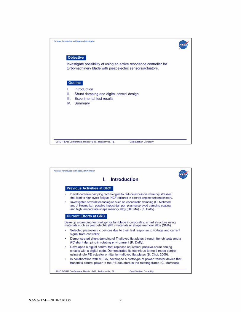
Previous Activities at GRC
I. Introduction
• Developed new damping technologies to reduce excessive vibratory stresses that lead to high cycle fatigue (HCF) failures in aircraft engine turbomachinery.
• Investigated several technologies such as viscoelastic damping (O. Mehmed est gated se e a tec o og es suc as scoe ast c da p g (O e edand J. Kosmatka), passive impact damper, plasma sprayed damping coating, and high temperature shape memory alloy (HTSMA) - (K. Duffy).
• Selected piezoelectric devices due to their fast response to voltage and current signal from controller.
• Demonstrated shunt damping of Ti alloyed flat plates through bench tests and a
Current Efforts at GRC
Develop a damping technology for fan blade incorporating smart structure using materials such as piezoelectric (PE) materials or shape memory alloy (SMA).
• Demonstrated shunt damping of Ti-alloyed flat plates through bench tests and a RC shunt damping in rotating environment (K. Duffy).
• Developed a digital control that replaces equivalent passive-shunt analog circuits with a digital code. Demonstrated its technique to multi-mode control using single PE actuator on titanium-alloyed flat plates (B. Choi, 2009).
• In collaboration with MESA, developed a prototype of power transfer device that transmits control power to the PE actuators in the rotating frame (C. Morrison).
2010 P-SAR Conference, March 16-18, Jacksonville, FL Cold Section Durability
NASA/TM—2010-216335 2

National Aeronautics and Space Administration
Smart Fan Blade Technology Pros and Cons
Benefits/Payoffs: support the NASA missions- Thinner and more efficient blades with shunt damping – fuel burn reduction noise reduction HCF failure reduction etc
I. Introduction (continued)
reduction, noise reduction, HCF failure reduction, etc.- Actively controlled blades - real-time health monitoring, aeroelastic control, mistuning problem, active fan distortion control for distributed propulsion system, etc.
Drawbacks: structural characteristics degradation, durability and safety issues, added electronics weights, etc.- S. Mall (2002) investigated the integrity of the embedded active PZT sensor/actuator under monotonic and fatigue loads – no degradation seen in experimental tests.
R Pickering and K Barlow (2007) specified the duration (10e+07 cycles)- R. Pickering and K. Barlow (2007) specified the duration (10e+07 cycles) for each vibration mode for durability spin test according to the Goodman diagram.- Completed a preliminary durability bench test for 109 cycles under 4.6g at target frequency. Need retest at high speed rotor. - On-going system trade study of blade weights reduction vs. added electronics weights.
2010 P-SAR Conference, March 16-18, Jacksonville, FL Cold Section Durability
National Aeronautics and Space Administration
Analog Shunt Circuits for Turbomachinery Blades1.
Literature Survey for Recent Advances
• Passive control of turbomachine blading flow-induced vibrations (C. Cross, 2002).
- Synthetic inductor replacing L = 342 H controlled the first bending mode – real challenge.
• Passive shunt circuit was tested for piezoblade damping (S. Livet, 2008).
- Virtual inductor (or “gyrator”) that consists of op amps, resistors, capacitors, and ext.Virtual inductor (or gyrator ) that consists of op amps, resistors, capacitors, and ext. power supply.
• Numerous papers published for passive shunt for rotorcraft vibration.
2. Active Control of PE Actuator for Turbomachinery Blades• Cascade flutter control using PE device in subsonic flow (T. Watanabe, 2005).
- Trailing edge of non-rotating airfoil was oscillated by PE to control the passage shock.
• Low-speed fan noise control using PE actuators mounted on stator vanes (P. Remington, 2003). Reduced fan-stator interaction noise using 210 vane actuators.
2010 P-SAR Conference, March 16-18, Jacksonville, FL Cold Section Durability
Full-scale helicopter smart bladein a Ames Res. Ctr. wind tunnel
• Force excitation control using surface-mounted PE patches on the rotating blades (I. Santos, 2009).
- First demo in the spin pit. Used Thunder flexible patches covering full blade surfaces.
• NASA Ames/Boeing developed shape-shifting helicopter blades (2009). PE actuators created a mechanical motion that moves a flap up and down.
NASA/TM—2010-216335 3
National Aeronautics and Space Administration
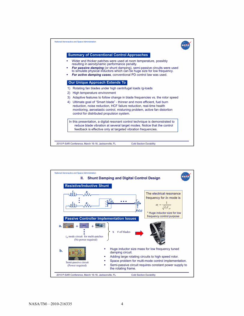
Summary of Conventional Control Approaches
Wider and thicker patches were used at room temperature, possibly resulting in aerodynamic performance penalty.
For passive damping (or shunt damping), semi-passive circuits were used to simulate physical inductors which can be huge size for low frequency.
For active damping cases conventional PD control law was used
Our Unique Approach Extends To
For active damping cases, conventional PD control law was used.
1) Rotating fan blades under high centrifugal loads /g-loads
2) High temperature environment
3) Adaptive features to follow change in blade frequencies vs. the rotor speed
4) Ultimate goal of “Smart blade” - thinner and more efficient, fuel burn reduction, noise reduction, HCF failure reduction, real-time health monitoring aeroelastic control mistuning problem active fan distortionmonitoring, aeroelastic control, mistuning problem, active fan distortion control for distributed propulsion system.
2010 P-SAR Conference, March 16-18, Jacksonville, FL Cold Section Durability
In this presentation, a digital resonant control technique is demonstrated to reduce blade vibration at several target modes. Notice that the control feedback is effective only at targeted vibration frequencies.
National Aeronautics and Space Administration
II. Shunt Damping and Digital Control Design
L1 R1
Resistive/Inductive Shunt
i
1
The electrical resonance frequency for ith mode is
Cp1
Li Ri
Cpi
f(d,t)pii
iCL
Passive Controller Implementation Issues
+
ith mode circuit for multi-patches
x # of blades
+
* Huge inductor size for low frequency control purpose
(No power required)
a.
2010 P-SAR Conference, March 16-18, Jacksonville, FL Cold Section Durability
Semi-passive circuit
b.
(Power required)
Huge inductor size mass for low frequency tuned damping circuit.
Adding large rotating circuits to high speed rotor. Space problem for multi-mode control implementation. Semi-passive circuit requires constant power supply to
the rotating frame.
NASA/TM—2010-216335 4

National Aeronautics and Space Administration
Digital Control Approach
Transfer function of LRC shunt circuit is expressed in S-domain so that it can be programmed in a digital code.
As opposed to analog shunt circuit a real-time adaptive control for
Digital Control Design
As opposed to analog shunt circuit, a real time adaptive control for change in blade frequencies in Campbell Diagram is possible.
Adaptive capability to aged blade dynamics change is possible.
Effective for multi-mode control because a few coding lines are necessary, as opposed to analog circuit approach.
Control feedback is effective only at targeted blade frequencies.
Digital Controller Implementation Issues
Added weights of power electronics in the rotating frame. Durable power electronics surviving high centrifugal loads/g-loads. Operational overhead of transducing high voltage power to the blades. Potential cross-talk between high voltage control signals and blade
sensor signals. Safety and durability issues of power electronics, etc.
2010 P-SAR Conference, March 16-18, Jacksonville, FL Cold Section Durability
National Aeronautics and Space Administration
LiRZ o
)/( CiLiRZ i
Transfer Function of Analog LRC Circuit
C
Digital Control Design (continued)
General feedback control LRC network.
Zo outputZi input
1
)(
)/(
2
CRsLCs
LsRCs
CiLiR
LiR
Z
Z
V
V
i
o
i
o
The controller is expressed in terms of passive circuit components (LRC) regardless of modal shape
L
R
shape.
Kp: proportional gain, Ki: integral gain, Kd: derivative gain
PID (proportional-integral-derivative) Control Law
2010 P-SAR Conference, March 16-18, Jacksonville, FL Cold Section Durability
NASA/TM—2010-216335 5
National Aeronautics and Space Administration
)()()()( sVsVsAsV isia
The actuator voltage Va(s) is
where Ai(s) is ΣVs(s)
F(d, s)
Va(s)Vi(s) +Gvv(s) Σ
++
Gfv(s)
Digital Control Design (continued)
1
)()(
2
sCRCsL
sLRCssA
ii
iii
-
Feedback control block diagram for blade structure with PEs.
The Closed-loop System Transfer Functions
∑Ai(s)
A set of control laws in parallel circuits can be summed to control several modes (B. Choi, 2009).
)()(1
)(),(
)()(1
),(),(),(
sGsA
sVsrG
sGsA
sdFsrGsrY
vv
ivy
vv
fy
)()(1
)()(
)()(1
),()()(
sGsA
sVsG
sGsA
sdFsGsV
vv
ivv
vv
fvs
)(
),()(,
),(
),(),(
)(
)()(,
),(
)()(
sV
srYsG
sdF
srYsrG
sV
sVsG
sdF
sVsG
avyfy
a
svv
afv
where
2010 P-SAR Conference, March 16-18, Jacksonville, FL Cold Section Durability
National Aeronautics and Space Administration
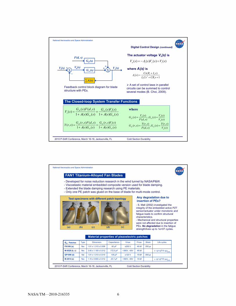
- Developed for noise reduction research in the wind tunnel by NASA/P&W.- Viscoelastic material embedded composite version used for blade damping. - Extended the blade damping research using PE materials.- Only one PE patch was glued on the base of blade for multi-mode control.
Test specimens with different patch topology Any degradation due to
FAN1 Titanium-Alloyed Fan Blades
(e)(a) (b) (c) (d)
Test specimens with different patch topologyinsertion of PEs?- S. Mall (2002) investigated the integrity of the embedded active PZT sensor/actuator under monotonic and fatigue loads to confirm structural characteristics.- Mechanical and structural properties were not affected due to insertion of PEs. No degradation in the fatigue strength/lives up to 1e+07 cycles.
2010 P-SAR Conference, March 16-18, Jacksonville, FL Cold Section Durability
d31 Patches Type Dimension Capacitance Vmax Fmax Strain Life cycles
PA16N (a) flex 1.81 x 1.310 x 0.006 60 μF ±200 V 46 lbf 550 με
M-8528 (b, c) flex 3.40 x 1.100 x 0.012 172.0 μF +360V, -60V 46 lbf > 10*109 @ 1kVp-p
QP10W (d) flat 1.81 x 1.310 x 0.010 105 μF ±120 V 15 lbf 500 με
M-2814 (e) flex 1.10 x 0.600 x 0.012 25.7 μF +360V, -60V 19 lbf > 10*109 @ 1kVp-p
Material properties of piezoelectric patches
NASA/TM—2010-216335 6

National Aeronautics and Space Administration
Experimental Test Setup
Power ampsdSPACEcontroller
Voltage amplifierLP Filter
III. Experimental Test Results
One actuating PE patch actuation was bonded at the near root side and one accelerometer at the tip for feedback sensing for the target resonances – 1st and 2nd
bending 2nd torsion modes in this test
Experimental setup for FAN1 blade
Shaker
Laser vib.
Acc.Vs(s)
ΣVi(s) +
ΣAi(s)
-
dSPACE control system
Shaker
Inductors
bending, 2 torsion modes in this test.
After fine-tuning the controller to the experimental target resonances, downloaded the control algorithm to the dSPACE control system.
HP Analyzer generated swept sine signal to send to the shaker, and it read all signals from accelerometers, and command signal to PE actuator as well as controller voltage and current from the power amplifier.
Analyzed open- and closed-loop transfer functions to investigate achieved damping performance for each target mode.
2010 P-SAR Conference, March 16-18, Jacksonville, FL Cold Section Durability
National Aeronautics and Space Administration
1.a) Passive Shunt for 2nd Torsion (478 Hz) and 2nd Bending (907 Hz) Modes
QP10W act ator
Acc.
0 51H ind ctors for 907 H
Experimental Test Results (continued)
5.0
50.0
Ma
gn
itu
de
Transfer function of tip acceleration using passive LRC circuits
Baseline of Acc_t1.86H (1.85H_theo)0.56H (0.51H_theo)0.51H (0.51H_theo)
478 Hz
(2T)
907 Hz
(2B)
1st mode tuned 15% 51%
2nd mode tuned 18% 73%
Peak Reduction at Target Modes
QP10W actuator 0.51H inductors for 907 Hz1.86H inductors for 478 Hz
2010 P-SAR Conference, March 16-18, Jacksonville, FL Cold Section Durability
0.5
400 500 600 700 800 900 1000Hz
For the 1st tuned circuit, several inductors in serial and parallel series were used. But high resistor value made controller peak flat – less peak reduction. Thus, low resistance valued inductors are required for better performance.Bode plots of Tf |atip/fbase| for LRC shunt circuits.
NASA/TM—2010-216335 7

National Aeronautics and Space Administration
Comparison of Passive Shunt and Active Control Performance
50.0
Tf of tip acc. using passive shunt (R=475) and active control (R=500)
Baseline of Acc_t0.51H (0.51H theo)
Bode plots of Tf |atip/fbase| for LRC shunt circuit and active controller
0.5
5.0
400 500 600 700 800 900 1000
Mag
nit
ud
e
Hz
( _ )Gain=[0, -10], R=500
Passive shunt circuit
Active controller
1
)()(
2
sCRCsL
sLRCssA
ii
ii
Transfer function of feedback
2010 P-SAR Conference, March 16-18, Jacksonville, FL Cold Section Durability
circuit and active controller.
The measured resistor value of passive shunt circuit was about 475 Ω. An active controller with R=500 Ω shows nearly same bandwidth as the passive shunt has.
This demonstrated that the passive shunt can be programmed into digital code to perform flawlessly.
digital control
National Aeronautics and Space Administration
1.b) Active Control for 478 Hz (2T) and 907 Hz (2B)
QP10w actuator
Acc. sensor
- QP10w Actuator and Tip Acc. Sensor (R=250)
Transfer function of tip acc. Transfer function of tip acc.
Single-Mode Control Multi-Mode Control
T |a /f | at 478 Hz and 907 Hz
1
5
50
400 500 600 700 800 900 1000
Mag
nit
ud
e
Hz
with R= 250
Baseline of Acc_tGain=[0, -25]Gain=[0, -15]
1
5
50
400 500 600 700 800 900 1000
Mag
nit
ud
e
Hz
pwith R=250
Baseline of Acc_tGain=[-25, 0]Gain=[-12, -12]
2010 P-SAR Conference, March 16-18, Jacksonville, FL Cold Section Durability
Tf |atip/fbase| at 478 Hz and 907 Hz
R=250 478 Hz 907 Hz
Cont. Gain = [0, 25] 15% 72%
Cont. Gain = [0, 15] 7% 71%
Large R values (wide bandwidth) can reduce side peaks for better performance.
Tf |atip/fbase| at 478 Hz and 907 Hz
R=250 478 Hz 907 Hz
Cont. Gain = [25, 0] 63% -41%
Cont. Gain = [12, 12] 60% 64%
Notice that multi-control using one PE works for 2T and 2B - different mode types.
NASA/TM—2010-216335 8

National Aeronautics and Space Administration
50.0
Transfer function of tip acc.with R=250, 500
Baseline of Acc_tGain=[0, -25], R=250Gain=[0 -15] R=250
5.00
Experimental Tf of active controller with R= 250
Gain=[-12, -12]Gain=[-25, 0]
1st mode tuned
2nd mode tuned
Active Controllers with R=250 and 500 Experimental Tf of Active Controllers
Investigate How R Affects The Performance
0.5
5.0
400 500 600 700 800 900 1000
Mag
nit
ud
e
Hz
Gain=[0, -15], R=250Gain=[0, -10], R=500Gain=[+12, 0], R=500
478 Hz 907 Hz
Peak Reduction at Target Modes
0.05
0.50
400 500 600 700 800 900 1000
Mag
nit
ud
e
Hz
Gain=[0, -25]multi-mode
Ideal modes 478 Hz 907 Hz
Ideal and Experimental Modes
2010 P-SAR Conference, March 16-18, Jacksonville, FL Cold Section Durability
Larger R value reduced side peaks.
Cont. Gain [0, 25], R=250 15% 72%
Cont. Gain [0, 15], R=250 7% 71%
Cont. Gain [0, 10], R=500 15% 76%
Cont. Gain [12, 0], R=500 63% 73%
1st mode tuned 477 Hz –
2nd mode tuned – 911 Hz
Multi-mode 475 Hz 914 Hz
Good match between ideal and experimental target frequencies, but fine-tuned controller is a must for lower frequency.
National Aeronautics and Space Administration
1V*sin(478Hz*t) injected
0.1
0.3
0.5
0.7
ud
e, m
ils
Uncontrolled tip displacement
Gain=[0, 0], Tip_top
Gain=[0, 0], Tip-bot
Time History of Tip Displacements at 478 Hz (2T) and 907 Hz (2B)
0 0
0.1
0.2
de,
mils
Uncontrolled tip displacement
Gain=[0, 0], Tip_top
Gain=[0, 0], Tip-bot
1V*sin(907Hz*t) injected
-0.7
-0.5
-0.3
-0.1
0.000 0.005 0.010 0.015
Am
plit
u
Time, sec
-0.3
-0.1
0.1
0.3
0.5
0.7
Am
plit
ud
e, m
ils
Controlled tip displacement
Gain=[-25, 0], Tip_top
Gain=[-25, 0], Tip-bot
-0.2
-0.1
0.0
0.000 0.005 0.010 0.015
Am
plit
ud
Time, sec
0 1
0.0
0.1
0.2
Am
plit
ud
e, m
ils
Controlled tip displacement
Gain=[0, -25], Tip_top
Gain=[0, -25], Tip-bot
Baseline Baseline Acc.
sensor
2010 P-SAR Conference, March 16-18, Jacksonville, FL Cold Section Durability
Shows time history of controlled and uncontrolled tip displacement when excitation force at torsion mode (478 Hz) was applied. See signals in out of phase.
As anticipated, about 80% tip reduction achieved.
-0.7
-0.5
0.000 0.005 0.010 0.015
A
Time, sec
-0.2
-0.1
0.000 0.005 0.010 0.015
A
Time, sec
Actively controlled Actively controlled
Shows time history of tip displacement when excitation force at bending mode (907 Hz) was applied. See signals in phase.
As anticipated, about 80% tip reduction achieved.
NASA/TM—2010-216335 9
National Aeronautics and Space Administration
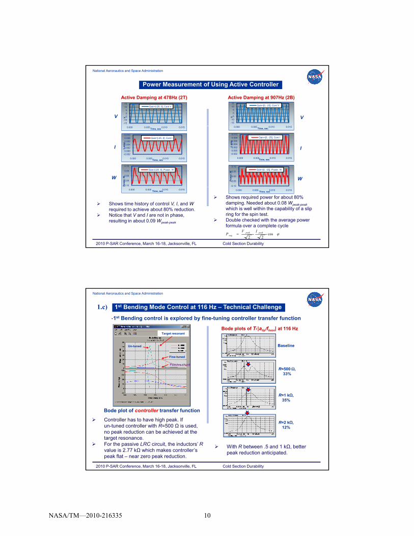
Power Measurement of Using Active Controller
Active Damping at 478Hz (2T)
-15-10-505
1015
V
Gain=[-25, 0], Cont V
-15-10-505
1015
0 000 0 00 0 010 0 01
V
Gain=[0, -25], Cont V
V V
Active Damping at 907Hz (2B)
0.000 0.005 0.010 0.015Time, sec
-0.0020.0000.0020.0040.0060.0080.010
0.000 0.005 0.010 0.015
I, am
p
Time, sec
Gain=[-25, 0], Cont I
-0.10
-0.05
0.00
0.05
0.10
Po
wer
, W
Gain=[-25, 0], Power, W
0.000 0.005 0.010 0.015Time, sec
-0.0020.0000.0020.0040.0060.0080.010
0.000 0.005 0.010 0.015
I, am
p
Time, sec
Gain=[0, -25], Cont I
-0.10
-0.05
0.00
0.05
0.10
Po
wer
, W
Gain=[0, -25], Power, W
I
W
I
W
cos22
peakpeakavg
IVP
2010 P-SAR Conference, March 16-18, Jacksonville, FL Cold Section Durability
0.000 0.005 0.010 0.015Time, sec 0.000 0.005 0.010 0.015
Time, sec
Shows time history of control V, I, and Wrequired to achieve about 80% reduction.
Notice that V and I are not in phase, resulting in about 0.09 Wpeak-peak
Shows required power for about 80% damping. Needed about 0.08 Wpeak-peak
which is well within the capability of a slip ring for the spin test.
Double checked with the average power formula over a complete cycle
National Aeronautics and Space Administration
1st Bending Mode Control at 116 Hz – Technical Challenge
Target resonant
Un-tuned
Bode plots of Tf |atip/fbase| at 116 Hz
Baseline
1.c)
-1st Bending control is explored by fine-tuning controller transfer function
Fine-tuned
Passive shunt
R=500 Ω, 33%
R=1 kΩ, 35%
Bode plot of controller transfer function
2010 P-SAR Conference, March 16-18, Jacksonville, FL Cold Section Durability
Controller has to have high peak. If un-tuned controller with R=500 Ω is used, no peak reduction can be achieved at the target resonance.
For the passive LRC circuit, the inductors’ Rvalue is 2.77 kΩ which makes controller’s peak flat – near zero peak reduction.
R=2 kΩ, 12%
With R between .5 and 1 kΩ, better peak reduction anticipated.
Bode plot of controller transfer function
NASA/TM—2010-216335 10

National Aeronautics and Space Administration
Flexible Patch Performance at 947 Hz (2B)
- PA16N flexible patch used for actuator. Two different feedback sensing signals from tip acc. and QP10W patch at near base of blade.
1.d)
PA16N actuatorAcc.
sensor
PA16N actuator
QP10W sensor
1.0
3.0
5.0
7.0
9.0
800 850 900 950 1000Hz
Tfof tip acceleration
baseline
R=300
0.0
0.3
0.6
0.9
1.2
1.5
800 850 900 950 1000
Magnitude
Hz
Tf of PE at near base side
baselineR=300
Bode plot of Tf |atip/fbase| with R=300 Bode plot of Tf |PEroot/fbase| with R=300
2010 P-SAR Conference, March 16-18, Jacksonville, FL Cold Section Durability
Uncontrolled Controlled
PE_r
Acc_t
Uncontrolled Controlled
| tip fbase| | root fbase|
National Aeronautics and Space Administration
Spin Test in Dynamic Spin Rig
Trapezoidal blade
- Currently fabrication of a canister is in progress to modify spin facility to incorporate slip ring.- Completed bench test on the slip ring to investigate any cross talk, signal loss, phase lag, etc.- Confirmed power limit of each channel of the slip ring.
Spin test in NASA Dynamic Spin Rig
100Transfer function of tip acc.
Damping at two target modes
Slip ring for spin test
Bench test setup using LC circuit
next step
Signal loss thru slip ring when applied ±Vp-p
2010 P-SAR Conference, March 16-18, Jacksonville, FL Cold Section Durability
Bode plots of Tf |atip/fbase| for LC circuit
0
1
10
600 650 700 750 800 850
Magnitude
Hz
Baseline of Acc_t0.8H w/o slip ring0.8H w/ slip ring
637 Hz 760Hz
Signal loss thru slip ring
3.4% 4%
with 1st mode tuned circuit
0%
4%
8%
12%
16%
0 20 40 60 80 100
when applied ±Vp p
Vp-p
Less than 1.3% signal loss if Vinput > ±50V
NASA/TM—2010-216335 11

National Aeronautics and Space Administration
How To Implement Digital Control On The Rotating Fan Blades
PE
Op-Amp 1
± 200 VDC50 mAStationary frame
Control laws
D/A
Telemetry system
(option)
Op-Amp n
Power supply
Health monitoring
(option)
Wireless transfer (option)
Sensor signal
50 mA
Rotating frame
Stationary frameA/D
pp y
Photo courtesy of Datatel Telemetry Inductively powered transmitter
Photo courtesy of Datatel TelemetryNASA GRC/MESA prototype
control board w/ telemetry sys y ycontrol board w/ telemetry sys
Contains 8 inputs and 8 outputs, 8 Op-Amps (±200VDC @ 50mA), transmitter, and receiver. D/A card weighs about 0.3 lbs excluding its heat sink & supporting Aluminum block (0.2 lbs). A/D card weighs little less than 0.3 lbs.
Adding more features into the controller block, its application will be further extended to health monitoring, aeroelastic control, mistuning problem, etc.
Time lag of 1.5ms each path across the gap (“latency” in wireless transfer) makes difficult to move the controller to the stationary frame for the spin test purpose.
NASA GRC/MESA Control and Telemetry System
2010 P-SAR Conference, March 16-18, Jacksonville, FL Cold Section Durability
National Aeronautics and Space Administration
Demonstrated that the passive shunt can be viewed as a feedback control problem and thus a digital control that replaces analog circuit components can be developed.
Demonstrated a multi-mode digital controller using single actuator, adding a couple lines in digital code Unrealizable for analog shunt
VI. Summary
adding a couple lines in digital code. Unrealizable for analog shunt. Achieved significant peak reduction at the target modes with different
mode types. Presented conceptual implementation of digital control to the rotating
frame.
Future work
Complete dynamic spin test of PE embedded blades in the GRC’s Dynamic Spin Rig.
2010 P-SAR Conference, March 16-18, Jacksonville, FL Cold Section Durability
Further comprehensive system-leveled trade-off study must be done to prove a viable means of using this approach for the rotating blades.
NASA/TM—2010-216335 12

REPORT DOCUMENTATION PAGE Form Approved
OMB No. 0704-0188 The public reporting burden for this collection of information is estimated to average 1 hour per response, including the time for reviewing instructions, searching existing data sources, gathering and maintaining the data needed, and completing and reviewing the collection of information. Send comments regarding this burden estimate or any other aspect of this collection of information, including suggestions for reducing this burden, to Department of Defense, Washington Headquarters Services, Directorate for Information Operations and Reports (0704-0188), 1215 Jefferson Davis Highway, Suite 1204, Arlington, VA 22202-4302. Respondents should be aware that notwithstanding any other provision of law, no person shall be subject to any penalty for failing to comply with a collection of information if it does not display a currently valid OMB control number. PLEASE DO NOT RETURN YOUR FORM TO THE ABOVE ADDRESS.
1. REPORT DATE (DD-MM-YYYY) 01-05-2010
2. REPORT TYPE Technical Memorandum
3. DATES COVERED (From - To)
4. TITLE AND SUBTITLE Active Vibration Reduction of Titanium Alloy Fan Blades (FAN1) Using Piezoelectric Materials
5a. CONTRACT NUMBER
5b. GRANT NUMBER
5c. PROGRAM ELEMENT NUMBER
6. AUTHOR(S) Choi, Benjamin; Kauffman, Jeffrey; Duffy, Kirsten; Provenza, Andrew; Morrison, Carlos
5d. PROJECT NUMBER
5e. TASK NUMBER
5f. WORK UNIT NUMBER WBS 561581.02.08.03.15.13
7. PERFORMING ORGANIZATION NAME(S) AND ADDRESS(ES) National Aeronautics and Space Administration John H. Glenn Research Center at Lewis Field Cleveland, Ohio 44135-3191
8. PERFORMING ORGANIZATION REPORT NUMBER E-17270
9. SPONSORING/MONITORING AGENCY NAME(S) AND ADDRESS(ES) National Aeronautics and Space Administration Washington, DC 20546-0001
10. SPONSORING/MONITOR'S ACRONYM(S) NASA
11. SPONSORING/MONITORING REPORT NUMBER NASA/TM-2010-216335
12. DISTRIBUTION/AVAILABILITY STATEMENT Unclassified-Unlimited Subject Categories: 05 and 07 Available electronically at http://gltrs.grc.nasa.gov This publication is available from the NASA Center for AeroSpace Information, 443-757-5802
13. SUPPLEMENTARY NOTES
14. ABSTRACT The NASA Glenn Research Center is developing smart adaptive structures to improve fan blade damping at resonances using piezoelectric (PE) transducers. In this paper, a digital resonant control technique emulating passive shunt circuits is used to demonstrate vibration reduction of FAN1 Ti real fan blade at the several target modes. Single-mode control and multi-mode control using one piezoelectric material are demonstrated. Also a conceptual study of how to implement this digital control system into the rotating fan blade is discussed.15. SUBJECT TERMS Piezoelectric transducer; Active control; Damping tests; Fan blades; Vibration damping; Shunt damping
16. SECURITY CLASSIFICATION OF: 17. LIMITATION OF ABSTRACT UU
18. NUMBER OF PAGES
18
19a. NAME OF RESPONSIBLE PERSON STI Help Desk (email:[email protected])
a. REPORT U
b. ABSTRACT U
c. THIS PAGE U
19b. TELEPHONE NUMBER (include area code) 443-757-5802
Standard Form 298 (Rev. 8-98)Prescribed by ANSI Std. Z39-18


Recommended


![Near-Net-Shape Production of Hollow Titanium Alloy ... · titanium and titanium alloy components rather than the development of new alloys with enhanced properties.[9] The results](https://img.pdfslide.us/doc/110x75/602cb612dd533f5ba6321945/near-net-shape-production-of-hollow-titanium-alloy-titanium-and-titanium-alloy.jpg)