600 JOHNSHOPKINSAPLTECHNICALDIGEST,VOLUME22,NUMBER4(2001)
A. K. AGRAWAL et al.
C
ActivePhasedArrayAntennaDevelopmentforModernShipboardRadarSystems
Ashok K. Agrawal, Bruce A. Kopp, Mark H. Luesse, and Kenneth W. O’Haver
urrentandfutureNavyradarrequirementsaredrivenbyrapidlyevolvingthreats,includingboth cruisemissiles and tactical ballisticmissiles.To address these threats,arrayantennaswillhavetooperateoverwiderbandwidthswithenhancedsensitivity,higher radiated power levels, improved stability, and improved electronic protectiontoaddressreducedtargetradarcross-sections.Inaddition,thereisagrowingneedforreduced array signatures and a practical need to control costs, including acquisition,operational,andsupportcosts.Activephasedarrayantennashaveemergedasafunda-mental technology foraddressing theseevolvingNavy radar systemneeds.APL’sAirDefenseSystemsDepartmenthas longbeenat the forefrontof phased array antennadevelopment for shipboard radar systems, and the Department is contributing to thedevelopmentofactivearrayantennasforthenewgenerationofNavyradarsystemscur-rentlyunderdevelopment.Thisarticleprovidesanoverviewoftheemergingactivearrayantennatechnology.
INTRODUCTIONShipboardradarsystemstypicallymustprovidesur-
veillance of thousands of angular locations and trackhundredsoftargetsandguidedmissiles,allwithinrela-tivelyshortreactiontimes.Theserequirementscanbemetonlywithphased array antennas that allowelec-tronic repositioning of radar beams to widely diverseangularlocationswithinmicroseconds.Overa40-yearspan,APL’sAirDefenseSystemsDepartmenthaspar-ticipatedinthedevelopmentofphasedarrayantennasforNavyradarsystems.1
Inadditiontoenhancedsensitivity,improvedsystemstability will be required to detect low-flying cruisemissilesinseaorlandclutter.Widerbandwidthswillbe
requiredtoperformdiscriminationandtargetidentifi-cationfunctions.Atthesametimethatradardemandsare increasing, there is a practical need to reduceacquisition and operation and support (O&S) costs,improvereliability,andreducemanningrequirements.Activephasedarrayantennasareemergingasafunda-mental technology foraddressing thisevolvingNavyradar system need, and APL’s Air Defense SystemsDepartmentisplayingamajorroleinthesedevelop-mentefforts.
Although the concepts of phased array antennasare fairly straightforward, the factors that determinethedesignareextensiveandevensomewhatcomplex.

JOHNSHOPKINSAPLTECHNICALDIGEST,VOLUME22,NUMBER4(2001) 601
ACTIVE PHASED ARRAY ANTENNA DEVELOPMENT
Designfactorssuchasaperturesizing,patternsynthesis,andbeamswitchingspeedshavechangedlittle.Ontheotherhand,solid-statecomponenttechnologydevelop-ment has exploded over the last decade, exhibiting acontinuing and significant impact on the design andperformance of phased array antennas. The heart ofanactivephasedarrayantennaisthetransmit/receive(T/R) module. A T/R module at each radiating ele-mentprovidespoweramplificationduringtransmitandlow-noiseamplificationduringreceive,aswellasphaseshift control for beamsteering.The emergenceof gal-liumarsenide(GaAs)monolithicmicrowaveintegratedcircuit (MMIC) technology has enabled thedevelop-ment of T/R modules with the required performance,excellent reliability, and acceptable cost in quantity
military radar systems. A radio-frequency (RF) blockdiagram of a typical passive phased array antenna isshowninFig.1a.Acentralizedtransmitter,whichgen-erally consists of high-power microwave tubes (e.g.,travelingwavetubes)orcross-fieldamplifiers,providesthe power to the radiating elements through a high-powerbeamformernetwork.High-powerferriteordiodephaseshiftersarecontrolledateachradiatingelementtoelectronicallysteerthebeamtothedesiredangle.Inreceivemode,theoutputsoftheradiatingelementsandphase shiftersarecombinedusinga low-powerbeam-formingnetwork.Typically,threesimultaneousreceivebeams are provided to support monopulse tracking.Low-noise amplifiers (LNAs) are used to amplify thesignal at the output of the beamformers. One of the
Figure 1. (a) RF block diagram of a passive phased array antenna. (b) Beamformer archi-tecture of an active phased array antenna.
production.Anactivephasedarrayradarcan
provideordersofmagnitudeperfor-mance improvement over its pre-decessorpassivephasedarrayradar,whileatthesametimeimprovingreliabilityandreducingtotalown-ership costs. Virtually all high-performanceradarsunderdevelop-menttodayemployanactivearrayantenna.Navyradardevelopmentprograms forwhichactivephasedarraysareakeyenablingtechnol-ogyincludetheAN/SPY-3multi-functionradar,volumesearchradarfor long-range surveillance, andadvancedradarsforNavyTheaterWide Ballistic Missile Defense.Other active array radars includethe Theater High-Altitude AreaDefense,NationalMissileDefense,and High Power Discriminatorradars and the F-22 and JointStrike Fighter fire control radars.Active array technologies havebeen used in commercial com-munications applications, includ-ingIridiumandGlobalstarsystems;however, these systems have notso far proven to be economicallyviable.
ACTIVE PHASED ARRAY ANTENNA OVERVIEW
Tofullyappreciatewhatactivearray technologyhas tooffer, it isuseful to first review the conven-tional, or passive, array approachcurrentlydeployedinseveralfielded
(b)
Transmitbeamformers
Centraltransmitter
∑
Delta deltaHigh-power
phase shifter
Receivebeamformers
Sum transmit
Sum receiveAZ delta
EL delta
Delta delta
Horizontalcombiner
Horizontalcombiner
Verticalcolumn
combiner
T/Rmodule
T/Rmodule
T/Rmodule
T/Rmodule
Radiatingelement
(a)
AZ delta
EL delta
602 JOHNSHOPKINSAPLTECHNICALDIGEST,VOLUME22,NUMBER4(2001)
A. K. AGRAWAL et al.
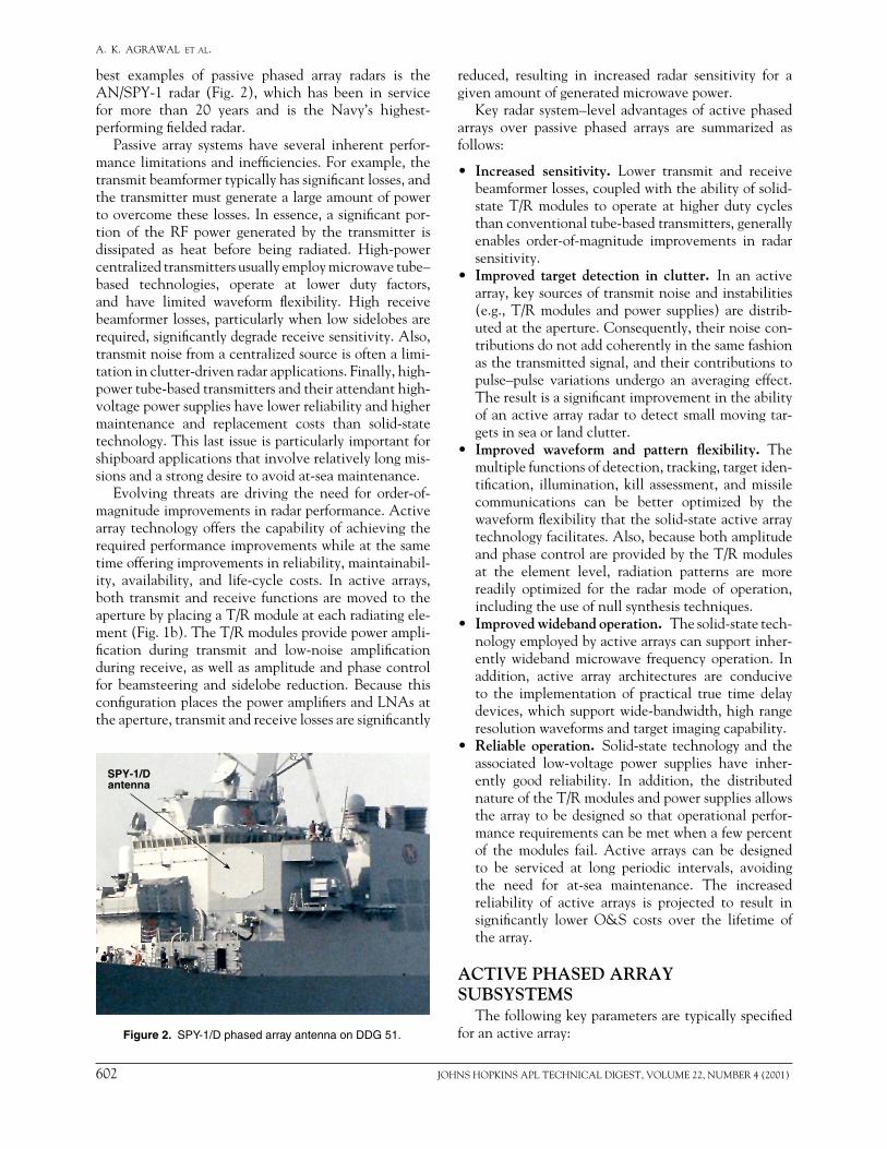
best examples of passive phased array radars is theAN/SPY-1 radar (Fig. 2), which has been in servicefor more than 20 years and is the Navy’s highest-performingfieldedradar.
Passive array systems have several inherent perfor-mancelimitationsandinefficiencies.Forexample,thetransmitbeamformertypicallyhassignificantlosses,andthetransmittermustgeneratealargeamountofpowertoovercometheselosses.Inessence,asignificantpor-tion of the RF power generated by the transmitter isdissipated as heat before being radiated. High-powercentralizedtransmittersusuallyemploymicrowavetube–based technologies, operate at lower duty factors,and have limited waveform flexibility. High receivebeamformerlosses,particularlywhenlowsidelobesarerequired,significantlydegradereceivesensitivity.Also,transmitnoisefromacentralizedsourceisoftenalimi-tationinclutter-drivenradarapplications.Finally,high-powertube-basedtransmittersandtheirattendanthigh-voltagepowersupplieshavelowerreliabilityandhighermaintenance and replacement costs than solid-statetechnology.Thislastissueisparticularlyimportantforshipboardapplicationsthatinvolverelativelylongmis-sionsandastrongdesiretoavoidat-seamaintenance.
Evolving threats are driving the need for order-of-magnitudeimprovementsinradarperformance.Activearraytechnologyoffersthecapabilityofachievingtherequiredperformanceimprovementswhileatthesametimeofferingimprovementsinreliability,maintainabil-ity, availability, and life-cycle costs. In active arrays,bothtransmitandreceive functionsaremovedto theaperturebyplacingaT/Rmoduleateachradiatingele-ment(Fig.1b).TheT/Rmodulesprovidepowerampli-fication during transmit and low-noise amplificationduringreceive,aswellasamplitudeandphasecontrolfor beamsteering and sidelobe reduction. Because thisconfigurationplacesthepoweramplifiersandLNAsattheaperture,transmitandreceivelossesaresignificantly
reduced, resulting in increased radar sensitivity for agivenamountofgeneratedmicrowavepower.
Keyradarsystem–leveladvantagesofactivephasedarrays over passive phased arrays are summarized asfollows:
• Increased sensitivity. Lower transmit and receivebeamformerlosses,coupledwiththeabilityofsolid-state T/R modules to operate at higher duty cyclesthanconventionaltube-basedtransmitters,generallyenables order-of-magnitude improvements in radarsensitivity.
• Improved target detection in clutter. Inanactivearray,keysourcesoftransmitnoiseandinstabilities(e.g., T/R modules and power supplies) are distrib-utedattheaperture.Consequently,theirnoisecon-tributionsdonotaddcoherentlyinthesamefashionasthetransmittedsignal,andtheircontributionstopulse–pulse variations undergo an averaging effect.Theresultisasignificantimprovementintheabilityofanactivearrayradartodetectsmallmovingtar-getsinseaorlandclutter.
• Improved waveform and pattern flexibility. Themultiplefunctionsofdetection,tracking,targetiden-tification, illumination, kill assessment, andmissilecommunications can be better optimized by thewaveformflexibilitythatthesolid-stateactivearraytechnologyfacilitates.Also,becausebothamplitudeandphasecontrolareprovidedbytheT/Rmodulesat the element level, radiation patterns are morereadily optimized for the radar mode of operation,includingtheuseofnullsynthesistechniques.
• Improved wideband operation. Thesolid-statetech-nologyemployedbyactivearrayscansupportinher-ently wideband microwave frequency operation. Inaddition, active array architectures are conduciveto the implementation of practical true time delaydevices,whichsupportwide-bandwidth,highrangeresolutionwaveformsandtargetimagingcapability.
• Reliable operation. Solid-state technologyandtheassociated low-voltage power supplies have inher-ently good reliability. In addition, the distributednatureoftheT/Rmodulesandpowersuppliesallowsthearraytobedesignedsothatoperationalperfor-mancerequirementscanbemetwhenafewpercentof the modules fail. Active arrays can be designedto be serviced at long periodic intervals, avoidingthe need for at-sea maintenance. The increasedreliability of active arrays is projected to result insignificantly lower O&S costs over the lifetime ofthearray.
ACTIVE PHASED ARRAY SUBSYSTEMS
Thefollowingkeyparametersaretypicallyspecifiedforanactivearray:
SPY-1/Dantenna
Figure 2. SPY-1/D phased array antenna on DDG 51.

JOHNSHOPKINSAPLTECHNICALDIGEST,VOLUME22,NUMBER4(2001) 603
ACTIVE PHASED ARRAY ANTENNA DEVELOPMENT
• Operatingfrequencyandbandwidth• Effectiveisotropicradiatedpower• Scancoverage• Beamwidths• Sidelobelevels(allmonopulsereceivechannels)• Trackingaccuracy• Waveformparameters(duty,pulsewidth)• Systemnoisefigure• Third-orderintercept• Stabilityandphasenoise• Harmonicandspuriousoutput• Reliability,maintainability,andavailability• Manufacturingandlife-cyclecosts• Primepowerrequirementsandcooling• Shipboardenvironmentalrequirements
Theoperatingfrequency,waveformparameters,andarrayperformancerequirementswillvarydependingonthe particular applications served by the radar. Theeffectiveisotropicradiatedpowerandbeamwidthdeter-mine the number of elements and the required T/Rmodule output power. The sidelobe levels determinethe amplitude and phase characteristics of the T/Rmodules,aperture,andtransmitandreceivebeamform-ers.Thephasenoise,stability,reliability,andmaintain-abilityrequirementsallinfluencethearrayarchitectureas well as the characteristics of the T/R modules andpower supplies. The antenna cost and weight dictatetheselectionoftechnologiesfordifferentcomponents
Radarcomputer
and displaySignal
processor
Exciter
∑receiver
∆ receiver
∆ receiver
∆ ∆receiver
T
∑
∆
∆
∆ ∆
Beamsteeringcontrol unit
AC-to-DC convertersand transformers
Ship power
Phased array antenna
Part of radar system
Beamformers
DC/DCdistribution
Logicdistribution
T/Rmodules
Controlelectronics
DC/DC
Antennastructure
Radiatingelements
Radome
Figure 3. Block diagram of an active phased array radar system.
and, in conjunction with the environmental require-ments, the array structure. The antenna cost, weight,andperformance typically forma critical design tradespace.
A block diagram of an active phased array radarsystemisshowninFig.3.Anactivephasedarraycon-sists of a transmit and receive antenna aperture thatincludestheradiatingelements,radome,andstructure;T/Rmodulesandassociatedcontrolcircuitry;RFbeam-formers; DC power distribution; and a beamsteeringcontroller.Keyfeaturesandfundamentaldesigntradesoftheseactivearraysubsystemsareaddressedinthefol-lowingparagraphs.
Transmit/Receive ModulesThe fundamental building block and key enabling
technology for active array radar antennas is the T/Rmodule. Depending on the application, active arrayscancontainhundredsor,moretypically, thousandsofT/R modules. These T/R modules have an importantroleindeterminingarrayperformance;theydrivemanyaspectsofthepackagingdesignandcanaccountforasmuchas50%of thecostof theactivearrayantenna.GaAsMMICtechnologyiskeytorealizingtherequiredmicrowavecircuitdensityinthesmallfootprintavail-able at each antenna element. Semiconductor batch-processingproductionofGaAsMMICsiskeytoachiev-ingtheactivearrayperformanceadvantagesatdesired

604 JOHNSHOPKINSAPLTECHNICALDIGEST,VOLUME22,NUMBER4(2001)
A. K. AGRAWAL et al.
arrayacquisitioncosts.AtypicalT/RmoduleisshowninFig.4.2
Figure 5 shows a block diagram of a typical T/Rmodule. Each module contains a transmit path and areceive path. The transmit path consists of a phaseshifter,avariablegainamplifierorattenuator(VGA),a driver amplifier, and a power amplifier. The poweramplifiersectionmayconsistofseveralpoweramplifiers,typicallytwoorfour,wheretheoutputpoweroftheseamplifiers is combined to obtain the required outputpowerfortheradiatingelement.Acirculatorisusedtoprovide theduplexing functionand isolationbetweentransmitandreceivepathsandtopreventloadpullingofthepoweramplifiercausedbyvariationsintheantennaelement’s input impedance changes during beamscan-ning.3Thereceivepathconsistsofalimiter,anLNA,aphase shifter,andavariableamplifierorattenuator.Thismodulearchitectureprovidesanoptimumperfor-mancecompromisewithrespecttomodulenoisefigure,third-orderintercept,anddynamicrange.4
Voltage regulation and digital control circuitry arealso often included in the T/R module. Local energystoragecanbeusedtomaintaintransmitpulsecurrentlevels and satisfy rise-time requirements. Also, seriesregulatorscanbeusedforsomeorallinternalvoltagesto reducepower supply rippleandnoise toacceptable
levelstomeetincreasinglyseverespectralpurityrequire-ments.5Low-resistanceHEXFETswitchesaretypicallyusedtocontrolthebiascurrentstothevariousampli-fiers. Digital signals to control the phase shifter andattenuatoraretypicallyfedseriallyintotheT/Rmoduletoreducepackagingcomplexity.Thisserialdatastreamis converted to parallel data with a shift register andclock signal. Memory may also be contained in themoduletoreducethetimerequiredtoswitchbetweenpredeterminedbeampositions.
T/Rmodulerequirementsarederivedfromthephasedarray antenna requirements andcanvary significantlydependingontheapplication.Thefollowingkeyparam-etersaretypicallyspecifiedforaT/Rmodule:
• Operatingfrequencyandbandwidth• Outputpower• Power-addedefficiency• Spuriousandharmonicoutput• Dutycycleandpulsecharacteristics• Receivenoisefigure• Receivegainandthird-orderintercept• Numberofamplitudeandphasebits• Amplitudeandphaseroot-mean-square(rms)errors• Meantimebetweenfailure(MTBF)• Cost
The frequency, bandwidth, and output power aredriven by the system application. A typical nominaloutput power for an X-band module, achievable withcommerciallyavailablepowerMMICs,isaround10W.Higher power levels are typical at lower frequencies.Power-added efficiency is an important parameter forminimizingtheprimepowerrequirementsandcoolingloadoftheactivearray.Dependingonthetechnologyused,transmit-power-addedefficienciesontheorderof20to25%aretypicallyachieved.LNAMMICnoisefig-uresinthemicrowaveregimetypicallyrangefrom1to2dB. Including lossesandothereffects,modulenoisefiguresinthe3-to4-dBrangearegenerallyachievable.Modules used in low sidelobe applications require ahighernumberofphasecontrolbits and lowerampli-tudeandphase rmserrors.Third-order intercept isanimportant parameter in mitigating interference fromsurface Navy radars where the radars, and thus themodules, are often operating in the vicinity of high-powerradarsonnearbyships.BecauseoftherelativelylongoperatingmissionsofsurfaceNavyradars,modulereliability is a critical factor in achieving low O&Scostsandminimalmaintenanceactions.AT/RmoduleshouldtypicallyhaveanMTBFinthehundredsofthou-sandsofhours.
Because of the large number of T/R modules inan active array, module production costs are criticalto active array affordability. Module production costscan vary depending on performance, design complex-ity,productionquantities,andotherfactors.Although
Limiter and LNA Phase shifter VGA
Power amplifiers Driver amplifier
Poweramp
Poweramp
Harmonicfilter
CirculatorPhaseshifter
VGA Amp
Amp
Driveramp
Switch
Switch
T/R
LNA Limiter
Figure 4. Photograph of a typical T/R module.
Figure 5. Block diagram of a typical T/R module.
JOHNSHOPKINSAPLTECHNICALDIGEST,VOLUME22,NUMBER4(2001) 605
ACTIVE PHASED ARRAY ANTENNA DEVELOPMENT
themodulecostbreakdowncanvarydependingontheapplication, the typical cost breakdown of an X-bandmodule(Table1) is representativeofcurrentstate-of-the-artX-bandT/Rmodules.ThecostofaT/Rmoduleconsists of the cost of the semiconductors (MMICs),packaging,othercomponents,assembly,andtest.TheMMICsaretypicallythemostsignificantcostelement.AmoredetailedT/Rmodulecostdiscussionisprovidedin Refs. 6 and 7. The MMIC cost will increase withhighermoduleoutputpower.
Semiconductorcostisdeterminedbywaferprocess-ing cost, wafer diameter, MMIC area, and yield. ThewaferprocessingcostforGaAsishighlydependentonthevolumeofwafersproducedbyafoundry.Foundriestypicallycanproducemorethan20,000wafersperyear.However,productionratesofatleast10,000wafersperyear are desirable to maintain low foundry overheadcosts.TypicalX-bandT/Rmoduleproductionratesdonot require a sufficient number of wafers to providehighfoundryloading.One4-in.waferhasenoughareato supply the GaAs needed for more than 50 typicalX-band modules. The production of 100,000 X-bandmodulesperyearwouldthusrequirelessthan20004-in.wafersperyearorlessthan10006-in.wafersperyear.Commercialvolumeusingsimilarpersonnelandfacili-tiesisrequiredtoprovidethelow-overheadstructureforcost-effectiveproductionofX-bandT/Rmodules.SomeGaAs producers have successfully achieved this prod-uctmixthroughhigh-volumesales tosupportwirelesshandsetproducts.
Radiating Elements and Antenna ApertureThecriticaldesigntaskfortheradiatingelementis
designingonethatradiatesefficiently,withgoodimped-ancematch,overtheoperatingfrequencybandandthescanvolumeof thearray.Cost is a significantconsid-eration because of the large number of radiating ele-ments typicallypresent.Because theperformanceofaradiating element is affected by mutual coupling withotherradiatingelements,theradiatingelementmustbedesigned for the radiatingenvironment rather thanasanisolatedelement.Thedesignprocessisusuallyiter-ative and consists of simulation using numerical elec-tromagneticmodelingtools,fabricationofawaveguidesimulatortoverifyperformanceataselectedscanangle,
andfabricationofasmalltestarray(generallyconsist-ingofupto100elements)toverifyfullperformance.Awell-designedelementwillprovideanelementpatternontheorderofcos1.25sovertheintendedscanvolume,wheresisthescananglefromarraybroadside.
Thelistofthedifferentkindsofelementsthathavebeenusedinarraysystemsincludesdipoles,microstrippatches, microstrip and waveguide slots, waveguides,horns,andflarednotches(Fig.6).8Thechoiceofele-ment depends on several factors, such as power han-dling, polarization, bandwidth, environmental condi-tions,feedingarrangement,andmanufacturingcost.
Dipolesandpatchesgenerallyhavenarrowbandwidth.The element bandwidth is defined in terms of loss ingainwithrespecttothecenterfrequency.Aflarednotchelement9 (Figs. 6a and 6b), where an open circuitedorthogonalcentralconductorexcitesthenotchesintheouter conductors, is typically used for wideband arrays.Bandwidths up to 6:1 have been demonstrated.10 For amicrostrip slot antenna, a cavity must be used behindeach slot to restrict radiation to the front hemisphere.AmicrostripslotradiatorisshowninFigs.6cand6d.
For high-power radar arrays, variants of the rect-angular or cylindrical waveguide radiating elements(Fig.6e)aregenerallyused.Waveguidearrays, thoughheavy,tendtohavelowlossandgracefulscandegrada-tion.Ridgedwaveguidescanbeusedforwide-bandwidthapplications.Single,double,andquad-ridgedwaveguidesare shown in Fig. 6e. Quad-ridged waveguides extendthese features to circularly polarized phased arrays.Often,thewaveguideelementisdielectricallyloadedtomatchitsimpedancetofreespace.Awide-angleimped-ancematching(WAIM)sheetcanbeusedtoproducesusceptancevariationwiththescananglethatpartiallycancelsthearrayscanmismatch.WAIMsheetsarelesspracticalforshipboardenvironmentsbecauseiceforma-tion at the aperture is not permitted, and some kindofheatingarrangementisrequired.Forexample,intheSPY-1antenna,iceisinhibitedbyplacingaluminawin-dowsontheindividualwaveguideradiatorsandheatingthesewindowsthroughconductionheating.
Microstrip patch elements (Fig. 6f) can be fab-ricated with low-cost lithographic techniques. Thetwo most common feed techniques are an in-linemicrostrip feed and a coaxial probe feed. Patch ele-ments are narrowband. For electromagnetically cou-pled patches in a phased array, the bandwidth canbe increased to more than 15% by choosing patchdimensions,substratethickness,anddielectricmateri-als.Usingdouble-stackedpatches,essentiallyprovid-ing a double-tuned element, can increase the band-widthfurther.
Radio-Frequency Beamformer ArchitecturesThe RF beamformer plays a critical role in deter-
miningtheradiationpatterns,particularlythesidelobe
Table 1. Typical T/R module cost breakdown.
PercentageofT/RCostelement modulecostMMICs 45%Package/substrates 25%Digital/analogcircuitry 15%Assembly 10%Test 5%

606 JOHNSHOPKINSAPLTECHNICALDIGEST,VOLUME22,NUMBER4(2001)
A. K. AGRAWAL et al.
levels, of an array radar. On transmit, the RF beam-former distributes the input signals to the individualT/Rmodules.Typically,this isdonesothateachT/Rmodule receivesan identical inputpower level.EqualamplificationineachT/Rmodulethenproducesauni-formtransmitaperturedistributionthatmaximizesthetransmitantennagain.
In the receive mode, amplitude tapering acrosstheapertureistypicallyappliedtoreducethereceive
sidelobe levels. Active array radars generally requirelowreceivesidelobestominimizesusceptibilitytojam-ming.Theamplitudeandphaseerror levels thatcanbemaintainedat theaperturedetermine theachiev-ablesidelobes.TheprimarysourcesoferrorincludetheT/RmodulesandtheRFbeamformers.Phaseshiftcon-trolintheT/Rmoduleprovidesamechanismforcali-bratingthemoduleandbeamformerphaseerrors.Toobtain low residual and quantization phase errors to
(a) Stripline-fed notch element
Striplineouter
conductor
Striplinefeed
(b) Notch element in an array
(c) Slot in a ground screen (d) Cavity-backed slot antenna
Slot Cavity
Baffle
Coaxialfeeder
(e) Waveguides
RectangularCircular
Ridge
(f) Electromagnetically coupled patch
Figure 6. Radiating elements for phased-array antennas.

JOHNSHOPKINSAPLTECHNICALDIGEST,VOLUME22,NUMBER4(2001) 607
ACTIVE PHASED ARRAY ANTENNA DEVELOPMENT
supportlowsidelobeperformance,asmanyas7bitsareusedinthedigitalphaseshifterMMICwithintheT/Rmodule.
Passivearrayradarshavesimilarrequirementsforlowsidelobes. The amplitude control can be applied onlyin thereceivebeamformers inpassivearrays,while theamplitudetapercanbeappliedeitherinthebeamformersorintheT/Rmodulesinactivearrays,asdescribednext.
To obtain sufficient tracking accuracy, radars typ-ically employ monopulse tracking techniques thatrequire separate receive channels, or RF beamformerarrangements, for the receive sum,deltaazimuth,deltaelevation,anddelta-deltachannels.Eachchannelhasanoptimumamplitudedistributionforlowsidelobeperfor-mance.Also,becausethechannelsareemployedsimulta-neously,asinglephaseshifterintheT/Rmodulecannotsimultaneously correct phase errors in all monopulsechannels,andoftensomecompromiseismadeinthedif-ference channel sidelobes relative to the sum channelsidelobes.Therearemanytrade-offsindevelopingbeam-formerarchitecturesforactivearrayradars.Twocommonexamplesarediscussedinthefollowingparagraphs.
Figure 1b shows a simplified beamformer architec-ture of a monopulse active phased array antenna. In
isdesiredif theradar istodetectsmallreturns.Thesetwoarchitectureshavebeenanalyzed,11andtheresultsshowthatforalargeactivephasedarrayantenna,thedifference in the noise figure for the two is approxi-mately0.5dB.Thechoiceofcommonorseparatebeam-formers is a function of beamformer complexity andantennanoisefigure.
DC Power DistributionBelow-deck AC-to-DC converters convert a ship’s
AC power into DC power that is supplied to thearrays.Thevoltageintoanactivearraytypicallyrangesfrom 200 to 500 VDC and, as such, is stepped downtovoltagelevelsrequiredbytheT/Rmodules(around10VDCorless)byDC-to-DCconverters.Therequire-ments for a DC-to-DC converter include voltage andcurrentrequirementsoftheT/Rmodules,outputvoltagedroopandripple,randomnoise,efficiency,dynamicstepresponse,andenoughinputandoutputenergystoragecapacitorsthatthemaximumdroopduetoloadchangeduringthelongesttransmitperiodmeetsrequirements.
DC power can be distributed in an array usingeither a distributed or a centralized system. In a dis-tributed system, a single DC-to-DC converter (power
Figure 7. Beamformer architecture with separate transmit and receive beamformers.
thereceivemode,theradiatingele-ments’ outputs are first combinedusing column beamformers. Theoutputs of the column beamform-ers are then combined using hor-izontal beamformers to form thesum,azimuthdelta,elevationdelta,anddelta-deltabeams.Thereceiveaperture weighting is applied inthe T/R modules by using theattenuatorsorvariable-gainampli-fiers. Because the receive ampli-tude weighting is applied in theT/Rmodules,thetransmitsumandreceivesumbeamformershaveuni-formdistributionandaresharedforthetransmitandreceivefunctions.Theorderofcolumnandrowcom-biningcanbeinterchanged.
Theamplitudetaperforanactivearray can also be applied in thebeamformers rather than in theT/R modules, as shown in Fig. 7.Becausetransmitandreceiveampli-tude tapers are different for thisarchitecture,separatebeamformersarerequiredforthesumreceiveandtransmitbeams.Althoughthearraywithseparatetransmitandreceivebeamformers is more complex, ithas a slightly lower receive noisefigure.Alowerantennanoisefigure
Sumtransmit
Sumreceive
Verticalcolumn
combiner
AZ delta
EL deltaDeltadelta
Horizontalcombiners
Verticalcolumn
combiner
T/Rmodule
T/Rmodule
T/Rmodule
Radiatingelement
Horizontalcombiner

608 JOHNSHOPKINSAPLTECHNICALDIGEST,VOLUME22,NUMBER4(2001)
A. K. AGRAWAL et al.
supply) feeds a small group of T/R modules (typicallytwotoeight)andDC-to-DCconvertersaredistributedthroughout the array, as shown in Fig. 8a. The DC-to-DC converters can be mounted on the same base-plateastheT/Rmodules.Inthecentralizedpowerdis-tribution system,agroupofDC-to-DCconvertersarecombinedtofeedalargesectionoftheantenna.Redun-dancy is provided in each group of power supplies toincreasereliability.ThecentralizedpowerdistributionisshowninFig.8b.
In both cases, the high-voltage DC is delivered totheconvertersusingalow-current,high-voltagebus.Inthecentralizedsystem,thelow-powerDCvoltagesaredistributedthroughoutthearray,requiringlow-voltage,high-currentbuses.Theconvertersconverthigh-volt-ageDCto lowvoltages requiredby theT/Rmodules,andvoltageregulationisprovidedtogeneratevoltageswith very small ripple. Both approaches provide forimprovedclutterperformancebecauseof theuncorre-latedrandomnoise.12However,theDC-to-DCconvert-ersforthecentralizedsystemcanbesignificantlylargerthanthoseofthedistributedsystemand,tocompensatefortheimpactofasmallernumberofDC-to-DCcon-verters on clutter performance, higher voltage regula-tionwouldberequired.
The DC-to-DC converters can be either averagepower or peak power switching frequency converters.Theswitchingfrequencydeterminesthesizeofthecon-verter, as the converter size decreases with increasingfrequency.Theaveragepowerconverters require stor-age capacitors to maintain the desired voltage droop.As the pulse width increases, the storage capacitancerequirementincreases,puttingaphysicallimitonthelengthofthepulse.TheotherapproachistouseapeakcapacitormultiplyingDC-to-DCconverter.Thiscon-verterhastheuniqueadvantagethatthepulseenergycanbestoredontheprimaryhigh-voltagesideoftheconverter,therebyresultinginasubstantiallysmaller
energystoragecapacitor.Bothconvertersarecompa-rable, and the choice of converter depends on pulsewidth,cost,andvolume.
Beamsteering ControllerTransmitandreceivebeamsinanactivephasedarray
antennaaresteeredbychangingthe insertionphaseofthe phase shifters contained in the T/R modules. Anantenna beamsteering controller (BSC) generates thephaseshiftcommandsforalloftheT/Rmodules.Gen-erationof thephase shiftcommandscaneitherbedis-tributedthroughoutthearrayorperformedinacentral-izedlocation.ThesetwoarchitecturesarereferredtoasadistributedBSCandacentralizedBSC,respectively.
In the distributed BSC architecture (Fig. 9a), acentral controller generates simple commands suchasscanangle, frequency, and timing.13TheT/Rmodulecontrolelectronicscontainanapplication-specificinte-gratedcircuit(ASIC),electricallyerasableprogramma-ble read-onlymemory(EEPROM),fieldeffect transis-tor(FET)switches,etc.ThephasesettingsforeachT/Rmodule are calculatedby theASIC, given the simpleinputcommandsandthemodule location.EEPROMsmay contain linearization amplitude and phase tablesfor eachT/Rmodule.Thesedata aremodule specific,storedinEEPROMsonthebasisofmodulefactorytestresults,andcanbeerasedandreloadedwithnewdataatanytime.ThedatatransferratefromASICtoT/Rmodulescanbeoftheorderof20Mbps.
Inadditiontosendingthescanangleandfrequency,the central controller sends a command to set theantenna ineither transmitor receivemodeby settingswitchesappropriatelyintheT/Rmodules.Alocalcrys-tal oscillator generates the clock at each local groupof modules. The clock speed determines the time ittakesforcommandstoreachallT/Rmodules.Distrib-utingtheclockatthelocallevelminimizesthenoise,becausetheclocksarenotsynchronized.Becausemany
Figure 8. (a) Distributed and (b) centralized power distribution architecture.
(a)
High-voltageDC bus
High-voltageDC bus
DC-to-DCconverter
AC-to-DCconverters
Shippower
Low-voltage DC bus Low-voltage DC bus
High-voltage DC busHigh-voltage DC bus
DC-to-DCconverter
AC-to-DCconverters
(b)

JOHNSHOPKINSAPLTECHNICALDIGEST,VOLUME22,NUMBER4(2001) 609
ACTIVE PHASED ARRAY ANTENNA DEVELOPMENT
Figure 9. (a) Distributed and (b) centralized beamsteering controller architecture.
differentbeam-direction/gain-phasecombinationscanbestoredinmemoryinadvance,switchingcanreadilybeaccomplishedamongvariousbeamswithout recal-culationwithinasingledwell.
In the centralized BSC architecture (Fig. 9b), mostofthecomputationsareperformedinacentrallocationand the data required by each T/R module are sentdirectly to theT/RmodulesorgroupsofT/Rmodules,suchas lowest replaceableunits (LRUs),usingparallelbuses.Thecentralbeamsteeringcontrollermaycontaina number of digital signal processor (DSP) cards; eachcardisassignedresponsibilityforaspecificgroupofT/Rmodules and stores all calibration values (linearizationtables)forthatgroupofmodules.EachDSPcardperformsasetofbeamsteeringcalculationsforeachT/Rmoduleinitsgroupwithinaminimumpulserepetitioninterval(PRI).ThePRIandthenumberofmodulesdeterminethetotalcomputationrequirement.Severalparallelprocessorsmaybeneededtomeettherequirements.Thedatathatcontain thephaseandgainbitsandthatare sentoverthecontrollinesmustbemanipulatedforfinaldeliverytotheT/Rmodule.ForthecentralizedBSCarchitecture,thisfunctioncanbeimplementedinfield-programmablegatearraysthatcaneasilybereprogrammedtomeettherequirementsofanewT/Rmodule.
TheadvantagesofthecentralizedBSCincludecen-tralprocessorsthatcanbepurchasedcommerciallyandreconfiguredfordifferentradarsystems.Thecentralcon-trollocationrequiresasubstantialdataflowbetweenthecentral control unit and the T/R modules. For a largeactive phased array, the data rates can range between100and500Mbps,requiringsimilarclockspeeds.Fiber-opticdatalinksmaybeappropriateatthesespeeds.
EitherthedistributedorthecentralizedBSCarchi-tecturecanbeadopted fora largeactivephasedarraysystem. Preliminary estimates show that the cost ofthesetwoarchitecturesisverysimilar.
Mechanical PackagingThe predominant packaging considerations associ-
atedwiththemechanicaldesignofactivephasedarray
antennasincludedesignforeaseofmaintenance,ther-mal management, packaging the DC power distribu-tionsystem,RFbeamformers,radiatingaperturedesign/interface, and structural design.Theoverridingdriverinwhatpackagingoptionsareavailabletothedesigneris the antenna operating frequency. As the frequencyincreases, element spacing decreases, requiring tighterspacingofthesupportingelectronics.Fortunatelyforthedesigner,higher-densityarraystendtohavelowerT/Rmoduleoutputpower requirements;hence, theworst-casethermaldesignproblemstypicallydonotcorrelatewiththeworst-casepackagingdensities.
Tooptimizeanarraydesignforeaseofmaintenance,mostoftheactiveelectronicsareconfiguredasLRUs,which can include T/R modules, DC-to-DC powerconverters, and various control/processor assemblies(Fig.10).ReliabilityandsystemimpactintheeventoffailuredeterminewhetheranassemblyisdesignedasanLRU. System architecture, LRU reliability, and LRUcostdefinewhatisincludedwithinagivenLRU.Faultisolation down to at least the LRU level is providedtominimizeservicetimerequiredduringmaintenanceactions. Structural components, the coolant distribu-tion system, RF beamformers, DC power distribution,and cabling are typically considered of sufficient reli-abilitytobenonrepairableatsea.
Thermaldesign is critical formaintaining junctiontemperaturesoftheelectronicsatdesiredlevelstosup-port reliability requirements and maintain control oftemperature-induced module-to-module phase errors.TheT/Rmodulesaccountfor70–80%oftheheatgen-eratedwithinanarray.Becauseofever-increasingpowerdensity heat dissipation in modern shipboard activephasedarrays,liquidcoolingisnormallyrequired.Thepredominant cooling techniques in use today employconductionawayfromtheT/Rmoduleintoliquid-filledcoldplatesordirectliquidflow-throughcoolingonindi-vidualLRUs.Ifthespacingallowselectronicstobecon-tainedononesideoftheLRU,theLRUscanbedirectlyattachedtothecoldplatesconductingacross the largesurface area opposite the components. Alternatively,
RCCBSC
centralcontroller
ASIC/controlmodule
(a)
Channel driver cardsRCCBSC
centralcontroller
DSP cards
Column controllers(each controls
1–16 T/R modules)
(b)
Ch n

610 JOHNSHOPKINSAPLTECHNICALDIGEST,VOLUME22,NUMBER4(2001)
A. K. AGRAWAL et al.
LRUs can be edge cooled. Figure 10 shows a typicaledge-cooledLRU.Ascomponentpowerdensitiescon-tinuetoincrease,itmaybecomenecessarytomounttheT/Rmodulesdirectlytoliquid-filledcoldplates.
Because T/R modules exhibit phase changes withtemperature variations, tight thermal control of themodulesmustbemaintainedacrossanarray.PhaseerrorscanbeactivelycompensatedforiftheMMICtempera-tureisknown.However,becauseofthedifficultyinmea-suringtheactualgatetemperaturesduringvariousopera-tionalmodesanddutycycles,thishasnotbeenshowntobepractical.Currenttechniquesfocusonmaintaininguniformcoolanttemperaturesacrossthearrayandcal-ibrating each element during one or more operatingmodes.
Maintenancerequirementsusuallydictatethatcom-ponents not require removal to replace an LRU. Inaddition, maintenance must be performed from thebackside(deckhouseinterior)ofthearray,andthere-fore LRUs are inserted and extracted from the backof the array. It is imperative that RF beamformers,powerdistributionsystems,controlsignaldistributionsystems, and their associated cabling be installed inamanner that allows ready access to theLRUs, andtheseelementsmustbedesignedtofitbetweentheT/RmoduleLRUs.ThisrequiresblindmateconnectionstotheLRUsfromthecontrol,power,andRFdistribution(andtoliquidconnectionsonliquid-cooledLRUs).
Two packaging configurations are shown in Fig.11. In Fig. 11a, the T/R modules are mounted on athermallyconductivebaseplateattachedtotheliquid-cooledmountingstructure.Thisdesignissimilartothetechniqueemployedinairtransportablerackequipmentandallowscomponentstobemountedtobothsidesofthebaseplate.This techniqueoffers a simple, easy-to-maintainpackagingdesignthatcanaccommodatetightelement spacing. In addition, the coldplates becomepartoftheantennastructure.Becauseoftheincreasedthermalpath length, thepowerdissipationcapacity issomewhatpowerlimited.
T/Rmodule
DC-to-DCconverter
Controlcircuits Baseplate
Top view Side view
Figure 10. T/R module LRUs: components on both sides of a baseplate.
In the configuration shown inFig. 11b, the T/R modules aremounted to one side of an LRUbaseplate. The single-sided LRUsare mounted on a large vertical,fixed coldplate using wedge locksto press the baseplate against thecoldplate. This configuration pro-vides a large contact area to thecoldplate and allows easy accesstotheLRUs;however,ittendstobe better suited to larger elementspacing,whichallowsLRUattach-mentbyinsertionononeside.Theprimarydifficultyinthisapproachcomes from theLRU-to-coldplate
interface. To readily accommodate sliding insertionand extraction, the interface needs to be free offillermaterial.Thisrequirestighttolerancecontrolofbothsurfacesandmakesachievingrepeatablethermalresistance from module to module difficult. Alterna-tively, a phase-change–type interface material couldbeemployedthatwouldrequireheatingtheinterfacepriortoextraction.
(a)
(b)
Figure 11. Antenna packaging assembly with (a) horizontal man-ifolds (edge-cooled LRUs) and (b) fixed vertical coldplates (one-sided LRUs mounted directly on both sides of the coldplates).

JOHNSHOPKINSAPLTECHNICALDIGEST,VOLUME22,NUMBER4(2001) 611
ACTIVE PHASED ARRAY ANTENNA DEVELOPMENT
LRUs either must contain the radiating elementsormustblindmate to the radiatingelementson thearray face. For low-sidelobe radar arrays, the latteris typically the case when the radiating elementsare machined out of a faceplate to maintain tightelement location tolerances. Overall mechanicalalignment between the LRU and the radiating ele-mentrequirestightcontroloflarge-tolerancestackups,and the resulting misalignment must be absorbed intheRFconnector.Therecaneasilybe15 to25 tol-erances,whichcombinetodeterminetheradialfloatrequired in theRF connector.Becausemost floatingRFconnectorsoffernomorethan0.030in.ofradialfloat, it is necessary to use a combination of tighttolerances,statisticaltolerancingmethods,andocca-sionallyspecializedassemblyfixturestoensureproperalignment.
Structuraldesignisasignificantissueforshipboardactive array radars. Traditionally the shipboard shockrequirement(Mil-Std-901)hasbeenthepredominantstructuraldesigndriver.Formostantennasystems,float-ingplatformbargetestingisrequired.Thesetestsimparta shock pulse on the order of 70 g at 11–14 Hz. Asecondary consideration is tomaintain adequate stiff-nessintheradiatingaperturetoensurethatarrayflat-nessrequirementsaremaintainedduringoperationalseastatesandshipboardstructuralvibrations.Thisflexuralstiffness directly contributes to the array error budgetandmustbeaccountedfor.Maintainingadequateflat-ness, particularly in larger,high-frequency arrays,willbecome increasingly difficult. One technique beingexplored isactivemeasurementandcompensation fordeflection.Inaddition,errorbudgetsmustaccountforlarge-scaledeflectionsoftheship’sstructuralmovementsuchasdeckhouseormastdeflections.
RELIABILITY AND LIFE-CYCLE COSTAchievinglife-cyclecostrequirementsiscriticalto
theacquisitionofanynewactivearrayradarsystemfortheU.S.Navy.Life-cyclecostconsistsofdevelopment,acquisition, installation, O&S, and disposal costs, ofwhichtheacquisitionandO&Scostsarethemaincon-tributors.Thekeystoreducinglife-cyclecostsaremin-imizing the cost of spares and, through fault-tolerantdesignoftheantennaarchitecture,minimizingthefre-quencyofmaintenanceactions.
The reliability of the antenna is measured in twoways: MTBF and mean time between critical failures(MTBCF).TheMTBFofalargephasedarrayisquitelow because of the large number of components. Itthereforebecomescriticaltoincorporatefaulttoleranceintothedesign.14,15Becauseof theredundancyoftheelectronics supporting each radiating element, activephased array antennas are inherently fault tolerantand can be readily designed to degrade gracefully.
ConsequentlytheyareprojectedtoachieveanMTBCFsufficient to support ship deployment periods with noscheduledmaintenance.
ThekeytoreducingO&ScostisthereliabilityandredundancyoftheindividualLRUs.TheLRUsmustbeoptimallysizedtominimizecost,partscount,andper-formanceimpact intheeventof failure,yetbeofsuf-ficientsizeforarraypackagingandmaintenanceaccessconsiderations.AntennaacquisitioncostsareprimarilydrivenbytheT/Rmodule;however,LRUassemblyandDC-to-DCconvertercostscanalsobesignificant.Keytoreducingthesecostsisattentiontoproduceabilityandeliminationoftouchlaborintheassembly.Becauseofthehighlyredundantnatureofthearchitecture,manyLRUs are produced in sufficient quantities to warranttruedesignforproduction.
Becauseofthecombinationofaninherentlyredun-dant architecture and highly reliable solid-state elec-tronics (notably T/R modules), active arrays are pro-jectedtoprovideimprovedreliabilityandreducedO&Scostsrelativetoconventionalarrayradarsystems.
CONCLUSIONActivearrayantennashaveemergedasafundamen-
tal technology for addressing evolving surface Navyradarsystemneeds.Newshipboardactivearrayradarscurrentlyunderdevelopment includetheAN/SPY-3multifunction radar, volume search radar for long-rangesurveillance,anddevelopmentalradarconceptsfor Navy Theater Wide Ballistic Missile Defense.Largely as a result of active array technology, thesenewradarsareprojected toprovidedramaticperfor-mance improvements as well as improved reliabilityandreducedO&Scostsrelativetoconventionalradarsystems.
Thisarticlepresentedanoverviewofthekeyaspectsofanactivearrayanditsvarioussubsystems.Thecur-rent state of the art was described, with particularemphasisonthecriticalT/Rmoduletechnology.T/Rmodulecostconsiderationswerealsoaddressed,giventhe significant focus on achieving affordable radaracquisitioncosts.
REFERENCES 1Frank,J.,andO’Haver,K.,“PhasedArrayAntennaDevelopmentat
theAppliedPhysicsLaboratory,”Johns Hopkins APL Tech. Dig.14(4),339–347(1993).
2Komiak, J., and Agrawal, A., “Design and Performance of OctaveS/C-Band MMIC T/R Modules for Multifunction Phased Arrays,”IEEE Trans. Microwave Theory Tech. 39(12), 1955–1963 (Dec1991).
3Jones, R., and Kopp, B., “Duplexer Considerations for X-Band T/RModules,”Microwave J.43,348–352(May2000).
4Agrawal, A., Clark, R., and Komiak, J., “T/R Module ArchitectureTrade-offs for Active Phased Array Antennas,” 1996 IEEE MTT-S Int. Microwave Symp., San Francisco, CA, pp. 995–998 (17–21 Jun1996).
612 JOHNSHOPKINSAPLTECHNICALDIGEST,VOLUME22,NUMBER4(2001)
A. K. AGRAWAL et al.
5Moore,C.,andKopp,B.,“PhaseandAmplitudeNoiseDuetoAnalogControlComponents,”Microwave J.41,64–72(Dec1998).
6Kopp,B.,“X-BandTransmit/ReceiveModuleOverview,”IEEE MTT-Symp.,Boston,MA,pp.705–708(Jun2000).
7Cordner, T., “GaAs Cost Drivers and an Approach to AchievingLow Cost Products,” Int. Conf. of GaAs Manufacturing Technol.,pp.153–159(1997).
8Mailloux, R. J., Phased Array Antenna Handbook, Artech House(1994).
9Lewis,L.R.,Fasset,M.,andHunt,J.,“ABroadbandStriplineArrayElement,” IEEE AP-S Symp. Dig., Atlanta, GA, pp. 335–337 (Jun1974).
10Monser,G.J.,“PerformanceCharacteristicsofNotchArrayElementsOver6:1FrequencyBand,”1987 Antenna Application Symp.,Univer-sityofIllinois(1987).
THE AUTHORS
ASHOKK.AGRAWALreceivedaPh.D.inelectricalengineeringin1979fromtheUniversityofNewMexico.HeworkedasaresearchscientistatMissionResearchCorporationinAlbuquerque,NewMexico,from1976to1982andasaPrincipalEngineeratLockheedMartinCorporationinMoorestown,NewJersey(previouslyRCA,GE,andMartinMarietta),from1983to1999.AtLockheedDr.Agrawalwasinvolvedinresearchanddevelopmentprogramsonvariousphasedarrayantennasandalsoledthedevelopmentofseveralactivephasedarrayantennaprograms.In1999hejoinedAPLandiscontinuingresearchanddevelopmentworkonactivephased array antennas. Dr. Agrawal has published numerous papers in IEEE andother journals andholdsfivepatentsonphased array antenna topics.His [email protected].
11Agrawal,A.,andHolzman,E.,“BeamformerArchitecturesforActivePhasedArrayRadarAntennas,”IEEE Trans. Antennas Propag.AP-47,432–442(Mar1999).
12Holzman,E.,andAgrawal,A.,“ActivePhasedArrayDesignforHighClutterImprovementFactor,”IEEE Int. Symp. Phased Array Technol.,Boston,MA,pp.44–47(15–18Oct1996).
13Deluca, A., Gentry, J., Thomas, D., Landry, N., and Agrawal, A.,“PhasedArrayAntennawithDistributedBeamsteering,”U.S.PatentNo.5339086(16Aug1994).
14Agrawal,A.,andHolzman,E.,“ActivePhasedArrayArchitecturesforHighReliability,”IEEE Int. Symp. on Phased Array Technol.,Boston,MA,pp.159–162(15–18Oct1996).
15Agrawal,A.,andHolzman,E.,“ActivePhasedArrayDesignforHighReliability,”IEEE Trans. Aerosp. Electronic Sys.35,1204–1210(Oct1999).
BRUCEA.KOPPreceivedaB.S.E.E.fromArizonaStateUniversityin1986andan M.S.E.E. from Stanford University in 1988. He was employed at Avantek inMilpitas,California,asamicrowaveandRFcomponentandsubsystemdesignengi-neerfrom1986to1990,workingonpassiveandcontrolcircuitdevelopmentusingprintedlumpedelements.Mr.KoppisamemberofthePrincipalProfessionalStaffat APL where he has been employed since 1990 developing T/R modules andassociatedpackagingandsolid-statetechnologiesforphasedarrayradarandcom-munications systemsapplications.Mr.Kopphasparticipated in thedevelopmentof 30 different T/R modules and has been the author or co-author of 17 papersrelated toT/Rmodulesand related technologies. Inaddition,he teachesa3-dayshortcourseonT/Rmodulecost,performance,[email protected].
MARK H. LUESSE, a member of the APL Senior Professional Staff in the AirDefenseSystemsDepartment,receivedaB.S.inmechanicalengineeringfromtheUniversity ofMaryland.Before joiningAPL in1989,heworked atAAICorpo-rationinHuntValley,Maryland,asadesignengineerdevelopingsimulationandtestequipment.AtAPL,hehasdesigned,analyzed,andmanagedvarioushardwaredevelopmentandfield test siteefforts.Mr.Luesse joinedADSD’sRadarSystemsDevelopment Group in 1996, working primarily on the mechanical design andpackagingoversightofactivephasedarrayradarandcommunicationsantennas.Hise-mailaddressismark.luesse@jhuapl.edu.

JOHNSHOPKINSAPLTECHNICALDIGEST,VOLUME22,NUMBER4(2001) 613
ACTIVE PHASED ARRAY ANTENNA DEVELOPMENT
KENNETHW.O’HAVERisamemberofAPL’sPrincipalProfessionalStaffandisSupervisoroftheAirDefenseSystemsDepartment’sRadarDevelopmentGroup.HereceivedaB.S.inelectricalengineeringfromVirginiaTechin1981andanM.S.inelectricalengineeringfromTheJohnsHopkinsUniversityin1984.Mr.O’HaverjoinedAPLin1984andhasbeenengagedinthedevelopmentofphasedarrayandactiveapertureantennasystemsandtechnologies forshipboardradarapplicationsandshipboardandairbornecommunicationsapplications.HeistheleadengineeratAPLforantennadevelopmentfortheNavy’sCooperativeEngagementCapabilityProgramandistheNavyIntegratedProductTeamleadforSPY-3radararrayantennaequipmentdevelopment.Hise-mailaddressiskenneth.ohaver@jhuapl.edu.
Recommended