Form
#46
0 R
ev B
Phon
e: 2
69-7
89-6
700
Fax:
269
-781
-834
0 E-
mai
l: sa
les@
mar
shal
lexc
elsi
or.c
om
ww
w.m
arsh
alle
xcel
sior
.com
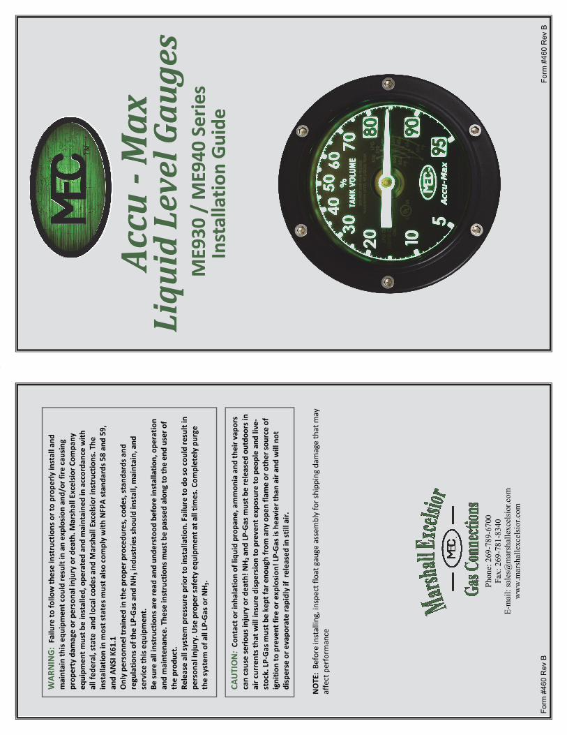
CAUTION: Co
ntact o
r inh
alation of liqu
id propa
ne, ammon
ia and
their v
apors
can cause serio
us injury or d
eath! N
H3 a
nd LP‐Gas m
ust b
e released
outdo
ors in
air currents that will insure dispe
rsion to prevent exposure to peo
ple an
d live‐
stock. LP‐Gas m
ust b
e kept fa
r eno
ugh from
any
ope
n fla
me or other sou
rce of
ignitio
n to prevent fire or e
xplosion
! LP‐Gas is heavier th
an air an
d will not
disperse or e
vapo
rate ra
pidly if re
leased
in still air.
NOTE: Be
fore installing, inspect float gauge assem
bly for shipp
ing damage that m
ay
affect perform
ance
WAR
NING: Failu
re to
follo
w th
ese instructions or to prop
erly install and
maintain this equ
ipmen
t cou
ld re
sult in an explosion an
d/or fire cau
sing
prop
erty dam
age or persona
l injury or death. M
arshall Excelsior Com
pany
eq
uipm
ent m
ust b
e installed, ope
rated an
d maintaine
d in accorda
nce with
all fed
eral, state and
local cod
es and
Marshall Excelsior instructions. The
installatio
n in m
ost states m
ust a
lso comply with
NFPA stan
dards 5
8 an
d 59,
and AN
SI K61.1
Only pe
rson
nel trained
in th
e prop
er procedu
res, cod
es, stand
ards and
regulatio
ns of the
LP‐Gas and
NH3 ind
ustries s
hould install, maintain, and
service this equ
ipmen
t. Be
sure all instructio
ns are re
ad and
und
erstoo
d be
fore installatio
n, ope
ratio
n an
d mainten
ance. The
se instructions m
ust b
e pa
ssed
along
to th
e en
d user of
the prod
uct.
Release all system pressure prior to installatio
n. Failure to
do so cou
ld re
sult in
person
al injury. U
se prope
r safety eq
uipm
ent a
t all tim
es. C
ompletely pu
rge
the system
of a
ll LP‐Gas or N
H3.
Form
#46
0 R
ev B
Accu
Accu
Accu‐ ‐‐ Max
Max
Max
LiquidLevelGauges
LiquidLevelGauges
LiquidLevelGauges
ME930
/ M
E940
Series
ME930
/ M
E940
Series
ME930
/ M
E940
Series
Installatio
n Guide
Installatio
n Guide
Installatio
n Guide

CA
UTION
Read
com
pletely be
fore attem
pting installatio
n. The
se instructions are prepa
red
to assist q
ualified individu
als a
nd others gene
rally fa
miliar with
liqu
id storage
tank
equ
ipmen
t. M
ost con
sumers are no
t qua
lified to perform
the installatio
n
describ
ed. If you ha
ve any
que
stions abo
ut installatio
n or ope
ratio
n of Accu‐Max
float gau
ges, con
tact th
e Marshall Excelsior Co., o
r an au
thorized
distributor fo
r assistan
ce.
*Spe
cifications are sub
ject to
cha
nge with
out n
otice. Pressure ratin
gs sub
ject to
cha
nge
due
to te
mpe
rature and
other env
ironm
ental con
side
ratio
ns.
Constructio
n & Ope
ratio
n Accu‐M
ax liqu
id level gauges a
re designe
d for cen
terline
mou
nting on
bulk‐storage
tanks a
nd bob
tails or transpo
rts.
The materials used
in con
struction are carefully se
lected
for com
patib
ility with
the
liquid to be gauged
, so, you
can
expect the
unit to provide many years o
f troub
le‐free
service.
Accu‐M
ax gauges a
re ope
rated by liqu
id disp
lacemen
t of a
float b
ulb attached
to a
coun
ter‐balanced
float a
rm. The coun
terbalance has been adjusted
so th
at th
e flo
at
will be half‐subm
erged in th
e tank’s liqu
id.
The main gear at the
pivot point driv
es a pinion gear attache
d to a cen
ter shaft. The
2.2:1 gear ra
tio con
verts the
140
° float arc to
308
° of cen
ter shaft ro
tatio
n. A
driv
e magne
t, attached
to th
e en
d of th
e center sh
aft u
nder th
e gauge he
ad, cou
ples with
a
dial pointer m
agne
t throu
gh th
e solid, non
‐magne
tic head to m
ove a po
inter a
roun
d a
dial, gradu
ated
in percent of tank volume. The
limits of m
easuremen
t are 5% ‐ 95%
for b
obtails or transpo
rts a
nd 3% ‐ 97% of tank volume for b
ulk‐storage tanks.
Centerlin
e Mou
nt
Attachmen
t To Tank
Diffe
rent adapters c
an be welde
d or sc
rewed
into ta
nks to attach th
e gauge.
The mou
nting bo
lt ho
les for all Accu‐M
ax float g
auges a
re on the vertical cen
terline
.
The Accu‐M
ax float g
auge m
ust b
e mou
nted
to one
of the
following MEC
adapters,
P/N M
E931, which has a 2.5” Male NPT
thread
which sc
rews into a 2.5” Fem
ale NPT
coup
ling welde
d into th
e tank
or P
/N M
E932, w
hich is designe
d to be welde
d directly
to th
e tank. The sealing gasket, fou
r seal locators and eight m
ounting stud
s and
nuts
are includ
ed with
the Accu‐M
ax float g
auge.
1
Accu M
ax Lim
ited Warranty
Marshall Excelsio
r warrants A
ccu‐Max float g
auges a
nd re
pair kits to
the original buyer
to be free
of d
efects in
material and
workm
anship und
er normal se
rvice and use for
two years from th
e manufactured date. If a bu
yer p
erceives a produ
ct to
have a de
‐fect, the
buyer m
ust n
otify
Marshall Excelsio
r’s hom
e office in writing with
in 20 days of
know
n pe
rceived de
fect and
the prod
uct m
ust b
e po
st‐m
arked and shippe
d F.O.B.
origin with
in 30 days to
Marshall Excelsio
r’s hom
e office after k
nown pe
rceived de
fect.
Marshall Excelsio
r will not accep
t any
produ
ct th
at doe
s not have a Re
turn M
aterial
Authoriza
tion (RMA) num
ber from th
e ho
me office in M
arshall, MI. After M
arshall
Excelsior has inspected the prod
uct a
nd deems the
produ
ct to
be de
fective, at its
discretio
n, M
arshall Excelsio
r will re
pair, re
place or re
fund
the pu
rchase price of th
e de
fective prod
uct. If th
e bu
yer d
oes n
ot com
ply with
the above stated
, the
buyer will
waive uncon
ditio
nally and
absolutely any and all claim
s arising ou
t of such pe
rceived
defect.
10
Part #
Descriptio
n ME930
‐239
Glass fo
r 4"dial
ME930
‐240
Glass se
al fo
r 4" dial
ME940
‐210
Glass fo
r 8"dial
ME940
‐211
Glass se
al fo
r 8" dial
ME930
‐212
Mou
nting fla
nge gasket ‐ Spira
l wou
nd stainless steel, PTFE ‐ filled
ME930
‐255
Plastic
seal locators, .75''O
D x .49''ID
‐ Po
ly
ME930
‐244
Stainless s
teel dial screw
‐ #10‐32
UNF‐2A
ME930
‐243
Stainless s
teel Dial nut ‐ #10‐32
UNF‐2B
ME930
‐223
He
x nu
t, 1/2"‐13 UNC‐2B
ME930
‐224
Stud
bolt, 1/2"‐13 UNC‐2A
ME930
‐222
4" Dial m
ounting bracket
ME940
‐206
8" Dial m
ounting bracket
ME930
‐905
4" Dial, LPG & NH3
, 5% ‐ 95%
ME940
‐905
8" Dial, LPG & NH3
, 3% ‐ 97%
ME930
‐211
Float b
ulb ‐ 2
" dia. x 4 1/4" long
ME930
‐903
‐72
Float b
ulb and Arm assem
bly for 7
2 dia. DOT tank
ME930
‐903
‐79
Float b
ulb and Arm assem
bly for 7
9 dia. DOT tank
ME930
‐903
‐84
Float b
ulb and Arm assem
bly for 8
4 dia. DOT tank
ME940
‐903
‐108
Float b
ulb and Arm assem
bly for 1
08 dia. A
SME stationary ta
nk
ME940
‐903
‐130
Float b
ulb and Arm assem
bly for 1
30 dia. A
SME stationary ta
nk

9
Trou
ble Shoo
ting
SY
MPTOM
LO
OK FO
R:
Gau
ge not re
ading at lo
w
extrem
e whe
n installed in
empty tank
.
Float striking ob
struction such as d
ip pipes
or b
affle
s.
Float o
r cou
nterbalance strik
ing tank
wall.
‐ Incorrect gau
ge.
Float n
ot dropp
ing un
der its own weight.
‐ Defective ga
uge.
Float a
rm to
o short for cou
nterbalance.
Gau
ge con
tinue
s reading
at
low extreme whe
n tank
is
full.
Obstructio
n on
tank
bottom.
Float improp
erly cou
nterbalanced
for liquid
being gauged
. ‐ O
rder correct gau
ge.
Float leaks and
is filled with
liqu
id.
‐ Replace floa
t.
Gau
ge indicator staying
at
some midpo
int regardless o
f liq
uid level.
Float h
ung no
t allowing flo
at to
follow liqu
id
level. ‐ D
efective ga
uge.
Float p
artia
lly su
nk due
to leakage or im
prop
er
coun
terbalancing.
‐ Replace floa
t or g
auge.
Dial pointer is stuck du
e to dam
age or corrosio
n.‐ R
eplace dial.
Incorrect o
r mod
ified
float a
rm installed or
gauge. ‐ Re
place flo
at arm
or g
auge.
Gau
ge indicatin
g liq
uid level
inaccurately.
Gauge not fitting tank. ‐ O
rder righ
t gau
ge
Gauge m
ounting adapter n
ot aligne
d with
tank
axis.
Tank
is not level.
Liqu
id‐tem
perature volum
e changes n
ot
accoun
ted for.
Gau
ge fa
ce not straight on
tank
. Mou
nting adapter lined
up im
prop
erly.
Ce
nterline gauge used
on stradd
le m
ount
adapter.
2
The minim
um adapter ope
ning
diameter th
e flo
at and
cou
nterbalance must p
ass
through is 2.25
”. A
ny adapter used must b
e installed with
its a
xis truly aligne
d with
the tank
axis. This e
nables th
e installed gauge to be exactly
horizo
ntal and
provide
accurate gauge re
adings.
Inspectio
n & Assem
bly of Gau
ge
Whe
n the Accu‐M
ax float g
auge is re
ceived
, rem
ove and inspect it to make sure it is
in ope
ratin
g cond
ition
. Use th
e screws a
nd nuts p
rovide
d to install the
float a
rm and
dial onto the gauge. M
ake sure th
e flo
at will fa
ll un
der its own weight b
y moving the
float arm
slow
ly th
rough its ra
nge to detect a
ny binding
or restrictio
n. The
dial
pointer sho
uld move slightly
past the
extreme en
ds of the
dial scale whe
n the flo
at
arm re
ache
s the
limits of its travel.
Make sure it is calibrated prop
erly by aligning
the flo
at arm
with
the supp
ort a
rm.
The gauge shou
ld th
en re
ad 50%
. The 50% gradu
ation on
the dial sh
ould be at th
e 12
o’clock po
sition after the
gauge is installed in th
e adapter. If you
find
any
problem
s call Marshall Excelsio
r Co.
Accuracy Precaution
Before installing your Accu‐Max gauge, be sure it fits you
r tank prop
erly. Ch
eck the
length of the
float a
rm, m
easurin
g from
the pivot p
oint to
the center of the
float b
ulb.
This dimen
sion shou
ld be approxim
ately .465
times th
e insid
e diam
eter of a
ny
horizon
tal cylindrical ta
nk, and
.428
times th
e insid
e diam
eter fo
r mob
ile ta
nks.
Before filling
the tank, be sure th
e gauge moves freely insid
e. M
any storage tanks
contain dip pipe
s, baffle
s, or o
ther obstructio
ns which m
ay interfere with
free
movem
ent o
f the
gauge float a
rm, preventing prop
er perform
ance.
Accurate m
easuremen
t of Lique
fied‐Pe
troleu
m Gas (LP Gas) o
r anh
ydrous ammon
ia
(NH 3) req
uires c
onverting a volume measured at an ob
served
tempe
rature to
the
volume at a standard base tempe
rature of 6
0° F. LP Gas is usually a m
ixture of p
ropane
, bu
tane
and
possib
ly other gases, so the conversio
n factor is usually determined
from
a
chart w
hen the specific gravity
of the
LP Gas at 6
0°F is know
n.
CAUTION
NEV
ER EXC
EED THE MAX
IMUM SAF
E FILLING LEV
EL
The tempe
rature cha
rt fo
r various spe
cific
gravitie
s (m
ixtures) of LP Gas is
based on
the pe
rmitted
filling
den
sitie
s as given
in th
e NFPA 58, lique
fied
petroleu
m gas cod
e. This chart is requ
ired for a
n LP Gas liqu
id‐le
vel gau
ge to
be
listed
by Und
erwriters Labo
ratorie
s, In
c. The
cha
rt indicates the maxim
um
safe level for LP Gas whe
n the specific gravity
and
liqu
id te
mpe
rature are
know
n. This s
afe level allo
ws s
pace in
the tank
for liquid expa
nsion if the
liquid tempe
rature rises.

3
Installin
g Th
e Gau
ge
If the gauge has n
ot been assembled
, read the section on
inspectin
g and assembling the gauge.
1.
Place the seal locators on the short e
nd of the
stud
s as sho
wn with
the lips
outw
ard and install the
se stud
s in the gauge adapter.
Placem
ent o
f Studs and
Sea
l Locators
2.
Place spira
l‐wou
nd gasket o
ver h
ole and un
der seal locators' lips.
Never re
‐use a gasket.
Placem
ent o
f Spiral‐W
ound
Gasket
3.
Place tw
o more seal locators over studs as sho
wn. Install these and the
remaining
stud
s. The
gasket is n
ow cen
tered and retained
.
Placem
ent o
f Studs and
Sea
l Locators
WAR
NING
The gauge is not a sub
stitu
te fo
r a fixed or adjustable liq
uid level gau
ge which
is re
quire
d for filling by
the NFPA 58, lique
fied pe
troleu
m gas cod
e. D
o no
t use flo
at gau
ge fo
r filling.
seal locators
8
1.
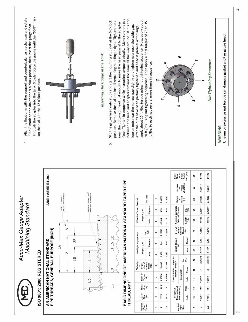
Bas
ic d
imen
sion
s of
the
Am
eric
an N
atio
nal S
tand
ard
Tape
r Pip
e Th
read
are
gi
ven
in in
ches
to 4
or 5
dec
imal
pla
ces.
Whi
le th
is im
plie
s a
grea
ter d
egre
e of
pre
cisi
on th
an is
ord
inar
ily a
ttain
ed, t
hese
dim
ensi
ons
are
the
basi
s of
th
e ga
uge
dim
ensi
ons
and
are
also
exp
ress
ed fo
r the
pur
pose
of e
limin
at-
ing
erro
rs in
com
puta
tions
. 2.
A
lso
leng
th o
f thi
n rin
g fr
om g
augi
ng n
otch
to s
mal
l end
of p
lug
gaug
e.
3.
Als
o pi
tch
diam
eter
at g
augi
ng n
otch
(han
dtig
ht p
lane
). 4.
A
lso
leng
th o
f plu
g ga
uge.
5.
Th
e le
ngth
L5
from
the
end
of th
e pi
pe d
eter
min
es th
e pl
ane
beyo
nd w
hich
th
e th
read
form
is in
com
plet
e at
the
cres
t. Th
e ne
xt 2
thre
ads
are
com
plet
e at
the
root
. At t
his
plan
e, th
e co
ne fo
rmed
by
the
cres
ts o
f the
thre
ad in
ter-
sect
s th
e cy
linde
r for
min
g th
e ex
tern
al s
urfa
ce o
f the
pip
e. L
5=L2
-2p.
6.
G
iven
as
info
rmat
ion
for u
se in
sel
ectin
g ta
p dr
ills.
7.
M
ilita
ry S
peci
ficat
ion
MIL
-P-7
105
give
s th
e w
renc
h m
akeu
p as
thre
e th
read
s fo
r siz
es 3
& s
mal
ler.
8.
Ref
eren
ce d
imen
sion
. “A”
= 2.
320”
FO
R S
TAN
DA
RD
3.5”
bol
t circ
le
8 ho
les,
tap
.500
-13
UN
C-2
B x
5/8
” m
in.
full
thre
ads
Not
e: M
ater
ials
and
spe
cific
atio
ns a
re s
ubje
ct to
cha
nge
with
out n
otic
e.
Pr
essu
re ra
tings
sub
ject
to c
hang
e du
e to
tem
pera
ture
and
oth
er e
nviro
nmen
tal c
onsi
dera
tions
.
7
ISO
900
1: 2
000
REG
ISTE
RED
Acc
u-M
ax G
auge
Ada
pter
M
achi
ning
Sta
ndar
d
A
N A
MER
ICA
N N
ATI
ON
AL
STA
ND
AR
D
PIPE
TH
REA
DS,
GEN
ERA
L PU
RPO
SE (I
NC
H)
BA
SIC
DIM
ENSI
ON
S O
F A
MER
ICA
N N
ATI
ON
AL
STA
ND
AR
D T
APE
R P
IPE
THR
EAD
, NPT
1
Nom
inal
Pi
pe
Thre
ad
O.D
. of
Pipe
(D
)
Thre
ad/
in.
(n)
Pitc
h of
Th
read
(P
)
Pitc
h di
a.
at
begi
n-ni
ng o
f ex
tern
al
thre
ad
(EQ
)
Han
dtig
ht e
ngag
emen
t Ef
fect
ive
Thre
ad E
xter
nal
Leng
th 2
(L1)
D
ia. 3
(E
1)
Leng
th 4
(L2)
Inch
Th
read
s In
ch
Thre
ads
1 2
3 4
5 6
7 8
9 10
11
2 2.
375
11.5
0.
0889
6 2.
2890
2 0.
436
5.01
2.
2962
7 0.
7565
8.
70
2.31
630
2.5
2.87
6 8
0.12
500
2.71
953
0.68
2 5.
46
2.76
216
1.13
75
9.10
2.
7906
2
Dia
. (E2
)
Nom
inal
Pi
pe
Size
Leng
th L
1 Pl
ane
exte
rnal
Th
read
(L2-
L1)
Wre
nch
Mak
eup
Leng
th fo
r In
tern
al T
hrea
d 7
Ove
rall
Leng
th
Exte
rnal
Th
read
(L
4)
Nom
inal
Com
plet
e Ex
tern
al T
hrea
ds
Hei
ght
of
Thre
ad
(H)
Incr
ease
D
ia./
Thre
ad
(0.0
625/
n)
Bas
ic
Min
or
Dia
. At
Smal
l En
d of
Pa
rt (K
O)
Leng
th (L
3)
Dia
. (E
3)
Inch
Th
rea
d In
ch
Thre
ad
Inch
Th
read
Le
ngth
(L
5)
Dia
. (E
5)
1 12
13
14
15
16
17
18
19
20
21
22
23
24
2 0.
3205
3.
69
0.26
09
3 2.
2527
2 0.
3017
3.
47
1.05
82
0.58
26
2.30
543
0.06
957
0.00
543
2.19
95
2.5
0.45
55
3.64
0.
2500
2
2.70
391
0.43
37
3.47
1.
5712
0.
8876
2.
7760
0 0.
1000
0 0.
0078
1 2.
6195
Vani
sh T
hrea
d (V
)
AN
SI /
ASM
E B
1.20
.1
4
4.
Align the flo
at arm
with
the supp
ort a
nd cou
nterbalance mechanism
and
rotate
“50%
” mark on
the dial to
the 9 o’clock po
sition, th
en insert th
e gauge flo
at
through the adapter into the tank. Slowly ro
tate th
e gauge un
til th
e "50%
" mark
on th
e dial is at the
12 o’clock po
sition.
Inserting Th
e Gau
ge in
the Ta
nk
5.
Slip th
e gauge he
ad onto stud
s and
start the
mou
nting stud
nut at the
6 o’clock
position. Rem
ove the dial and
install rem
aining
nuts finger‐tig
ht. Tighten nu
ts
near th
e bo
ttom
of h
ead just eno
ugh to m
ake the he
ad parallel to the adapter
face. Tighten in se
quen
ce while increasin
g torque
gradu
ally. Make sure th
e gap
be
tween the he
ad and
adapter re
mains th
e same all the
way aroun
d. If it is n
ot,
loosen
nuts n
ear the
narrow gap
slightly and
tighten nu
ts near the
wide gap.
After the
nuts h
ave be
en partia
lly tightene
d and he
ad is parallel w
ith flange,
apply abou
t 10 ft./lbs. to
rque
usin
g nu
t tighten
ing sequ
ence. Now
, app
ly abo
ut
20
ft./lbs. usin
g nu
t tighten
ing sequ
ence. Then
app
ly a final torqu
e of 25 to 35
ft./lbs. to
each nu
t several m
ore tim
es in
sequ
ence.
Nut Tightening Sequ
ence
1 2
3
4
5 6
7
8
WAR
NING
Une
ven or excessive
nut to
rque
can
dam
age gasket and
/ or gau
ge head.

5
6. In
stallatio
n Inspectio
n Purge th
e vessel if necessary. Pressurize it to at least one
‐third th
e rated
ta
nk pressure if it is a pressure vessel. Che
ck fo
r leakage between he
ad and
adapter a
nd aroun
d each m
ounting bo
lt he
ad. Over‐tig
hten
ing of m
ounting
bolts m
ay cause cracks o
r warp the he
ad. If no
leaks o
r other defects
are detected, fill the vessel.
CAUTION
The ba
ck of the
dial cha
mbe
r must b
e seated
in th
e gauge he
ad and
all
brackets to
uching
the dial cha
mbe
r with
out rocking
. If they do no
t, carefully
bend
the bracket a
rms forw
ard un
til even.
8. Attach dial chambe
r—4” DOT Mod
el at the
9 and
3 o’clock position
, 4” Stationary
mod
el at the
9,12 and 3 o’clock po
sition as sh
own.
7. Install dial m
ounting brackets—4” DOT mod
el at the
9 and
3 o’clock position
s,
8” Statio
nary at the
9, 12, and
3 o’clock position
as sho
wn
ME930
1 2
ME940
1
3
2
1 2
ME930
ME940
3
2
1
6
WAR
NING
DO NOT TEST THE FLOAT
FOR LEAK
AGE BY
ANY MEA
NS
If the dial indicates a
lower liqu
id level tha
n wha
t is kn
own, th
en th
e gauge
float m
ay be leaking an
d may be filled with
liqu
id. Place the removed
floa
t in
a safe, isolated an
d well‐v
entilated
area to give the LP Gas or N
H3 a chan
ce to
diffuse. W
ith th
ese liq
uefie
d gases an
d othe
r sim
ilar p
rodu
cts, a dan
ger o
f flo
at explosion
exists d
ue to
liqu
id or g
as expan
sion
resulting
from
warming a
float from
any
sou
rce.
Precau
tions Regarding
Rem
oval of G
auge
If gauge removal app
ears necessary, this sho
uld on
ly be do
ne by a qu
alified
individu
al
unde
r com
petent su
pervision
. Make sure pressure is en
tirely blow
n do
wn and wind
cann
ot carry fu
mes near o
pen flames.
Fire Hazard Warning
A hazard of fire
or e
xplosio
n may exist if prope
r metho
ds are not used whe
n installing
or re
moving gauge from
vessels containing
pressurize
d liquid or gas, flammable liqu
ids,
oxidize
rs, N
H3 or LP Gas.
Removing the Gau
ge
Whe
n removing gauges, do no
t strain or fo
rce the parts, especially in
lining
up the
coun
terbalance. A
fter m
ounting stud
nuts h
ave be
en re
moved
, rep
lace th
e dial cham‐
ber a
nd slow
ly ro
tate th
e gauge left or right until the po
inter is a
t the
50%
level. In
this
position, th
e coun
terbalance will be parallel to the supp
ort a
rm and
can
be easily with
‐draw
n through the op
ening.
9. In
stallatio
n Inspectio
n Che
ck fo
r pointer m
ovem
ent a
fter 5% fu
ll, prio
r to filling to th
e de
sired
level.
NOTE
Th
e Ac
cu‐M
ax dial face is Argon
filled an
d factory sealed
to prevent m
oisture
and fogging. Do no
t rem
ove dial fa
ce screw
s other th
an th
ose show
n as th
is
may break
dial seal releasing
the Argo
n.
Recommended