B O N N E V I L L E P O W E R A D M I N I S T R A T I O N
AccidentPrevention
Manual
Effective January 1, 2013
Testing interval
2012 2013 2014
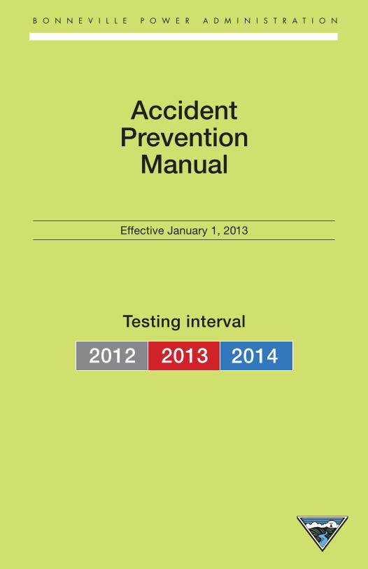
BPA Safety Motto
No job is so important and no service so urgent that we cannot take time to perform our work safely.
i January 2013
BONNEVILLE POWER ADMINISTRATION
ACCIDENT PREVENTION MANUAL
January 1, 2013

ii January 2013
iii January 2013
Accident Prevention ManualTable of Contents
REFERENCESWork Standards and Guides viOperating Bulletins viiAPM Revision Tracking viiiForeword ixSafety Committee Organization xi
RULES SECTION
CHAPTER ONERule Section PageA-1 Access to BPA Energized Facilities R1A-2 Apparel R5B-1 Barriers & Guards, Electrical R7B-2 Barriers & Guards, Non Electrical R8C-1 Conductive Devices, Restrictions of R8C-2 Coupling Capacitors and Bushing Potential Devices R8C-3 ConfinedSpaces R8C-4 Current Transformer Secondary R9C-5 Crossing, Pole-To-Pole, Over A Single Arm R9E-1 Excavation R10E-2 Explosives, Handling and Use of R10E-3 Eye and Face Protection R11F-1 Fall Protection R13F-2 Flammable Liquids R13F-3 Fiber Optics R13G-1 Grounds, Portable Protective R14G-2 Grounds, Portable Protective, Voltage Testing R17G-3 Grounds, Portable Protective, Where Installed R17G-4 Grounds, Portable Protective, Installation and R18 Removal of
G-5 Grounds, Portable Protective, For Each Clearance R20G-6 Grounding, Portable Protective, Special Requirements R22G-7 Grounds, Portable Protective, Capacitors R37
iv January 2013
Rule Section PageG-8 Grounding, Portable Protective, Shunt Reactors and Transformers R38G-9 Grounds, Portable Protective, Static Wire R38G-10 Grounding of Equipment, Tools, and Metallic Cables R39G-11 Grounds, Portable Protective, Fiber Optics R41G-12 Grounds, 1/0 URD Grounds R41H-1 Head Protection R42H-2 Hearing Protection R43I-1 IdentificationofCircuits R43J-1 JobBriefing R43L-1 Ladders, Securing of R44L-2 Low Voltage Circuit, Work on R44L-3 Lockout/Tagout R45M-1 Minimum Approach Distance R47P-1 Power Equipment R49R-1 Rope, Wire R49R-2 Rope, Synthetic R50R-3 Rigging, Equipment R50R-4 Radio Frequency Exposure, for Personal R52 Communication Systems R-5 Responsibililties R53
• Employer, Supervisor, Employee R-6 Mobile Radio Frequency Assignment R53S-1 Safety Watchers - General R54S-2 SafetyWatchersForQualifiedElectricalEmployees R55S-3 Safety Watchers for Restricted Electrical R56 and Nonelectrical Workers S-5 Signals, Hand Signals for Crane Work and Line Work R58S-6 Switching & Clearance Procedure R65S-7 Switches, Isolating Devices, Energized, Restrictions on R65S-8 Safety Restraints, Vehicle R65T-1 Testing Intervals of Tools and Equipment R66W-1 Welding R67
v January 2013
CHAPTER TWORule Section PageA-1 Access to BPA Energized Facilities R69H-1 Head Protection R73S-4 Safety Watchers for Contractor Employees R73S-6 Switching and Clearance Procedure R74
PROCEDURES SECTION
CHAPTER ONE Page-- Switching and Clearance Procedure P1
CHAPTER TWO Page-- Switching and Clearance Procedure P58
-- Color Addendum A1-- Glossary of Special Terms and Phrases D1-- Electrical Contact Accident Protocol E1-- Accident Reporting Process F1-- SF6 Accident Protocol G1
vi January 2013
WORK STANDARDS AND GUIDES
WORKSTANDARDS & APM PAGEGUIDES RULE NUMBERBPA II A-1 R3BPA BPA-WS-11-6 A-2 R5BPA BPA-WS-7-3-(3.2) B-1 R7SubMaint SM-STD-17-1-2 B-1 R7 BPA BPA-WS-9-7 C-2 R8BPA BPA-WS-11-1 C-3 R8BPA BPA-WS-9-1 C-4 R9BPA BPA-WS-11-8 E-1 R10 TLM I.B.2 E-2 R10BPA BPA-WS-11-2 F-1 R13BPA BPA-WS-9-3 F-3, G-11 R13, R41TLM I.A.3 G-1 R15BPA BPA-WS-6-3 G-6 R22BPA SM-STD-13-1-14 G-7 R37SubMaint SM-STD-13-1-15 G-10 R39TLM I.A G-10 R39BPA BPA-WS-9-3 G-11 R41 BPA BPA-WS-11-6 L-2 R44BPA BPA-WS-8-1 L-3 R45OB #2 VIII L-3 R45Liveline Manual M-1 R47BPA BPA-WS-5-1 M-1 R48BPA BPA-WS-11-5 R-4 R52BPA BPA-WS-6-4 T-1 R66BPA BPA-WS-7-1 T-1 R66BPA BPA-WS-7-2 T-1 R66
vii January 2013
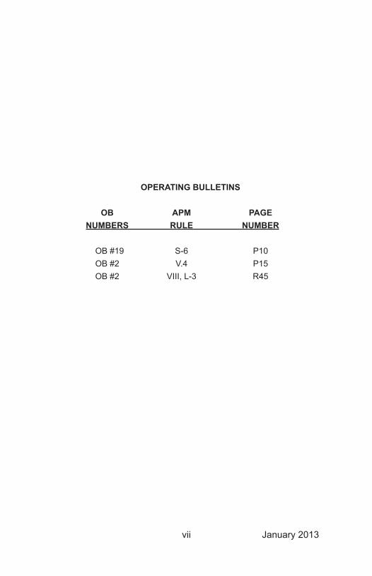
OPERATING BULLETINS OB APM PAGE NUMBERS RULE NUMBER
OB #19 S-6 P10 OB #2 V.4 P15 OB #2 VIII, L-3 R45

viii January 2013
APM REVISION TRACKING
Use this page to track revisions to the APM. Future revisions will have a revision # and date at the bottom.
PAGE REVISION # DATE
ix January 2013
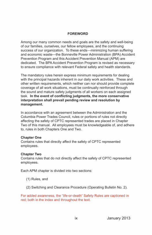
FOREWORD
Among our many common needs and goals are the safety and well-being of our families, ourselves, our fellow employees, and the continuing success of our organization. To these ends—minimizing human suffering and economic waste—the Bonneville Power Administration (BPA) Accident Prevention Program and this Accident Prevention Manual (APM) are dedicated. The BPA Accident Prevention Program is revised as necessary to ensure compliance with relevant Federal safety and health standards.
The mandatory rules herein express minimum requirements for dealing with the principal hazards inherent in our daily work activities. These and other written requirements, which neither can nor should provide complete coverage of all work situations, must be continually reinforced through the sound and mature safety judgments of all workers on each assigned task. In the event of conflicting judgments, the more conservative interpretation shall prevail pending review and resolution by management.
In accordance with an agreement between the Administration and the Columbia Power Trades Council, rules or portions of rules not directly affecting the safety of CPTC represented trades are placed in Chapter Two of this manual. All employees must be knowledgeable of, and adhere to, rules in both Chapters One and Two.
Chapter OneContains rules that directly affect the safety of CPTC represented employees.
Chapter TwoContains rules that do not directly affect the safety of CPTC represented employees.
Each APM chapter is divided into two sections:
(1) Rules, and
(2) Switching and Clearance Procedure (Operating Bulletin No. 2).
For added awareness, the “life-or-death” Safety Rules are captioned in red; both in the index and throughout the text.

x January 2013
APM rules may only be adopted or revised by the Central Safety and Health Committee (CS&HC). Rule changes become effective on the issue date of the APM except in special circumstances, and then by a Safety Alert or other method deemed appropriate by the CS&HC.
TheSafetyOfficewillprovideadvice,information,andsupporttoallmanagers,supervisors,andemployeestoenableBPAtofulfillitsresponsibilities of providing a workplace free from all recognized safety and health hazards.
xi January 2013
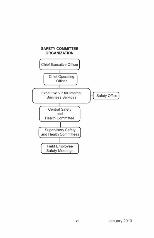
Chief Executive Officer
Chief OperatingOfficer
Executive VP for InternalBusiness Services
Supervisory Safetyand Health Committees
Central Safetyand
Health Committee
Field EmployeeSafety Meetings
Safety Office
SAFETY COMMITTEEORGANIZATION

xii January 2013
This Page Intentionally Left Blank

January2013
CHAPTER ONE

January2013
This Page Intentionally Left Blank
xiv
R 1 March 2011
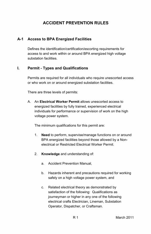
ACCIDENT PREVENTION RULES A-1 Access to BPA Energized Facilities
Defines the identification/certification/escorting requirements for access to and work within or around BPA energized high voltage substation facilities.
I. Permit - Types and Qualifications
Permits are required for all individuals who require unescorted access or who work on or around energized substation facilities. There are three levels of permits: A. An Electrical Worker Permit allows unescorted access to
energized facilities by fully trained, experienced electrical individuals for performance or supervision of work on the high voltage power system.
The minimum qualifications for this permit are: 1. Need to perform, supervise/manage functions on or around
BPA energized facilities beyond those allowed by a Non-electrical or Restricted Electrical Worker Permit.
2. Knowledge and understanding of:
a. Accident Prevention Manual, b. Hazards inherent and precautions required for working
safely on a high voltage power system, and c. Related electrical theory as demonstrated by
satisfaction of the following: Qualifications as journeyman or higher in any one of the following electrical crafts Electrician, Lineman, Substation Operator, Dispatcher, or Craftsman.
R 2 March 2011
3. Experience of one year minimum in a position with knowledge requirements where the applicant received, issued or worked under at least three Clearances on the BPA or equivalent power system (names of holders and dates of Clearances along with identification of system, if other than BPA, are required).
B. A Restricted Electrical Worker Permit allows unescorted
access to energized facilities by individuals trained and required to perform specific, selective craft or technical functions involving work that could have an effect on the power system. Work involving the possibility of inadvertent contact with high voltage parts or the violation of Minimum Approach Distances must be performed under the direct, on-site supervision of a Qualified Electrical Employee. The minimum qualifications for a Restricted Electrical Worker Permit are: 1. Need to perform duties on or around BPA energized facilities
beyond those allowed by a Non-electrical Worker Permit. 2. Knowledge and understanding of:
a. BPA Accident Prevention Manual, b. Hazards inherent and precautions required for working
safely on applicable parts of a high voltage power system.
3. Job title that is included in or closely related to an electrical
craft or function, such as: Craftsman, Line Equipment Operator, Groundman, Electrical Riggers, Electrical Apprentice, or Electrical Trainees.
C. A Non-electrical Worker Permit allows unescorted access to
energized facilities by individuals who have received appropriate instructions and have demonstrated a level of understanding necessary to safely move about in energized substations.
R 3 March 2011
This permit allows performance of predefined work not affecting electrical operation of the power system. The minimum qualifications for this permit are: 1. Need to perform non-electric duties in or around BPA
energized facilities. 2. Knowledge and understanding of BPA’s Rules of Conduct
in energized substations. D. Non-permitted individuals requiring entry to, movement within
or who work on or around energized substation facilities will require an escort at all times by an appropriately permitted employee while in the facility. Employees who provide access to energized high voltage facilities to others not having a permit are responsible for ensuring that they are properly escorted at all times while in the facility.
II. Permits for Employees
Employees requiring unescorted access to or work on or around energized facilities must meet the minimum qualifications and examination/switchyard orientation requirements. [Reference BPA Work Standard II, Substation Security]
III. Clearance Certification
A. A Restricted Clearance Certification allows employees who
hold a Restricted Electrical Worker Permit to take Clearances and Hold Orders on BPA and foreign utility transmission lines adjacent to facilities being constructed. This is for purposes of addressing/controlling hazards of induction from, or accidental contact with adjacent energized lines. Hold Orders and/or Clearances issued for these purposes do not provide access for work or contract inspection on these lines.
R 4 March 2011
B. A Standard Clearance Certification allows employees who hold
an Electrical Worker Permit to: (1) take Clearances and Hold Orders, without predefined restrictions, on high voltage facilities, and (2) to issue Clearances and Hold Orders in accordance with provisions of the Switching and Clearance Procedures.
IV. Withdrawal of Permits and Clearance Certifications
Withdrawal of permits and/or Clearance certifications may be affected at any time by a responsible management official. Causes for withdrawal include, but are not limited to:
1. Demonstrated lack of knowledge or unwillingness to follow
safe work practices, 2. Violation of established safety rules or procedures, 3. Documented cases showing lack of sound and mature safety
judgment, 4. Breach of substation security.
V. Clearance Certification and Permits Directory
A current electronic list of employees holding Permits and Clearance Certifications and a list of Contractor Permits is maintained by Substation Operations, TOZ/AmpN1. This list is updated as needed and distributed to System Control Centers. Verification can be accomplished by contacting Substation Operations Group or a System Control Center.
R 5 January 2013
A-2 ApparelClothing appropriate for the job shall be worn. Full-length pants and shirts with full or half sleeves are required when engaged in field, shop or industrial activities. Shorts, tank tops or similar attire is not considered appropriate apparel. Supervisors have the responsibility for assuring that appropriate clothing and apparel is worn. Employees have the responsibility of wearing items that prevent exposure to known or expected hazards.
Loose, dangling clothing or accessories shall not be worn where there is possibility of contact with moving machinery.
When work is performed within reaching distance of exposed energized parts, the wearing of conductive objects such as key or watch chains, rings, wrist watches, bracelets, or other conductive objects is prohibited.
Appropriate footwear that provides adequate support and protection to the foot, toes and ankles for the work being performed shall be worn. Lace-up, over the ankle boots with rigid sole and heel meeting ASTM F 2413-05, Class 75 with EH rating shall be worn in all work areas where hard hats are required and other areas as determined by a supervisor. Supervisors have the responsibility for assuring that appropriate footwear is worn. Employees have the responsibility to wear appropriate footwear for the job.
When performing transmission line work, specialized footwear (e.g., hot boots, etc.) appropriate for the work practice may be worn.
The wearing of clothing and footwear made from acetate, nylon, polyester, or rayon either alone or in blends (unless labeled with an Arc Thermal Protection Value of 8 cal/cm2 or greater) is prohibited when an employee may be exposed to the hazards of electric arcs or flames. Footwear made of leather provides an appropriate level of ATPV protection.
When work is to be performed on or near energized circuits where the phase-to-phase or phase-to-ground voltage is 600V or less, Arc Flash Personal Protective Equipment shall be utilized as specified in BPA Work Standard BPA-WS-11-6, Arc-Flash Personal Protective Equipment.
The following items of personal protective clothing, accompanied by brief statements of purpose, are either provided or subsidized by the Administration. Supervisors are responsible for obtaining and requiring the use of PPE as necessary for safe performance of the work.
R 6 January 2013
1. Appropriate gloves: Gloves are provided for job activities where hand protection is required.
2. Safety shoes: Employees are reimbursed, in a negotiated amount,
for purchase of approved safety shoes meeting ASTM F 2413-05, Class 75 with EH rating for wear in work areas or activities where protective footwear is required. Supervisors may also require, or the employee may elect built-in metatarsal protection in shoes meeting the above ASTM standard.
3. Additional items: Personal protective equipment is defined under appropriate APM Rules, i.e.; Hard Hat requirement (H-1), Hearing Protection (H-2), and Eye and Face (E-3). Special-purpose equipment, used in chain saw operations, specified work on or around high voltage equipment, high pressure air systems, and for handling of hazardous material, is defined in applicable Standards, Operating Bulletins, and BPA Safety and Health programs.
4. Arc flash personal protective equipment appropriate for the hazard/risk category shall be utilized.
R 7 January 2013
B-1 BARRIERS & GUARDS, ELECTRICALBarriers are used to prevent contact with energized parts. Line/insulator covers and similar protective devices, properly installed, allow work within the Minimum Approach Distance as stated in Rule M-1. These devices must be installed and removed with hot line tools or under the protection of a Clearance. Approved insulated barriers shall be inspected before each use.
Guards are used to maintain Minimum Approach Distances which include the margin for inadvertent movement.
Devices such as fencing, when installed under the supervision of a Quali-fied Electrical Employee, may be used to separate a work area in the switchyard from energized sections.
Areas guarded with red-and-white rope shall not be entered! This guard is used on the ground and in structures to prohibit all persons from enter-ing the energized zone.
Red-and-white rope guards must be installed and removed by or under the direction of the Qualified Electrical Employee in charge of the job.
Areas guarded with yellow-and-black rope may be entered by Qualified Electrical Employees. Entry by others is prohibited unless accompanied by a Qualified Electrical Employee. Yellow-and-black rope guards must be installed under the supervision of a Qualified Electrical Employee. This guard may be removed by others upon approval of the responsible Qualified Electrical Employee.
Red-and-white and yellow-and-black rope shall not be used for any purpose except electrical guards. No other rope color shall be used for electrical guards.
Special-purpose electrical barriers and guards must be approved by the BPA Safety Office. The Safety Office may give approval, with continued use subject to review by the Central Safety and Heath Committee. [Reference BPA Work Standard, BPA-WS-7-3-(3.2), Installations with Reduced Electrical Clearances; Substation Maintenance and Guide, SM-STD-17-1-2, Special Purpose Electrical Barriers or Guards]
R 8 January 2013
B-2 BARRIERS & GUARDS, NON ELECTRICALBarriers and guards, known to be adequate for other circumstances, must also be utilized in protecting against mechanical, environmental, and other nonelectrical hazards such as open excavations or manholes. Environmentally contaminated areas shall be guarded and identified by signs and may be entered only by persons who have been trained to protect themselves from the hazards of the contaminants present.
C-1 CONDUCTIVE DEVICES, RESTRICTIONS OFPortable metal ladders are not permitted in energized substation yards or for use in any situation where there is danger of contact with energized lines or equipment.
Conductive objects such as metal tapes, surveyor chains, fish tapes, and center-line wire may be used only when restrained by adequate methods, as determined by a Qualified Electrical Employee, to prevent electrical contact in the event of slippage or breakage at any point.
C-2 COUPLING CAPACITORS AND BUSHING POTENTIAL DEVICES
Work in the base units of this equipment, other than tuning or voltage adjustments, shall be performed under the protection of a Clearance as outlined in BPA Work Standard BPA-WS-9-7, Bushing PDs, Coupling Caps & Line Tuning Units.
C-3 CONFINED SPACESSome confined spaces require a confined space entry permit (BPA Form 5480.10e) before entering (i.e.; storage tanks and 500 kV GIS Bus Runs). Other confined spaces and enclosed spaces do not require permits (i.e.; oil PCBs and manholes) but special precautions must be followed as outlined in BPA Work Standard BPA-WS-11-1, Confined Space. A confined space is one which:
1. Has a limited or restricted opening for entry or exit.2. May contain or generate a toxic or explosive atmosphere.3. May be oxygen deficient.4. Is not intended for continuous occupancy.5. May contain electrical/mechanical hazards.
R 9 January 2013
C-4 CURRENT TRANSFORMER SECONDARYThe CT secondary circuit shall not be opened while the primary is energized, due to the possible development of a high secondary voltage.
When work is to be performed on CT circuits that are normally in service, the senior Test and Energization Engineer (T&E) or a System Protection and Control (SPC) employee shall lead the job briefing and approve any wiring work on CT circuits, including the shorting of CTs.
All work shall be performed in accordance with BPA Work Standard BPA-WS-9-1, Servicing and Testing Current Transformers.
C-5 CROSSING, POLE-TO-POLE, OVER A SINGLE ARMCrossing from one pole to another over a single crossarm is permitted only when the circuit is de-energized and with the use of a safety line rigged from one pole to the other.
R 10 January 2013
E-1 EXCAVATIONThe estimated location of utility installations or any other underground installation that may be encountered during excavation work shall be determined prior to opening an excavation.
Excavations shall not be entered by personnel until the following measures are taken by a competent person prior to the start of work and as needed throughout the shift:
1. Identify site specific hazards including surface encumbrances and remove or protect as necessary.
2. Evaluate soil conditions and select appropriate protective systems.3. Ensure that provisions for safe access into and out of the excavation
are in place.4. Ensure a site specific emergency action plan is in place and required
equipment is available.
Prior to entry into excavations 4 feet or more in depth an Excavation Entry Permit completed by the competent person and approved by the supervisor shall be posted on site.
Excavations 5 feet or more in depth shall not be entered unless sloped to the appropriate angle of repose, shored or shielded.[Reference BPA Work Standard BPA-WS-11-8, Excavation and Trenching Policy]
E-2 EXPLOSIVES, HANDLING AND USE OFBPA personnel shall not use explosive devices other than implosive fittings and their components. Only properly trained personnel holding a current certification shall be allowed to perform implosive operations. Before a detonation takes place the Blaster in charge shall ensure that all personnel are at a minimum of 200 feet away from the detonation site. Hearing pro-tection is required for all personnel during each implosive operation and shall consist of BOTH soft earplugs with a minimum NRR (noise reduction rating) of 33 AND ear muffs with a minimum NRR of 28.
All handling, use, storage, and transportation of explosives shall be done in accordance with TLM Standards and Guides, I.B.2, IMPLO Fittings, Storage, Handling and Use.
R 11 January 2013
TABLE 1
Work Activity Protective DevicesAcids, caustic, handling 2, 3 (use in combination for severe exposure)Air hammer 1 (add 3 for severe exposure)Arc flash 3Brazing, torch 4Buffing 1Chipping 1 (add 3 for severe exposure)Cutting, torch 4 (for severe exposure use 5)Fiber Optics 1, 2Grinding 1 (add 3 for severe exposure)Molten metals 4 (3 over 4 or 6 optional)Powder actuated tools 1 (add 3 for severe exposure)Soldering, hard 4Soldering, soft/electronic 1, 2, 3Stud gun 1 (add 3 for severe exposure)Sun glare 1, 6Switching, power system 6Torch, heating 4Welding, torch 4Welding, electric arc 5Welding, electric spot 4, 6 (add 3 for severe exposure)Wire brushing 2Wood chipping 1 (2 or 3, screen lens permitted, over 1 optional)
E-3 EYE AND FACE PROTECTIONApproved protective devices shall be worn while performing or while in the proximity of activities which present a recognized hazard to eyes and face.
Approved eye protection shall be worn whenever there is danger of injury from electrical arcs or flying objects resulting from accidental electrical contact while working on energized electrical circuits or equipment.
The following tables illustrate minimum requirements for compliance with eye and face protection (Reference Table 2 for description of protective devices listed by number in Table 1).
R 12 January 2013
TABLE 2
1. Protects against frontal, high impact hazards (safety spectacles, plain and prescription, equipped with side shields; available in clear or shaded).
2. Protects against light impact, dust, and chemical splash (chemical use requires model equipped with hooded vents; fits over safety spectacles).
3. Protects against light impact and chemical splash (for severe exposures, use in combination
with 1).
Arc flash protection if so rated.
4. Protects against torch brazing, hard soldering, light cutting and welding (fits over safety spectacles).
5. Protects against radiant energy from electric arc welding and heavy torch cutting (helmet or sock hood are only types permitted for arc welding both must be used in combination with 1).
6. Protects against visual hazards or “flash burns” from power system arc—required for switching on high voltage power system.
R 13 January 2013
F-1 FALL PROTECTIONApproved fall protection shall be used when working aloft above 4 feet on all towers, poles, and similar structures.
Employees working aloft in an aerial lift or on platforms supported by lift equipment shall wear a full body harness and be attached with either a retractable or shock absorbing lanyard.
During climbing activities above 4 feet, at least two qualified climbers shall be present. Unqualified climbers must remain 100 percent attached. [Reference BPA Work Standard BPA-WS-11-2, Fall Protection].
F-2 FLAMMABLE LIQUIDSFlammable liquids within 70 feet of conductors energized at voltages of 345 kV and higher shall not be transferred from one metal container to another unless the two have been electrically bonded together to eliminate arcing.
F-3 FIBER OPTICSWhen working with fiber optics, the use of personal protective equipment is required to prevent injury. Eye protection shall be worn when splicing glass fiber (see APM Rule E-3). Care should be taken during the cleaving process to protect the eyes and the body from broken glass pieces.
CAUTION: Never look into the end of an optical fiber. The laser light that may be present is invisible and eye damage may occur.
Chemicals that are present in fiber or the chemical used to clean fiber may require the use of hand protection. Consult the Material Safety Data Sheet (MSDS) for proper use of personal protective equipment. [Reference BPA Work Standard BPA-WS-9-3, Fiber Optics]
R 14 January 2013
G-1 GROUNDS, PORTABLE PROTECTIVE, FOR WORK ON DE-ENERGIZED CIRCUITS
Protection from electric shock is obtained by using approved portable protective or discharge grounds to short all conducting parts to a common ground.
Portable protective grounds shall be applied before a worker or equipment contacts or comes within the Minimum Approach Distance of the circuit. Portable protective grounds shall be installed to protect persons from the hazards of accidental energization from any source of power system energization. Such sources of power system energization include:
• Accidental energization from the power system, power lines or other energized high voltage equipment by accidental contact or accidental closing of an isolating device.
• Backfeed through station service or potential transformers.
• Remote lightning causing a fault on an adjacent circuit or a strike to the deenergized one.
Note: Portable protective grounds may not provide complete personal protection for close-in strikes. Work shall be suspended and personnel shall stay in the clear during times that lightning is within sight or sound.
Portable protective ground leads shall be of flexible 2/0 copper cable or equivalent. Except: (1) permanently installed ground switches on gas insulated equipment, capacitors, and reactors; and (2) grounding plugs, at least equal in rating to the required portable protective ground lead(s) and designed for the metal-clad switch-gear involved, may be used in lieu of portable protective grounds; and (3) 1/0 URD grounds for grounding, where appropriate, of underground residential distribution (URD) equipment.
R 15 January 2013
Any reference to portable protective grounds shall mean an adequate number of ground leads to effect a visible three-phase short and ground on the circuit. Visible grounding may be accomplished through conductive parts of equal current carrying capacity as the protective grounds require, but shall not be effected through a ground mat or other concealed conductors, except at series capacitors per rule G-7; Grounds, Portable Protective, Capacitors.
In substations, when portable protective grounds have been installed at all possible sources of energization from the high voltage power system, separated circuit parts in the work area to be contacted during the course of the work shall be bonded and tied to ground by application of either discharge grounding cables or portable protective grounds.
All conductive parts in the work area that may be contacted during the course of the work shall be at the same potential and shall be tied to a common ground.
Before cutting or separating any part of the protective grounding circuit that could expose a worker to a possible difference of potential, the separated components shall be bonded together and tied to ground.
The Clearance Holder shall identify all parts of the protective grounding circuit prior to the installation of portable protective grounds to ensure that a thorough understanding of the specific grounding circuit exists by all crew members prior to the start of work.
When grounding overhead transmission lines where workers are not protected by a ground mat, grounding procedures and measuring of step-and-touch voltages shall be done in accordance with TLM Standards and Guides I.A.2., Grounding, BPA Equipment and Structures; and I.A.3., Protection of Electrical Workers from Induced Currents and Voltages.

R 16 January 2013
An exception to the AC three-phase grounding requirement may be made when all of the conditions listed below are met. Then only those phases to be worked on during the course of the project need to be grounded.
• The circuit is a transmission line structure located outside of a substation.
• The circuit is normally energized at 500 kV or more.• The work plan does not involve work on all three phases.• The installation and/or removal of protective grounds creates a
higher than normal potential hazard to the workers involved (e.g.; weather, ice, high induced voltage requiring the use of a vacuum bottle for ground removal, etc.).
• All phases to be worked on during the course of the project will be grounded at the beginning of the work.
Ground rods shall be of steel, copper, or copper-clad steel not less than 5/8 inch in diameter or less than 6 feet in length and shall be placed in the ground to a depth which shall assure adequate grounding.
Portable protective grounding on HVDC may be applied only to the pole being worked on if the work plan does not require working within the MAD of the other pole.
R 17 January 2013
G-2 GROUNDS, PORTABLE PROTECTIVE, VOLTAGE TESTING
Immediately before applying grounds, a voltage test shall be made on each phase with a “voltage detector” instrument that produces both a visible and audible signal.
If there is any indication that the circuit being tested is still energized at full line potential, the circuit shall be treated as energized. Do not assume it is caused by induction from nearby power lines. Do assume that the circuit is still energized and take proper precautions, i.e. notify the dispatcher, recheck your circuit identification, maintain the Minimum Approach Distance, and DO NOT apply portable protective grounds until assured that the circuit is indeed de-energized.
The voltage test shall be performed in accordance with BPA Work Standard VI.B., Voltage Testing Procedures.
G-3 GROUNDS, PORTABLE PROTECTIVE, WHERE INSTALLED
Before workers come within the Minimum Approach Distance of any high voltage circuit part not protected by special barriers, as defined in Rule B-1, that part must be de-energized and be grounded at each separate or separable circuit part in accordance with Rule G-1.
Portable protective grounds shall be installed as close to the work being performed as practical, and in such a manner as not to be disturbed during the course of the work.
No disconnect switch, power circuit breaker, transformer *, wave trap, fuse, or current limiting reactor** shall be part of the protective grounding circuit.
*Note: Does not apply to a visible single-turn primary such as in a “donut” CT circuit.
**Note: Does not apply to current limiting reactors installed on shunt capacitor installations where the neutral of the shunt capacitor is grounded in accordance with Rule G-7. A minimum of a discharge grounding cable shall be installed between the current limiting reactor and the shunt capacitor bank in addition to the Portable Protective Grounds installed at the source side of the current limiting reactor.
R 18 January 2013
G-4 GROUNDS, PORTABLE PROTECTIVE, INSTALLATION AND REMOVAL OF
All ground leads from each ground set shall be connected at the ground end before any conductor end from that same ground set is connected to de-energized electrical parts.
Workers should avoid handling or contacting the ground lead while the conductor end is being installed or removed. During removal, all ground leads of each ground set shall be disconnected from the conductor end first. The conductor ends from that same set shall be moved to a point in the clear of the de-energized electrical parts before any ground lead from that same ground set is removed from the ground end.
Exception: On transmission towers where grounds are to be installed aloft, it is permissible to install or remove both ground and conductor ends on each phase prior to workers moving location. The conductor end shall be connected and disconnected with live line tools.
In some cases it may be difficult to remove a ground lead with a live line tool (such as one installed during construction). In these cases, a second ground lead may be installed alongside the original one. The original one may then be removed by hand, and the second or remaining ground lead removed with a live line tool.
The minimum crew for installing portable protective grounds consists of one of the following:
• Two Qualified Electrical Employees, or • One Qualified Electrical Employee and an electrical worker (electrical
apprentice, journeyman in training, temporary electrical worker) who has been approved by both the supervisor and the Qualified Electrical Employee involved.
NOTE: When on line structures, the required electrical workers must be in the structure and be assisted by adequate help on the ground.
When applying portable protective grounds on transmission lines, the required electrical workers shall be in the structure and/or an aerial lift device and be assisted by adequate help on the ground. These required electrical workers shall work closely together observing each other testing for voltage and applying portable protective grounds.

R 19 January 2013
Additional portable protective ground sets may be installed on the same circuit and all sets may be removed by one Qualified Electrical Employee and one other worker.
R 20 January 2013
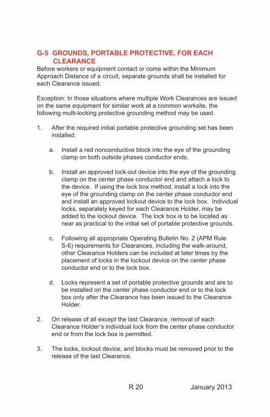
G-5 GROUNDS, PORTABLE PROTECTIVE, FOR EACH CLEARANCE
Before workers or equipment contact or come within the Minimum Approach Distance of a circuit, separate grounds shall be installed for each Clearance issued.
Exception: In those situations where multiple Work Clearances are issued on the same equipment for similar work at a common worksite, the following multi-locking protective grounding method may be used.
1. After the required initial portable protective grounding set has been installed:
a. Install a red nonconductive block into the eye of the grounding clamp on both outside phases conductor ends.
b. Install an approved lock-out device into the eye of the grounding clamp on the center phase conductor end and attach a lock to the device. If using the lock box method, install a lock into the eye of the grounding clamp on the center phase conductor end and install an approved lockout device to the lock box. Individual locks, separately keyed for each Clearance Holder, may be added to the lockout device. The lock box is to be located as near as practical to the initial set of portable protective grounds.
c. Following all appropriate Operating Bulletin No. 2 (APM Rule S-6) requirements for Clearances, including the walk-around, other Clearance Holders can be included at later times by the placement of locks in the lockout device on the center phase conductor end or to the lock box.
d. Locks represent a set of portable protective grounds and are to be installed on the center phase conductor end or to the lock box only after the Clearance has been issued to the Clearance Holder.
2. On release of all except the last Clearance, removal of each Clearance Holder’s individual lock from the center phase conductor end or from the lock box is permitted.
3. The locks, lockout device, and blocks must be removed prior to the release of the last Clearance.

R 21 January 2013
4. The portable protective ground set may then be removed and the Clearance released following normal procedures.
R 22 January 2013
G-6 GROUNDING, PORTABLE PROTECTIVE, SPECIAL REQUIREMENTS
I. BACKGROUND
Multiple portable protective grounds are required in many locations on the BPA system. They must be capable of carrying high magnitude fault cur-rent until the fault is cleared by protective relays and one or more power circuit breakers. The use of multiple portable protective grounds protects workers from high magnitude faults which could cause a failure of a single portable protective ground before the circuit is deenergized.
Listed below are BPA locations that currently require multiple portable pro-tective ground cables for substations and transmission lines. The quan-tity listed is the number of portable protective grounds required for each phase. These listings are good for the BPA system until the next reprint of the APM. For work at a foreign owned substation, on a foreign owned transmission line, or for new additions to the BPA system, check with the local BPA System Protection and Control engineers or Engineering and Technical Services, System Protection and Control (TECS) staff engineers for grounding requirements.
For special outage conditions, such as multiple, simultaneous outages in a substation, System Protection and Control engineers have the authority to determine the grounding requirements for that particular outage. Exam-ples may include the simultaneous outage of a power transformer and a transmission line breaker or a substation main bus outage. The outage of the transformer may reduce the fault magnitudes sufficiently to change the grounding requirements for that work. All workers and substation opera-tors need to be informed that if work is completed on one of the items and it is restored, the grounding requirements may change. [Reference BPA Work Standard BPA-WS-6-3, Grounding Policy]
R 23 January 2013
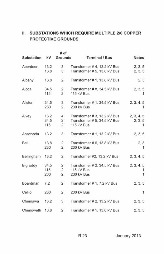
II. SUBSTATIONS WHICH REQUIRE MULTIPLE 2/0 COPPER PROTECTIVE GROUNDS
# ofSubstation kV Grounds Terminal / Bus Notes
Aberdeen 13.2 3 Transformer # 4, 13.2 kV Bus 2, 3, 5 13.8 3 Transformer # 5, 13.8 kV Bus 2, 3, 5
Albany 13.8 2 Transformer # 1, 13.8 kV Bus 2, 3
Alcoa 34.5 2 Transformer # 8, 34.5 kV Bus 2, 3, 5 115 2 115 kV Bus 1
Allston 34.5 3 Transformer # 1, 34.5 kV Bus 2, 3, 4, 5 230 2 230 kV Bus 1
Alvey 13.2 4 Transformer # 3, 13.2 kV Bus 2, 3, 4, 5 34.5 2 Transformer # 5, 34.5 kV Bus 2, 3, 5 115 2 115 kV Bus 1
Anaconda 13.2 3 Transformer # 1, 13.2 kV Bus 2, 3, 5
Bell 13.8 2 Transformer # 6, 13.8 kV Bus 2, 3 230 2 230 kV Bus 1
Bellingham 13.2 2 Transformer #2, 13.2 kV Bus 2, 3, 4, 5
Big Eddy 34.5 2 Transformer # 2, 34.5 kV Bus 2, 3, 4, 5 115 2 115 kV Bus 1 230 2 230 kV Bus 1
Boardman 7.2 2 Transformer # 1, 7.2 kV Bus 2, 3, 5
Celilo 230 2 230 kV Bus 1
Chemawa 13.2 3 Transformer # 2, 13.2 kV Bus 2, 3, 5
Chenoweth 13.8 2 Transformer # 1, 13.8 kV Bus 2, 3, 5
R 24 January 2013
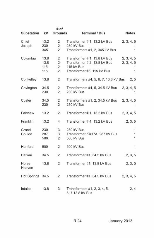
# ofSubstation kV Grounds Terminal / Bus Notes
Chief 13.2 2 Transformer # 1, 13.2 kV Bus 2, 3, 4, 5Joseph 230 2 230 kV Bus 1 345 2 Transformers #1, 2, 345 kV Bus 1
Columbia 13.8 2 Transformer # 1, 13.8 kV Bus 2, 3, 4, 5 13.8 2 Transformer # 2, 13.8 kV Bus 2, 3, 4, 5 115 2 115 kV Bus 1 115 2 Transformer #3, 115 kV Bus 1
Conkelley 13.8 2 Transformers #4, 5, 6, 7, 13.8 kV Bus 2, 5
Covington 34.5 2 Transformers #4, 5, 34.5 kV Bus 2, 3, 4, 5 230 2 230 kV Bus 1
Custer 34.5 2 Transformers #1, 2, 34.5 kV Bus 2, 3, 4, 5 230 2 230 kV Bus 1
Fairview 13.2 2 Transformer # 1, 13.2 kV Bus 2, 3, 4, 5
Franklin 13.2 4 Transformer # 4, 13.2 kV Bus 2, 3, 5
Grand 230 3 230 kV Bus 1Coulee 287 3 Transformer KX17A, 287 kV Bus 1 500 2 500 kV Bus 1
Hanford 500 2 500 kV Bus 1
Hatwai 34.5 2 Transformer #1, 34.5 kV Bus 2, 3, 5
Horse 13.8 2 Transformer #1, 13.8 kV Bus 2, 3, 5Heaven
Hot Springs 34.5 2 Transformer #1, 34.5 kV Bus 2, 3, 4, 5
Intalco 13.8 3 Transformers #1, 2, 3, 4, 5, 2, 4 6, 7 13.8 kV Bus
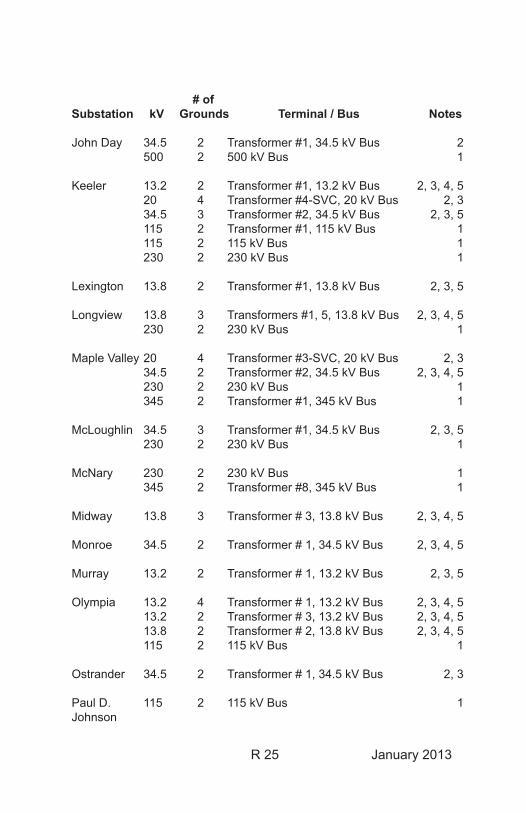
R 25 January 2013
# ofSubstation kV Grounds Terminal / Bus Notes
John Day 34.5 2 Transformer #1, 34.5 kV Bus 2 500 2 500 kV Bus 1
Keeler 13.2 2 Transformer #1, 13.2 kV Bus 2, 3, 4, 5 20 4 Transformer #4-SVC, 20 kV Bus 2, 3 34.5 3 Transformer #2, 34.5 kV Bus 2, 3, 5 115 2 Transformer #1, 115 kV Bus 1 115 2 115 kV Bus 1 230 2 230 kV Bus 1
Lexington 13.8 2 Transformer #1, 13.8 kV Bus 2, 3, 5
Longview 13.8 3 Transformers #1, 5, 13.8 kV Bus 2, 3, 4, 5 230 2 230 kV Bus 1
Maple Valley 20 4 Transformer #3-SVC, 20 kV Bus 2, 3 34.5 2 Transformer #2, 34.5 kV Bus 2, 3, 4, 5 230 2 230 kV Bus 1 345 2 Transformer #1, 345 kV Bus 1
McLoughlin 34.5 3 Transformer #1, 34.5 kV Bus 2, 3, 5 230 2 230 kV Bus 1
McNary 230 2 230 kV Bus 1 345 2 Transformer #8, 345 kV Bus 1
Midway 13.8 3 Transformer # 3, 13.8 kV Bus 2, 3, 4, 5
Monroe 34.5 2 Transformer # 1, 34.5 kV Bus 2, 3, 4, 5
Murray 13.2 2 Transformer # 1, 13.2 kV Bus 2, 3, 5
Olympia 13.2 4 Transformer # 1, 13.2 kV Bus 2, 3, 4, 5 13.2 2 Transformer # 3, 13.2 kV Bus 2, 3, 4, 5 13.8 2 Transformer # 2, 13.8 kV Bus 2, 3, 4, 5 115 2 115 kV Bus 1
Ostrander 34.5 2 Transformer # 1, 34.5 kV Bus 2, 3
Paul D. 115 2 115 kV Bus 1Johnson
R 26 January 2013
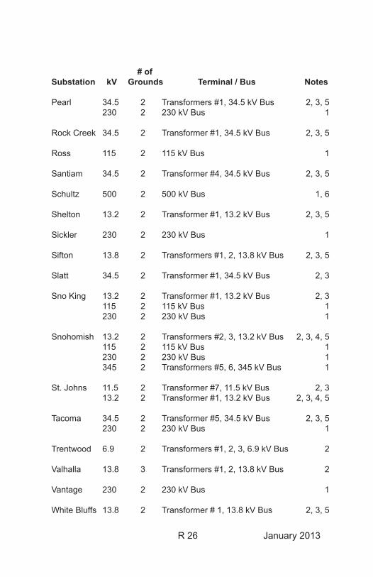
# ofSubstation kV Grounds Terminal / Bus Notes
Pearl 34.5 2 Transformers #1, 34.5 kV Bus 2, 3, 5 230 2 230 kV Bus 1 Rock Creek 34.5 2 Transformer #1, 34.5 kV Bus 2, 3, 5
Ross 115 2 115 kV Bus 1
Santiam 34.5 2 Transformer #4, 34.5 kV Bus 2, 3, 5
Schultz 500 2 500 kV Bus 1, 6
Shelton 13.2 2 Transformer #1, 13.2 kV Bus 2, 3, 5
Sickler 230 2 230 kV Bus 1
Sifton 13.8 2 Transformers #1, 2, 13.8 kV Bus 2, 3, 5
Slatt 34.5 2 Transformer #1, 34.5 kV Bus 2, 3
Sno King 13.2 2 Transformer #1, 13.2 kV Bus 2, 3 115 2 115 kV Bus 1 230 2 230 kV Bus 1
Snohomish 13.2 2 Transformers #2, 3, 13.2 kV Bus 2, 3, 4, 5 115 2 115 kV Bus 1 230 2 230 kV Bus 1 345 2 Transformers #5, 6, 345 kV Bus 1
St. Johns 11.5 2 Transformer #7, 11.5 kV Bus 2, 3 13.2 2 Transformer #1, 13.2 kV Bus 2, 3, 4, 5
Tacoma 34.5 2 Transformer #5, 34.5 kV Bus 2, 3, 5 230 2 230 kV Bus 1
Trentwood 6.9 2 Transformers #1, 2, 3, 6.9 kV Bus 2
Valhalla 13.8 3 Transformers #1, 2, 13.8 kV Bus 2
Vantage 230 2 230 kV Bus 1
White Bluffs 13.8 2 Transformer # 1, 13.8 kV Bus 2, 3, 5
R 27 January 2013
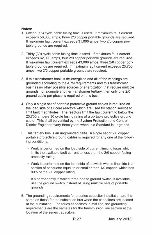
Notes:1. Fifteen (15) cycle cable fusing time is used. If maximum fault current
exceeds 56,000 amps, three 2/0 copper portable grounds are required. If maximum fault current exceeds 31,000 amps, two 2/0 copper por-table grounds are required.
2. Thirty (30) cycle cable fusing time is used. If maximum fault current exceeds 62,000 amps, four 2/0 copper portable grounds are required. If maximum fault current exceeds 43,000 amps, three 2/0 copper por-table grounds are required. If maximum fault current exceeds 23,700 amps, two 2/0 copper portable grounds are required.
3. If this transformer bank is de-energized and all of the windings are grounded according to the APM requirements and this transformer bus has no other possible sources of energization that require multiple grounds, for example another transformer tertiary, then only one 2/0 ground cable per phase is required on this bus.
4. Only a single set of portable protective ground cables is required on the load side of air core reactors which are used for station service to limit fault magnitudes. The reactors limit the fault current to below the 23,700 ampere 30 cycle fusing rating of a portable protective ground cable. This shall be verified by the System Protection and Control District Engineer every three years when this Standard is upgraded.
5. This tertiary bus is an ungrounded delta. A single set of 2/0 copper portable protective ground cables is required for any one of the follow-ing conditions.
• Work is performed on the load side of current limiting fuses which limits the available fault current to less than the 2/0 copper fusing ampacity rating.
• Work is performed on the load side of a switch whose line side is a section of conductor equal to or smaller than 1/0 copper, which has 80% of the 2/0 copper rating.
• If a permanently installed three-phase ground switch is available, use the ground switch instead of using multiple sets of portable grounds.
6. The grounding requirements for a series capacitor installation are the same as those for the substation bus when the capacitors are located at the substation. For series capacitors in mid line, the grounding requirements are the same as for the transmission line section at the location of the series capacitors.
R 28 January 2013
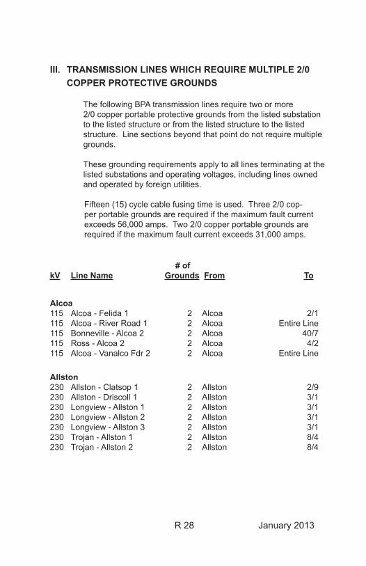
III. TRANSMISSION LINES WHICH REQUIRE MULTIPLE 2/0 COPPER PROTECTIVE GROUNDS
The following BPA transmission lines require two or more 2/0 copper portable protective grounds from the listed substation to the listed structure or from the listed structure to the listed structure. Line sections beyond that point do not require multiple grounds.
These grounding requirements apply to all lines terminating at the listed substations and operating voltages, including lines owned and operated by foreign utilities.
Fifteen (15) cycle cable fusing time is used. Three 2/0 cop-per portable grounds are required if the maximum fault current exceeds 56,000 amps. Two 2/0 copper portable grounds are required if the maximum fault current exceeds 31,000 amps.
# of kV Line Name Grounds From To
Alcoa115 Alcoa - Felida 1 2 Alcoa 2/1115 Alcoa - River Road 1 2 Alcoa Entire Line115 Bonneville - Alcoa 2 2 Alcoa 40/7115 Ross - Alcoa 2 2 Alcoa 4/2115 Alcoa - Vanalco Fdr 2 2 Alcoa Entire Line
Allston230 Allston - Clatsop 1 2 Allston 2/9230 Allston - Driscoll 1 2 Allston 3/1230 Longview - Allston 1 2 Allston 3/1230 Longview - Allston 2 2 Allston 3/1230 Longview - Allston 3 2 Allston 3/1230 Trojan - Allston 1 2 Allston 8/4230 Trojan - Allston 2 2 Allston 8/4
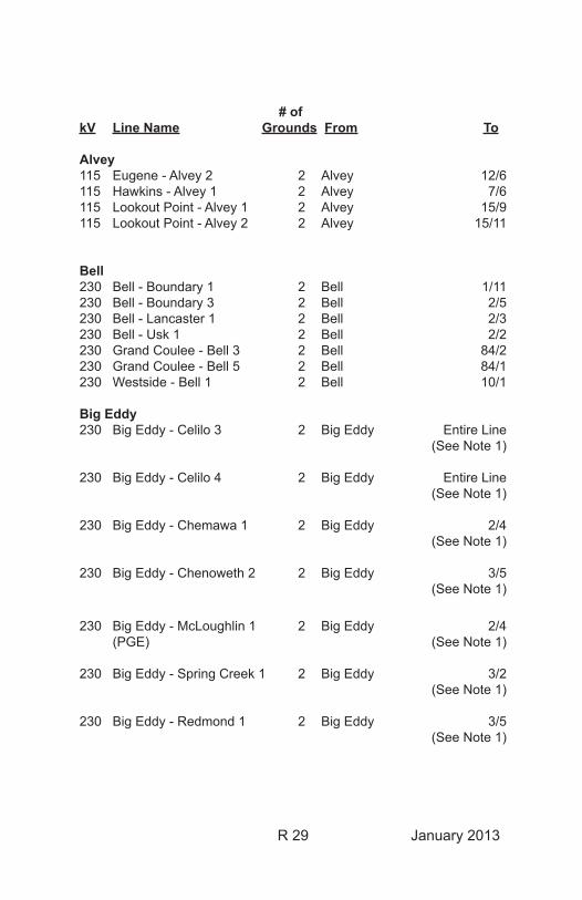
R 29 January 2013
# of kV Line Name Grounds From To
Alvey115 Eugene - Alvey 2 2 Alvey 12/6115 Hawkins - Alvey 1 2 Alvey 7/6115 Lookout Point - Alvey 1 2 Alvey 15/9115 Lookout Point - Alvey 2 2 Alvey 15/11
Bell230 Bell - Boundary 1 2 Bell 1/11230 Bell - Boundary 3 2 Bell 2/5230 Bell - Lancaster 1 2 Bell 2/3230 Bell - Usk 1 2 Bell 2/2230 Grand Coulee - Bell 3 2 Bell 84/2230 Grand Coulee - Bell 5 2 Bell 84/1230 Westside - Bell 1 2 Bell 10/1
Big Eddy230 Big Eddy - Celilo 3 2 Big Eddy Entire Line (See Note 1)
230 Big Eddy - Celilo 4 2 Big Eddy Entire Line (See Note 1)
230 Big Eddy - Chemawa 1 2 Big Eddy 2/4 (See Note 1)
230 Big Eddy - Chenoweth 2 2 Big Eddy 3/5 (See Note 1)
230 Big Eddy - McLoughlin 1 2 Big Eddy 2/4 (PGE) (See Note 1)
230 Big Eddy - Spring Creek 1 2 Big Eddy 3/2 (See Note 1)
230 Big Eddy - Redmond 1 2 Big Eddy 3/5 (See Note 1)
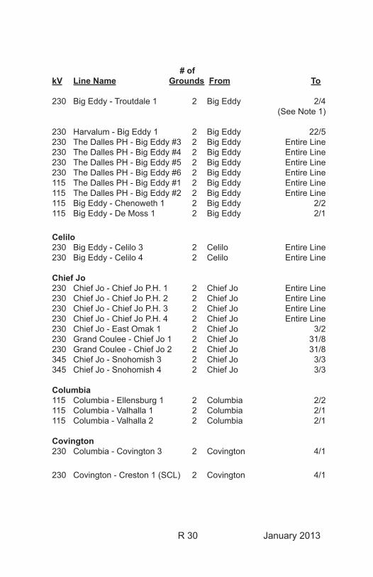
R 30 January 2013
# of kV Line Name Grounds From To
230 Big Eddy - Troutdale 1 2 Big Eddy 2/4 (See Note 1)
230 Harvalum - Big Eddy 1 2 Big Eddy 22/5230 The Dalles PH - Big Eddy #3 2 Big Eddy Entire Line230 The Dalles PH - Big Eddy #4 2 Big Eddy Entire Line230 The Dalles PH - Big Eddy #5 2 Big Eddy Entire Line230 The Dalles PH - Big Eddy #6 2 Big Eddy Entire Line115 The Dalles PH - Big Eddy #1 2 Big Eddy Entire Line115 The Dalles PH - Big Eddy #2 2 Big Eddy Entire Line115 Big Eddy - Chenoweth 1 2 Big Eddy 2/2115 Big Eddy - De Moss 1 2 Big Eddy 2/1
Celilo230 Big Eddy - Celilo 3 2 Celilo Entire Line230 Big Eddy - Celilo 4 2 Celilo Entire Line
Chief Jo230 Chief Jo - Chief Jo P.H. 1 2 Chief Jo Entire Line230 Chief Jo - Chief Jo P.H. 2 2 Chief Jo Entire Line230 Chief Jo - Chief Jo P.H. 3 2 Chief Jo Entire Line230 Chief Jo - Chief Jo P.H. 4 2 Chief Jo Entire Line230 Chief Jo - East Omak 1 2 Chief Jo 3/2230 Grand Coulee - Chief Jo 1 2 Chief Jo 31/8230 Grand Coulee - Chief Jo 2 2 Chief Jo 31/8345 Chief Jo - Snohomish 3 2 Chief Jo 3/3345 Chief Jo - Snohomish 4 2 Chief Jo 3/3
Columbia115 Columbia - Ellensburg 1 2 Columbia 2/2115 Columbia - Valhalla 1 2 Columbia 2/1115 Columbia - Valhalla 2 2 Columbia 2/1
Covington230 Columbia - Covington 3 2 Covington 4/1
230 Covington - Creston 1 (SCL) 2 Covington 4/1
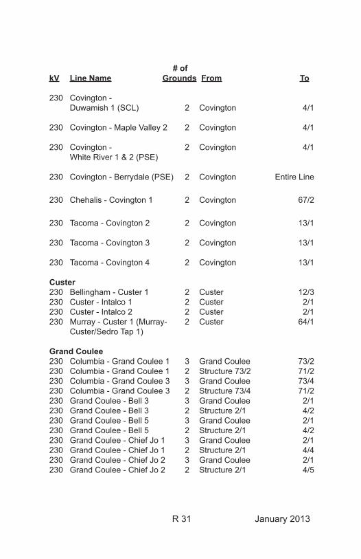
R 31 January 2013
# of kV Line Name Grounds From To
230 Covington - Duwamish 1 (SCL) 2 Covington 4/1
230 Covington - Maple Valley 2 2 Covington 4/1
230 Covington - 2 Covington 4/1 White River 1 & 2 (PSE)
230 Covington - Berrydale (PSE) 2 Covington Entire Line
230 Chehalis - Covington 1 2 Covington 67/2
230 Tacoma - Covington 2 2 Covington 13/1
230 Tacoma - Covington 3 2 Covington 13/1
230 Tacoma - Covington 4 2 Covington 13/1
Custer230 Bellingham - Custer 1 2 Custer 12/3230 Custer - Intalco 1 2 Custer 2/1230 Custer - Intalco 2 2 Custer 2/1230 Murray - Custer 1 (Murray- 2 Custer 64/1 Custer/Sedro Tap 1)
Grand Coulee230 Columbia - Grand Coulee 1 3 Grand Coulee 73/2230 Columbia - Grand Coulee 1 2 Structure 73/2 71/2230 Columbia - Grand Coulee 3 3 Grand Coulee 73/4230 Columbia - Grand Coulee 3 2 Structure 73/4 71/2230 Grand Coulee - Bell 3 3 Grand Coulee 2/1230 Grand Coulee - Bell 3 2 Structure 2/1 4/2230 Grand Coulee - Bell 5 3 Grand Coulee 2/1230 Grand Coulee - Bell 5 2 Structure 2/1 4/2230 Grand Coulee - Chief Jo 1 3 Grand Coulee 2/1230 Grand Coulee - Chief Jo 1 2 Structure 2/1 4/4230 Grand Coulee - Chief Jo 2 3 Grand Coulee 2/1230 Grand Coulee - Chief Jo 2 2 Structure 2/1 4/5
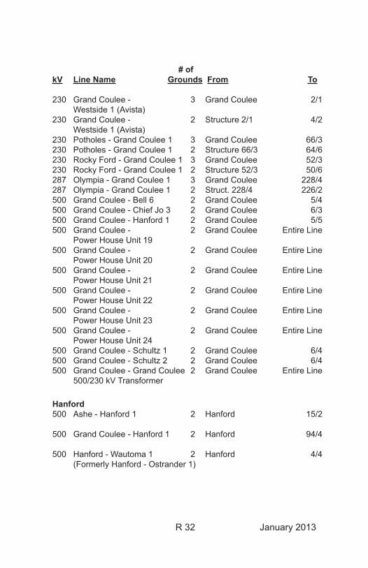
R 32 January 2013
# of kV Line Name Grounds From To
230 Grand Coulee - 3 Grand Coulee 2/1 Westside 1 (Avista)230 Grand Coulee - 2 Structure 2/1 4/2 Westside 1 (Avista)230 Potholes - Grand Coulee 1 3 Grand Coulee 66/3230 Potholes - Grand Coulee 1 2 Structure 66/3 64/6230 Rocky Ford - Grand Coulee 1 3 Grand Coulee 52/3230 Rocky Ford - Grand Coulee 1 2 Structure 52/3 50/6287 Olympia - Grand Coulee 1 3 Grand Coulee 228/4287 Olympia - Grand Coulee 1 2 Struct. 228/4 226/2500 Grand Coulee - Bell 6 2 Grand Coulee 5/4500 Grand Coulee - Chief Jo 3 2 Grand Coulee 6/3500 Grand Coulee - Hanford 1 2 Grand Coulee 5/5500 Grand Coulee - 2 Grand Coulee Entire Line Power House Unit 19500 Grand Coulee - 2 Grand Coulee Entire Line Power House Unit 20500 Grand Coulee - 2 Grand Coulee Entire Line Power House Unit 21500 Grand Coulee - 2 Grand Coulee Entire Line Power House Unit 22500 Grand Coulee - 2 Grand Coulee Entire Line Power House Unit 23500 Grand Coulee - 2 Grand Coulee Entire Line Power House Unit 24500 Grand Coulee - Schultz 1 2 Grand Coulee 6/4500 Grand Coulee - Schultz 2 2 Grand Coulee 6/4500 Grand Coulee - Grand Coulee 2 Grand Coulee Entire Line 500/230 kV Transformer
Hanford500 Ashe - Hanford 1 2 Hanford 15/2 500 Grand Coulee - Hanford 1 2 Hanford 94/4
500 Hanford - Wautoma 1 2 Hanford 4/4 (Formerly Hanford - Ostrander 1)

R 33 January 2013
# of kV Line Name Grounds From To 500 Hanford - Wautoma 2 2 Hanford 4/4 (Formerly Hanford - John Day 1)
500 Lower Monumental - 2 Hanford 51/4 Hanford 1 500 Vantage - Hanford 1 2 Hanford 22/2
John Day500 John Day - Big Eddy 1 2 John Day 5/4500 John Day - Big Eddy 2 2 John Day 5/4500 John Day - Grizzly 1 2 John Day 5/6500 John Day - Grizzly 2 2 John Day 5/6500 John Day - Marion 1 2 John Day 5/4
500 Rock Creek - John Day 1 2 John Day 10/1 (Formerly John Day - Rock Creek 1)
500 John Day Power House - 2 John Day Entire Line John Day 1
500 John Day Power House - 2 John Day Entire Line John Day 2
500 John Day Power House - 2 John Day Entire Line John Day 3
500 John Day Power House - 2 John Day Entire Line John Day 4
500 Slatt - John Day 1 2 John Day 26/3
500 Slatt - John Day 2 2 John Day 73/5
Keeler115 Keeler - 230 kV Transformer 1 2 Keeler Entire Line115 Keeler - 230 kV Transformer 3 2 Keeler Entire Line115 Keeler - Forest Grove 2 2 Keeler 2/2115 Keeler - Oregon City 2 2 Keeler 2/1115 Keeler - Tillamook 1 2 Keeler 2/2115 St. Johns - Keeler 2 2 Keeler 9/8230 Rivergate - Keeler 1 2 Keeler 8/3
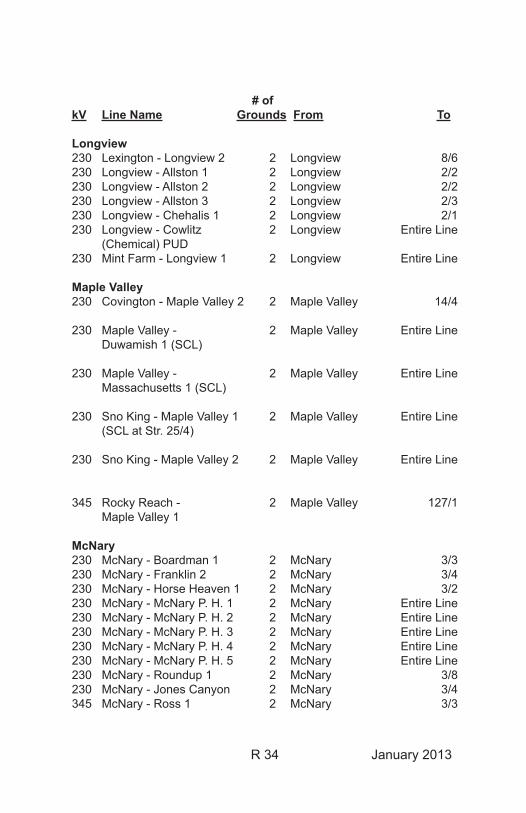
R 34 January 2013
# of kV Line Name Grounds From To
Longview230 Lexington - Longview 2 2 Longview 8/6230 Longview - Allston 1 2 Longview 2/2230 Longview - Allston 2 2 Longview 2/2230 Longview - Allston 3 2 Longview 2/3230 Longview - Chehalis 1 2 Longview 2/1230 Longview - Cowlitz 2 Longview Entire Line (Chemical) PUD230 Mint Farm - Longview 1 2 Longview Entire Line
Maple Valley230 Covington - Maple Valley 2 2 Maple Valley 14/4
230 Maple Valley - 2 Maple Valley Entire Line Duwamish 1 (SCL)
230 Maple Valley - 2 Maple Valley Entire Line Massachusetts 1 (SCL)
230 Sno King - Maple Valley 1 2 Maple Valley Entire Line (SCL at Str. 25/4)
230 Sno King - Maple Valley 2 2 Maple Valley Entire Line
345 Rocky Reach - 2 Maple Valley 127/1 Maple Valley 1
McNary230 McNary - Boardman 1 2 McNary 3/3230 McNary - Franklin 2 2 McNary 3/4230 McNary - Horse Heaven 1 2 McNary 3/2230 McNary - McNary P. H. 1 2 McNary Entire Line230 McNary - McNary P. H. 2 2 McNary Entire Line230 McNary - McNary P. H. 3 2 McNary Entire Line230 McNary - McNary P. H. 4 2 McNary Entire Line230 McNary - McNary P. H. 5 2 McNary Entire Line230 McNary - Roundup 1 2 McNary 3/8230 McNary - Jones Canyon 2 McNary 3/4345 McNary - Ross 1 2 McNary 3/3
R 35 January 2013
# of kV Line Name Grounds From To
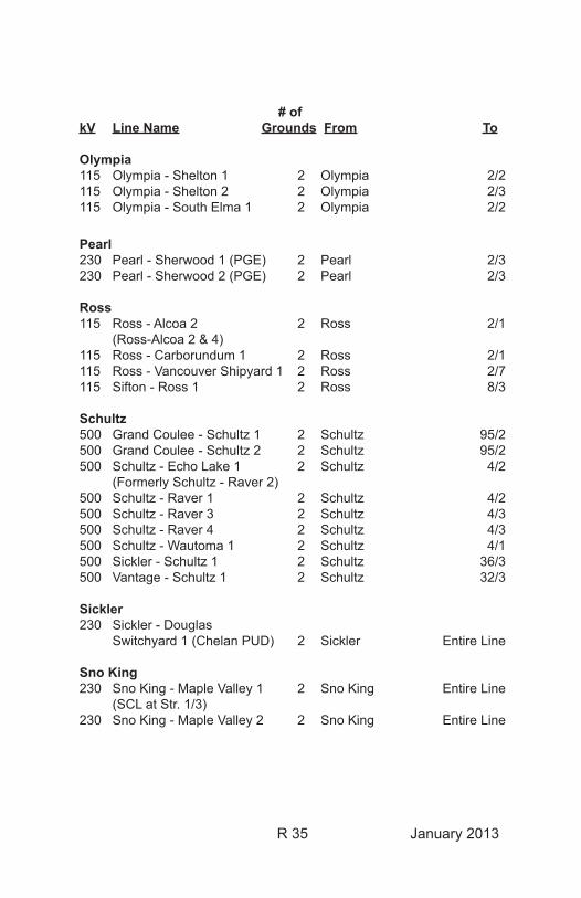
Olympia115 Olympia - Shelton 1 2 Olympia 2/2115 Olympia - Shelton 2 2 Olympia 2/3115 Olympia - South Elma 1 2 Olympia 2/2
Pearl230 Pearl - Sherwood 1 (PGE) 2 Pearl 2/3230 Pearl - Sherwood 2 (PGE) 2 Pearl 2/3
Ross115 Ross - Alcoa 2 2 Ross 2/1 (Ross-Alcoa 2 & 4)115 Ross - Carborundum 1 2 Ross 2/1115 Ross - Vancouver Shipyard 1 2 Ross 2/7115 Sifton - Ross 1 2 Ross 8/3
Schultz500 Grand Coulee - Schultz 1 2 Schultz 95/2500 Grand Coulee - Schultz 2 2 Schultz 95/2500 Schultz - Echo Lake 1 2 Schultz 4/2 (Formerly Schultz - Raver 2)500 Schultz - Raver 1 2 Schultz 4/2500 Schultz - Raver 3 2 Schultz 4/3500 Schultz - Raver 4 2 Schultz 4/3500 Schultz - Wautoma 1 2 Schultz 4/1500 Sickler - Schultz 1 2 Schultz 36/3500 Vantage - Schultz 1 2 Schultz 32/3
Sickler230 Sickler - Douglas Switchyard 1 (Chelan PUD) 2 Sickler Entire Line
Sno King230 Sno King - Maple Valley 1 2 Sno King Entire Line (SCL at Str. 1/3)230 Sno King - Maple Valley 2 2 Sno King Entire Line
R 36 January 2013
# of kV Line Name Grounds From To
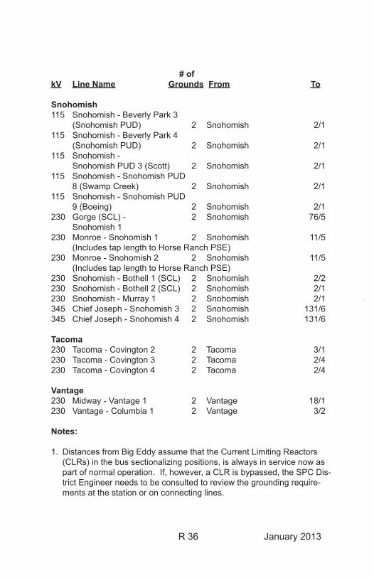
Snohomish115 Snohomish - Beverly Park 3 (Snohomish PUD) 2 Snohomish 2/1115 Snohomish - Beverly Park 4 (Snohomish PUD) 2 Snohomish 2/1115 Snohomish - Snohomish PUD 3 (Scott) 2 Snohomish 2/1115 Snohomish - Snohomish PUD 8 (Swamp Creek) 2 Snohomish 2/1115 Snohomish - Snohomish PUD 9 (Boeing) 2 Snohomish 2/1230 Gorge (SCL) - 2 Snohomish 76/5 Snohomish 1230 Monroe - Snohomish 1 2 Snohomish 11/5 (Includes tap length to Horse Ranch PSE)230 Monroe - Snohomish 2 2 Snohomish 11/5 (Includes tap length to Horse Ranch PSE)230 Snohomish - Bothell 1 (SCL) 2 Snohomish 2/2230 Snohomish - Bothell 2 (SCL) 2 Snohomish 2/1230 Snohomish - Murray 1 2 Snohomish 2/1345 Chief Joseph - Snohomish 3 2 Snohomish 131/6345 Chief Joseph - Snohomish 4 2 Snohomish 131/6
Tacoma230 Tacoma - Covington 2 2 Tacoma 3/1230 Tacoma - Covington 3 2 Tacoma 2/4230 Tacoma - Covington 4 2 Tacoma 2/4
Vantage230 Midway - Vantage 1 2 Vantage 18/1230 Vantage - Columbia 1 2 Vantage 3/2
Notes:
1. Distances from Big Eddy assume that the Current Limiting Reactors (CLRs) in the bus sectionalizing positions, is always in service now as part of normal operation. If, however, a CLR is bypassed, the SPC Dis-trict Engineer needs to be consulted to review the grounding require-ments at the station or on connecting lines.
R 37 January 2013
G-7 GROUNDS, PORTABLE PROTECTIVE, CAPACITORS
The internal resistor of a capacitor cell shall not be depended upon to discharge capacitors. A bayonet-type short circuiting and grounding rod shall be applied, for at least 5 seconds, between all insulated terminals and the capacitor case before handling. Cells removed or stored shall be shorted between all insulated terminals and the capacitor case with at least a No. 18 AWG wire.
SERIES CAPACITORSSeries capacitor installations shall be protected by three-phase grounding on both sides, and on the insulated platform of the phase or phases being worked on.
Permanently installed ground switches may be used in lieu of portable grounds to short the phases.
Portable protective grounds are not required between phases to accomplish the visible three-phase short. The three-phase short may be accomplished through above-ground metallic structural interconnections between phases. Operating linkage or metallic interconnections with moving or rotating parts cannot be used to make the three-phase short.
If there are no above-ground metallic structural interconnections between phases, the three-phase short may be accomplished using the existing ground mat. Before the ground mat may be used to effect the three-phase short, the continuity of the ground mat must first have been confirmed by the testing method detailed in Substation Maintenance Standards & Guides SM-STD-13-1-14, Grounding Grid Riser Test Procedure.
SHUNT CAPACITORSShunt capacitor installations shall be grounded on both the line and neutral sides. The neutral side shall be grounded either by installing a portable protective ground or by means of a permanently installed ground connection.
Permanently installed ground switches may be used in lieu of portable grounds to short the phases.
R 38 January 2013
Portable protective grounds are not required between phases to accomplish the visible three-phase short provided the ground switch structure has above ground metallic structural interconnections between phases. Operating linkage or metallic interconnections with moving or rotating parts cannot be used to make the three-phase short.
If there are no above-ground metallic structural interconnections between phases, temporary above-ground metallic connections are to be made between the ground switch structures.
G-8 GROUNDING, PORTABLE PROTECTIVE, SHUNT REACTORS AND TRANSFORMERS
Shunt reactor and transformer installations shall be grounded on both the line and neutral sides. The neutral side shall be grounded by either installing a portable protective ground or by means of a permanently installed ground connection.
G-9 GROUNDS, PORTABLE PROTECTIVE, STATIC WIREBefore touching or coming within the Minimum Approach Distance of overhead static (ground) wire, unless an approved barrier is in place (see Rule B-1) or the worker is insulated from any other exposed conductive object while conducting live-line bare-hand work, it must be grounded at that location by either a portable protective ground or a permanent ground connection. Except: At 500 kV or above a portable protective ground must be installed. Some permanent overhead ground wire connections and/or conductors are subject to corrosion and vibration problems, resulting in a loss of conductivity. This is especially true on 500 kV.
This conductor is subject to accidental energization from the same sources described in Rule G-1.

R 39 January 2013
G-10 GROUNDING OF EQUIPMENT, TOOLS, AND METALLIC CABLES
Power/Lift Equipment:When a vehicle is parked near energized high-voltage equipment, there can be a risk of electric shock if contact is made between the vehicle and a grounded object. This is due to the capacitive charge that can build up on the vehicle. [Reference Substation Maintenance Standard and Guide, SM-STD-13-1-15, Grounding Work Equipment and Vehicles in Substations and TLM Standard and Guide I.A.2, Grounding]
If the vehicle is to be bonded to a grounded object to prevent capacitive charge build-up, personnel must avoid getting in series with the discharge circuit.
Manlifts, cranes, and other overhead lift equipment used where the possibility of accidental contact with normally energized high voltage parts exist, shall be connected to the substation ground mat within energized switchyards or to a ground rod in other locations with a 2/0 copper ground lead. Multiple ground leads, attached to separate ground rods or mat connections, shall be utilized on equipment in the same number that would be required for grounding the circuit(s).
Ground mat connected equipment:If the possibility of contact with normally energized high voltage parts does not exist, power/lift equipment shall be grounded with a single 2/0 copper ground or static ground in accordance with Substation Maintenance Standard and Guide, XIII.A.15, Grounding Work Equipment and Vehicles in Substations and TLM Work Standard I.A, Grounding.
R 40 January 2013
Non Groundmat connected equipment:Vehicle/equipment grounding is not required when all three of the following conditions are met, in accordance with TLM Standard and Guide I.A.2, Grounding:
The equipment is located and positioned in such a manner that: 1. Equipment or any conductive part of it cannot violate the MAD of any nearby energized conductor, and 2. The equipment or any conductive part of it will not make contact with a de-energized and properly grounded conductor, and 3. A person cannot make simultaneous contact between the equipment and any conductive object that is remote to or not at the potential of the grounding system at the worksite.NOTE: A derrick shall be grounded while driving anchor rods or augering.
Extension Cords, Tools, Metallic Cables:When an extension cord is used in an energized switchyard, the cord’s grounding box must be clamped to a solidly grounded fixture before the extension cord is connected to a switchyard receptacle. If a solidly grounded fixture is not available within 10 feet of the worksite, the grounding box shall be attached to a ground rod. When using double-insulated tools, work may be done within 25 feet of the grounding box.
Extension cords or other metallic cable (i.e., telephone or temporary power) used in a switchyard should not be laid parallel to high voltage bus or overhead circuits due to the possibility of high induced voltages. These cables shall not be extended to locations off the substation ground mat unless a properly designed and installed ground mat extension or isolation is used.
Ground Grid ConductorsBefore cutting any ground grid conductor, shunt the conductor with a 2/0 portable protective ground. When splicing a ground grid conductor, jumper around the splice with a 2/0 portable protective ground applied by live-line tools.
R 41 January 2013
G-11 GROUNDS, PORTABLE PROTECTIVE, FIBER OPTICSBefore touching or coming within the Minimum Approach Distance of a fiber optical ground wire (OPGW), it must be grounded at that location by either a portable protective ground or a permanent ground connection. Exception: At 500 kV or above, a portable protective ground must be used. [Reference BPA Work Standard BPA-WS-9-3, Fiber Optics]
G-12 GROUNDS, 1/0 URD GROUNDSUnderground residential distribution (URD) grounds may be used as an alternative to grounding URD or Pad-Mount equipment for personal protection against electric shock. The use of URD grounds is only permissible where the available fault current on the circuit to be grounded does not exceed 5800 Amps for 30 cycles. Refer to BPA Work Standard X.L., Work on Underground Residential Distribution (URD) Station Service 25 kV and Below for a listing of locations where 1/0 URD grounds are approved for use and the procedures for determining ground fault current.
URD grounds consist of an insulated connector (elbow), copper ground conductor, and ground clamp and shall have a minimum rating of 1/0. URD grounds may have multiple 1/0 ground conductors or conductors rated 2/0 but the elbow is limited to 1/0 and the ground shall not be used for any application above the 1/0 fault current limit.
The use of URD grounds requires the appropriate insulated tools, accessories, and personal protective clothing as listed in the Work Standards for X.L., Work on Underground Residential Distribution (URD) Station Service 25 kV and Below and X.J., Arc-Flash Personal Protective Equipment for Work on Energized AC and DC Circuits.
R 42 January 2013
H-1 HEAD PROTECTION
Where Required:Hard hats approved by the Administration shall be worn by ALL PERSONS in the following locations and conditions except for work inside transformers, power circuit breakers, under vehicles, or in similar restricted/protected situations:
1. In fenced substation yards and other designated hard hat areas.
2. When engaged in or when in the close proximity of outdoor work or in all areas where there is exposure above head level to moving equipment, work, or material handling.
Identification/Color-Coding System:To distinguish between Qualified Electrical Employees and others, YELLOW hard hats will be restricted to holders of Electrical Worker Permits.
Additional hard hat colors utilized on the BPA system are:
BLUE: Riggers RED: Construction Equipment Operators GRAY: Carpenters WHITE: All Others * Other colors utilized are listed in Chapter Two, H-1
R 43 January 2013
H-2 HEARING PROTECTIONHearing protection shall be worn by employees exposed to elevated noise levels (i.e., chainsaws, brush chippers, jackhammers, etc.).
Hearing protection is required when sound levels exceed those shown in the table below:
Duration per day in hours dBA 8 hours 85 4 hours 90 2 hours 95 1 hour 100 1/2 hour 105 1/4 hour 110
Additional hearing conservation criteria is contained in the Safety and Health Program Handbook.
I-1 IDENTIFICATION OF CIRCUITSNo work shall be performed on any circuit until positive identification of all electrical circuits in the work area has been established.
J-1 JOB BRIEFINGThe person-in-charge of the job shall conduct job briefings with all workers assigned to the job. Job briefings shall be held at the work site with ad-ditional briefings conducted when work situations change that may pose different or additional hazards to workers. Employees working alone shall ensure that their day’s work is planned and performed as if a briefing was conducted. When more than one craft are working together, the person-in-charge of the job must be clearly established as part of the job briefing.
All job briefings must cover at least the following subjects:
• Hazards associated with the job • Work procedures • Special precautions • Energy source controls • Personal protective equipment • Clearances, Work Permits, Hold Orders
R 44 January 2013
L-1 LADDERS, SECURING OFLadders must be adequately secured at all times.
Extension ladders shall be of sufficient length to extend 3 ft above the working level if departure from it may occur.
Step ladders shall be used in the fully open and locked position. The top shall not be used as a step.
L-2 LOW VOLTAGE CIRCUIT, WORK ONCircuits energized from 50 volts to 600 volts are classified as low voltage. Low voltage circuits do not include testing with portable test equipment. When work is to be performed on or near low voltage circuits, employees shall either:
1. De-energize the circuit, or
2. Use approved protective equipment, (i.e. rubber gloves, insulated barriers, or insulated tools) as required to prevent body contact with energized parts and use fire resistant personal protective equipment as per BPA Work Standard BPA-WS-11-6, Arc Flash Personal Protective Equipment for work on Low Voltage AC and DC Circuits.
R 45 January 2013
L-3 LOCKOUT/TAGOUTThis Lockout/Tagout rule applies to work involving circuits, equipment or energy storage systems in which the unexpected startup or release of stored energy could cause injury. The Lockout/Tagout system requires individual locks and a specific Equipment Lockout Do Not Operate Tag for each Authorized Employee involved in work on any circuit, piece of equipment or energy storage system.
Authorized Employee: An employee who locks out or tags out a circuit, piece of equipment or energy storage system in order to work on that circuit, piece of equipment or energy storage system. An employee is considered an authorized employee as long as they are performing an ele-ment of the work that is covered by the energy control procedure.
When work is performed by a crew, a Group Lockout/Tagout procedure shall be implemented. Group Lockout/Tagout requires each authorized employee to affix an Equipment Lockout Do Not Operate Tag and a personal Lockout/Tagout lock on the group Lockout/Tagout device before beginning work and to remove it when they complete the work. One authorized employee shall be designated as having primary responsibil-ity for all authorized employees working under the protection of Group Lockout/Tagout. The Authorized Employee is responsible for following the procedures and responsibilities of Operating Bulletin No. 2 VIII., Low Voltage Circuits/Equipment and Energy Storage Systems and BPA Work Standard and Guide BPA-WS-8-1, Lockout/Tagout.
If the Authorized Employee who applied the Lockout/Tagout device is not available to release it, the employee’s immediate supervisor may remove it provided the supervisor does the following:
• Verify that the Authorized Employee is not at the facility.
• Notify all affected employees that the Lockout/Tagout device will be removed.
• Make a reasonable effort to contact the Authorized Employee to inform them that their Lockout/Tagout device has been removed.
• Ensure that the Authorized Employee has this knowledge before they resume work.
R 46 January 2013
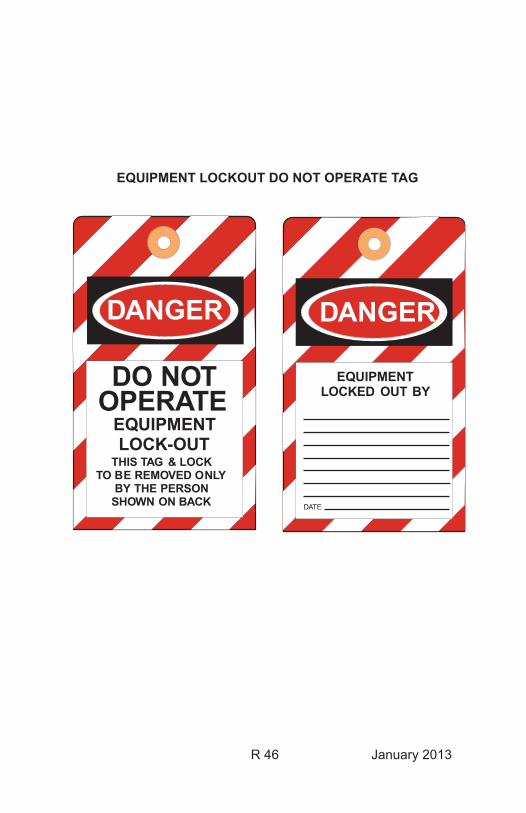
EQUIPMENT LOCKOUT DO NOT OPERATE TAG
DANGER
DO NOTOPERATE
EQUIPMENTLOCK-OUT
THIS TAG & LOCKTO BE REMOVED ONLY
BY THE PERSONSHOWN ON BACK
EQUIPMENTLOCKED OUT BY
DATE
DANGER
R 47 January 2013
M-1 MINIMUM APPROACH DISTANCENo part of a worker’s body or any conductive object held by a worker shall be moved closer to energized high voltage parts than the applicable Minimum Approach Distance unless an approved barrier is in place (see Rule B-1) or the worker is insulated from any other exposed conductive object while conducting live-line bare-hand work under the provisions of the Liveline Manual.
When work is to be performed within the Minimum Approach Distance, including the installation and removal of barriers, one of the following must be employed:
1. Clearance2. Live-line tools (including dielectric gloves up to 5 kV)3. Approved barriers4. Approved bare-hand work procedures (limited to work on
transmission lines normally operated at 230 kV and higher voltages)
Conductive objects, such as insulator support hardware, which extend into Minimum Approach Distances, may be contacted outside the applicable Minimum Approach Distance. However, such objects must have been installed in accordance with approved design standards and be fixed or limited in movement so that the designed clearances cannot be reduced.
Only persons qualified and trained to perform work safely on or in close proximity to energized lines and equipment shall be allowed to work or operate equipment up to the applicable Minimum Approach Distance in the following table. Unqualified persons shall not enter within 15 feet on circuits up to 345 kV and 20 feet on circuits greater than 345 kV unless escorted as permitted in the Rules of Conduct Handbook. This table applies only to qualified persons and provides Minimum Approach Distances in inches for phase-to-phase voltages commonly used on the BPA system. The MAD table is based on the maximum transient voltages that can be generated by automatic switching on the BPA system. These distances are the minimum required by the Occupational Safety and Health Administration (OSHA) and the National Electrical Safety Code (NESC).
A Safety Watcher is required anytime mechanical equipment is working closer than 15’ on circuits up to 345 kV or 20’ on 500 kV circuits. The Safety Watcher shall ensure that these qualified persons or equipment operated by qualified persons shall not come closer than the applicable MAD in this table.
R 48 January 2013
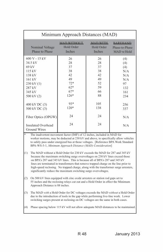
Minimum Approach Distances (MAD)
Nominal VoltagePhase to Phase Inches Inches
26 28 37 38 42 49
72* 62* 67*126*
93*120*
24
24
600 V - 15 kV34.5 kV69 kV115 kV138 kV161 kV230 kV (1)287 kV345 kV500 kV (2)
400 kV DC (3)500 kV DC (3)
Fiber Optics (OPGW)
Insulated OverheadGround Wires
26283738424952596688
105138
24
24
MAD WITHHold Order
MAD WITHOUTHold Order
* The inadvertent movement factor (IMF) of 12 inches, included in MAD for worker motions, may be deducted at 230 kV and above, to specifically allow vehicles to safely pass under energized bus at those voltages. [Reference BPA Work Standard BPA-WS-5-1, Minimum Approach Distance (MAD) Consideration]
(1) The MAD without a Hold Order for 230 kV exceeds the MAD for 287 and 345 kV because the maximum switching surge overvoltages on 230 kV lines exceed those on BPA’s 287 and 345 kV lines. This is because all of BPA’s 287 and 345 kV lines are terminated in transformers that remove trapped charge on the line prior to high-speed reclosing. No trapped charge, along with the transformer surge arresters, significantly reduce the maximum switching surge overvoltages.
(2) On 500 kV lines equipped with zinc oxide arresters or station rod gaps set to 55 inches and the reclosing relays cut out and a Hold Order in effect the Minimum Approach Distance is 88 inches.
(3) The MAD with a Hold Order for DC voltages exceeds the MAD without a Hold Order due to the introduction of tools in the gap while performing live-line work. Lower switching surges present at reclosing on DC voltages are the same in both cases.
(4) Phase spacing below 115 kV will not allow adequate MAD distances to be maintained.
(4) (4) (4) N/A N/A N/A 97 132 161 234
256 337
N/A
N/A
Phase-to-PhaseMAD w/Hold
BAREHAND
R 49 January 2013
P-1 POWER EQUIPMENT Before an operator leaves the controls of power equipment, the load, forks, bucket, or blade shall be lowered and all the brakes set. If the equipment is on an incline, the tires shall also be chocked.
An exception may be taken to that part of the rule requiring the “lowering of the load” during conductor stringing, sagging, and pre-stressing operations.
R-1 ROPE, WIRE1. Wire rope inspection
Wire rope shall be inspected each day before being used. Rope having six broken wires in one rope lay shall not be used. Rope which gives the appearance of rough usage, corrosion, excessive kinking or other damage shall not be used.
2. Safety Factor The ratio of breaking (ultimate) strength of rope to the working load limit (WLL) is called the safety factor. The safety factor must be sufficient to ensure a reasonable margin of strength above the working load to account for actual field conditions. The working load limit is determined by dividing the breaking strength by the appropriate safety factor. Use of the proper safety factor is required to prevent failure of the rope due to unpredictable circumstances or impact loads.
a. The safety factor for wire rope in lifting and pulling shall not be less than 5 unless otherwise specified by the equipment manufacturer.
b. The safety factor for wire rope used to lift workers off the ground shall not be less than 8.
3. Wire Rope Eye Splices Only logger eye splices or pressed fittings installed by competent personnel may be used.

R 50 January 2013
R-2 ROPE, SYNTHETICDepending upon the type of material, synthetic rope shall have the following safety factors:
Safety Factor Type of Material Normal Use Lifting People Polyester (Polydacron) 6 10 Polypropylene 6 10 Nylon 9 10HMPE (High-Modulus Polyethylene 6 10 Construction: Plasma, Spectra, Spectron, Ultra Blue)
R-3 RIGGING, EQUIPMENT
SAFETY FACTORSThe ratio of the breaking strength of rigging components to the working load limit (WLL) is called the safety factor. Safety factors of rigging components vary dependant upon manufacturer’s working load limits.
Working load limits of all rigging components, including stringing lines, pulling lines, sock connections and load-bearing hardware and accessories, shall be identified prior to use. The manufacturer’s working load limits (WLL) for rigging components shall not be exceeded. If the WLL of rigging components of factory-supplied equipment cannot be verified, they shall be replaced with approved rigging components.
1. Shackles The shackles used must be at least 1/4 inch larger than the wire rope. Shackles must be stamped with the rated working load limit (WLL).
Note: Approved shackles manufactured prior to 1995 will be marked with safe working load (SWL).
2. Blocks and Sheaves Blocks and sheaves shall be inspected before any lift or pull is made.
3. Winches The operator shall inspect the winch and ensure that all systems are in good operating condition before any lift or pull is made. Adjustments and repairs shall be done by qualified persons.
R 51 January 2013
4. Slings, Wire Rope Wire rope slings shall be inspected for damage or defects each day before being used. Wire rope slings shall have a safety factor of 5 for normal use. When lifting people, use a safety factor of 8. Slings having 5 broken wires in one strand in one rope lay shall not be used. Rope slings, which give the appearance of rough usage, corrosion, excessive kinking or other damage, shall not be used.
5. Slings, Synthetic Manufactured slings shall have a safety factor of 5 for normal use. When lifting people, use a safety factor of 8. Each sling shall bear a tag containing workload limit, capacity for each hitch used, type of material used, sling serial number, and date of manufacture.
Depending upon the type of material, synthetic fibers are subject to degradation and loss of strength due to sunlight and exposure to field conditions. Follow manufacturer’s recommendations for removing synthetic slings from service due to age and/or fiber damage. Synthetic slings shall be thoroughly inspected prior to use as well as an annual inspection for deterioration and sling damage.
R 52 January 2013
R-4 RADIO FREQUENCY EXPOSURE, FOR PERSONAL COMMUNICATION SYSTEMSRadio Frequency (RF) emissions can be harmful to workers exposed at close proximity to high RF levels for an extended period of time. BPA has established a safe working distance of 5 feet from the front (or face) of structure-mounted transmitting antennas. Workers may be closer than the safe working distance for short periods of time, such as while climbing past the rear of an energized transmitting antenna. Workers may remain closer than the safe working distance only if using a personal RF Expo-sure Monitor. If the RF Exposure Monitor signals an alarm, the antenna should be de-energized during the period of worker exposure, and in no case shall the exposure exceed 6 minutes in any 15-minute period while the RF Exposure Monitor signals an alarm.
The 5-foot rule stated here is based on a system-wide average for most PCS/Cellular antennas on BPA structures. For some antennas the safe working distance may be greater than or less than 5 feet. Any antenna that requires a greater safe working distance than 5 feet will have a warn-ing sign posted at its location to indicate the safe working distance. In the absence of a sign, the safe working distance shall be considered to be 5 feet.
Vehicle-mounted transmitting antennas have a safe working distance of 2 feet while transmitting. The exposed metal parts of a vehicle-mounted transmitting antenna should never be touched while transmitting as it will produce a painful burn on bare skin.
[Reference: BPA Work Standard and Guide BPA-WS-11-5, Communication Antennas – RF Exposure]
R 53 January 2013
R-5 RESPONSIBILITIESEMPLOYER RESPONSIBILITYThe Administration shall provide employment free from or protected against recognized hazards that might cause physical harm or death and must comply with Occupational Safety and Health Administration (OSHA), Departmental, and electrical utility industry standards applicable to BPA operations and activities.
SUPERVISOR RESPONSIBILITYSupervisors shall ensure that employees fully understand how to perform their work with safety to themselves and others. They shall impart to each employee the understanding that willful violations of established safety practices and rules will not be tolerated.
Supervisors shall plan and arrange their work in such a manner that each job will be accomplished with the least hazard to employees, other persons, including the public, and to property. They will advise all workers of any unusual hazards involved in their part of the work and of precautions to be observed.
EMPLOYEE RESPONSIBILITYAll workers share with the employer the responsibility for safety. All em-ployees must follow the rules applicable to the job being performed and to report all unsafe tools, unsafe equipment, and hazardous conditions or procedures which come to their attention. Any employee that observes an unsafe procedure or condition has the authority to stop the job and shall immediately notify the employees involved or employee in charge. Willing-ness and ability to work with safety to one’s self and others shall be an ongoing measure of each employee’s performance.
R-6 MOBILE RADIO FREQUENCY ASSIGNMENTStandard radio frequency 172.500 MHz, channel 3, is designated for Transmission Line Maintenance stringing use only. No other mobile radio traffic communication is allowed on this channel un less it is considered an emergency. The assignment of this channel will allow safe communica-tions for employees engaged in line stringing operations.
R 54 January 2013
S-1 SAFETY WATCHER, GENERALA Safety Watcher is an electrical worker who knows and understands the safety rules and the electrical hazards involved in specific work situations. Primarily, Safety Watchers are responsible for limiting the movement of personnel and/or equipment to prevent electrical contact accidents. They have the authority to halt the operation whenever any unsafe act or condition is imminent.
Safety Watchers may be required for either Electrical or Nonelectrical Workers as provided in subsequent paragraphs of this instruction. Only Qualified Electrical Employees or Contract Safety Watchers may be assigned as Safety Watchers for crews working in BPA energized substations or on transmission lines. Except:
Where one lineman and the holder of a Restricted Electrical Worker Permit are working together, the Restricted Electrical Worker may serve as the Safety Watcher for the lineman upon approval of both the lineman and the foreman. It is intended that this exception be used only during occasional climbing inspections, hardware tightening, and other similar situations.
Use of a particular Safety Watcher must be acceptable to all crew members.
A supervisor in charge of a job may not act as a Safety Watcher if there is any possibility of being distracted. Appointment of a Safety Watcher does not relieve a supervisor of the responsibility for the safety of the crew, but it does provide assistance in executing that responsibility. Each employee is responsible for asking for a Safety Watcher whenever one is required. In the event of conflicting judgments, the more conservative interpretation shall prevail pending review and resolution by management.
R 55 January 2013
A Safety Watcher shall take a suitable location and give their undivided attention to ensure that no action on the part of the worker(s) being watched can result in violation of the Minimum Approach Distances as specified in Rule M-1. There must be a definite understanding between the Safety Watcher and the person(s) being watched as to when the watching begins and ends. Safety Watchers, who must leave their assigned jobs, shall first make sure that all worker(s) are in the clear and remain in the clear until the Safety Watcher returns or is replaced. A red or orange vest shall be worn by the assigned Safety Watcher for all work activities which require the continual presence and observation of a Safety Watcher. It may be worn at the discretion of either the person in charge or the assigned Safety Watcher in other situations requiring a Safety Watcher.
The Safety Watcher rule may be waived only when human life is at stake!
S-2 SAFETY WATCHERS FOR QUALIFIED ELECTRICAL EMPLOYEES
A Safety Watcher is required for Qualified Electrical Employees under the following circumstances:
1. When a worker is climbing into, out of, or changing location in a substation structure containing circuits normally energized at 600 volts or more. This does not apply to circuits barricaded or located 15 feet or more from the structure for circuits at 345kV or less and 20 feet or more for circuits operating at greater than 345 kV. Multiple bays shall be considered one structure if workers can pass from one to the other without having to descend to the ground.
2. When inadvertent movement by a worker could result in violating the Minimum Approach Distance as specified in rule M-1.
3. When operating or moving motor-driven equipment in the vicinity of high-voltage circuits and the possibility of accidental contact exists.
4. When performing approved bare-hand procedures.
R 56 January 2013
S-3 SAFETY WATCHERS FOR RESTRICTED ELECTRICAL AND NON-ELECTRICAL WORKERS
The supervisor in charge of any non-electrical work crew has the responsibility of arranging for sufficient Safety Watchers for the protection of all workers involved. Additionally, each Restricted Electrical and Non-Electrical worker is responsible for requesting a Safety Watcher whenever one is required. Restricted Electrical and Non-Electrical workers shall consult with a Qualified Electrical Employee prior to performing work within a substation yard for help in determining if a Safety Watcher is required. A Substation Operator or Electrical Craft Supervisor will make arrangements for the assignment of necessary Safety Watchers.
The supervisor in charge of the nonelectrical work or the individual Restricted Electrical or Non-Electrical worker shall explain to the Safety Watcher the nature and scope of the work to be performed. The Safety Watcher shall establish boundaries for the work to be performed and inform the workers accordingly. These boundaries shall maintain an adequate margin of safety to assure that the Minimum Approach Distance specified in Rule M-1 will not be violated.
Safety Watchers for Restricted Electrical and Non-electrical Workers are required:
1. Whenever a Safety Watcher is required for Qualified Electrical Employees (see S-2 above).
2. Whenever a Clearance is necessary. The Safety Watcher shall obtain such Clearance or verify that the necessary Clearance has been obtained and see that required grounds are installed.
NOTE: Clearances and Safety Watchers are not required for the painting of transmission line towers as long as all painters and all of their rigging remain below the level of the lowest energized conductor and at least 15 feet for circuits at 345kV or less and 20 feet for circuits operating at greater than 345 kV from such conductor. Warning signs or danger flags must be attached at a location consistent with the above, to each tower leg that can be climbed. Painters must be clearly instructed to remain below these signs or markers.
R 57 January 2013
3. When operating or moving motor-driven equipment in energized substation yards which are not guarded or barricaded as provided in Rule B-1.
4. Any time a Qualified Electrical Employee determines that a Safety Watcher is required for any job within a substation yard. If this requirement is not met, the Qualified Electrical Employee shall stop the work.
Safety Watchers for Restricted Electrical and Non-Electrical workers are not required:
1. When the work area is separated from all energized equipment by a guard or barrier approved by the person responsible for the control of entry (see Rule B-1). No change or break in the guard or barrier may be made without the approval of a Qualified Electrical Employee.
2. When heavy equipment operators/truck drivers deliver equipment or materials to designated storage locations within fenced substation yards.
The driver must have a Restricted Electrical Worker Permit or a Non-electrical Worker Permit and have on-site instruction for each storage location from a Qualified Electrical Employee. These storage areas must be isolated or remote from energized facilities so that all work, including access to and from, can be accomplished without any possibility of accidental contact.
3. When workers do not get off the ground without the specific approval of a Qualified Electrical Employee.
4. When a Qualified Electrical Employee determines that the vehicle to be operated has no equipment or loads which would create an unsafe condition if operated within a substation switchyard. In this case there should be a clear understanding as to the route to be taken for travel and limits of movement within the switchyard.
5. When operating a bobcat equipped with a limiting bar in place to limit raising the bucket above cab height, with the approval of a Qualified Electrical Employee.
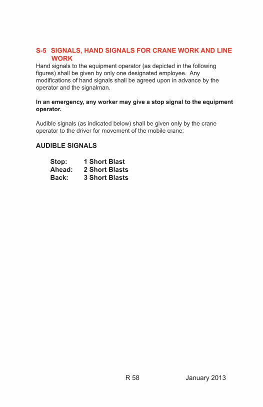
R 58 January 2013
S-5 SIGNALS, HAND SIGNALS FOR CRANE WORK AND LINE WORK
Hand signals to the equipment operator (as depicted in the following figures) shall be given by only one designated employee. Any modifications of hand signals shall be agreed upon in advance by the operator and the signalman.
In an emergency, any worker may give a stop signal to the equipment operator.
Audible signals (as indicated below) shall be given only by the crane operator to the driver for movement of the mobile crane: AUDIBLE SIGNALS
Stop: 1 Short Blast Ahead: 2 Short Blasts Back: 3 Short Blasts
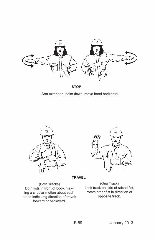
R 59 January 2013
STOP
TRAVEL
Arm extended, palm down, move hand horizontal.
(Both Tracks)Both fists in front of body, mak-ing a circular motion about each
other, indicating direction of travel; forward or backward.
(One Track)Lock track on side of raised fist, rotate other fist in direction of
opposite track.
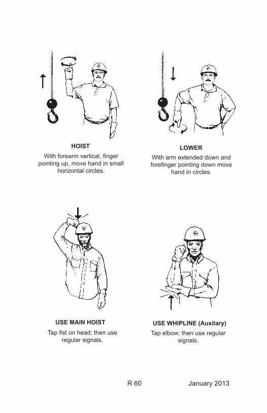
R 60 January 2013
HOISTWith forearm vertical, finger
pointing up, move hand in small horizontal circles.
With arm extended down and forefinger pointing down move
hand in circles.
LOWER
Tap fist on head; then use regular signals.
Tap elbow; then use regular signals.
USE MAIN HOIST USE WHIPLINE (Auxilary)
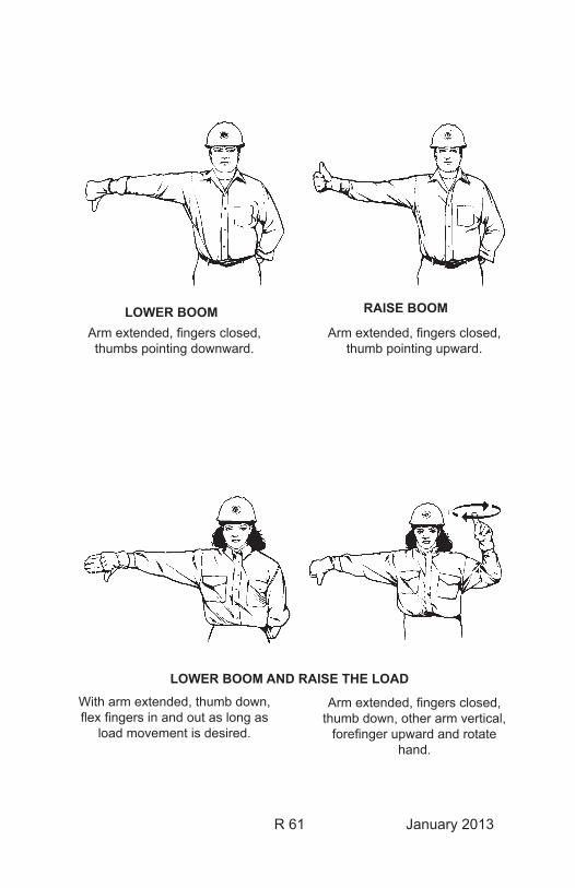
R 61 January 2013
LOWER BOOMArm extended, fingers closed, thumbs pointing downward.
Arm extended, fingers closed, thumb pointing upward.
RAISE BOOM
LOWER BOOM AND RAISE THE LOAD
With arm extended, thumb down, flex fingers in and out as long as
load movement is desired.
Arm extended, fingers closed, thumb down, other arm vertical,
forefinger upward and rotate hand.
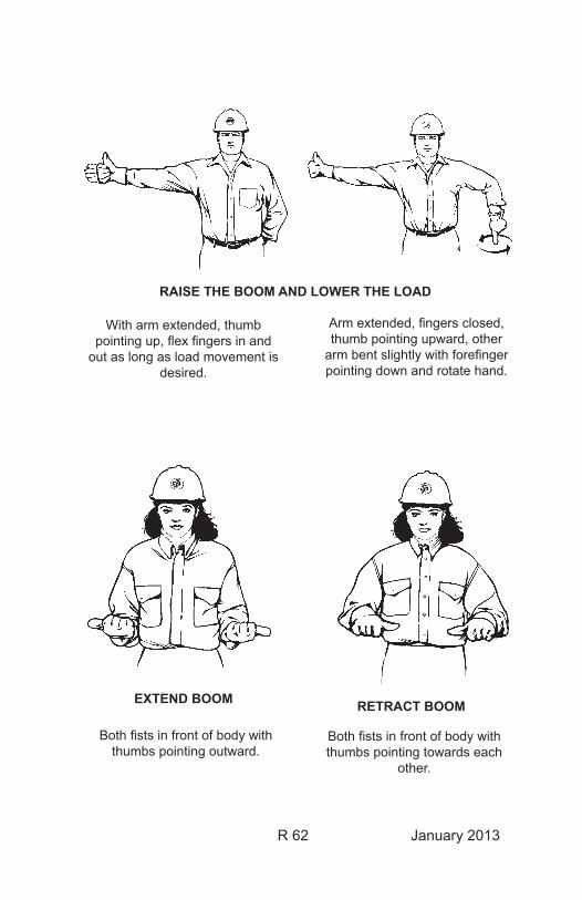
R 62 January 2013
With arm extended, thumb pointing up, flex fingers in and
out as long as load movement is desired.
Arm extended, fingers closed, thumb pointing upward, other
arm bent slightly with forefinger pointing down and rotate hand.
Both fists in front of body with thumbs pointing outward.
Both fists in front of body with thumbs pointing towards each
other.
EXTEND BOOM RETRACT BOOM
RAISE THE BOOM AND LOWER THE LOAD
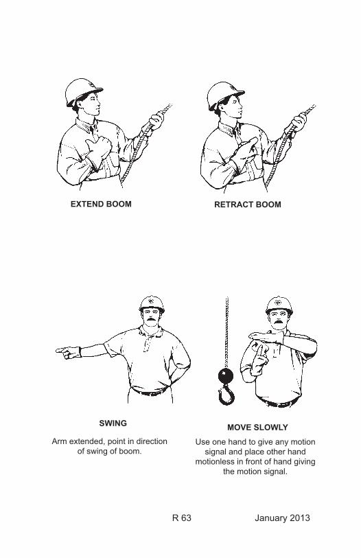
R 63 January 2013
EXTEND BOOM RETRACT BOOM
Arm extended, point in direction of swing of boom.
Use one hand to give any motion signal and place other hand
motionless in front of hand giving the motion signal.
SWING MOVE SLOWLY
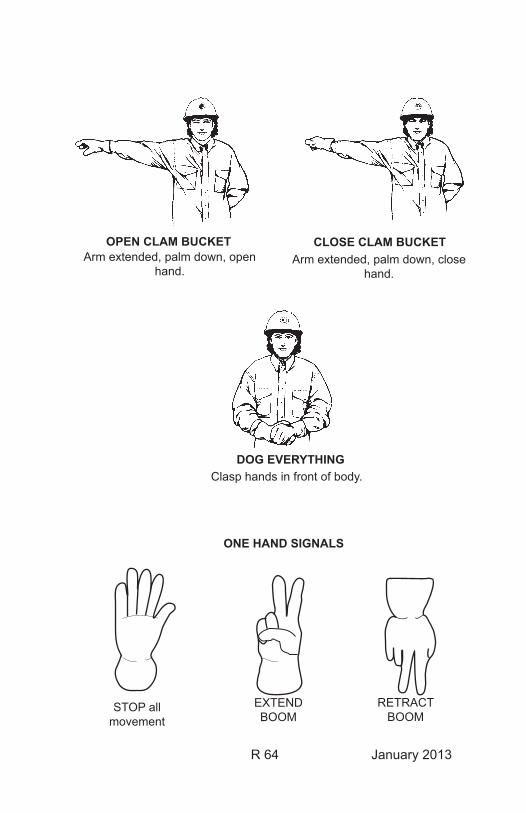
R 64 January 2013
Arm extended, palm down, close hand.
CLOSE CLAM BUCKETArm extended, palm down, open
hand.
OPEN CLAM BUCKET
Clasp hands in front of body.DOG EVERYTHING
ONE HAND SIGNALS
STOP all movement
EXTEND BOOM
RETRACT BOOM
R 65 January 2013
S-6 SWITCHING & CLEARANCE PROCEDURE (Operating Bulletin No. 2)
This is a separate and complete document which follows the Safety Rules series in this manual.
S-7 SWITCHES, ISOLATING DEVICES, ENERGIZED, RESTRICTIONS ONWork shall not be performed on one part of a high voltage switch or dis-connect if the remainder of the switch or disconnect is energized unless approved barriers are installed in accordance with Rule B-1. This does not prohibit connecting or disconnecting a bus or line to the de-energized end of a switch or disconnect if the Minimum Approach Distance (Rule M-1) is not violated. In both cases, precautions must be taken to assure that the switch cannot be operated until all work is completed.
Work may be performed on de-energized bus links, jumpers, or sectional-izing jumper couplers that are limits of a clearance provided:
• They are either removed or open and adequately restrained at all times as determined by the clearance holder.
• The minimum approach distance (Rule M-1) is not violated.• Holders of all clearances using that limit and electrical workers
involved in the work, agree the work can be completed safely. All clearance holders will be kept informed of the status of the work on the device, and
• The isolating devices shall remain tagged with “Do Not Operate” tags at all times.
S-8 SAFETY RESTRAINTS, VEHICLEVehicle safety restraints, as provided, shall be worn at all times while the vehicle is in motion. This is required when operating a leased, private, or government vehicle on official business.
Safety restraints, as provided in powered industrial equipment that is equipped with a certified roll-over protection system, must be worn.
Occupants are individually responsible for fastening and securing their safety restraints before the vehicle is in motion.
Exception: Safety restraints are not mandatory when repositioning vehicles within work locations at structures, substation yards, and garages.

R 66 January 2013
T-1 TESTING INTERVALS OF TOOLS AND EQUIPMENTIt shall be the responsibility of each district supervisor or crew foreman to ensure that all equipment is current on all required testing.
Visual inspections of all work equipment shall be done on a continuing basis prior to each use.
Testing of Portable Protective GroundsPortable protective grounds shall be tested every 2 years in accordance with BPA Work Standard BPA-WS-6-4, PPG System.
Testing of High Voltage Insulated ToolsHigh voltage insulated tools shall be tested every 2 years in accordance with BPA Work Standard BPA-WS-7-1, High Voltage Insulated Tools.
Testing of Portable Tools and EquipmentExtension cords and portable tools and equipment used in outdoor/switch-yard environments shall be tested for ground continuity on an annual basis.
IdentificationOn completion of the test, one end of each ground lead, tool, or extension cord shall be marked/tagged with colored tape in accordance with the fol-lowing code:
2008 & 2014 Blue 2011 & 2017 Yellow 2009 & 2015 White 2012 & 2018 Gray 2010 & 2016 Green 2013 & 2019 Red
Testing of Rubber Insulating Gloves and BlanketsRubber insulating gloves and blankets shall be tested in accordance with BPA Work Standard BPA-WS-7-2, Rubber Insulating Gloves and Blankets.
• Rubber insulating gloves shall be tested before first issue and every 6 months thereafter.
• Rubber insulating blankets shall be tested before first issue and every 12 months thereafter.
All rubber goods must have been electrically tested within the last 12 months prior to issue to the field.

R 67 January 2013
W-1 WELDINGThe welder on the job shall notify all workers that could be exposed to hazards involved in an arc welding process to remain in the clear or be isolated.
Workers shall not contact pieces being welded unless the pieces are elec-trically bonded together and a solid ground path to the welding machine is used.

January2013
This Page Intentionally Left Blank

January2013
CHAPTER TWO

January2013
This Page Intentionally Left Blank
CHAPTER 2
R 69 March 2011
ACCIDENT PREVENTION RULES
A-1 Access to BPA Energized Facilities
Defines the identification/certification/escorting requirements for access to and work within or around BPA energized high voltage substation facilities.
I. Employee Permits - Types and Qualifications
Permits are required for all individuals who require unescorted access or who work on or around energized substation facilities. There are three levels of employee permits: A. An Electrical Worker Permit allows unescorted access to
energized facilities by fully trained, experienced electrical individuals for performance or supervision of work on the high voltage power system.
The minimum qualifications for this permit are:
1. Need to perform, supervise/manage functions on or around
BPA energized facilities beyond those allowed by a Non-electrical or Restricted Electrical Worker Permit.
2. Knowledge and understanding of:
a. Accident Prevention Manual, b. Hazards inherent and precautions required for working
safely on a high voltage power system, and
CHAPTER 2
R 70 March 2011
c. Related electrical theory as demonstrated by a rating of
GS-9 or higher in any one of the following classifications: Electrical Engineer, Electronic Engineer or Electrical Engineering Technician.
3. Experience of one year minimum in a position with
knowledge requirements where the applicant received, issued or worked under at least three Clearances on the BPA or equivalent power system (names of holders and dates of Clearances along with identification of system, if other than BPA, are required).
B. A Restricted Electrical Worker Permit allows unescorted
access to energized facilities by individuals trained and required to perform specific, selective craft or technical functions involving work that could have an effect on the power system. Work involving the possibility of inadvertent contact with high voltage parts or the violation of Minimum Approach Distances must be performed under the direct, on-site supervision of a Qualified Electrical Employee.
The minimum qualifications for this permit are: 1. Need to perform duties on or around BPA energized facilities
beyond those allowed by a Non-electrical Worker Permit. 2. Knowledge and understanding of:
a. BPA Accident Prevention Manual, b. Hazards inherent and precautions required for working
safely on applicable parts of a high voltage power system.
3. Job title that is included in or closely related to an electrical
craft or function, such as: Electrical Engineer, Electrical Technician, Construction Representative or Electrical Trainee.
CHAPTER 2
R 71 March 2011
C. A Non-electrical Worker Permit allows unescorted access to
energized facilities by individuals who have received appropriate instructions and have demonstrated a level of understanding necessary to safely move about in energized substations. This permit allows performance of predefined work not affecting electrical operation of the power system. The minimum qualifications for this permit are: 1. Need to perform non-electric duties in or around BPA
energized facilities. 2. Knowledge and understanding of BPA’s Rules of Conduct
in energized substations. D. Non-permitted individuals requiring entry to, movement within
or who work on or around energized substation facilities will require an escort at all times by an appropriately permitted employee while in the facility. Employees who provide access to energized high voltage facilities to others not having a permit are responsible for ensuring that they are properly escorted at all times while in the facility.
II. Permits for Employees
Employees requiring unescorted access to or work on or around energized facilities must meet the minimum qualifications and examination/switchyard orientation requirements. [Reference BPA Work Standard II]]
IV. Clearance Certification
A. A Restricted Clearance Certification allows employees who
hold a Restricted Electrical Worker Permit to take Clearances and Hold Orders on BPA and foreign utility transmission lines adjacent to facilities being constructed. This is for purposes of addressing/controlling hazards of induction from, or accidental contact with adjacent energized lines.
CHAPTER 2
R 72 March 2011
Hold Orders and/or Clearances issued for these purposes do not provide access for work or contract inspection on these lines.
B. A Standard Clearance Certification allows employees who hold
an Electrical Worker Permit to: (1) take Clearances and Hold Orders, without predefined restrictions, on high voltage facilities, and (2) to issue Clearances and Hold Orders in accordance with provisions of the Switching and Clearance Procedures.
V. Withdrawal of Permits and Clearance Certifications
Withdrawal of permits and/or Clearance certifications may be affected at any time by a responsible management official. Causes for withdrawal include, but are not limited to:
1. Demonstrated lack of knowledge or unwillingness to follow
safe work practices, 2. Violation of established safety rules or procedures, 3. Documented cases showing lack of sound and mature safety
judgment, 4. Breach of substation security.
VI. Clearance Certification and Permits Directory
A current electronic list of individuals holding Permits and Clearance Certifications and a list is maintained by the Substation Operations Group, TOZ/AmpN1. This list is updated as needed and distributed to System Control Centers. Verification can be accomplished by contacting Substation Operations Group or a System Control Center.
R73 January2013
CHAPTER2
H-1 HEADPROTECTIONHardhatsapprovedbytheAdministrationshallbewornbyALLPER-SONSinthefollowinglocationsandconditionsexceptforworkinsidetransformers,powercircuitbreakers,undervehicles,orinsimilarrestrict-ed/protectedsituations:
1. Infencedsubstationyardsandotherdesignatedhardhatareas.
2. Whenengagedinorwheninthecloseproximityofoutdoorworkorinallareaswherethereisexposureaboveheadleveltomovingequipment,work,ormaterialhandling.
Identification/Color-Coding System:To distinguish between Qualified Electrical Employees and others, YEL-LOWhardhatswillberestrictedtoholdersofElectricalWorkerPermits.
Additionalhardhatcolors*utilizedontheBPAsystemare: ORANGE: ContractSafetyWatchers WHITE: AllOthers *OthercolorsutilizedarelistedinChapterOne,H-1
S-4 SAFETY WATCHERS FOR CONTRACTOR EMPLOYEESSafetyWatchersforcontractoremployeesshallberequiredinallsitua-tionsthatwouldrequireaSafetyWatcherforBPAemployees.SeeRulesS-1,S-2andS-3inChapterOneforrequirements.
Theirmainresponsibilityistolimitthemovementofcontractpersonnelorequipmenttopreventcontactwithenergizedoverheadandundergroundelectricalfacilities.IftheSafetyWatcherobservesotherunsafeworkpracticesorunsafeconditions,itistheirresponsibilitytoinformtheBPAConstructionRepresentative.SafetyWatchershavetheauthoritytohalttheoperationwheneveranyunsafeactorconditionisimminent.
TheSafetyWatchermustdemonstratequalifyingknowledgeandexperi-encebypassinganannualwrittenSafetyWatcherexaminationandoralinterviewonequipmentandworkprocessesinvolvedinthejoborbeaQualified Electrical Employee (See rule A-1).
It is the responsibility of the contracting officer’s construction site repre-sentativetoensurethattheserequirementsaremet.

R74 January2013
CHAPTER2
S-6 SWITCHING & CLEARANCE PROCEDURE (Operating Bulletin No. 2)
ThisisaseparateandcompletedocumentwhichfollowstheSafetyRulesseriesinthismanual.
January 2013
United States Department of Energy Bonneville Power Administration
System Operations
Operating Bulletin NO. 2 Accident Prevention Rule S-6
SWITCHING & CLEARANCE
PROCEDURE
January 2013
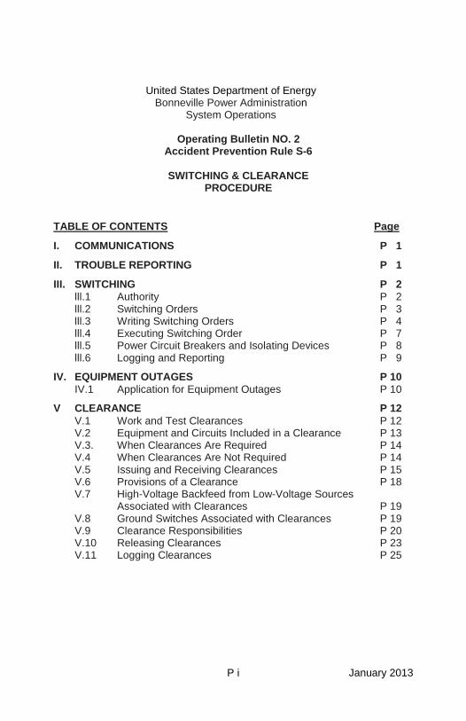
P i January 2013
United States Department of Energy Bonneville Power Administration
System Operations
Operating Bulletin NO. 2 Accident Prevention Rule S-6
SWITCHING & CLEARANCE
PROCEDURE
TABLE OF CONTENTS
I. COMMUNICATIONS P 1
Page
II. TROUBLE REPORTING P 1
III. SWITCHING P 2 lll.1 Authority P 2 lll.2 Switching Orders P 3 lll.3 Writing Switching Orders P 4 lll.4 Executing Switching Order P 7 lll.5 Power Circuit Breakers and Isolating Devices P 8 lll.6 Logging and Reporting P 9
IV. EQUIPMENT OUTAGES P 10 IV.1 Application for Equipment Outages P 10
V CLEARANCE P 12 V.1 Work and Test Clearances P 12 V.2 Equipment and Circuits Included in a Clearance P 13 V.3. When Clearances Are Required P 14 V.4 When Clearances Are Not Required P 14 V.5 Issuing and Receiving Clearances P 15 V.6 Provisions of a Clearance P 18 V.7 High-Voltage Backfeed from Low-Voltage Sources
Associated with Clearances P 19 V.8 Ground Switches Associated with Clearances P 19 V.9 Clearance Responsibilities P 20 V.10 Releasing Clearances P 23 V.11 Logging Clearances P 25
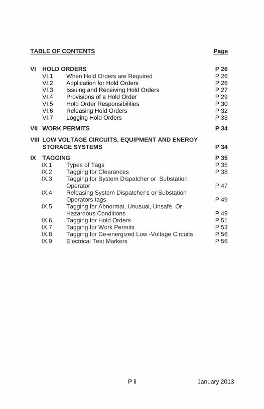
P ii January 2013
TABLE OF CONTENTS
Page
VI HOLD ORDERS P 26 VI.1 When Hold Orders are Required P 26 VI.2 Application for Hold Orders P 26 VI.3 Issuing and Receiving Hold Orders P 27 VI.4 Provisions of a Hold Order P 29 VI.5 Hold Order Responsibilities P 30 VI.6 Releasing Hold Orders P 32 VI.7 Logging Hold Orders P 33
VII WORK PERMITS P 34
VIII LOW VOLTAGE CIRCUITS, EQUIPMENT AND ENERGY STORAGE SYSTEMS P 34
IX TAGGING P 35 IX.1 Types of Tags P 35 IX.2 Tagging for Clearances P 38 IX.3 Tagging for System Dispatcher or Substation
Operator P 47 IX.4 Releasing System Dispatcher’s or Substation
Operators tags P 49 IX.5 Tagging for Abnormal, Unusual, Unsafe, Or
Hazardous Conditions P 49 IX.6 Tagging for Hold Orders P 51 IX.7 Tagging for Work Permits P 53 IX.8 Tagging for De-energized Low -Voltage Circuits P 56 IX.9 Electrical Test Markers P 56
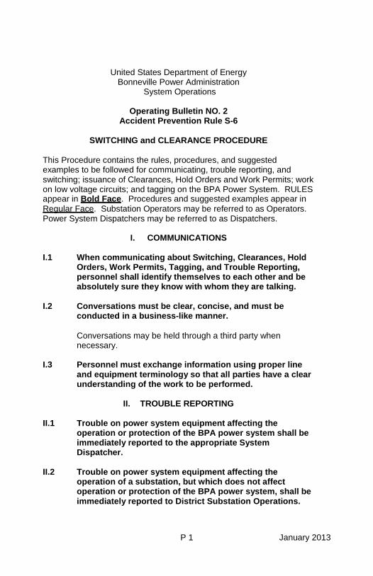
P 1 January 2013
United States Department of Energy Bonneville Power Administration
System Operations
Operating Bulletin NO. 2 Accident Prevention Rule S-6
SWITCHING and CLEARANCE PROCEDURE
This Procedure contains the rules, procedures, and suggested examples to be followed for communicating, trouble reporting, and switching; issuance of Clearances, Hold Orders and Work Permits; work on low voltage circuits; and tagging on the BPA Power System. RULES appear in Bold Face. Procedures and suggested examples appear in Regular Face. Substation Operators may be referred to as Operators. Power System Dispatchers may be referred to as Dispatchers.
I. COMMUNICATIONS I.1 When communicating about Switching, Clearances, Hold
Orders, Work Permits, Tagging, and Trouble Reporting, personnel shall identify themselves to each other and be absolutely sure they know with whom they are talking.
I.2 Conversations must be clear, concise, and must be
conducted in a business-like manner.
Conversations may be held through a third party when necessary.
I.3 Personnel must exchange information using proper line
and equipment terminology so that all parties have a clear understanding of the work to be performed.
II. TROUBLE REPORTING
II.1 Trouble on power system equipment affecting the
operation or protection of the BPA power system shall be immediately reported to the appropriate System Dispatcher.
II.2 Trouble on power system equipment affecting the
operation of a substation, but which does not affect operation or protection of the BPA power system, shall be immediately reported to District Substation Operations.
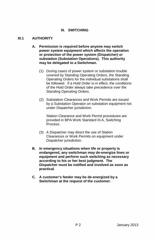
P 2 January 2013
III. SWITCHING III.1 AUTHORITY
A. Permission is required before anyone may switch
power system equipment which affects the operation or protection of the power system (Dispatcher) or substation (Substation Operations). This authority may be delegated to a Switchman.
(1) During cases of power system or substation trouble
covered by Standing Operating Orders, the Standing Operating Orders for the individual substations shall be followed. If a Hold Order is in effect, the conditions of the Hold Order always take precedence over the Standing Operating Orders.
(2) Substation Clearances and Work Permits are issued
by a Substation Operator on substation equipment not under Dispatcher jurisdiction.
Station Clearance and Work Permit procedures are provided in BPA Work Standard III.A, Switching Process.
(3) A Dispatcher may direct the use of Station
Clearances or Work Permits on equipment under Dispatcher jurisdiction.
B. In emergency situations when life or property is
endangered, any switchman may de-energize lines or equipment and perform such switching as necessary according to his or her best judgment. The Dispatcher must be notified and involved as soon as practical.
C. A customer’s feeder may be de-energized by a
Switchman at the request of the customer.
P 3 January 2013
III.2 SWITCHING ORDERS
A. A Switching Order is required, unless specifically ordered otherwise by the Dispatcher:
(1) For all switching and/or tagging involving the
issuance and release of Clearances. (2) For Hold Orders on lines involving the positioning
of adjustable rod gaps. When required, the Dispatcher shall include the
adjustment of the rod gaps to minimum spacing in the instructions before issuing a Hold Order for hot-line maintenance, and readjustment of the rod gaps to maximum spacing after the Hold Order is released.
(3) For all high-voltage switching and/or tagging
while in a substation switchyard.
An example of “or tagging” includes checking open and tagging an isolating device or removal of those same tags.
(4) Anytime a Dispatcher or Substation Operator
requires a Switching Order for equipment under Dispatcher or Substation Operations jurisdiction.
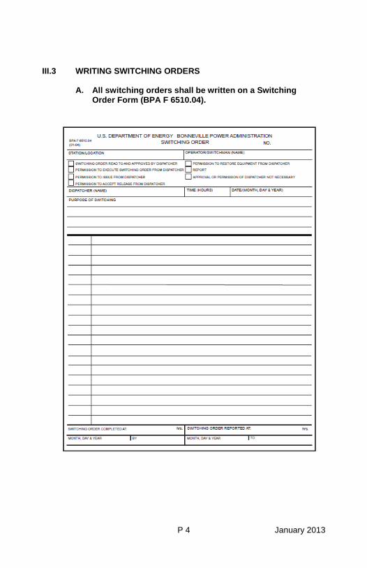
P 4 January 2013
III.3 WRITING SWITCHING ORDERS
A. All switching orders shall be written on a Switching Order Form (BPA F 6510.04).
P 5 January 2013
B. Switch Order Requirements.
(1) Each step of a Switching Order shall be started on a separate line. If the sequence of operation is not important, the opening of more than one disconnect switch or the closing of more than one disconnect switch may be included in a single step.
(2) No erasures shall be made on Switching Orders.
No lines shall be skipped and no additions or insertions shall be made between lines. If information is written incorrectly and immediately noticed, a line may be drawn through the incorrect portion, initialed, and the correct instruction written immediately following the deleted portion Otherwise the Switching Order shall be voided and a new one written.
(3) The Switching Order Form heading and ending
shall be completely filled in. (4) The Dispatcher may require the Switchman to
read the Switching Order for approval. Unless clarification or revision is necessary, the Dispatcher is not required to repeat back the order in detail.
(5) The Dispatcher may order a single line in the
Switching Order lined out and initialed, order a line added at the end of a Switching Order (e.g., ground switch), or order the Switching Order voided and a new one written.
(6) Once the Switching Order has received approval
or permission to execute, no changes or additions shall be made.
C. Preparing a Switching Order
(1) Before writing a Switching Order, pre-switching inspections shall be performed. Pre-switching inspections may only be waived as directed by the Dispatcher during trouble situations or emergencies. (Refer to BPA Work Standard III.A, Switching Process).
P 6 January 2013
Pre-switching inspections includes checking outstanding station conditions; existing Clearances, Work Permits, tagging; mimic bus setup, bus voltage, panel indications and panel metering; station log book, alarm status, relay targets; and ensuring operational readiness of equipment to be switched.
(2) Utilize available resources in preparing the Switching Order.
These include station prints, Station Instructions, Operating Bulletins, BPA Work Standards, other crafts, Dispatcher, other District Operators, etc.
(3) Relay protection and stability control schemes (RAS) affected by switching must be checked prior to writing a Switching Order. Switchmen must check for proper relay protection including correct relay selector switch, relay transfer switch and stability control (RAS) switch positions. They must determine what effect the switching will have on current and/or voltage sources to relays and control equipment. If a switchman writing a Switching Order encounters problems or is in need of information or advice, the Dispatcher or District Substation Operations should be consulted.
(4) In preparing to write the Switching Order, mentally and/or physically walk through the switching.
For example, review the switching with the mimic bus, with a station One-line Diagram or by physically walking through the switching.
(5) Only approved abbreviations shall be used in writing Switching Orders. Refer to BPA Work Standard III.A, Switching Process.
(6) Additional switching order requirements are
provided in BPA Work Standard III.A, Switching Process.
P 7 January 2013
III.4 EXECUTING SWITCHING ORDERS
A. All Switching Orders on the BPA power system shall be executed by Switchmen.
(1) The Dispatcher has authority to issue emergency
orders to be carried out at once even though a previous Switching Order is in progress.
(2) If it becomes necessary to write and execute a
second Switching Order before a previous Switching Order is completed, Dispatchers and Switchmen must proceed with extreme care to avoid conflicts and errors.
(3) If it becomes necessary for a Switchman to perform a
Switching Order written by another Switchman, the Switchman who is to perform the switching must review the Switching Order before starting the switching. That Switchman will signify that a review has been made and that he or she understands and agrees with the switching procedure by placing their initials after the last line of the Switching Order.
(4) If the Switchman performing the switching is in need
of information or advice, the Dispatcher should be consulted.
B. Only approved abbreviations as listed in Work
Standard III.A, Switching Process shall be used during communications. Verbal short cuts and verbal abbreviating shall not be used.
C. Each isolating device to be operated or checked shall
be identified by its designated System Operations number, name, and/or location, e.g., B-1212 line side disconnect, A-828 main bus sectionalizing disconnect. Each low voltage device shall be identified by its designated substation number, name, and/or location.
Immediately prior to operating any isolating device, the Switchman shall check the dispatcher number and/or name of the isolating device to be operated against the Switching Order and make sure they agree. Where possible, the Switchman shall also check that the isolating device is in the proper position before operating it.
P 8 January 2013
D. The Switchman shall perform the switching steps in
the same sequence as written in the Switching Order. E. The Switchman shall carry the Switching Order while
performing the switching, and shall check off each step as it is completed.
F. If, while executing a Switching Order, an isolating
device is found to be in a position other than that expected or anticipated or the Switchman has reason to believe any further switching would be improper, no further switching shall be done until the System Dispatcher or Substation Operator is consulted.
G. The System Dispatcher or Substation Operator shall promptly be informed whenever a switching operation or Switching Order is completed.
H. Additional switching practices are addressed in BPA
Work Standard III.A, Switching Process.
III.5 POWER CIRCUIT BREAKERS AND ISOLATING DEVICES
A. Power Circuit Breakers. (1) The Switchman shall ensure operational
readiness prior to switching.
Operational inspections prior to and after the operation of power circuit breakers are provided in BPA Work Standard III.B, Equipment Operation.
An inspection is performed prior to switching
any time the breaker has operated due to relay action, or when the pre-switching inspection indicates a need.
B. Isolating Devices
(1) The Switchman shall ensure operational readiness prior to switching. Inspection of isolating devices is made just
prior to operation.
P 9 January 2013
Operational requirements and switching safety
prior to and during operation is provided in BPA Work Standard III.A, Switching Process.
Operating inspections, characteristics,
capabilities, switching processes, and Powerflow Study requirements for isolating devices with or without attachments are addressed in BPA Work Standard III.B, Equipment Operation (including Table 2, Switching Device Capabilities).
III.6 LOGGING AND REPORTING
A. All switching operations shall be recorded in the
Substation Log Book with the following specific information in the exact order executed.
The Log entry shall include:
(1) The date and time of starting the switching. (2) The switching Order number. (3) The name of the Dispatcher or Substation Operator
approving or granting permission to execute the Switching Order.
(4) The Switchman’s name. (5) The purpose of the switching. (6) The times of all major operations of the switching
order. (7) The time the Switching Order was completed. (8) The time the Switching Order was reported, the name
of the person reporting, and the Dispatcher or Operator to who reported.
B. The operation of all ground switches shall be
recorded in red in the Substation Log Book.
P 10 January 2013
C. Only approved abbreviations shall be used when writing in the Substation Log Book. Refer to BPA Work Standard III.A, Switching Process.
IV. EQUIPMENT OUTAGES
IV.1 APPLICATION FOR EQUIPMENT OUTAGES
A. Applications for Clearances, Hold Orders and Work Permits for equipment outages affecting the operation or protection of the BPA power system shall be made with the appropriate Outage Dispatcher as far in advance as possible. Minimum Advance Notice Requirements for prearranged high voltage equipment outages are: (1) Significant Equipment – 45 days prior to the start of
the month in which the outage will occur (see OB19). (2) Non-Significant Equipment
(a) Power System Tests - 30 working days (b) Customer Interruptions - 7 working days (c) All Other Transmission Circuits - 3 working days (d) All other transmission circuits and bus outages
not requiring a line outage – 3 working days prior to day of work (This includes all equipment 100 kV and above that is to be bypassed or removed from service).
(e) All Hold Orders not requiring a line outage – 3
working days prior to day of work. * (f) All other outages including fiber optics – 3
working days prior to day of work. *
* Outages must be submitted to the appropriate Outage Office by 0800 hours 3 working days prior to day of work.
Emergency equipment outage request will be processed by the appropriate Dispatcher under real time procedures.
P 11 January 2013
B. Applications for Clearances and Work Permits for
equipment outages which do not affect the operation or protection of the BPA power system shall be made with District Substation Operations as far in advance as possible.
When applying for a Clearance or Work Permit, the following information is to be provided to the Outage Dispatcher or Chief Substation Operator:
(1) The correct name designation of the line or equipment
desired, using System Operations numbers and designations.
(2) The date and time the work or test requiring the
Clearance, or Work Permit is scheduled to begin. (3) The anticipated duration required for the Clearance or
Work Permit. (4) The name of the person who will take the Clearance
or Work Permit. (5) The type of Clearance desired. (6) A description of the work or test to be performed.
C. Application for Clearance and Hold Orders from
foreign utilities to facilitate BPA’s work in proximity to the foreign utility’s equipment (V.5G and VI.3D) shall be made as far in advance as possible.
When applying for a Clearance and Hold Order from a
foreign utility, the following information shall be provided to the Outage Dispatcher or Chief Substation Operator:
(1) The correct name designation of the line or
equipment as identified by the foreign utility. (2) The date and time the work requiring the
Clearance or Hold Order is scheduled to begin. (3) The anticipated duration for the Clearance or Hold
Order.
P 12 January 2013
(4) The name of the person who will take the
Clearance or Hold Order. (5) A description of the work to be performed. (6) Whether the recipient will receive/release the
Clearance or Hold Order directly through the foreign utility.
(7) Contact information of the foreign utility.
For further information on application for a Clearance or
Hold Order from a foreign utility, see BPA Work Standard III.E, Clearance and Hold Orders from Foreign Utilities.
D. All Craft supervisors shall keep informed of
proposed/submitted/scheduled outages through the Daily Activity Record Tracking (DART). Chief Operators shall serve as consultants/coordinators for the details/possibilities of those outages. The scheduling of maintenance work must be coordinated to minimize the number of outages to BPA lines and equipment and to customers’ points of delivery.
V. CLEARANCES
V.1 WORK and TEST CLEARANCES
A. There are two types of Clearances and the activity
determines the type of Clearance needed. (1) A WORK CLEARANCE provides protection when
work is to be performed on de-energized high voltage lines or equipment. Electrical tests may be performed on equipment included in a Work Clearance if: (a) The high voltage equipment is contained in a
substation. (b) The equipment is under the physical control
of the Clearance Holder. (c) AND the equipment is separated from the rest
of the de-energized high voltage equipment in
P 13 January 2013
the Clearance by means sufficient to positively prevent the test voltages and/or currents from entering the remainder of the equipment protected by the Clearance.
(2) A TEST CLEARANCE provides protection when
electrical tests are to be performed on high voltage equipment and the conditions required for application of electrical tests under a Work Clearance in A (1), (a), (b), or (c) cannot be met.
B. More than one WORK CLEARANCE may be issued on
the same line or equipment to multiple crews. C. Under the following circumstances more than one
WORK CLEARANCE may be issued to members of the same crew for work on the same equipment: (1) If the expected duration of the work is one month
or more, a second Clearance Holder may be requested at the time the outage request is made.
(2) Transformer dry-outs (or similar type work) where
work occurs around the clock or during significantly extended workdays where one Clearance Holder must relieve another Clearance Holder because of the on-going nature of the work. A second and, if necessary, third Clearance Holder could be requested at the time the outage request is made for this type of work.
D. Only one TEST CLEARANCE may be issued on the
same line or equipment. V.2 EQUIPMENT AND CIRCUITS INCLUDED IN A CLEARANCE
When a Clearance is issued, it will include all of the high-voltage circuits and equipment within the limits of the Clearance and jurisdiction over low-voltage circuits within the equipment, which can be isolated at the high-voltage equipment.
P 14 January 2013
If the holder of the Clearance will need jurisdiction over more of the low-voltage circuitry than is normally included, these additional circuits should be requested to be tagged for the Clearance Holder.
V.3 WHEN CLEARANCES ARE REQUIRED
A. A WORK CLEARANCE or a TEST CLEARANCE is
required:
(1) Before workers contact or come within the applicable Minimum Approach Distance of any line or equipment that could become energized by the closing of an isolating device.
(2) Before any line or equipment may be installed or
removed when energization of the line or equipment could result by the closing of an isolating device.
A Clearance or Hold Order, as appropriate, is
required during the time isolating devices are being put in place to make connection to the power system.
(3) Before installing or removing any conductor
which crosses over or under normally energized lines or equipment unless the work can be accomplished under the protection of a Hold Order.
B. A TEST CLEARANCE is required before electrical test
voltages and/or currents may be applied to any equipment that could become energized by the closing of an isolating device AND the conditions required for application of electrical tests under a Work Clearance cannot be met.
V.4 WHEN CLEARANCES ARE NOT REQUIRED
A. New Construction
During the construction of new facilities, a Clearance is not required if power system equipment is not in place to provide a connection to the power system by the closing of an isolating device.
P 15 January 2013
B. Return to Construction Status Return to Construction Status: Reconductoring of existing lines, removal and/or replacement of facilities, or for other similar type work. A Clearance is not required for this work providing that a letter requesting the work to be accomplished without a Clearance has been submitted to and approved in writing by the Manager of the Dispatching Office having jurisdiction over the equipment. Under the protection of a Clearance, the facilities will be separated from all possible sources of energization by the physical removal of the predefined circuit parts such as risers, wire spans, bus work, or other conductor, which completely separates the equipment from the power system. BPA Work Standard III.C, Work on Equipment Separated From the System, is an extension of OB2, Section V.4, When Clearances are not required.
V.5 ISSUING AND RECEIVING CLEARANCES
A. All Clearances on the BPA power system shall be
issued by a System Dispatcher or Substation Operator. The System Dispatcher or Substation Operator may delegate the authority to issue Clearances to a Switchman. The Dispatcher or Operator having jurisdiction over the facilities that are cleared, is responsible for issuance of the Clearance. (1) A Dispatcher’s Clearance is issued by or with the
permission of the Dispatcher who has jurisdiction over the facilities that are cleared.
(2) A Station Clearance is issued by an Operator who
has jurisdiction over the facilities that are cleared. B. When more than one Clearance is issued or is to be
issued on a transmission line or associated terminal equipment, each Clearance Holder shall be given the names of the other Clearance Holders and advised of the type of work that each Clearance Holder will be performing. All Clearance Holders shall be informed of this at the time of receiving their Clearance. Existing Clearance Holders shall be advised of
P 16 January 2013
additional Clearance requests prior to the issuance of any new Clearance(s).
C. In emergencies when no communications are
available, Switchmen may do necessary switching and tagging and issue Clearances to themselves.
D. Clearances will be issued to employees for whom a
Clearance Certification is on file with the Dispatchers.
When issuing a Clearance, the Dispatcher or Operator shall state clearly to the person receiving the Clearance: (1) The name of the person receiving the Clearance. (2) The exact name of the line or equipment at the job
site that is cleared and tagged. (3) The type of Clearance being issued. (4) The Clearance number. (5) The status of available ground switches. Example: “John Doe, the Central-East Columbia No. 3
230-kV line is cleared and tagged for you on Work Clearance No. D-4567W, and ground switches at Central and East Columbia are closed.”
When receiving a Clearance, the Clearance Holder shall repeat back to the Dispatcher or Operator: (1) The name of the person receiving the Clearance. (2) The exact name of the line or equipment at the job
site that is cleared and tagged. (3) The type of Clearance being received. (4) The Clearance number. (5) The status of available ground switches.
P 17 January 2013
Example: “This is John Doe and I understand that the Central-East Columbia No. 3 230-kV line is cleared and tagged for me on Work Clearance No. D-4567W, and ground switches at Central and East Columbia are closed.”
E. When a Clearance is received on equipment in a
substation, it shall be the Clearance Holder’s responsibility to go with the Switchman to: (1) Point out the specific limits of the Clearance. (2) Point out which facilities are included in the
Clearance. (3) Point out specific hazards in the work area
presented by energized circuits and equipment.
It shall be the Switchman’s responsibility to assure that the above information the Clearance Holder gives is correct. If the Switchman is not present when the Clearance is issued, the Clearance Holder will assure that his/her understanding of the above information is correct by touring the Clearance site and checking the tagged isolating devices before any work associated with the Clearance begins. Other persons present who will work under the Clearance should, where practical, be included in the tours as an aid to fulfilling the Clearance Holder’s responsibilities described in V.9.
F. When BPA crews work on lines or equipment under
foreign jurisdiction, they will receive Clearances in accordance with the foreign utility’s rules and procedures.
G. A Clearance issued to a BPA employee by a foreign
utility on their line or equipment is issued according to that utility’s rules and procedures. This process is accomplished by either of the following:
P 18 January 2013
(1) The BPA Dispatcher can receive the Clearance from the foreign utility and in turn issue a Clearance to the BPA crew, or
(2) The Clearance can be issued directly to a BPA
employee from the foreign utility. When BPA crews require a Clearance on lines or equipment under a foreign utility’s jurisdiction for proximity work on a BPA project, a BPA Dispatcher will issue the Clearance, Or In those cases where the foreign utility’s determination is to issue directly to a BPA employee, the recipient of the Clearance from the foreign utility shall inform the BPA Dispatcher of the following upon the receipt of the Clearance and before beginning work requiring the protection of a Clearance:
Name of foreign utility and issuing employee Time received Foreign utility and foreign utility’s circuit
identification Work location with respect to BPA transmission
line Date, time, and duration of Clearance on the
foreign utility’s line or equipment V.6 PROVISIONS OF A CLEARANCE
With the issuance of a Clearance, the Dispatcher or Substation Operator gives assurance that:
A. The lines or equipment are separated from the power
system with isolating devices. B. All isolating devices are open, made non-operative
and tagged.
P 19 January 2013
C. None of the tags will be ordered removed and none of the isolating devices will be ordered closed until the Clearance has been released.
V.7 HIGH-VOLTAGE BACKFEED FROM LOW-VOLTAGE
SOURCES ASSOCIATED WITH CLEARANCES For the purpose of controlling energization of the high-voltage equipment included within the Clearance from potential backfeed through low-voltage sources, such as an alternate station service, an engine generator, or as otherwise determined by the Substation Operator, the secondary circuit low-voltage isolating device(s) shall be opened and tagged with a Do Not Operate tag for the Clearance Holder.
V.8 GROUND SWITCHES ASSOCIATED WITH CLEARANCES A. Ground switches associated with Clearances shall be
closed unless otherwise agreed among all Clearance applicants on that facility and the Dispatcher or Substation Operator.
B. Ground switches associated with Clearances shall be
closed unless permission has been granted by the Dispatcher or Substation Operator to open ground switches to work on them, provided that portable protective grounds have been installed as substitutes for the ground switches.
C. The recipient of the Clearance will be informed of
ground switch status at the time the Clearance is issued.
D. The position of any ground switch associated with a
transmission line with multiple Clearance Holders will not be changed until each Clearance Holder on that line has been notified by the Dispatcher and given the opportunity to get personnel in the clear. In the event one crew working on a line with multiple Clearance Holders experiences a step and touch potential problem and requests that a ground switch be opened, portable protective grounds shall not be installed as substitutes for the open ground switch.
P 20 January 2013
E. Ground switches associated with Test Clearances may be operated by the holder of the Test Clearance without permission of the Dispatcher or Substation Operator.
V.9 CLEARANCE RESPONSIBILITIES
A. Clearance Holder Responsibilities
The following responsibilities apply to any holder of a clearance. Additional responsibilities for electrical work or Work Clearances taken for non-electrical work only are provided in B and C below. (1) Shall know the type and limits of the Clearance,
the facilities included, and the status of ground switches within the Clearance. The Clearance Holder shall also know the Clearance number, the time of issue, and the name of the Dispatcher or Substation Operator who issued the Clearance.
(2) Shall know the Low-Voltage Isolating Devices that are
the limits of a Clearance.
If work is to be performed on the low-voltage equipment included within the Clearance limits, appropriate Lockout/Tagout procedures shall be followed.
(3) The Clearance Holder shall convey this
information (in 1 and 2 above) to all persons working under that Clearance before work begins. In addition, any specific hazards associated with the work shall be pointed out.
(4) At the time of receipt of their Clearance, shall
know the name(s) of other Clearance Holders and the type of work they are accomplishing when more than one Clearance is issued on the same transmission line.
This procedure is to prevent job site changes in step and touch potentials due to an unannounced change in grounding.
(5) Shall direct the application of protective grounds
in accordance with the Grounding Rules before
P 21 January 2013
allowing any workers to touch or come within the applicable Minimum Approach Distance of normally energized electrical parts.
(6) Shall direct the installation of barriers or guards
as necessary to prevent accidental contact with adjacent energized facilities before allowing work to begin in areas where such hazards exist.
(7) Shall utilize Safety Watchers as required in the
Safety Watching Rules. (8) Shall remain at the job site while work or testing
is being performed on equipment under a Clearance.
B. Clearance taken for electrical work, the Clearance
Holder:
(1) When test voltages and/or currents are to be applied to equipment under a Work Clearance, the Clearance Holder shall: (a) Separate the equipment to be tested from the
rest of the de-energized high voltage equipment in the Clearance by means sufficient to positively prevent the test voltages and/or currents from entering the remainder of the equipment protected by the Clearance.
(b) Attach Electrical Test Markers to the
equipment to be tested as close to the points of separation as possible.
(c) Notify the Clearance Holders in the immediate
area that electrical tests are to be performed. (d) Supervise or perform the electrical tests. (e) Remove the Electrical Test Markers and notify
other Clearance Holders in the immediate area when the electrical tests are complete.
(2) Protective grounds attached to equipment which will
be tested (work or test Clearances) may be detached
P 22 January 2013
during the time test voltages are being applied. No other work than is necessary for application of the electrical tests may be done on that piece of equipment while the protective grounds are removed.
C. Work Clearances taken for non-electrical work only,
the Clearance Holder: (1) Shall act as Safety Watcher for the crew or assure
himself/herself that there is a qualified person to act as Safety Watcher.
(2) Shall remain at the substation while work on
equipment under the Clearance is being done if not acting as the Safety Watcher. The Clearance Holder must tell the crew and the Safety Watcher what he/she will be doing and where he/she will be located at all times while the work requiring the Clearance is being done. The Clearance Holder may do other work but must be available to the crew and the Safety Watcher. As a minimum the Clearance Holder will meet with the crew and the Safety Watcher every 4 hours while work is in progress to exchange information about the work or other issues.
D. The Workers:
(1) Shall know the type and limits of the Clearance,
the facilities included, and the status of ground switches within the Clearance. The Workers shall verbally acknowledge to the Clearance Holder, the Clearance number, the time of issue, and the name of the Dispatcher or Substation Operator who issued the Clearance. In addition, they shall understand any specific hazards that may be associated with the work.
Shall know that all Low-Voltage Isolating Device ACBs that are limits of the Clearance have been tested open before touching or coming within the applicable Minimum Approach Distance of normally energized electrical parts.
(2) Shall be certain that protective grounds are
applied before contacting or coming within the
P 23 January 2013
applicable Minimum Approach Distance of normally energized parts.
(3) Shall heed all barriers and guards, and obey all
warning signs. (4) Shall request a Safety Watcher when one is
required. (5) Shall cease work or tests on equipment under the
Clearance when the Clearance Holder is not at the job site for electrical work, or the Clearance Holder is not at the substation or unavailable for non-electrical work.
V.10 RELEASING CLEARANCES
A. All Clearances must be promptly released when the
work or test is completed. B. The System Dispatcher may delegate authority to a
Switchman to accept the release of Dispatcher’s numbered Clearances.
C. When a Clearance Holder releases a Clearance on a
line or equipment that is ready for service, the Dispatcher or Switchman must be assured that: (1) All workers and equipment are in the clear. (2) All portable protective grounds have been
removed. (3) The released line or equipment is ready for
service. (4) All isolating devices and ground switches within
the limits of the Clearance have been left in the same position as found.
When a Clearance is to be released on a line or equipment that is ready for service, the Clearance Holder shall personally report to the Dispatcher or Switchman to whom the Clearance is to be released and shall make a statement similar to the following:
P 24 January 2013
“This is John Doe at Central Substation and I am ready to release my Test Clearance number D-6789T on Transformer No. 2. My crew and equipment are in the clear, my protective grounds are removed, the work is completed, and as far as I am concerned Transformer No. 2 is ready for service. All isolating devices and ground switches within the limits of the Clearance are in the same position as found.” The Dispatcher or Switchman will repeat back to the Clearance Holder all of the information just provided. Upon acceptance of the release, the Clearance no longer exists.
D. When a Clearance issued by a foreign utility to a BPA employee is released back to the foreign utility, the recipient of the Clearance from the foreign utility shall promptly report the following to the BPA Dispatcher: • Name of foreign utility and their receiving
employee • Time released • Foreign utility’s circuit identification • Plans for future needs on the foreign utility’s line
or Equipment
E. When a Clearance Holder releases a Clearance on a line or equipment that is NOT ready for service, the Dispatcher or Switchman must be assured that all workers are in the clear, and be informed of: (1) The condition of the line or equipment.
The Clearance Holder must advise the Dispatcher or Switchman that it is available for limited or emergency service only, or that it is not available for service.
(2) The status or location of protective grounds. (3) The plans for a future Clearance on the line or
equipment.
P 25 January 2013
(4) The position of isolating devices and ground switches within the limits of the Clearance that is being released.
When a Clearance is to be released on a line or equipment that is not ready for service, the Clearance Holder shall personally report to the Dispatcher or Switchman to whom the Clearance is to be released and shall make a statement similar to the following: “This is John Doe at Central Substation and I am ready to release my Test Clearance number D-6789T on Transformer No. 2. My crew is in the clear, but Transformer No. 2 is not ready for service. My protective grounds are in place on the 230-kV, 115-kV, and 13.8-kV sides of the transformer. The work is scheduled to be continued tomorrow with a new Test Clearance to be issued to Jim Smith. All isolating devices and ground switches within the limits of the Clearance are in the same position as found.” The Dispatcher or Switchman will repeat back to the Clearance Holder all of the information just provided. Upon acceptance of the release, the Clearance no longer exists.
F. If a Clearance Holder is unable to release a Clearance,
the immediate supervisor of that Clearance Holder shall communicate with the crew, release the Clearance, and designate the person who will receive the new Clearance.
V.11 LOGGING CLEARANCES
A. All switching and tagging done for the issuance and
release of a Clearance shall be recorded in the Substation Log Book.
B. Clearances issued by or released to a Switchman
other than a Dispatcher shall be recorded in red in the Substation Log Book.
P 26 January 2013
VI. HOLD ORDERS VI.1 WHEN HOLD ORDERS ARE REQUIRED
The purpose of a Hold Order is to get personnel in the clear. A. Hold Order Is Required:
(1) While performing hot-line work. (2) While falling danger trees if an electrical hazard
could result. (3) While installing or removing any conductor which
crosses over or under normally energized high-voltage circuits. If the work cannot be accomplished under the protection of a Hold Order, a Clearance must be obtained.
(4) While removing or replacing hot-stick links on
normally energized high-voltage facilities. (5) While proximity work is in progress during line
construction. (6) While testing or washing insulators “hot”. (7) While equipment is being operated near energized
high-voltage facilities and there is the possibility of accidental contact or violation of the applicable Minimum Approach Distance.
(8) While performing approved bare-hand
procedures. VI.2 APPLICATION FOR HOLD ORDERS
Applications for Hold Orders shall be made with the appropriate Outage Dispatcher as far in advance as possible. Minimum Advance Notice Requirement for a prearranged Hold Order is 3 working days preceding the work.
P 27 January 2013
Example: “Applications shall be made to the appropriate Outage Dispatcher for Outages by 1500 hours on Tuesday for scheduled work on Friday”.
When applying for a Hold Order, the following information is to be provided to the Outage Dispatcher: A. The correct name designation of the line or equipment
requiring a Hold Order, using System Operations numbers and designations.
B. The date and time the work requiring the Hold Order is
scheduled to begin. C. The anticipated duration the Hold Order will be required. D. The name of the person who will take the Hold Order. E. A description of the work to be performed. F. The means of communication which will be available
during the Hold Order. VI.3 ISSUING AND RECEIVING HOLD ORDERS
The Dispatcher shall order automatic reclosing cut-out and tagged, and all other control points tagged for a Hold Order. When all procedures have been completed for the provisions of the Hold Order, the Dispatcher shall issue the Hold Order to the worker and the hot-line maintenance or proximity work can proceed. A. All Hold Orders on the BPA power system shall be
issued by a System Dispatcher. Authority to issue Hold Orders may be delegated to a Substation Operator. When issuing a Hold Order, the Dispatcher or Operator shall state clearly to the person receiving the Hold Order: (1) The name of the person receiving the Hold Order.
P 28 January 2013
(2) The exact name of the line or equipment included in the Hold Order.
Example: “John Doe, you now have a Hold Order on the
Central-East Columbia No. 2 230-kV line.”
B. Hold Orders will be issued to employees for whom a Clearance Certification is on file with the Dispatchers. When receiving a Hold Order, the recipient of the Hold Order shall repeat back to the Dispatcher or Substation Operator: (1) The name of the person receiving the Hold Order. (2) The exact name of the line or equipment included
in the Hold Order.
Example: “This is John Doe, and I now have a Hold Order on the Central-East Columbia No. 2 230-kV line.”
The Dispatcher or Operator and the recipient of the Hold Order shall confirm the location of the crew and the communication, which will be available for the duration of the Hold Order.
C. When BPA crews require a Hold Order for work on
lines or equipment under foreign jurisdiction, they will receive Hold Orders in accordance with the foreign utility’s rules and procedures.
D. A Hold Order issued to a BPA employee by a foreign
utility on their line or equipment is issued according to that utility’s rules and procedures. This process is accomplished by either of the following:
(1) The BPA Dispatcher can receive the Hold Order
from the foreign utility and in turn issue a Hold Order to the BPA employee, or
(2) The Hold Order can be issued directly to a BPA
employee from the foreign utility.
P 29 January 2013
(Refer to BPA Work Standard III.E, Clearance and Hold Orders from Foreign Utilities for an example and discussion of each process.)
When BPA crews require Hold Orders on lines or equipment under a foreign utility’s jurisdiction for proximity work on a BPA project, the BPA Dispatcher will issue the Hold Order, except in those cases where the foreign utility’s rules and procedures dictate that the utility will issue the Hold Order.
Or
In those cases where the foreign utility’s determination is to issue directly to a BPA employee, the recipient of the Hold Order from the foreign utility shall inform the BPA Dispatcher of the following upon receipt of the Hold Order and before beginning work requiring the protection of a Hold Order:
• Name of foreign utility and issuing employee • Time received • Foreign utility’s circuit identification work location
with respect to BPA transmission line • Date, time and duration of Hold Order on the foreign
utility’s line or equipment VI.4 PROVISIONS OF A HOLD ORDER
With the issuance of a Hold Order, the Dispatcher or Substation Operator gives assurance that: A. Protective relays are in service at all terminals, which
will adequately protect the circuit for all types of faults.
B. Automatic reclosing of power circuit breakers that
protect the line or equipment has been disabled by manually placing or checking the reclosing relay cut-off switch in the “off” position, or Automatic reclosing and the close circuits* of the power circuit breaker(s) that protect the line or equipment have been disabled or checked disabled remotely by a System Dispatcher.
P 30 January 2013
* Close circuits that would prevent the closing of the PCB(s)
at the station by the control switch. SCADA will have full operational control of the PCB(s) while the Hold Order is in place.
C. An “Assurance of no backfeed” or a “Terminal Hold”
has been obtained on all interconnections with a customer or other utility.
D. If the Hold Order is requested for hot-line
maintenance, all adjustable rod gaps on that line have been reduced to their minimum spacing and properly tagged.
In those cases where a foreign utility has requested a Hold Order from BPA for work on the utility’s line, the foreign utility’s rules and procedures will determine whether the adjustable rod gaps spacing needs to be reduced on the BPA terminal.
E. All control points have been properly tagged to
prevent energization of the lines or equipment included in the Hold Order if they are de-energized by terminal relay action.
F. The lines or equipment will not be energized until the
Holder of the Hold Order reports the crews in the clear.
VI.5 HOLD ORDER RESPONSIBILITIES
A. The person receiving the Hold Order:
(1) Shall know the exact name of the line or
equipment of the Hold Order as well as the facilities included in it. That person shall also know the time of issue, and the name of the Dispatcher or Substation Operator who issued the Hold Order.
(2) Shall verbally convey this information to all
persons working under that Hold Order.
P 31 January 2013
(3) Shall direct installation of barriers or guards as necessary to prevent accidental contact with adjacent energized facilities before allowing work to begin in areas where such hazards exist.
(4) Shall utilize Safety Watchers as required in the
Safety Watching Rules. Hold Orders do not modify Safety Watcher requirements.
(5) Shall remain at the job site with the workers while
the work requiring the protection of the Hold Order is being completed.
(6) Shall maintain a method of communicating with
the Dispatcher for the duration of the Hold Order. (7) Shall call the crew into the clear and notify the
Dispatcher if an energized facility becomes de-energized for any reason.
B. The Workers
(1) Shall know the exact name of the line or
equipment of the Hold Order as well as the facilities included. The Workers shall verbally acknowledge to the person receiving the Hold Order, the time of issue, and the name of the Dispatcher or Substation Operator who issued the Hold Order.
(2) Shall heed all barriers and guards, and obey all
warning signs. (3) Shall request a Safety Watcher when one is
required. Hold Orders do not modify Safety Watcher requirements.
(4) Shall limit their movements and perform work in a
manner that will prevent applicable Minimum Approach Distances from being violated.
(5) Shall get in the clear and report to the person
having the Hold Order if an energized facility becomes de-energized for any reason.
P 32 January 2013
C. Dispatchers and Switchmen If any power circuit breaker (PCB) tagged for a Hold Order opens automatically while the Hold Order is in effect: (1) The Switchman shall notify the Dispatcher
immediately. (2) The Dispatcher shall communicate with the crew
having the Hold Order. If the person having the Hold Order reports the crew is “in the clear” the Dispatcher may order the PCBs closed. This is permitted without the release of the Hold Order. If the Dispatcher determines that adjustable rod gaps must be set to maximum spacing before the PCBs are closed, the Hold Order must be released prior to lengthening the rod gaps. When the line has been re-energized and the rod gaps adjusted to minimum spacing, a new Hold Order will be issued for the hot line work to continue.
VI.6 RELEASING HOLD ORDERS
A. All Hold Orders must be promptly released when the
work is finished. B. When a worker releases a Hold Order, the Dispatcher
must be assured that: (1) All workers and equipment are in the clear. (2) The work is finished for the day or the job is
completed. When a Hold Order is to be released, the person having the Hold Order shall report to the Dispatcher or Operator to whom the Hold Order is to be released and shall make a statement similar to the following: “This is John Doe and I am ready to release my Hold Order on the Central-East Columbia No. 2 230-kV Line. My crew and equipment are in the clear and the work is complete.”
P 33 January 2013
The Dispatcher will repeat back to the person releasing the Hold Order all of the information just provided. Upon acceptance of the release, the Hold Order no longer exists.
C. When a Hold Order is issued by a foreign utility to a BPA employee is released back to the foreign utility, the recipient of the Hold Order issued by the foreign utility shall promptly report the following to the BPA Dispatcher:
• Name of foreign utility and their receiving
employee • Time released • Foreign Utility’s circuit identification • Plans for future needs on the foreign utility’s line
or equipment D. If a worker is unable to release a Hold Order, the
immediate supervisor of that worker shall communicate with the crew, release the Hold Order, and designate the person who will receive the new Hold Order.
VI.7 LOGGING HOLD ORDERS
A. Hold Orders issued by or released to a Switchman
shall be recorded in red in the Substation Log Book. B. All switching and tagging done for the issuance and
release of Hold Orders shall be recorded in the appropriate logs.
P 34 January 2013
VII. WORK PERMITS
A. All work on power system equipment (including fiber) under the jurisdiction of Operations not requiring a Clearance or a Hold Order but affecting the operation or protection of the power system or substation, shall be authorized by a Work Permit.
B. Work Permits:
1. Are issued by a Dispatcher or Substation
Operator. 2. Issued to qualified employees as determined by
their supervisors. 3. Applications for Work Permits shall be made in
accordance with Switching and Clearance Procedure section IV.1, Application for Equipment Outages.
4. Must be promptly released when the work is
completed. 5. Issuance, release and associated switching shall
be logged in the Substation Log Book in exact order performed.
6. If a worker is unable to release a Work Permit, the
immediate supervisor of that worker shall communicate with the crew, release the Work Permit and designate the person who will receive the new Work Permit.
VIII. LOW VOLTAGE CIRCUITS, EQUIPMENT, AND ENERGY
STORAGE SYSTEMS
Low voltage Circuits, equipment, and energy storage systems:
A. Permission shall be obtained before any low voltage circuits, equipment, or energy storage systems affecting the operation or protection of the power system (Dispatcher) or substation (Operator) are de-energized or made unavailable for normal service.
P 35 January 2013
B. Application for Work Permits shall be made in accordance with Section IV.1, Application for Equipment Outages.
C. The Work Permit holder and/or Authorized Employee:
• May energize or de-energize as required to
complete the work unless tagged with a Do Not Operate Tag.
• Shall coordinate energizing or de-energizing with
the Dispatcher/Operator in those cases where the Dispatcher/Operator has determined operation or protection of the power system or substation could be adversely impacted or further switching is necessary prior to energization.
• Obtain permission from a Dispatcher or Operator
before restoring to normal service. D. Work performed and associated switching shall be
logged in the Substation Log Book in the exact order performed.
Placement and /or removal of Lockout/Tagout devices and LOTO Do Not Operate tag(s) are not logged.
[Reference APM Rule L-3, Lockout/Tagout and WS VIII, Lockout, Tagout for Lockout/Tagout procedures and rules.]
IX. TAGGING
IX.1 Accident Prevention Tags Used On The BPA System Are
Either Standard Size Or Miniature Size. A. Standard Size tags are 3 1/2” x 5 3/4” (9cm x 14 1/2cm).
(1) Red Do Not Operate (BPA F 6510.11).
The Do Not Operate tag is pictured on page A2. Red Do Not Operate tags are used to tag: (a) Isolating devices that are the limits of a
Clearance on high-voltage facilities.
P 36 January 2013
(b) Devices that may energize low-voltage circuits which are de-energized and not to be operated.
(c) Open switches which are not to be operated
without specific permission of the Dispatcher or Substation Operator.
Clearances, Hold Orders and Work Permits may be issued against a Dispatcher’s Do Not Operate tag on an open isolating device.
(2) Yellow Hold Order (BPA F 6510.28)
The Hold Order tag and remote Hold Order amber light and yellow Hold Order placard are pictured on page A2. Hold Order tags are used to tag: (a) All control points associated with a Hold Order. (b) All adjustable rod gaps that have been reduced
to minimum spacing for hot line work. Remote Hold Order amber light and yellow Hold Order placard are used to tag: (a) all control points associated with dispatcher
controlled remote Hold Orders. (3) Yellow on white Caution (BPA F 6510.12).
The Caution tag is pictured on page A4. Yellow on white Caution tags are used to tag equipment or controls that are abnormal, unusual, unsafe or hazardous.
P 37 January 2013
(4) White Work Permit (BPA F 6510.13). The Work Permit tag is pictured on page A3. White Work Permit tags are used to tag: (a) High voltage power system equipment or circuits
that are being worked on including equipment that has been de-energized for work near suspect equipment or for induced voltage reduction when the protection of a Clearance or a Hold Order is not required, and applicable Minimum Approach Distances will not be violated.
(b) Fiber optic circuits for work. (c) Low voltage power system equipment or circuit
work. B. Miniature Size tags are 1 1/2” x 1” (3 3/4cm x 2 1/2cm) or
1 3/4” (4 1/2cm) diameter round. (1) Red Do Not Operate with black border (BPA
F 6510.14). The miniature Do Not Operate tag is pictured on page A5.
(2) White Work Clearance with red border (BPA
F 6510.15). The miniature Work Clearance tag is pictured on page A5.
(3) White Test Clearance with blue border (BPA
F 6510.16). The miniature Test Clearance tag is pictured on page A5.
(4) Yellow Caution (BPA F 6510.17). The miniature
Caution tag is pictured on page A5. (5) Round Yellow Hold Order (BPA F 6510.18). The
miniature Hold Order tag is pictured on page A5. (6) White Work Permit (BPA F 6510.19). The miniature
Work Permit tag is pictured on page A5. Miniature size tags are used to tag:
P 38 January 2013
(a) Group display boards in Control Centers. (b) Diagram (pin) boards in Substations. (c) The mimic bus of switchboard control panels. (d) Miniature switchboard controls.
C. Electrical Test Markers. (BPA F 6510.40)
Blue Electrical Test Markers are used to indicate points of separation on equipment which will be electrically tested under a Work Clearance. The Electrical Test Marker is pictured on page A4.
D. The red wooden blocks are used as tag holders and as
indicators of switches or equipment which are in abnormal positions as described in the following sections. The red wooden block is pictured on page A6.
IX.2 Isolating devices used as a limit of a Clearance are opened (restrained), made non-operative (locked) and tagged before the Clearance is issued.
A. Isolating devices used as a limit of a Clearance shall
be opened (restrained) and made non-operative (locked) before the Clearance is issued.
Hot-Stick Operated Switches and Fuses – are considered restrained and non-operative when in the open position the blades/fuses hang in a downward direction. Manual Operated Switches – are considered restrained and non-operative when opened and a lock(s) placed on the device providing mechanical restraint on the operating linkage. Motor-Operated (mechanical/hydraulic/pneumatic) Switches - are considered restrained and non-operative when opened, decoupled and a lock(s) placed on the device providing mechanical restraint on the operating linkage.
P 39 January 2013
Low Voltage Isolating Devices – are considered restrained and non-operative when opened or the device is removed. Low voltage ACB(s) used as an isolating device – are considered restrained and non-operative after verified open by the use of electrical tests performed by a Qualified Electrical Employee before the Clearance is issued. • Both line and load sides of the device shall be tested
for voltage to ground and/or voltage between phases.
• If no voltage is present on the line and load sides of the device, resistance readings shall be taken across each pole to verify that the device is open.
Low Voltage Manual Transfer Switches used as an isolating device: Are considered restrained and non-operative when opened and locked by the use of a Substation Operations padlock (non-master) in a manner that the switch’s operating handle/device cannot be physically moved to another position. Shall be verified open by either visually checking the blades of the switch open in the correct position, or by the use of electrical tests performed by a Qualified Electrical Employee before the Clearance is issued. • Both line and load sides of the device shall be tested
for voltage to ground and/or voltage between phases.
• If no voltage is present on the line and load sides of the device, resistance readings shall be taken across each pole to verify that the device is open.
Jumpers, removable links, and similar circuit parts are considered restrained and non-operative when removed or opened and restrained as identified in applicable BPA Work Standards. Methods of operating isolating devices and making non-operative shall be included in Station Instructions.
P 40 January 2013
Additional information can be found in BPA Work Standards III.A, Switching Process, and III.B, Equipment Operation.
B. Red DO NOT OPERATE TAGS shall be placed on all isolating devices used as a limit of a Clearance before the Clearance is issued. The large Do Not Operate tag is pictured on page A2. The miniature Do Not Operate tag is pictured on page A5. Hot-Stick Operated Switches and Fuses — a red Do Not Operate tag shall be attached to a red block and hung in the operating eye of each disconnect blade or fuse. Manual Operated Switches — a red Do Not Operate tag shall be attached to the lock on the device providing mechanical restraint on the operating linkage. Motor-Operated (mechanical/hydraulic/pneumatic) Switches - a red Do Not Operate tag shall be attached to the lock on the device providing mechanical restraint on the operating linkage. Low Voltage Isolating Devices - a red Do Not Operate tag shall be placed on or adjacent to the device. Other Isolating Devices – a red Do Not Operate tag shall be attached to jumpers, removable links, and similar devices or circuit parts. Methods of tagging isolating devices shall be included in Station Instructions. Additional tagging information can be found in BPA Work Standard III.A, Switching Process.
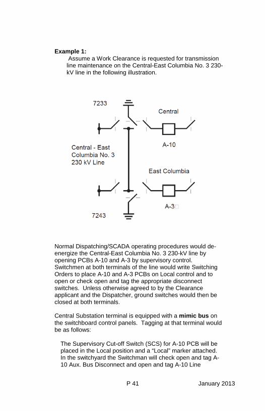
P 41 January 2013
Example 1: Assume a Work Clearance is requested for transmission line maintenance on the Central-East Columbia No. 3 230-kV line in the following illustration.
Normal Dispatching/SCADA operating procedures would de-energize the Central-East Columbia No. 3 230-kV line by opening PCBs A-10 and A-3 by supervisory control. Switchmen at both terminals of the line would write Switching Orders to place A-10 and A-3 PCBs on Local control and to open or check open and tag the appropriate disconnect switches. Unless otherwise agreed to by the Clearance applicant and the Dispatcher, ground switches would then be closed at both terminals. Central Substation terminal is equipped with a mimic bus on the switchboard control panels. Tagging at that terminal would be as follows:
The Supervisory Cut-off Switch (SCS) for A-10 PCB will be placed in the Local position and a “Local” marker attached. In the switchyard the Switchman will check open and tag A-10 Aux. Bus Disconnect and open and tag A-10 Line
P 42 January 2013
Disconnect with red Do Not Operate tags checked “See Tag on A-10 Control Panel.” In the Control House, the Switchman will tag the mimic bus A-10 Line Disconnect and A-10 Aux. Bus Disconnect with miniature red Work Clearance tags. The Switchman will fill out and place on the A-10 control panel the master red Do Not Operate tag containing all necessary information.
East Columbia Substation terminal has no mimic bus on the switchboard control panels. Tagging at that terminal would be as follows:
The SCS for A-3 PCB will be placed in the Local position and a “Local” marker attached. In the switchyard, the Switchman will check open and tag A-3 Aux. Bus Disconnect with a red Do Not Operate tag checked “See Tag on A-3 Line Disc”. The Switchman will open and tag A-3 Line Disconnect with the filled out master red Do Not Operate tag containing all necessary information.
Note that at both substations there is only one filled out master tag for the switching and tagging done at that station for this Clearance. At the Control Center, the Dispatcher will pin the Group Display Board with white pins in the isolating devices which are open and tagged as the limits of this Clearance with red pins and white disks on closed Ground Switches, and with a miniature red Work Clearance tag containing the Clearance Holder’s name and Clearance number. Example 2:
Assume a Test Clearance also requested on A-10 PCB for maintenance during the time the Central-East Columbia No. 3 230-kV line is out of service on a Work Clearance. A-10 PCB is already open and on Local control with a ‘“Local marker” attached to the SCS.
The Switchman at Central Substation would write a Switching Order to open or check open and tag the appropriate disconnect switches. In the switchyard, the Switchman will check open and tag A-10 Line Disconnect and open and tag A-10 Main Bus Disconnect
P 43 January 2013
with red Do Not Operate tags checked “See Tag on A-10 Control Panel”. In the Control House, the Switchman will tag the mimic bus A-10 Line Disconnect and A-10 Main Bus Disconnect with miniature blue Test Clearance tags. The Switchman will fill out and place on the A-10 control panel the master red Do Not Operate tag containing all necessary information. At the Control Center, the Dispatcher will pin the Group Display Board with white pins in the isolating devices which are open and tagged as the limits of this Clearance, and with a miniature blue Test Clearance tag containing the Clearance holder’s name and Clearance number. The tagging of isolating devices that are the limits of, but not the common junction point between more than one Clearance is explained in example 3.
P 44 January 2013
Example 3: Assume that the foremen of two different crews each had a Work Clearance on the same PCB shown below. The isolating devices used as the limits of both Clearances were the same. Only one Do Not Operate tag would be hung on each of the isolating One Line devices. The Do Not Operate tag would not be removed until after both Clearances were released.
The tagging of isolating devices that are the common junction point between multiple Clearances is explained in example 4.
P 45 January 2013
Example 4: One Clearance is issued on a Transformer Bank. A second Clearance is issued on the Transformer Bank PCB. The disconnect switch between the Transformer Bank and the PCB is the isolating device common to both Clearances. (Refer to the following drawing). The common disconnect switch would have two Do Not Operate tags hung on it. The other disconnect switches would each have one Do Not Operate tag hung on them. When one of the two Clearances is released, one of the two Do Not Operate tags on the common disconnect would be removed. After the other Clearance is released the remaining Do Not Operate tags would be removed.
If two Clearances are issued on the PCB and one Clearance on the Transformer Bank, two Do Not Operate tags would be hung on the common disconnect switch. The other disconnect switches would each have one Do Not Operate tag hung on them. (Refer to the following drawing). If one of the Clearances on the PCB is released first, none of the Do Not Operate tags would be removed. If the Clearance on the
P 46 January 2013
Transformer Bank was released first, one of the two Do Not Operate tags on the common disconnect and the Do Not Operate tag on the other disconnect switch associated with the Clearance on the Transformer Bank would be removed. When the last Clearance is released all remaining Do Not Operate tags would be removed.
Example 5: Assume that a Work Clearance is requested for Transformer Bank No. 1 including the Station Service transformer bank as illustrated in the following drawing. A-9 Transformer Side and Auxiliary Bus and B-2 Transformer Side and Auxiliary Bus disconnect switches will be tagged as Clearance limits with Do Not Operate tags. For the purpose of controlling energization of the equipment included within the Clearance from the alternate station service source, a Do Not Operate tag shall also be placed on the open low-voltage isolating device ACB-1 as a Clearance limit.
If work is to be performed on the low-voltage equipment included within the Clearance limits, appropriate Lockout/Tagout procedures shall be followed.
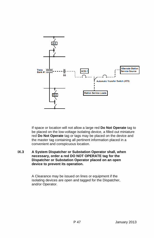
P 47 January 2013
If space or location will not allow a large red Do Not Operate tag to be placed on the low-voltage isolating device, a filled out miniature red Do Not Operate tag or tags may be placed on the device and the master tag containing all pertinent information placed in a convenient and conspicuous location.
IX.3 A System Dispatcher or Substation Operator shall, when necessary, order a red DO NOT OPERATE tag for the Dispatcher or Substation Operator placed on an open device to prevent its operation.
A Clearance may be issued on lines or equipment if the isolating devices are open and tagged for the Dispatcher, and/or Operator.
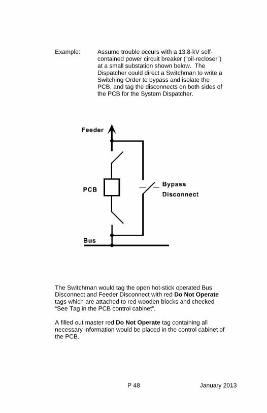
P 48 January 2013
Example: Assume trouble occurs with a 13.8-kV self-contained power circuit breaker (“oil-recloser”) at a small substation shown below. The Dispatcher could direct a Switchman to write a Switching Order to bypass and isolate the PCB, and tag the disconnects on both sides of the PCB for the System Dispatcher.
The Switchman would tag the open hot-stick operated Bus Disconnect and Feeder Disconnect with red Do Not Operate tags which are attached to red wooden blocks and checked “See Tag in the PCB control cabinet”. A filled out master red Do Not Operate tag containing all necessary information would be placed in the control cabinet of the PCB.
P 49 January 2013
IX.4 When a System Dispatcher or Substation Operator is releasing their red DO NOT OPERATE tag on an open isolating device, the System Dispatcher or Substation Operator shall make a statement similar to the following: “This is _________ and I am releasing my System Dispatcher’s or Substation Operator’s tag on ___________. There are no outstanding Clearances issued against my tag.” Isolating devices tagged with red DO NOT OPERATE tags shall not be operated until the tag has been removed by an approved Switching Order.
IX.5 A large yellow on white or miniature yellow CAUTION tag
must be placed on equipment or controls to warn about abnormal, unusual, unsafe, or hazardous conditions. The large Caution tags are pictured on page A 4. The miniature Caution tags are pictured on page A 5. Example 1:
Assume a 230-kV Transformer PCB is to be by passed, cleared, and tagged for substation maintenance. Current Transformer connections require that the Transformer Differential relays be out of service during the entire time that the Auxiliary Bus Disconnect is closed.
The Switchman will place a yellow on white Caution tag checked “See Tag on relay panel no. xx” on the control switch of the bypassed PCB denoting that an abnormal condition exists. A filled out master yellow on white Caution Tag will be placed on that relay panel on the Transformer Differential relays that are out of service.
P 50 January 2013
Example 2: Assume one PCB in a bay of a breaker-and-a-half configuration has been determined to be inadequate for line-dropping. Protective relay schemes have been modified to prevent this PCB from being the last one to open by relay operation, and tagging is deemed necessary to prevent inadvertent line dropping during routine switching.
The Switchman may be directed to place a yellow on white Caution tag on the control switch of the PCB. If, as in many newer 500-kV substations, miniature control panels are installed, a miniature yellow Caution tag will be placed on the control switch stating the precaution and the date. In a convenient location adjacent to the control panel, a filled out large master yellow on white Caution tag will be placed. At the control center, the Group Display Board(s) may be tagged with a miniature yellow Caution tag advising of the unusual operating restriction on this PCB, and the date. Example 3:
Assume that the Load-Break Disconnect (LBD) to a Section of a 230 kV grounded-wye Capacitor Group is open, cleared, and tagged for maintenance work. The other Sections of the Capacitor Group will remain in service or available for service.
Before the Clearance is issued, all automatic voltage controls on 230 kV shunt capacitors at that substation will be placed in the manual mode, and yellow on white Caution tags will be placed on the control switches of the PCBs or LBDs of all other 230 kV Capacitor Sections at that substation, stating “Notify workers to stand clear before closing this switch.” If the substation remains on Supervisory Control, the control center will also tag these controls in a similar manner.
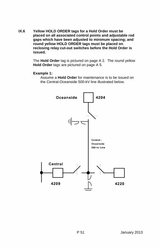
P 51 January 2013
IX.6 Yellow HOLD ORDER tags for a Hold Order must be placed on all associated control points and adjustable rod gaps which have been adjusted to minimum spacing; and round yellow HOLD ORDER tags must be placed on reclosing relay cut-out switches before the Hold Order is issued. The Hold Order tag is pictured on page A 2. The round yellow Hold Order tags are pictured on page A 5. Example 1:
Assume a Hold Order for maintenance is to be issued on the Central-Oceanside 500-kV line illustrated below.
P 52 January 2013
The Dispatcher will contact Switchmen and request the reclosing relays cut-out on PCBs 4209 and 4220 at Central Substation and on PCB 4204 at Oceanside Substation, and the reclosing relays and each PCB control switch be tagged with a Hold Order for the Dispatcher. At Central, the Switchman will place the reclosing relay cut-out switch on PCBs 4209 and 4220 to the off position and tag each with a round yellow Hold Order tag for the Dispatcher. He will also tag each PCB control switch with a yellow Hold Order tag for the Dispatcher and report to the Dispatcher. At Oceanside, the Switchman will place the reclosing relay cut-out switch on PCB 4204 to the off position and tag with a round yellow Hold Order tag for the Dispatcher. He will also tag the PCB control switch with a yellow Hold Order tag for the Dispatcher and report to the Dispatcher. If adjustable rod gaps were to be operated, the Dispatcher would direct the Switchmen at Central and Oceanside to write a Switching Order to set and tag the rod gaps at minimum spacing. At Central, the Switchman will adjust the rod gaps on the Oceanside line terminal to minimum spacing and tag with full size yellow Hold Order tags checked “See Tag on PCB 4220 controls” and attached to red wooden blocks. The yellow Hold Order tag placed on PCB 4209 controls would also be checked “See Tag on PCB 4220 controls”. The filled out yellow Hold Order tag would be placed on the control switch of PCB 4220 for the Dispatcher with the reason stating “Hot-line work, Rod gaps set to minimum spacing.” The Central Switchman would report this completed Switching Order to the Dispatcher. At Oceanside, the Switchman would adjust the rod gaps on the Central line terminal to minimum spacing and tag with full size yellow Hold Order tags checked “See Tag on PCB 4204 controls” and attached to wooden blocks. A filled out yellow Hold Order tag would be placed on the control switch of PCB 4204 for the Dispatcher with the Reason stating “Hot-line work, rod gaps set to minimum spacing.” The Oceanside Switchman will report this completed Switching Order to the Dispatcher.
P 53 January 2013
The Dispatcher tags the supervisory control points for the PCBs with a Hold Order tag. The Dispatcher issues the Hold Order to the workman and then tags the line or facility on the Group Display Board with a round yellow Hold Order tag for the workman. Tagging for a Hold Order at a substation where the reclosing relay can be cut out from a Control Center. Example 2:
Referring to the drawing, assume a Hold Order is to be issued for tree removal on the Central - Oceanside 500 kV line illustrated above.
At Central, the Switchman will place the reclosing relay cut-out switch on PCBs 4209 and 4220 to the off position and tag each with a round yellow Hold Order tag for the Dispatcher. The Switchman will also tag each PCB control switch with yellow Hold Order tag for the Dispatcher and report to the Dispatcher. At Oceanside Substation, the Dispatcher would initiate via a single point selection from the SCADA display screen and initiate a command to disable the reclosing relay and the local close bus to PCB 4204. The Dispatcher will receive a change of status indication on the display screen confirming that the command was received and completed. At Oceanside, an amber lamp next to the PCB control switch will be illuminated indicating the reclosing relay is disabled. This will constitute the Hold Order tag for the Dispatcher at Oceanside. Additionally, the close bus indication lamp to PCB 4204 at Oceanside will not be illuminated indicating that it is disabled.
IX.7 A white Work Permit tag shall be placed on:
A. Affected equipment or circuits when a Work Permit is
issued for work at locations other than microwave sites.
B. Affected equipment or circuits at microwave sites
when the work will not be completed before the Worker leaves the worksite.
C. Isolating devices which have been opened to facilitate
work not requiring a Clearance or a Hold Order (see example 2).
P 54 January 2013
The large Work Permit tags are pictured on page A 3. The miniature Work Permit tags are pictured on page A 5.
Example 1:
Assume work is to be done on the Microwave Transfer Trip (MWTT) relaying of a three terminal 230-kV line.
Tone-Test switches (TTS) at all three terminals will be turned to the “off” position and tagged with a white Work Permit tag for John Doe. PCB control switches at each terminal will be tagged with a white Work Permit tag checked ‘“See Tag on relay panel no. XX”.
Example 2:
Assume work is to be done on the air system of a 500-kV air-blast PCB and it has been determined that a Clearance is not required.
The PCB will be isolated from the power system by open isolating devices. In the switchyard, the open disconnect switches will be tagged with a white Work Permit tag checked “See Tag on PCB XXXX control switch”. The control switch for the PCB will be tagged with a filled out master white Work Permit tag for John Doe. At control centers, the Group Display Boards will be tagged with miniature white Work Permit tags in both Example 1 and 2.
Example 3:
Assume work is to be done on power system equipment at a Microwave Site; and that the work is completed before the workman leaves the worksite.
No Work Permit tag will be required.
Example 4:
Assume work is to be done on power system equipment at a Microwave Site; and that the work is not completed before the Worker leaves the worksite.
The equipment will be tagged with a Work Permit tag for the Worker.
P 55 January 2013
D. Isolating devices which have been opened to facilitate work on low voltage circuits, equipment and energy storage systems (see example 5 below).
Example 5:
Assume a 230 kV PCB is bypassed over a Bus Tie PCB and a Work Clearance has been issued for trouble on the compressor system.
During the course of work a maintenance worker decided the compressor bus cable is needed in order to make repairs and requests the compressor bus cable de-energized. Permission from the appropriate System Dispatcher is obtained and the compressor bus cable supply ACB is cut out and tagged with a Work Permit tag for the requestor. A Work Permit is then issued to the requestor. Any Authorized Employee(s) who are to perform work involving the compressor bus cable would follow APM Rule L-3 and BPA Work Standard Section VIII - Lockout/Tagout.
P 56 January 2013
IX.8 Red DO NOT OPERATE tags may be placed on low voltage isolating devices to prevent their operation.
The Do Not Operate tags are pictured on page A 2. The miniature Do Not Operate tags are pictured on page A 5. Example:
Assume a compressor bus cable is cut out on a Work Permit for repairs in one bay of a Breaker and a Half scheme. The Operator may place a filled out red Do Not Operate tag for the Operator on the supply ACB in addition to the Work Permit tag to control its operation due to branch circuits. If more than one source of power must be opened, the other tags will be checked “See Tag on (location of master tag).”
If space or location will not allow a large red Do Not Operate tag to be placed, a filled out miniature red Do Not Operate tag or tags may be placed and the master tag containing all pertinent information placed in a convenient and conspicuous location.
IX.9 Blue ELECTRICAL TEST MARKERS must be placed on all
high voltage conductors attached to a piece of equipment being tested under a Work Clearance as close to the point of separation as possible.
The Electrical Test Marker is pictured on page A 4.
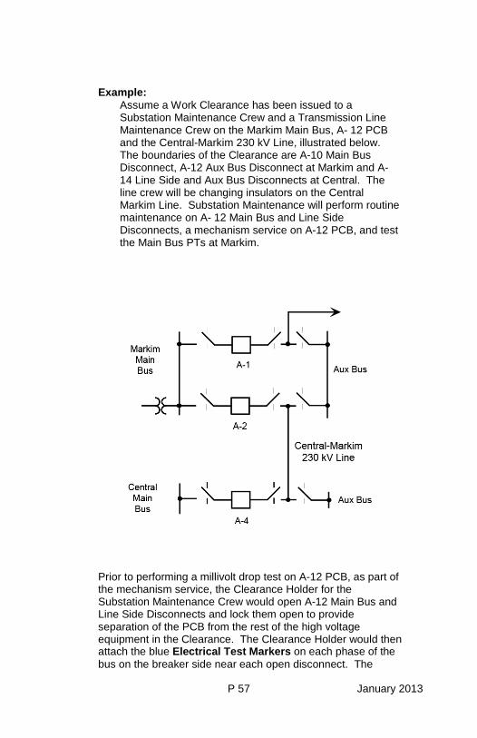
P 57 January 2013
Example: Assume a Work Clearance has been issued to a Substation Maintenance Crew and a Transmission Line Maintenance Crew on the Markim Main Bus, A- 12 PCB and the Central-Markim 230 kV Line, illustrated below. The boundaries of the Clearance are A-10 Main Bus Disconnect, A-12 Aux Bus Disconnect at Markim and A- 14 Line Side and Aux Bus Disconnects at Central. The line crew will be changing insulators on the Central Markim Line. Substation Maintenance will perform routine maintenance on A- 12 Main Bus and Line Side Disconnects, a mechanism service on A-12 PCB, and test the Main Bus PTs at Markim.
Prior to performing a millivolt drop test on A-12 PCB, as part of the mechanism service, the Clearance Holder for the Substation Maintenance Crew would open A-12 Main Bus and Line Side Disconnects and lock them open to provide separation of the PCB from the rest of the high voltage equipment in the Clearance. The Clearance Holder would then attach the blue Electrical Test Markers on each phase of the bus on the breaker side near each open disconnect. The
P 58 January 2013
Clearance Holder would then notify any other Clearance Holders in the immediate area that electrical tests will be performed on A-12 PCB. The Clearance Holder would then perform or directly supervise the millivolt drop test. Once the test was complete, the Clearance Holder would then remove all blue Electrical Test Markers and notify any other Clearance Holders the immediate area that the electrical tests on A-12 PCB are complete. Once the tests are complete and the blue Electrical Test Markers are removed, A-12 Main Bus and Line Side Disconnects may be operated at the will of the Clearance Holder. Prior to performing electrical tests on the Main Bus PTs, the Clearance Holder would direct the crew to remove or disconnect and tie back the conductor from the Main Bus to each PT which would be tested. The Clearance Holder would then attach the blue Electrical Test Marker to the top of each PT to be tested. The Clearance Holder would then notify any other Clearance Holders in the immediate area that electrical tests will be performed on the Main Bus PTs. The Clearance Holder would then perform or directly supervise the electrical tests. Once the tests are complete, the Clearance Holder would remove the blue Electrical Test Markers from each of the PTs which were tested and notify any other Clearance Holders in the immediate area that electrical tests on the PTs are complete. Installation of the conductor from the Main Bus to the PTs could then be done at the will of the Clearance Holder. The intent of the placement of the blue Electrical Test Markers is to visually outline the electrical equipment which is being tested under a Work Clearance. While the methods outlined above are the prescribed way of placing the blue Electrical Test Markers, it is realized that the numerous conditions of separating equipment may produce a situation where strict adherence to the prescribed method of hanging the blue Electrical Test Markers may interfere with the electrical tests being performed. In those instances, the Clearance Holder should place the blue Electrical Test Markers in a way which will most closely follow the prescribed rules and the intent of visually outlining the equipment being tested.
CHAPTER 2
P iii January 2013
United States Department of Energy Bonneville Power Administration
System Operations
Operating Bulletin NO. 2 Accident Prevention Rule S-6
SWITCHING & CLEARANCE PROCEDURE
TABLE OF CONTENTS Page V. CLEARANCES P 59
V.1 Work and Test Clearances P 59
V.5 Issuing and Receiving Clearances P 60
V.10 Releasing Clearances P 63 VI. HOLD ORDERS P 64
VI.3 Issuing and Receiving Hold Orders P 64 VII. WORK PERMITS P 65

CHAPTER 2
P 59 January 2013
V. CLEARANCES V.1 WORK and TEST CLEARANCES
A. There are two types of Clearances and the activity
determines the type of Clearance needed.
(1) A WORK CLEARANCE provides protection when work is to be performed on de-energized high voltage lines or equipment. Electrical tests may be performed on equipment included in a Work Clearance if:
(a) The high voltage equipment is contained in a
substation. (b) The equipment is under the physical control of
the Clearance Holder. (c) AND the equipment is separated from the rest of
the de-energized high voltage equipment in the Clearance by means sufficient to positively prevent the test voltages and/or currents from entering the remainder of the equipment protected by the Clearance.
(2) A TEST CLEARANCE provides protection when
electrical tests are to be performed on high voltage equipment and the conditions required for application of electrical tests under a Work Clearance in A., (1), (a), (b), or (c) cannot be met.
B. More than one WORK CLEARANCE may be issued on the
same line or equipment to multiple crews. C. Under the following circumstances more than one WORK
CLEARANCE may be issued to members of the same crew for work on the same equipment:
P 60 January 2013
(1) If the expected duration of the work is one month or more, a second clearance holder may be requested at the time the outage request is made.
(2) Transformer dry-outs (or similar type work) where
work occurs around the clock or during significantly extended workdays where one Clearance Holder must relieve another Clearance Holder because of the on-going nature of the work. A second and, if necessary, third Clearance Holder could be requested at the time the outage request is made for this type of work.
D. Only one TEST CLEARANCE may be issued on the same
line or equipment.
V.5 ISSUING AND RECEIVING CLEARANCES
A. All Clearances on the BPA power system shall be issued by a System Dispatcher or Substation Operator. The System Dispatcher or Substation Operator may delegate the authority to issue Clearances to a Switchman.
The Dispatcher or Operator having jurisdiction over the facilities which are cleared is responsible for issuance of the Clearance.
(1) A Dispatcher’s Clearance is issued by or with the
permission of the Dispatcher who has jurisdiction over the facilities which are cleared.
(2) A Station Clearance is issued by an Operator who has
jurisdiction over the facilities which are cleared.
B. When more than one Clearance is issued or is to be issued on a transmission line or associated terminal equipment, each Clearance Holder shall be given the names of the other Clearance holders and advised of the type of work that each Clearance Holder will be
CHAPTER 2
P 61 January 2013
performing. All Clearance holders shall be informed of this at the time of receiving their Clearance. Existing Clearance holders shall be advised of additional Clearance requests prior to the issuance of any new Clearance(s).
C. In emergencies when no communications are available,
Switchmen may do necessary switching and tagging and issue Clearances to themselves.
D. Clearances will be issued to employees and contractors
only for whom a Clearance Certification is on file with the Dispatchers and to Dispatchers and qualified personnel of other utilities or customers.
When issuing a Clearance, the Dispatcher or Operator shall state clearly to the person receiving the Clearance:
(1) The name of the person receiving the Clearance. (2) The exact name of the line or equipment at the job site
that is cleared and tagged. (3) The type of Clearance being issued. (4) The Clearance number. (5) The status of available ground switches.
Example: “John Doe, the Central-East Columbia
No. 3 230-kV line is cleared and tagged for you on Work Clearance No. D-4567W, and ground switches at Central and East Columbia are closed.”
P 62 January 2013
When receiving a Clearance, the Clearance Holder shall repeat back to the Dispatcher or Operator:
(1) The name of the person receiving the Clearance. (2) The exact name of the line or equipment at the job site
that is cleared and tagged. (3) The type of Clearance being received. (4) The Clearance number. (5) The status of available ground switches. Example: “This is John Doe and I understand that the
Central-East Columbia l No. 3 230-kV line is cleared and tagged for me on Work Clearance No. D-4567W, and ground switches at Central and East Columbia are closed.”
E. When a Clearance is received on equipment in a
substation, it shall be the Clearance Holder’s responsibility to go with the Switchman to:
(1) Point out the specific limits of the Clearance. (2) Point out which facilities are included in the
Clearance. (3) Point out specific hazards in the work area presented
by energized circuits and equipment. It shall be the Switchman’s responsibility to assure
that the above information the Clearance Holder gives is correct.
If the Switchman is not present when the Clearance is
issued, the Clearance Holder will assure that his/her
CHAPTER 2
P 63 January 2013
understanding of the above information is correct by touring the Clearance site and checking the tagged isolating devices before any work associated with the Clearance begins.
Other persons present who will work under the Clearance
should, where practical, be included in the tours as an aid to fulfilling the Clearance Holder’s responsibilities described in V.9.
F. When foreign crews work on lines or equipment under
BPA jurisdiction, Clearances will be issued in accordance with BPA rules and procedures.
G. When BPA crews work on lines or equipment under
foreign jurisdiction, they will receive Clearances in accordance with the foreign utility’s rules and procedures.
H . When BPA crews require a Clearance on lines or
equipment under a foreign utility’s jurisdiction for proximity work on a BPA project, the BPA Dispatcher will issue the Clearance, except in those cases where the foreign utility’s rules and procedures dictate that the utility will issue the Clearance.
V.10 RELEASING CLEARANCES
A. All Clearances must be promptly released when the work or test is completed.
B. The System Dispatcher may delegate authority to a
Switchman to accept the release of Dispatcher’s numbered Clearances. Clearances held by Contractors shall be released only to the System Dispatcher.
P 64 January 2013
VI. HOLD ORDERS
VI.3 ISSUING AND RECEIVING HOLD ORDERS
The Dispatcher shall order automatic reclosing cut-out and tagged, and all other control points tagged for a Hold Order. When all procedures have been completed for the provisions of the Hold Order, the Dispatcher shall issue the Hold Order to the worker and the hot-line maintenance or proximity work can proceed.
A. All Hold Orders on the BPA power system shall be issued
by a System Dispatcher. Authority to issue Hold Orders may be delegated to a Substation Operator.
When issuing a Hold Order, the Dispatcher or Operator shall state clearly to the person receiving the Hold Order:
(1) The name of the person receiving the Hold Order. (2) The exact name of the line or equipment included in
the Hold Order.
Example: “John Doe, you now have a Hold Order on the Central-East Columbia No. 2 230-kV line.”
B. Hold Orders will be issued to employees and contractors
only for whom a Clearance Certification is on file with the Dispatchers, and to Dispatchers and qualified personnel of other utilities or customers.
When receiving a Hold Order, the recipient of the Hold Order shall repeat back to the Dispatcher or Substation Operator:
(1) The name of the person receiving the Hold Order.
CHAPTER 2
P 65 January 2013
(2) The exact name of the line or equipment included in the Hold Order.
Example: “This is John Doe, and I now have a Hold Order on
the Central-East Columbia No. 2 230-kV line.”
The Dispatcher or Operator and the recipient of the Hold Order shall confirm the location of the crew and the communication which will be available for the duration of the Hold Order.
C. When foreign crews require a Hold Order for work on lines
or equipment under BPA jurisdiction, the Hold Order will be issued in accordance with BPA rules and procedures.
D. When BPA crews require a Hold Order for work on lines or
equipment under foreign jurisdiction, they will receive Hold Orders in accordance with the foreign utility’s rules and procedures.
E. When BPA crews require Hold Orders on lines or
equipment under a foreign utility’s jurisdiction for proximity work on a BPA project, the BPA Dispatcher will issue the Hold Order, except in those cases where the foreign utility’s rules and procedures dictate that the utility will issue the Hold Order.
VII. WORK PERMITS
VII.6 Work Permits will be issued to qualified employees, as
determined by their supervisors and qualified persons of other utilities.

A 1 March 2011
X. COLOR ADDENDUM
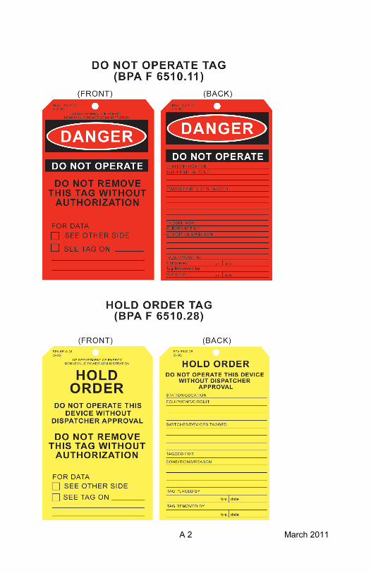
A 2 March 2011
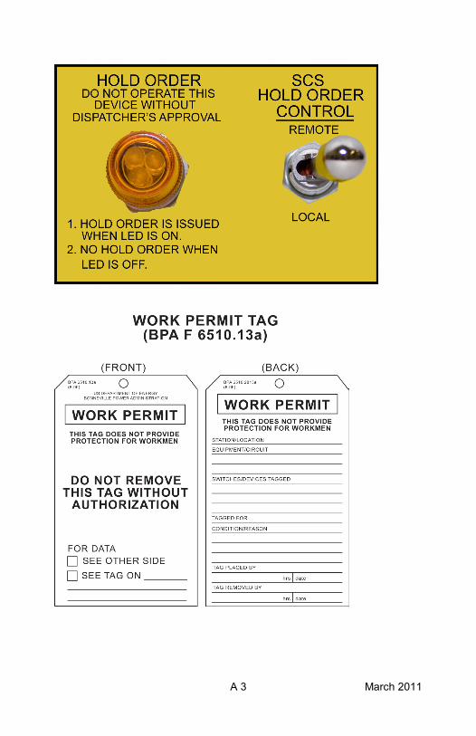
A 3 March 2011
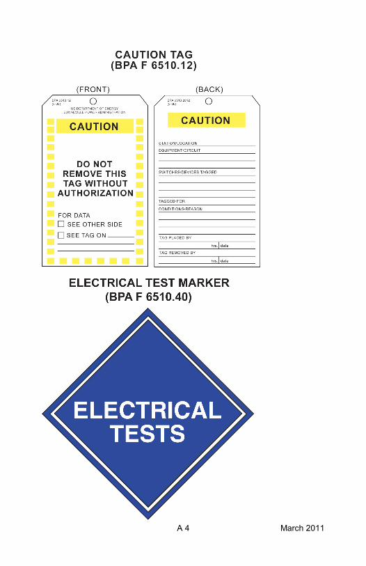
A 4 March 2011
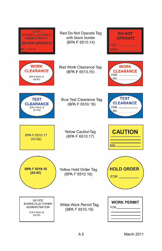
A 5 March 2011
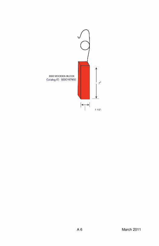
A 6 March 2011
D 1 January 2013
GLOSSARY OF SPECIAL TERMS AND PHRASES
Adjustable Rod Gap
Assurance of no backfeed
At the Job Site
Authorized Employee
Bonding
A switching device on 500 kV line terminals. Reducing the rod gap spacing provides added protection for workmen while PERFORMING LIVE-LINE WORK.
The assurance given by a utility that at a specific point of interconnection they have no means of backfeeding that circuit, or if they have an alternative source of power, that source is isolated from the interconnection and the isolation point will not be closed without the permission from the BPA Dispatcher. “At the Job Site” means at the location where the work is being performed. The holder of a Clearance or Hold Order may place or respond to telephone or radio calls, perform paperwork incidental to the job at hand, use available restroom facilities, or perform other minor tasks incidental to the work and still be considered “At the Job Site”.
For Clearances and Hold Orders issued for work on transmission lines where the work requires workers at more than one location, the holder of the Clearance or Hold Order is considered to be “At the Job Site” when with a group of workers or traveling between groups of workers, provided that radio or cell phone contact can be maintained with the Dispatcher and all groups of workers. A person who locks out or tags out machines or equipment to perform the servicing or maintenance on that machine or equipment.
The interconnection of conductive parts designed to maintain a common electrical potential.
D 2 January 2013
One who is capable of identifying existing and predictable hazards in the surroundings, or working conditions which are unsanitary, hazardous, or dangerous to employees, and who has authorization to take prompt corrective measures to eliminate them.
Assurance given to a worker by a System Dispatcher or Substation Operator that (1) specified power system equipment or a transmission line is isolated from the power system, and (2) it will not be ordered energized from the power system until that worker reports the crew in the clear and the equipment or line ready for service and the Clearance is released. Equipment controls that automatically or can be remotely closed to energize a high voltage circuit. Isolating devices are not considered control points.
Contract journeyman, electrical apprentice, journeyman in training, temporary electrical worker.
As applied in Chapter One: Is any BPA employee represented by the Columbia Power Trades Council.
As applied in Chapter Two: Is any BPAemployee not represented by the Columbia Power Trades Council.
Any source of electrical, mechanical, hydraulic, pneumatic, chemical, thermal or other energy.
The use of a device or procedure that ensures any potentially hazardous stored or residual energy be relieved, disconnected, restrained and otherwise rendered safe.
The large one-line diagram board of the power system installed in Control Centers.
Competent Person
Clearance (Work or Test)
Control Point
Electrical Worker
Employee
Energy Source
Energy Source Control
Group Display Board
D 3 January 2013
Assurance given to a worker by a System Dispatcher or Substation Operator that if specified power system equipment or a transmission line is de-energized, it will not be ordered energized until that worker reports the crew in the clear.
Electrical apparatus used to isolate power system lines and equipment from a source of energization. High-voltage isolating devices include disconnect switches, hot-stick links, removable bus links, or transmission line jumpers, which provide an air-gap of approved design for the circuit, or gas-insulated disconnect switches which are contained within an SF6 gas reservoir operating at or above normal gas density. Low-voltage isolating devices are used to isolate high-voltage equipment from potential back feed through a source of low-voltage energization. These devices include ACBs, disconnect switches, removable fuses, or other positive isolating means*. Low-voltage isolating devices do not include automatic transfer switches and non-lockable manual transfer switches.
* Work Standard BPA-WS-8-1, Lockout/Tagout defines other positive isolating means by example: removing valve handles, lifting, taping leads from the load side of the breaker, removing plug-in type breakers from the panel, etc.
Methods of operating an isolating device have been disabled and a lock(s) placed on the device providing mechanical restraint on the operating linkage to prevent inadvertent closing by either a personnel action or a natural event.
Manufacturer designed means used to assure positive mechanical restraint of the isolating device to prevent inadvertent closing by a natural event.
Hold Order
Isolating Device
Isolating Device, Non-operative
Isolating Device, Restrained
D 4 January 2013
Boundaries of a Clearance designated by open and properly tagged isolating devices.
A permanent record maintained at each substation and control center.
High-voltage power system equipment is considered “normally energized” if it is energized or could be energized by closing an isolating device.
Work being performed near normally energized high-voltage facilities where inadvertent movement of personnel or equipment could result in violating the applicable Minimum Approach Distance.
All mechanical, electrical, or electronic equipment or circuits required for the operation of a high-voltage power system.
An employee, who by training and experience demonstrates knowledge and proficiency in climbing techniques, equipment, rescue methods, principles, and is knowledgeable of the hazards associated with climbing.
BPA employee who has an Electrical Worker Permit as defined in Rule A-1, Access to BPA Energized Facilities. Only Qualified Electrical Employees are authorized to wear yellow hard hats.
Any person who, by experience or training is familiar with the work to be performed and the hazards involved and is, in the judgment of the Dispatcher, qualified to do the task.
Positive means used to assure restraint of the isolating device or disconnect blades so that the disconnect blades can not fall closed.
Limits of a Clearance
Log
Normally Energized
Proximity Work
Power System Equipment
Qualified Climber
Qualified Electrical Employee
Qualified EmployeeQualified Person
Restrained
D 5 January 2013
Shorting(Short Circuiting)
Switchman
Standing Operating Orders
Switching Order
Test Voltages
Terminal Clearance
The process that establishes a metallic connection between two or more points in an electrical circuit that has the capacity to conduct any anticipated current.
Any person who, by experience or training, is familiar with the operation to be performed and the hazards involved and is, in the judgment of the dispatcher, qualified to perform the assigned switching.
Pre-approved Dispatching Orders which permit restoration of the transmission system and service to customers with minimum delay after trouble occurs. On file at each substation and control center, they cover trouble situations which can reasonably be expected at a substation while in its normal Operating mode.
A step-by-step plan to perform switching operations in a specific sequence.
Electrical voltages and currents applied to power system facilities with testing equipment for the purpose of calibration, information, or testing. Power system voltages are not considered “test voltages”.
A Terminal Clearance is a formal assurance of isolation of a Local Terminal or Terminals* of an interconnecting circuit provided by the Local System Dispatcher** to a requesting Dispatcher. The Terminal Clearance assures the requesting dispatcher that the terminal or source is open, properly cleared and tagged according to local procedures, and that it will not be energized until a release is given by the Dispatcher receiving the Terminal Clearance.
D 6 January 2013
A Terminal Hold is a formal assurance of non-reclosure at the Local Terminal or Terminals* of an inter-connecting circuit provided by the Local System Dispatcher** to a requesting Dispatcher. The Terminal Hold assures the requesting Dispatcher that the terminal or source on “Hold” has sufficient relays in service to provide protection in the event of a fault; and, once tripped out of service, will not be energized, automatically or manually until the Dispatcher receiving the Terminal Hold has advised that all personnel and materials are in the clear and it is safe to energize.
Refers to electrical equipment that incorporate metal enclosures, barriers, and insulated cables and connectors typically used to serve residential and light industrial loads. At BPA URD equipment is used to provide station service electric power in substations and to non-electric plant (NEP) facilities. Typical operating voltages for URD equipment range from 120/240 VAC to 34.5k VAC. URD equipment may also be referred to as “Pad–Mount” or “Metal Enclosed” which are also industry accepted terms.
Grounds that may be used for protection against electric shock in conjunction with the grounding of URD equipment or cables. URD grounds are fitted with standardized insulated connectors (elbow) on one end and are designed to connect to the insulated bushings of metal enclosed URD transformers or switches. URD grounds have limited fault current carrying capacity due to limitations in the insulated elbow connectors and not necessarily the cable itself. URD grounds are limited to 10,000 amps (I2t) for 10 cycles; 5,800 amps for 30 cycles, and 3,500 amps for 3 seconds.
Terminal Hold
Underground Residential Distribution (URD):
URD Grounds:
D 7 January 2013
Permission granted to work on power system equipment, equipment deenergized for work near suspect equipment or induced voltage reduction when the work does not require a Clearance or Hold Order. A Work Permit does not provide electrical contact protection for personnel, or permit the violation of applicable Minimum Approach Distances.
*A Local Terminal is a terminal of an interconnecting circuit under the authority of the Local System Dispatcher.
**The Local System Dispatcher is the Dispatcher who has the authority over a Local Terminal or Terminals of an interconnecting circuit.
Work Permit
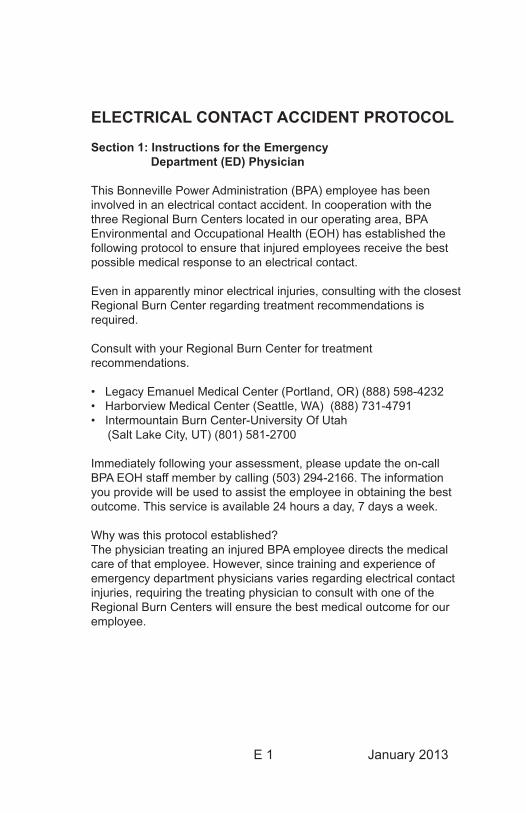
E 1 January 2013
ELECTRICAL CONTACT ACCIDENT PROTOCOL
Section 1: Instructions for the Emergency Department (ED) Physician
This Bonneville Power Administration (BPA) employee has been involved in an electrical contact accident. In cooperation with the three Regional Burn Centers located in our operating area, BPA Environmental and Occupational Health (EOH) has established the following protocol to ensure that injured employees receive the best possible medical response to an electrical contact.
Even in apparently minor electrical injuries, consulting with the closest Regional Burn Center regarding treatment recommendations is required.
Consult with your Regional Burn Center for treatment recommendations.
• Legacy Emanuel Medical Center (Portland, OR) (888) 598-4232• Harborview Medical Center (Seattle, WA) (888) 731-4791• Intermountain Burn Center-University Of Utah (Salt Lake City, UT) (801) 581-2700
Immediately following your assessment, please update the on-call BPA EOH staff member by calling (503) 294-2166. The information you provide will be used to assist the employee in obtaining the best outcome. This service is available 24 hours a day, 7 days a week.
Why was this protocol established?The physician treating an injured BPA employee directs the medical care of that employee. However, since training and experience of emergency department physicians varies regarding electrical contact injuries, requiring the treating physician to consult with one of the Regional Burn Centers will ensure the best medical outcome for our employee.

E 2 January 2013
This Page Intentionally Left Blank
E 3 January 2013
Section 2: Employee Guidelines
1. An Electrical Contact Accident is defined as any current flow through or across the employee’s body or if any of the following is true.
The contact resulted: a. In burns or wounds; b. In interrupted or impaired breathing;
c. In the Employee not able to let go of a circuit or equipment;
d. In any neurological problems, including but not limited to tremors, shaking, numbness, difficulty balancing, difficulty walking, confusion, disorientation, speech difficulties, vision problems, or bladder problems, or headache;
e. In pain lasting greater than 5 minutes.
2. Following any electrical contact injury immediately call 911 and initiate First Aid. Do not move the injured employee, unless the accident occurred in a remote location.
Remote Location Instructionsa. If the injury occurred in a remote location follow the BPA Safety and Health Program Handbook, Remote Location Emergency Medical Response, Section B, Chapter 11.
i. Notify the BPA Dispatcher and inform them of the location (including the county) and nature of the accident.
ii. Field crews will notify the local 911 center, Emergency Medical System (EMS), directly if communications are available. Supervisors shall ensure that all employees are informed of procedures for summoning emergency medical services at their work locations. Dispatch is to be notified as soon as possible.
iii. While awaiting medical response, employees should stabilize and care for the injured (to the extent of their First Aid training). Do not attempt to move the injured person unless they are at risk of further injury from hazards at the scene or directed to do so by medical personnel.
E 4 January 2013
iv. Assist EMS personnel in arriving at the accident scene. If available, a crewmember may be sent to meet EMS at a main road crossing, intersection or landmark to have medical personnel follow them to the accident scene.
3. On arrival at the emergency department, provide a copy of Section 1, Instructions to Emergency Department Physician, to the medical staff.
4. As soon as the injured employee is in the care of the emergency department personnel, immediately contact the BPA EOH staff by calling the BPA EOH answering service at (503) 294-2166.
What to do if you are uncertain about an employee’s injury?If there has been an electrical contact or suspected electrical contact, but it is not evident that the employee requires medical evaluation, immediately call the BPA EOH answering service at (503) 294-2166.
The answering service will contact the on-call BPA EOH staff member. This medical professional will immediately triage the situation and determine if further medical evaluation is required. This service is available 24 hours a day, 7 days a week.
Section 3 Return to Duty
Employees involved in an electrical contact injury must be evaluated by a physician with specialized training and experience treating burns prior to returning to duty. BPA EOH will arrange for this evaluation.
Possible Signs and Symptoms Requiring Additional Medical EvaluationThe effects of an electrical contact injury may manifest after an employee has been returned to duty. Managers and supervisors observing any behaviors or impairment that cause them to question the employee’s safety shall direct the employee away from safety sensitive work and contact BPA EOH immediately.
These signs and symptoms may include, but are not limited to, inability to concentrate, forgetfulness, inability to follow instructions, threatening behavior, unsteady gait, decreased ability to balance, and trembling.
F� January20�3
Accident / Injury Protocol
In the event of a serious accident:(Involves loss of consciousness, electrical contact, severe burns, heart attack, death, life-threatening injury or injury to 3 or more persons)
• Summonlocalemergencymedicalassistancebycalling9��.Ifnophonecoverage,contactdispatchcenter through the VHF radio. Provide first aid if possible
• IfpossibleanotherBPAemployeeshouldaccompanytheinjuredemployeetothehospitaltoactasadvocatefortheemployeetofacilitatepaperworkandconveytheclaiminformationonthiscard.
• Theimmediategroupshouldstanddownandstopwork.Securethescenefromchangeuntilreleasedby the Safety Office. Management should collect statementsofthecrew/witnessesassoonaspractical.
• Notify your first line supervisors of the incident and follow-upwiththerequiredformsforreportinginjuryaccidents.
• Contact the Safety Office at (360)418-2397. After-hours, contact the System Dispatcher at (800)392-0816.
Reporting process for all injuries and occupational illnesses:
• Notify your first line supervisors of the incident and follow-upwiththerequiredformsforreportinginjuryaccidents.
• Contact the Safety Office (360)418-2397. After-hours, contact the System Dispatcher at (800)392-0816.
F2 January20�3
• CompletetheCA-�andsubmittosupervisor.SupervisorwillsubmitcompletedformtotheOWCPCase Manager.
• Complete the employee portion of the 5480.01e, IndividualAccident/IncidentReportandsubmittoyoursupervisor.Supervisorwillsubmitthecompletedreportto the local safety manager within 6 days of incident.
• ReturntoworkassoonasphysicallyableandprovidemedicalevidencetosupervisorsandOWCPcasemanagerifdisabledforwork.
For further information and instructions on the Individual Accident / Incident Report , contact your local safety manager or the main safety office at (360) 418-2397.
For further information and instructions for the OWCP and billing process, contact the OWCP Case Manager at (503) 230-3320 or HR Help at (503) 230-3230.
Additional reporting information is also located on BPA’s Safety web site under accident reporting.
Information for Medical Facility:BPA is a Federal government agency & self-insured for work-related injuries. Bills for medical treatment must include a Case number. Bills must be submitted on a HICF 1500To: OWCP, DOL; PO Box 8300; London, KY 40742-8300
Bills must contain yourACS provider numberFor questions call OWCP at (866)335-8319 orBPA OWCP Case Manager at (503)230-3320
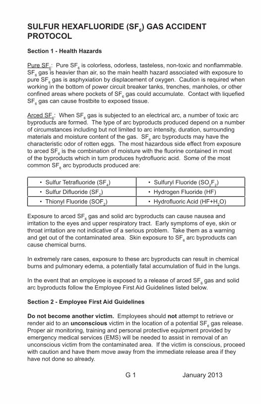
G� January20�3
SULFUR HEXAFLUORIDE (SF6) GAS ACCIDENT PROTOCOL
Section 1 - Health Hazards
PureSF6:PureSF6 is colorless, odorless, tasteless, non-toxic and nonflammable. SF6 gas is heavier than air, so the main health hazard associated with exposure to pure SF6 gas is asphyxiation by displacement of oxygen. Caution is required when working in the bottom of power circuit breaker tanks, trenches, manholes, or other confined areas where pockets of SF6 gas could accumulate. Contact with liquefied SF6 gas can cause frostbite to exposed tissue.
ArcedSF6:WhenSF6 gas is subjected to an electrical arc, a number of toxic arc byproducts are formed. The type of arc byproducts produced depend on a number of circumstances including but not limited to arc intensity, duration, surrounding materials and moisture content of the gas. SF6 arc byproducts may have the characteristic odor of rotten eggs. The most hazardous side effect from exposure toarcedSF6 is the combination of moisture with the fluorine contained in most of the byproducts which in turn produces hydrofluoric acid. Some of the most common SF6 arc byproducts produced are:
• Sulfur Tetrafluoride (SF4) • Sulfuryl Fluoride (SO2F2)• Sulfur Difluoride (SF2) • Hydrogen Fluoride (HF)• Thionyl Fluoride (SOF2) • Hydrofluoric Acid (HF+H2O)
Exposure to arced SF6 gas and solid arc byproducts can cause nausea and irritation to the eyes and upper respiratory tract. Early symptoms of eye, skin or throat irritation are not indicative of a serious problem. Take them as a warning and get out of the contaminated area. Skin exposure to SF6 arc byproducts can cause chemical burns.
In extremely rare cases, exposure to these arc byproducts can result in chemical burns and pulmonary edema, a potentially fatal accumulation of fluid in the lungs.
In the event that an employee is exposed to a release of arced SF6gasandsolidarc byproducts follow the Employee First Aid Guidelines listed below.
Section 2 - Employee First Aid Guidelines
Do not become another victim. Employees should not attempt to retrieve or renderaidtoanunconscious victim in the location of a potential SF6 gas release. Proper air monitoring, training and personal protective equipment provided by emergency medical services (EMS) will be needed to assist in removal of an unconscious victim from the contaminated area. If the victim is conscious, proceed with caution and have them move away from the immediate release area if they have not done so already.
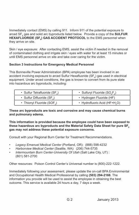
G2 January20�3
Immediately contact (EMS) by calling 911. Inform 911 of the potential exposure to arcedSF6 gas and solid arc byproducts listed below. Provide a copy of the SULFUR HEXAFLUORIDE (SF6) GAS ACCIDENT PROTOCOL to the EMS personnel when they arrive on site.
Skin / eye exposure: After contacting EMS, assist the victim if needed in the removal of contaminated clothing and irrigate skin / eyes with water for at least 15 minutes or until EMS personnel arrive on site and take over caring for the victim.
Section 3 Instructions for Emergency Medical Personnel
This Bonneville Power Administration (BPA) employee has been involved in an accident involving exposure to arced Sulfur Hexafluoride (SF6)gasusedinelectricalequipment. Under arced conditions, the gas is known to convert from its pure state into hazardous arc byproducts, including:
• Sulfur Tetrafluoride (SF4) • Sulfuryl Fluoride (SO2F2)• Sulfur Difluoride (SF2) • Hydrogen Fluoride (HF)• Thionyl Fluoride (SOF2) • Hydrofluoric Acid (HF+H2O)
These arc byproducts are toxic and corrosive and may cause chemical burns and pulmonary edema.
This information is provided because the employee could have been exposed to these hazardous arc byproducts and the Material Safety Data Sheet for pure SF6 gas may not address these potential exposure concerns.
Consult with your Regional Burn Center for Treatment Recommendations.
• Legacy Emanuel Medical Center (Portland, OR): (888) 598-4232• Harborview Medical Center (Seattle, WA): (206) 744-5735• Intermountain Burn Center-University Of Utah (Salt Lake City, UT) : (801) 581-2700
Other resources: Poison Control Center’s Universal number is (800)-222-1222.
Immediately following your assessment, please update the on-call BPA Environmental and Occupational Health Medical Professional by calling (503) 294-2166. The information you provide will be used to assist the employee in obtaining the best outcome. This service is available 24 hours a day, 7 days a week.
Bonneville Power AdministrationDOE/BP-I-1209 • January 2013
If it’s not grounded,IT’S NOT DEAD.
BPA Safety Motto
No job is so important and no service so urgent that we cannot take time to perform our work safely.
Recommended