Air Circuit Breaker (ACB)

Compact size, wide range & high breaking capacity1
630A to 4000A available in only 3 frame sizes2
First frame available upto 2000A & Modular construction for pole unit3
Common height, depth and panel door cutout4

10
Air Circuit Breaker
Operating Mechanism
It is of stored energy type, which operates using pre-charged springs. The springs are charged manually with the help of charging handle or with the help of charging motor, if provided. The same operating mechanism is used for the entire range. The mechanism has been developed using less number of parts resulting in more reliability, longer mechanical life and requiring less maintenance.
Contact Mechanism Conductor Unit is of modular design. Each pole consists of Main and Arcing contacts which are housed in the moulded housing The contacts are made from sintered silver alloy for reliability, longer life and anti-weld properties. The construction of the contact is such that arcing contact closes before and opens later than the main contact, this substantially reduces erosion of main contact under normal and short circuit conditions.The current transformer is placed inside the pole unit around the lower terminal.
Arc ChutesThese are provided for quenching the arc. Arc chute comprises of grid
Cradle
Control Terminals
Arc Chute
Over Current Release (OCR)
ON Button
OFF Button
Spring Charge Indicator
ACB ON/OFF Indicator
Charging Handle
plates mounted in parallel in the insulated housing. The arc is divided between these grid plates which helps in its fast quenching. The arc is thus confined, divided and extinguished in the arc chute. The excellent insulation between the conducting parts and better energy dissipation after short circuit makes it possible to make the load and line connections on either side.
Tripping MechanismThis comprises of magnet holder trigger which is linked to the trip bar unit. The electronic circuit gives a signal to this unit in case of over current fault and this unit mechanically trips the Circuit Breaker.
In Over Current release (OCR), the sensing of the current is through the current transformers fitted on the main terminals. In case of any fault the secondary output of the CT increases. This secondary output of CT goes to the micro controller based electronic circuit. The micro controller is programmed to give a signal as per inverse time characteristics. The signal in the form of DC supply is given to magnet holder trigger which trips the ACB. The required tripping time and tripping current can be set with the help of the switches provided on the front panel of the electronic release.
STANDARD range of Air Circuit Breakers are available from 630 A to 4000 A in 3 Pole and 4 pole execution with breaking capacity of 50kA to 100kA.
These ACBs have been designed keeping in mind the present
day complex requirement of electrical systems which makes it essential to have a reliable product which can give un-interrupted service through out the product life meeting all the stresses that the system encounters.
• Compactsize,widerange&highbreakingcapacity• 630Ato4000Aavailableinonly3framesizes• Firstframeavailableupto2000A• Commonheight,depthandpaneldoorcutout
• Plugintypefrontaccessibleaccessories• Accessoriesarefieldfittable&commonfortheentirerange• Modularconstructionforpoleunit• Easilyreplaceablearcingcontacts• Availablewithcommunicationfacility
Features
Construction

11
Air Circuit Breaker
Technical information - Reference standard : IS/IEC 60947-2
Performance Series E S H V
No.ofPoles* 3, 4 3, 4 3, 4 3, 4
Rated Current (In) (Ref. Temp. 45°C)
A
630 630 2000 2500
800 800 2500 3200**
1000 1000 4000**
1250 1250
1600 1600
2000 2000
Rated Service voltage (Ue) V690 VAC 690 VAC 690 VAC 690 VAC
250 VDC 250 VDC 250 VDC 250 VDC
Rated Insulation voltage (Ui) V 1000 V 1000 V 1000 V 1000 V
Rated impulse withstand voltage (Uimp)
kV 12 kV 12 kV 12 kV 12 kV
Frequency Hz 50/60 50/60 50/60 50/60
Rated short-circuit breaking capacity (Ics = 100% Icu)
kA220/380/415/440 V AC 50 65 75 100
500/660/690 V AC 40 55 65 85
250 V DC 40 55 65 75
Rated short-time withstand current (Icw)
kA1sec 50 65 65 85
3sec 36 40 50 65
Rated short-circuit making capacity (peak value) (Icm)
kA-220/380/415/440 105 143 165 220
-500/660/690 84 121 143 187
Utilization category B B B B
Isolation behavior Yes Yes Yes Yes
Closing time msec <70 <70 <70 <70
Break time (max.) msec 30 30 30 30
Mechanical life (with regular maintenance)
No. of ops.
25000 25000 20000 15000
Electrical life (at 440V AC)No. of ops.
630, 800A -15000 630, 800A -10000
10000 50001000,1250A -12000 1000,1250A -10000
1600A -12000 1600A -8000
2000A -10000 2000A -8000
Overall Dimensions
Fixed (WxHxD)3P mm 291x421x307 400x421x307 561x421x307
4P mm 381x421x307 525x421x307 741x421x307
Draw out (WxHxD) 3P mm 330x460x386 435x460x386 600x460x386
4P mm 420x460x386 560x460x386 780x460x386
*2PoleACBsareavailableonrequest
**In4PoleACBof3200A&4000A,NeturalPoleisavailableinboth100%or50%rating.

12
Air Circuit Breaker
Over current release
IPR range of over current releases (OCR) provided in ACBs are highly- reliable, multi-functional, dedicated protection unit using advanced micro-controller with full benefits of microprocessor technology offering Overload, Short Circuit, Instantaneous and earth fault protection besides enhanced feature of field testing for all models.
These over current trip devices, require no external supply for their basic functioning.
Salient features
• Errorfreeanduserfriendlysettingsofcurrentandtimedelay• TrueRMSsensingwithimmunitytosystemdisturbances• MoreReliableandrepetitiveaccuracy,usinghighend16bitmicro-
controller• SelfpoweredbybuiltinCurrentTransformer
Time-current characteristic curve
IPR-3 Release
• Threephase&Earthfaultprotectioninsameunit• LEDIndicationforallthetrippingfaults• Function‘OFF’,settingavailable

13
Air Circuit Breaker
IPR-1 Release
IPR-3 Release
IPR-2 Release
IPR-E Release
Settings of Overload Current (LTD) LTD Current (I1): 40% to 100% of ICT with function blocking option. LTD Time : 1sec to 35sec.
Settings of Short Circuit Current (STD) STD Current (I2): 300% to 900% of I1 with function blocking option. STD Time : 50ms to 700ms.
Setting of Instantaneous Current (INST) INST Current (I3): 400% to 1600% of I1 with function blocking option.
Ground fault Setting (GFT) GFT Current (Ig): 10% to 70% of I1 with function blocking option. GFT Time : 100ms to 5000ms.
Besides these protection functions IPR-3 provides the following additional functions
RS Communication: Through RS485 Port
Pre Trip Alarm Function
Current Setting (Ip): 60 to 100% of LTD current setting Time Setting (Tp) (definate) : 10 to 200 sec
Measurement function: 3 phase current, 3 phase voltage, Tripping time, KVA, KWH, Power factor, Max. demand (KVA & KWH), Breaker terminal temperature
Under Voltage/ Over Voltage Indication: Under Voltage setting from 40 to 85% of rated voltage, with a time delay of 50 to 400 msec. Over voltage setting from 110 to 150% with a time delay of 50 to 400 msec.
Fault History: To record and display the last 100 faults (50 faults in IPR2)
Self Monitoring: To monitor the condition of controller and in case of any fault same is indicated by “CPU FIT” LED.
Temperature Sensing: To monitor the temperature of Micro-controller and give an indication if the temperature exceeds the set value.
Breaker Fault: When any mechanical fault prevents the tripping of the fault zone breaker, the release of that breaker gives the tripping command to the upper zone breaker (if externally connected).
Potential Free Contacts: Potential free contacts for LTD, STD/INST, PTA, GFT, TEMP, under and over voltage.
LED Indications: LED Indications for faults.
Function Blocking: This feature is available for LTD, STD, INST and GFT
Operation Counter: It records the number of operations of ACB by counting the number of trip operations through OCR and stores them in 2 different categories: a) Current less than 300%, b) Current more than 300%.
Function Check: Field testing of LTD, STD & INST function can be performed with help of Field Testing Kit.
Specifications for IPR-E
LTD Current (I1): 55% to 100% of ICT rating.
LTD Time: 5 Sec. fixed at 6In inverse time characteristics.
INST Current: Fixed at 6 In.
Specifications

14
Air Circuit Breaker
IPR-1 Release
IPR-2 Release
IPR-3 Release
IPR-E Release
Functions IPRE IPR1 IPR2 IPR3
Overload Function (LTD) † † † †
Short Circuit Function (STD) † † †
Instantaneous Function for short circuit protection (INST)
† † † †
Ground fault Function (GFT) † † †
Function blocking feature for all the above 4 functions
† † †
Pre trip alarm function † †
Measurement function
•3phasecurrent † †
•3phasevoltage † †
•Trippingtime †
•KVA †
•KWH †
•Powerfactor †
•Max.demand(KVA&KWH) †
•Ambienttemperature †
•Breakerterminaltemperature †
Under voltage / Overvoltage alarm †
Fault History † †
Self Monitoring † †
Temperature sensing †
Breaker fault † †
Potential free contacts † †
LED Indications † † † †
Operation counter † †
Function Check † † † †
LCD display † †
Communication Port RS 485 †
† Available
Features available in different models of over current release - IPR
15
Air Circuit Breaker
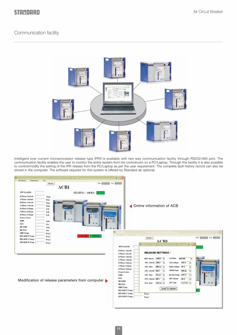
Communication facility
Intelligent over current microprocessor release type IPR3 is available with two way communication facility through RS232/485 port. The communication facility enables the user to monitor the entire system from his controlroom on a PC/Laptop. Through this facility it is also possible to control/modify the setting of the IPR release from the PC/Laptop as per the user requirement. The complete fault history record can also be stored in the computer. The software required for this system is offered by Standard as optional.
Online information of ACB
Modification of release parameters from computer

16
Air Circuit Breaker
Wattloss chart (total for 3 Pole ACB)
V-series

17
Air Circuit Breaker
Accessories
Electrical Accessories Drawout Accessories
Auxillary Contacts
A se t o f f i v e changeove r switches are provided in the c i rcu i t b reaker wh ich can be used for external circuit. Addit ional f ive changeover switches can also be provided as an optional.
Drawout position lock
This feature is available to lock the breaker into different drawout posit ions i.e. CONNECTED, TEST, o r D ISCONNECTED position with the help of padlock (not supplied with ACB).
Charging Motor
I t is provided in an electr ical operated ACB to charge the closing springs automatically. These are available in 110V and 220V AC/DC. The VA burden of th is motor is 150 VA only and the charging time is 3 to 4 seconds.
Safety Shutter for main circuit
It is provided on the cradle which automatically isolates the Main circuit terminals when the breaker is drawn out. A provision is also there for locking the safety shutter in the closed position with the help of Pad Lock (not supplied with ACB).
Shunt Trip Coil/Closing Coil
These coils are used for electrical tripping and closing of ACB.These coils are available in 24V, 110VAC/DC, 220VAC/DC & 415VAC. The same coil can be used as a shunt trip coil or closing coil. The inrush power is 200VA.
These coils are used for electrical tripping and closing of ACB. These coils are available in 24V, 110VAC/DC, 220VAC/DC & 415VAC. The same coil can be used as a shunt trip coil or closing coil. The inrush power is 200VA.
Position Indication Switch
A set of 5 micro switches is provided in the cradle which indicates the position of breaker in the cradle i.e. CONNECTED, TEST, o r D ISCONNECTED position. Two switches each are provided for CONNECTED AND DISCONNECTED position and one switch is for TEST position.
Undervoltage release
This release tr ips the ACB in case the voltage drops below the required level. It is necessary to energise the under voltage release coil before attempting to close the circuit breaker as in de- energized condition, it mechanically locks the breaker and the same can not be closed. These coils are available in 24V DC, 110V AC/DC, 220V AC/DC & 415V AC.
For energizing this coil minimum 85% of the rated voltage is required and if the voltage drops below 50% of the rated voltage it automatically trips the ACB. Inrush power of this coil is 200VA and the continuous power is 5VA only.
Adaptor terminals for Cradle
Special Adaptor Terminals can also be provided for Ist frame A C B w h i c h c a n m a k e t h e terminals su i table for tak ing hor izontal as wel l as vert ical b u s b a r c o n n e c t i o n s . T h e standard cradles are supplied with horizontal terminals. Adaptor terminals are factory fitted and are available at extra cost.
Mal insertion prevention device
It prevents the breaker of a different rating being inserted into the cradle of different rating.

18
Air Circuit Breaker
Other accessories
Key Lock/ Key Interlock
It is provided to lock the ACB in open position. Once the ACB is locked it can not be switched on. For interlocking purpose three locks with two keys or two locks with one key can be supplied.
Door Interlock
It prevents the opening of panel door, if the ACB is in closed (ON) position. When this interlock is fitted in the Circuit Breaker it is necessary to switch off the breaker, before opening the panel door.
Close open cycle Counter
I t i nd i ca tes t he numbe r o f mechanical operations of the circuit breaker and the same is visible on the front of ACB Cover.
Spring charge Indication Switch
A micro switch is provided to get a remote signal indicating the status of Circuit Breaker closing spring.
ON/OFF push button cover
A special cover can be provided on the front cover on which a pad lock (not supplied with ACB) can be fitted for locking the ON & OFF push buttons.
Lifting Plates
Air Circuit Breakers are fitted with specially designed lifting plates which makes the lifting of these ACBs very convenient.
Trip Indication Switch
It is provided to get a remote signal indicating that ACB has tripped due to the operation of over current release.
Safety shutter padlock feature
For the safety of the personnel, safety shutter can be padlocked o n c e t h e b r e a k e r h a s b e e n withdrawn from the cradle.

19
Air Circuit Breaker
Ove
r C
urre
nt R
elea
se
Arc
Chu
te
Cha
rgin
g H
andl
e
Pus
h B
utto
n “O
FF”
Pus
h B
utto
n “O
N”
Cra
dle
Uni
t
Con
trol
Ter
min
als
Pol
e U
nit
Five
Ter
min
al a
ssem
bly
Mov
ing
Con
tact
ass
embl
y
Shu
nt T
rip C
oil
Saf
ety
Shu
tter
Term
inal
s
Pad
lock
faci
lity
for
safe
ty s
hutt
er
Pos
ition
Indi
catio
n S
witc
h (O
ptio
nal)
Mou
ntin
g H
oles
Inte
rnal
vie
w o
f AC
B

20
Air Circuit Breaker
Dimensional details (in mm) - 630A to 2000A (E & S series) fixed type
* Mounting hole dimensions All dimensions are in mm. Thickness - ‘T’
E- Series S- Series
630-800A 10 20
1000-1250A 15 20
1600A 20 20
2000A 25 25

21
Air Circuit Breaker
Dimensional details (in mm) - 630A to 2000A (E & S series) drawout type
* Mounting hole dimensions All dimensions are in mm.Thickness - ‘T’
E- Series S- Series
630-800A 10 20
1000-1250A 15 20
1600A 20 20
2000A 25 25

22
Air Circuit Breaker
Dimensional details (in mm) - 2500A (H series) fixed type
* Mounting hole dimensions All dimensions are in mm.
23
Air Circuit Breaker
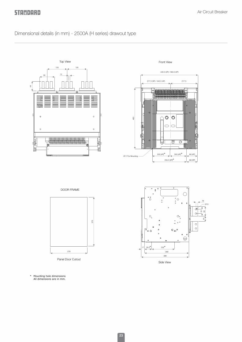
Dimensional details (in mm) - 2500A (H series) drawout type
* Mounting hole dimensions All dimensions are in mm.

24
Air Circuit Breaker
Dimensional details (in mm) - 3200A to 4000A (V series) fixed type
* Mounting hole dimensions All dimensions are in mm. Thickness - ‘T’
Rating ‘T’
3200A 20mm.
4000A 25mm.

25
Air Circuit Breaker
Dimensional details (in mm) - 3200A to 4000A (V series) drawout type
* Mounting hole dimensions All dimensions are in mm.

26
Air Circuit Breaker
Selection chart

27
Air Circuit Breaker
Order form
Please check R in front of appropriate box. Fill separate sheet for each type of ACB
Note :1. Please specify the voltages for closing coil, shunt trip coil and UVT, available voltages are 24VDC, 110VAC/DC, 220VAC/DC and 415V AC and for motor available
voltages are 220V AC / DC and 110V AC / DC.2. For details of Over current release, please refer the technical catalogue.
CUSTOMER / DEALER NAM E ORDER NO. / DA TE
* Horizontal Terminals (H,V)
Fixed DrawoutAdaptor Terminals(for E & S series only)
Closing Coil ______VAC/DC
Manual Electrical Tripping Coil______ VAC/DC
Motor ______ V
Without Release
CT Rating _________ A, Neutral CT
Setting: O/L _________ A, S/C _________ A,
Inst. _________ A, GFT _________ A,
Note: Unless otherwise specified O/L will be set at maximum value and all other settings would be set at mid values.
Key Interlock
Qty.Rating of ACB
OtherAccessories
Mounting
SpringChargingOperation
IPR 3IPR 2IPR 1
Release
2L+1K
3L+2K
No. of Poles 2 3 4
END USER NAME
OFV
-6
630A 1000A 1600A
800A 1250A 2000A
2500A
3200A4000A
Series E S H V
IPR E
(100% Neutral) (50% Neutral for V-Series only)
4
For E & S series - Horizontal terminals are standard, for H & V series vertical terminals are standard. Please specify if other combination is required.*
Key Lock
Shunt Trip Coil
UVT
Trip Indication Switch
Five c/o additionalAux. contacts
............V
Close open cycle counter
Field test unit
Position Indication Switch
Spring Charge Indication Switch
Mechanical Interlock
Mal InsertionPrevention device
Door Interlock
Recommended