Vol-3 Issue-6 2017 IJARIIE-ISSN(O)-2395-4396
7035 www.ijariie.com 729
AC DYNAMIC LOAD CONTROL FROM
SOLAR ENERGY BY USING PHASE-IN
POSITION CONTROL TECHNIQUE
Aparna Abbireddy1, E Prasanna
2
1 Student, EEE Department, Avanthi Institute of Engineering & technology, Telangana, India
2 Assoc.Prof, EEE Department, Avanthi Institute of Engineering & technology, Telangana, India
ABSTRACT This paper presents the design, control and simulation of multifunctional, two-stage, three- Phase SPV energy
conversion system which have been carried out using an control algorithm based on ANF. The ANF has been used
for extraction of fundamental part of load current. The reference grid currents are then estimated using all load
currents, PV contribution and loss component of VSC, which are further used to generate the switching pulses for
VSC. The performance of the system has been demonstrated for harmonics elimination, compensation of reactive
power, load balancing and power factor correction. An InCA technique has been used for the electrical MPPT of
SPV panels. The performance of the two-stage, three-phase grid-interfaced SPV energy system has been found
satisfactory under different dynamics and steady state operating conditions. The THD of grid currents is found well
under IEEE-519 standard. A wide range of simulation results has been shown to prove the feasibility of the control
approach.
Keyword: - PV system, MPPT, dynamic load, grid
1. INTRODUCTION
Due to rising cost of non-renewable sources of energy and also because of environmental concerns caused due to
their use Green and low carbon power is an urgent need today. SPV (Solar Photovoltaic) energy conversion systems,
in comparison with other renewable sources of energy like wind, tidal etc. are gaining momentum due to increased
research in the area, suitable government policies and falling prices. “Solar PV energy conversion systems can be of
two types: grid-interfaced and standalone power generating system”. Standalone systems increase both capital and
maintenance cost of the system, as it require additional energy storage device like batteries for reliable and efficient
operation. Whereas in Grid-interfaced solar energy conversion systems integration of any renewable energy source
to the electric grid has to fulfill standard power quality requirements so that the grid is not polluted due to such
interface. Thus Grid-interfaced solar energy conversion systems do not require any storage device.
The ratio of nonlinear load is increasing in the distribution system like adjustable speed drives, computers, electronic
ballasts, etc. due to lot of electronic devices coming in the market.“These nonlinear loads inject harmonics rich
current into the distribution system, which may cause several other problems like mal-operation of devices
connected to the system, overheating of motor-load and distortion in the supply voltage wave form etc”. Various
custom power devices provide retrofit solutions to these power quality problems. For power quality improvement
various series, shunt, hybrid and shunt-series connected devices are proposed in.
The energy scarcity and poor quality of the supplied power are the challenges encountered in the distribution
system, these challenges are addressed in the proposed system is a multi-function device. “The proposed SPV
energy conversion system is capable of improving the power quality along with the objectives of MPPT” (Maximum
power Point Tracking) and feeding that energy into the grid. For feeding active power to the grid PV inverters are
limited to use , in the literature many single-stage as well as two stage grid interfaced SPV systems are reported.
Very few grid interfaced SPV systems with reactive power compensation and active power filtering are reported in
but they do not provide load currents balancing and also detailed hardware results are not given. However only
simulation studies have been presented in SRFT (Synchronous Reference Frame Theory) based control for grid
Vol-3 Issue-6 2017 IJARIIE-ISSN(O)-2395-4396
7035 www.ijariie.com 730
interfaced SPV system with power quality improvement discussed by Verma et al. Because of low pass filters used
for filtering the SRF theory based system suffers from poor dynamic response.
Two-stage multifunctional SPV generation systems are presented. A complicated neural network based control
approach is used. Here we are discussing about grid-tied systems that utilize batteries for energy storage. We can
rely on the batteries to power our “critical loads” when grid is absent. Critical loads generally consist of
refrigerators, freezers, well pump, some lighting circuits, etc. The batteries are most often maintained in a „float‟
charge where the battery is maintained at full capacity waiting for that critical moment, when we have a grid-tied
system with battery backup.
One knows that how batteries are traditionally incorporated into grid-tied systems, why strictly grid-tied systems are
most often used. To gain higher efficiencies, we focus on a newer type of battery based system that couples the PV
on the AC side of a battery based system. As they are very simple and efficient vast majority of solar PV systems
installed today are strictly grid-tied systems and they do not utilize batteries for energy storage. The least amount of
components are required for the system. They are the solar array, a utility-interactive inverter (to convert the solar
modules DC current to AC current) and installation components for a code compliant system.
The excess energy produced goes onto the electrical grid virtually spinning the utility meter backwards instead of
storing the electrical energy in a battery bank. A credit that is subtracted from the energy consumed every month is
stored as the energy that is delivered to the grid. Often times when the credit amount reaches a certain monetary
value set by the utility, the utility will cut the system owner a check and the energy delivered to the utility exceeds
the amount of energy consumed by the home or business.
When the connection between the grid and the solar PV is interrupted due to a power outage or other event, since
there is no energy storage on site there is no way to utilize the energy from the solar array. Because of the higher
efficiency that it delivers and least expensive this system is most often used.
When grid is absent, some people opt for a system that utilizes batteries to store energy for those events as not being
able to use your solar array during a power outage can be frustrating. The amount of times that backup power is
needed is generally few and the utility is reliable in most areas around Wisconsin. Due to the number of components
and complexity of the system investing in a PV system with battery backup from the get go has always been the
most expensive system.
Fig:1. AC coupled PV system

Vol-3 Issue-6 2017 IJARIIE-ISSN(O)-2395-4396
7035 www.ijariie.com 731
Instead of diverting it to dump loads or wasting that energy, you had the best of both worlds being able to have off-
grid capability and be able to sell excess energy (after batteries were charged up) to the utility. A charge controller is
used to manage the energy from the PV array to effectively charge the battery ,Traditionally a PV array is connected
or „coupled‟ to the DC side of a battery-based system . “The array is wired at a lower voltage to better match the
battery bank”. Many battery inverters will sell excess PV power to the grid when the battery is full. There are more
efficiency losses in the system as a whole (when compared to a strictly grid-interactive inverter) in this
configuration.
During off-grid operation only „critical loads‟ are powered. The system added to an existing PV system can be very
cost effective and give the peace of mind that backup power offers. “The configuration of the PV array doesn‟t need
to be changed at all and only the battery-based inverter, battery bank, battery management components and a
„critical load‟ panel need to be added”. Most importantly the high efficiency of the grid-tied inverter is maintained.
It may be only once or twice a year when the battery system is asked to perform its crucial task and the other 360
days of the year you can utilize your PV at a very high efficiency, powering your loads and selling excess power to
the grid. With the traditional DC coupled array during those other 360 days you may be wasting ¼ of your array
potential only operating at 75%. Solar is hands down a very rewarding investment. AC coupling allows you to have
an even more rewarding experience by giving you the battery backup capacity when the grid is absent while
utilizing your existing, high efficiency PV array. We‟d love to retrofit all of the central Wisconsin grid-tied systems
out there, so give us a call.
In designing a solar power system for the cabin at Enota, we are using the newest most cost-efficient technology.
However, to understand new more efficient methods we researched past projects. By doing so, we can learn from
others mistakes and hardships. By understanding the difficulties we will face, we can be better prepared for them.
The following are two examples and tips from other solar projects [1]. Looking through some do-it-yourself
documents we found the detailed experience of Shane from Rock river. Shane wanted to become more self-
sufficient and decided to start with a solar system consisting of 4, 190 watt solar panels. He documents his
experience very thoroughly on this website and has a few tips we can take from it. Shane says he lowered his
average monthly electric bill by half in just two steps [2].B His first step was to change the incandescent light bulbs
to compact florescent and second was installing timed power strip son the electronic devices with phantom loads. “A
phantom load is when a device is plugged into the wall and is turned off but still uses power when turned off [3].”
The rest of the installation is mostly straight forward and standard but he offers oneother tip about panel positioning.
“It is recommended to tilt your panels to equal your latitude and then for winter months add 15 degrees to the tilt
and in Summer Subtract 15 degrees from the tilt [4].” Bob Goodsell undertook a project similar to ours, installing a
PV system with battery backup [5]. One of the major disadvantages to Bob‟s design was that he did not incorporate
net metering, or selling power back to the grid [6]. During sunny days when the batteries were completely charged,
the rest of his power was just wasted. Our system is designed to have the capability to net meter, thus selling excess
power back to the power company [7]. Another issue Bob ran into is the overheating of his solar panels. “The
conversion of sunlight to electricity is dependent on the temperature of the panels”. If the panels get too hot, the
output will go down. He used the solar shingles directly mounted on his roof, with no air gap behind them and no
aluminum frame to dissipate heat. Because of this, his output in May was higher than in July. Our system utilizes
panels with aluminum frames to help dissipate heat. Also, both mounting options have sufficient air gap under the
panels, keeping them at a normal temperature. Also, Bob used flooded non-sealed batteries. Thus he has to maintain
the water level of these batteries to prevent damage or battery failure, as well as vent dangerous fumes out of his
house. Our system uses sealed batteries, so there is never any off gassing or need to check any fluid levels [8] S.
Yuvarajan et al proposed a fast and accurate maximum power point tracking (MPPT) algorithm for a photovoltaic
(PV) panel that uses the open circuit voltage and the short circuit current of the PV panel [8]. The mathematical
equations describing the nonlinear V-I characteristics of the PV panel were used in developing the algorithm.
The MPPT algorithm is valid under different insulation, temperature, and level of degradation. The algorithm is
verified using MATLAB and it is found that the results obtained using the algorithm were very close to the
theoretical values over a wide range of temperature and illumination levels. The maximum deviation in the
maximum power was less than 1.5% for the illumination levels and temperatures normally encountered by a
commercial PV panel. The complete derivation of this MPPT algorithm was presented [9]. It is seen that the
algorithm is faster than other MPPT algorithms like perturbation and observation (P&O) and more accurate than
approximate methods that use the linearity between voltage (current) at maximum power point and open-circuit
voltage (short-circuit current).Prof. Dr. IlhamiColak, et al. have modeled three separate solar farms that provide
[10]. 15 kW power for each farm using Mat lab Simulink real-time analysis software [11]. Energy conversion was
performed with maximum power point tracking (MPPT) algorithms in each converter using Perturb and Observe
Vol-3 Issue-6 2017 IJARIIE-ISSN(O)-2395-4396
7035 www.ijariie.com 732
(P&O) structure. These were collected in DC bus bar with parallel connection of converters over inter-phase
transformers (IPT). The voltage was applied to a full bridge inverter to generate 3-phase AC voltages at the output
of inverter which was controlled with sinusoidal pulse width modulation (SPWM) scheme [12]. S. G. Tesfahunegn
et al. designed a new solar/battery charge controller that combines both MPPT and over-voltage controls as single
control function [10]. A small-signal model of lead acid battery was derived in detail to design the employed dual-
loop control configuration. Case studies were then conducted, in SIMULINK/SIMPOWER, to evaluate the
performance of the designed controller in terms of transient response and voltage overshoot [13].
The designed controller was demonstrated to have good transient response with only small voltage overshoot.
Yuncong Jiang et.al. Present an analogue Maximum Power Point Tracking (MPPT) controller for a Photovoltaic
(PV) solar system that utilizes the load current to achieve maximum output power from the solar panel [14].
Comparing to the existing MPPT controller circuitry which requires multiplication of the sensed PV panel voltage
and current to yield panel power, the cost and size of the proposed circuit was reduced. The tracking performance of
the proposed MPPT controller was validated by simulation results. ArashShafie et al proposed a novel MPPT
algorithm mainly for battery charging applications which were considered constant voltage type loads. This was
achieved mainly with output current maximization [12]. This technique benefits from advantages such as very
simple current controller and also circuit topology independency. This provides high efficiency for energy
conversion with low cost for low power, low cost applications. A new hybrid PV model was introduced for
simulation purposes. Finally, simulation results will be provided confirming the validity of the algorithm. Solar
photovoltaic (PV) systems have been an area of active research for the last few decades to improve the efficiency of
solar PV module. The non-linear nature of IV curve of solar PV module demands some technique to track the
maximum voltage and maximum current point on IV curve corresponding to Maximum Power Point (MPP)[11].
The proposed MPPT technique was much more robust in tracking the MPP even under the frequent changing
irradiance conditions and was less oscillatory around the MPP as compared to P&O. The technique was verified
using MATLAB/SIMULNK and simulation results show a clear improvement in achieving the MPP when subjected
to change in irradiance
2. GRID CONNECTED SYSTEM
When connecting a home energy system to the electric grid, research and consider equipment required as well as
your power provider‟s requirements and agreements. | Photo courtesy of Solar Design Associates, Inc. Many people
prefer the advantages that grid-connection offers, even renewable energy systems are capable of powering houses
and small businesses without any connection to the electricity grid. During the periods (daily as well as seasonally)
like when the sun is shining, the water is running, or the wind is blowing, a grid-connected system allows you to
power your home or small business with renewable energy. Any excess electricity you produce is fed back into the
grid. Eliminating the expense of electricity storage devices like batteries, electricity from the grid supplies your
needs when renewable resources are unavailable. In addition, power providers (i.e., electric utilities) in most states
allow net metering, an arrangement where the excess electricity generated by grid-connected renewable energy
systems "turns back" your electricity meter as it is fed back into the grid. If you use more electricity than your
system feeds into the grid during a given month, you pay your power provider only for the difference between what
you used and what you produced. When thinking about connecting your home energy system to the electric grid
some of the things you need to know. They are :
Equipment required to connect your system to the grid
Grid-connection requirements from your power provider
State and community codes and requirements
In order to safely transmit electricity to your loads and comply with your power provider's grid-connection
requirements, you will need to purchase some additional equipment, aside from the major small renewable energy
system components. You may need the following items:
Power conditioning equipment
Safety equipment
Meters and instrumentation.
Because grid-connection requirements vary, you or your system supplier/installer should contact your power
provider to learn about its specific grid-connection requirements before purchasing any part of your renewable
energy system. Page on balance-of-system gives the equipment requirements for small renewable energy systems.
2.1 Grid-Connection Requirements from Your Power Provider:
Currently, requirements for connecting distributed generation systems—like home renewable energy or wind
systems—to the electricity grid vary widely. But all power providers face a common set of issues in connecting

Vol-3 Issue-6 2017 IJARIIE-ISSN(O)-2395-4396
7035 www.ijariie.com 733
small renewable energy systems to the grid, so regulations usually have to do with safety and power quality,
contracts (which may require liability insurance), and metering and rates. Try contacting your state utilities
commission, state utility consumer advocate group (represents the interests of consumers before state and federal
regulators and in the courts), state consumer representation office, or state energy office, if your power provider
does not have an individual assigned to deal with grid-connection requests. To learn about its specific requirements,
you will need to contact your power provider directly.
2.2Addressing Safety and Power Quality for Grid Connection: Power providers want to be sure that your system includes safety and power quality components. These components
include switches to disconnect your system from the grid in the event of a power surge or power failure (so
repairmen are not electrocuted) and power conditioning equipment to ensure that your power exactly matches the
voltage and frequency of the electricity flowing through the grid.
2.3 Contractual Issues for Grid-Connected Systems:
You will probably need to sign an interconnection agreement with your power provider, when connecting your small
renewable energy system to the grid. Power providers may require you to do the following in your agreement:
Carry liability insurance -- Liability insurance protects the power provider in the event of accidents resulting
from the operation of your system. Most homeowners carry at least $100,000 of liability through their homeowner
insurance policies (although you should verify that your policy will cover your system), which is often sufficient. Be
aware, however, that your power provider may require that you carry more. Some power providers may also require
you to indemnify them for any potential damage, loss, or injury caused by your system, which can sometimes be
prohibitively expensive.
Pay fees and other charges -- You may be asked to pay permitting fees, engineering/inspection fees, metering
charges (if a second meter is installed), and stand-by charges (to defray the power provider's cost of maintaining
your system as a backup power supply). Identify these costs early so you can factor them into the cost of your
system, and don't be afraid to question any that seem inappropriate.
In addition to insurance and fees, you may find that your power provider requires a great deal of paperwork before
you can move ahead with your system. However, power providers in several states are now moving to streamline the
contracting process by simplifying agreements, establishing time limits for processing paper work, and appointing
representatives to handle grid-connection inquiries.
2.4Metering and Rate Arrangements for Grid-Connected Systems:
When your renewable energy system generates more electricity than you can use at that moment, the electricity goes
onto the electric grid for your utility to use elsewhere,with a grid-connected system. The Public Utility Regulatory
Policy Act of 1978 (PURPA) requires power providers to purchase excess power from grid-connected small
renewable energy systems at a rate equal to what it costs the power provider to produce the power itself. Through
various metering arrangements power providers generally implement this requirement. Here are the metering
arrangements you are likely to encounter:
Net purchase and sale -- Under this arrangement, two uni-directional meters are installed: one records
electricity drawn from the grid, and the other records excess electricity generated and fed back into the grid. You
pay retail rate for the electricity you use, and the power provider purchases your excess generation at its avoided
cost (wholesale rate). There may be a significant difference between the retail rate you pay and the power provider's
avoided cost.
Net metering -- Net metering provides the greatest benefit to you as a consumer. Under this arrangement, a
single, bi-directional meter is used to record both electricity you draw from the grid and the excess electricity your
system feeds back into the grid. The meter spins forward as you draw electricity, and it spins backward as the excess
is fed into the grid. If, at the end of the month, you've used more electricity than your system has produced, you pay
retail price for that extra electricity. If you've produced more than you've used, the power provider generally pays
you for the extra electricity at its avoided cost. The real benefit of net metering is that the power provider essentially
pays you retail price for the electricity you feed back into the grid. Some power providers will now let you carry
over the balance of any net extra electricity your system generates from month to month, which can be an advantage
if the resource you are using to generate your electricity is seasonal. If, at the end of the year, you have produced
more than you've used, you forfeit the excess generation to the power provider. In an attempt to address safety and
power quality issues, several organizations are developing national guidelines for equipment manufacture, operation,
and installation (your supplier/installer, a local renewable energy organization, or your power provider will know
which of the standards apply to your situation, and how to implement them):
Vol-3 Issue-6 2017 IJARIIE-ISSN(O)-2395-4396
7035 www.ijariie.com 734
The Institute of Electrical and Electronics Engineers (IEEE) has written a standard that addresses all grid-
connected distributed generation including renewable energy systems. IEEE 1547-2003 provides technical
requirements and tests for grid-connected operation. See the IEEE Standards Coordinating Committee on Fuel Cells,
Photovoltaics, Dispersed Generation, and Energy Storage for more information.
Underwriters Laboratories (UL) has developed UL 1741 to certify inverters, converters, charge controllers, and
output controllers for power-producing stand-alone and grid-connected renewable energy systems. UL 1741 verifies
that inverters comply with IEEE 1547 for grid-connected applications.
The National Electrical Code (NEC), a product of the National Fire Protection Association, deals with electrical
equipment and wiring safety.
Although states and power providers are not federally mandated to adopt these codes and standards, a number of
utility commissions and legislatures now require regulations for distributed generation systems to be based on the
IEEE, UL, and NEC standards. In addition, some states are now "pre-certifying" specific models of equipment as
safe to connect to the state electricity grid.
3. AC COUPLING – CONVERTING GRID TIED PV SYSTEM
With solar panels through better efficiency rates, net metering, plus lower equipment and installation costs,a grid-
connection will allow you to save more money: For a fully functional off-grid solar system batteries, and other
stand-alone equipment, are required and add to costs as well as maintenance. Therefore, Grid-tied solar systems are
generally cheaper and simpler to install. Often more electricity than what you are capable of consuming is generated
by your solar panels. Instead of storing it themselves with batteries with net metering, homeowners can put this
excess electricity onto the utility grid. How solar power is incentivized, net metering (or feed-in tariff schemes in
some countries) play an important role. Without it, residential solar systems would be much less feasible from a
financial point of view. Many utility companies are committed to buying electricity from homeowners at the same
rate as they sell it themselves. Electricity has to be spent in real time. However, it can be temporarily stored as other
forms of energy (e.g. chemical energy in batteries). Energy storage typically comes with significant losses. A
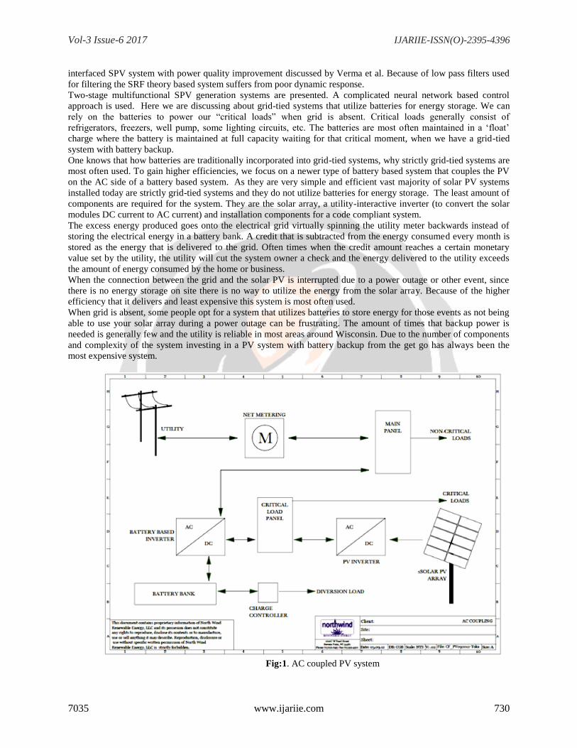
schematic diagram of two-stage grid interfaced SPV generating system is shown in Fig.2. The proposed system
consists of SPV panels, a dc-dc boost converter, and a three-leg VSC. A two-stage grid connected SPV energy
conversion system is used in this work. In first stage, the solar photovoltaic modules are connected in a suitable
series-parallel combination to get the desired voltage and current rating from the panels.
Fig: 2.Two-stage Grid-interfaced SPV generation system
. The load current mainly consists of fundamental, harmonics and dc components. The fundamental portion of load
current can be further divided into current in-phase and 90° shifted with respect to respective phase voltage. An
adaptive theory-based notch filter [25]-[26] with adaptive frequency is used to estimate the fundamental part of load
current of phase“a”(iLfa), as shown in the block diagram of Fig. 2. An adaptive notch filter (ANF) based control
technique is used to estimate.
Vol-3 Issue-6 2017 IJARIIE-ISSN(O)-2395-4396
7035 www.ijariie.com 735
4. SIMULATION CIRCUITS AND RESULTS
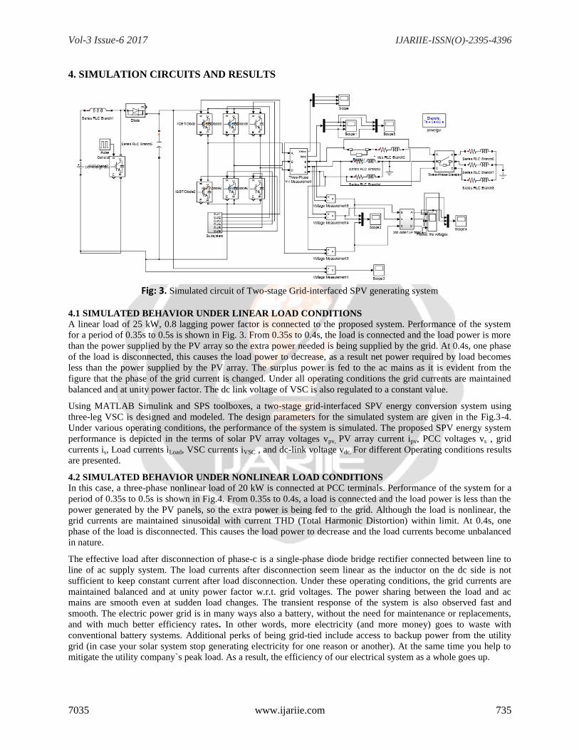
Fig: 3. Simulated circuit of Two-stage Grid-interfaced SPV generating system
4.1 SIMULATED BEHAVIOR UNDER LINEAR LOAD CONDITIONS
A linear load of 25 kW, 0.8 lagging power factor is connected to the proposed system. Performance of the system
for a period of 0.35s to 0.5s is shown in Fig. 3. From 0.35s to 0.4s, the load is connected and the load power is more
than the power supplied by the PV array so the extra power needed is being supplied by the grid. At 0.4s, one phase
of the load is disconnected, this causes the load power to decrease, as a result net power required by load becomes
less than the power supplied by the PV array. The surplus power is fed to the ac mains as it is evident from the
figure that the phase of the grid current is changed. Under all operating conditions the grid currents are maintained
balanced and at unity power factor. The dc link voltage of VSC is also regulated to a constant value.
Using MATLAB Simulink and SPS toolboxes, a two-stage grid-interfaced SPV energy conversion system using
three-leg VSC is designed and modeled. The design parameters for the simulated system are given in the Fig.3-4.
Under various operating conditions, the performance of the system is simulated. The proposed SPV energy system
performance is depicted in the terms of solar PV array voltages vpv, PV array current ipv, PCC voltages vs , grid
currents is, Load currents iLoad, VSC currents iVSC , and dc-link voltage vdc. For different Operating conditions results
are presented.
4.2 SIMULATED BEHAVIOR UNDER NONLINEAR LOAD CONDITIONS
In this case, a three-phase nonlinear load of 20 kW is connected at PCC terminals. Performance of the system for a
period of 0.35s to 0.5s is shown in Fig.4. From 0.35s to 0.4s, a load is connected and the load power is less than the
power generated by the PV panels, so the extra power is being fed to the grid. Although the load is nonlinear, the
grid currents are maintained sinusoidal with current THD (Total Harmonic Distortion) within limit. At 0.4s, one
phase of the load is disconnected. This causes the load power to decrease and the load currents become unbalanced
in nature.
The effective load after disconnection of phase-c is a single-phase diode bridge rectifier connected between line to
line of ac supply system. The load currents after disconnection seem linear as the inductor on the dc side is not
sufficient to keep constant current after load disconnection. Under these operating conditions, the grid currents are
maintained balanced and at unity power factor w.r.t. grid voltages. The power sharing between the load and ac
mains are smooth even at sudden load changes. The transient response of the system is also observed fast and
smooth. The electric power grid is in many ways also a battery, without the need for maintenance or replacements,
and with much better efficiency rates. In other words, more electricity (and more money) goes to waste with
conventional battery systems. Additional perks of being grid-tied include access to backup power from the utility
grid (in case your solar system stop generating electricity for one reason or another). At the same time you help to
mitigate the utility company`s peak load. As a result, the efficiency of our electrical system as a whole goes up.

Vol-3 Issue-6 2017 IJARIIE-ISSN(O)-2395-4396
7035 www.ijariie.com 736
Fig: 4. Simulated results of Two-stage Grid-interfaced SPV generating System
Fig: 5. Simulated results of Two-stage Grid-interfaced SPV generating System
Vol-3 Issue-6 2017 IJARIIE-ISSN(O)-2395-4396
7035 www.ijariie.com 737
4.3 EXTENSION CIRCUIT AND RESULTS
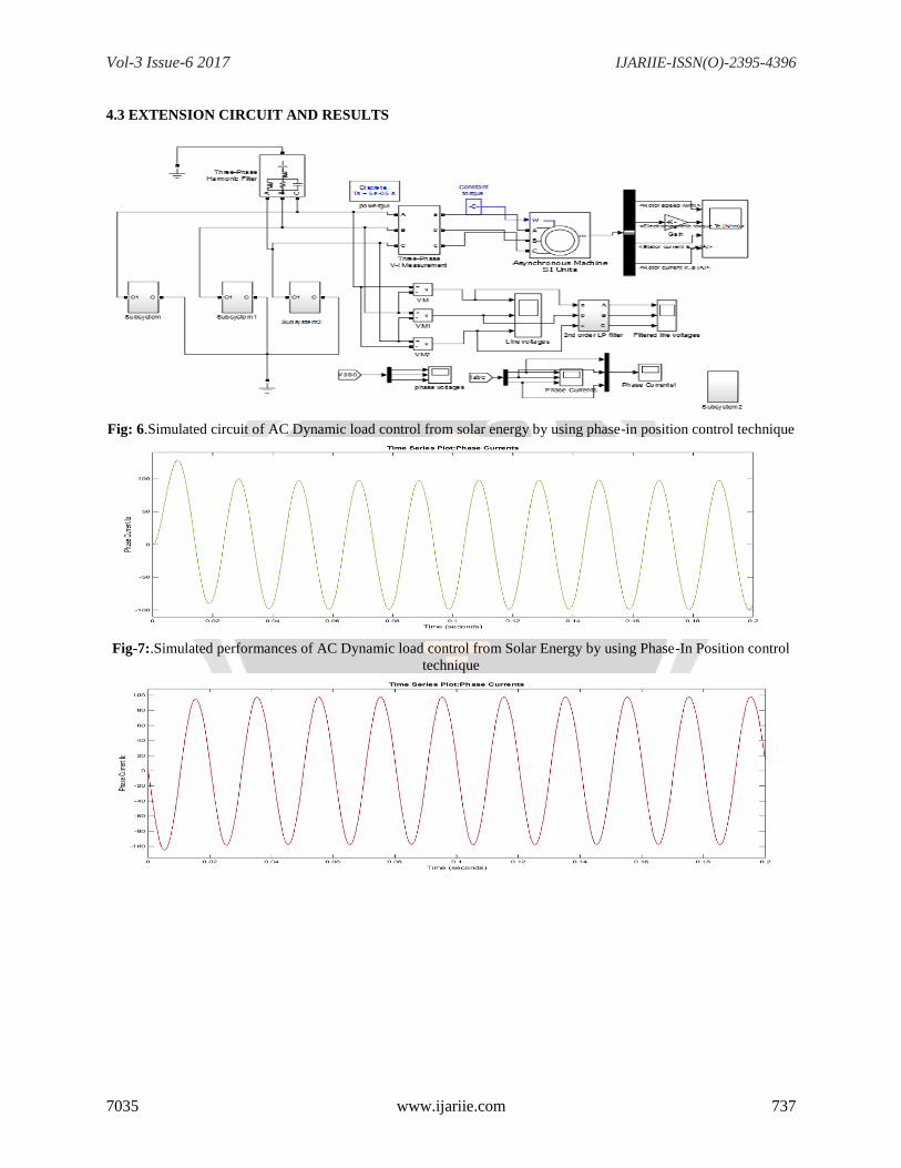
Fig: 6.Simulated circuit of AC Dynamic load control from solar energy by using phase-in position control technique
Fig-7:.Simulated performances of AC Dynamic load control from Solar Energy by using Phase-In Position control
technique

Vol-3 Issue-6 2017 IJARIIE-ISSN(O)-2395-4396
7035 www.ijariie.com 738
Fig:8 (a).Plot of Phase Currents VS Time(seconds)
Fig-9 .Plot of Line voltages VS Time(seconds)
Vol-3 Issue-6 2017 IJARIIE-ISSN(O)-2395-4396
7035 www.ijariie.com 739
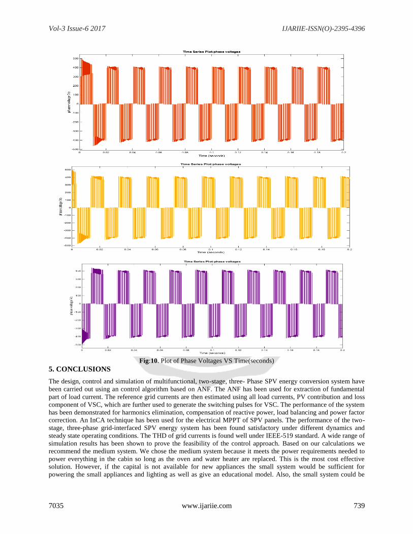
Fig:10. Plot of Phase Voltages VS Time(seconds)
5. CONCLUSIONS
The design, control and simulation of multifunctional, two-stage, three- Phase SPV energy conversion system have
been carried out using an control algorithm based on ANF. The ANF has been used for extraction of fundamental
part of load current. The reference grid currents are then estimated using all load currents, PV contribution and loss
component of VSC, which are further used to generate the switching pulses for VSC. The performance of the system
has been demonstrated for harmonics elimination, compensation of reactive power, load balancing and power factor
correction. An InCA technique has been used for the electrical MPPT of SPV panels. The performance of the two-
stage, three-phase grid-interfaced SPV energy system has been found satisfactory under different dynamics and
steady state operating conditions. The THD of grid currents is found well under IEEE-519 standard. A wide range of
simulation results has been shown to prove the feasibility of the control approach. Based on our calculations we
recommend the medium system. We chose the medium system because it meets the power requirements needed to
power everything in the cabin so long as the oven and water heater are replaced. This is the most cost effective
solution. However, if the capital is not available for new appliances the small system would be sufficient for
powering the small appliances and lighting as well as give an educational model. Also, the small system could be

Vol-3 Issue-6 2017 IJARIIE-ISSN(O)-2395-4396
7035 www.ijariie.com 740
upgraded to a larger system at some point in the future. The Pros and cons of the MPPT algorithms It is noted that
perturb and observe and incremental conductance is superior to all other MPPT algorithms. Though fuzzy and neural
networks are developing in the present days, the efficiency remains high in perturb and observe and Incremental
conductance methods. The converters such as buck, boost, buck-boost, buck converters are being used in MPPT
systems. PWM inverters are used for grid interconnection and standalone AC loads. The selection of converters is
based on the load connected to the system. The ripples in dc voltage and current also influence the selection of
converters. With the above mentioned converters and MPPT algorithms, solar panels can be configured to feed any
kind of load. The vast development in improving efficiency of MPPT algorithms can encourage domestic generation
of power using solar panels.
6. REFERENCES
[1] N. Jain, S. N. Singh and S.C. Srivastava, “A Generalized Approach for DG Planning and Viability Analysis
Under Market Scenario,” IEEETransactions on Industrial Electronics, vol. 60, no. 11, pp. 5075-5085,Nov.
2013.
[2] G.G. Pozzebon, A.F.Q. Goncalves, G.G. Pena, N.E.M. Mocambique andR.Q. Machado, “Operation of a Three-
Phase Power Converter Connected to a Distribution System,” IEEE Transactions on IndustrialElectronic, vol.
60, no. 5, pp.1810-1818, May 2013.
[3] Espinoza, E. Barcenas, D. Campos-Delgado and C. De Angelo, “Voltage-Oriented Input-Output Linearization
Controller as Maximum Power Point Tracking Technique for Photovoltaic Systems,” IEEETransactions on
Industrial Electronics, Early access.IEEE Recommended Practices and requirement for Harmonic Control on
Electric Power System, IEEE Std. 519, 1992.
[4] Byunggyu Yu, Mikihiko Matsui and Gwonjong Yu “A review of current anti-islanding methods for
photovoltaic power system,” Solar Energy,vol. 84, pp. 745-754, 2010.
[5] Antonio Moreno Munoz, Power Quality: Mitigation Technologies in a Distributed Environment, Springer-
Verlag, London, 2007.
[6] M.S. Hamad, M.I. Masoud, K.H. Ahmed and B.W. Williams, “A Shunt Active Power Filter for a Medium-
Voltage 12-Pulse Current SourceConverter Using Open Loop Control Compensation,” IEEETransactions on
Industrial Electronics, vol. 61, no. 11, pp. 5840-5850,Nov. 2014.
[7] J.D. Barros and J.F. Silva, “Multilevel Optimal Predictive DynamicVoltage Restorer," IEEE Transactions
on Industrial Electronics, vol. 57, no. 8, pp. 2747-2760, Aug. 2010.
[8] C. Kumar and M.K. Mishra, “An Improved Hybrid DSTATCOMTopology to Compensate reactive and
Nonlinear Loads,” IEEETransactions on Industrial Electronics, vol. 61, no. 12, pp. 6517-6527,Dec. 2014.
[9] B.W. Franca, L.F. da Silva, M.A. Aredes and M. Aredes, “An Improved iUPQC Controller to Provide
Additional Grid-Voltage Regulation as a STATCOM,” IEEE Transactions on Industrial Electronics, Early
access.
[10] Chen Yang and K. M. Smedley, “A cost-effective single-stage inverter with maximum power point tracking,”
IEEE Transactions on PowerElectronics, vol.19, no.5, pp.1289-1294, Sept. 2004.
[11] D. Casadei, G. Grandi and C. Rossi, “Single-phase single-stage photovoltaic generation system based on a
ripple correlation control maximum power point tracking,” IEEE Transactions on EnergyConversion, vol.21,
no.2, pp.562-568, June 2006.
[12] Wu Libo, Zhao Zhengming and Liu Jianzheng, “A Single-Stage Three-Phase Grid-Connected Photovoltaic
System with Modified MPPTMethod and Reactive Power Compensation,” IEEE Transactions onEnergy
Conversion, vol.22, no.4, pp.881-886, Dec. 2007.
[13] Huang-Jen Chiu, Yu-Kang Lo, Chun-Yu Yang, Shih-Jen Cheng, Chi-Ming Huang, Ching-Chun Chuang, Min-
ChienKuo, Yi-Ming Huang, Yuan-Bor Jean and Yung-Cheng Huang, “A module-integrated isolated solar
microinverter,” IEEE Transactions on Industrial Electronics, vol. 60, no. 2, pp. 781-788, Feb. 2013.
[14] R. Mechouma, B. Azoui and M. Chaabane, “Three- Phase Grid Connected Inverter for Photovoltaic Systems, a
Review,” InternationalConference on Renewable Energies and Vehicular Technology, 2012.
Recommended