ABRASIVE JET MACHINING
AND
STUDY OF PROCESS PARAMETERS
Abrasive Jet Machine
Introduction
Abrasive jet machining (AJM) is a non-traditional machining
process that can machine material without generating heat and
shock.
Abrasive jet machining (AJM) is commonly used for Cutting,
Cleaning, Drilling and Etching operation
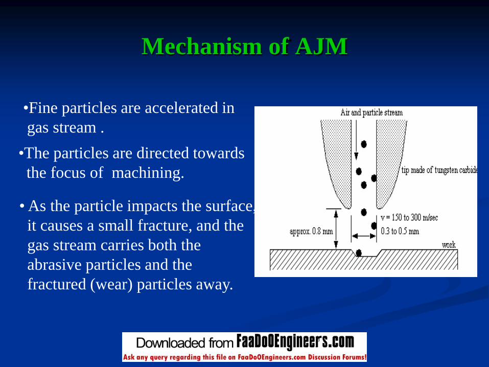
Mechanism of AJM
•Fine particles are accelerated in
gas stream .
•The particles are directed towards
the focus of machining.
• As the particle impacts the surface,
it causes a small fracture, and the
gas stream carries both the
abrasive particles and the
fractured (wear) particles away.

Conventional
Abrasive Jet Machine
Compressor

Constructional Details
Equipments involved in the construction of the
“ Abrasive Jet Machine” are as follows
1. COMPRESSOR
2. VIBRATOR
3. MIXING CHAMBER
5. MACHINE TABLE
4. NOZZLE
6. PRESSURE GAUGE & REGULATOR
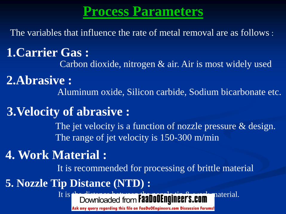
Process Parameters
1.Carrier Gas :Carbon dioxide, nitrogen & air. Air is most widely used
3.Velocity of abrasive :The jet velocity is a function of nozzle pressure & design.
The range of jet velocity is 150-300 m/min
4. Work Material :It is recommended for processing of brittle material
2.Abrasive :Aluminum oxide, Silicon carbide, Sodium bicarbonate etc.
5. Nozzle Tip Distance (NTD) :It is the distance between the nozzle tip & work material.
The variables that influence the rate of metal removal are as follows :
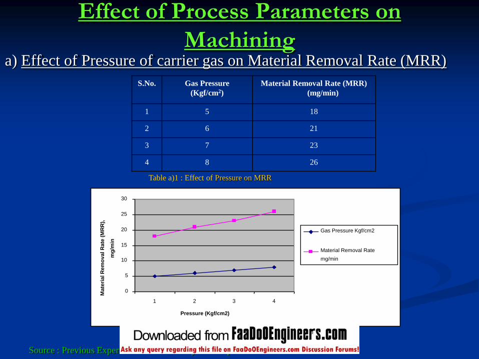
Effect of Process Parameters on
Machininga) Effect of Pressure of carrier gas on Material Removal Rate (MRR)
S.No. Gas Pressure
(Kgf/cm2)
Material Removal Rate (MRR)
(mg/min)
1 5 18
2 6 21
3 7 23
4 8 26
Source : Previous Experiments conducted by M. Roopa Rani and S. Seshan
0
5
10
15
20
25
30
1 2 3 4
Pressure (Kgf/cm2)
Mate
rial R
em
ov
al
Rate
(M
RR
),
mg
/min
Gas Pressure Kgf/cm2
Material Removal Rate
mg/min
Table a)1 : Effect of Pressure on MRR
Fig a)1 : Effect of Pressure on MRR
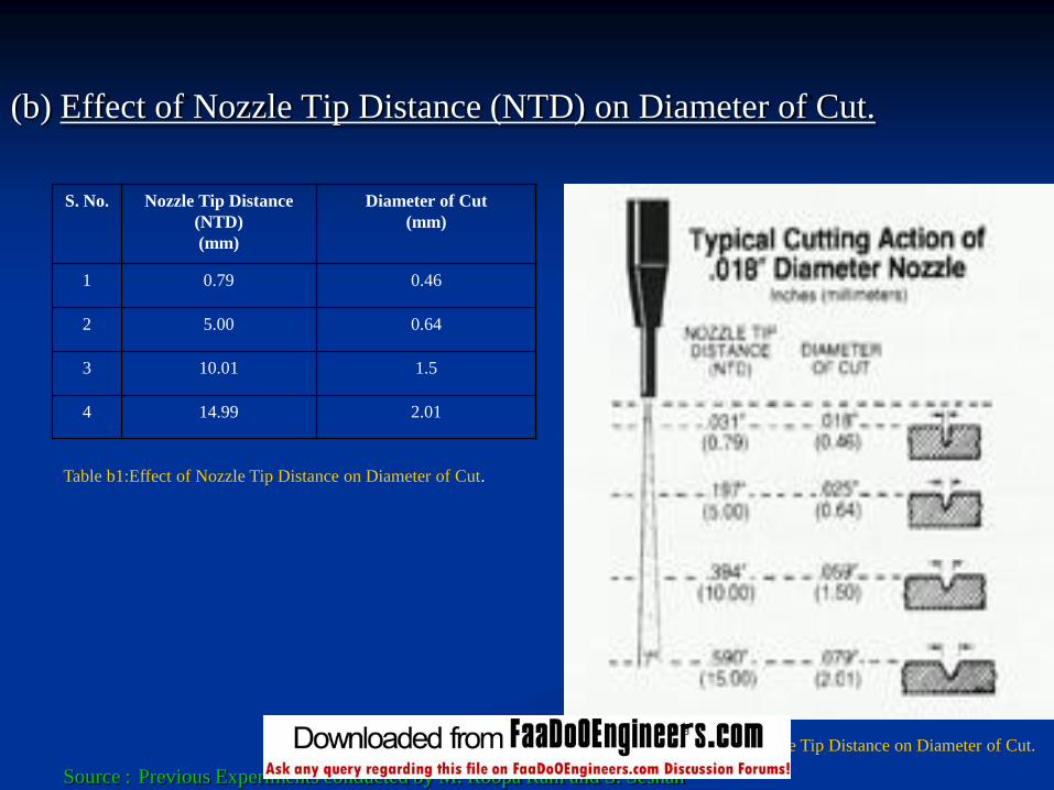
(b) Effect of Nozzle Tip Distance (NTD) on Diameter of Cut.
S. No. Nozzle Tip Distance
(NTD)
(mm)
Diameter of Cut
(mm)
1 0.79 0.46
2 5.00 0.64
3 10.01 1.5
4 14.99 2.01
Source : Previous Experiments conducted by M. Roopa Rani and S. Seshan
Table b1:Effect of Nozzle Tip Distance on Diameter of Cut.
Fig b1:Shows the effect of Nozzle Tip Distance on Diameter of Cut.
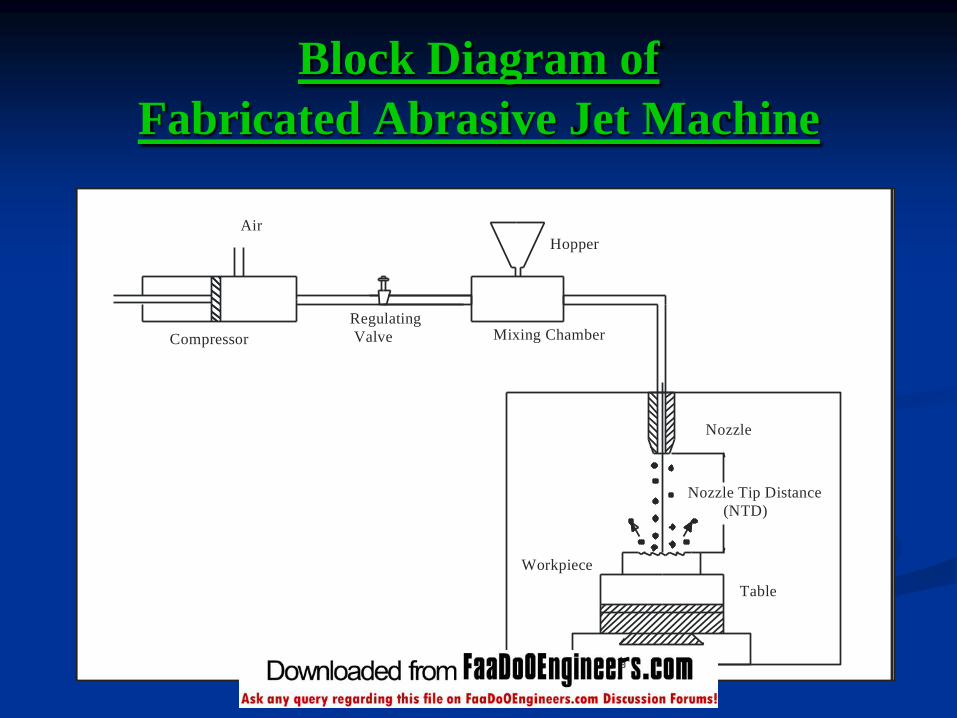
Block Diagram of
Fabricated Abrasive Jet Machine
Workpiece
Table
Nozzle Tip Distance
(NTD)
Nozzle
Mixing Chamber
Hopper
Regulating
ValveCompressor
Air
Abrasive Jet Machine

Photograph of
Fabricated Abrasive Jet Machine
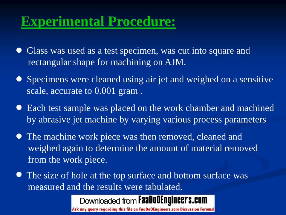
Experimental Procedure:
Glass was used as a test specimen, was cut into square and
rectangular shape for machining on AJM.
Specimens were cleaned using air jet and weighed on a sensitive
scale, accurate to 0.001 gram .
Each test sample was placed on the work chamber and machined
by abrasive jet machine by varying various process parameters
The machine work piece was then removed, cleaned and
weighed again to determine the amount of material removed
from the work piece.
The size of hole at the top surface and bottom surface was
measured and the results were tabulated.

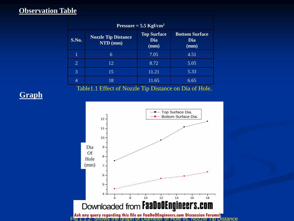
Experimental Details:
Experiment No:1- NTD Vs Diameter of Hole
Observation – 1.1
1 2 3 4NTD=6 NTD=12 NTD=15 NTD=18
Fig.1.1.1 Machined Work piece at Pressure = 5.5 kgf/cm2
Thickness of material = 4 mm
5.33
Observation Table
6.6511.65184
11.21153
5.058.72122
4.517.0561
Bottom Surface
Dia
(mm)
Top Surface
Dia
(mm)
Nozzle Tip Distance
NTD (mm)S.No.
Pressure = 5.5 Kgf/cm2
Table1.1 Effect of Nozzle Tip Distance on Dia of Hole.
Fig 1.1.2. Shows the graph of Diameter of Hole vs. Nozzle Tip Distance
6 8 10 12 14 16 18
4
5
6
7
8
9
10
11
12
NT
D (
mm
)
Diameter of hole (mm)
Top Surface Dia.
Bottom Surface Dia.
Dia
Of
Hole
(mm)
NTD (mm)
Graph
Experiment No:1- NTD Vs Diameter of Hole
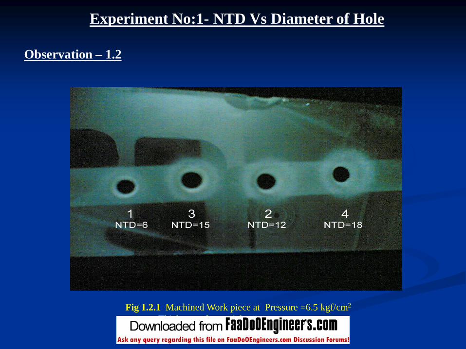
Observation – 1.2
Fig 1.2.1 Machined Work piece at Pressure =6.5 kgf/cm2
Thickness of material = 4 mm
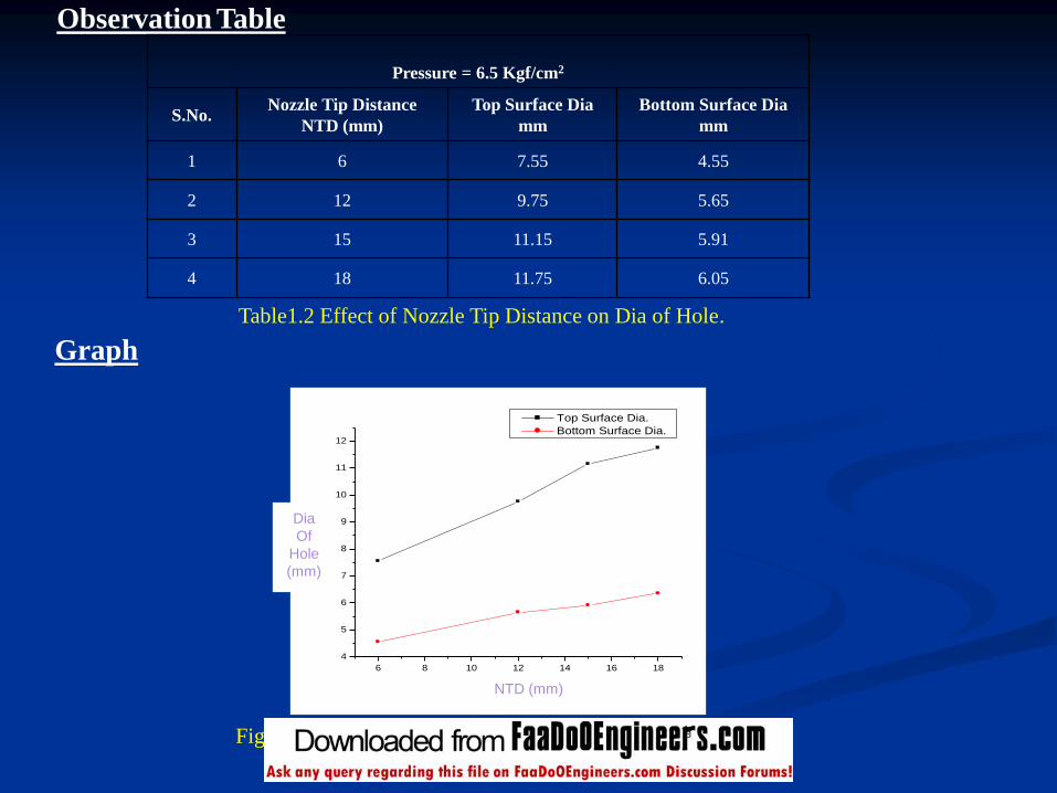
Observation Table
Pressure = 6.5 Kgf/cm2
S.No.Nozzle Tip Distance
NTD (mm)
Top Surface Dia
mm
Bottom Surface Dia
mm
1 6 7.55 4.55
2 12 9.75 5.65
3 15 11.15 5.91
4 18 11.75 6.05
Table1.2 Effect of Nozzle Tip Distance on Dia of Hole.
6 8 10 12 14 16 18
4
5
6
7
8
9
10
11
12
NT
D (
mm
)
Diameter of hole (mm)
Top Surface Dia.
Bottom Surface Dia.
NTD (mm)
Dia
Of
Hole
(mm)
Fig 1.2.2 Graph of Diameter of Hole vs. Nozzle Tip Distance
Graph
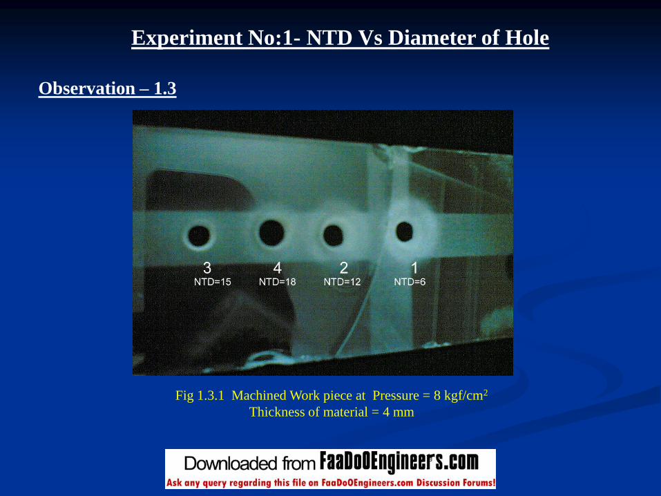
Fig 1.3.1 Machined Work piece at Pressure = 8 kgf/cm2
Thickness of material = 4 mm
Experiment No:1- NTD Vs Diameter of Hole
Observation – 1.3

Observation Table
Pressure = 8 Kgf/cm2
S.No.Nozzle Tip Distance
NTD (mm)
Top Surface Dia
mm
Bottom Surface Dia
mm
1 6 7.72 5.05
2 12 9.95 5.75
3 15 11.45 5.96
4 18 11.81 6.75
Table1.3 Effect of Nozzle Tip Distance on Dia of Hole
6 8 10 12 14 16 18
5
6
7
8
9
10
11
12
NT
D (
mm
)
Diameter of Hole (mm)
Top Surface Dia.
Bottom Surface Dia.
Dia
Of
Hole
(mm)
NTD (mm)
Graph
Fig1.3.2 Graph of Diameter of Hole vs. Nozzle Tip Distance

Experiment No:2- Pressure Vs Material Removal Rate (MRR)
Observation - 2.1
Fig 2.1.1 Machined work piece for determination of MRR at Pr.=5.5 kgf/cm2
Pressure 5.5 kgf/cm2 Initial weight = 140.190 gm
Final Weight = 140.150 gm Time = 20 sec
Thickness = 8mm MRR = 120 mg/min
Fig 2.1.2 Machined work piece for determination of MRR at Pr.=6.5 kgf/cm2
Pressure 6.5 kgf/cm2 Initial weight = 141.200 gm
Final Weight = 141.130 gm Time = 20 sec
Thickness = 8mm MRR = 210 mg/min
Fig.2.1.3 Machined work piece for determination of MRR at Pr.=7.5 kgf/cm2
Pressure 7.5 kgf/cm2 Initial weight = 137.530 gm
Final Weight = 137.370 gm Time = 20 sec
Thickness = 8mm MRR = 400 mg/min
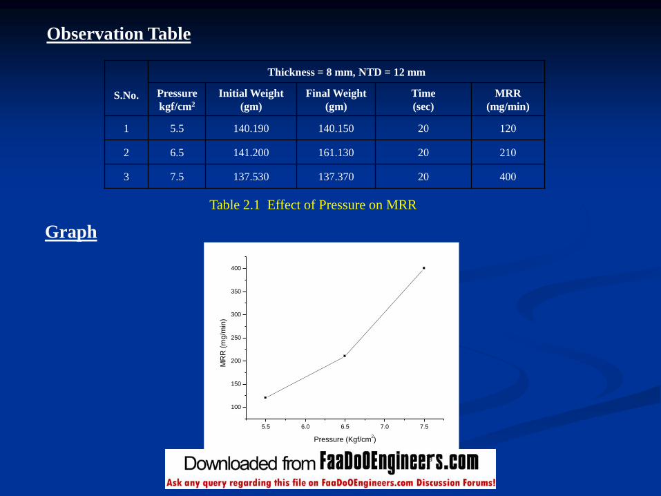
Observation Table
S.No.
Thickness = 8 mm, NTD = 12 mm
Pressure
kgf/cm2
Initial Weight
(gm)
Final Weight
(gm)
Time
(sec)
MRR
(mg/min)
1 5.5 140.190 140.150 20 120
2 6.5 141.200 161.130 20 210
3 7.5 137.530 137.370 20 400
Table 2.1 Effect of Pressure on MRR
5.5 6.0 6.5 7.0 7.5
100
150
200
250
300
350
400
MR
R (
mg/m
in)
Pressure (Kgf/cm2)
Fig.2.1.4 Graph of Pressure vs. MRR
Graph
Experiment No:2- Pressure Vs Material Removal Rate (MRR)
Observation - 2.2
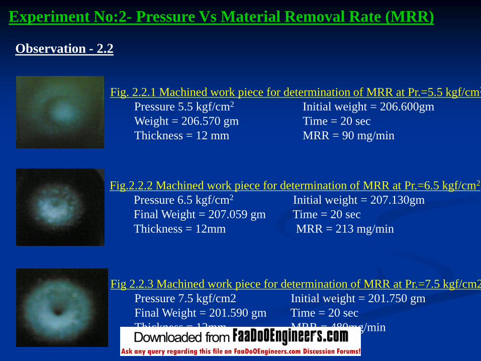
Fig. 2.2.1 Machined work piece for determination of MRR at Pr.=5.5 kgf/cm2
Pressure 5.5 kgf/cm2 Initial weight = 206.600gm
Weight = 206.570 gm Time = 20 sec
Thickness = 12 mm MRR = 90 mg/min
Fig.2.2.2 Machined work piece for determination of MRR at Pr.=6.5 kgf/cm2
Pressure 6.5 kgf/cm2 Initial weight = 207.130gm
Final Weight = 207.059 gm Time = 20 sec
Thickness = 12mm MRR = 213 mg/min
Fig 2.2.3 Machined work piece for determination of MRR at Pr.=7.5 kgf/cm2
Pressure 7.5 kgf/cm2 Initial weight = 201.750 gm
Final Weight = 201.590 gm Time = 20 sec
Thickness = 12mm MRR = 480mg/min
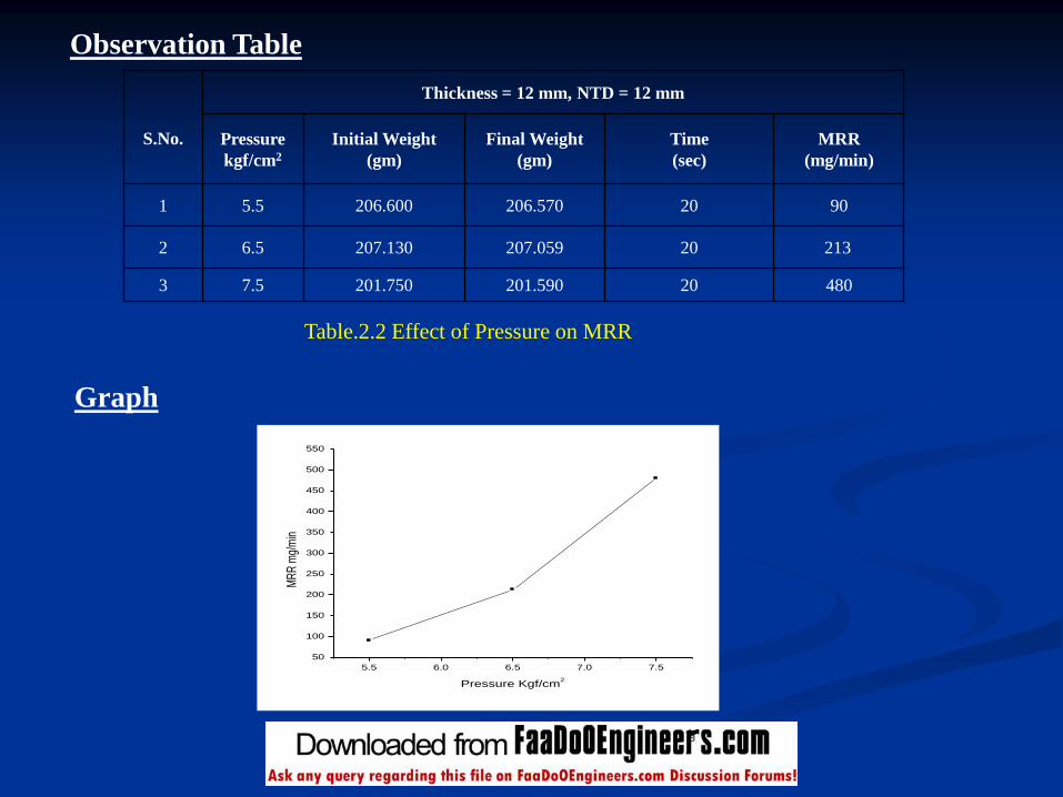
Observation Table
S.No.
Thickness = 12 mm, NTD = 12 mm
Pressure
kgf/cm2
Initial Weight
(gm)
Final Weight
(gm)
Time
(sec)
MRR
(mg/min)
1 5.5 206.600 206.570 20 90
2 6.5 207.130 207.059 20 213
3 7.5 201.750 201.590 20 480
Table.2.2 Effect of Pressure on MRR
Graph
5.5 6.0 6.5 7.0 7.5
50
100
150
200
250
300
350
400
450
500
550
MR
R m
g/m
in
Pressure Kgf/cm2
Fig.2.2.4 Graph of Pressure vs. MRR
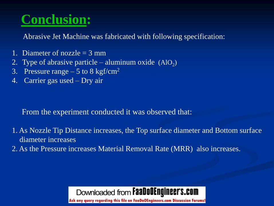
Abrasive Jet Machine was fabricated with following specification:
1. Diameter of nozzle = 3 mm
2. Type of abrasive particle – aluminum oxide (AlO2)
3. Pressure range – 5 to 8 kgf/cm2
4. Carrier gas used – Dry air
From the experiment conducted it was observed that:
1. As Nozzle Tip Distance increases, the Top surface diameter and Bottom surface
diameter increases
2. As the Pressure increases Material Removal Rate (MRR) also increases.
Conclusion:
Scope of Future Work:
In this fabricated abrasive jet unit experiment can be conducted :
1. By using different nozzle tip diameter.
2. By using different type of abrasive particles.
3. By using different sizes of abrasive particles.
4. By using different work material.
5. Also the abrasive jet machine can be improved by retrofitting,
computer numerical control (CNC)
References
M. Roopa Rani and S. Seshan “Abrasive Jet Machining-Process Variables and Current Application”Metals Materials and Process,1995 Vol.7 No.4,pp 279-290.
P K Ray and Dr A K Paul, “Some Studies on Abrasive Jet Machining” Journal of the Institution of Engineers (India) vol 68 part PE 2 November 1987
Alok K.Verma, Cheng Y. Lin Associate Professor ,Engineering Technology Dept. Old Dominion University Norfolk, Virginia “Parametric Study of the Efficacy of Cutting Process in Abrasive Jet Machining (AJM)”
P. C. Pandey & H.S. Shan ,” Modern Machining “ Tata McGraw-Hill Publishing Company , Edition :1980
Production Technology HMT Tata McGraw-Hill Publishing Company , Edition :1980
Maleev & Hartman “Machine Design “edited by O. P. Grover “ CBS Publishing & Distributor
Amitabh Ghosh & Ashok Kumar Malik “Manufacturing Process “East –West Press Private Limited ,New Delhi, Edition 1995

THANKS
Recommended