ABB
Emergency stopsand safety stops
11:1ABB
1
11
2
3
4
5
6
7
8
9
10
13
14
12
Contents Page
Why do you need an Emergency stop? ________________________________11:2
Emergency stop for enclosure installation – INCA 1 ____________________11:3
Emergency stop for enclosure installation – INCA 1 Tina _______________11:4
Emergency stop with LED – Smile ____________________________________11:6
Emergency stop with LED – Smile Tina ______________________________11:10
Emergency stop with LED – Smile AS-i ______________________________11:14
Emergency stop Grab Wire Safety Switch Stop-Line ___________________11:16
Safety stop Inca and Smile ________________________________________ 11:20
Reset button Smile 11R____________________________________________ 11:21
Descriptions and examples in this book show how the products work and can be used. This does not mean that they can meet the requirements for all types of machines and processes. The purchaser/user is responsible for ensuring that the product is installed and used in accordance with the applicable regulations and standards. We reserve the right to make changes in products and product sheets without previous notice. For the latest updates, refer to www.abb.com/lowvoltage. 2011.
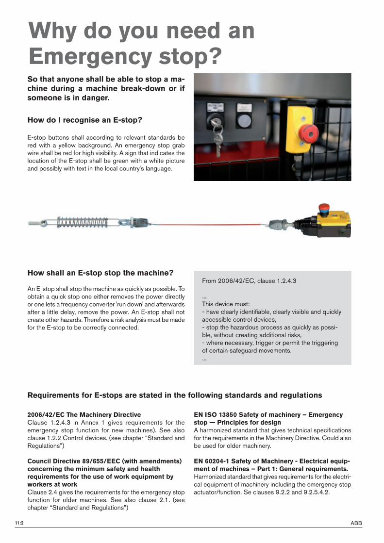
ABB11:2
So that anyone shall be able to stop a ma-chine during a machine break-down or if someone is in danger.
Why do you need an Emergency stop?
How do I recognise an E-stop?
E-stop buttons shall according to relevant standards be red with a yellow background. An emergency stop grab wire shall be red for high visibility. A sign that indicates the location of the E-stop shall be green with a white picture and possibly with text in the local country's language.
How shall an E-stop stop the machine?
An E-stop shall stop the machine as quickly as possible. To obtain a quick stop one either removes the power directly or one lets a frequency converter 'run down' and afterwards after a little delay, remove the power. An E-stop shall not create other hazards. Therefore a risk analysis must be made for the E-stop to be correctly connected.
From 2006/42/EC, clause 1.2.4.3
...This device must:- have clearly identifiable, clearly visible and quickly accessible control devices,- stop the hazardous process as quickly as possi-ble, without creating additional risks,- where necessary, trigger or permit the triggering of certain safeguard movements....
2006/42/EC The Machinery DirectiveClause 1.2.4.3 in Annex 1 gives requirements for the emergency stop function for new machines). See also clause 1.2.2 Control devices. (see chapter “Standard and Regulations”)
Council Directive 89/655/EEC (with amendments) concerning the minimum safety and health requirements for the use of work equipment by workers at workClause 2.4 gives the requirements for the emergency stop function for older machines. See also clause 2.1. (see chapter “Standard and Regulations”)
EN ISO 13850 Safety of machinery – Emergency stop — Principles for designA harmonized standard that gives technical specifications for the requirements in the Machinery Directive. Could also be used for older machinery.
EN 60204-1 Safety of Machinery - Electrical equip-ment of machines – Part 1: General requirements.Harmonized standard that gives requirements for the electri-cal equipment of machinery including the emergency stop actuator/function. Se clauses 9.2.2 and 9.2.5.4.2.
Requirements for E-stops are stated in the following standards and regulations
11:3ABB
!
"
#
$
%
&
'()*+"%
,#
(#$!
-.*" ,*/0123
!
-"-
',#)*+#%+%$
+#$
+"$
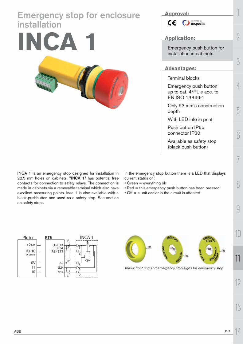
INCA 1(S) Pluto RT6
1
11
2
3
4
5
6
7
8
9
10
13
14
12
CE RTI F I E D BY
INCA 1 is an emergency stop designed for installation in 22.5 mm holes on cabinets. ”INCA 1” has potential free contacts for connection to safety relays. The connection is made in cabinets via a removable terminal which also have excellent measuring points. Inca 1 is also available with a black pushbutton and used as a safety stop. See section on safety stops.
In the emergency stop button there is a LED that displays current status on:• Green = everything ok• Red = this emergency push button has been pressed• Off = a unit earlier in the circuit is affected
Yellow front ring and emergency stop signs for emergency stop.
Approval:
Application:
Emergency push button for installation in cabinets
Advantages:
Terminal blocks
Emergency push button up to cat. 4/PL e acc. to EN ISO 13849-1
Only 53 mm's construction depth
With LED info in print
Push button IP65, connector IP20
Available as safety stop (black push button)
Emergency stop for enclosure installation
INCA 1
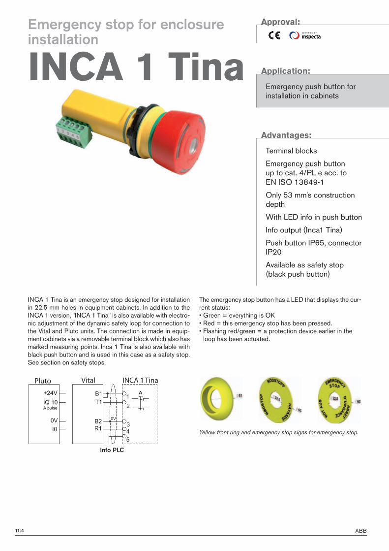
ABB11:4
!
"
#
$%
&
9"
4"
9#
5"
(#$!
-.*" ,*/0123
!
-
Pluto Vital INCA 1(S) TinaINCA 1(S) Tina
Info PLC
CE RTI F I E D BY
INCA 1 Tina is an emergency stop designed for installation in 22.5 mm holes in equipment cabinets. In addition to the INCA 1 version, "INCA 1 Tina" is also available with electro-nic adjustment of the dynamic safety loop for connection to the Vital and Pluto units. The connection is made in equip-ment cabinets via a removable terminal block which also has marked measuring points. Inca 1 Tina is also available with black push button and is used in this case as a safety stop. See section on safety stops.
The emergency stop button has a LED that displays the cur-rent status: • Green = everything is OK• Red = this emergency stop has been pressed. • Flashing red/green = a protection device earlier in the loop has been actuated.
Approval:
Application:
Emergency push button for installation in cabinets
Advantages:
Terminal blocks
Emergency push button up to cat. 4/PL e acc. to EN ISO 13849-1
Only 53 mm's construction depth
With LED info in push button
Info output (Inca1 Tina)
Push button IP65, connector IP20
Available as safety stop (black push button)
Yellow front ring and emergency stop signs for emergency stop.
Emergency stop for enclosure installation
INCA 1 Tina
11:5ABB
1
11
2
3
4
5
6
7
8
9
10
13
14
12
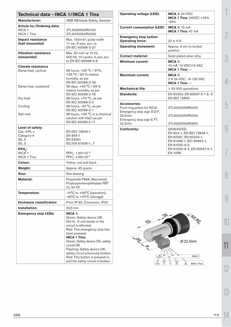
Technical data - INCA 1/INCA 1 TinaManufacturer: ABB AB/Jokab Safety, Sweden
Article no./Ordering data:INCA 1INCA 1 Tina
2TLA030054R01002TLA030054R0000
Impact resistance(half sinusoidal)
Max. 150m/s², pulse width 11 ms, 3-axis, acc. to EN IEC 60068-2-27
Vibration resistance(sinusoidal)
Max. 50 m/s² at 10 Hz…500 Hz, 10 cycles, 3 axis, acc. to EN IEC 60068-2-6
Climate resistanceDamp heat, cyclical
Damp heat, sustained
Dry heat
Cooling
Salt mist
96 hours, +25 °C / 97%, +55 °C / 93 % relative humidity, as per EN IEC 60068-2-3056 days, +40 °C / 93 % relative humidity, as per EN IEC 60068-2-7896 hours, +70 °C, as per EN IEC 60068-2-296 hours, -40 °C, as per EN IEC 60068-2-196 hours, +35 °C in a chemical solution with NaCl as per EN IEC 60068-2-11
Level of safety:Cat. 4/PL eCategory 4SIL 3SIL 3
EN ISO 13849-1EN 954-1EN 62061IEC/EN 61508-1...7
PFHd:
INCA 1INCA 1 Tina:
PFHd: 1,60×10⁻¹⁰
PFHd: 4.66×10⁻⁹
Colour: Yellow, red and black
Weight: Approx. 45 grams
Size: See drawing
Material: Polyamide PA66, Macromelt, Polybutylenterephthalate PBTUL 94 V0
Temperature: -10°C to +55°C (operation), -30°C to +70°C (storage)
Enclosure classification Print: IP 65, Connector: IP20
Installation: 22,5 mm
Emergency stop LEDs: INCA 1: Green: Safety device OK.Not lit: A unit earlier in the circuit is affected.Red: This emergency stop has been pressed.INCA 1 Tina: Green: Safety device OK, safety circuit OKFlashing: Safety device OK, safety circuit previously broken.Red: This button is pressed in, and the safety circuit is broken.
Operating voltage (LED): INCA 1: 24 VDCINCA 1 Tina: 24VDC +15% -25%
Current consumption (LED): INCA 1: 15 mAINCA 1 Tina: 47 mA
Emergency stop buttonOperating force: 22 ± 4 N
Operating movement: Approx. 4 mm to locked position
Contact material: Gold-plated silver alloy
Minimum current: INCA 1: 10 mA, 10 VDC/10 VACINCA 1 Tina: —
Maximum current: INCA 1: 2 A 24 VDC, 1A 125 VACINCA 1 Tina: —
Mechanical life: > 50 000 operations
Standards: EN 60204, EN 60947-5-1 & -5EN ISO 13850
Accessories:Front ring yellow for INCAEmergency stop sign S D F, 22,5mmEmergency stop sign E FT, 22,5mm
2TLA030054R0400
2TLA030054R0500
2TLA030054R0600
Conformity: 2006/42/EGEN 954-1, EN ISO 13849-1, EN 62061, EN 60204-1, EN 61496-1, IEC 60664-1, EN 61000-6-2, EN 61000-6-4, EN 60947-5-1, EN 1088
11:6 ABB
12
5
3
4
6
CE RTI F I E D BY
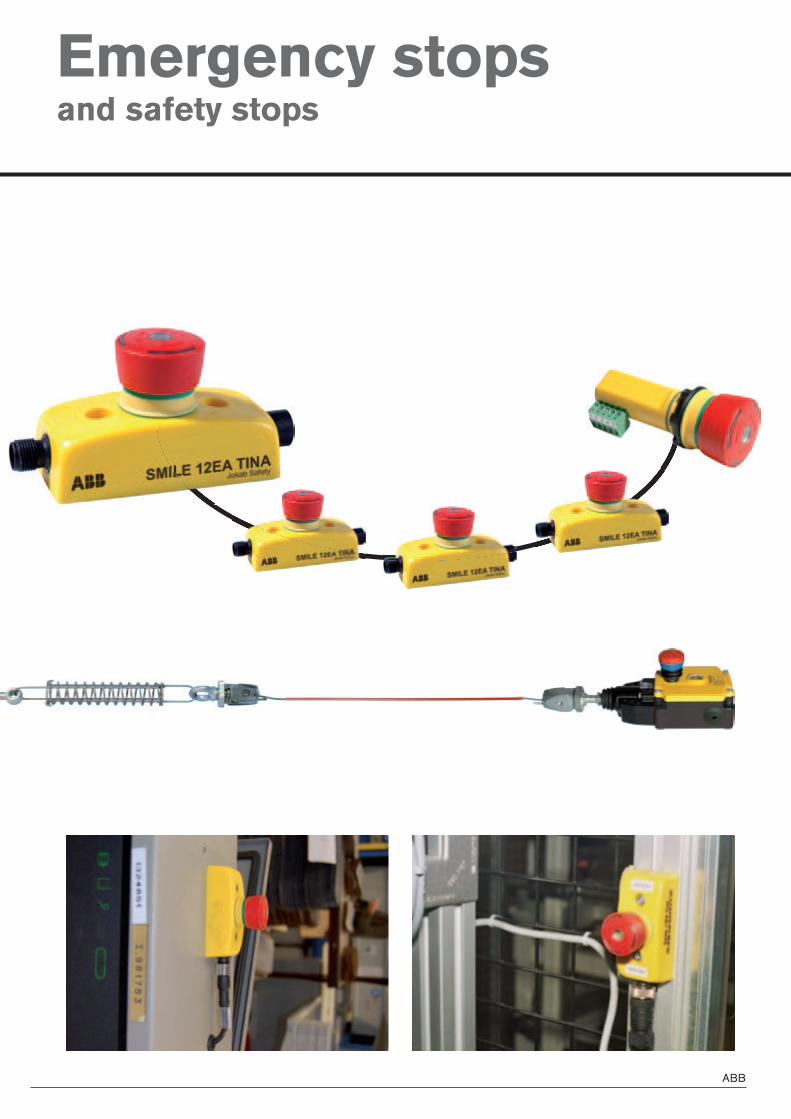
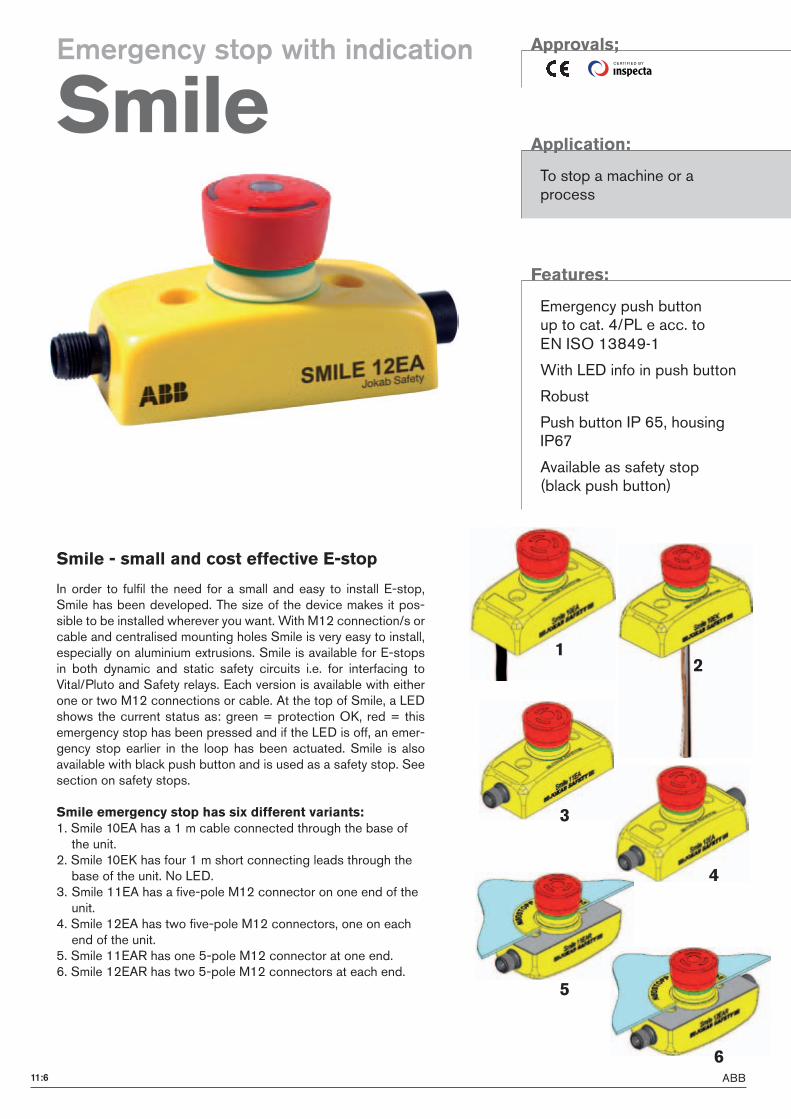
In order to fulfil the need for a small and easy to install E-stop, Smile has been developed. The size of the device makes it pos-sible to be installed wherever you want. With M12 connection/s or cable and centralised mounting holes Smile is very easy to install, especially on aluminium extrusions. Smile is available for E-stops in both dynamic and static safety circuits i.e. for interfacing to Vital/Pluto and Safety relays. Each version is available with either one or two M12 connections or cable. At the top of Smile, a LED shows the current status as: green = protection OK, red = this emergency stop has been pressed and if the LED is off, an emer-gency stop earlier in the loop has been actuated. Smile is also available with black push button and is used as a safety stop. See section on safety stops.
Smile emergency stop has six different variants:1. Smile 10EA has a 1 m cable connected through the base of the unit.2. Smile 10EK has four 1 m short connecting leads through the base of the unit. No LED.3. Smile 11EA has a five-pole M12 connector on one end of the unit. 4. Smile 12EA has two five-pole M12 connectors, one on each end of the unit. 5. Smile 11EAR has one 5-pole M12 connector at one end.6. Smile 12EAR has two 5-pole M12 connectors at each end.
Smile - small and cost effective E-stop
Approvals;
Application:
To stop a machine or a process
Features:
Emergency push button up to cat. 4/PL e acc. to EN ISO 13849-1
With LED info in push button
Robust
Push button IP 65, housing IP67
Available as safety stop (black push button)
Emergency stop with indication
Smile
11:7ABB
1
11
2
3
4
5
6
7
8
9
10
13
14
12
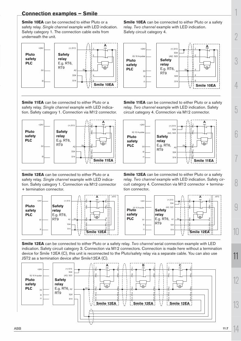
Connection examples – Smile
Smile 10EA can be connected to either Pluto or a safety relay. Single channel example with LED indication.Safety category 1. The connection cable exits from underneath the unit.
Smile 10EA can be connected to either Pluto or a safety relay. Two channel example with LED indication.Safety circuit category 4.
Smile 11EA can be connected to either Pluto or a safety relay. Single channel example with LED indica-tion. Safety category 1. Connection via M12 connector.
Smile 11EA can be connected to either Pluto or a safety relay. Two channel example with LED indication. Safety circuit category 4. Connection via M12 connector.
Smile 12EA can be connected to either Pluto or a safety relay. Single channel example with LED indica-tion. Safety category 1. Connection via M12 connector + termination connector.
Smile 12EA can be connected to either Pluto or a safety relay. Two channel example with LED indication. Safety cir-cuit category 4. Connection via M12 connector + termina-tion connector.
Smile 12EA can be connected to either Pluto or a safety relay. Two channel serial connection example with LED indication. Safety circuit category 3. Connection via M12 connectors. Connection is made here without a termination device for Smile 12EA (C), this unit is reconnected to the Pluto/safety relay via a separate cable. You can also use JST2 as a termination device after Smile12EA (C).
Pluto safety PLC
Pluto safety PLC
Safety relayE.g. RT6, RT9
Safety relayE.g. RT6, RT9
Smile 10EA Smile 10EA
!
"
#
$
%
&
'()*+"%
+"$
+%$
,#
(#$!
!
-
!
"
#
$
%
&
'()*+"%
+"$
+#$
,#
+%$
(#$!
+#%-.*" *,:/0123
!
-
-"
',#)
Pluto safety PLC
Pluto safety PLC
Safety relayE.g. RT6, RT9
Safety relayE.g. RT6, RT9
Smile 11EA Smile 11EA
!
"
#
$
%
&
'()*+"%
+"$
+%$
,#
(#$!
!
-
!
"
#
$
%
&
'()*+"%
+"$
+#$
,#
+%$
(#$!
+#%-.*" *,:/0123
!
-
-"
',#)
Smile 12EA Smile 12EA Smile 12EA
Pluto safety PLC
Safety relayE.g. RT6, RT9
Pluto safety PLC
Pluto safety PLC
Safety relayE.g. RT6, RT9
Safety relayE.g. RT6, RT9
Smile 12EA Smile 12EA
!
'()*+"%
+"$
+#$
,#
+%$
(#$!
+#%-.*" *,:/0123
!
-
-"
"
#
$
%
&
"
#
$
%
&
!
'()*+"%
+"$
+%$
,#
(#$!
!
-
"
#
$
%
&
"
#
$
%
&
',#)
<+5#<+5#
"
#
$
%
&
"
#
$
%
&
!
"
#
$
%
&
"
#
$
%
&
"
#
$
%
&
"
#
$
%
&
'()*+"%
+"$
+#$
,#
+%$
(#$!
+#%-.*" *,:/0123
!
-
-"
"
',#)
!
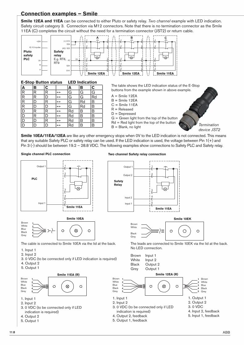
ABB11:8
Connection examples – Smile
Smile 12EA and 11EA can be connected to either Pluto or safety relay. Two channel example with LED indication.Safety circuit category 3. Connection via M12 connectors. Note that there is no termination connector as the Smile 11EA (C) completes the circuit without the need for a termination connector (JST2) or return cable.
The table shows the LED indication status of the E-Stop buttons from the example shown in above example.
A = Smile 12EAB = Smile 12EA C = Smile 11EAR = ReleasedD = DepressedG = Green light from the top of the buttonRd = Red light from the top of the buttonB = Blank, no light
E-Stop Button status LED Indication
Smile 10EA/11EA/12EA are like any other emergency stops when 0V to the LED indication is not connected. This means that any suitable Safety PLC or safety relay can be used. If the LED indication is used, the voltage between Pin 1(+) and Pin 3 (-) should be between 19.2 – 28.8 VDC. The following examples show connections to Safety PLC and Safety relay.
The cable is connected to Smile 10EA via the lid at the back.
1. Input 1 2. Input 2 3. 0 VDC (to be connected only if LED indication is required)4. Output 25. Output 1
1. Input 1 2. Input 23. 0 VDC (to be connected only if LED indication is required)4. Output 25. Output 1
1. Output 12. Output 23. 0 VDC4. Input 2, feedback5. Input 1, feedback
1. Input 1 2. Input 2 3. 0 VDC (to be connected only if LED indication is required)4. Output 2, feedback5. Output 1, feedback
Brown Input 1 White Input 2 Black Output 2Grey Output 1
The leads are connected to Smile 10EK via the lid at the back.No LED connection.
Pluto safety PLC
Safety relayE.g. RT6, RT9
Smile 12EA Smile 12EA Smile 11EA
"
#
$
%
&
"
#
$
%
&
"
#
$
%
&
!
+"$
+#$
"
#
$
%
&
"
#
$
%
&
!"'()*+"%
,#
+%$
(#$!
+#%-.*" *,:/0123
!
-
-"
',#)
Two channel Safety relay connection
SafetyRelay
Smile 11EA
"
#
$
%
&
=0>/0>*"
-6/0>*"
-6/0>*#
=0>/0>*#
Single channel PLC connection
PLC
Smile 11EA
"
#
$
%
&
=0>/0>*"
-6/0>*"
BrownWhiteBlueBlackGrey
BrownWhiteBlueBlackGrey
Smile 12EA (R)
#
$
%
&
'
#
$
%
&
'
BrownWhiteBlueBlackGrey
Smile 10EA
#
$
%
&
'
BrownWhiteBlueBlackGrey
Smile 11EA (R)
#
$
%
&
'
BrownWhite
BlackGrey
Smile 10EK
A B C A B CR R R G G GR R D G G RdR D R G Rd BR D D G Rd BD R R Rd B BD R D Rd B BD D R Rd B BD D D Rd B B Termination
device JST2
11:9ABB
1
11
2
3
4
5
6
7
8
9
10
13
14
12
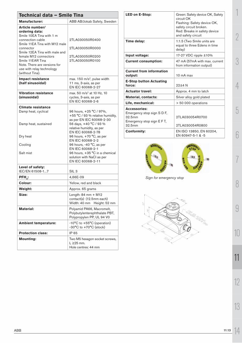
Sign for emergency stop
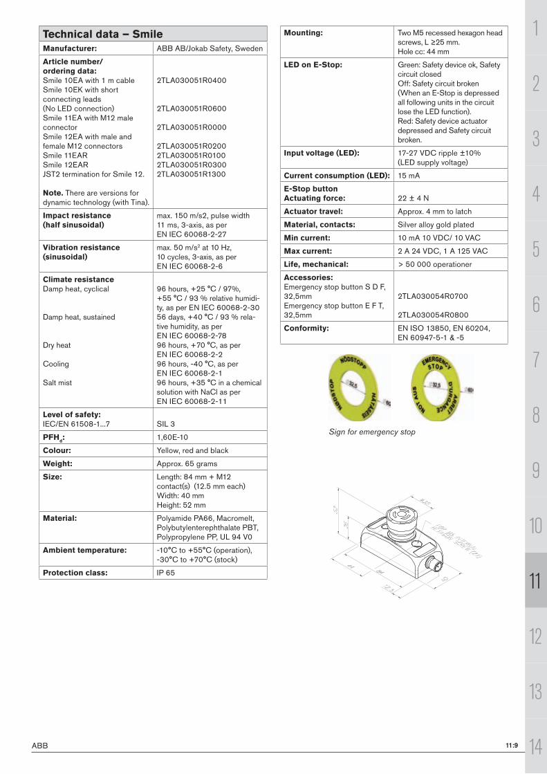
Technical data – SmileManufacturer: ABB AB/Jokab Safety, Sweden
Article number/ ordering data:Smile 10EA with 1 m cableSmile 10EK with short connecting leads (No LED connection)Smile 11EA with M12 male connectorSmile 12EA with male and female M12 connectorsSmile 11EAR Smile 12EARJST2 termination for Smile 12.
Note. There are versions for dynamic technology (with Tina).
2TLA030051R0400
2TLA030051R0600
2TLA030051R0000
2TLA030051R02002TLA030051R01002TLA030051R03002TLA030051R1300
Impact resistance (half sinusoidal)
max. 150 m/s2, pulse width 11 ms, 3-axis, as per EN IEC 60068-2-27
Vibration resistance (sinusoidal)
max. 50 m/s2 at 10 Hz, 10 cycles, 3-axis, as per EN IEC 60068-2-6
Climate resistanceDamp heat, cyclical
Damp heat, sustained
Dry heat
Cooling
Salt mist
96 hours, +25 °C / 97%, +55 °C / 93 % relative humidi-ty, as per EN IEC 60068-2-3056 days, +40 °C / 93 % rela-tive humidity, as per EN IEC 60068-2-7896 hours, +70 °C, as per EN IEC 60068-2-296 hours, -40 °C, as per EN IEC 60068-2-196 hours, +35 °C in a chemical solution with NaCl as per EN IEC 60068-2-11
Level of safety:IEC/EN 61508-1...7 SIL 3
PFHd: 1,60E-10
Colour: Yellow, red and black
Weight: Approx. 65 grams
Size: Length: 84 mm + M12 contact(s) (12.5 mm each)Width: 40 mmHeight: 52 mm
Material: Polyamide PA66, Macromelt, Polybutylentere phthalate PBT, Polypropylene PP, UL 94 V0
Ambient temperature: -10°C to +55°C (operation), -30°C to +70°C (stock)
Protection class: IP 65
Mounting: Two M5 recessed hexagon head screws, L ≥25 mm. Hole cc: 44 mm
LED on E-Stop: Green: Safety device ok, Safety circuit closedOff: Safety circuit broken (When an E-Stop is depressed all following units in the circuit lose the LED function).Red: Safety device actuator depressed and Safety circuit broken.
Input voltage (LED): 17-27 VDC ripple ±10% (LED supply voltage)
Current consumption (LED): 15 mA
E-Stop buttonActuating force: 22 ± 4 N
Actuator travel: Approx. 4 mm to latch
Material, contacts: Silver alloy gold plated
Min current: 10 mA 10 VDC/ 10 VAC
Max current: 2 A 24 VDC, 1 A 125 VAC
Life, mechanical: > 50 000 operationer
Accessories:Emergency stop button S D F, 32,5mmEmergency stop button E F T, 32,5mm
2TLA030054R0700
2TLA030054R0800
Conformity: EN ISO 13850, EN 60204, EN 60947-5-1 & -5
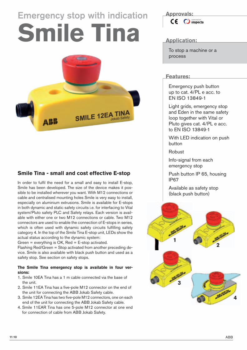
ABB11:10
12
3
4
CE RTI F I E D BY
In order to fulfil the need for a small and easy to install E-stop, Smile has been developed. The size of the device makes it pos-sible to be installed wherever you want. With M12 connections or cable and centralised mounting holes Smile is very easy to install, especially on aluminium extrusions. Smile is available for E-stops in both dynamic and static safety circuits i.e. for interfacing to Vital system/Pluto safety PLC and Safety relays. Each version is avail-able with either one or two M12 connections or cable. Two M12 connectors are used to enable the connection of E-stops in series, which is often used with dynamic safety circuits fulfilling safety category 4. In the top of the Smile Tina E-stop unit, LEDs show the actual status according to the dynamic system: Green = everything is OK, Red = E-stop activated. Flashing Red/Green = Stop activated from another preceding de-vice. Smile is also available with black push button and used as a safety stop. See section on safety stops.
The Smile Tina emergency stop is available in four ver-sions:1. Smile 10EA Tina has a 1 m cable connected via the base of the unit.2. Smile 11EA Tina has a five-pole M12 connector on the end of the unit for connecting the ABB Jokab Safety cable.3. Smile 12EA Tina has two five-pole M12 connectors, one on each end of the unit for connecting the ABB Jokab Safety cable.
4. Smile 11EAR Tina has one 5-pole M12 connector at one end for connection of cable from ABB Jokab Safety.
Smile Tina - small and cost effective E-stop
Approvals:
Application:
To stop a machine or a process
Features:
Emergency push button up to cat. 4/PL e acc. to EN ISO 13849-1
Light grids, emergency stop and Eden in the same safety loop together with Vital or Pluto gives cat. 4/PL e acc. to EN ISO 13849-1
With LED indication on push button
Robust
Info-signal from each emergency stop
Push button IP 65, housing IP67
Available as safety stop (black push button)
Emergency stop with indication
Smile Tina
11:11ABB
Pluto Vital
Smile 10EA Tina
Smile 11EA Tina
Smile 11EA Tina
Smile 11EA Tina
Pluto Vital
Smile 11EA Tina
Smile 11EA Tina
Smile 11EA Tina
Pluto Vital Tina 4A
Eden = Adam & Eva
"
!
(
)
*+#,
*,
(
)
*+#,
*,
%
$
#
&
(
)
*+#,
*,
!
"
1
11
2
3
4
5
6
7
8
9
10
13
14
12
Connection examples – Smile Tina
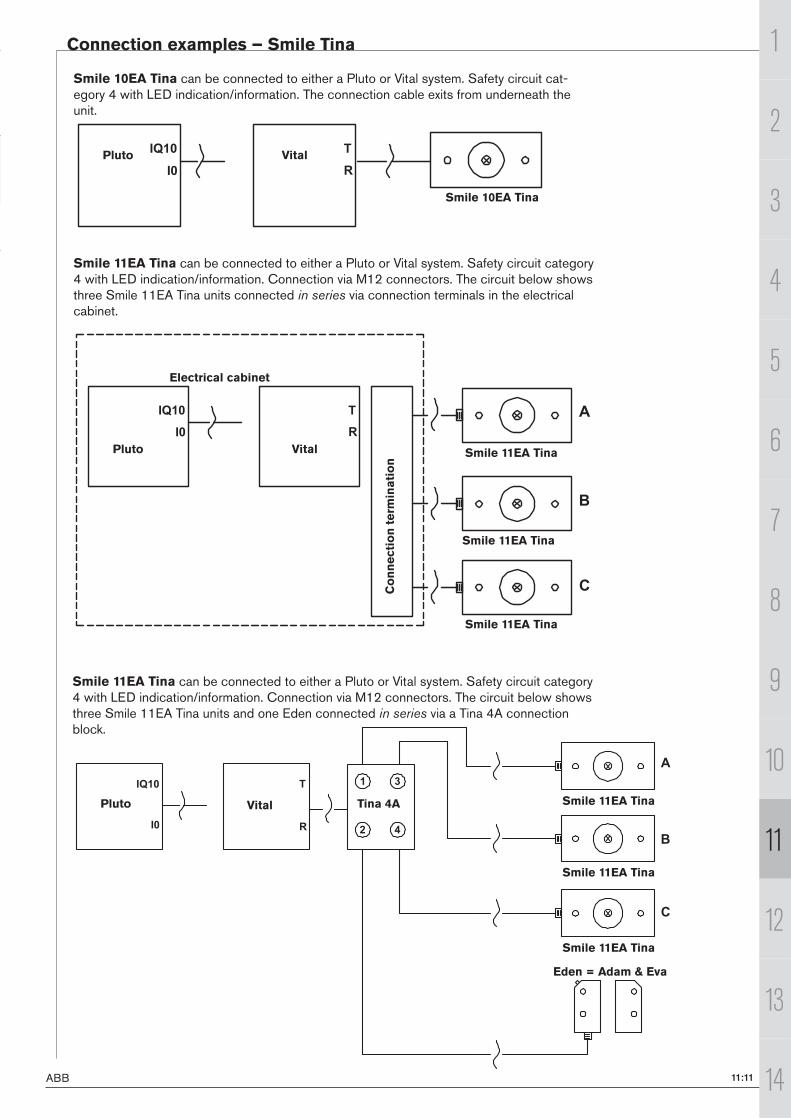
Smile 10EA Tina can be connected to either a Pluto or Vital system. Safety circuit cat-egory 4 with LED indication/information. The connection cable exits from underneath the unit.
Smile 11EA Tina can be connected to either a Pluto or Vital system. Safety circuit category 4 with LED indication/information. Connection via M12 connectors. The circuit below shows three Smile 11EA Tina units connected in series via connection terminals in the electrical cabinet.
Smile 11EA Tina can be connected to either a Pluto or Vital system. Safety circuit category 4 with LED indication/information. Connection via M12 connectors. The circuit below shows three Smile 11EA Tina units and one Eden connected in series via a Tina 4A connection block.
Electrical cabinetC
onnecti
on term
inati
on
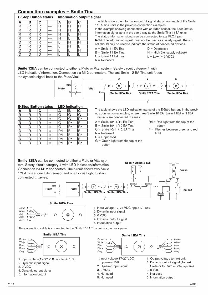
ABB11:12
Pluto Vital
Smile 12EA Tina Smile 12EA Tina
Eden = Adam & Eva
Tina 10A
Focus
?"#:%, ?"#:%,
?"#:%9
(
)
*+#,
*,
Pluto Vital
Smile 12EA Tina Smile 12EA TinaSmile 12EA Tina
" !
(
)
*+#,
*,
Connection examples – Smile Tina
The connection cable is connected to the Smile 10EA Tina unit via the back panel.
1. Input voltage,17-27 VDC ripple+/- 10%2. Dynamic input signal3. 0 VDC4. Dynamic output signal5. Information output
1. Input voltage,17-27 VDC ripple+/- 10%2. Dynamic input signal3. 0 VDC4. Dynamic output signal5. Information output
1. Input voltage,17-27 VDC ripple+/- 10%2. Dynamic input signal3. 0 VDC4. Not used5. Not used
1. Output voltage to next unit2. Dynamic output signal (To next Smile or to Pluto or Vital system)3. 0 VDC4. Not used5. Information output
Smile 12EA can be connected to either a Pluto or Vital system. Safety circuit category 4 with LED indication/information. Connection via M12 connectors. The last Smile 12 EA Tina unit feeds the dynamic signal back to the Pluto/Vital.
The table shows the LED indication status of the E-Stop buttons in the previ-ous connection examples, where three Smile 10 EA, Smile 11EA or 12EA Tina units are connected in series.
A = Smile 10/11/12 EA TinaB = Smile 10/11/12 EA TinaC = Smile 10/11/12 EA TinaR = ReleasedD = DepressedG = Green light from the top of the
button
Rd = Red light from the top of the button
F = Flashes between green and red light
E-Stop Button status LED Indication
The table shows the information output signal status from each of the Smile 11EA Tina units in the previous connection examples.In the example showing connection with an Eden sensor, the Eden status information signal acts in the same way as the Smile Tina 11EA units.The status information signal can be connected to e.g. PLC input.Note. The information signal must not be used as a safety signal. The sig-nal should only be used to indicate the status of connected devices.
A = Smile 11 EA TinaB = Smile 11 EA TinaC = Smile 11 EA TinaR = Released
D = DepressedH = High (i.e. supply voltage)L = Low (= 0 VDC)
E-Stop Button status Information output signal
Smile 12EA can be connected to either a Pluto or Vital sys-tem. Safety circuit category 4 with LED indication/information. Connection via M12 connectors. The circuit shows two Smile 12EA Tina’s, one Eden sensor and one Focus Light Curtain connected in series.
A B C A B CR R R G G GR R D G G RdR D R G Rd FR D D G Rd RdD R R Rd F FD R D Rd F RdD D R Rd Rd FD D D Rd Rd Rd
A B C A B CR R R H H HR R D H H LR R R H L HR R D H L LD R R L H HD R D L H LD D R L L HD D D L L L
BrownWhiteBlueBlackGrey
Smile 11EA Tina
#
$
-
% .
&
'
BrownWhiteBlueBlackGrey
BrownWhiteBlueBlackGrey
Smile 12EA Tina
#
$
-
% .
&
'
-
.
#
$
%
&
'
BrownWhiteBlueBlackGrey
#
$
-
% .
&
'
Smile 10EA Tina
11:13ABB
1
11
2
3
4
5
6
7
8
9
10
13
14
12
Sign for emergency stop
Technical data – Smile TinaManufacturer: ABB AB/Jokab Safety, Sweden
Article number/ ordering data:Smile 10EA Tina with 1 m connection cableSmile 11EA Tina with M12 male connectorSmile 12EA Tina with male and female M12 connectorsSmile 11EAR TinaNote. There are versions for use with relay technology (without Tina).
2TLA030050R0400
2TLA030050R0000
2TLA030050R02002TLA030050R0100
Impact resistance (half sinusoidal)
max. 150 m/s2, pulse width 11 ms, 3-axis, as per EN IEC 60068-2-27
Vibration resistance (sinusoidal)
max. 50 m/s2 at 10 Hz, 10 cycles, 3-axis, as per EN IEC 60068-2-6
Climate resistanceDamp heat, cyclical
Damp heat, sustained
Dry heat
Cooling
Salt mist
96 hours, +25 °C / 97%, +55 °C / 93 % relative humidity, as per EN IEC 60068-2-3056 days, +40 °C / 93 % relative humidity, as per EN IEC 60068-2-7896 hours, +70 °C, as per EN IEC 60068-2-296 hours, -40 °C, as per EN IEC 60068-2-196 hours, +35 °C in a chemical solution with NaCl as per EN IEC 60068-2-11
Level of safety:IEC/EN 61508-1...7 SIL 3
PFHd: 4,66E-09
Colour: Yellow, red and black
Weight: Approx. 65 grams
Size: Length: 84 mm + M12 contact(s) (12.5mm each)Width: 40 mm Height: 52 mm
Material: Polyamid PA66, Macromelt, Polybutylenterephthalate PBT, Polypropylen PP, UL 94 V0
Ambient temperature: -10°C to +55°C (operation) -30°C to +70°C (stock)
Protection class: IP 65
Mounting: Two M5 hexagon socket screws, L ≥25 mm. Hole centres: 44 mm
LED on E-Stop: Green: Safety device OK, Safety circuit OKFlashing: Safety device OK, safety circuit broken.Red: Breaks in safety device and safety circuit
Time delay: 1:1.5 (Two Smile units are equal to three Edens in time delay)
Input voltage: 17-27 VDC ripple ±10%
Current consumption: 47 mA (57mA with max. current from information output)
Current from information output: 10 mA max
E-Stop button Actuating force: 22±4 N
Actuator travel: Approx. 4 mm to latch
Material, contacts: Silver alloy gold plated
Life, mechanical: > 50 000 operations
Accessories:Emergency stop sign S D F, 32.5mmEmergency stop sign E F T, 32.5mm
2TLA030054R0700
2TLA030054R0800
Conformity: EN ISO 13850, EN 60204, EN 60947-5-1 & -5
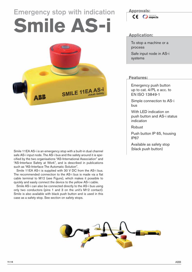
ABB11:14
CE RTI F I E D BY
Smile 11EA AS-i is an emergency stop with a built-in dual channel safe AS-i input node. The AS-i bus and the safety around it is spe-cified by the two organisations “AS-International Association” and “AS-Interface Safety at Work”, and is described in publications such as “AS-Interface The Automatic Solution”.Smile 11EA AS-i is supplied with 30 V DC from the AS-i bus.
The recommended connection to the AS-i bus is made via a flat cable terminal to M12 (see Figure), which makes it possible to quickly and easily connect the device to the yellow AS-i cable.Smile AS-i can also be connected directly to the AS-i bus using
only two conductors (pins 1 and 3 on the unit's M12 contact). Smile is also available with black push button and is used in this case as a safety stop. See section on safety stops.
Approvals:
Application:
To stop a machine or a process
Safe input node in AS-i systems
Features:
Emergency push button up to cat. 4/PL e acc. to EN ISO 13849-1
Simple connection to AS-i bus
With LED indication on push button and AS-i status indication
Robust
Push button IP 65, housing IP67
Available as safety stop (black push button)
Emergency stop with indication
Smile AS-i
11:15ABB
1
11
2
3
4
5
6
7
8
9
10
13
14
12
LED in emergency stop buttonLED displays can be individually programmed in the PLC program as shown below.
LED in push-button
Indicator Description
Red ON Output bit 1 ON
OFF Output bit 1 OFF or Output bit 1 & 2 ON
Green ON Output bit 2 ON
OFF Output bit 2 OFF or Output bit 1 & 2 ON
AS-i LED and Fault LED in combinationLED pair at the M12 contact.
AS-i (Green) Fault (Red)
OFF OFF AS-i voltage missing
ON OFF Normal operation
ON ON No data exchange with master
Flash ON No data exchange due to address = 0
Technical data – Smile AS-iManufacturer: ABB AB/Jokab Safety, Sweden
Article number/ ordering data:Smile 11EA AS-i 2TLA030052R0000
AS-i dataAS-i profile S-7.B.0Addressing M12-contactNode address on delivery 0Response time across the AS-i bus
5 ms (+ response time for safety monitor)
Pin configuration(1) AS-i +(2) Not used(3) AS-i –(4) Not used(5) Not used
Voltage supplyOutput voltage 30 V DC from the AS-i bus.
Tolerance 26.5 – 31.6 V DC.Total current consumption < 60 mA
GeneralEnclosure protection class IP65Ambient temperature -25…+50°CDimensions 52 x 40 x 84 (+12,5 mm M12
contact) (H x B x D)Colour Base: Yellow
Emergency stop button (Smile 11EA AS-i): RedSafe stop button (Smile 11SA AS-i): Black
Actuating force 22 ±4 NActuating movement Ca 4 mm till låsMechanical life > 50 000 operationer
PFHd
6,95x10⁻⁹
Safety/Harmonised standardsIEC/EN 61508-1..7 SIL3, PFDavr: 2,95x10⁻⁵ EN 62061 SIL3EN ISO 13849-1 Performance level PL e,
Category 4, MTTFd: high
EN 60947-5-1 & -5 For emergency stop buttons/safety stop buttons
EN ISO 13850:2008 For emergency stop buttons/safety stop buttons
Certification TÜV Nord
Smile 41xxxx-xwith one AS-i node for four pushbuttons.
Smile 41Exxxx-xwith one AS-i safety node for e-stop and one AS-i node for three pushbuttons.
Smile 41EKxxxx-xwith two safety nodes (e-stop and mode selector) and one AS-i node for two pushbuttons.
Push button control panel
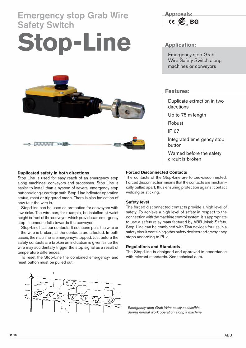
ABB11:16
Emergency-stop Grab Wire easily accessible
during normal work operation along a machine
Duplicated safety in both directionsStop-Line is used for easy reach of an emergency stop along machines, conveyors and processes. Stop-Line is easier to install than a system of several emergency stop buttons along a carriage path. Stop-Line indicates operation status, reset or triggered mode. There is also indication of how taut the wire is.Stop-Line can be used as protection for conveyors with
low risks. The wire can, for example, be installed at waist height in front of the conveyor, which provides an emergency stop if someone falls towards the conveyor.Stop-Line has four contacts. If someone pulls the wire or
if the wire is broken, all the contacts are affected. In both cases, the machine is emergency-stopped. Just before the safety contacts are broken an indication is given since the wire may accidentally trigger the stop signal as a result of temperature differences.To reset the Stop-Line the combined emergency- and
reset button must be pulled out.
Forced Disconnected ContactsThe contacts of the Stop-Line are forced-disconnected. Forced disconnection means that the contacts are mechani-cally pulled apart, thus ensuring protection against contact welding or sticking.
Safety levelThe forced disconnected contacts provide a high level of safety. To achieve a high level of safety in respect to the connection with the machine control system, it is appropriate to use a safety relay manufactured by ABB Jokab Safety. Stop-Line can be combined with Tina devices for use in a safety circuit containing other safety devices and emergency stops according to PL e.
Regulations and StandardsThe Stop-Line is designed and approved in accordance with relevant standards. See technical data.
Approvals:
BG
Application:
Emergency stop Grab Wire Safety Switch along machines or conveyors
Features:
Duplicate extraction in two directions
Up to 75 m length
Robust
IP 67
Integrated emergency stop button
Warned before the safety circuit is broken
Emergency stop Grab WireSafety Switch
Stop-Line
11:17ABB
1
11
2
3
4
5
6
7
8
9
10
13
14
12
The wire should be mounted at least 20 mm from the underlying surface. If the wire is longer than 25 m it must be supported with low friction supports. The ambient temperature during installation should be the same as during operation. For the Stop-Line type A.. After installation, pull the wire strongly several times and then adjust the tension to compensate for any extensions due to de-formation of the thimbles.
Mounting – Stop-Line
Stop-Line 37A/75A
Support
Pull rope spring
Support(Pulley block or Eye bolt)
0,15m
2-5m
0,2m
Max 37m/75m
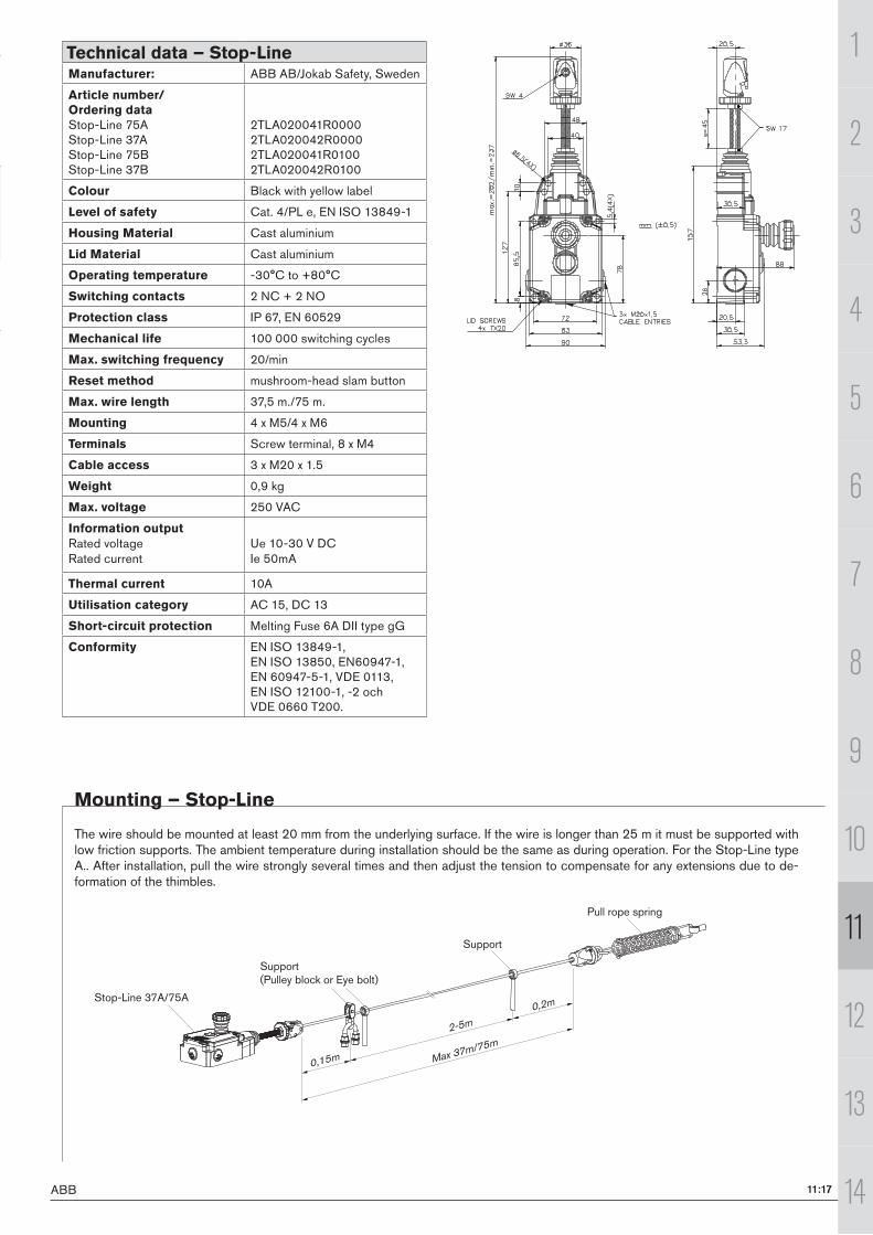
Technical data – Stop-LineManufacturer: ABB AB/Jokab Safety, Sweden
Article number/ Ordering dataStop-Line 75AStop-Line 37AStop-Line 75BStop-Line 37B
2TLA020041R00002TLA020042R00002TLA020041R01002TLA020042R0100
Colour Black with yellow label
Level of safety Cat. 4/PL e, EN ISO 13849-1
Housing Material Cast aluminium
Lid Material Cast aluminium
Operating temperature -30°C to +80°C
Switching contacts 2 NC + 2 NO
Protection class IP 67, EN 60529
Mechanical life 100 000 switching cycles
Max. switching frequency 20/min
Reset method mushroom-head slam button
Max. wire length 37,5 m./75 m.
Mounting 4 x M5/4 x M6
Terminals Screw terminal, 8 x M4
Cable access 3 x M20 x 1.5
Weight 0,9 kg
Max. voltage 250 VAC
Information outputRated voltage Ue 10-30 V DCRated current Ie 50mA
Thermal current 10A
Utilisation category AC 15, DC 13
Short-circuit protection Melting Fuse 6A DII type gG
Conformity EN ISO 13849-1, EN ISO 13850, EN60947-1, EN 60947-5-1, VDE 0113, EN ISO 12100-1, -2 och VDE 0660 T200.
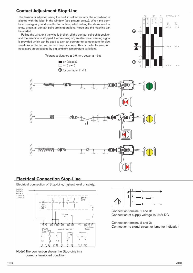
ABB11:18
S
Contact Adjustment Stop-Line
The tension is adjusted using the built-in set screw until the arrowhead is aligned with the label in the window (see picture below). When the com-bined emergency- and reset button is then pulled making the status window show green, all contact pairs are in operational mode and the machine can be started.Pulling the wire, or if the wire is broken, all the contact pairs shift position
and the machine is stopped. Before doing so, an electronic warning signal is provided which can be used to alert an operator to compensate for slow variations of the tension in the Stop-Line wire. This is useful to avoid un-necessary stops caused by e.g. ambient temperature variations.
Electrical connection of Stop-Line, highest level of safety.
Tolerance: distance ± 0.5 mm, power ± 15%
on (closed)off (open)
for contacts 11-12
Note! The connection shows the Stop-Line in a correctly tensioned condition.
Electrical Connection Stop-Line
Connection terminal 1 and 3: Connection of supply voltage 10-30V DC
Connection terminal 2 and 3: Connection to signal circuit or lamp for indication
"*
#*
%*
11:19ABB
1
11
2
3
4
5
6
7
8
9
10
13
14
12
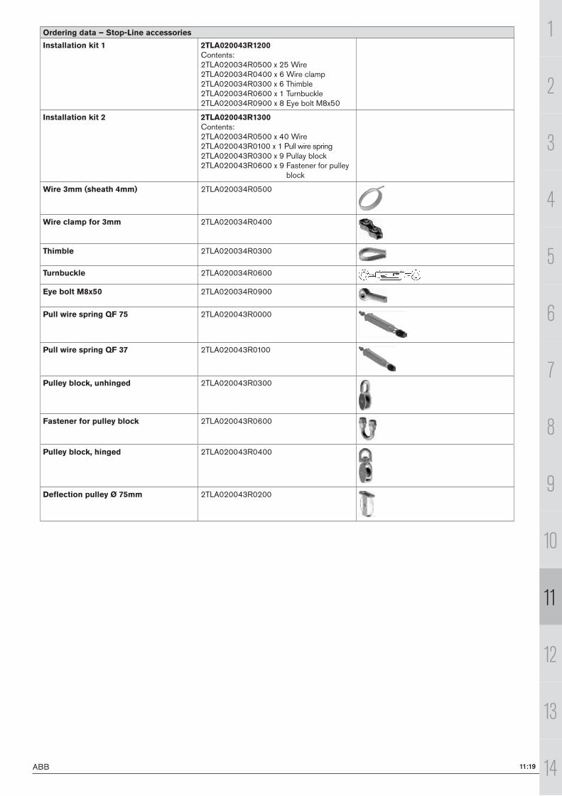
Ordering data – Stop-Line accessories
Installation kit 1 2TLA020043R1200Contents:2TLA020034R0500 x 25 Wire2TLA020034R0400 x 6 Wire clamp2TLA020034R0300 x 6 Thimble2TLA020034R0600 x 1 Turnbuckle2TLA020034R0900 x 8 Eye bolt M8x50
Installation kit 2 2TLA020043R1300Contents:2TLA020034R0500 x 40 Wire2TLA020043R0100 x 1 Pull wire spring2TLA020043R0300 x 9 Pullay block2TLA020043R0600 x 9 Fastener for pulley
block
Wire 3mm (sheath 4mm) 2TLA020034R0500
Wire clamp for 3mm 2TLA020034R0400
Thimble 2TLA020034R0300
Turnbuckle 2TLA020034R0600
Eye bolt M8x50 2TLA020034R0900
Pull wire spring QF 75 2TLA020043R0000
Pull wire spring QF 37 2TLA020043R0100
Pulley block, unhinged 2TLA020043R0300
Fastener for pulley block 2TLA020043R0600
Pulley block, hinged 2TLA020043R0400
Deflection pulley Ø 75mm 2TLA020043R0200
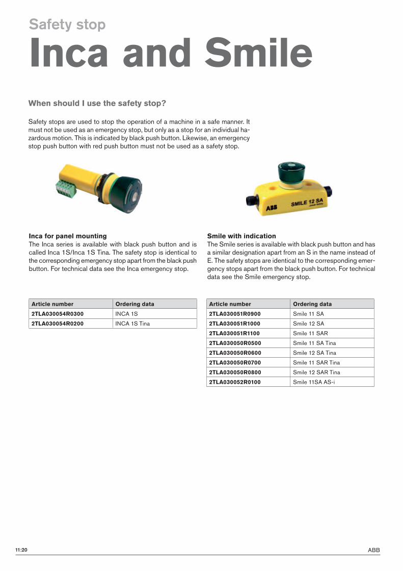
ABB11:20
Article number Ordering data
2TLA030051R0900 Smile 11 SA
2TLA030051R1000 Smile 12 SA
2TLA030051R1100 Smile 11 SAR
2TLA030050R0500 Smile 11 SA Tina
2TLA030050R0600 Smile 12 SA Tina
2TLA030050R0700 Smile 11 SAR Tina
2TLA030050R0800 Smile 12 SAR Tina
2TLA030052R0100 Smile 11SA AS-i
Inca for panel mountingThe Inca series is available with black push button and is called Inca 1S/Inca 1S Tina. The safety stop is identical to the corresponding emergency stop apart from the black push button. For technical data see the Inca emergency stop.
When should I use the safety stop?
Safety stops are used to stop the operation of a machine in a safe manner. It must not be used as an emergency stop, but only as a stop for an individual ha-zardous motion. This is indicated by black push button. Likewise, an emergency stop push button with red push button must not be used as a safety stop.
Smile with indicationThe Smile series is available with black push button and has a similar designation apart from an S in the name instead of E. The safety stops are identical to the corresponding emer-gency stops apart from the black push button. For technical data see the Smile emergency stop.
Article number Ordering data
2TLA030054R0300 INCA 1S
2TLA030054R0200 INCA 1S Tina
Safety stop
Inca and Smile
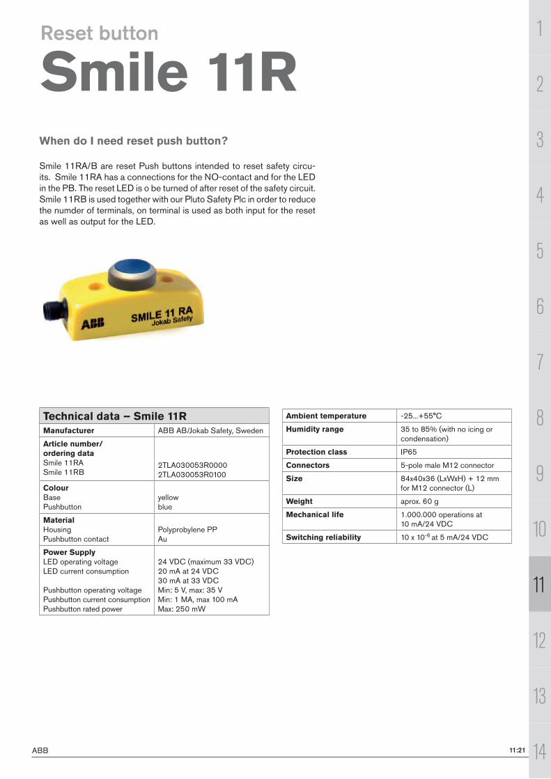
ABB 11:21
1
11
2
3
4
5
6
7
8
9
10
13
14
12
When do I need reset push button?
Smile 11RA/B are reset Push buttons intended to reset safety circu-its. Smile 11RA has a connections for the NO-contact and for the LED in the PB. The reset LED is o be turned of after reset of the safety circuit. Smile 11RB is used together with our Pluto Safety Plc in order to reduce the numder of terminals, on terminal is used as both input for the reset as well as output for the LED.
Reset button
Smile 11R
Technical data – Smile 11RManufacturer ABB AB/Jokab Safety, Sweden
Article number/ ordering dataSmile 11RASmile 11RB
2TLA030053R00002TLA030053R0100
ColourBasePushbutton
yellowblue
MaterialHousingPushbutton contact
Polyprobylene PPAu
Power SupplyLED operating voltageLED current consumption
Pushbutton operating voltagePushbutton current consumptionPushbutton rated power
24 VDC (maximum 33 VDC)20 mA at 24 VDC30 mA at 33 VDCMin: 5 V, max: 35 VMin: 1 MA, max 100 mAMax: 250 mW
Ambient temperature -25...+55°C
Humidity range 35 to 85% (with no icing or condensation)
Protection class IP65
Connectors 5-pole male M12 connector
Size 84x40x36 (LxWxH) + 12 mm for M12 connector (L)
Weight aprox. 60 g
Mechanical life 1.000.000 operations at 10 mA/24 VDC
Switching reliability 10 x 10-6 at 5 mA/24 VDC
Recommended