
HARDWARE MANUAL
A953 HANDY GOT
TARGET MODELS (FOR RS-232C CONNECTION)A953GOT-LBD-M3-HA953GOT-SBD-M3-H
Foreword
• This manual contains text, diagrams and explanations which will guide the reader in thecorrect installation and operation of the GOT-A900. It should be read and understood beforeattempting to install or use the unit.
• Further information can be found in the GOT-900 Series Operating Manual (IntroductoryManual), GOT-A900 Series Operating Manual, GOT-A900 Series User’s Manual
• If in doubt at any stage of the installation of GOT-A900 always consult a professionalelectrical engineer who is qualified and trained to the local and national standards whichapply to the installation site.
• If in doubt about the operation or use of GOT-A900 please consult the nearest MitsubishiElectric distributor.
• This manual is subject to change without notice.
A953 HANDY GOT
A953 HANDY GOT
HARDWARE MANUAL
Manual number : JY992D99801
Manual revision : C
Date : September 2008
A953 HANDY GOT
i

A953 HANDY GOT
ii
FAX BACK
Mitsubishi has a world wide reputation for its efforts in continually developing and pushing backthe frontiers of industrial automation. What is sometimes overlooked by the user is the careand attention to detail that is taken with the documentation. However, to continue this processof improvement, the comments of the Mitsubishi users are always welcomed. This page hasbeen designed for you, the reader, to fill in your comments and fax them back to us. We lookforward to hearing from you.
Fax numbers: Your name: ...................................................
Mitsubishi Electric.... .....................................................................
America (01) 847-478-2253 Your company: .............................................
Australia (02) 638-7072 .....................................................................
Germany (0 21 02) 4 86-1 12 Your location:................................................
Spain (34) 93-589-1579 .....................................................................
United Kingdom (01707) 278-695
Please tick the box of your choice
What condition did the manual arrive in? Good Minor damage Unusable
Will you be using a folder to store the manual? Yes No
What do you think to the manual presentation? Tidy Unfriendly
Are the explanations understandable? Yes Not too bad Unusable
Which explanation was most difficult to understand: ......................................................................................................................................................................................................................
Are there any diagrams which are not clear? Yes No
If so,which: ..................................................................................................................................
What do you think to the manual layout? Good Not too bad Unhelpful
If there one thing you would like to see improved, what is it? .............................................................................................................................................................................................................................................................................................................................................................
Could you find the information you required easily using the index and/or the contents, ifpossible please identify your experience: ...................................................................................................................................................................................................................................................................................................................................................................................................................................................................................................................................................................................................................................................................................................
Do you have any comments in general about the Mitsubishi manuals? .....................................................................................................................................................................................................................................................................................................................................................................................................................................................................................................................................................................................................................................................
Thank you for taking the time to fill out this questionnaire. We hope you found both the productand this manual easy to use.
A953 HANDY GOT
iii

A953 HANDY GOT
iv
A953 HANDY GOT
Guidelines for the Safety of the User and Protection of the A953 HANDY GOT
This manual provides information for the use of the A953 HANDY GOT. The manual has beenwritten to be used by trained and competent personnel. The definition of such a person orpersons is as follows;
a) Any engineer who is responsible for the planning, design and construction of automaticequipment using the product associated with this manual should be of a competentnature, trained and qualified to the local and national standards required to fulfill thatrole. These engineers should be fully aware of all aspects of safety with regards toautomated equipment.
b) Any commissioning or service engineer must be of a competent nature, trained andqualified to the local and national standards required to fulfill that job. These engineersshould also be trained in the use and maintenance of the completed product. Thisincludes being completely familiar with all associated documentation for the said product.All maintenance should be carried out in accordance with established safety practices.
c) All operators of the completed equipment (see note) should be trained to use thatproduct in a safe manner in compliance to established safety practices. The operatorsshould also be familiar with documentation which is associated with the operation of thecompleted equipment.
Note : The term ‘completed equipment’ refers to a third party constructed device whichcontains or uses the product associated with this manual.
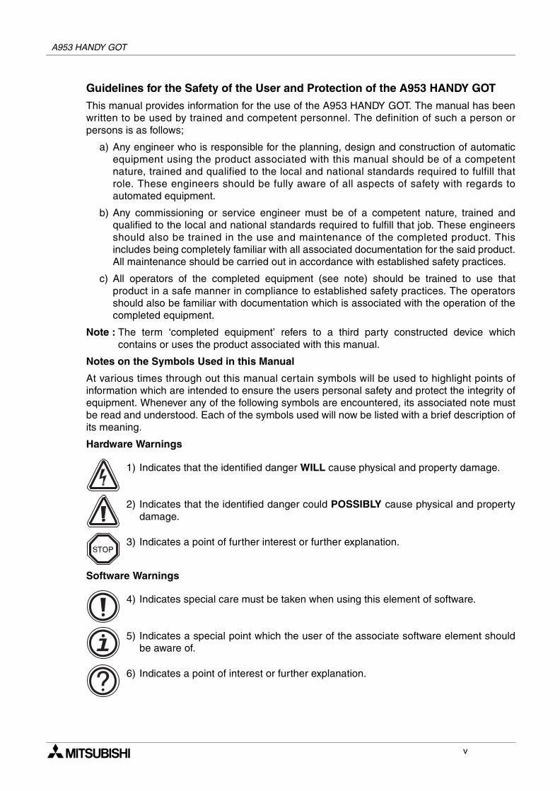
Notes on the Symbols Used in this Manual
At various times through out this manual certain symbols will be used to highlight points ofinformation which are intended to ensure the users personal safety and protect the integrity ofequipment. Whenever any of the following symbols are encountered, its associated note mustbe read and understood. Each of the symbols used will now be listed with a brief description ofits meaning.
Hardware Warnings
1) Indicates that the identified danger WILL cause physical and property damage.
2) Indicates that the identified danger could POSSIBLY cause physical and propertydamage.
3) Indicates a point of further interest or further explanation.
Software Warnings
4) Indicates special care must be taken when using this element of software.
5) Indicates a special point which the user of the associate software element shouldbe aware of.
6) Indicates a point of interest or further explanation.
v
A953 HANDY GOT
• Under no circumstances will Mitsubishi Electric be liable responsible for any consequentialdamage that may arise as a result of the installation or use of this equipment.
• All examples and diagrams shown in this manual are intended only as an aid tounderstanding the text, not to guarantee operation. Mitsubishi Electric will accept noresponsibility for actual use of the product based on these illustrative examples.
• Please contact a Mitsubishi Electric distributor for more information concerning applicationsin life critical situations or high reliability.
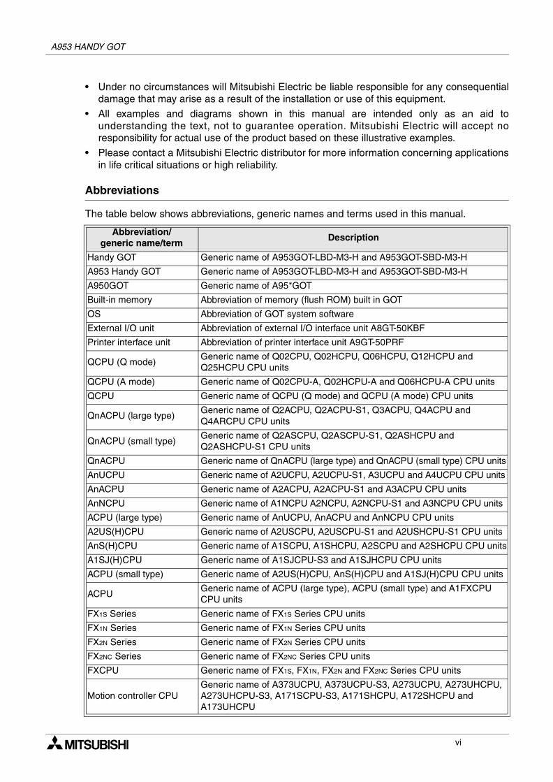
Abbreviations
The table below shows abbreviations, generic names and terms used in this manual.
Abbreviation/generic name/term
Description
Handy GOT Generic name of A953GOT-LBD-M3-H and A953GOT-SBD-M3-H
A953 Handy GOT Generic name of A953GOT-LBD-M3-H and A953GOT-SBD-M3-H
A950GOT Generic name of A95*GOT
Built-in memory Abbreviation of memory (flush ROM) built in GOT
OS Abbreviation of GOT system software
External I/O unit Abbreviation of external I/O interface unit A8GT-50KBF
Printer interface unit Abbreviation of printer interface unit A9GT-50PRF
QCPU (Q mode)Generic name of Q02CPU, Q02HCPU, Q06HCPU, Q12HCPU and Q25HCPU CPU units
QCPU (A mode) Generic name of Q02CPU-A, Q02HCPU-A and Q06HCPU-A CPU units
QCPU Generic name of QCPU (Q mode) and QCPU (A mode) CPU units
QnACPU (large type)Generic name of Q2ACPU, Q2ACPU-S1, Q3ACPU, Q4ACPU and Q4ARCPU CPU units
QnACPU (small type)Generic name of Q2ASCPU, Q2ASCPU-S1, Q2ASHCPU and Q2ASHCPU-S1 CPU units
QnACPU Generic name of QnACPU (large type) and QnACPU (small type) CPU units
AnUCPU Generic name of A2UCPU, A2UCPU-S1, A3UCPU and A4UCPU CPU units
AnACPU Generic name of A2ACPU, A2ACPU-S1 and A3ACPU CPU units
AnNCPU Generic name of A1NCPU A2NCPU, A2NCPU-S1 and A3NCPU CPU units
ACPU (large type) Generic name of AnUCPU, AnACPU and AnNCPU CPU units
A2US(H)CPU Generic name of A2USCPU, A2USCPU-S1 and A2USHCPU-S1 CPU units
AnS(H)CPU Generic name of A1SCPU, A1SHCPU, A2SCPU and A2SHCPU CPU units
A1SJ(H)CPU Generic name of A1SJCPU-S3 and A1SJHCPU CPU units
ACPU (small type) Generic name of A2US(H)CPU, AnS(H)CPU and A1SJ(H)CPU CPU units
ACPUGeneric name of ACPU (large type), ACPU (small type) and A1FXCPU CPU units
FX1S Series Generic name of FX1S Series CPU units
FX1N Series Generic name of FX1N Series CPU units
FX2N Series Generic name of FX2N Series CPU units
FX2NC Series Generic name of FX2NC Series CPU units
FXCPU Generic name of FX1S, FX1N, FX2N and FX2NC Series CPU units
Motion controller CPUGeneric name of A373UCPU, A373UCPU-S3, A273UCPU, A273UHCPU, A273UHCPU-S3, A171SCPU-S3, A171SHCPU, A172SHCPU and A173UHCPU
vi
A953 HANDY GOT
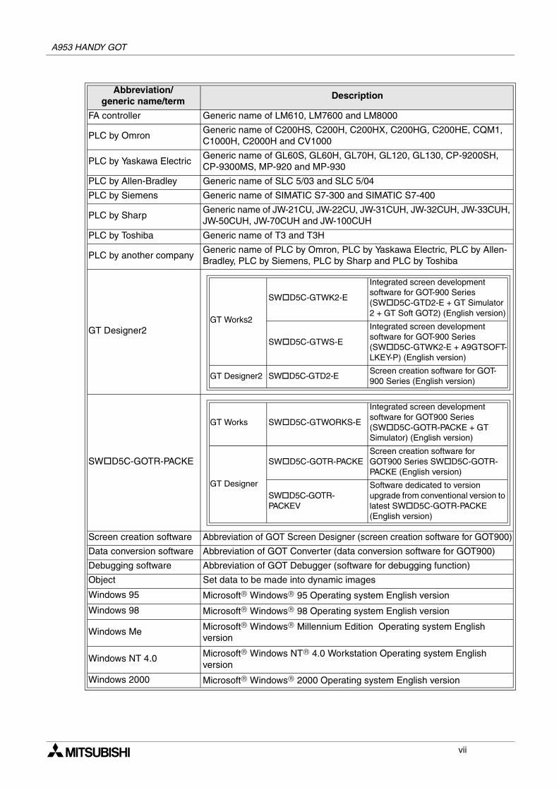
FA controller Generic name of LM610, LM7600 and LM8000
PLC by OmronGeneric name of C200HS, C200H, C200HX, C200HG, C200HE, CQM1, C1000H, C2000H and CV1000
PLC by Yaskawa ElectricGeneric name of GL60S, GL60H, GL70H, GL120, GL130, CP-9200SH, CP-9300MS, MP-920 and MP-930
PLC by Allen-Bradley Generic name of SLC 5/03 and SLC 5/04
PLC by Siemens Generic name of SIMATIC S7-300 and SIMATIC S7-400
PLC by SharpGeneric name of JW-21CU, JW-22CU, JW-31CUH, JW-32CUH, JW-33CUH, JW-50CUH, JW-70CUH and JW-100CUH
PLC by Toshiba Generic name of T3 and T3H
PLC by another companyGeneric name of PLC by Omron, PLC by Yaskawa Electric, PLC by Allen-Bradley, PLC by Siemens, PLC by Sharp and PLC by Toshiba
GT Designer2
SW D5C-GOTR-PACKE
Screen creation software Abbreviation of GOT Screen Designer (screen creation software for GOT900)
Data conversion software Abbreviation of GOT Converter (data conversion software for GOT900)
Debugging software Abbreviation of GOT Debugger (software for debugging function)
Object Set data to be made into dynamic images
Windows 95 Microsoft® Windows® 95 Operating system English version
Windows 98 Microsoft® Windows® 98 Operating system English version
Windows Me Microsoft® Windows® Millennium Edition Operating system English version
Windows NT 4.0 Microsoft® Windows NT® 4.0 Workstation Operating system English version
Windows 2000 Microsoft® Windows® 2000 Operating system English version
Abbreviation/generic name/term
Description
GT Works2
SW D5C-GTWK2-E
Integrated screen development software for GOT-900 Series (SW D5C-GTD2-E + GT Simulator 2 + GT Soft GOT2) (English version)
SW D5C-GTWS-E
Integrated screen development software for GOT-900 Series (SW D5C-GTWK2-E + A9GTSOFT-LKEY-P) (English version)
GT Designer2 SW D5C-GTD2-EScreen creation software for GOT-900 Series (English version)
GT Works SW D5C-GTWORKS-E
Integrated screen development software for GOT900 Series (SW D5C-GOTR-PACKE + GT Simulator) (English version)
GT Designer
SW D5C-GOTR-PACKEScreen creation software for GOT900 Series SW D5C-GOTR-PACKE (English version)
SW D5C-GOTR-PACKEV
Software dedicated to version upgrade from conventional version to latest SW D5C-GOTR-PACKE (English version)
vii
A953 HANDY GOT
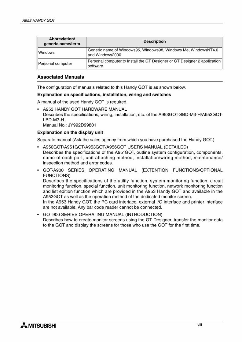
Associated Manuals
The configuration of manuals related to this Handy GOT is as shown below.
Explanation on specifications, installation, wiring and switches
A manual of the used Handy GOT is required.
• A953 HANDY GOT HARDWARE MANUALDescribes the specifications, wiring, installation, etc. of the A953GOT-SBD-M3-H/A953GOT-LBD-M3-H.Manual No.: JY992D99801
Explanation on the display unit
Separate manual (Ask the sales agency from which you have purchased the Handy GOT.)
• A950GOT/A951GOT/A953GOT/A956GOT USERS MANUAL (DETAILED)Describes the specifications of the A95*GOT, outline system configuration, components,name of each part, unit attaching method, installation/wiring method, maintenance/inspection method and error codes.
• GOT-A900 SERIES OPERATING MANUAL (EXTENTION FUNCTIONS/OPTIONALFUNCTIONS)Describes the specifications of the utility function, system monitoring function, circuitmonitoring function, special function, unit monitoring function, network monitoring functionand list edition function which are provided in the A953 Handy GOT and available in theA953GOT as well as the operation method of the dedicated monitor screen.In the A953 Handy GOT, the PC card interface, external I/O interface and printer interfaceare not available. Any bar code reader cannot be connected.
• GOT900 SERIES OPERATING MANUAL (INTRODUCTION)Describes how to create monitor screens using the GT Designer, transfer the monitor datato the GOT and display the screens for those who use the GOT for the first time.
WindowsGeneric name of Windows95, Windows98, Windows Me, WindowsNT4.0 and Windows2000
Personal computerPersonal computer to Install the GT Designer or GT Designer 2 application software
Abbreviation/generic name/term
Description
viii
A953 HANDY GOT
Screen creation software
• GT Works2/GT Designer2 OPERATING MANUAL (STARTUP)Describes how to install the GT Works2/GT Designer2 to a personal computer and how torefer to the online manual.
• GT Designer2 (SW D5C-GTD2-E) REFERENCE MANUAL -separate manual-Describes how to install and start up the screen creation software (GT Designer2).
• GT Designer2 (SW D5C-GTD2-E) OPERATING MANUAL -separate manual-Describes how to operate the screen creation software (GT Designer2).
• GT Works Version 5/GT Designer Version 5 OPERATING MANUAL (STARTUP)Describes how to install the GT Works Version 5/GT Designer Version 5 to a personalcomputer and how to refer to the online manual.(This manual is packed together with the GT Works Version 5/GT Designer Version 5.)
• GT Works Version 5/GT Designer Version 5 REFERENCE MANUAL -separate manual-Describes the system configuration of the GT Works Version 5/GT Designer Version 5, thescreen configuration of the GT Designer, various monitoring functions, procedures up todisplaying the monitor screen in the GOT and the help function use method.
• GT Simulator Version 5 OPERATING MANUAL -separate manual-Describes the system configuration, screen configuration and use method of the GTSimulator.
Registration
Microsoft® Windows®, Windows® 95, Windows® 98, Windows® Millennium Edition, WindowsNT® 4.0 Workstation and Windows® 2000 are either registered trademarks or trademarks ofMicrosoft Corporation in United States and/or other countries.The company name and the product name to be described in this manual are the registeredtrademarks or trademarks of each company.
ix
A953 HANDY GOT
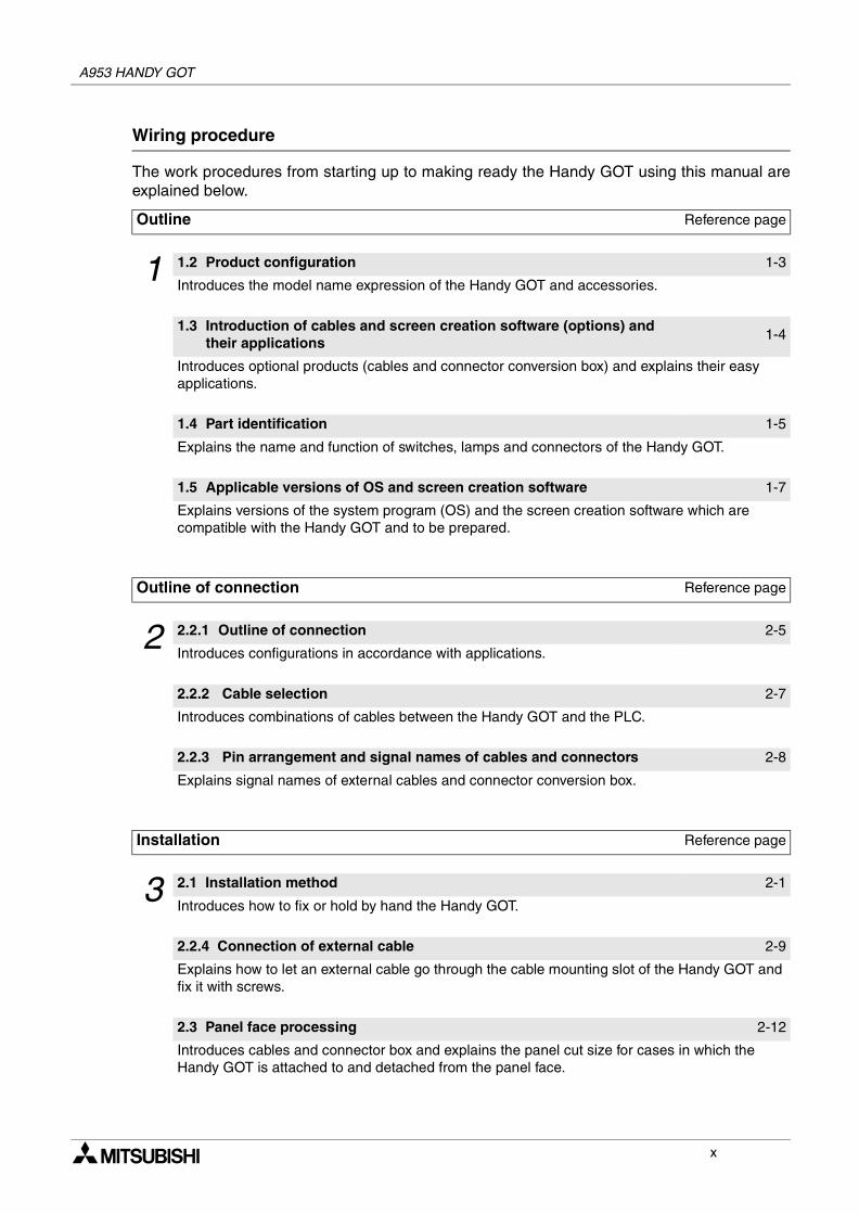
Wiring procedure
The work procedures from starting up to making ready the Handy GOT using this manual areexplained below.
Outline Reference page
1 1.2 Product configuration 1-3
Introduces the model name expression of the Handy GOT and accessories.
1.3 Introduction of cables and screen creation software (options) and their applications
1-4
Introduces optional products (cables and connector conversion box) and explains their easy applications.
1.4 Part identification 1-5
Explains the name and function of switches, lamps and connectors of the Handy GOT.
1.5 Applicable versions of OS and screen creation software 1-7
Explains versions of the system program (OS) and the screen creation software which are compatible with the Handy GOT and to be prepared.
Outline of connection Reference page
2 2.2.1 Outline of connection 2-5
Introduces configurations in accordance with applications.
2.2.2 Cable selection 2-7
Introduces combinations of cables between the Handy GOT and the PLC.
2.2.3 Pin arrangement and signal names of cables and connectors 2-8
Explains signal names of external cables and connector conversion box.
Installation Reference page
3 2.1 Installation method 2-1
Introduces how to fix or hold by hand the Handy GOT.
2.2.4 Connection of external cable 2-9
Explains how to let an external cable go through the cable mounting slot of the Handy GOT and fix it with screws.
2.3 Panel face processing 2-12
Introduces cables and connector box and explains the panel cut size for cases in which the Handy GOT is attached to and detached from the panel face.
x
A953 HANDY GOT
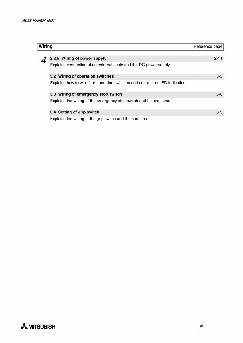
Wiring Reference page
4 2.2.5 Wiring of power supply 2-11
Explains connection of an external cable and the DC power supply.
3.2 Wiring of operation switches 3-5
Explains how to wire four operation switches and control the LED indication.
3.3 Wiring of emergency stop switch 3-8
Explains the wiring of the emergency stop switch and the cautions.
3.4 Setting of grip switch 3-9
Explains the wiring of the grip switch and the cautions.
xi

A953 HANDY GOT
MEMO
xii
Contents
Table of Contents
Guideline of Safty.................................................................................v
Abbreviations ...................................................................................................... viAssociated Manuals...........................................................................................viiiRegistration......................................................................................................... ixWiring procedure ................................................................................................. x
1. Introduction............................................................................................1-11.1 Outline of product ................................................................................................ 1-11.2 Product configuration........................................................................................... 1-3
1.2.1 Handy GOT ............................................................................................................... 1-31.3 Introduction of cables and screen creation software (options) and their
applications.......................................................................................................... 1-41.3.1 Common options ....................................................................................................... 1-41.3.2 Options dedicated to A953 Handy GOT.................................................................... 1-4
1.4 Part identification ................................................................................................. 1-51.4.1 Front panel ................................................................................................................ 1-51.4.2 Rear panel ................................................................................................................. 1-6
1.5 Applicable versions of OS and screen creation software .................................... 1-71.5.1 Applicable OS versions ............................................................................................. 1-71.5.2 Applicable screen creation software versions ........................................................... 1-7
2. Installation Wiring ..................................................................................2-12.1 Installation method .............................................................................................. 2-1
2.1.1 Holding ...................................................................................................................... 2-22.1.2 Hanging on wall ......................................................................................................... 2-32.1.3 Flat surface mounting ................................................................................................ 2-3
2.2 Wiring .................................................................................................................. 2-42.2.1 Outline of connection................................................................................................. 2-52.2.2 Cable selection.......................................................................................................... 2-62.2.3 Pin arrangement and signal names of cables and connectors.................................. 2-72.2.4 Connection of external cable..................................................................................... 2-82.2.5 Wiring of power supply ............................................................................................ 2-10
2.3 Panel face processing ....................................................................................... 2-112.3.1 A953 Handy GOT.................................................................................................... 2-112.3.2 Appearance of relay cables..................................................................................... 2-122.3.3 Panel cut size for relay cable .................................................................................. 2-13
A953 HANDY GOTA953 HANDY GOT
xiii
A953 HANDY GOT Contents
3. Wiring and Handling of Switches...........................................................3-13.1 Outline of switches .............................................................................................. 3-23.2 Wiring of operation switches................................................................................ 3-5
3.2.1 Inputs of operation switches...................................................................................... 3-53.2.2 Lighting of operation indicator LEDs ......................................................................... 3-6
3.3 Wiring of emergency stop switch......................................................................... 3-83.4 Setting of grip switch ........................................................................................... 3-9
3.4.1 Effectiveness/ineffectiveness of grip switch .............................................................. 3-93.4.2 Grip switch operation timing .................................................................................... 3-103.4.3 Communication with PLC ........................................................................................ 3-12
3.5 Creation of operation switch name sheet .......................................................... 3-143.5.1 Creation of name sheet ........................................................................................... 3-143.5.2 Attachment of sheet ................................................................................................ 3-15
4. Specifications ........................................................................................4-14.1 General specifications ......................................................................................... 4-2
4.1.1 Outside dimensions................................................................................................... 4-24.1.2 Power unit specifications........................................................................................... 4-34.1.3 General specifications ............................................................................................... 4-3
4.2 PLC CPU which can be monitored ...................................................................... 4-54.2.1 In case of A953 Handy GOT ..................................................................................... 4-5
4.3 Devices names which can be monitored ............................................................. 4-6
5. Connection to Peripheral Equipment.....................................................5-15.1 Connection to peripheral equipment for Handy GOT .......................................... 5-15.2 Cable connection procedure................................................................................ 5-15.3 Connection diagram ............................................................................................ 5-2
6. CPU Direct Connection .........................................................................6-16.1 System configuration ........................................................................................... 6-1
6.1.1 Connection to QCPU................................................................................................. 6-16.1.2 Connection to FXCPU ............................................................................................... 6-2
6.2 Connection cable................................................................................................. 6-3
7. Computer Link Connection....................................................................7-17.1 System configuration ........................................................................................... 7-17.2 Initial setting......................................................................................................... 7-2
7.2.1 Setting in communication link unit and serial communication unit............................. 7-27.2.2 Setting in GOT........................................................................................................... 7-6
7.3 Transmission specifications................................................................................. 7-67.4 Connection cable................................................................................................. 7-7
xiv
A953 HANDY GOT Contents
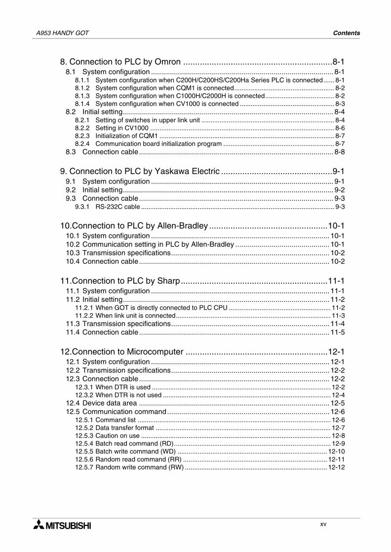
8. Connection to PLC by Omron ...............................................................8-18.1 System configuration ........................................................................................... 8-1
8.1.1 System configuration when C200H/C200HS/C200Ha Series PLC is connected...... 8-18.1.2 System configuration when CQM1 is connected....................................................... 8-28.1.3 System configuration when C1000H/C2000H is connected...................................... 8-28.1.4 System configuration when CV1000 is connected .................................................... 8-3
8.2 Initial setting......................................................................................................... 8-48.2.1 Setting of switches in upper link unit ......................................................................... 8-48.2.2 Setting in CV1000 ..................................................................................................... 8-68.2.3 Initialization of CQM1 ................................................................................................ 8-78.2.4 Communication board initialization program ............................................................. 8-7
8.3 Connection cable................................................................................................. 8-8
9. Connection to PLC by Yaskawa Electric ...............................................9-19.1 System configuration ........................................................................................... 9-19.2 Initial setting......................................................................................................... 9-29.3 Connection cable................................................................................................. 9-3
9.3.1 RS-232C cable .......................................................................................................... 9-3
10.Connection to PLC by Allen-Bradley ..................................................10-110.1 System configuration ......................................................................................... 10-110.2 Communication setting in PLC by Allen-Bradley ............................................... 10-110.3 Transmission specifications............................................................................... 10-210.4 Connection cable............................................................................................... 10-2
11.Connection to PLC by Sharp..............................................................11-111.1 System configuration ......................................................................................... 11-111.2 Initial setting....................................................................................................... 11-2
11.2.1 When GOT is directly connected to PLC CPU ........................................................ 11-211.2.2 When link unit is connected..................................................................................... 11-3
11.3 Transmission specifications............................................................................... 11-411.4 Connection cable............................................................................................... 11-5
12.Connection to Microcomputer ............................................................12-112.1 System configuration ......................................................................................... 12-112.2 Transmission specifications............................................................................... 12-212.3 Connection cable............................................................................................... 12-2
12.3.1 When DTR is used .................................................................................................. 12-212.3.2 When DTR is not used ............................................................................................ 12-4
12.4 Device data area ............................................................................................... 12-512.5 Communication command................................................................................. 12-6
12.5.1 Command list .......................................................................................................... 12-612.5.2 Data transfer format ................................................................................................ 12-712.5.3 Caution on use ........................................................................................................ 12-812.5.4 Batch read command (RD)...................................................................................... 12-912.5.5 Batch write command (WD) .................................................................................. 12-1012.5.6 Random read command (RR) ............................................................................... 12-1112.5.7 Random write command (RW) .............................................................................. 12-12
xv
A953 HANDY GOT Contents
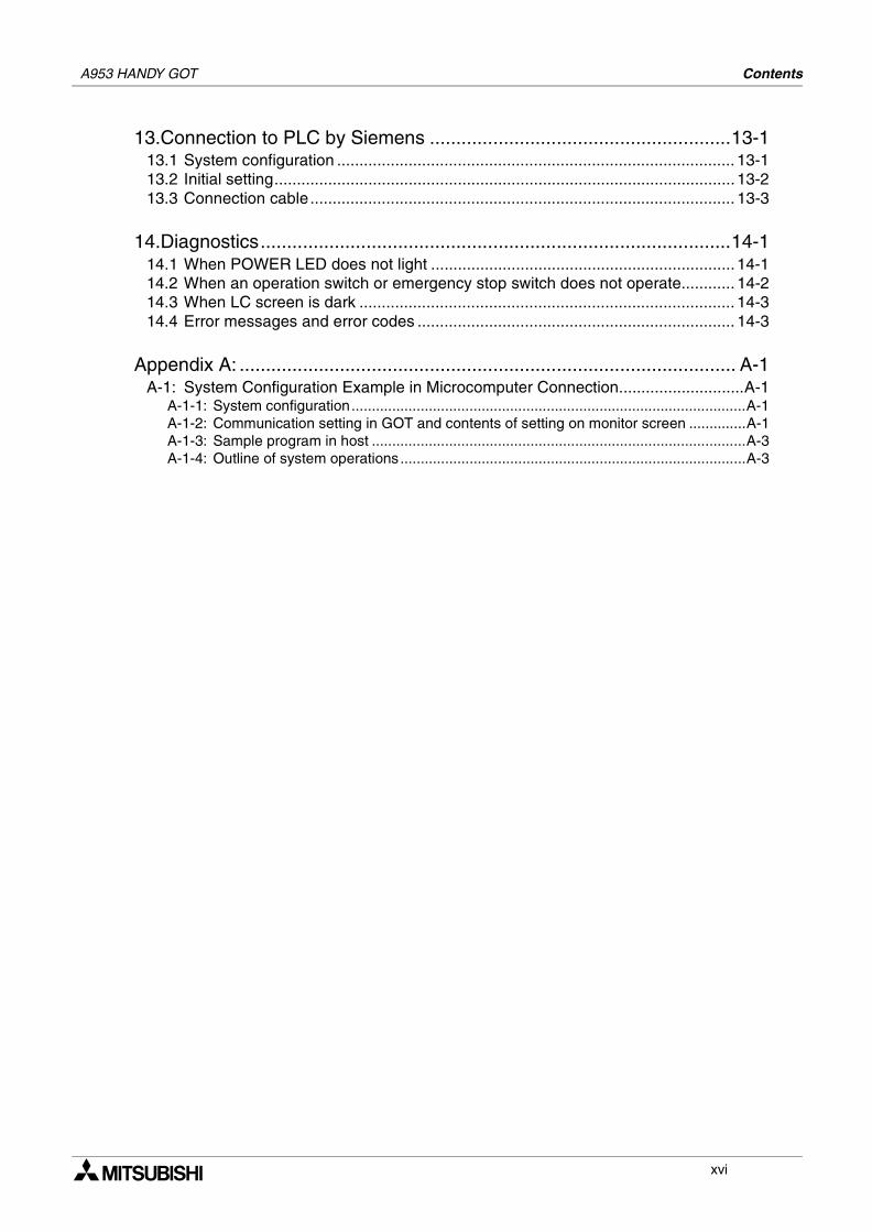
13.Connection to PLC by Siemens .........................................................13-113.1 System configuration ......................................................................................... 13-113.2 Initial setting....................................................................................................... 13-213.3 Connection cable............................................................................................... 13-3
14.Diagnostics.........................................................................................14-114.1 When POWER LED does not light .................................................................... 14-114.2 When an operation switch or emergency stop switch does not operate............ 14-214.3 When LC screen is dark .................................................................................... 14-314.4 Error messages and error codes ....................................................................... 14-3
Appendix A: .............................................................................................. A-1A-1: System Configuration Example in Microcomputer Connection............................A-1
A-1-1: System configuration.................................................................................................A-1A-1-2: Communication setting in GOT and contents of setting on monitor screen ..............A-1A-1-3: Sample program in host ............................................................................................A-3A-1-4: Outline of system operations.....................................................................................A-3
xvi
1
2
3
4
5
6
7
8
9
10
11
12
13
14
A
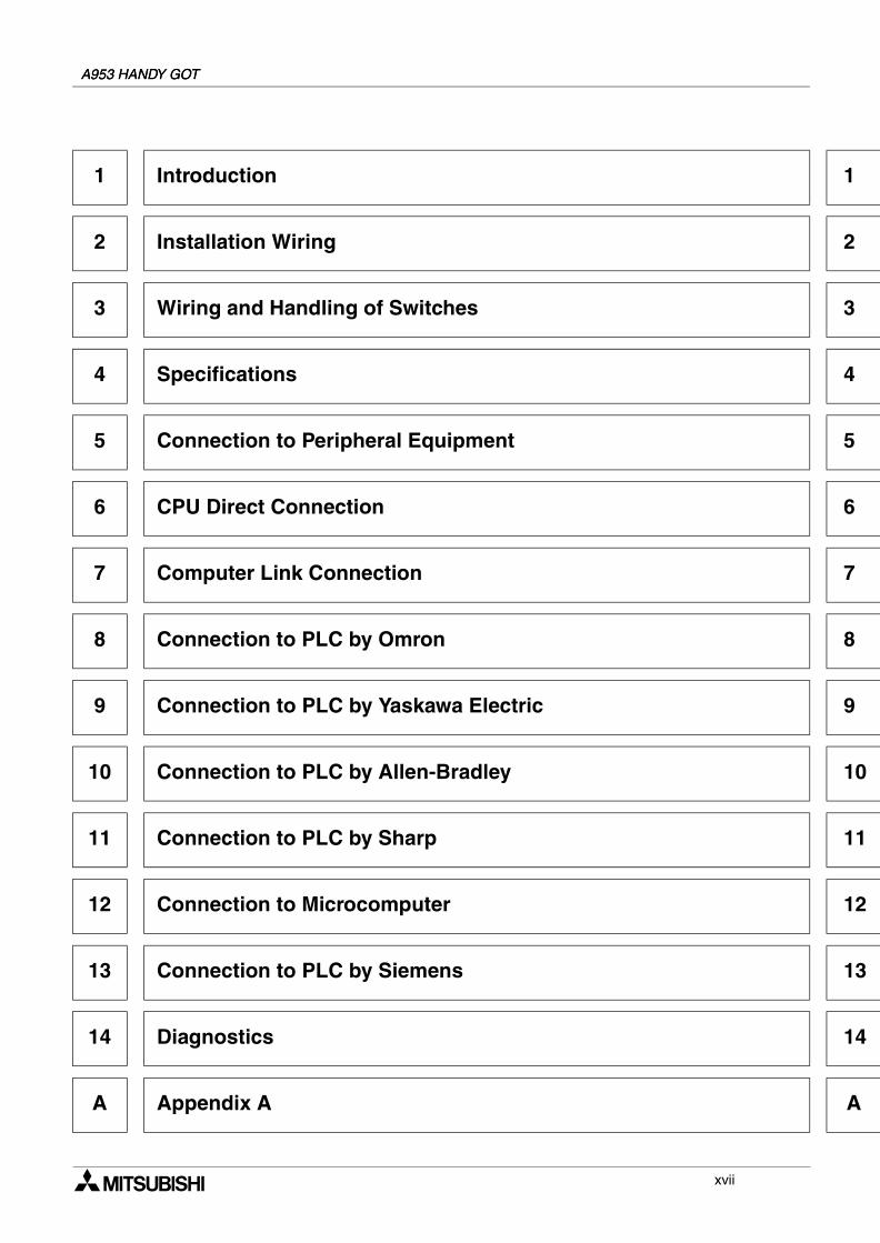
1 Introduction
2 Installation Wiring
3 Wiring and Handling of Switches
4 Specifications
5 Connection to Peripheral Equipment
6 CPU Direct Connection
7 Computer Link Connection
8 Connection to PLC by Omron
9 Connection to PLC by Yaskawa Electric
10 Connection to PLC by Allen-Bradley
11 Connection to PLC by Sharp
12 Connection to Microcomputer
13 Connection to PLC by Siemens
14 Diagnostics
A Appendix A
A953 HANDY GOTA953 HANDY GOT
xvii

A953 HANDY GOT
1 Introduction
2 Installation Wiring
3 Wiring and Handling of Switches
4 Specifications
5 Connection to Peripheral Equipment
6 CPU Direct Connection
7 Computer Link Connection
8 Connection to PLC by Omron
9 Connection to PLC by Yaskawa Electric
10 Connection to PLC by Allen-Bradley
11 Connection to PLC by Sharp
12 Connection to Microcomputer
13 Connection to PLC by Siemens
14 Diagnostics
A Appendix A
xviii
Introduction 1
1
2
3
4
5
6
7
8
9
10
11
12
13
14
A
1. Introduction
This section describes the product configuration and the system configuration of the A95handy graphic operation terminal (abbreviated as "Handy GOT" in the text).
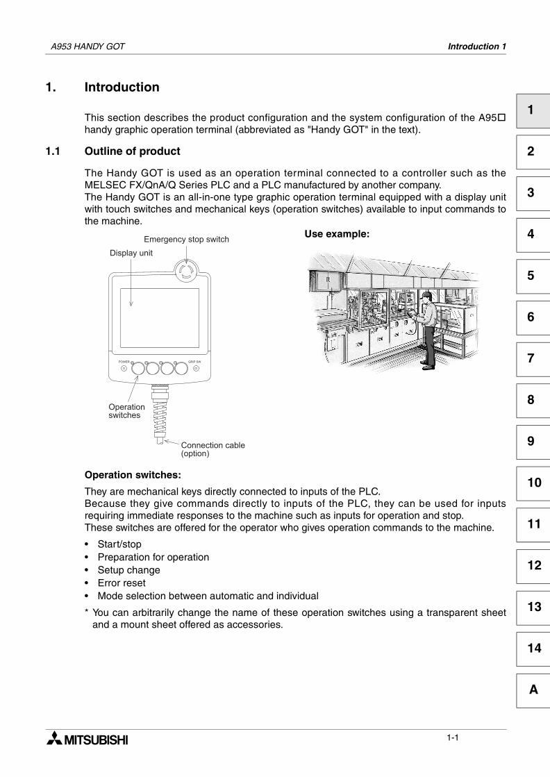
1.1 Outline of product
The Handy GOT is used as an operation terminal connected to a controller such as theMELSEC FX/QnA/Q Series PLC and a PLC manufactured by another company.The Handy GOT is an all-in-one type graphic operation terminal equipped with a display unitwith touch switches and mechanical keys (operation switches) available to input commands tothe machine.
Operation switches:
They are mechanical keys directly connected to inputs of the PLC.Because they give commands directly to inputs of the PLC, they can be used for inputsrequiring immediate responses to the machine such as inputs for operation and stop.These switches are offered for the operator who gives operation commands to the machine.
• Start/stop• Preparation for operation• Setup change• Error reset• Mode selection between automatic and individual
* You can arbitrarily change the name of these operation switches using a transparent sheetand a mount sheet offered as accessories.
Use example:
A953 HANDY GOT
1-1
A953 HANDY GOT Introduction 1
Display unit:
The display unit is an LCD with touch switches equivalent to that of the graphic operationterminal A950GOT.The operator can easily monitor the ON/OFF status of bit devices of the PLC, set such bitdevices to ON or OFF, monitor the set value and the present value of word devices of the PLC,and change such values of word devices.This display unit can be used to change the setup, change the set values, and performtroubleshooting by the engineer, as well as give guidance to the operator.
• Selection of individual operation• Independent operation• One-cycle operation• Monitoring• Forcedly turning ON/OFF• Change of set values• Troubleshooting
(You can create screens displayed on the display unit using the screen creation software whichruns in a personal computer.)
Connection cable:
An optional connection cable is offered to connect the PLC.
1-2
A953 HANDY GOT Introduction 1
1
2
3
4
5
6
7
8
9
10
11
12
13
14
A
1.2 Product configuration
The model name of the Handy GOT is expressed as follows.
A95 GOT- BD-M3-H1) 2)
1) 3: RS-232C communication type
2) S: STN type eight-color liquid crystalL: STN type black-and-white liquid crystal
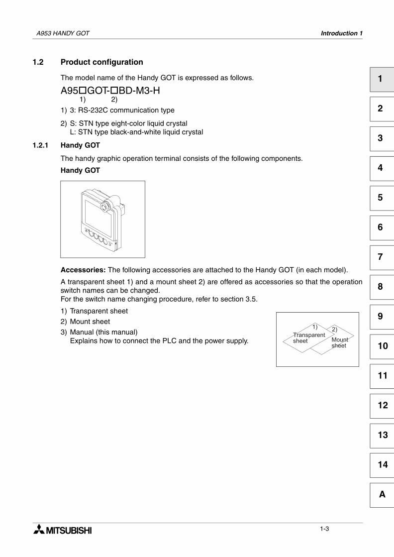
1.2.1 Handy GOT
The handy graphic operation terminal consists of the following components.
Handy GOT
Accessories: The following accessories are attached to the Handy GOT (in each model).
A transparent sheet 1) and a mount sheet 2) are offered as accessories so that the operationswitch names can be changed.For the switch name changing procedure, refer to section 3.5.
1) Transparent sheet
2) Mount sheet
3) Manual (this manual)Explains how to connect the PLC and the power supply.
!
"
#
1-3
A953 HANDY GOT Introduction 1
1.3 Introduction of cables and screen creation software (options) and their applications
Order the following options in accordance with the connected PLC configuration.
1.3.1 Common options
1) Screen creation software
For the details of versions applicable in the Handy GOT and thesoftware working environment, refer to 1.5.
- Screen creation system startup software SW D5C-GOTR-PACKE (V)"V" at the end of the model name indicates that this software isfor version upgrade.
- Screen creation system startup software SW D5C-GTD2-E
2) Protective sheets F9GT-40PSC (5 sheets in 1 set)
Each of these sheets protects the display unit against dirt whenadhered on the display unit.
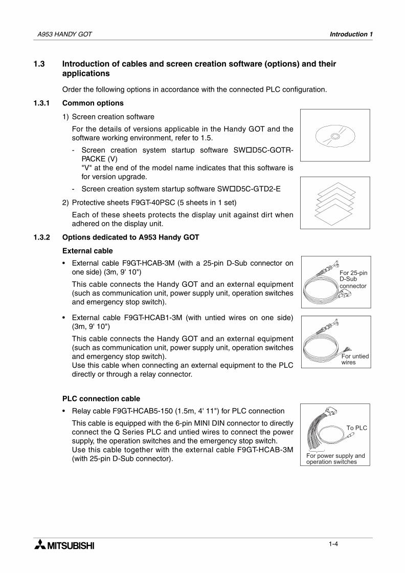
1.3.2 Options dedicated to A953 Handy GOT
External cable
• External cable F9GT-HCAB-3M (with a 25-pin D-Sub connector onone side) (3m, 9' 10")
This cable connects the Handy GOT and an external equipment(such as communication unit, power supply unit, operation switchesand emergency stop switch).
• External cable F9GT-HCAB1-3M (with untied wires on one side)(3m, 9' 10")
This cable connects the Handy GOT and an external equipment(such as communication unit, power supply unit, operation switchesand emergency stop switch).Use this cable when connecting an external equipment to the PLCdirectly or through a relay connector.
PLC connection cable
• Relay cable F9GT-HCAB5-150 (1.5m, 4' 11") for PLC connection
This cable is equipped with the 6-pin MINI DIN connector to directlyconnect the Q Series PLC and untied wires to connect the powersupply, the operation switches and the emergency stop switch.Use this cable together with the external cable F9GT-HCAB-3M(with 25-pin D-Sub connector).
$ %
$ ! & ' '
# (
$ %
1-4
A953 HANDY GOT Introduction 1
1
2
3
4
5
6
7
8
9
10
11
12
13
14
A
1.4 Part identification
This section roughly explains the name and function of each part of the Handy GOT.
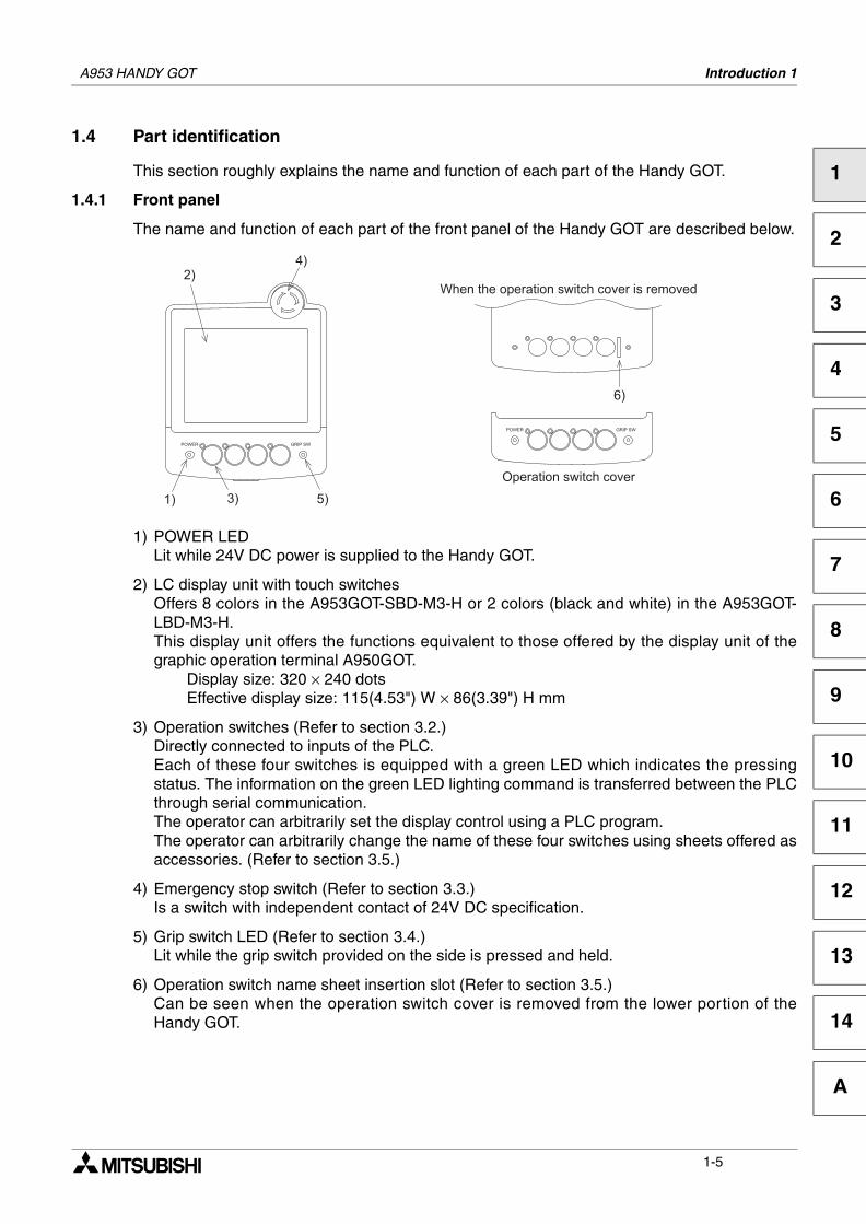
1.4.1 Front panel
The name and function of each part of the front panel of the Handy GOT are described below.
1) POWER LEDLit while 24V DC power is supplied to the Handy GOT.
2) LC display unit with touch switchesOffers 8 colors in the A953GOT-SBD-M3-H or 2 colors (black and white) in the A953GOT-LBD-M3-H.This display unit offers the functions equivalent to those offered by the display unit of thegraphic operation terminal A950GOT.
Display size: 320 × 240 dotsEffective display size: 115(4.53") W × 86(3.39") H mm
3) Operation switches (Refer to section 3.2.)Directly connected to inputs of the PLC.Each of these four switches is equipped with a green LED which indicates the pressingstatus. The information on the green LED lighting command is transferred between the PLCthrough serial communication.The operator can arbitrarily set the display control using a PLC program. The operator can arbitrarily change the name of these four switches using sheets offered asaccessories. (Refer to section 3.5.)
4) Emergency stop switch (Refer to section 3.3.)Is a switch with independent contact of 24V DC specification.
5) Grip switch LED (Refer to section 3.4.)Lit while the grip switch provided on the side is pressed and held.
6) Operation switch name sheet insertion slot (Refer to section 3.5.)Can be seen when the operation switch cover is removed from the lower portion of theHandy GOT.
!
)
*
&
+ + %
+
,
1-5
A953 HANDY GOT Introduction 1
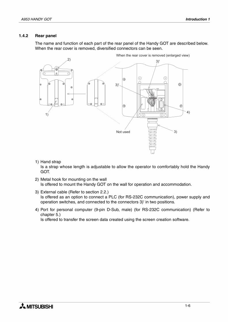
1.4.2 Rear panel
The name and function of each part of the rear panel of the Handy GOT are described below.When the rear cover is removed, diversified connectors can be seen.
1) Hand strapIs a strap whose length is adjustable to allow the operator to comfortably hold the HandyGOT.
2) Metal hook for mounting on the wallIs offered to mount the Handy GOT on the wall for operation and accommodation.
3) External cable (Refer to section 2.2.)Is offered as an option to connect a PLC (for RS-232C communication), power supply andoperation switches, and connected to the connectors 3)' in two positions.
4) Port for personal computer (9-pin D-Sub, male) (for RS-232C communication) (Refer tochapter 5.)Is offered to transfer the screen data created using the screen creation software.
!
) -
. % )
*
) -
+ + % % +
1-6
A953 HANDY GOT Introduction 1
1
2
3
4
5
6
7
8
9
10
11
12
13
14
A
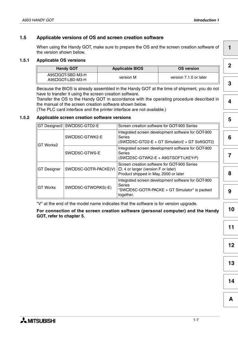
1.5 Applicable versions of OS and screen creation software
When using the Handy GOT, make sure to prepare the OS and the screen creation software ofthe version shown below.
1.5.1 Applicable OS versions
Because the BIOS is already assembled in the Handy GOT at the time of shipment, you do nothave to transfer it using the screen creation software.Transfer the OS to the Handy GOT in accordance with the operating procedure described inthe manual of the screen creation software shown below.(The PLC card interface and the printer interface are not available.)
1.5.2 Applicable screen creation software versions
"V" at the end of the model name indicates that the software is for version upgrade.
For connection of the screen creation software (personal computer) and the HandyGOT, refer to chapter 5.
Handy GOT Applicable BIOS OS version
A95 GOT-SBD-M3-HA95 GOT-LBD-M3-H
version M version 7.1.0 or later
GT Designer2 SW D5C-GTD2-E Screen creation software for GOT-900 Series
GT Works2
SW D5C-GTWK2-EIntegrated screen development software for GOT-900 Series(SW D5C-GTD2-E + GT Simulator2 + GT SoftGOT2)
SW D5C-GTWS-EIntegrated screen development software for GOT-900 Series(SW D5C-GTWK2-E + A9GTSOFT-LKEY-P)
GT Designer SW D5C-GOTR-PACKE(V)Screen creation software for GOT-900 Series
: 4 or larger (version F or later)Product shipped in May, 2000 or later
GT Works SW D5C-GTWORKS(-E)
Integrated screen development software for GOT-900 Series"SW D5C-GOTR-PACKE + GT Simulator" is packed together.
1-7

A953 HANDY GOT Introduction 1
MEMO
1-8
Installation Wiring 2
1
2
3
4
5
6
7
8
9
10
11
12
13
14
A
2. Installation Wiring
This section describes installation of the Handy GOT and wiring of the power supply and theoperation switches.Thoroughly understand the specifications before performing installation and wiring.
2.1 Installation method
Cautions on installation
• Use the Handy GOT in the general specifications environment described in this manual.Do not use the Handy GOT in a place with dusts, soot, conductive dusts, corrosive gas orflammable gas, place exposed to high temperature, dew condensation, direct sunlight,wind and rain, or place exposed to vibration or impact.If the Handy GOT is used in such a place, electrical shock, fire, malfunction, productdamage or deterioration may caused.
• Never drop cutting chips and electric wire chips into the ventilation window of the HandyGOT when you drill screw holes or perform wiring.Otherwise, fire, failure or malfunction may be caused.
• Connect connection cables securely to the specified connectors while the power isturned OFF.Imperfect connection may cause malfunction or failure.
• When connecting cables, pay attention to the contents described in this section.Especially, attach the rear cover so that PCBs inside the Handy GOT are not interferedwith connection cables.
Cautions on wiring
• Make sure to attach the rear cover to the Handy GOT before turning on the power andstarting operation after the installation or wiring work.Otherwise, electrical shock may be caused.
• Make sure to shut down all phases of the power outside the Handy GOT before startingthe installation or wiring work.Otherwise, electrical shock and damage of Handy GOT may be caused.
A953 HANDY GOT
2-1
A953 HANDY GOT Installation Wiring 2
Cautions on wiring
• The Handy GOT has the DC power specifications. Connect the DC power cable to thededicated terminals described in this manual.If the AC power is supplied to the power supply, operation switches or emergency stopswitches, the Handy GOT may be burnt.
• Correctly connect the 24V DC power cable (terminals) of the Handy GOT to [+][-] of theDC power supply unit as described in this manual.If reversing the terminals will seriously damage the Handy GOT.
• Perform the groundings to the drain wire (FG) of the Handy GOT. Never perform commongrounding with the strong power system.
• When processing a cable or executing the wiring work, pay attention so that cutting chipsand wire chips do not enter the inside of the Handy GOT.Such chips may cause fire, failure or malfunction.
Note
Even if the power is interrupted for less than 1 ms, the Handy GOT continues operation. If thepower is interrupted for a long time or the voltage is dropped, the Handy GOT stops operation.When the power is restored, however, the GOT automatically restarts operation.
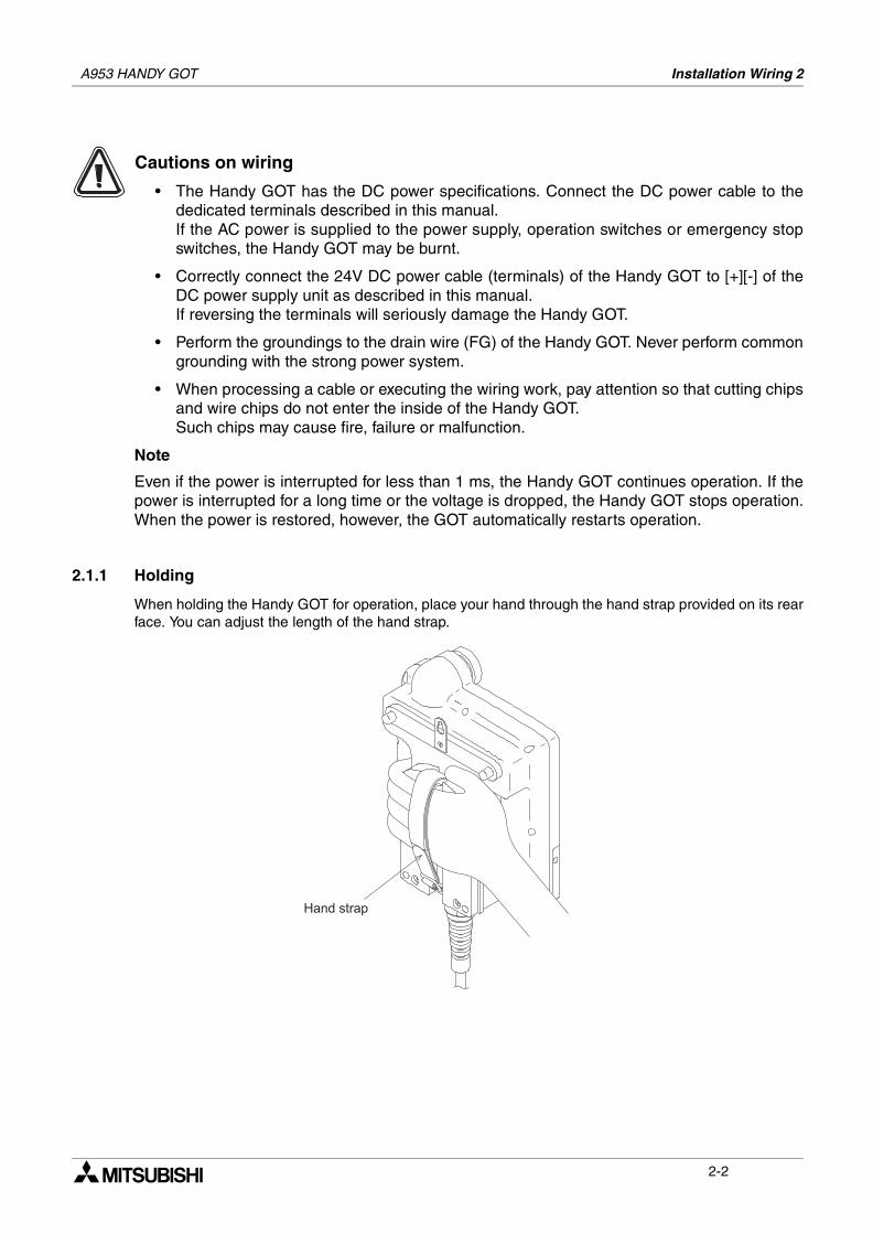
2.1.1 Holding
When holding the Handy GOT for operation, place your hand through the hand strap provided on its rearface. You can adjust the length of the hand strap.
/ %
2-2
A953 HANDY GOT Installation Wiring 2
1
2
3
4
5
6
7
8
9
10
11
12
13
14
A
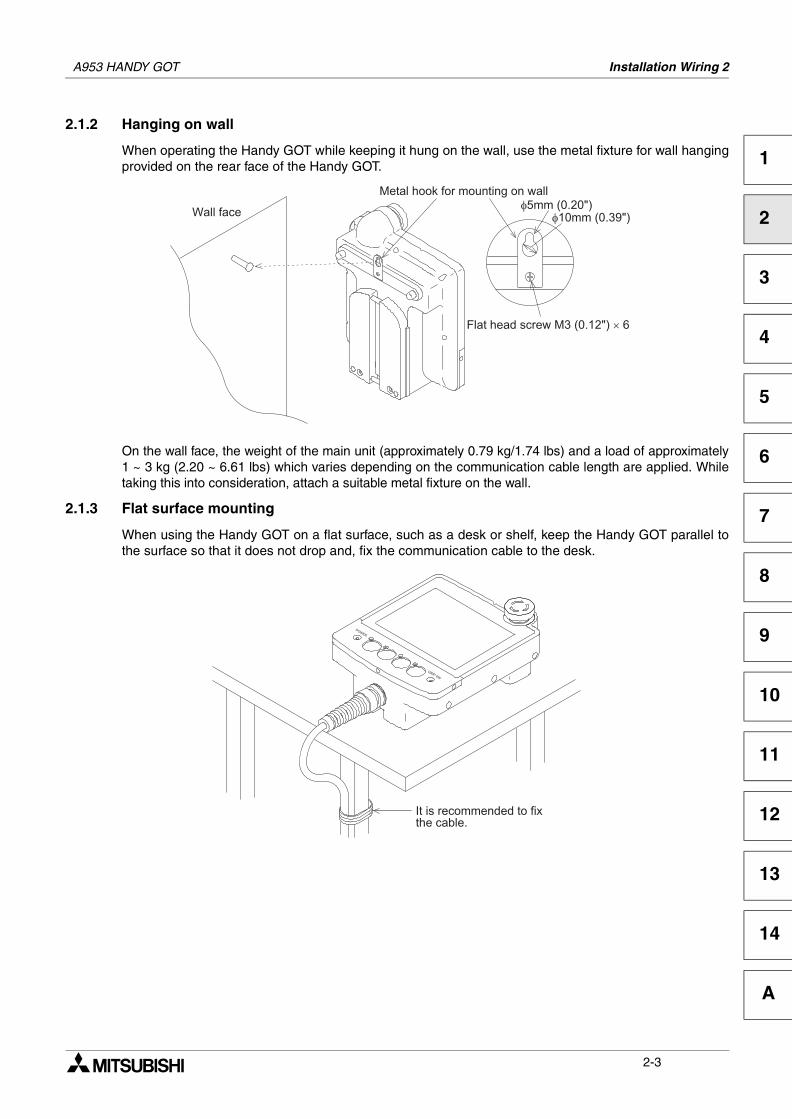
2.1.2 Hanging on wall
When operating the Handy GOT while keeping it hung on the wall, use the metal fixture for wall hangingprovided on the rear face of the Handy GOT.
On the wall face, the weight of the main unit (approximately 0.79 kg/1.74 lbs) and a load of approximately1 ~ 3 kg (2.20 ~ 6.61 lbs) which varies depending on the communication cable length are applied. Whiletaking this into consideration, attach a suitable metal fixture on the wall.
2.1.3 Flat surface mounting
When using the Handy GOT on a flat surface, such as a desk or shelf, keep the Handy GOT parallel tothe surface so that it does not drop and, fix the communication cable to the desk.
0
" 1 0 & 2 3 ! 2 4
2 2 3 ) 5 4
$ % " ) 2 3 ! 4 ,
% % 0 6 3
2-3
A953 HANDY GOT Installation Wiring 2
2.2 Wiring
Cautions on wiring
• Make sure to shut down all phases of the power supply outside the Handy GOT beforestarting the installation or wiring work.If any phase is not shut down, you may get electrical shock or the Handy GOT may bedamaged.
• Before turning on the power or starting operation after the installation or wiring work, makesure to attach the rear cover to the Handy GOT.If the rear cover is not attached, you may get electrical shock.
• The Handy GOT is designed for DC power. Correctly connect the DC power supply asdescribed in this manual.If the AC power supply is connected to the I/O terminals, the power terminals or theemergency stop switch, the Handy GOT may be burnt.
• Never drop cutting chips or electric wire chips into the inside of the Handy GOT whileprocessing connection cables or performing the wiring work. Such chips may cause fire,failure or malfunction.
• Perform Class D grounding to the drain wire (FG) of the Handy GOT. However, neverperform common grounding with a strong power system.
Note:
Even if instantaneous power interruption of less than 1ms occurs, the Handy GOT continues itsoperation.If long power interruption or voltage drop occurs, the Handy GOT stops its operation. Andwhen the power is recovered, the Handy GOT automatically restarts its operation.
2-4
A953 HANDY GOT Installation Wiring 2
1
2
3
4
5
6
7
8
9
10
11
12
13
14
A
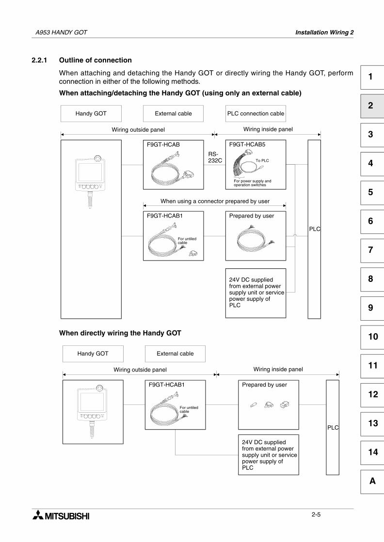
2.2.1 Outline of connection
When attaching and detaching the Handy GOT or directly wiring the Handy GOT, performconnection in either of the following methods.
When attaching/detaching the Handy GOT (using only an external cable)
When directly wiring the Handy GOT
F9GT-HCAB1 Prepared by user
When using a connector prepared by user
F9GT-HCAB F9GT-HCAB5
PLC
External cable PLC connection cable
Wiring inside panel
Handy GOT
Wiring outside panel
24V DC suppliedfrom external powersupply unit or servicepower supply ofPLC
RS-232C To PLC
For power supply andoperation switches
For untiledcable
F9GT-HCAB1
PLC
External cable
Wiring inside panel
Handy GOT
Wiring outside panel
Prepared by user
For untiledcable
24V DC suppliedfrom external powersupply unit or servicepower supply ofPLC
2-5
A953 HANDY GOT Installation Wiring 2
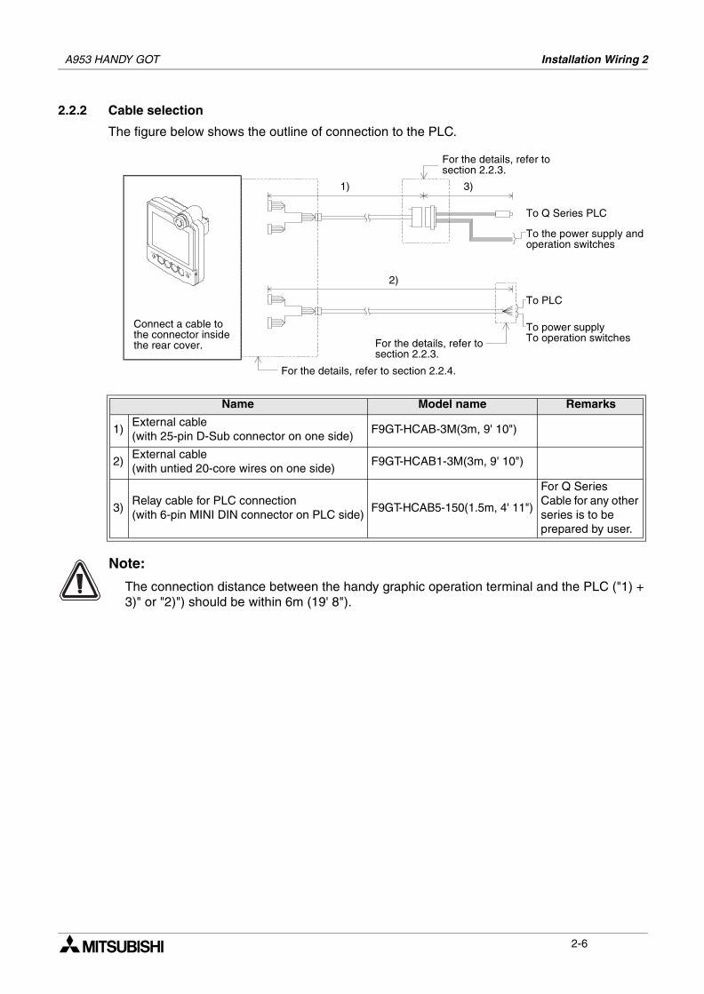
2.2.2 Cable selection
The figure below shows the outline of connection to the PLC.
Note:
The connection distance between the handy graphic operation terminal and the PLC ("1) + 3)" or "2)") should be within 6m (19' 8").
Name Model name Remarks
1)External cable(with 25-pin D-Sub connector on one side)
F9GT-HCAB-3M(3m, 9' 10")
2)External cable(with untied 20-core wires on one side)
F9GT-HCAB1-3M(3m, 9' 10")
3)Relay cable for PLC connection(with 6-pin MINI DIN connector on PLC side)
F9GT-HCAB5-150(1.5m, 4' 11")
For Q SeriesCable for any other series is to be prepared by user.
Connect a cable tothe connector insidethe rear cover.
1) 3)
To Q Series PLC
2)
For the details, refer to section 2.2.4.
For the details, refer tosection 2.2.3.
For the details, refer tosection 2.2.3.
To the power supply andoperation switches
To power supplyTo operation switches
To PLC
2-6
A953 HANDY GOT Installation Wiring 2
1
2
3
4
5
6
7
8
9
10
11
12
13
14
A
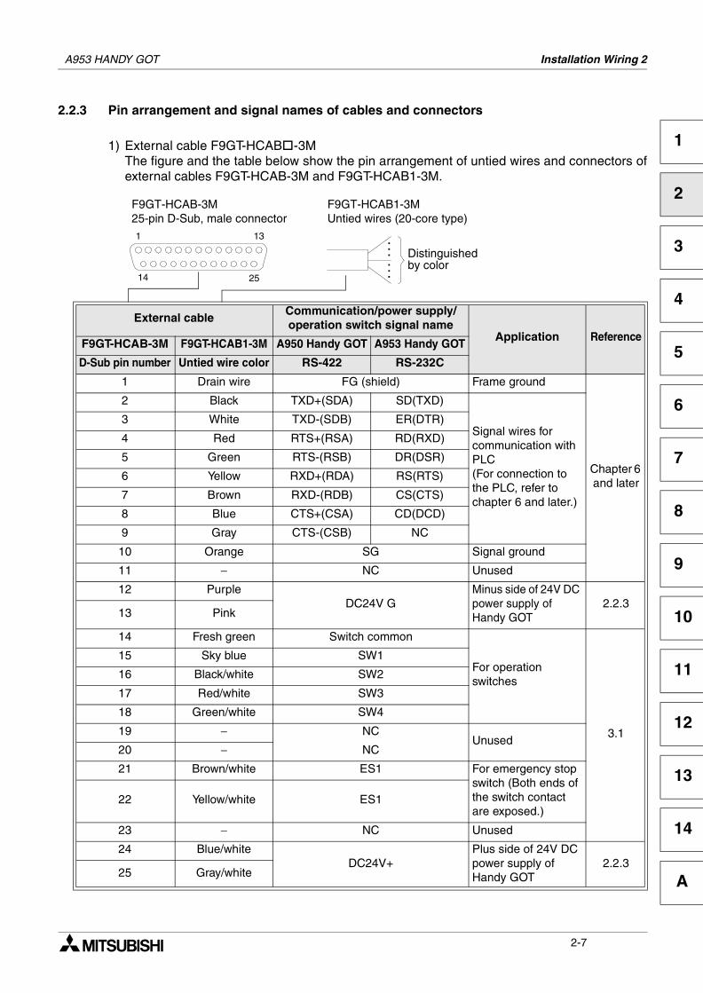
2.2.3 Pin arrangement and signal names of cables and connectors
1) External cable F9GT-HCAB -3MThe figure and the table below show the pin arrangement of untied wires and connectors ofexternal cables F9GT-HCAB-3M and F9GT-HCAB1-3M.
External cableCommunication/power supply/operation switch signal name
Application ReferenceF9GT-HCAB-3M F9GT-HCAB1-3M A950 Handy GOT A953 Handy GOT
D-Sub pin number Untied wire color RS-422 RS-232C
1 Drain wire FG (shield) Frame ground
Chapter 6 and later
2 Black TXD+(SDA) SD(TXD)
Signal wires for communication with PLC(For connection to the PLC, refer to chapter 6 and later.)
3 White TXD-(SDB) ER(DTR)
4 Red RTS+(RSA) RD(RXD)
5 Green RTS-(RSB) DR(DSR)
6 Yellow RXD+(RDA) RS(RTS)
7 Brown RXD-(RDB) CS(CTS)
8 Blue CTS+(CSA) CD(DCD)
9 Gray CTS-(CSB) NC
10 Orange SG Signal ground
11 − NC Unused
12 PurpleDC24V G
Minus side of 24V DC power supply of Handy GOT
2.2.313 Pink
14 Fresh green Switch common
For operation switches
3.1
15 Sky blue SW1
16 Black/white SW2
17 Red/white SW3
18 Green/white SW4
19 − NCUnused
20 − NC
21 Brown/white ES1 For emergency stop switch (Both ends of the switch contact are exposed.)
22 Yellow/white ES1
23 − NC Unused
24 Blue/whiteDC24V+
Plus side of 24V DC power supply of Handy GOT
2.2.325 Gray/white
1 13
14 25
F9GT-HCAB-3M25-pin D-Sub, male connector
. . .. . .
Distinguishedby color
F9GT-HCAB1-3MUntied wires (20-core type)
2-7
A953 HANDY GOT Installation Wiring 2
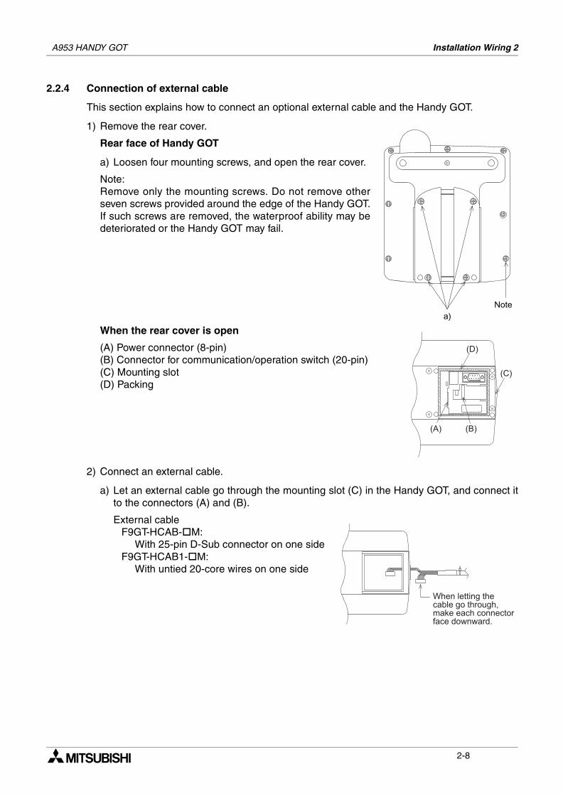
2.2.4 Connection of external cable
This section explains how to connect an optional external cable and the Handy GOT.
1) Remove the rear cover.
Rear face of Handy GOT
a) Loosen four mounting screws, and open the rear cover.
Note:Remove only the mounting screws. Do not remove otherseven screws provided around the edge of the Handy GOT.If such screws are removed, the waterproof ability may bedeteriorated or the Handy GOT may fail.
When the rear cover is open
(A) Power connector (8-pin)(B) Connector for communication/operation switch (20-pin)(C) Mounting slot(D) Packing
2) Connect an external cable.
a) Let an external cable go through the mounting slot (C) in the Handy GOT, and connect itto the connectors (A) and (B).
External cableF9GT-HCAB- M:
With 25-pin D-Sub connector on one sideF9GT-HCAB1- M:
With untied 20-core wires on one side
2-8
A953 HANDY GOT Installation Wiring 2
1
2
3
4
5
6
7
8
9
10
11
12
13
14
A
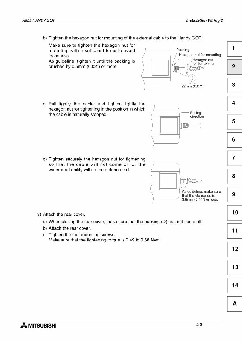
b) Tighten the hexagon nut for mounting of the external cable to the Handy GOT.
Make sure to tighten the hexagon nut formounting with a sufficient force to avoidlooseness.As guideline, tighten it until the packing iscrushed by 0.5mm (0.02") or more.
c) Pull lightly the cable, and tighten lightly thehexagon nut for tightening in the position in whichthe cable is naturally stopped.
d) Tighten securely the hexagon nut for tighteningso that the cable wi l l not come off or thewaterproof ability will not be deteriorated.
3) Attach the rear cover.
a) When closing the rear cover, make sure that the packing (D) has not come off.
b) Attach the rear cover.
c) Tighten the four mounting screws.Make sure that the tightening torque is 0.49 to 0.68 N•m.
! "
# $
# $
% % %& ' ( ) " % %
2-9
A953 HANDY GOT Installation Wiring 2
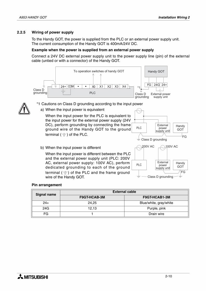
2.2.5 Wiring of power supply
To the Handy GOT, the power is supplied from the PLC or an external power supply unit.The current consumption of the Handy GOT is 400mA/24V DC.
Example when the power is supplied from an external power supply
Connect a 24V DC external power supply unit to the power supply line (pin) of the externalcable (untied or with a connector) of the Handy GOT.
Pin arrangement
Signal nameExternal cable
F9GT-HCAB-3M F9GT-HCAB1-3M
24+ 24,25 Blue/white, gray/white
24G 12,13 Purple, pink
FG 1 Drain wire
* $ +
% + + , -
% %
# ,. / 0
1 .
-
( 2 2
* $ +
% + + ,
% %
# ,. / 0
1 .
a) When the input power is equivalent
When the input power for the PLC is equivalent tothe input power for the external power supply (24VDC), perform grounding by connecting the frameground wire of the Handy GOT to the groundterminal ( ) of the PLC.
b) When the input power is different
When the input power is different between the PLCand the external power supply unit (PLC: 200VAC, external power supply: 100V AC), performdedicated grounding to each of the groundterminal ( ) of the PLC and the frame groundwire of the Handy GOT.
*1 Cautions on Class D grounding according to the input power
-
0 + % % , . / 0 # , . / 0
% %
% % * $ +
% + + ,
1 . ) 3 / 4 5 )5 5 ( 5 5 &
) 3 ) .6 (
2-10
A953 HANDY GOT Installation Wiring 2
1
2
3
4
5
6
7
8
9
10
11
12
13
14
A
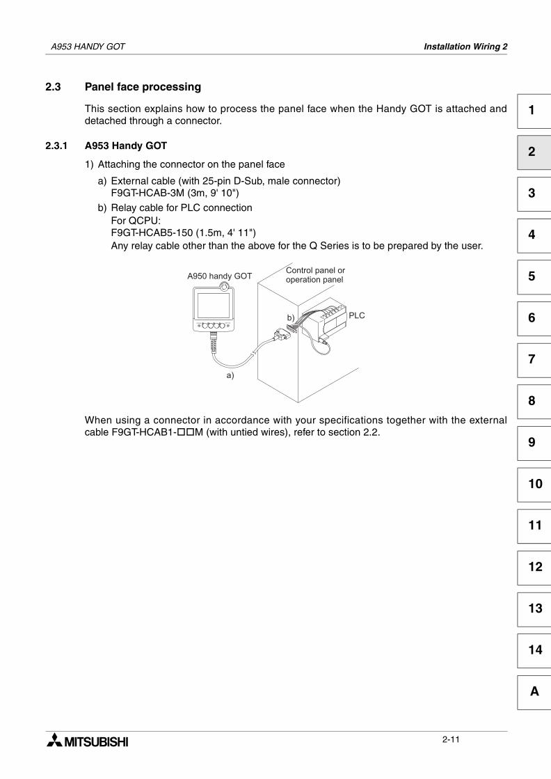
2.3 Panel face processing
This section explains how to process the panel face when the Handy GOT is attached anddetached through a connector.
2.3.1 A953 Handy GOT
1) Attaching the connector on the panel face
a) External cable (with 25-pin D-Sub, male connector)F9GT-HCAB-3M (3m, 9' 10")
b) Relay cable for PLC connectionFor QCPU:F9GT-HCAB5-150 (1.5m, 4' 11")Any relay cable other than the above for the Q Series is to be prepared by the user.
When using a connector in accordance with your specifications together with the externalcable F9GT-HCAB1- M (with untied wires), refer to section 2.2.
-
7 ' , . / 0 + + +
/ * 8 . 8 9 :
2-11
A953 HANDY GOT Installation Wiring 2
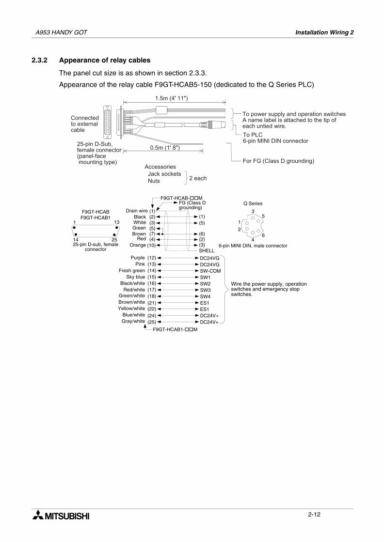
2.3.2 Appearance of relay cables
The panel cut size is as shown in section 2.3.3.
Appearance of the relay cable F9GT-HCAB5-150 (dedicated to the Q Series PLC)
0 + % + + , + % % % +
0 - ; < + 4 9 = 9 9 =
$
' < + < : + < , +
% % %
> % %
= %
( ' ) ? ( ( "
' ( ? "
1 1 . % %
F9GT-HCABF9GT-HCAB1
25-pin D-sub, femaleconnector
1 13
14 25
SHELL
(1)(2)(3)
(7)(4)
(5)
(10)
Drain wire
F9GT-HCAB- MFG (Class Dgrounding)
BlackWhiteGreenBrown
RedOrange
(1)(5)
(6)(2)(3)
(12) DC24VG(13) DC24VG(14) SW-COM(15) SW1(16) SW2(17) SW3(18) SW4
ES1ES1DC24V+DC24V+
F9GT-HCAB1- M
Wire the power supply, operationswitches and emergency stopswitches.
(21)(22)(24)(25)
PurplePink
Fresh greenSky blue
Black/whiteRed/white
Green/whiteBrown/whiteYellow/white
Blue/whiteGray/white
6-pin MINI DIN, male connector
Q Series
4
1
2
35
6
2-12
A953 HANDY GOT Installation Wiring 2
1
2
3
4
5
6
7
8
9
10
11
12
13
14
A
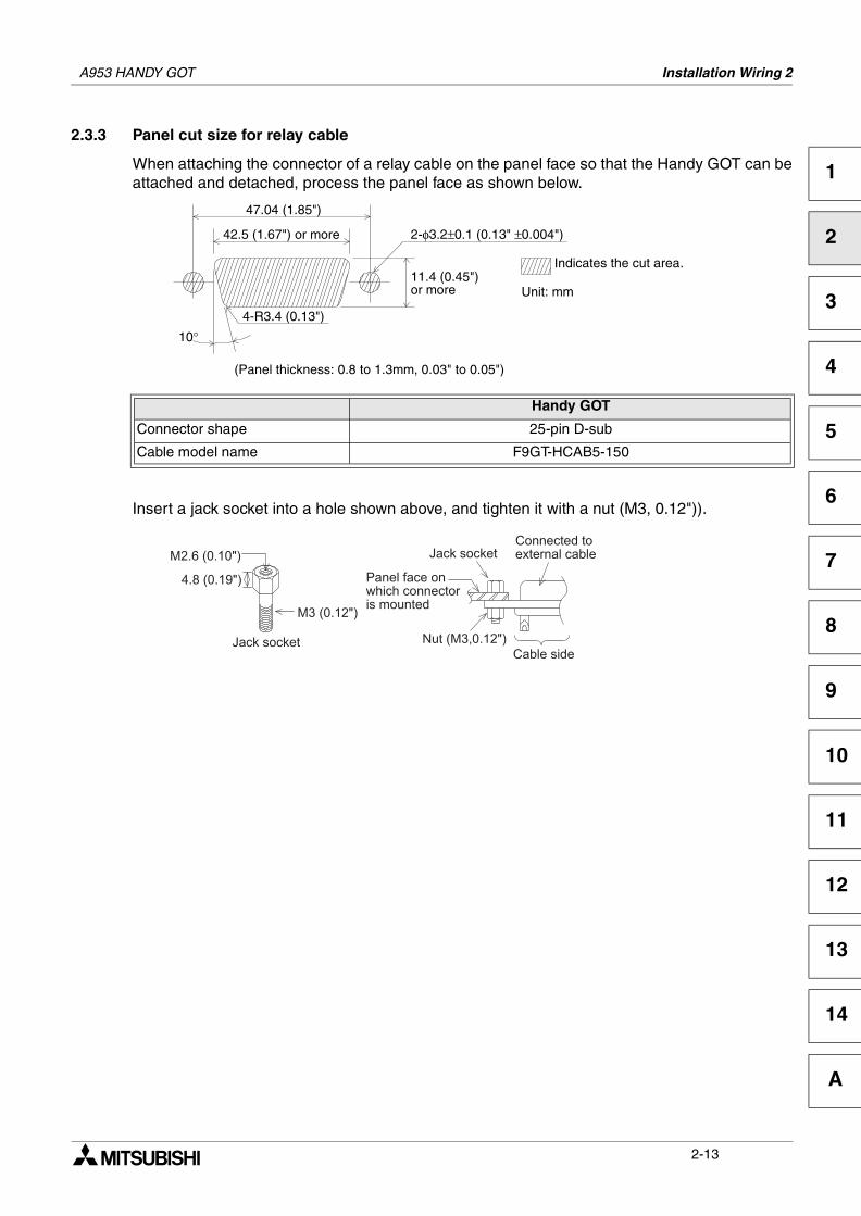
2.3.3 Panel cut size for relay cable
When attaching the connector of a relay cable on the panel face so that the Handy GOT can beattached and detached, process the panel face as shown below.
Insert a jack socket into a hole shown above, and tighten it with a nut (M3, 0.12")).
Handy GOT
Connector shape 25-pin D-sub
Cable model name F9GT-HCAB5-150
10°
42.5 (1.67") or more
47.04 (1.85")
2-φ3.2±0.1 (0.13" ±0.004")
11.4 (0.45")or more
Indicates the cut area.
Unit: mm
4-R3.4 (0.13")
(Panel thickness: 0.8 to 1.3mm, 0.03" to 0.05")
> % $
%
= 4 & ( "
%
4 ; ( "
4 & ( "
> %
) ( 7 "
2-13

A953 HANDY GOT Installation Wiring 2
MEMO
2-14
Wiring and Handling of Switches 3
1
2
3
4
5
6
7
8
9
10
11
12
13
14
A
3. Wiring and Handling of Switches
This chapter explains wiring and handling of the operation switches and the grip switch as wellas control of the LEDs for confirming the switch pressing status.
Cautions on installation
• Use the Handy GOT in the general specifications environment described in this manual.Do not use the Handy GOT in a place with dusts, soot, conductive dusts, corrosive gas orflammable gas, place exposed to high temperature, dew condensation, direct sunlight,wind and rain, or place exposed to vibration or impact.If the Handy GOT is used in such a place, electrical shock, fire, malfunction, productdamage or deterioration may caused.
• Never drop cutting chips and electric wire chips into the ventilation window of the HandyGOT when you drill screw holes or perform wiring.Otherwise, fire, failure or malfunction may be caused.
• Connect connection cables securely to the specified connectors while the power isturned OFF.Imperfect connection may cause malfunction or failure.
• When connecting cables, pay attention to the contents described in Chapter 2.Especially, attach the rear cover so that PCBs inside the Handy GOT are not interferedwith connection cables.
Cautions on wiring
• Make sure to attach the rear cover to the Handy GOT before turning on the power andstarting operation after the installation or wiring work.Otherwise, electrical shock may be caused.
• Make sure to shut down all phases of the power outside the Handy GOT before startingthe installation or wiring work.Otherwise, electrical shock and damage of Handy GOT may be caused.
Cautions on wiring
• The Handy GOT has the DC power specifications. Connect the DC power cable to thededicated terminals described in this manual.If the AC power is supplied to the power supply, operation switches or emergency stopswitches, the Handy GOT may be burnt.
• Correctly connect the 24V DC power cable (terminals) of the Handy GOT to [+][-] of theDC power supply unit as described in this manual.If reversing the terminals will seriously damage the Handy GOT.
• Perform the groundings to the drain wire (FG) of the Handy GOT. Never perform commongrounding with the strong power system.
• When processing a cable or executing the wiring work, pay attention so that cutting chipsand wire chips do not enter the inside of the Handy GOT.Such chips may cause fire, failure or malfunction.
A953 HANDY GOT
3-1
A953 HANDY GOT Wiring and Handling of Switches 3
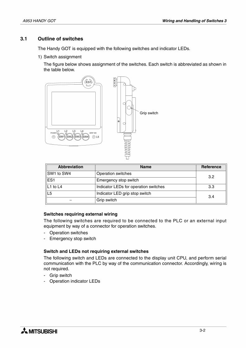
3.1 Outline of switches
The Handy GOT is equipped with the following switches and indicator LEDs.
1) Switch assignment
The figure below shows assignment of the switches. Each switch is abbreviated as shown inthe table below.
Switches requiring external wiringThe following switches are required to be connected to the PLC or an external inputequipment by way of a connector for operation switches.
- Operation switches- Emergency stop switch
Switch and LEDs not requiring external switchesThe following switch and LEDs are connected to the display unit CPU, and perform serialcommunication with the PLC by way of the communication connector. Accordingly, wiring isnot required.
- Grip switch- Operation indicator LEDs
Abbreviation Name Reference
SW1 to SW4 Operation switches3.2
ES1 Emergency stop switch
L1 to L4 Indicator LEDs for operation switches 3.3
L5 Indicator LED grip stop switch3.4
− Grip switch
3-2
A953 HANDY GOT Wiring and Handling of Switches 3
1
2
3
4
5
6
7
8
9
10
11
12
13
14
A
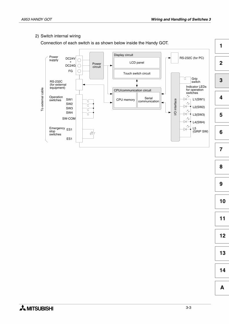
2) Switch internal wiring
Connection of each switch is as shown below inside the Handy GOT.
CPU memory
LCD panel
Touch switch circuit
Display circuit
Serialcommunication
CPU/communication circuit
RS-232C (for PC)DC24V+
DC24G
FG
RS-232C(for externalequipment)
Operationswitches SW1
SW2SW3SW4
Emergencystopswitches
ES1
ES1
To
exte
rnal
cab
le
SW-COM
Powercircuit
Powersupply
L1(SW1)
L2(SW2)
L3(SW3)
L4(SW4)
L5(GRIP SW)
Gripswitch
Indicator LEDsfor operationswitches
I/O in
terf
ace
3-3
A953 HANDY GOT Wiring and Handling of Switches 3
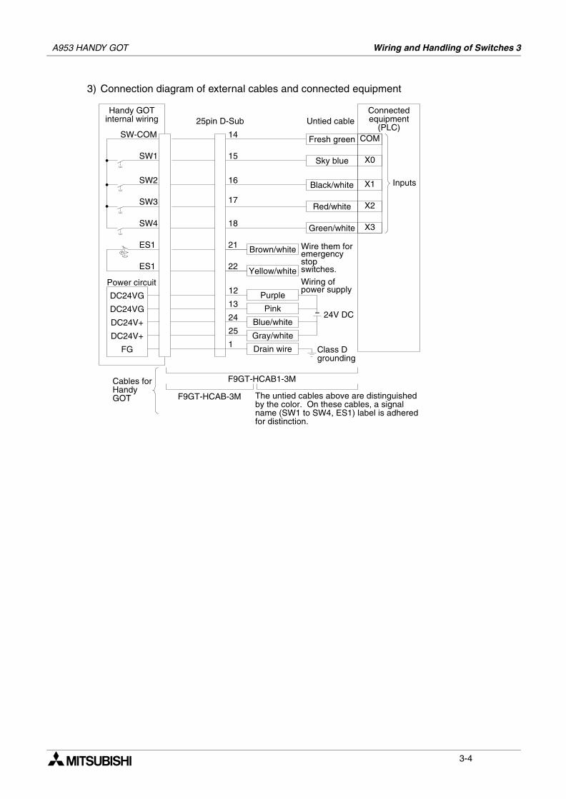
3) Connection diagram of external cables and connected equipment
SW-COM
SW1
SW2
Handy GOTinternal wiring
SW3
SW4
Connectedequipment
(PLC)
Inputs
ES1
ES1
Wire them foremergencystopswitches.
Fresh green
Sky blue
Black/white
Red/white
Green/white
Brown/white
Yellow/white
F9GT-HCAB-3M
F9GT-HCAB1-3MCables forHandyGOT
25pin D-Sub Untied cable
The untied cables above are distinguishedby the color. On these cables, a signalname (SW1 to SW4, ES1) label is adheredfor distinction.
14
15
16
Power circuit
18
21
22
17
DC24VG
DC24VG
DC24V+
DC24V+
12
13
24
25
24V DC
Purple
Pink
Blue/white
Gray/white
Wiring ofpower supply
FG Drain wire Class Dgrounding
1
COM
X0
X1
X2
X3
3-4
A953 HANDY GOT Wiring and Handling of Switches 3
1
2
3
4
5
6
7
8
9
10
11
12
13
14
A
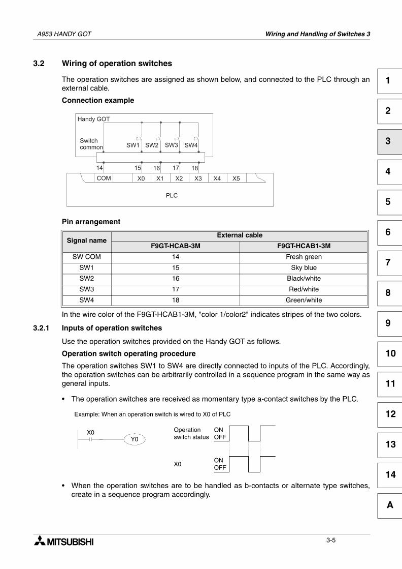
3.2 Wiring of operation switches
The operation switches are assigned as shown below, and connected to the PLC through anexternal cable.
Connection example
Pin arrangement
In the wire color of the F9GT-HCAB1-3M, "color 1/color2" indicates stripes of the two colors.
3.2.1 Inputs of operation switches
Use the operation switches provided on the Handy GOT as follows.
Operation switch operating procedure
The operation switches SW1 to SW4 are directly connected to inputs of the PLC. Accordingly,the operation switches can be arbitrarily controlled in a sequence program in the same way asgeneral inputs.
• The operation switches are received as momentary type a-contact switches by the PLC.
• When the operation switches are to be handled as b-contacts or alternate type switches,create in a sequence program accordingly.
Signal nameExternal cable
F9GT-HCAB-3M F9GT-HCAB1-3M
SW COM 14 Fresh green
SW1 15 Sky blue
SW2 16 Black/white
SW3 17 Red/white
SW4 18 Green/white
X0Y0
Example: When an operation switch is wired to X0 of PLC
ONOFF
ONOFF
Operationswitch status
X0
3-5
A953 HANDY GOT Wiring and Handling of Switches 3
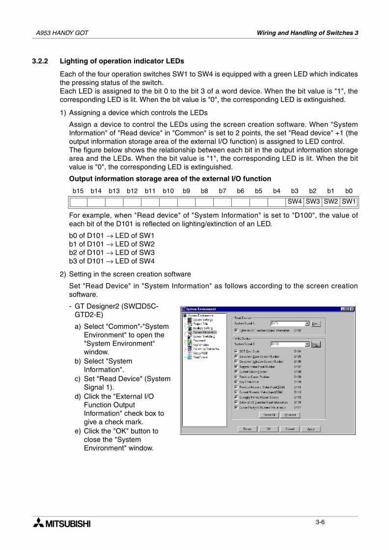
3.2.2 Lighting of operation indicator LEDs
Each of the four operation switches SW1 to SW4 is equipped with a green LED which indicatesthe pressing status of the switch.Each LED is assigned to the bit 0 to the bit 3 of a word device. When the bit value is "1", thecorresponding LED is lit. When the bit value is "0", the corresponding LED is extinguished.
1) Assigning a device which controls the LEDs
Assign a device to control the LEDs using the screen creation software. When "SystemInformation" of "Read device" in "Common" is set to 2 points, the set "Read device" +1 (theoutput information storage area of the external I/O function) is assigned to LED control.The figure below shows the relationship between each bit in the output information storagearea and the LEDs. When the bit value is "1", the corresponding LED is lit. When the bitvalue is "0", the corresponding LED is extinguished.
Output information storage area of the external I/O function
For example, when "Read device" of "System Information" is set to "D100", the value ofeach bit of the D101 is reflected on lighting/extinction of an LED.
b0 of D101 → LED of SW1b1 of D101 → LED of SW2b2 of D101 → LED of SW3b3 of D101 → LED of SW4
2) Setting in the screen creation software
Set "Read Device" in "System Information" as follows according to the screen creationsoftware.
- GT Designer2 (SW D5C-GTD2-E)
a) Select "Common"-"System Environment" to open the "System Environment" window.
b) Select "System Information".
c) Set "Read Device" (System Signal 1).
d) Click the "External I/O Function Output Information" check box to give a check mark.
e) Click the "OK" button to close the "System Environment" window.
b15 b14 b13 b12 b11 b10 b9 b8 b7 b6 b5 b4 b3 b2 b1 b0
SW4 SW3 SW2 SW1
3-6
A953 HANDY GOT Wiring and Handling of Switches 3
1
2
3
4
5
6
7
8
9
10
11
12
13
14
A
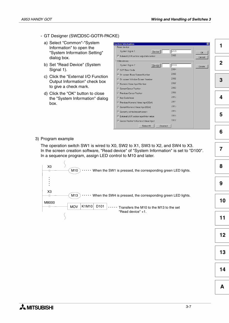
- GT Designer (SW D5C-GOTR-PACKE)
a) Select "Common"-"System Information" to open the "System Information Setting" dialog box.
b) Set "Read Device" (System Signal 1).
c) Click the "External I/O Function Output Information" check box to give a check mark.
d) Click the "OK" button to close the "System Information" dialog box.
3) Program example
The operation switch SW1 is wired to X0, SW2 to X1, SW3 to X2, and SW4 to X3.In the screen creation software, "Read device" of "System Information" is set to "D100".In a sequence program, assign LED control to M10 and later.
X0M10
X3M13
When the SW1 is pressed, the corresponding green LED lights.
Transfers the M10 to the M13 to the set"Read device" +1.
. . . . .
M8000MOV K1M10 D101
When the SW4 is pressed, the corresponding green LED lights.
. . . . .
. . . . .
. . . . .
3-7
A953 HANDY GOT Wiring and Handling of Switches 3
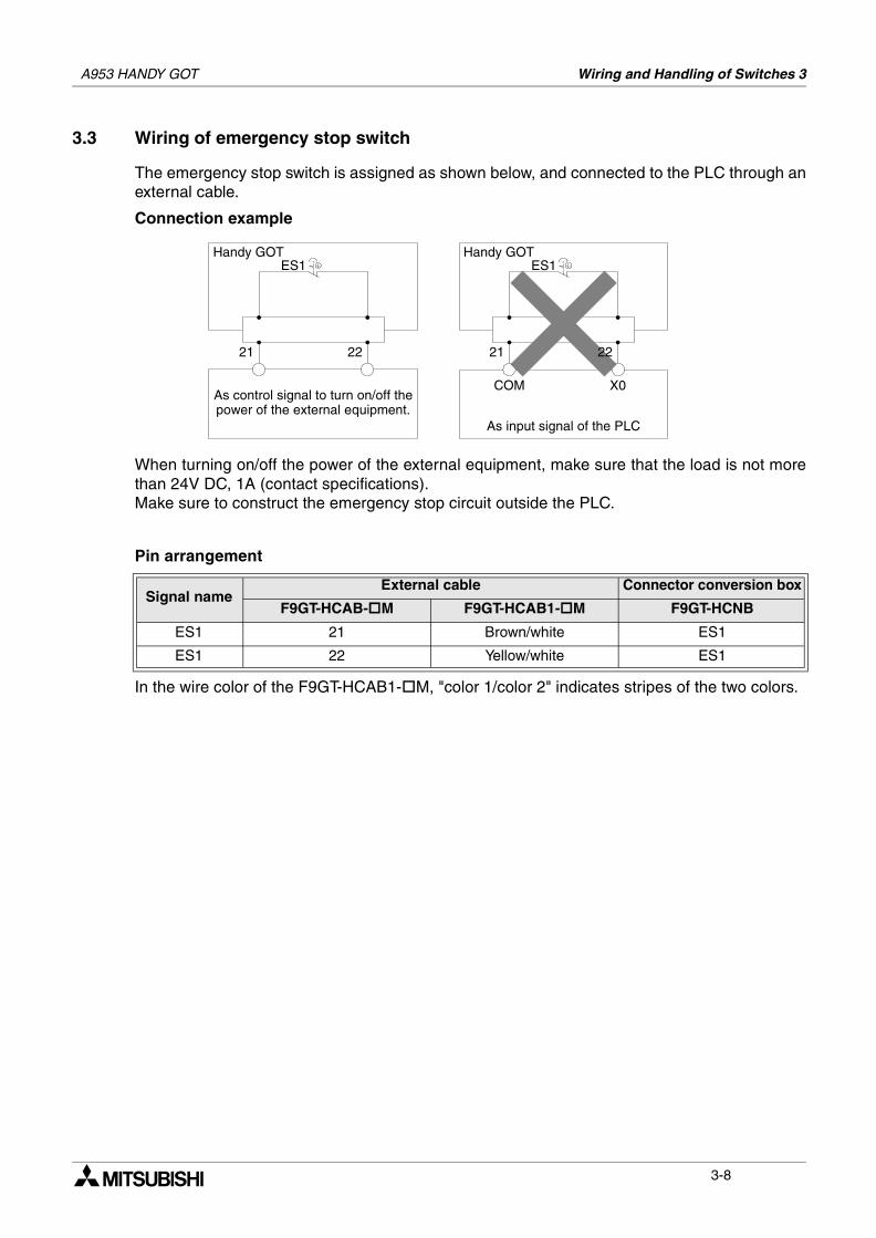
3.3 Wiring of emergency stop switch
The emergency stop switch is assigned as shown below, and connected to the PLC through anexternal cable.
Connection example
When turning on/off the power of the external equipment, make sure that the load is not morethan 24V DC, 1A (contact specifications).Make sure to construct the emergency stop circuit outside the PLC.
Pin arrangement
In the wire color of the F9GT-HCAB1- M, "color 1/color 2" indicates stripes of the two colors.
Signal nameExternal cable Connector conversion box
F9GT-HCAB- M F9GT-HCAB1- M F9GT-HCNB
ES1 21 Brown/white ES1
ES1 22 Yellow/white ES1
As input signal of the PLC
As control signal to turn on/off thepower of the external equipment.
ES1
21
COM X0
ES1
21 22
Handy GOTHandy GOT
22
3-8
A953 HANDY GOT Wiring and Handling of Switches 3
1
2
3
4
5
6
7
8
9
10
11
12
13
14
A
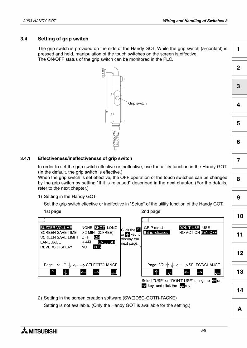
3.4 Setting of grip switch
The grip switch is provided on the side of the Handy GOT. While the grip switch (a-contact) ispressed and held, manipulation of the touch switches on the screen is effective.The ON/OFF status of the grip switch can be monitored in the PLC.
3.4.1 Effectiveness/ineffectiveness of grip switch
In order to set the grip switch effective or ineffective, use the utility function in the Handy GOT.(In the default, the grip switch is effective.)When the grip switch is set effective, the OFF operation of the touch switches can be changedby the grip switch by setting "If it is released" described in the next chapter. (For the details,refer to the next chapter.)
1) Setting in the Handy GOT
Set the grip switch effective or ineffective in "Setup" of the utility function of the Handy GOT.
1st page 2nd page
2) Setting in the screen creation software (SW D5C-GOTR-PACKE)
Setting is not available. (Only the Handy GOT is available for the setting.)
3-9
A953 HANDY GOT Wiring and Handling of Switches 3
3.4.2 Grip switch operation timing
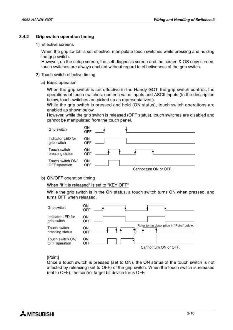
1) Effective screens
When the grip switch is set effective, manipulate touch switches while pressing and holdingthe grip switch.However, on the setup screen, the self-diagnosis screen and the screen & OS copy screen,touch switches are always enabled without regard to effectiveness of the grip switch.
2) Touch switch effective timing
a) Basic operation
When the grip switch is set effective in the Handy GOT, the grip switch controls theoperations of touch switches, numeric value inputs and ASCII inputs (In the descriptionbelow, touch switches are picked up as representatives.).While the grip switch is pressed and held (ON status), touch switch operations areenabled as shown below.However, while the grip switch is released (OFF status), touch switches are disabled andcannot be manipulated from the touch panel.
b) ON/OFF operation timing
When "If it is released" is set to "KEY OFF"
While the grip switch is in the ON status, a touch switch turns ON when pressed, andturns OFF when released.
[Point]Once a touch switch is pressed (set to ON), the ON status of the touch switch is notaffected by releasing (set to OFF) of the grip switch. When the touch switch is released(set to OFF), the control target bit device turns OFF.
Grip switch ONOFF
Touch switchpressing status
Touch switch ON/OFF operation
ONOFF
ONOFF
Cannot turn ON or OFF.
Indicator LED forgrip switch
ONOFF
ONOFF
ONOFF
ONOFF
Cannot turn ON or OFF.
ONOFF
Refer to the description in "Point" below.
Grip switch
Touch switch ON/OFF operation
Indicator LED forgrip switch
Touch switchpressing status
3-10
A953 HANDY GOT Wiring and Handling of Switches 3
1
2
3
4
5
6
7
8
9
10
11
12
13
14
A
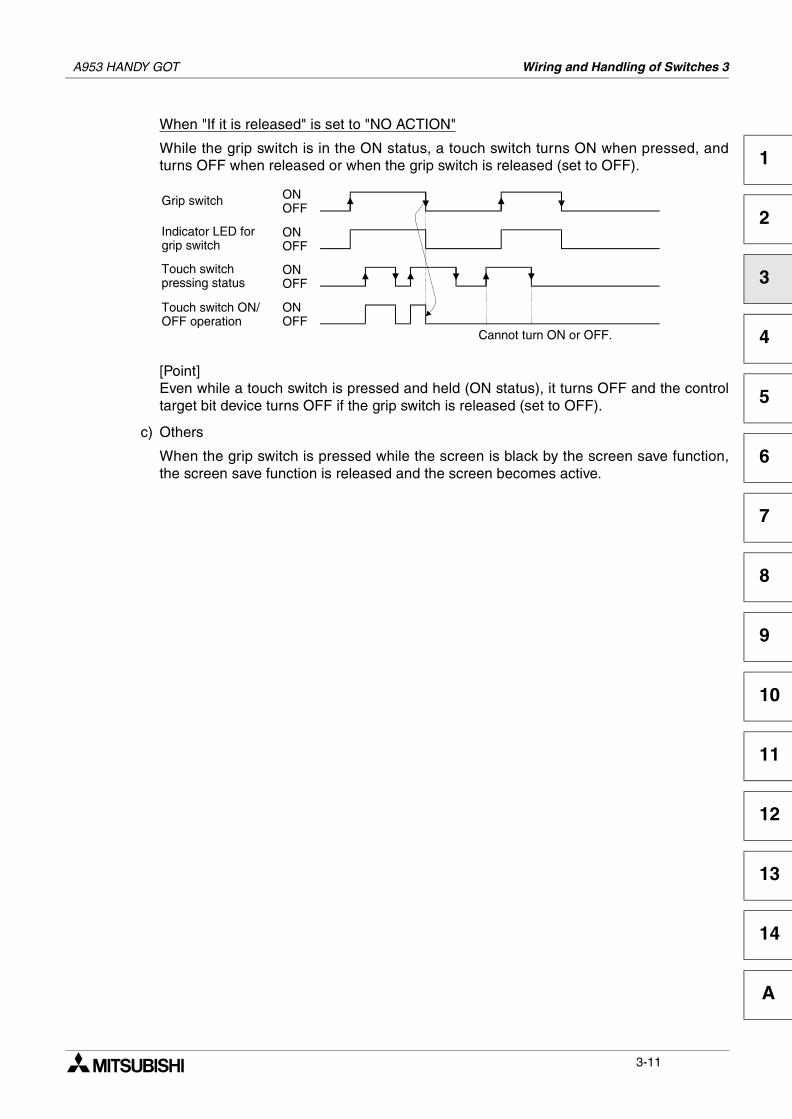
When "If it is released" is set to "NO ACTION"
While the grip switch is in the ON status, a touch switch turns ON when pressed, andturns OFF when released or when the grip switch is released (set to OFF).
[Point]Even while a touch switch is pressed and held (ON status), it turns OFF and the controltarget bit device turns OFF if the grip switch is released (set to OFF).
c) Others
When the grip switch is pressed while the screen is black by the screen save function,the screen save function is released and the screen becomes active.
ONOFF
ONOFF
ONOFF
Cannot turn ON or OFF.
ONOFF
Grip switch
Touch switch ON/OFF operation
Indicator LED forgrip switch
Touch switchpressing status
3-11
A953 HANDY GOT Wiring and Handling of Switches 3
3.4.3 Communication with PLC
In the PLC, the ON/OFF status of the grip switch can be confirmed using the bit device set asfollows. In the Handy GOT, the green GRIP SW LED provided on the front face lights when the gripswitch is pressed.
1) Assigning a device used to confirm the grip switch ON/OFF status
The device used to confirm the grip switch ON/OFF status can be assigned using thescreen creation software.When "Common" is selected then "System Information" is set, the set "Write device" +0 (thesystem signal 2 area) is assigned to the grip switch.The figure below shows the relationship between the bits in the system signal area and thegrip switch.When the bit value is "1", the grip switch is ON. When the bit value is "0", the grip switch isOFF.
System signal 2 area
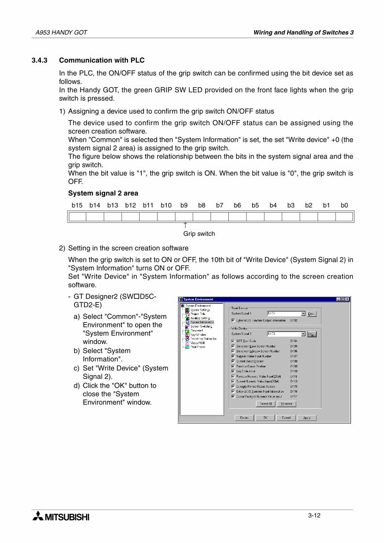
2) Setting in the screen creation software
When the grip switch is set to ON or OFF, the 10th bit of "Write Device" (System Signal 2) in"System Information" turns ON or OFF.Set "Write Device" in "System Information" as follows according to the screen creationsoftware.
- GT Designer2 (SW D5C-GTD2-E)
a) Select "Common"-"System Environment" to open the "System Environment" window.
b) Select "System Information".
c) Set "Write Device" (System Signal 2).
d) Click the "OK" button to close the "System Environment" window.
b15 b14 b13 b12 b11 b10 b9 b8 b7 b6 b5 b4 b3 b2 b1 b0
↑Grip switch
3-12
A953 HANDY GOT Wiring and Handling of Switches 3
1
2
3
4
5
6
7
8
9
10
11
12
13
14
A
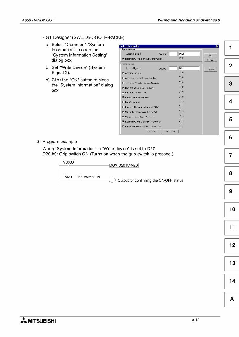
- GT Designer (SW D5C-GOTR-PACKE)
a) Select "Common"-"System Information" to open the "System Information Setting" dialog box.
b) Set "Write Device" (System Signal 2).
c) Click the "OK" button to close the "System Information" dialog box.
3) Program example
When "System Information" in "Write device" is set to D20D20 b9: Grip switch ON (Turns on when the grip switch is pressed.)
M29 Grip switch ONOutput for confirming the ON/OFF status
M8000MOV D20 K4M20
3-13
A953 HANDY GOT Wiring and Handling of Switches 3
3.5 Creation of operation switch name sheet
This section describes how to create the operation switch name sheet.
3.5.1 Creation of name sheet
1) Prepare a mount sheet and an OHP sheet (transparent sheet) offered as accessories.
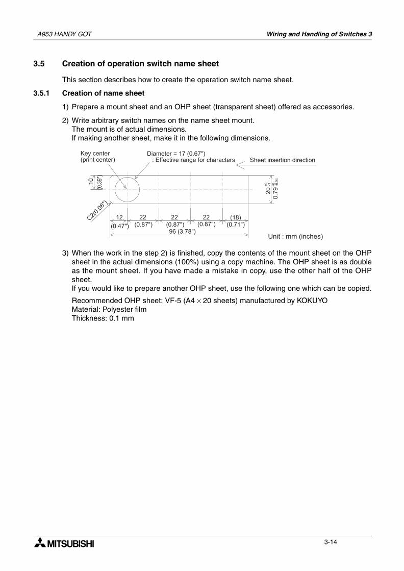
2) Write arbitrary switch names on the name sheet mount.The mount is of actual dimensions.If making another sheet, make it in the following dimensions.
3) When the work in the step 2) is finished, copy the contents of the mount sheet on the OHPsheet in the actual dimensions (100%) using a copy machine. The OHP sheet is as doubleas the mount sheet. If you have made a mistake in copy, use the other half of the OHPsheet.If you would like to prepare another OHP sheet, use the following one which can be copied.
Recommended OHP sheet: VF-5 (A4 × 20 sheets) manufactured by KOKUYOMaterial: Polyester filmThickness: 0.1 mm
! " # $ % % & ' %
(
(
) # ! !
3-14
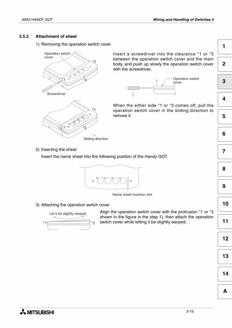
A953 HANDY GOT Wiring and Handling of Switches 3
1
2
3
4
5
6
7
8
9
10
11
12
13
14
A
3.5.2 Attachment of sheet
1) Removing the operation switch cover
Inser t a screwdriver into the clearance *1 or *3between the operation switch cover and the mainbody, and push up slowly the operation switch coverwith the screwdriver.
When the either side *1 or *3 comes off, pull theoperation switch cover in the sliding direction toremove it.
2) Inserting the sheet
Insert the name sheet into the following position of the Handy GOT.
3) Attaching the operation switch cover
Align the operation switch cover with the protrusion *1 or *3shown in the figure in the step 1), then attach the operationswitch cover while letting it be slightly warped.
* + &
, ,
,
+ &
- '
,
,
,
* + &
. ! -
, ,
/ 0 - ' - +
3-15
A953 HANDY GOT Wiring and Handling of Switches 3
MEMO
3-16
Specifications 4
1
2
3
4
5
6
7
8
9
10
11
12
13
14
A
4. Specifications
Caution on design
• While executing monitoring in the GOT (GOT-F900), if a communication error (includingdisconnection of a cable) occurs, communication between the GOT and the PLC CPU isinterrupted and the GOT is disabled.When establishing the system configuration using the GOT, make sure that a switchwhich gives a significant operation to the system is executed from any equipment otherthan the GOT while postulating communication error in the GOT. Otherwise, accidentsmay be caused by incorrect output and malfunction.
Cautions on design
• Do not bind the control cable and the communication cable together with the main circuitand the power line. Keep such cables off the main circuit and the power line by 100mm(3.94") or more.Otherwise, malfunction may be caused by noise.
• Make sure to press touch keys on the display screen with hand. If touch keys are subjectto an excessive force or pressed by a hard or sharp object, they may fail.
Cautions on startup/maintenance
• Do not touch connectors while the power is ON.If a connector is touched, electrical shock or malfunction may be caused.
• Set to OFF the power before cleaning the Handy GOT or tightening a terminal.If the Handy GOT is cleaned or a terminal is tightened while the power is ON, you may getelectrical shock.
Cautions on startup/maintenance
• Do not disassemble or modify the Handy GOT.Disassembly or modification may cause failure, malfunction or fire.
• For replacement or repair of the backlight, consult with a Mitsubishi Electric distributor.
• Turn OFF the power before connecting or disconnecting a cable.Connecting or disconnecting a cable while the power is ON may cause failure ormalfunction.
Caution on disposal
• When disposing of the Handy GOT, treat it as industrial waste.
A953 HANDY GOT
4-1
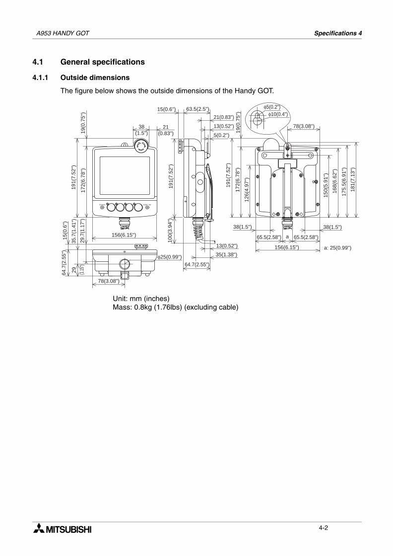
A953 HANDY GOT Specifications 4
4.1 General specifications
4.1.1 Outside dimensions
The figure below shows the outside dimensions of the Handy GOT.
Unit: mm (inches)Mass: 0.8kg (1.76lbs) (excluding cable)
GRIPPOWER SW
191(
7.52
")
172(
6.78
")29
.7(1
.17"
)35
.7(1
.41"
)
64.7
(2.5
5")
15(0
.6")
100(
3.94
")
191(
7.52
")
150(
5.91
")
168(
6.62
")
175.
5(6.
91")
181(
7.13
")
172(
6.78
")
126(
4.97
")19
(0.7
5")
191(
7.52
")
29
19(0
.75"
)
38(1.5")
156(6.15")
78(3.08")
φ25(0.99")64.7(2.55")
35(1.38")
13(0.52")
21(0.83")
21(0.83")
38(1.5") 38(1.5")
a
156(6.15")
65.5(2.58") 65.5(2.58")
78(3.08")13(0.52")
5(0.2")
15(0.6") 63.5(2.5")
(1.15
")
a: 25(0.99")
φ10(0.4")φ5(0.2")
4-2
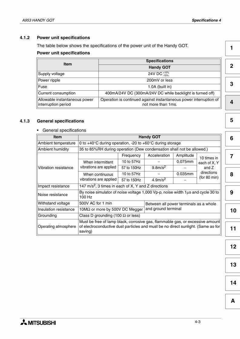
A953 HANDY GOT Specifications 4
1
2
3
4
5
6
7
8
9
10
11
12
13
14
A
4.1.2 Power unit specifications
The table below shows the specifications of the power unit of the Handy GOT.
Power unit specifications
4.1.3 General specifications
• General specifications
ItemSpecifications
Handy GOT
Supply voltage 24V DC
Power ripple 200mV or less
Fuse 1.0A (built in)
Current consumption 400mA/24V DC (300mA/24V DC while backlight is turned off)
Allowable instantaneous power interruption period
Operation is continued against instantaneous power interruption of not more than 1ms.
Item Handy GOT
Ambient temperature 0 to +40°C during operation, -20 to +60°C during storage
Ambient humidity 35 to 85%RH during operation (Dew condensation shall not be allowed.)
Vibration resistance
Frequency Acceleration Amplitude10 times in
each of X, Y and Z
directions (for 80 min)
When intermittent vibrations are applied
10 to 57Hz − 0.075mm
57 to 150Hz 9.8m/s2 −
When continuous vibrations are applied
10 to 57Hz − 0.035mm
57 to 150Hz 4.9m/s2 −Impact resistance 147 m/s2, 3 times in each of X, Y and Z directions
Noise resistanceBy noise simulator of noise voltage 1,000 Vp-p, noise width 1µs and cycle 30 to 100 Hz
Withstand voltage 500V AC for 1 min Between all power terminals as a whole and ground terminalInsulation resistance 10MΩ or more by 500V DC Megger
Grounding Class D grounding (100 Ω or less)
Operating atmosphereMust be free of lamp black, corrosive gas, flammable gas, or excessive amountof electroconductive dust particles and must be no direct sunlight. (Same as forsaving)
+10%-15%
4-3
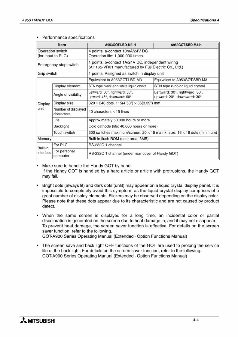
A953 HANDY GOT Specifications 4
• Performance specifications
• Make sure to handle the Handy GOT by hand.If the Handy GOT is handled by a hard article or article with protrusions, the Handy GOTmay fail.
• Bright dots (always lit) and dark dots (unlit) may appear on a liquid crystal display panel. It isimpossible to completely avoid this symptom, as the liquid crystal display comprises of agreat number of display elements. Flickers may be observed depending on the display color.Please note that these dots appear due to its characteristic and are not caused by productdefect.
• When the same screen is displayed for a long time, an incidental color or partialdiscoloration is generated on the screen due to heat damage in, and it may not disappear.To prevent heat damage, the screen saver function is effective. For details on the screensaver function, refer to the following.GOT-A900 Series Operating Manual (Extended ⋅ Option Functions Manual)
• The screen save and back light OFF functions of the GOT are used to prolong the servicelife of the back light. For details on the screen saver function, refer to the following.GOT-A900 Series Operating Manual (Extended ⋅ Option Functions Manual)
Item A953GOT-LBD-M3-H A953GOT-SBD-M3-H
Operation switch (for input to PLC)
4 points, a-contact 10mA/24V DCOperation life: 1,000,000 times
Emergency stop switch1 points, b-contact 1A/24V DC, independent wiring(AH165-VR01 manufactured by Fuji Electric Co., Ltd.)
Grip switch 1 points, Assigned as switch in display unit
Displayunit
Equivalent to A953GOT-LBD-M3 Equivalent to A953GOT-SBD-M3
Display element STN type black-and-white liquid crystal STN type 8-color liquid crystal
Angle of visibilityLeftward: 50°, rightward: 50°, upward: 45°, downward: 60°
Leftward: 30°, rightward: 30°, upward: 20°, downward: 30°
Display size 320 × 240 dots, 115(4.53") × 86(3.39") mm
Number of displayed characters
40 characters × 15 lines
Life Approximately 50,000 hours or more
Backlight Cold cathode (life: 40,000 hours or more)
Touch switch 300 switches maximum/screen, 20 × 15 matrix, size: 16 × 16 dots (minimum)
Memory Built-in flush ROM (user area: 3MB)
Built-in interface
For PLC RS-232C 1 channel
For personal computer
RS-232C 1 channel (under rear cover of Handy GOT)
4-4
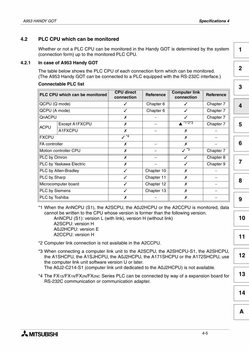
A953 HANDY GOT Specifications 4
1
2
3
4
5
6
7
8
9
10
11
12
13
14
A
4.2 PLC CPU which can be monitored
Whether or not a PLC CPU can be monitored in the Handy GOT is determined by the system(connection form) up to the monitored PLC CPU.
4.2.1 In case of A953 Handy GOT
The table below shows the PLC CPU of each connection form which can be monitored.(The A953 Handy GOT can be connected to a PLC equipped with the RS-232C interface.)
Connectable PLC list
*1 When the AnNCPU (S1), the A2SCPU, the A0J2HCPU or the A2CCPU is monitored, datacannot be written to the CPU whose version is former than the following version.
AnNCPU (S1): version L (with link), version H (without link)A2SCPU: version HA0J2HCPU: version EA2CCPU: version H
*2 Computer link connection is not available in the A2CCPU.
*3 When connecting a computer link unit to the A2SCPU, the A2SHCPU-S1, the A2SHCPU,the A1SHCPU, the A1SJHCPU, the A0J2HCPU, the A171SHCPU or the A172SHCPU, usethe computer link unit software version U or later.The A0J2-C214-S1 (computer link unit dedicated to the A0J2HCPU) is not available.
*4 The FX1S/FX1N/FX2N/FX2NC Series PLC can be connected by way of a expansion board forRS-232C communication or communication adapter.
PLC CPU which can be monitoredCPU directconnection
ReferenceComputer link
connectionReference
QCPU (Q mode) Chapter 6 Chapter 7
QCPU (A mode) Chapter 6 Chapter 7
QnACPU − Chapter 7
ACPUExcept A1FXCPU − *1*2*3 Chapter 7
A1FXCPU − −FXCPU *4 −FA controller − −Motion controller CPU − *3 Chapter 7
PLC by Omron − Chapter 8
PLC by Yaskawa Electric − Chapter 9
PLC by Allen-Bradley Chapter 10 −PLC by Sharp Chapter 11 −Microcomputer board Chapter 12 −PLC by Siemens Chapter 13 −PLC by Toshiba − −
4-5
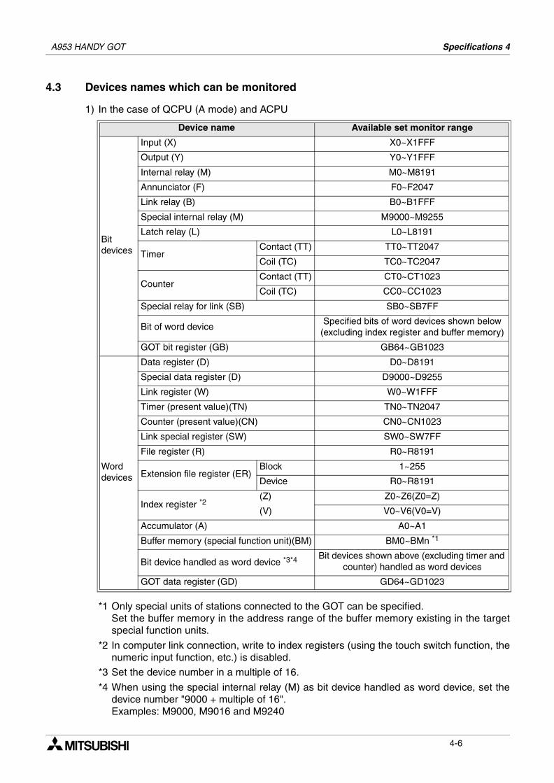
A953 HANDY GOT Specifications 4
4.3 Devices names which can be monitored
1) In the case of QCPU (A mode) and ACPU
*1 Only special units of stations connected to the GOT can be specified.Set the buffer memory in the address range of the buffer memory existing in the targetspecial function units.
*2 In computer link connection, write to index registers (using the touch switch function, thenumeric input function, etc.) is disabled.
*3 Set the device number in a multiple of 16.
*4 When using the special internal relay (M) as bit device handled as word device, set thedevice number "9000 + multiple of 16".Examples: M9000, M9016 and M9240
Device name Available set monitor range
Bitdevices
Input (X) X0~X1FFF
Output (Y) Y0~Y1FFF
Internal relay (M) M0~M8191
Annunciator (F) F0~F2047
Link relay (B) B0~B1FFF
Special internal relay (M) M9000~M9255
Latch relay (L) L0~L8191
TimerContact (TT) TT0~TT2047
Coil (TC) TC0~TC2047
CounterContact (TT) CT0~CT1023
Coil (TC) CC0~CC1023
Special relay for link (SB) SB0~SB7FF
Bit of word deviceSpecified bits of word devices shown below
(excluding index register and buffer memory)
GOT bit register (GB) GB64~GB1023
Worddevices
Data register (D) D0~D8191
Special data register (D) D9000~D9255
Link register (W) W0~W1FFF
Timer (present value)(TN) TN0~TN2047
Counter (present value)(CN) CN0~CN1023
Link special register (SW) SW0~SW7FF
File register (R) R0~R8191
Extension file register (ER)Block 1~255
Device R0~R8191
Index register *2(Z) Z0~Z6(Z0=Z)
(V) V0~V6(V0=V)
Accumulator (A) A0~A1
Buffer memory (special function unit)(BM) BM0~BMn *1
Bit device handled as word device *3*4 Bit devices shown above (excluding timer and counter) handled as word devices
GOT data register (GD) GD64~GD1023
4-6
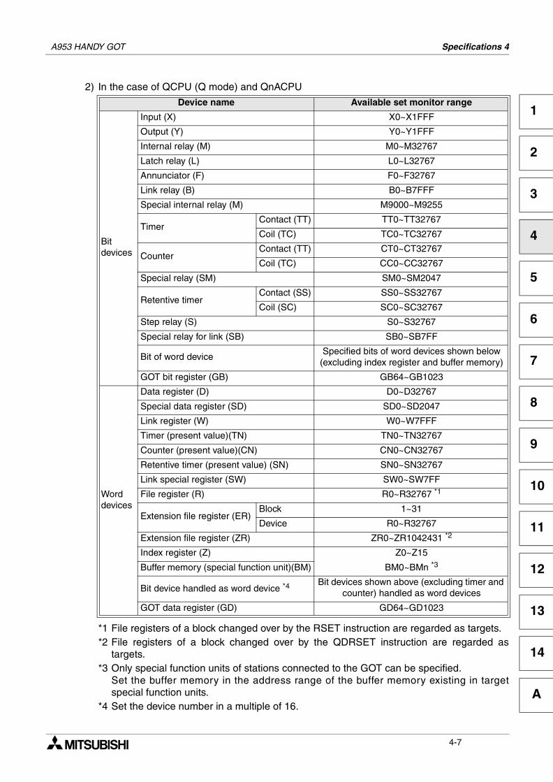
A953 HANDY GOT Specifications 4
1
2
3
4
5
6
7
8
9
10
11
12
13
14
A
2) In the case of QCPU (Q mode) and QnACPU
*1 File registers of a block changed over by the RSET instruction are regarded as targets.*2 File registers of a block changed over by the QDRSET instruction are regarded as
targets.*3 Only special function units of stations connected to the GOT can be specified.
Set the buffer memory in the address range of the buffer memory existing in targetspecial function units.
*4 Set the device number in a multiple of 16.
Device name Available set monitor range
Bitdevices
Input (X) X0~X1FFF
Output (Y) Y0~Y1FFF
Internal relay (M) M0~M32767
Latch relay (L) L0~L32767
Annunciator (F) F0~F32767
Link relay (B) B0~B7FFF
Special internal relay (M) M9000~M9255
TimerContact (TT) TT0~TT32767
Coil (TC) TC0~TC32767
CounterContact (TT) CT0~CT32767
Coil (TC) CC0~CC32767
Special relay (SM) SM0~SM2047
Retentive timerContact (SS) SS0~SS32767
Coil (SC) SC0~SC32767
Step relay (S) S0~S32767
Special relay for link (SB) SB0~SB7FF
Bit of word deviceSpecified bits of word devices shown below
(excluding index register and buffer memory)
GOT bit register (GB) GB64~GB1023
Worddevices
Data register (D) D0~D32767
Special data register (SD) SD0~SD2047
Link register (W) W0~W7FFF
Timer (present value)(TN) TN0~TN32767
Counter (present value)(CN) CN0~CN32767
Retentive timer (present value) (SN) SN0~SN32767
Link special register (SW) SW0~SW7FF
File register (R) R0~R32767 *1
Extension file register (ER)Block 1~31
Device R0~R32767
Extension file register (ZR) ZR0~ZR1042431 *2
Index register (Z) Z0~Z15
Buffer memory (special function unit)(BM) BM0~BMn *3
Bit device handled as word device *4Bit devices shown above (excluding timer and
counter) handled as word devices
GOT data register (GD) GD64~GD1023
4-7
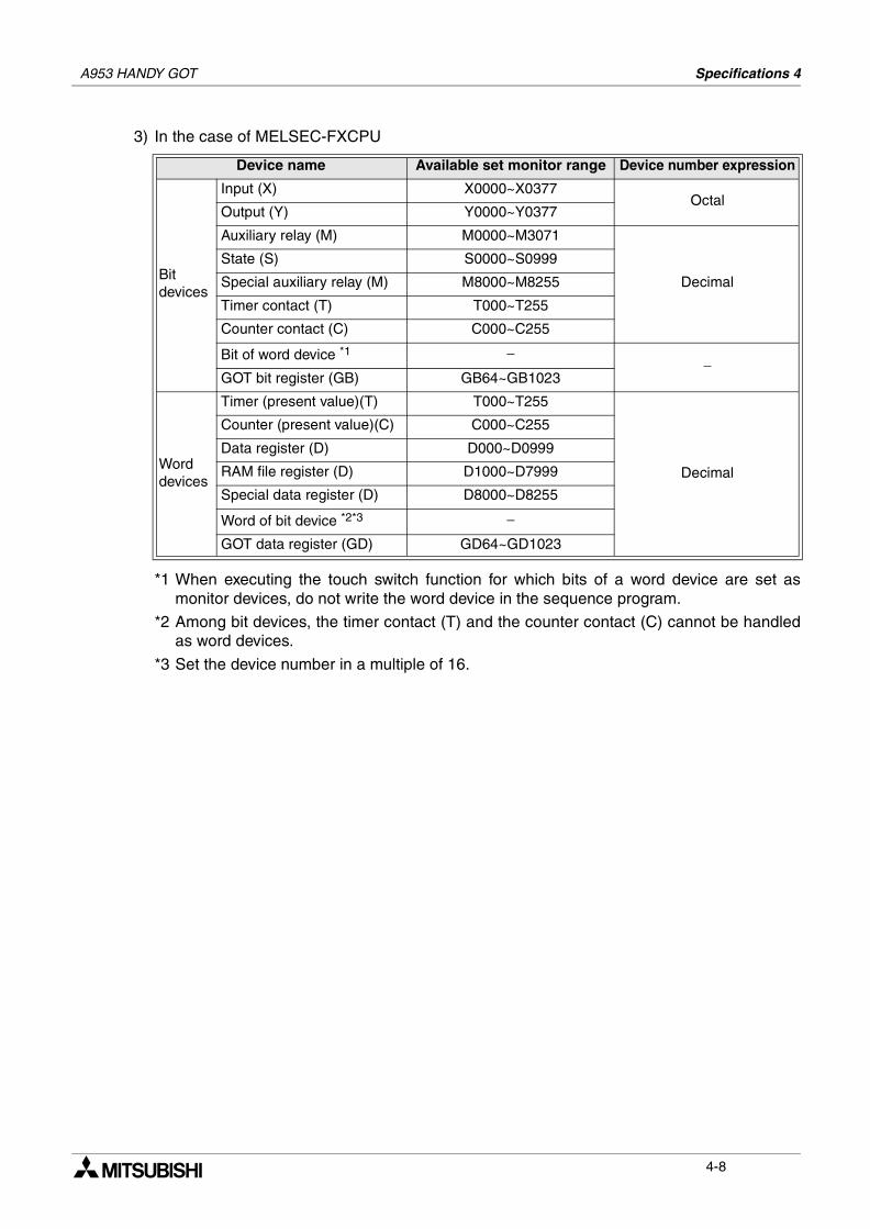
A953 HANDY GOT Specifications 4
3) In the case of MELSEC-FXCPU
*1 When executing the touch switch function for which bits of a word device are set asmonitor devices, do not write the word device in the sequence program.
*2 Among bit devices, the timer contact (T) and the counter contact (C) cannot be handledas word devices.
*3 Set the device number in a multiple of 16.
Device name Available set monitor range Device number expression
Bitdevices
Input (X) X0000~X0377Octal
Output (Y) Y0000~Y0377
Auxiliary relay (M) M0000~M3071
Decimal
State (S) S0000~S0999
Special auxiliary relay (M) M8000~M8255
Timer contact (T) T000~T255
Counter contact (C) C000~C255
Bit of word device *1 −−
GOT bit register (GB) GB64~GB1023
Worddevices
Timer (present value)(T) T000~T255
Decimal
Counter (present value)(C) C000~C255
Data register (D) D000~D0999
RAM file register (D) D1000~D7999
Special data register (D) D8000~D8255
Word of bit device *2*3 −
GOT data register (GD) GD64~GD1023
4-8
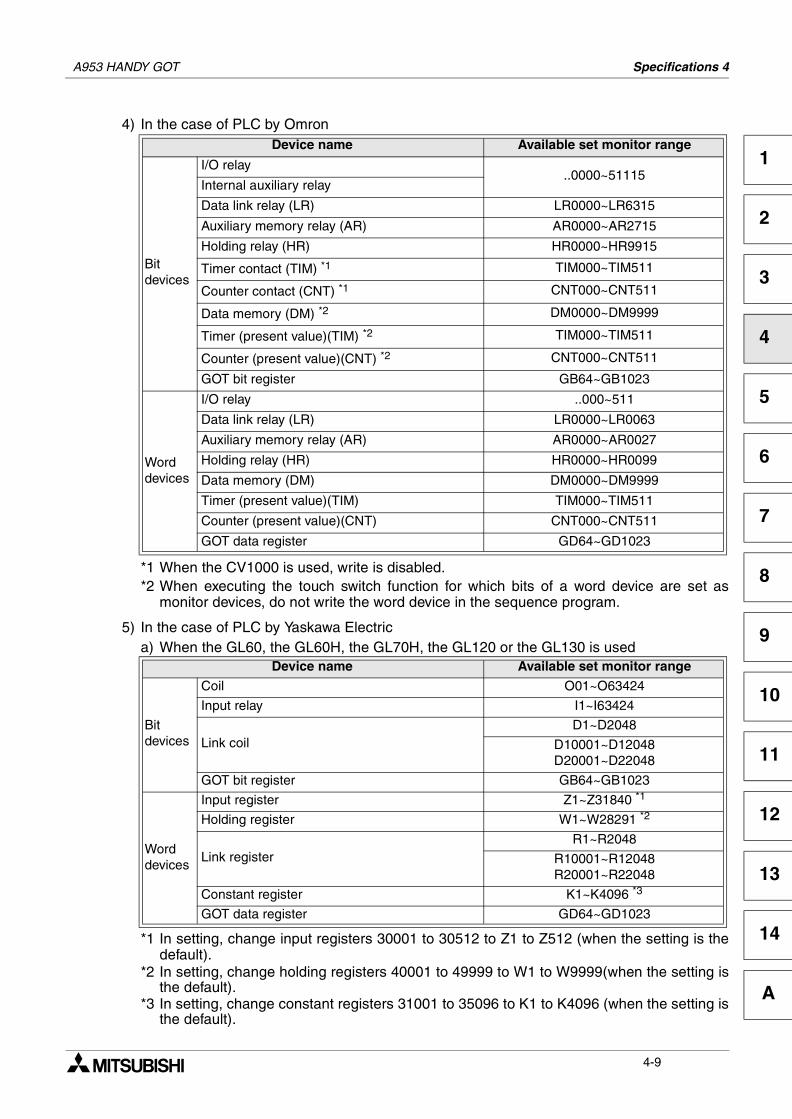
A953 HANDY GOT Specifications 4
1
2
3
4
5
6
7
8
9
10
11
12
13
14
A
4) In the case of PLC by Omron
*1 When the CV1000 is used, write is disabled.*2 When executing the touch switch function for which bits of a word device are set as
monitor devices, do not write the word device in the sequence program.
5) In the case of PLC by Yaskawa Electrica) When the GL60, the GL60H, the GL70H, the GL120 or the GL130 is used
*1 In setting, change input registers 30001 to 30512 to Z1 to Z512 (when the setting is thedefault).
*2 In setting, change holding registers 40001 to 49999 to W1 to W9999(when the setting isthe default).
*3 In setting, change constant registers 31001 to 35096 to K1 to K4096 (when the setting isthe default).
Device name Available set monitor range
Bitdevices
I/O relay..0000~51115
Internal auxiliary relay
Data link relay (LR) LR0000~LR6315
Auxiliary memory relay (AR) AR0000~AR2715
Holding relay (HR) HR0000~HR9915
Timer contact (TIM) *1 TIM000~TIM511
Counter contact (CNT) *1 CNT000~CNT511
Data memory (DM) *2 DM0000~DM9999
Timer (present value)(TIM) *2 TIM000~TIM511
Counter (present value)(CNT) *2 CNT000~CNT511
GOT bit register GB64~GB1023
Worddevices
I/O relay ..000~511
Data link relay (LR) LR0000~LR0063
Auxiliary memory relay (AR) AR0000~AR0027
Holding relay (HR) HR0000~HR0099
Data memory (DM) DM0000~DM9999
Timer (present value)(TIM) TIM000~TIM511
Counter (present value)(CNT) CNT000~CNT511
GOT data register GD64~GD1023
Device name Available set monitor range
Bitdevices
Coil O01~O63424
Input relay I1~I63424
Link coilD1~D2048
D10001~D12048D20001~D22048
GOT bit register GB64~GB1023
Worddevices
Input register Z1~Z31840 *1
Holding register W1~W28291 *2
Link registerR1~R2048
R10001~R12048R20001~R22048
Constant register K1~K4096 *3
GOT data register GD64~GD1023
4-9
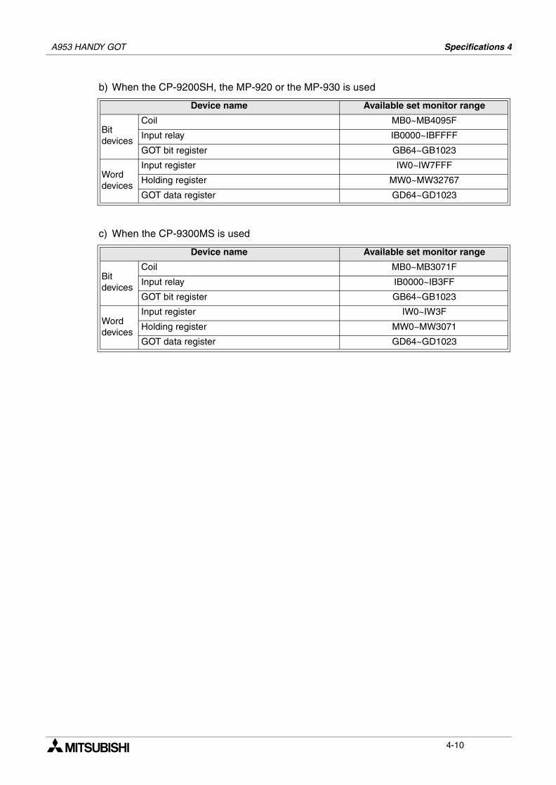
A953 HANDY GOT Specifications 4
b) When the CP-9200SH, the MP-920 or the MP-930 is used
c) When the CP-9300MS is used
Device name Available set monitor range
Bitdevices
Coil MB0~MB4095F
Input relay IB0000~IBFFFF
GOT bit register GB64~GB1023
Worddevices
Input register IW0~IW7FFF
Holding register MW0~MW32767
GOT data register GD64~GD1023
Device name Available set monitor range
Bitdevices
Coil MB0~MB3071F
Input relay IB0000~IB3FF
GOT bit register GB64~GB1023
Worddevices
Input register IW0~IW3F
Holding register MW0~MW3071
GOT data register GD64~GD1023
4-10
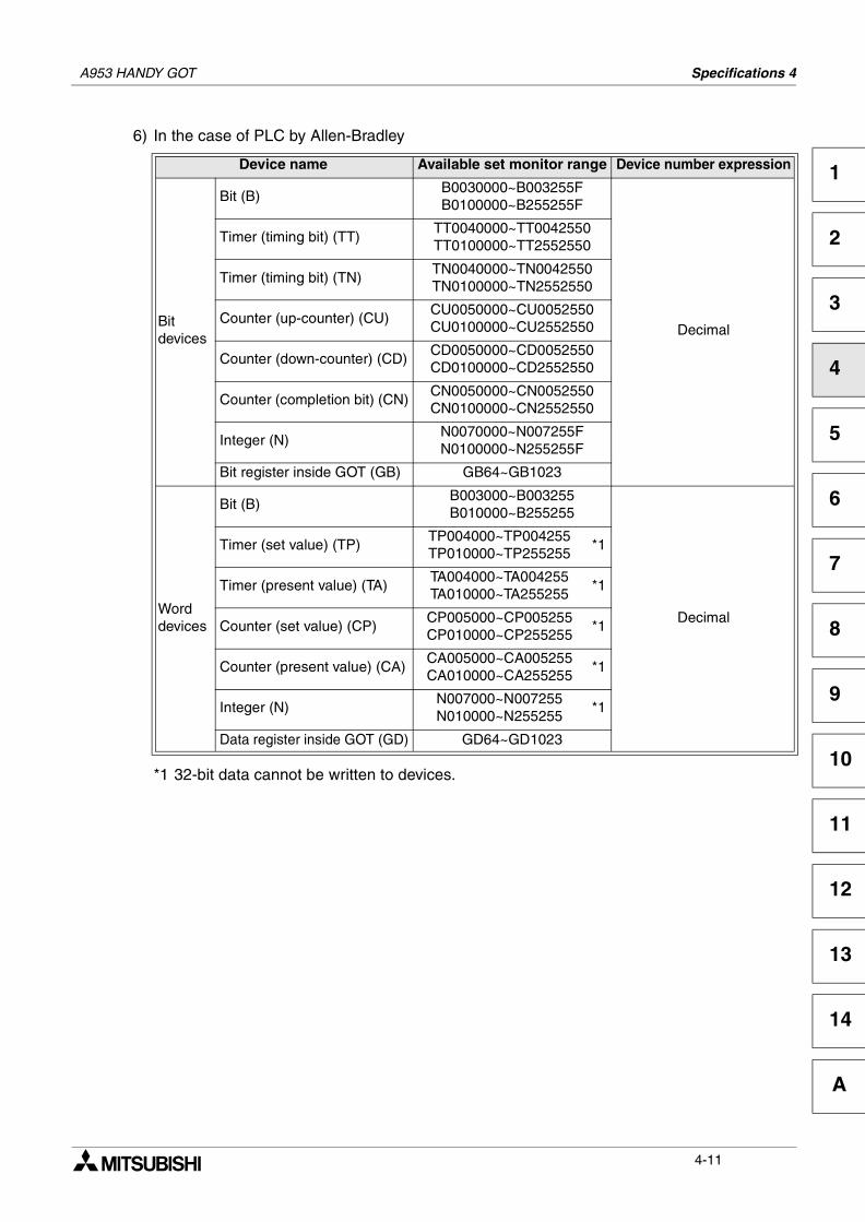
A953 HANDY GOT Specifications 4
1
2
3
4
5
6
7
8
9
10
11
12
13
14
A
6) In the case of PLC by Allen-Bradley
*1 32-bit data cannot be written to devices.
Device name Available set monitor range Device number expression
Bitdevices
Bit (B)B0030000~B003255FB0100000~B255255F
Decimal
Timer (timing bit) (TT)TT0040000~TT0042550TT0100000~TT2552550
Timer (timing bit) (TN)TN0040000~TN0042550TN0100000~TN2552550
Counter (up-counter) (CU)CU0050000~CU0052550CU0100000~CU2552550
Counter (down-counter) (CD)CD0050000~CD0052550CD0100000~CD2552550
Counter (completion bit) (CN)CN0050000~CN0052550CN0100000~CN2552550
Integer (N)N0070000~N007255FN0100000~N255255F
Bit register inside GOT (GB) GB64~GB1023
Worddevices
Bit (B)B003000~B003255B010000~B255255
Decimal
Timer (set value) (TP)TP004000~TP004255TP010000~TP255255
*1
Timer (present value) (TA)TA004000~TA004255TA010000~TA255255
*1
Counter (set value) (CP)CP005000~CP005255CP010000~CP255255
*1
Counter (present value) (CA)CA005000~CA005255CA010000~CA255255
*1
Integer (N)N007000~N007255N010000~N255255
*1
Data register inside GOT (GD) GD64~GD1023
4-11
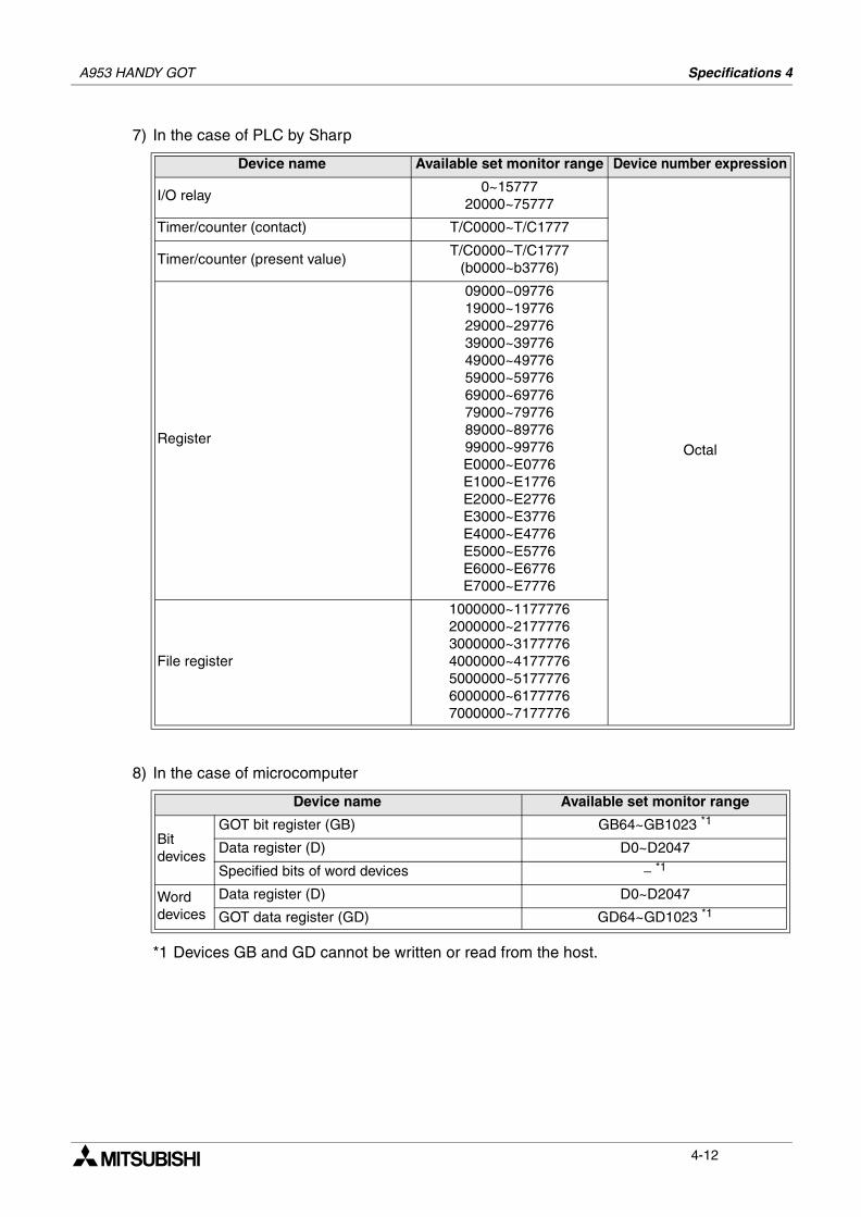
A953 HANDY GOT Specifications 4
7) In the case of PLC by Sharp
8) In the case of microcomputer
*1 Devices GB and GD cannot be written or read from the host.
Device name Available set monitor range Device number expression
I/O relay0~15777
20000~75777
Octal
Timer/counter (contact) T/C0000~T/C1777
Timer/counter (present value)T/C0000~T/C1777
(b0000~b3776)
Register
09000~0977619000~1977629000~2977639000~3977649000~4977659000~5977669000~6977679000~7977689000~8977699000~99776E0000~E0776E1000~E1776E2000~E2776E3000~E3776E4000~E4776E5000~E5776E6000~E6776E7000~E7776
File register
1000000~11777762000000~21777763000000~31777764000000~41777765000000~51777766000000~61777767000000~7177776
Device name Available set monitor range
Bitdevices
GOT bit register (GB) GB64~GB1023 *1
Data register (D) D0~D2047
Specified bits of word devices − *1
Worddevices
Data register (D) D0~D2047
GOT data register (GD) GD64~GD1023 *1
4-12
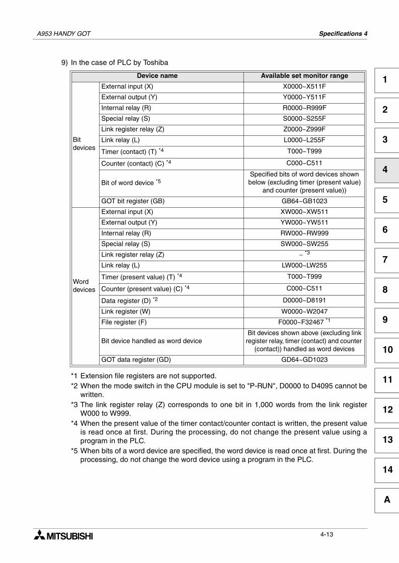
A953 HANDY GOT Specifications 4
1
2
3
4
5
6
7
8
9
10
11
12
13
14
A
9) In the case of PLC by Toshiba
*1 Extension file registers are not supported.*2 When the mode switch in the CPU module is set to "P-RUN", D0000 to D4095 cannot be
written.*3 The link register relay (Z) corresponds to one bit in 1,000 words from the link register
W000 to W999.*4 When the present value of the timer contact/counter contact is written, the present value
is read once at first. During the processing, do not change the present value using aprogram in the PLC.
*5 When bits of a word device are specified, the word device is read once at first. During theprocessing, do not change the word device using a program in the PLC.
Device name Available set monitor range
Bitdevices
External input (X) X0000~X511F
External output (Y) Y0000~Y511F
Internal relay (R) R0000~R999F
Special relay (S) S0000~S255F
Link register relay (Z) Z0000~Z999F
Link relay (L) L0000~L255F
Timer (contact) (T) *4 T000~T999
Counter (contact) (C) *4 C000~C511
Bit of word device *5Specified bits of word devices shown below (excluding timer (present value)
and counter (present value))
GOT bit register (GB) GB64~GB1023
Worddevices
External input (X) XW000~XW511
External output (Y) YW000~YW511
Internal relay (R) RW000~RW999
Special relay (S) SW000~SW255
Link register relay (Z) − *3
Link relay (L) LW000~LW255
Timer (present value) (T) *4 T000~T999
Counter (present value) (C) *4 C000~C511
Data register (D) *2 D0000~D8191
Link register (W) W0000~W2047
File register (F) F0000~F32467 *1
Bit device handled as word deviceBit devices shown above (excluding link
register relay, timer (contact) and counter (contact)) handled as word devices
GOT data register (GD) GD64~GD1023
4-13

A953 HANDY GOT Specifications 4
MEMO
4-14
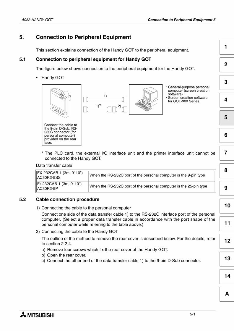
Connection to Peripheral Equipment 5
1
2
3
4
5
6
7
8
9
10
11
12
13
14
A
5. Connection to Peripheral Equipment
This section explains connection of the Handy GOT to the peripheral equipment.
5.1 Connection to peripheral equipment for Handy GOT
The figure below shows connection to the peripheral equipment for the Handy GOT.
• Handy GOT
* The PLC card, the external I/O interface unit and the printer interface unit cannot beconnected to the Handy GOT.
Data transfer cable
5.2 Cable connection procedure
1) Connecting the cable to the personal computer
Connect one side of the data transfer cable 1) to the RS-232C interface port of the personalcomputer. (Select a proper data transfer cable in accordance with the port shape of thepersonal computer while referring to the table above.)
2) Connecting the cable to the Handy GOT
The outline of the method to remove the rear cover is described below. For the details, referto section 2.2.4.a) Remove four screws which fix the rear cover of the Handy GOT.b) Open the rear cover.c) Connect the other end of the data transfer cable 1) to the 9-pin D-Sub connector.
FX-232CAB-1 (3m, 9' 10")AC30R2-9SS
When the RS-232C port of the personal computer is the 9-pin type
F2-232CAB-1 (3m, 9' 10")AC30R2-9P
When the RS-232C port of the personal computer is the 25-pin type
1)
General-purpose personalcomputer (screen creationsoftware)Screen creation softwarefor GOT-900 Series
Connect the cable tothe 9-pin D-Sub, RS-232C connector (forpersonal computer)provided on the rearface.
1)*1 2)
.
.
1 * 2$ 3
4 3 5 1 2
A953 HANDY GOT
5-1
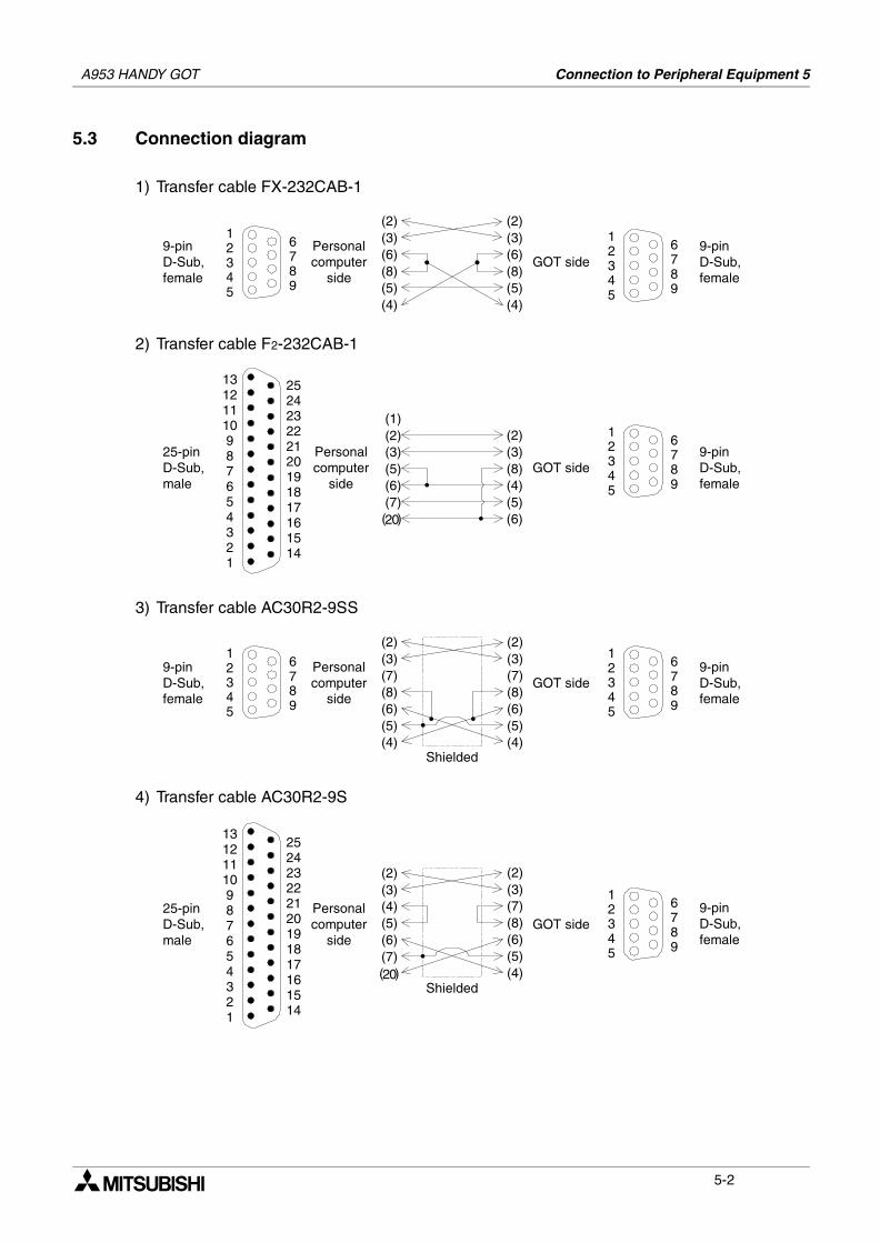
A953 HANDY GOT Connection to Peripheral Equipment 5
5.3 Connection diagram
1) Transfer cable FX-232CAB-1
2) Transfer cable F2-232CAB-1
3) Transfer cable AC30R2-9SS
4) Transfer cable AC30R2-9S
GOT side9-pinD-Sub,female
Personalcomputer
side
9-pinD-Sub,female
12345
6789
12345
6789
(2)(3)(6)(8)(5)
(2)(3)(6)(8)(5)(4) (4)
25-pinD-Sub,male
Personalcomputer
sideGOT side
9-pinD-Sub,female
12345
6789
13121110987654321
252423222120191817161514
(1)(2)(3)
(4)(5)(6)
(8)
(2)(3)(5)
(7)(6)
( )20
GOT side9-pinD-Sub,female
Personalcomputer
side
9-pinD-Sub,female
12345
6789
12345
6789
(2)(3)(7)(8)(6)(5)(4)
Shielded
(2)(3)(7)(8)(6)(5)(4)
GOT sidePersonalcomputer
side
25-pinD-Sub,male
9-pinD-Sub,female
12345
6789
13121110987654321
252423222120191817161514
(2)(3)(4)(5)(6)(7)
Shielded
(2)(3)(7)(8)(6)(5)(4)( )20
5-2
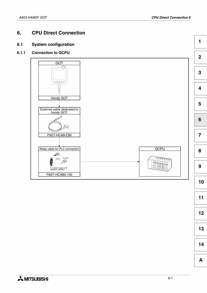
CPU Direct Connection 6
1
2
3
4
5
6
7
8
9
10
11
12
13
14
A
6. CPU Direct Connection
6.1 System configuration
6.1.1 Connection to QCPU
QCPU
GOT
Handy GOT
External cable dedicated tohandy GOT
F9GT-HCAB- M
Relay cable for PLC connection
F9GT-HCAB5-150
To PLC
For power supply andoperation switches
A953 HANDY GOT
6-1
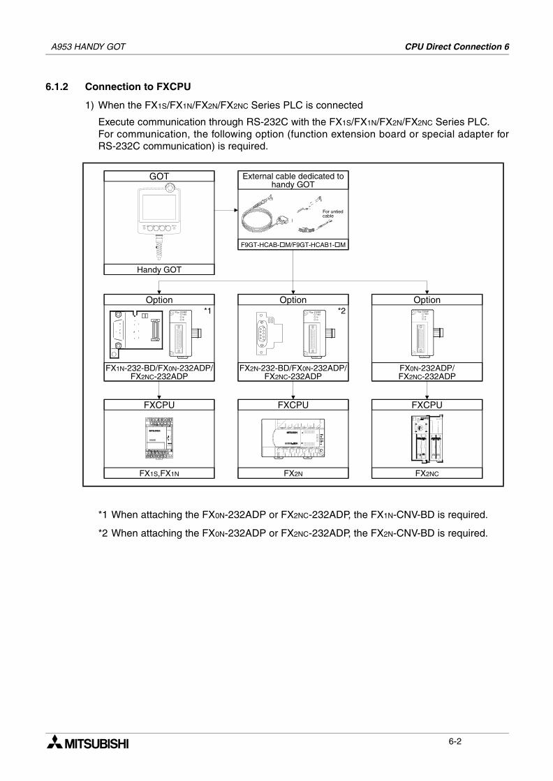
A953 HANDY GOT CPU Direct Connection 6
6.1.2 Connection to FXCPU
1) When the FX1S/FX1N/FX2N/FX2NC Series PLC is connected
Execute communication through RS-232C with the FX1S/FX1N/FX2N/FX2NC Series PLC.For communication, the following option (function extension board or special adapter forRS-232C communication) is required.
*1 When attaching the FX0N-232ADP or FX2NC-232ADP, the FX1N-CNV-BD is required.
*2 When attaching the FX0N-232ADP or FX2NC-232ADP, the FX2N-CNV-BD is required.
Option
FX1N-232-BD/FX0N-232ADP/FX2NC-232ADP
FXCPU
FX1S,FX1N
FXCPU
FX2NC
FXCPU
FX2N
GOT
Handy GOT
Option
FX2N-232-BD/FX0N-232ADP/FX2NC-232ADP
Option
FX0N-232ADP/FX2NC-232ADP
*1 *2
F9GT-HCAB- M/F9GT-HCAB1- M
For untiedcable
External cable dedicated tohandy GOT
6-2
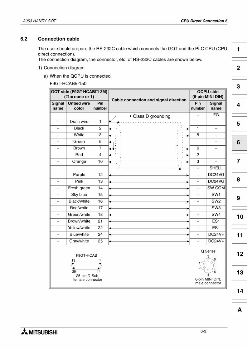
A953 HANDY GOT CPU Direct Connection 6
1
2
3
4
5
6
7
8
9
10
11
12
13
14
A
6.2 Connection cable
The user should prepare the RS-232C cable which connects the GOT and the PLC CPU (CPUdirect connection).The connection diagram, the connector, etc. of RS-232C cables are shown below.
1) Connection diagram
a) When the QCPU is connected
F9GT-HCAB5-150
GOT side (F9GT-HCAB -3M)( = none or 1)
Cable connection and signal direction
QCPU side(6-pin MINI DIN)
Signalname
Untied wire color
Pinnumber
Pinnumber
Signalname
− FG
− Drain wire 1
− Black 2 1 −− White 3 5 −− Green 5 −− Brown 7 6 −− Red 4 2 −− Orange 10 3 −
− SHELL
− Purple 12 − DC24VG
− Pink 13 − DC24VG
− Fresh green 14 − SW COM
− Sky blue 15 − SW1
− Black/white 16 − SW2
− Red/white 17 − SW3
− Green/white 18 − SW4
− Brown/white 21 − ES1
− Yellow/white 22 − ES1
− Blue/white 24 − DC24V+
− Gray/white 25 − DC24V+
Class D grounding
F9GT-HCAB
25-pin D-Sub,female connector
13 1
25 14
6-pin MINI DIN,male connector
Q Series
4
12
35
6
6-3
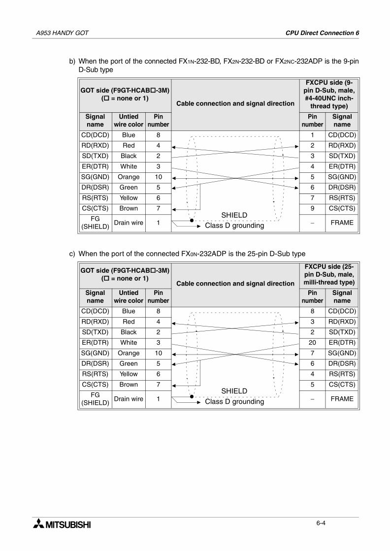
A953 HANDY GOT CPU Direct Connection 6
b) When the port of the connected FX1N-232-BD, FX2N-232-BD or FX2NC-232ADP is the 9-pinD-Sub type
c) When the port of the connected FX0N-232ADP is the 25-pin D-Sub type
GOT side (F9GT-HCAB -3M)( = none or 1)
Cable connection and signal direction
FXCPU side (9-pin D-Sub, male, #4-40UNC inch-
thread type)
Signalname
Untied wire color
Pinnumber
Pinnumber
Signalname
CD(DCD) Blue 8 1 CD(DCD)
RD(RXD) Red 4 2 RD(RXD)
SD(TXD) Black 2 3 SD(TXD)
ER(DTR) White 3 4 ER(DTR)
SG(GND) Orange 10 5 SG(GND)
DR(DSR) Green 5 6 DR(DSR)
RS(RTS) Yellow 6 7 RS(RTS)
CS(CTS) Brown 7 9 CS(CTS)
FG(SHIELD)
Drain wire 1 − FRAME
GOT side (F9GT-HCAB -3M)( = none or 1)
Cable connection and signal direction
FXCPU side (25-pin D-Sub, male, milli-thread type)
Signalname
Untied wire color
Pinnumber
Pinnumber
Signalname
CD(DCD) Blue 8 8 CD(DCD)
RD(RXD) Red 4 3 RD(RXD)
SD(TXD) Black 2 2 SD(TXD)
ER(DTR) White 3 20 ER(DTR)
SG(GND) Orange 10 7 SG(GND)
DR(DSR) Green 5 6 DR(DSR)
RS(RTS) Yellow 6 4 RS(RTS)
CS(CTS) Brown 7 5 CS(CTS)
FG(SHIELD)
Drain wire 1 − FRAME
SHIELDClass D grounding
SHIELD
Class D grounding
6-4
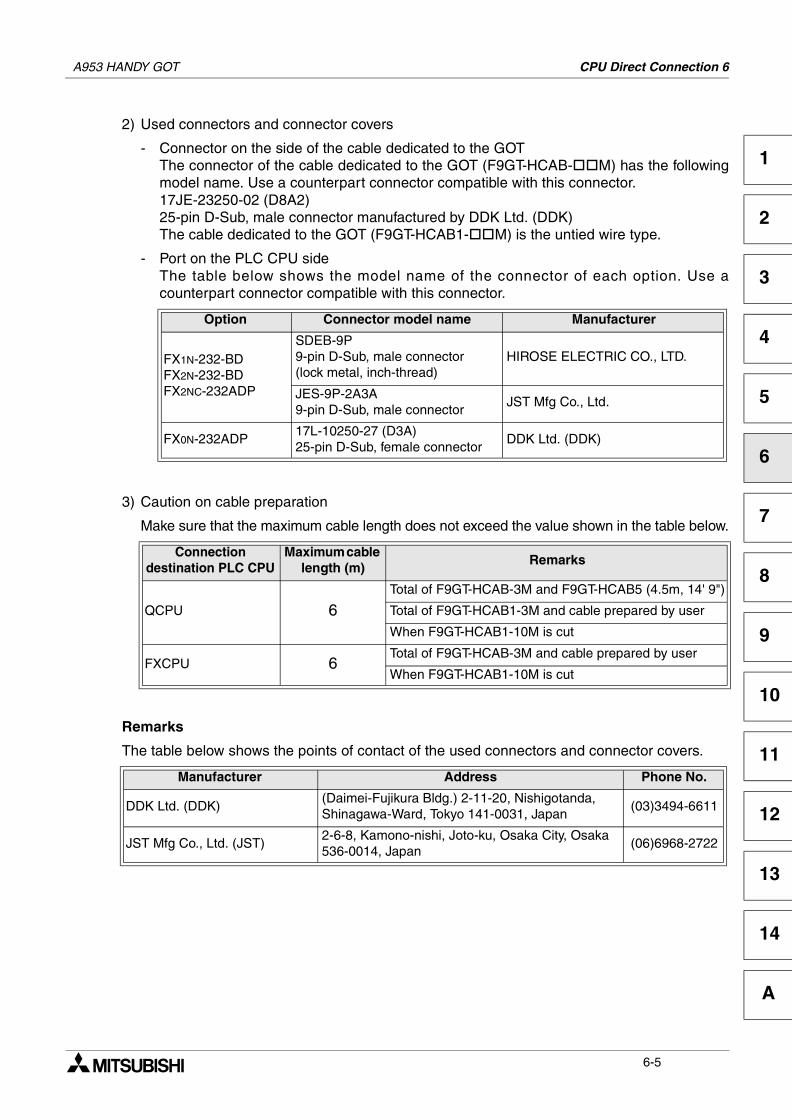
A953 HANDY GOT CPU Direct Connection 6
1
2
3
4
5
6
7
8
9
10
11
12
13
14
A
2) Used connectors and connector covers
- Connector on the side of the cable dedicated to the GOTThe connector of the cable dedicated to the GOT (F9GT-HCAB- M) has the followingmodel name. Use a counterpart connector compatible with this connector.17JE-23250-02 (D8A2)25-pin D-Sub, male connector manufactured by DDK Ltd. (DDK)The cable dedicated to the GOT (F9GT-HCAB1- M) is the untied wire type.
- Port on the PLC CPU sideThe table below shows the model name of the connector of each option. Use acounterpart connector compatible with this connector.
3) Caution on cable preparation
Make sure that the maximum cable length does not exceed the value shown in the table below.
Remarks
The table below shows the points of contact of the used connectors and connector covers.
Option Connector model name Manufacturer
FX1N-232-BDFX2N-232-BDFX2NC-232ADP
SDEB-9P 9-pin D-Sub, male connector(lock metal, inch-thread)
HIROSE ELECTRIC CO., LTD.
JES-9P-2A3A9-pin D-Sub, male connector
JST Mfg Co., Ltd.
FX0N-232ADP17L-10250-27 (D3A)25-pin D-Sub, female connector
DDK Ltd. (DDK)
Connection destination PLC CPU
Maximum cable length (m)
Remarks
QCPU 6Total of F9GT-HCAB-3M and F9GT-HCAB5 (4.5m, 14' 9")
Total of F9GT-HCAB1-3M and cable prepared by user
When F9GT-HCAB1-10M is cut
FXCPU 6Total of F9GT-HCAB-3M and cable prepared by user
When F9GT-HCAB1-10M is cut
Manufacturer Address Phone No.
DDK Ltd. (DDK)(Daimei-Fujikura Bldg.) 2-11-20, Nishigotanda,Shinagawa-Ward, Tokyo 141-0031, Japan
(03)3494-6611
JST Mfg Co., Ltd. (JST)2-6-8, Kamono-nishi, Joto-ku, Osaka City, Osaka 536-0014, Japan
(06)6968-2722
6-5

A953 HANDY GOT CPU Direct Connection 6
MEMO
6-6
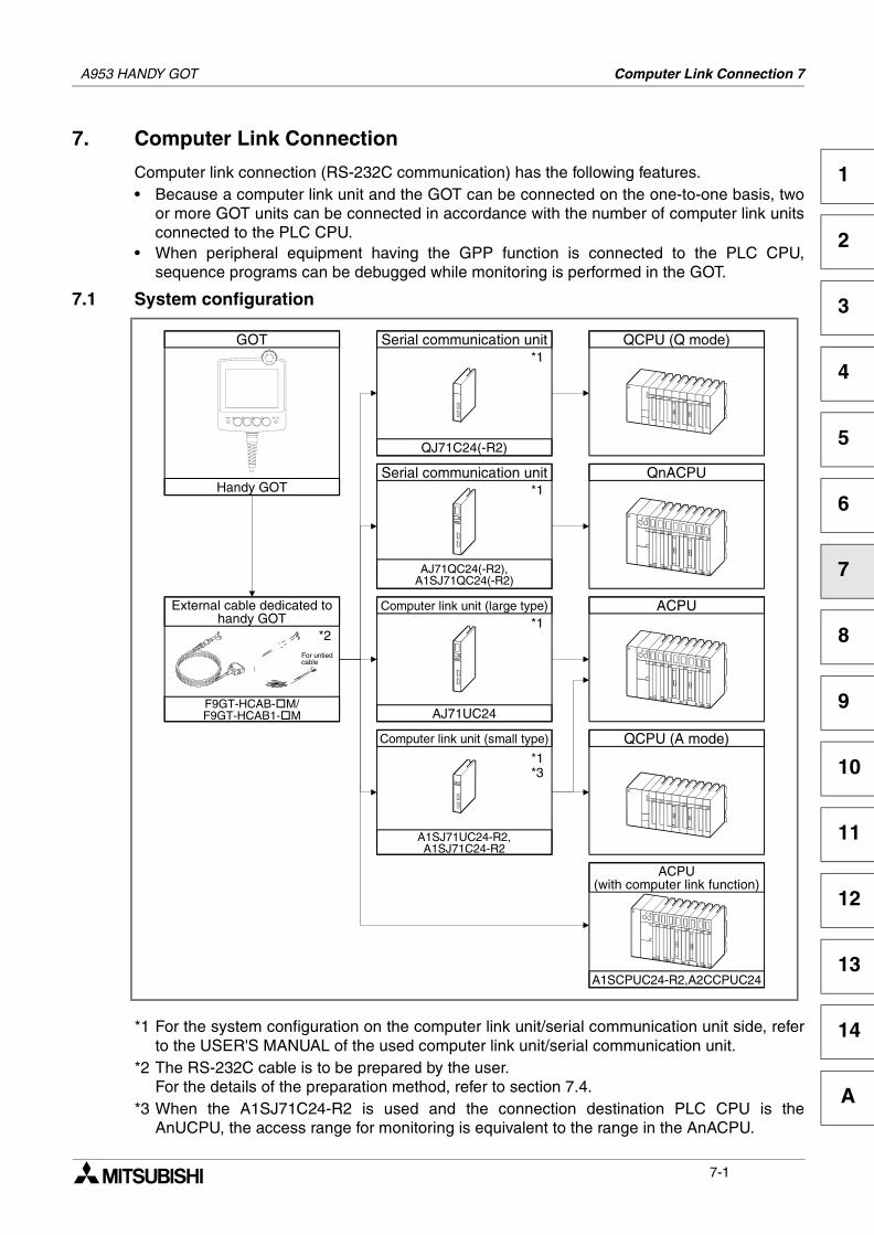
Computer Link Connection 7
1
2
3
4
5
6
7
8
9
10
11
12
13
14
A
7. Computer Link Connection
Computer link connection (RS-232C communication) has the following features.• Because a computer link unit and the GOT can be connected on the one-to-one basis, two
or more GOT units can be connected in accordance with the number of computer link unitsconnected to the PLC CPU.
• When peripheral equipment having the GPP function is connected to the PLC CPU,sequence programs can be debugged while monitoring is performed in the GOT.
7.1 System configuration
*1 For the system configuration on the computer link unit/serial communication unit side, referto the USER'S MANUAL of the used computer link unit/serial communication unit.
*2 The RS-232C cable is to be prepared by the user.For the details of the preparation method, refer to section 7.4.
*3 When the A1SJ71C24-R2 is used and the connection destination PLC CPU is theAnUCPU, the access range for monitoring is equivalent to the range in the AnACPU.
GOT
Handy GOT
QCPU (Q mode)Serial communication unit
QJ71C24(-R2)
QnACPUSerial communication unit
AJ71QC24(-R2),A1SJ71QC24(-R2)
ACPUComputer link unit (large type)
AJ71UC24
QCPU (A mode)Computer link unit (small type)
A1SJ71UC24-R2,A1SJ71C24-R2
ACPU(with computer link function)
A1SCPUC24-R2,A2CCPUC24
*1
*1
*1
*1*3
F9GT-HCAB- M/F9GT-HCAB1- M
*2For untiedcable
External cable dedicated tohandy GOT
A953 HANDY GOT
7-1
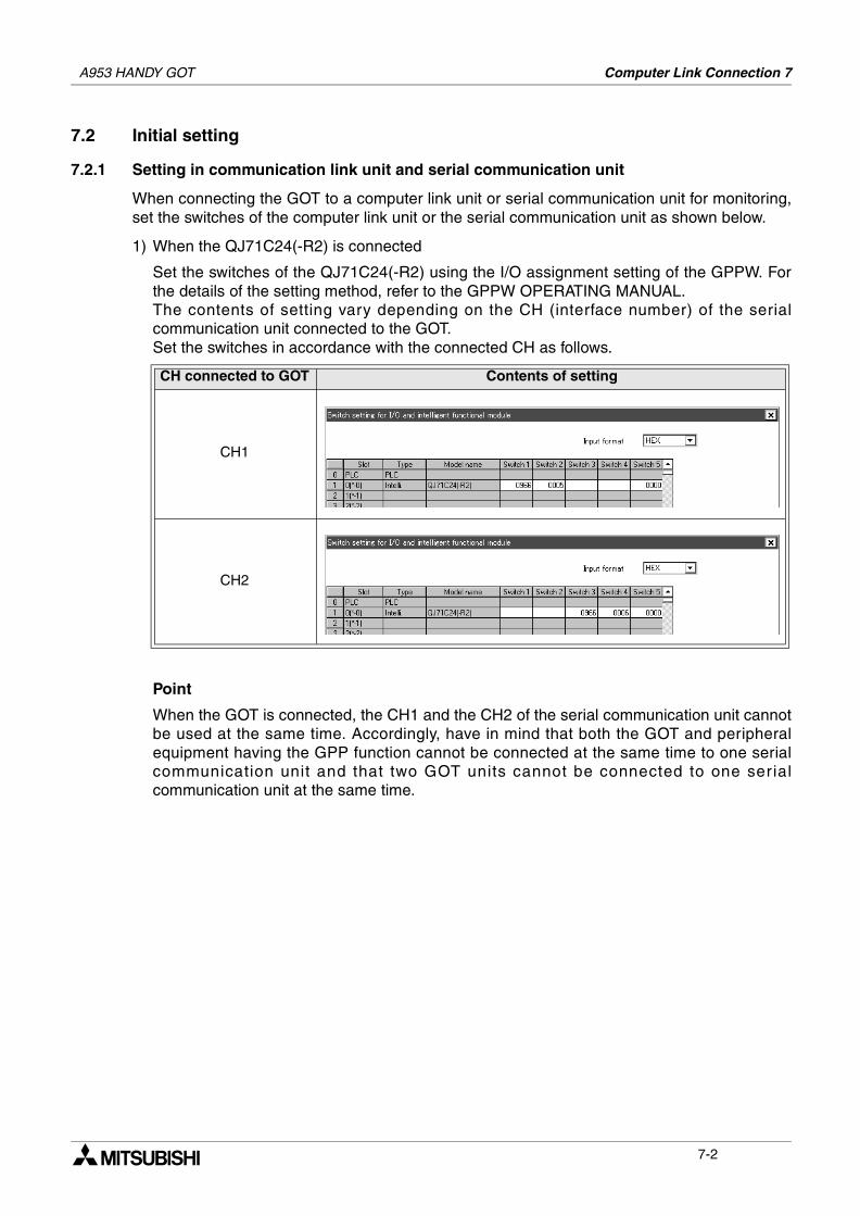
A953 HANDY GOT Computer Link Connection 7
7.2 Initial setting
7.2.1 Setting in communication link unit and serial communication unit
When connecting the GOT to a computer link unit or serial communication unit for monitoring,set the switches of the computer link unit or the serial communication unit as shown below.
1) When the QJ71C24(-R2) is connected
Set the switches of the QJ71C24(-R2) using the I/O assignment setting of the GPPW. Forthe details of the setting method, refer to the GPPW OPERATING MANUAL.The contents of setting vary depending on the CH (interface number) of the serialcommunication unit connected to the GOT.Set the switches in accordance with the connected CH as follows.
Point
When the GOT is connected, the CH1 and the CH2 of the serial communication unit cannotbe used at the same time. Accordingly, have in mind that both the GOT and peripheralequipment having the GPP function cannot be connected at the same time to one serialcommunication unit and that two GOT units cannot be connected to one serialcommunication unit at the same time.
CH connected to GOT Contents of setting
CH1
CH2
7-2
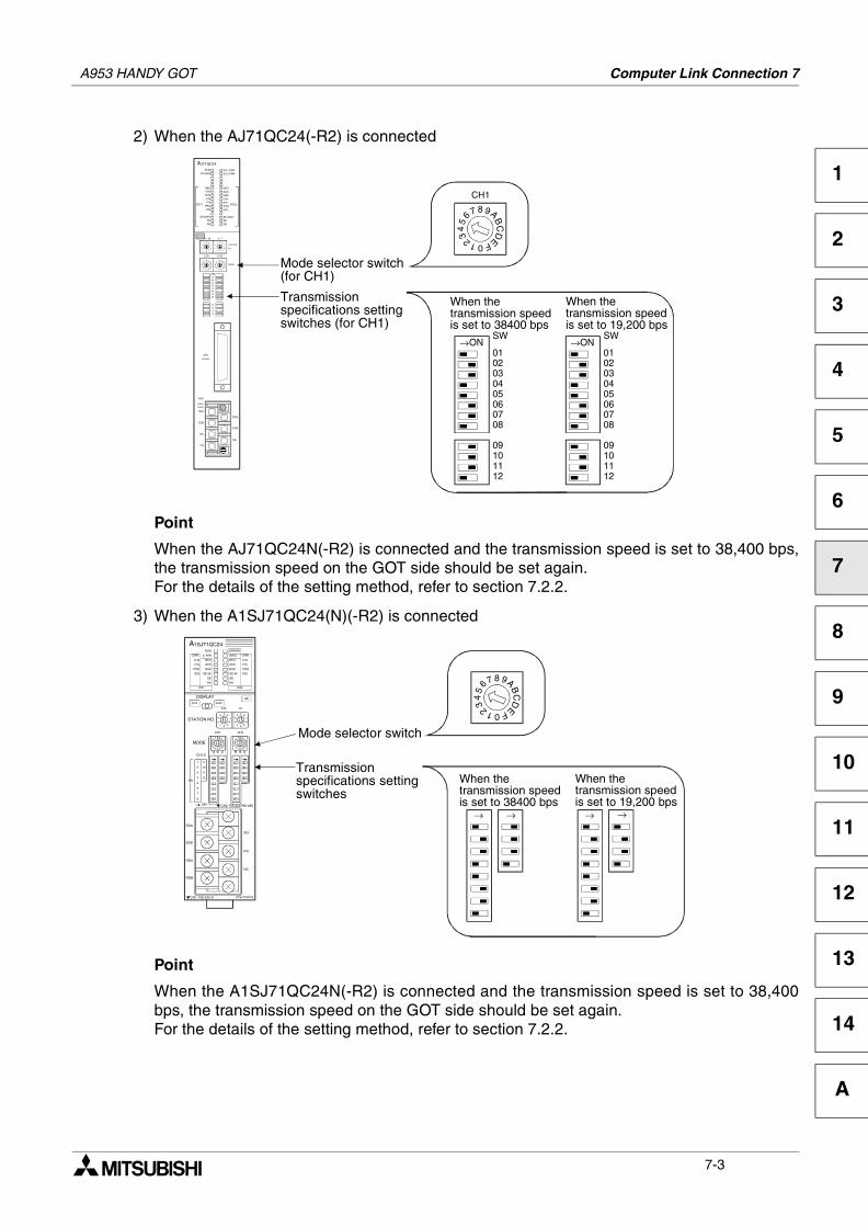
A953 HANDY GOT Computer Link Connection 7
1
2
3
4
5
6
7
8
9
10
11
12
13
14
A
2) When the AJ71QC24(-R2) is connected
Point
When the AJ71QC24N(-R2) is connected and the transmission speed is set to 38,400 bps,the transmission speed on the GOT side should be set again.For the details of the setting method, refer to section 7.2.2.
3) When the A1SJ71QC24(N)(-R2) is connected
Point
When the A1SJ71QC24N(-R2) is connected and the transmission speed is set to 38,400bps, the transmission speed on the GOT side should be set again.For the details of the setting method, refer to section 7.2.2.
AJ71QC24
RUN
CPUR/W
NEUACK
NAK
C/NP/S
PROSIO
SD.WAITSD
RD
CH1.ERR.
CH2.ERR.
NEU
ACKNAK
C/N
P/SPRO
SIO
SD.WAITSD
RD
CH.1 CH.2
•~1
CH1 CH2
STATION
No.
MODE
SW01
02
03
04
05
06
07
08
09
10
11
12
RDA
RDB
SG
SDA
SDB
NC
FG
CH1
RS-232C
CH2
RS422
RS485
876
54
3
2 1 0 F
E
DC
BA9 876
54
3
2 1 0 F
E
DC
BA9
54
32
1 0 9
87
6 54
32
1 0 9
87
6
•~10
Mode selector switch(for CH1)
Transmissionspecifications settingswitches (for CH1)
876
54
3 2 1 0FE
DC
BA9
CH1
→ON
02030405060708
01
SW
09101112
→ON
02030405060708
01
SW
09101112
When thetransmission speedis set to 38400 bps
When thetransmission speedis set to 19,200 bps
A1SJ71QC24
CH1 CH2
ERROR
RD
SW.E
NEU
ACK
NAK
SD.W.
SD
STS ERR.
DISPLAY
54
32
1 0 9
87
6 54
32
1 0 9
87
6
1
8
2
3
4
5
6
7
9
10
11
12SW
CH1/
87654
3 2 10FE
DC
BA9
CH1 CH2
X10 X1
STATION NO.
MODE
A1SJ71QC24
RUN
RD
C.R/W
NEU
ACK
NAK
SD.W.
SD
ERR.
C/N
P/S
PRO
SIO
2
ERR.
C/N
P/S
PRO
SIO
AB
CH2 RS-422/RS-485
CH1 RS-232-C
SG
FG
NC
RDA
RDB
87654
3 2 10FE
DC
BA9
ON
Mode selector switch
Transmissionspecifications settingswitches
876
54
3 2 1 0FE
DC
BA9
SDA
SDB
When thetransmission speedis set to 38400 bps
When thetransmission speedis set to 19,200 bps
→ → → →
7-3
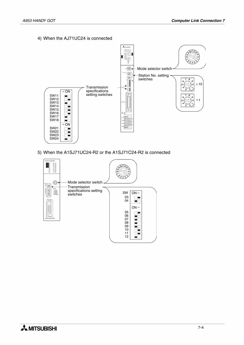
A953 HANDY GOT Computer Link Connection 7
4) When the AJ71UC24 is connected
5) When the A1SJ71UC24-R2 or the A1SJ71C24-R2 is connected
AJ71UC24
2 - C / N2 - P / S2 - PRO
2 - SIO4 - C / N4 - P / S4 - PRO4 - SIO
CPUR / W
COMM . D . MM . D . LB0B1B2
L 4L 5L 6
RUN2 - SD2 - RD
2 - NEU2 - ACK2 - NAK4 - NEU
4 - ACK4 - NAK
4 - SD4 - RD
L 1
L 2L 3
MODE
STATION NO.
*~ 10
*~ 1
SW1112131415161718
2122
2324
O N
RS - 422RS - 485
SDA
SDB
RDA
RDB
SG
FG
NC
RS-232-C
CBA
98
7 6 5 432
10
FED
Transmissionspecificationssetting switches
ONSW11SW12SW13SW14SW15SW16SW17SW18
SW21SW22SW23SW24
ON
2
10
9876
54 3
× 10
2
10
9876
54 3
1
Station No. settingswitches
Mode selector switch
→
×
→
Mode selector switchTransmissionspecifications settingswitches ON
0304
0506070809101112
A1SJ71UC24-R2
NEU
ACKNAK
C/N
NEU
ACK
NAK
C/N
P/S
PRO
SIO
SIO
SW0304
0506070809101112
RS-232-C
A1SJ71UC24-R2
MODE
1.FORM12.FORM23.FORM34.FORM45.MOFORM
CBA
98
7 6 5 432
10
FED
ON
SW ←
←
7-4
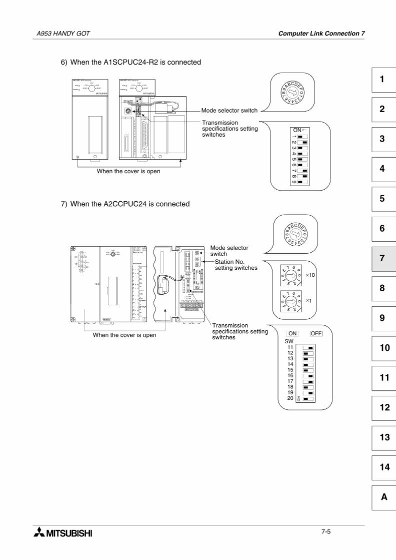
A953 HANDY GOT Computer Link Connection 7
1
2
3
4
5
6
7
8
9
10
11
12
13
14
A
6) When the A1SCPUC24-R2 is connected
7) When the A2CCPUC24 is connected
Mode selector switch
Transmissionspecifications settingswitches
CBA
98
7 6 5 4321
0FED
ON
12
34
56
78
9
PULL
MELSEC A1S CPU24-R2
STOP
RUN
RESETRESET
L CLRRUN
ERROR
STOP
RUN
RESETRESET
L CLRRUN
ERROR
MELSEC A1S CPU24-R2
MITSUBISHIMITSUBISHI
When the cover is open
←
Mode selectorswitch
Transmissionspecifications settingswitches
CBA
98
7 6 5 432
10
FED
When the cover is open
ON
SW11121314151617181920
ON OFF
2
10
9876
54 3
10
2
10
9876
54 3
1
Station No.setting switches
×
×
7-5
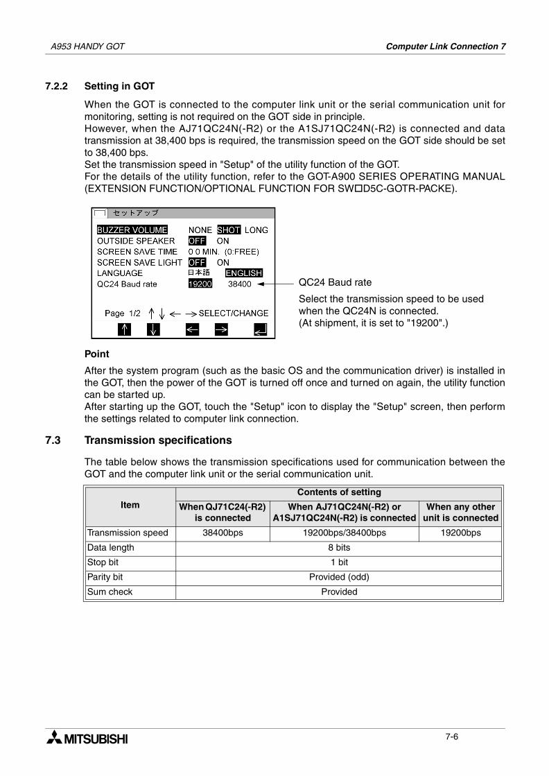
A953 HANDY GOT Computer Link Connection 7
7.2.2 Setting in GOT
When the GOT is connected to the computer link unit or the serial communication unit formonitoring, setting is not required on the GOT side in principle.However, when the AJ71QC24N(-R2) or the A1SJ71QC24N(-R2) is connected and datatransmission at 38,400 bps is required, the transmission speed on the GOT side should be setto 38,400 bps.Set the transmission speed in "Setup" of the utility function of the GOT.For the details of the utility function, refer to the GOT-A900 SERIES OPERATING MANUAL(EXTENSION FUNCTION/OPTIONAL FUNCTION FOR SW D5C-GOTR-PACKE).
Point
After the system program (such as the basic OS and the communication driver) is installed inthe GOT, then the power of the GOT is turned off once and turned on again, the utility functioncan be started up.After starting up the GOT, touch the "Setup" icon to display the "Setup" screen, then performthe settings related to computer link connection.
7.3 Transmission specifications
The table below shows the transmission specifications used for communication between theGOT and the computer link unit or the serial communication unit.
ItemContents of setting
When QJ71C24(-R2) is connected
When AJ71QC24N(-R2) or A1SJ71QC24N(-R2) is connected
When any other unit is connected
Transmission speed 38400bps 19200bps/38400bps 19200bps
Data length 8 bits
Stop bit 1 bit
Parity bit Provided (odd)
Sum check Provided
QC24 Baud rate
Select the transmission speed to be used when the QC24N is connected.(At shipment, it is set to "19200".)
7-6
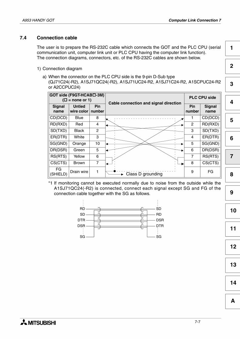
A953 HANDY GOT Computer Link Connection 7
1
2
3
4
5
6
7
8
9
10
11
12
13
14
A
7.4 Connection cable
The user is to prepare the RS-232C cable which connects the GOT and the PLC CPU (serialcommunication unit, computer link unit or PLC CPU having the computer link function).The connection diagrams, connectors, etc. of the RS-232C cables are shown below.
1) Connection diagram
a) When the connector on the PLC CPU side is the 9-pin D-Sub type(QJ71C24(-R2), A1SJ71QC24(-R2), A1SJ71UC24-R2, A1SJ71C24-R2, A1SCPUC24-R2or A2CCPUC24)
*1 If monitoring cannot be executed normally due to noise from the outside while theA1SJ71QC24(-R2) is connected, connect each signal except SG and FG of theconnection cable together with the SG as follows.
GOT side (F9GT-HCAB -3M)( = none or 1)
Cable connection and signal directionPLC CPU side
Signalname
Untied wire color
Pinnumber
Pinnumber
Signalname
CD(DCD) Blue 8 1 CD(DCD)
RD(RXD) Red 4 2 RD(RXD)
SD(TXD) Black 2 3 SD(TXD)
ER(DTR) White 3 4 ER(DTR)
SG(GND) Orange 10 5 SG(GND)
DR(DSR) Green 5 6 DR(DSR)
RS(RTS) Yellow 6 7 RS(RTS)
CS(CTS) Brown 7 8 CS(CTS)
FG(SHIELD)
Drain wire 1 9 FGClass D grounding
RD
SD
DTR
DSR
SG
SD
RD
DSR
DTR
SG
7-7
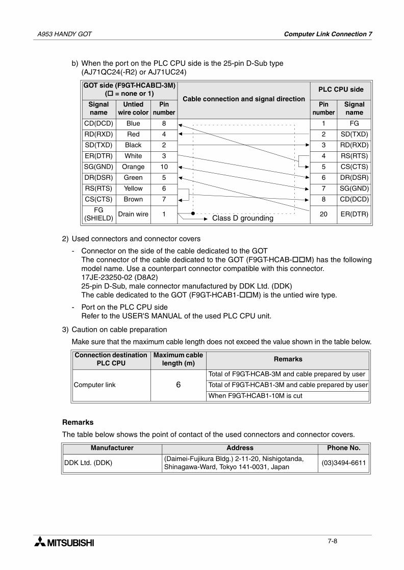
A953 HANDY GOT Computer Link Connection 7
b) When the port on the PLC CPU side is the 25-pin D-Sub type(AJ71QC24(-R2) or AJ71UC24)
2) Used connectors and connector covers
- Connector on the side of the cable dedicated to the GOTThe connector of the cable dedicated to the GOT (F9GT-HCAB- M) has the followingmodel name. Use a counterpart connector compatible with this connector.17JE-23250-02 (D8A2)25-pin D-Sub, male connector manufactured by DDK Ltd. (DDK)The cable dedicated to the GOT (F9GT-HCAB1- M) is the untied wire type.
- Port on the PLC CPU sideRefer to the USER'S MANUAL of the used PLC CPU unit.
3) Caution on cable preparation
Make sure that the maximum cable length does not exceed the value shown in the table below.
Remarks
The table below shows the point of contact of the used connectors and connector covers.
GOT side (F9GT-HCAB -3M)( = none or 1)
Cable connection and signal directionPLC CPU side
Signalname
Untied wire color
Pinnumber
Pinnumber
Signalname
CD(DCD) Blue 8 1 FG
RD(RXD) Red 4 2 SD(TXD)
SD(TXD) Black 2 3 RD(RXD)
ER(DTR) White 3 4 RS(RTS)
SG(GND) Orange 10 5 CS(CTS)
DR(DSR) Green 5 6 DR(DSR)
RS(RTS) Yellow 6 7 SG(GND)
CS(CTS) Brown 7 8 CD(DCD)
FG(SHIELD)
Drain wire 1 20 ER(DTR)
Connection destination PLC CPU
Maximum cable length (m)
Remarks
Computer link 6Total of F9GT-HCAB-3M and cable prepared by user
Total of F9GT-HCAB1-3M and cable prepared by user
When F9GT-HCAB1-10M is cut
Manufacturer Address Phone No.
DDK Ltd. (DDK)(Daimei-Fujikura Bldg.) 2-11-20, Nishigotanda,Shinagawa-Ward, Tokyo 141-0031, Japan
(03)3494-6611
Class D grounding
7-8
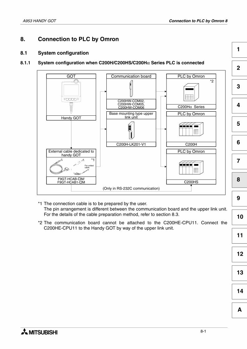
Connection to PLC by Omron 8
1
2
3
4
5
6
7
8
9
10
11
12
13
14
A
8. Connection to PLC by Omron
8.1 System configuration
8.1.1 System configuration when C200H/C200HS/C200Hα Series PLC is connected
*1 The connection cable is to be prepared by the user.The pin arrangement is different between the communication board and the upper link unit.For the details of the cable preparation method, refer to section 8.3.
*2 The communication board cannot be attached to the C200HE-CPU11. Connect theC200HE-CPU11 to the Handy GOT by way of the upper link unit.
GOT
Handy GOT
PLC by Omron
C200Hα Series
Communication board
C200HW-COM02,C200HW-COM05,C200HW-COM06
Base mounting type upperlink unit
C200H-LK201-V1
*2
PLC by Omron
C200H
PLC by Omron
C200HS
(Only in RS-232C communication)
F9GT-HCAB- M/F9GT-HCAB1- M
*1For untiedcable
External cable dedicated tohandy GOT
A953 HANDY GOT
8-1
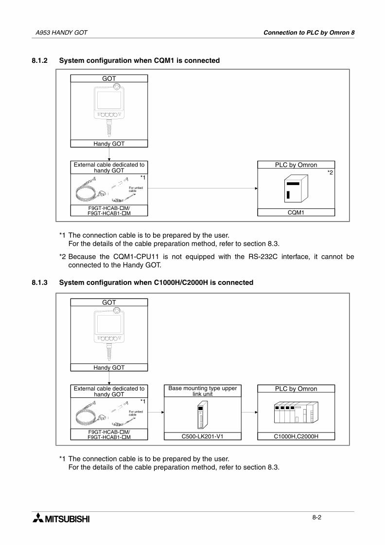
A953 HANDY GOT Connection to PLC by Omron 8
8.1.2 System configuration when CQM1 is connected
*1 The connection cable is to be prepared by the user.For the details of the cable preparation method, refer to section 8.3.
*2 Because the CQM1-CPU11 is not equipped with the RS-232C interface, it cannot beconnected to the Handy GOT.
8.1.3 System configuration when C1000H/C2000H is connected
*1 The connection cable is to be prepared by the user.For the details of the cable preparation method, refer to section 8.3.
GOT
Handy GOT
PLC by Omron
CQM1
*2
F9GT-HCAB- M/F9GT-HCAB1- M
*1
For untiedcable
External cable dedicated tohandy GOT
GOT
Handy GOT
C500-LK201-V1
PLC by Omron
C1000H,C2000H
*1
Base mounting type upperlink unit
F9GT-HCAB- M/F9GT-HCAB1- M
For untiedcable
External cable dedicated tohandy GOT
8-2
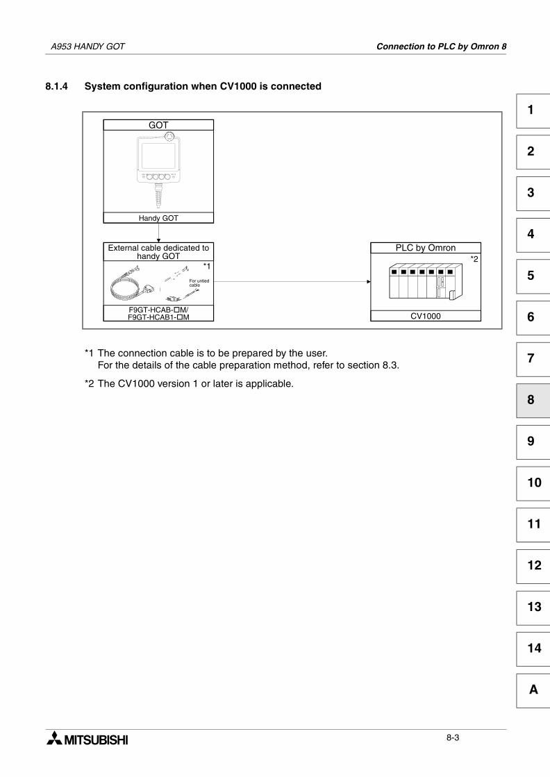
A953 HANDY GOT Connection to PLC by Omron 8
1
2
3
4
5
6
7
8
9
10
11
12
13
14
A
8.1.4 System configuration when CV1000 is connected
*1 The connection cable is to be prepared by the user.For the details of the cable preparation method, refer to section 8.3.
*2 The CV1000 version 1 or later is applicable.
GOT
Handy GOT
PLC by Omron
CV1000
*2
F9GT-HCAB- M/F9GT-HCAB1- M
*1
For untiedcable
External cable dedicated tohandy GOT
8-3
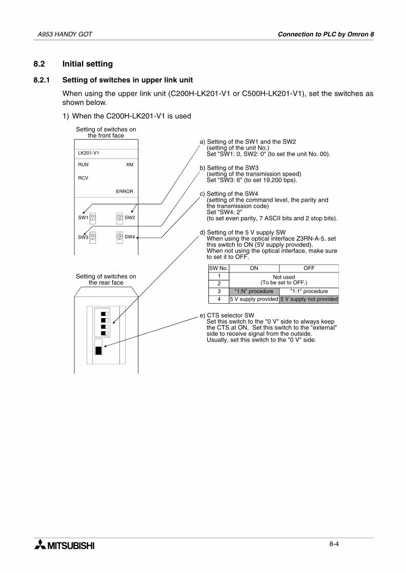
A953 HANDY GOT Connection to PLC by Omron 8
8.2 Initial setting
8.2.1 Setting of switches in upper link unit
When using the upper link unit (C200H-LK201-V1 or C500H-LK201-V1), set the switches asshown below.
1) When the C200H-LK201-V1 is used
LK201-V1
RUN
RCV
XM
ERROR
SW1 SW2
SW3 SW4
Setting of switches onthe front face
Setting of switches onthe rear face
a) Setting of the SW1 and the SW2 (setting of the unit No.) Set "SW1: 0, SW2: 0" (to set the unit No. 00).
b) Setting of the SW3 (setting of the transmission speed) Set "SW3: 6" (to set 19,200 bps).
c) Setting of the SW4 (setting of the command level, the parity and the transmission code) Set "SW4: 2" (to set even parity, 7 ASCII bits and 2 stop bits).
d) Setting of the 5 V supply SW When using the optical interface Z3RN-A-5, set this switch to ON (5V supply provided). When not using the optical interface, make sure to set it to OFF.
SW No. ON OFF1234
Not used(To be set to OFF.)
"1:N" procedure "1:1" procedure5 V supply provided 5 V supply not provided
e) CTS selector SW Set this switch to the "0 V" side to always keep the CTS at ON. Set this switch to the "external" side to receive signal from the outside. Usually, set this switch to the "0 V" side.
8-4
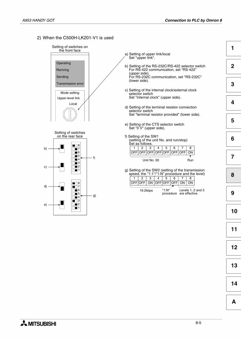
A953 HANDY GOT Connection to PLC by Omron 8
1
2
3
4
5
6
7
8
9
10
11
12
13
14
A
2) When the C500H-LK201-V1 is used
a) Setting of upper link/local Set "upper link".
b) Setting of the RS-232C/RS-422 selector switch For RS-422 communication, set "RS-422" (upper side). For RS-232C communication, set "RS-232C" (lower side).
c) Setting of the internal clock/external clock selector switch Set "internal clock" (upper side).
d) Setting of the terminal resistor connection selector switch Set "terminal resistor provided" (lower side).
1OFF
f) Setting of the SW1 (setting of the unit No. and run/stop) Set as follows.8
1
765432
8
1
765432
Operating
Reciving
Sending
Transmission error
Mode setting
Upper-level link
Local
Setting of switcheson the rear face
b)
c)
d)
e)
f)
g)
e) Setting of the CTS selector switch Set "0 V" (upper side).
2 3 4 5 6 7 8OFF OFF OFF OFF OFF OFF ON
Unit No. 00
"1:N"procedure
1OFF
g) Setting of the SW2 (setting of the transmission speed, the "1:1"/"1:N" procedure and the level)
2 3 4 5 6 7 8OFF ON OFF OFF OFF ON ON
19.2kbps
Run
Levels 1, 2 and 3are effective.
Setting of switches onthe front face
8-5
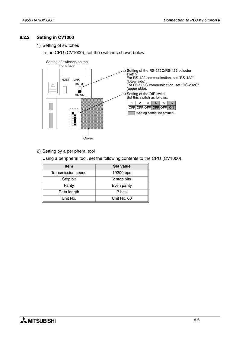
A953 HANDY GOT Connection to PLC by Omron 8
8.2.2 Setting in CV1000
1) Setting of switches
In the CPU (CV1000), set the switches shown below.
2) Setting by a peripheral tool
Using a peripheral tool, set the following contents to the CPU (CV1000).
Item Set value
Transmission speed 19200 bps
Stop bit 2 stop bits
Parity Even parity
Data length 7 bits
Unit No. Unit No. 00
HOST LINK
RS-232
RS-422
Setting of switches on thefront face‚Ì
Cover
a) Setting of the RS-232C/RS-422 selector switch For RS-422 communication, set "RS-422" (lower side). For RS-232C communication, set "RS-232C" (upper side).
b) Setting of the DIP switch Set this switch as follows.
1OFF
2 3 4 5 6OFF OFF OFF OFF ON
:Setting cannot be omitted.
8-6
A953 HANDY GOT Connection to PLC by Omron 8
1
2
3
4
5
6
7
8
9
10
11
12
13
14
A
8.2.3 Initialization of CQM1
When using the RS-232C port of the CQM1, write numeric values to the devices shown below,and initialize the RS-232C port of the CQM1 using a peripheral tool or the DM monitor.For the details, refer to the CQM1 INSTRUCTION MANUAL.
8.2.4 Communication board initialization program
When using a communication board, write numeric values to the devices shown below, andinitialize the port A of the communication board.For the use of each device and the initialization program, refer to the INSTRUCTION MANUALof the used communication board.
Device name Written value Device name Written value
DM6645 0001H DM6646 0304H
DM6647 0000H DM6648 0000H
DM6649 0000H −
Device name Written value Device name Written value
DM6550~DM6654 − DM6555 0001H
DM6556 0304H DM6557 0000H
DM6558 0000H DM6559 0000H
8-7
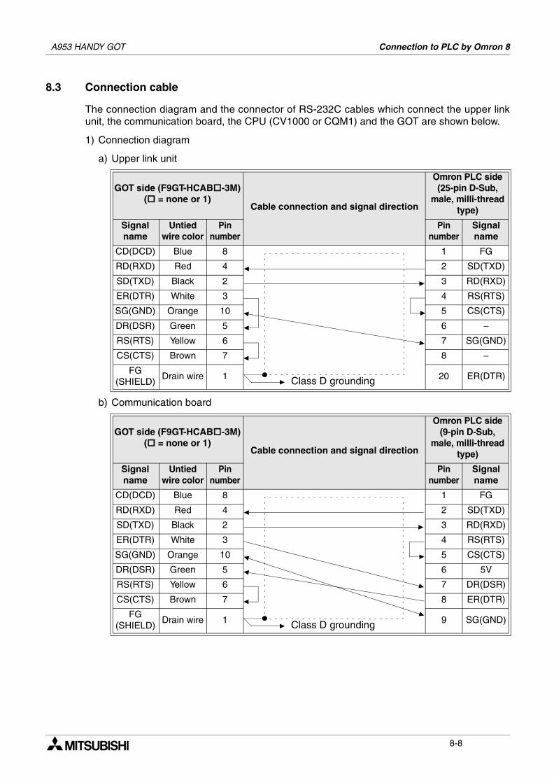
A953 HANDY GOT Connection to PLC by Omron 8
8.3 Connection cable
The connection diagram and the connector of RS-232C cables which connect the upper linkunit, the communication board, the CPU (CV1000 or CQM1) and the GOT are shown below.
1) Connection diagram
a) Upper link unit
b) Communication board
GOT side (F9GT-HCAB -3M)( = none or 1)
Cable connection and signal direction
Omron PLC side(25-pin D-Sub,
male, milli-thread type)
Signalname
Untied wire color
Pinnumber
Pinnumber
Signalname
CD(DCD) Blue 8 1 FG
RD(RXD) Red 4 2 SD(TXD)
SD(TXD) Black 2 3 RD(RXD)
ER(DTR) White 3 4 RS(RTS)
SG(GND) Orange 10 5 CS(CTS)
DR(DSR) Green 5 6 −RS(RTS) Yellow 6 7 SG(GND)
CS(CTS) Brown 7 8 −FG
(SHIELD)Drain wire 1 20 ER(DTR)
GOT side (F9GT-HCAB -3M)( = none or 1)
Cable connection and signal direction
Omron PLC side(9-pin D-Sub,
male, milli-thread type)
Signalname
Untied wire color
Pinnumber
Pinnumber
Signalname
CD(DCD) Blue 8 1 FG
RD(RXD) Red 4 2 SD(TXD)
SD(TXD) Black 2 3 RD(RXD)
ER(DTR) White 3 4 RS(RTS)
SG(GND) Orange 10 5 CS(CTS)
DR(DSR) Green 5 6 5V
RS(RTS) Yellow 6 7 DR(DSR)
CS(CTS) Brown 7 8 ER(DTR)
FG(SHIELD)
Drain wire 1 9 SG(GND)
Class D grounding
Class D grounding
8-8
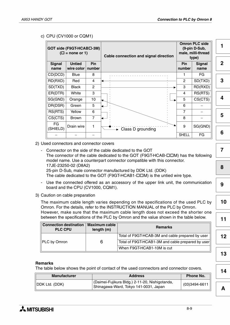
A953 HANDY GOT Connection to PLC by Omron 8
1
2
3
4
5
6
7
8
9
10
11
12
13
14
A
c) CPU (CV1000 or CQM1)
2) Used connectors and connector covers
- Connector on the side of the cable dedicated to the GOTThe connector of the cable dedicated to the GOT (F9GT-HCAB- M) has the followingmodel name. Use a counterpart connector compatible with this connector.17JE-23250-02 (D8A2)25-pin D-Sub, male connector manufactured by DDK Ltd. (DDK)The cable dedicated to the GOT (F9GT-HCAB1- M) is the untied wire type.
- Use the connected offered as an accessory of the upper link unit, the communicationboard and the CPU (CV1000, CQM1).
3) Caution on cable preparation
The maximum cable length varies depending on the specifications of the used PLC byOmron. For the details, refer to the INSTRUCTION MANUAL of the PLC by Omron.However, make sure that the maximum cable length does not exceed the shorter onebetween the specifications of the PLC by Omron and the value shown in the table below.
RemarksThe table below shows the point of contact of the used connectors and connector covers.
GOT side (F9GT-HCAB -3M)( = none or 1)
Cable connection and signal direction
Omron PLC side(9-pin D-Sub,
male, milli-thread type)
Signalname
Untied wire color
Pinnumber
Pinnumber
Signalname
CD(DCD) Blue 8 1 FG
RD(RXD) Red 4 2 SD(TXD)
SD(TXD) Black 2 3 RD(RXD)
ER(DTR) White 3 4 RS(RTS)
SG(GND) Orange 10 5 CS(CTS)
DR(DSR) Green 5 6 −RS(RTS) Yellow 6 7 −CS(CTS) Brown 7 8 −
FG(SHIELD)
Drain wire 1 9 SG(GND)
− − − SHELL FG
Connection destination PLC CPU
Maximum cable length (m)
Remarks
PLC by Omron 6Total of F9GT-HCAB-3M and cable prepared by user
Total of F9GT-HCAB1-3M and cable prepared by user
When F9GT-HCAB1-10M is cut
Manufacturer Address Phone No.
DDK Ltd. (DDK)(Daimei-Fujikura Bldg.) 2-11-20, Nishigotanda,Shinagawa-Ward, Tokyo 141-0031, Japan
(03)3494-6611
Class D grounding
8-9

A953 HANDY GOT Connection to PLC by Omron 8
MEMO
8-10
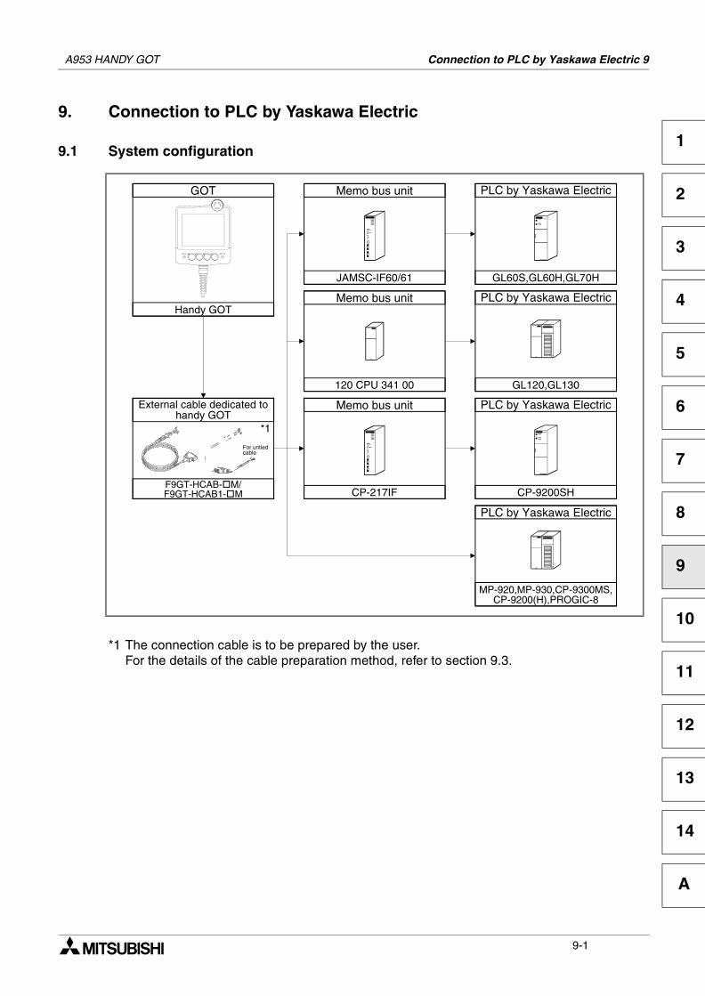
Connection to PLC by Yaskawa Electric 9
1
2
3
4
5
6
7
8
9
10
11
12
13
14
A
9. Connection to PLC by Yaskawa Electric
9.1 System configuration
*1 The connection cable is to be prepared by the user.For the details of the cable preparation method, refer to section 9.3.
GOT
Handy GOT
PLC by Yaskawa Electric
GL60S,GL60H,GL70H
Memo bus unit
JAMSC-IF60/61
Memo bus unit
120 CPU 341 00
PLC by Yaskawa Electric
GL120,GL130
PLC by Yaskawa Electric
CP-9200SH
Memo bus unit
CP-217IF
PLC by Yaskawa Electric
MP-920,MP-930,CP-9300MS,CP-9200(H),PROGIC-8
F9GT-HCAB- M/F9GT-HCAB1- M
*1
For untiedcable
External cable dedicated tohandy GOT
A953 HANDY GOT
9-1
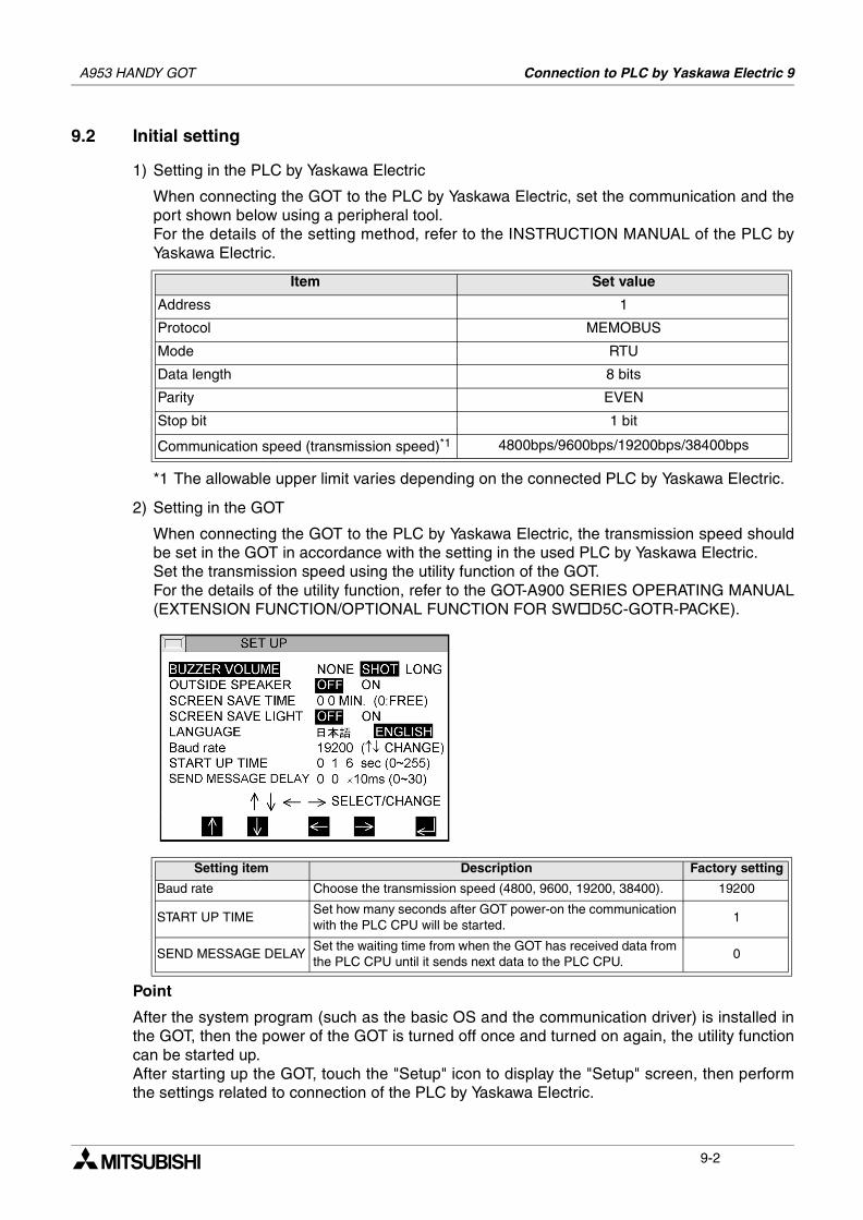
A953 HANDY GOT Connection to PLC by Yaskawa Electric 9
9.2 Initial setting
1) Setting in the PLC by Yaskawa Electric
When connecting the GOT to the PLC by Yaskawa Electric, set the communication and theport shown below using a peripheral tool.For the details of the setting method, refer to the INSTRUCTION MANUAL of the PLC byYaskawa Electric.
*1 The allowable upper limit varies depending on the connected PLC by Yaskawa Electric.
2) Setting in the GOT
When connecting the GOT to the PLC by Yaskawa Electric, the transmission speed shouldbe set in the GOT in accordance with the setting in the used PLC by Yaskawa Electric.Set the transmission speed using the utility function of the GOT.For the details of the utility function, refer to the GOT-A900 SERIES OPERATING MANUAL(EXTENSION FUNCTION/OPTIONAL FUNCTION FOR SW D5C-GOTR-PACKE).
Point
After the system program (such as the basic OS and the communication driver) is installed inthe GOT, then the power of the GOT is turned off once and turned on again, the utility functioncan be started up.After starting up the GOT, touch the "Setup" icon to display the "Setup" screen, then performthe settings related to connection of the PLC by Yaskawa Electric.
Item Set value
Address 1
Protocol MEMOBUS
Mode RTU
Data length 8 bits
Parity EVEN
Stop bit 1 bit
Communication speed (transmission speed)*1 4800bps/9600bps/19200bps/38400bps
Setting item Description Factory setting
Baud rate Choose the transmission speed (4800, 9600, 19200, 38400). 19200
START UP TIMESet how many seconds after GOT power-on the communication with the PLC CPU will be started.
1
SEND MESSAGE DELAYSet the waiting time from when the GOT has received data from the PLC CPU until it sends next data to the PLC CPU.
0
9-2
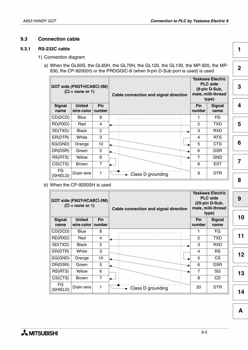
A953 HANDY GOT Connection to PLC by Yaskawa Electric 9
1
2
3
4
5
6
7
8
9
10
11
12
13
14
A
9.3 Connection cable
9.3.1 RS-232C cable
1) Connection diagram
a) When the GL60S, the GL60H, the GL70H, the GL120, the GL130, the MP-920, the MP-930, the CP-9200(H) or the PROGGIC-8 (when 9-pin D-Sub port is used) is used
b) When the CP-9200SH is used
GOT side (F9GT-HCAB -3M)( = none or 1)
Cable connection and signal direction
Yaskawa Electric PLC side
(9-pin D-Sub, male, milli-thread
type)
Signalname
Untied wire color
Pinnumber
Pinnumber
Signalname
CD(DCD) Blue 8 1 FG
RD(RXD) Red 4 2 TXD
SD(TXD) Black 2 3 RXD
ER(DTR) White 3 4 RTS
SG(GND) Orange 10 5 CTS
DR(DSR) Green 5 6 DSR
RS(RTS) Yellow 6 7 GND
CS(CTS) Brown 7 8 EST
FG(SHIELD)
Drain wire 1 9 DTR
GOT side (F9GT-HCAB -3M)( = none or 1)
Cable connection and signal direction
Yaskawa Electric PLC side
(25-pin D-Sub, male, milli-thread
type)
Signalname
Untied wire color
Pinnumber
Pinnumber
Signalname
CD(DCD) Blue 8 1 FG
RD(RXD) Red 4 2 TXD
SD(TXD) Black 2 3 RXD
ER(DTR) White 3 4 RS
SG(GND) Orange 10 5 CS
DR(DSR) Green 5 6 DSR
RS(RTS) Yellow 6 7 SG
CS(CTS) Brown 7 8 CD
FG(SHIELD)
Drain wire 1 20 DTR
Class D grounding
Class D grounding
9-3
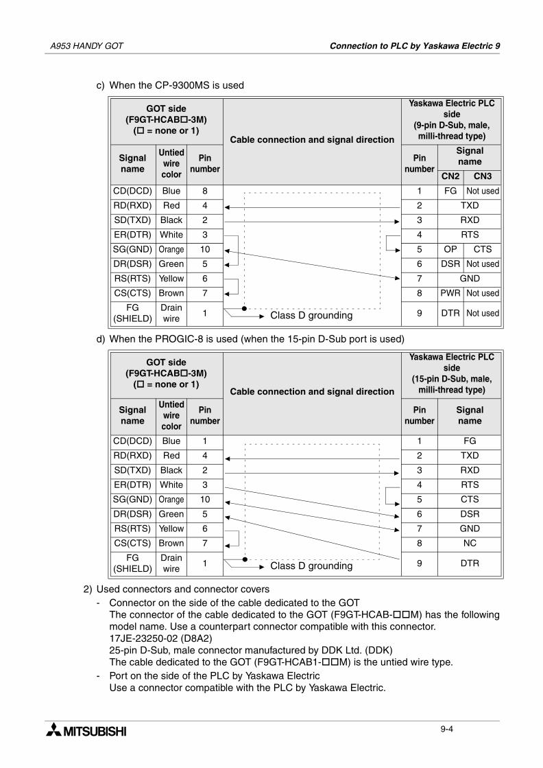
A953 HANDY GOT Connection to PLC by Yaskawa Electric 9
c) When the CP-9300MS is used
d) When the PROGIC-8 is used (when the 15-pin D-Sub port is used)
2) Used connectors and connector covers- Connector on the side of the cable dedicated to the GOT
The connector of the cable dedicated to the GOT (F9GT-HCAB- M) has the followingmodel name. Use a counterpart connector compatible with this connector.17JE-23250-02 (D8A2)25-pin D-Sub, male connector manufactured by DDK Ltd. (DDK)The cable dedicated to the GOT (F9GT-HCAB1- M) is the untied wire type.
- Port on the side of the PLC by Yaskawa ElectricUse a connector compatible with the PLC by Yaskawa Electric.
GOT side(F9GT-HCAB -3M)
( = none or 1)Cable connection and signal direction
Yaskawa Electric PLC side
(9-pin D-Sub, male, milli-thread type)
Signalname
Untiedwirecolor
Pinnumber
Pinnumber
Signalname
CN2 CN3
CD(DCD) Blue 8 1 FG Not used
RD(RXD) Red 4 2 TXD
SD(TXD) Black 2 3 RXD
ER(DTR) White 3 4 RTS
SG(GND) Orange 10 5 OP CTS
DR(DSR) Green 5 6 DSR Not used
RS(RTS) Yellow 6 7 GND
CS(CTS) Brown 7 8 PWR Not used
FG(SHIELD)
Drain wire
1 9 DTR Not used
GOT side(F9GT-HCAB -3M)
( = none or 1)Cable connection and signal direction
Yaskawa Electric PLC side
(15-pin D-Sub, male, milli-thread type)
Signalname
Untiedwirecolor
Pinnumber
Pinnumber
Signalname
CD(DCD) Blue 1 1 FG
RD(RXD) Red 4 2 TXD
SD(TXD) Black 2 3 RXD
ER(DTR) White 3 4 RTS
SG(GND) Orange 10 5 CTS
DR(DSR) Green 5 6 DSR
RS(RTS) Yellow 6 7 GND
CS(CTS) Brown 7 8 NC
FG(SHIELD)
Drain wire
1 9 DTR
Class D grounding
Class D grounding
9-4
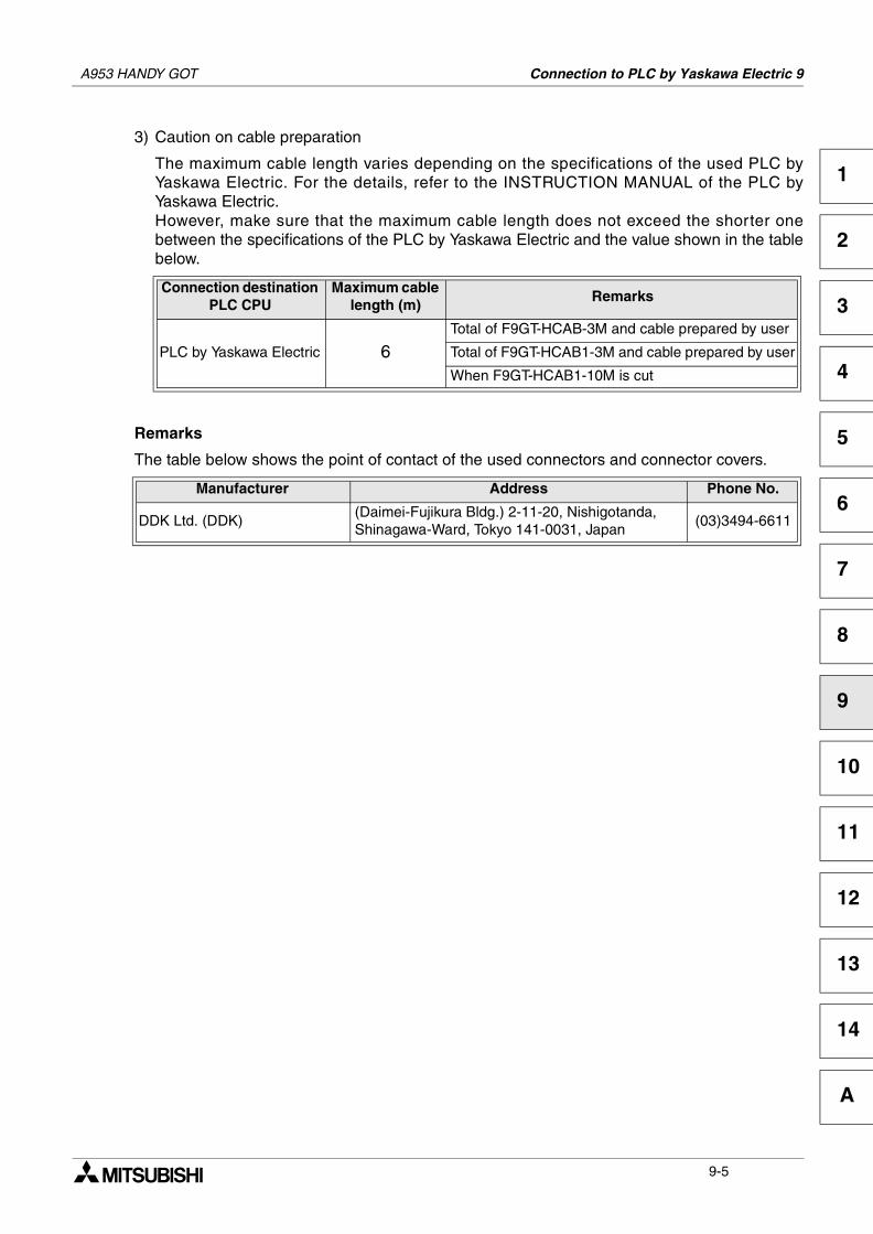
A953 HANDY GOT Connection to PLC by Yaskawa Electric 9
1
2
3
4
5
6
7
8
9
10
11
12
13
14
A
3) Caution on cable preparation
The maximum cable length varies depending on the specifications of the used PLC byYaskawa Electric. For the details, refer to the INSTRUCTION MANUAL of the PLC byYaskawa Electric.However, make sure that the maximum cable length does not exceed the shorter onebetween the specifications of the PLC by Yaskawa Electric and the value shown in the tablebelow.
Remarks
The table below shows the point of contact of the used connectors and connector covers.
Connection destination PLC CPU
Maximum cable length (m)
Remarks
PLC by Yaskawa Electric 6Total of F9GT-HCAB-3M and cable prepared by user
Total of F9GT-HCAB1-3M and cable prepared by user
When F9GT-HCAB1-10M is cut
Manufacturer Address Phone No.
DDK Ltd. (DDK)(Daimei-Fujikura Bldg.) 2-11-20, Nishigotanda,Shinagawa-Ward, Tokyo 141-0031, Japan
(03)3494-6611
9-5

A953 HANDY GOT Connection to PLC by Yaskawa Electric 9
MEMO
9-6
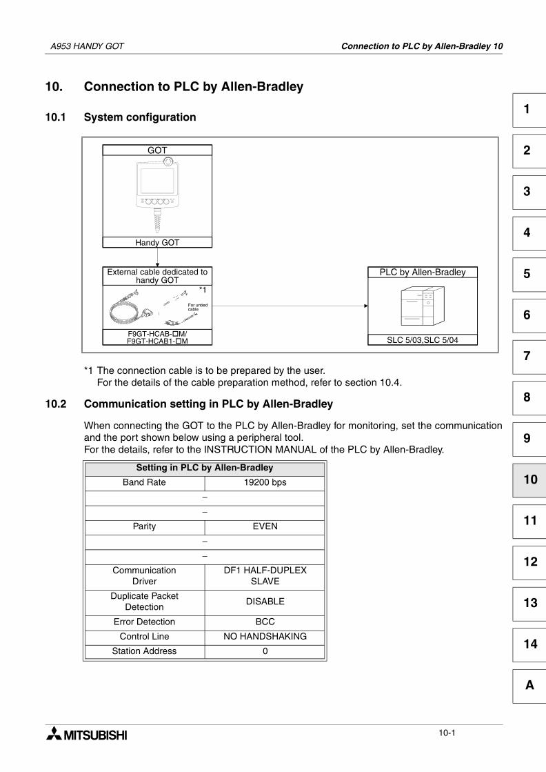
Connection to PLC by Allen-Bradley 10
1
2
3
4
5
6
7
8
9
10
11
12
13
14
A
10. Connection to PLC by Allen-Bradley
10.1 System configuration
*1 The connection cable is to be prepared by the user.For the details of the cable preparation method, refer to section 10.4.
10.2 Communication setting in PLC by Allen-Bradley
When connecting the GOT to the PLC by Allen-Bradley for monitoring, set the communicationand the port shown below using a peripheral tool.For the details, refer to the INSTRUCTION MANUAL of the PLC by Allen-Bradley.
Setting in PLC by Allen-Bradley
Band Rate 19200 bps
−−
Parity EVEN
−−
CommunicationDriver
DF1 HALF-DUPLEXSLAVE
Duplicate PacketDetection
DISABLE
Error Detection BCC
Control Line NO HANDSHAKING
Station Address 0
GOT
Handy GOT
PLC by Allen-Bradley
SLC 5/03,SLC 5/04F9GT-HCAB- M/F9GT-HCAB1- M
*1
For untiedcable
External cable dedicated tohandy GOT
A953 HANDY GOT
10-1
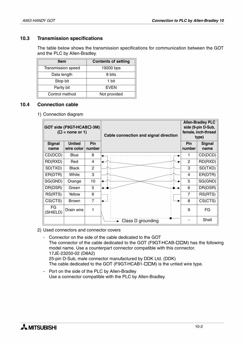
A953 HANDY GOT Connection to PLC by Allen-Bradley 10
10.3 Transmission specifications
The table below shows the transmission specifications for communication between the GOTand the PLC by Allen-Bradley.
10.4 Connection cable
1) Connection diagram
2) Used connectors and connector covers
- Connector on the side of the cable dedicated to the GOTThe connector of the cable dedicated to the GOT (F9GT-HCAB- M) has the followingmodel name. Use a counterpart connector compatible with this connector.17JE-23250-02 (D8A2)25-pin D-Sub, male connector manufactured by DDK Ltd. (DDK)The cable dedicated to the GOT (F9GT-HCAB1- M) is the untied wire type.
- Port on the side of the PLC by Allen-BradleyUse a connector compatible with the PLC by Allen-Bradley.
Item Contents of setting
Transmission speed 19200 bps
Data length 8 bits
Stop bit 1 bit
Parity bit EVEN
Control method Not provided
GOT side (F9GT-HCAB -3M)( = none or 1)
Cable connection and signal direction
Allen-Bradley PLC side (9-pin D-Sub,
female, inch-thread type)
Signalname
Untied wire color
Pinnumber
Pinnumber
Signalname
CD(DCD) Blue 8 1 CD(DCD)
RD(RXD) Red 4 2 RD(RXD)
SD(TXD) Black 2 3 SD(TXD)
ER(DTR) White 3 4 ER(DTR)
SG(GND) Orange 10 5 SG(GND)
DR(DSR) Green 5 6 DR(DSR)
RS(RTS) Yellow 6 7 RS(RTS)
CS(CTS) Brown 7 8 CS(CTS)
FG(SHIELD)
Drain wire 1 9 FG
− ShellClass D grounding
10-2
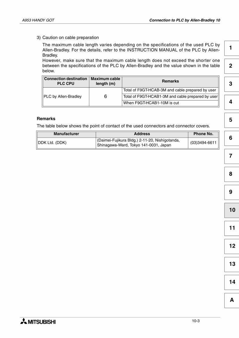
A953 HANDY GOT Connection to PLC by Allen-Bradley 10
1
2
3
4
5
6
7
8
9
10
11
12
13
14
A
3) Caution on cable preparation
The maximum cable length varies depending on the specifications of the used PLC byAllen-Bradley. For the details, refer to the INSTRUCTION MANUAL of the PLC by Allen-Bradley.However, make sure that the maximum cable length does not exceed the shorter onebetween the specifications of the PLC by Allen-Bradley and the value shown in the tablebelow.
Remarks
The table below shows the point of contact of the used connectors and connector covers.
Connection destination PLC CPU
Maximum cable length (m)
Remarks
PLC by Allen-Bradley 6Total of F9GT-HCAB-3M and cable prepared by user
Total of F9GT-HCAB1-3M and cable prepared by user
When F9GT-HCAB1-10M is cut
Manufacturer Address Phone No.
DDK Ltd. (DDK)(Daimei-Fujikura Bldg.) 2-11-20, Nishigotanda,Shinagawa-Ward, Tokyo 141-0031, Japan
(03)3494-6611
10-3

A953 HANDY GOT Connection to PLC by Allen-Bradley 10
MEMO
10-4
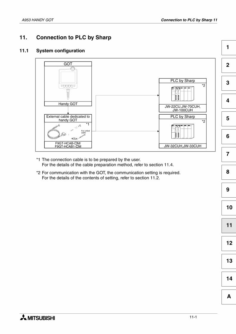
Connection to PLC by Sharp 11
1
2
3
4
5
6
7
8
9
10
11
12
13
14
A
11. Connection to PLC by Sharp
11.1 System configuration
*1 The connection cable is to be prepared by the user.For the details of the cable preparation method, refer to section 11.4.
*2 For communication with the GOT, the communication setting is required.For the details of the contents of setting, refer to section 11.2.
GOT
Handy GOT
PLC by Sharp
JW-22CU,JW-70CUH,JW-100CUH
PLC by Sharp
JW-32CUH,JW-33CUH
*2
*2*1
F9GT-HCAB- M/F9GT-HCAB1- M
For untiedcable
External cable dedicated tohandy GOT
A953 HANDY GOT
11-1
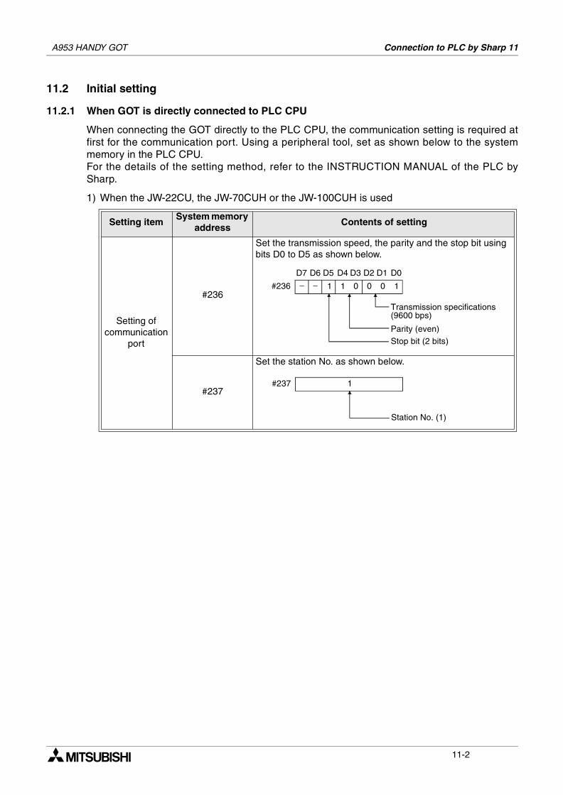
A953 HANDY GOT Connection to PLC by Sharp 11
11.2 Initial setting
11.2.1 When GOT is directly connected to PLC CPU
When connecting the GOT directly to the PLC CPU, the communication setting is required atfirst for the communication port. Using a peripheral tool, set as shown below to the systemmemory in the PLC CPU.For the details of the setting method, refer to the INSTRUCTION MANUAL of the PLC bySharp.
1) When the JW-22CU, the JW-70CUH or the JW-100CUH is used
Setting itemSystem memory
addressContents of setting
Setting of communication
port
#236
Set the transmission speed, the parity and the stop bit using bits D0 to D5 as shown below.
#237
Set the station No. as shown below.
− − 1 1 0 0 0 1
D6 D5 D4 D3 D2 D1 D0D7
#236
Transmission specifications(9600 bps)
Parity (even)Stop bit (2 bits)
1#237
Station No. (1)
11-2
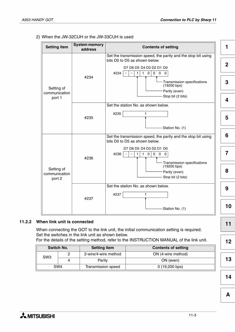
A953 HANDY GOT Connection to PLC by Sharp 11
1
2
3
4
5
6
7
8
9
10
11
12
13
14
A
2) When the JW-32CUH or the JW-33CUH is used
11.2.2 When link unit is connected
When connecting the GOT to the link unit, the initial communication setting is required.Set the switches in the link unit as shown below.For the details of the setting method, refer to the INSTRUCTION MANUAL of the link unit.
Setting itemSystem memory
addressContents of setting
Setting of communication
port 1
#234
Set the transmission speed, the parity and the stop bit using bits D0 to D5 as shown below.
#235
Set the station No. as shown below.
Setting of communication
port 2
#236
Set the transmission speed, the parity and the stop bit using bits D0 to D5 as shown below.
#237
Set the station No. as shown below.
Switch No. Setting item Contents of setting
SW32 2-wire/4-wire method ON (4-wire method)
4 Parity ON (even)
SW4 Transmission speed 0 (19,200 bps)
− − 1 1 0 0 0 0
D6 D5 D4 D3 D2 D1 D0D7
#234
Transmission specifications(19200 bps)
Parity (even)Stop bit (2 bits)
1#235
Station No. (1)
− − 1 1 0 0 0 0
D6 D5 D4 D3 D2 D1 D0D7
#236
Transmission specifications(19200 bps)
Parity (even)Stop bit (2 bits)
1#237
Station No. (1)
11-3
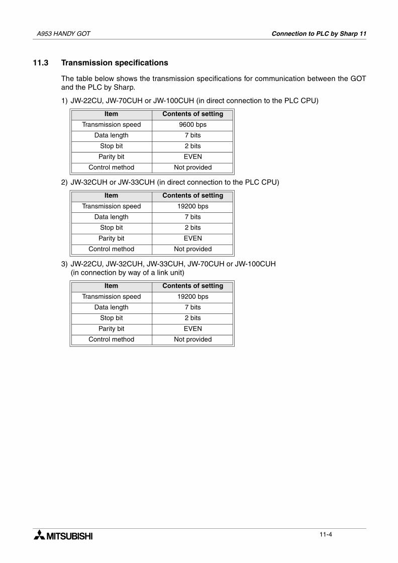
A953 HANDY GOT Connection to PLC by Sharp 11
11.3 Transmission specifications
The table below shows the transmission specifications for communication between the GOTand the PLC by Sharp.
1) JW-22CU, JW-70CUH or JW-100CUH (in direct connection to the PLC CPU)
2) JW-32CUH or JW-33CUH (in direct connection to the PLC CPU)
3) JW-22CU, JW-32CUH, JW-33CUH, JW-70CUH or JW-100CUH(in connection by way of a link unit)
Item Contents of setting
Transmission speed 9600 bps
Data length 7 bits
Stop bit 2 bits
Parity bit EVEN
Control method Not provided
Item Contents of setting
Transmission speed 19200 bps
Data length 7 bits
Stop bit 2 bits
Parity bit EVEN
Control method Not provided
Item Contents of setting
Transmission speed 19200 bps
Data length 7 bits
Stop bit 2 bits
Parity bit EVEN
Control method Not provided
11-4
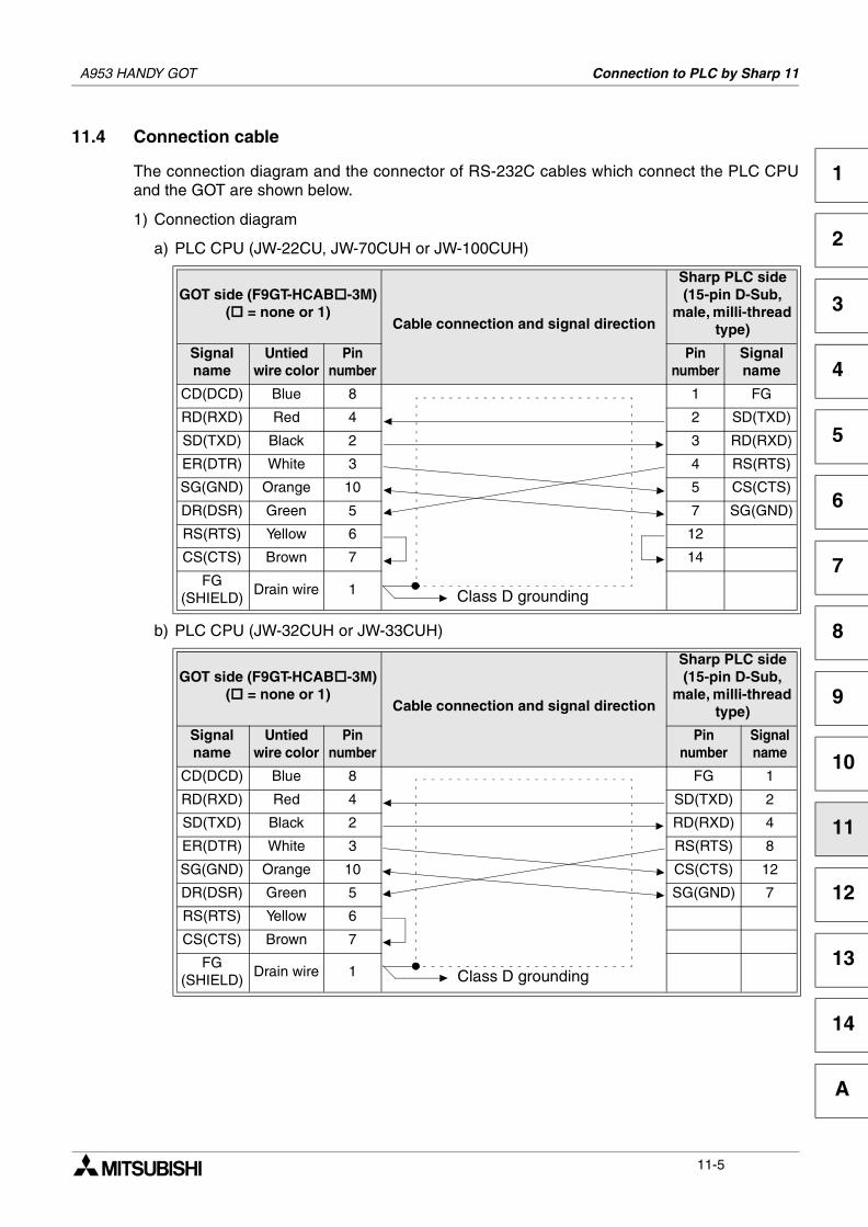
A953 HANDY GOT Connection to PLC by Sharp 11
1
2
3
4
5
6
7
8
9
10
11
12
13
14
A
11.4 Connection cable
The connection diagram and the connector of RS-232C cables which connect the PLC CPUand the GOT are shown below.
1) Connection diagram
a) PLC CPU (JW-22CU, JW-70CUH or JW-100CUH)
b) PLC CPU (JW-32CUH or JW-33CUH)
GOT side (F9GT-HCAB -3M)( = none or 1)
Cable connection and signal direction
Sharp PLC side (15-pin D-Sub,
male, milli-thread type)
Signalname
Untied wire color
Pinnumber
Pinnumber
Signalname
CD(DCD) Blue 8 1 FG
RD(RXD) Red 4 2 SD(TXD)
SD(TXD) Black 2 3 RD(RXD)
ER(DTR) White 3 4 RS(RTS)
SG(GND) Orange 10 5 CS(CTS)
DR(DSR) Green 5 7 SG(GND)
RS(RTS) Yellow 6 12
CS(CTS) Brown 7 14
FG(SHIELD)
Drain wire 1
GOT side (F9GT-HCAB -3M)( = none or 1)
Cable connection and signal direction
Sharp PLC side (15-pin D-Sub,
male, milli-thread type)
Signalname
Untied wire color
Pinnumber
Pinnumber
Signalname
CD(DCD) Blue 8 FG 1
RD(RXD) Red 4 SD(TXD) 2
SD(TXD) Black 2 RD(RXD) 4
ER(DTR) White 3 RS(RTS) 8
SG(GND) Orange 10 CS(CTS) 12
DR(DSR) Green 5 SG(GND) 7
RS(RTS) Yellow 6
CS(CTS) Brown 7
FG(SHIELD)
Drain wire 1
Class D grounding
Class D grounding
11-5
A953 HANDY GOT Connection to PLC by Sharp 11
2) Used connectors and connector covers
- Connector on the side of the cable dedicated to the GOTThe connector of the cable dedicated to the GOT (F9GT-HCAB- M) has the followingmodel name. Use a counterpart connector compatible with this connector.17JE-23250-02 (D8A2)25-pin D-Sub, male connector manufactured by DDK Ltd. (DDK)The cable dedicated to the GOT (F9GT-HCAB1- M) is the untied wire type.
- Port on the side of the PLC by SharpUse a connector compatible with the PLC by Sharp.
3) Caution on cable preparation
The maximum cable length varies depending on the specifications of the used PLC bySharp. For the details, refer to the INSTRUCTION MANUAL of the PLC by Sharp.However, make sure that the maximum cable length does not exceed the shorter onebetween the specifications of the PLC by Sharp and the value shown in the table below.
Remarks
The table below shows the point of contact of the used connectors and connector covers.
Connection destination PLC CPU
Maximum cable length (m)
Remarks
PLC by Sharp 6Total of F9GT-HCAB-3M and cable prepared by user
Total of F9GT-HCAB1-3M and cable prepared by user
When F9GT-HCAB1-10M is cut
Manufacturer Address Phone No.
DDK Ltd. (DDK)(Daimei-Fujikura Bldg.) 2-11-20, Nishigotanda,Shinagawa-Ward, Tokyo 141-0031, Japan
(03)3494-6611
11-6
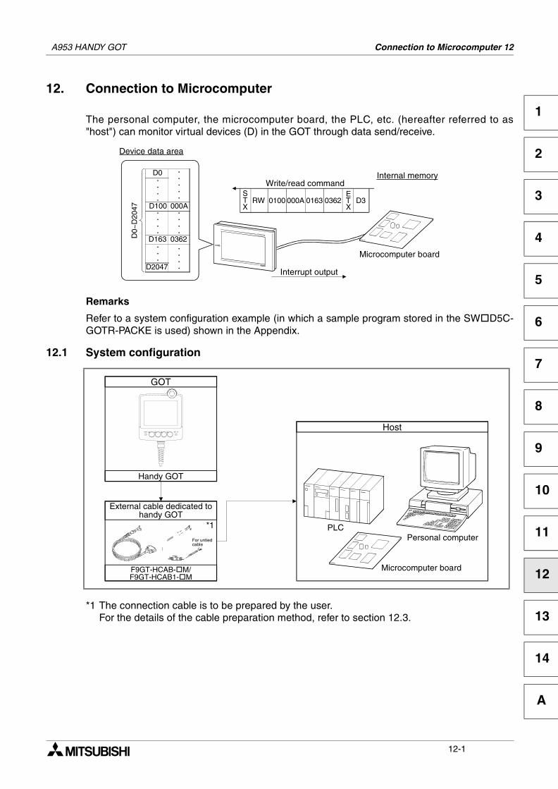
Connection to Microcomputer 12
1
2
3
4
5
6
7
8
9
10
11
12
13
14
A
12. Connection to Microcomputer
The personal computer, the microcomputer board, the PLC, etc. (hereafter referred to as"host") can monitor virtual devices (D) in the GOT through data send/receive.
Remarks
Refer to a system configuration example (in which a sample program stored in the SW D5C-GOTR-PACKE is used) shown in the Appendix.
12.1 System configuration
*1 The connection cable is to be prepared by the user.For the details of the cable preparation method, refer to section 12.3.
Write/read commandSTX
RW 0100 000A 0163 0362ETX
D3
D0
D100
D2047
.
.
.
.
D163
.
.
.
.
.
.
.
000A
0362
.
.
.
.
.
.
.
.
D0~
D20
47
Device data area
Interrupt output
.
.
.
.
.
Microcomputer board
Internal memory
GOT
Handy GOT
Host
Personal computerPLC
Microcomputer board
*1
F9GT-HCAB- M/F9GT-HCAB1- M
For untiedcable
External cable dedicated tohandy GOT
A953 HANDY GOT
12-1
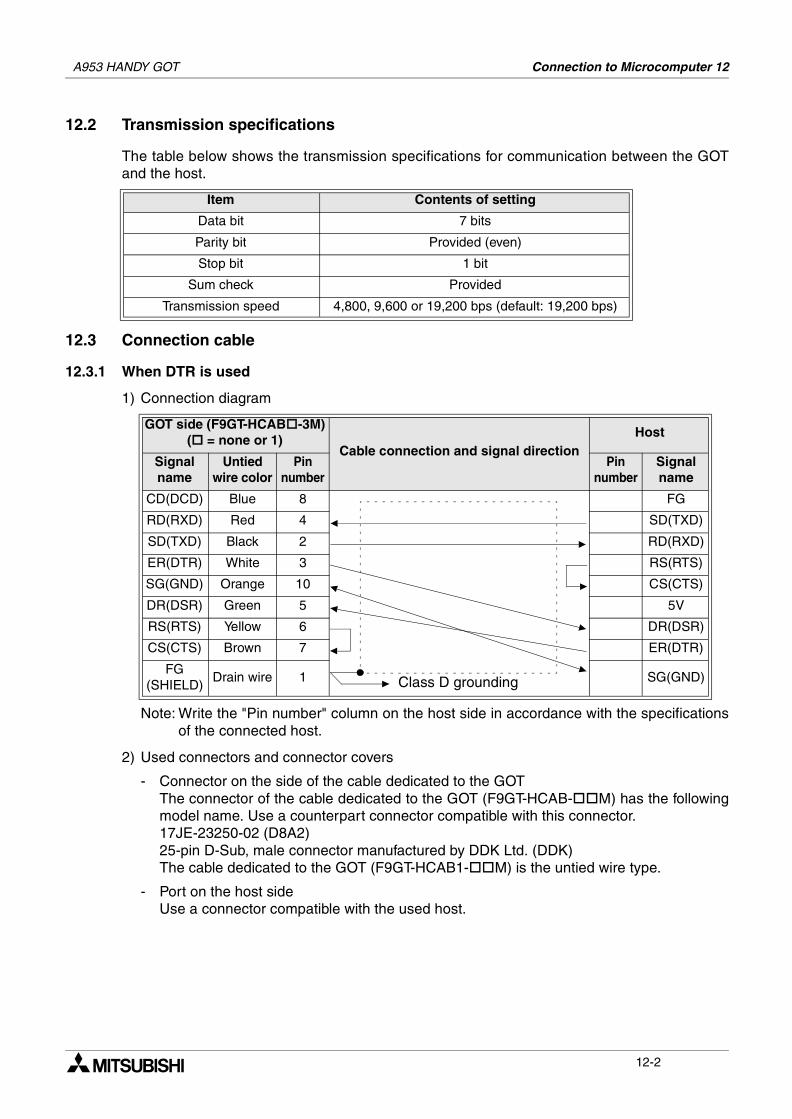
A953 HANDY GOT Connection to Microcomputer 12
12.2 Transmission specifications
The table below shows the transmission specifications for communication between the GOTand the host.
12.3 Connection cable
12.3.1 When DTR is used
1) Connection diagram
Note: Write the "Pin number" column on the host side in accordance with the specificationsof the connected host.
2) Used connectors and connector covers
- Connector on the side of the cable dedicated to the GOTThe connector of the cable dedicated to the GOT (F9GT-HCAB- M) has the followingmodel name. Use a counterpart connector compatible with this connector.17JE-23250-02 (D8A2)25-pin D-Sub, male connector manufactured by DDK Ltd. (DDK)The cable dedicated to the GOT (F9GT-HCAB1- M) is the untied wire type.
- Port on the host sideUse a connector compatible with the used host.
Item Contents of setting
Data bit 7 bits
Parity bit Provided (even)
Stop bit 1 bit
Sum check Provided
Transmission speed 4,800, 9,600 or 19,200 bps (default: 19,200 bps)
GOT side (F9GT-HCAB -3M)( = none or 1)
Cable connection and signal directionHost
Signalname
Untied wire color
Pinnumber
Pinnumber
Signalname
CD(DCD) Blue 8 FG
RD(RXD) Red 4 SD(TXD)
SD(TXD) Black 2 RD(RXD)
ER(DTR) White 3 RS(RTS)
SG(GND) Orange 10 CS(CTS)
DR(DSR) Green 5 5V
RS(RTS) Yellow 6 DR(DSR)
CS(CTS) Brown 7 ER(DTR)
FG(SHIELD)
Drain wire 1 SG(GND)Class D grounding
12-2
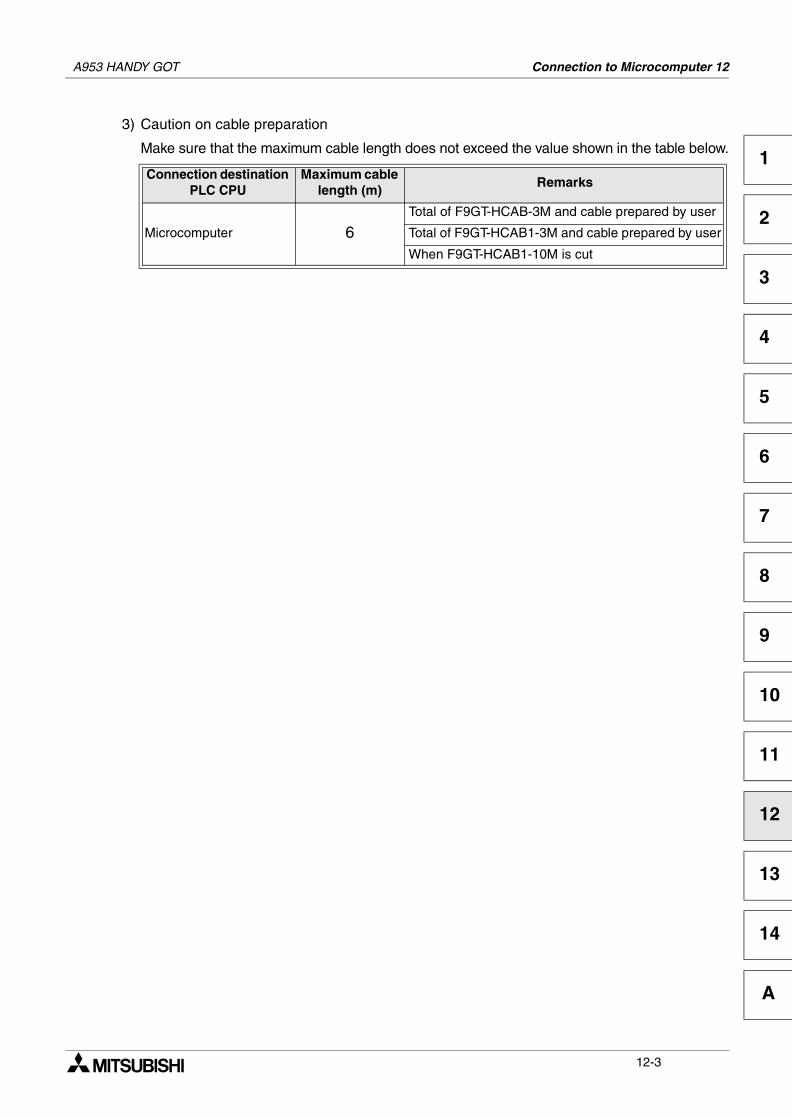
A953 HANDY GOT Connection to Microcomputer 12
1
2
3
4
5
6
7
8
9
10
11
12
13
14
A
3) Caution on cable preparation
Make sure that the maximum cable length does not exceed the value shown in the table below.
Connection destination PLC CPU
Maximum cable length (m)
Remarks
Microcomputer 6Total of F9GT-HCAB-3M and cable prepared by user
Total of F9GT-HCAB1-3M and cable prepared by user
When F9GT-HCAB1-10M is cut
12-3
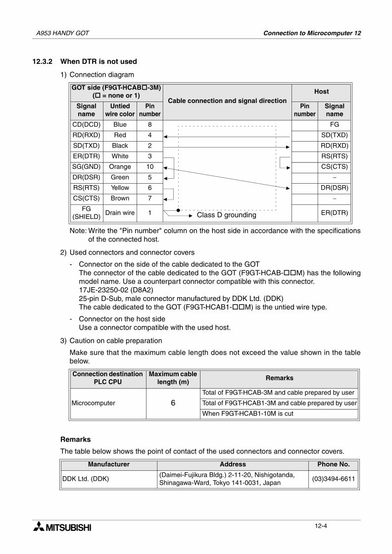
A953 HANDY GOT Connection to Microcomputer 12
12.3.2 When DTR is not used
1) Connection diagram
Note: Write the "Pin number" column on the host side in accordance with the specificationsof the connected host.
2) Used connectors and connector covers
- Connector on the side of the cable dedicated to the GOTThe connector of the cable dedicated to the GOT (F9GT-HCAB- M) has the followingmodel name. Use a counterpart connector compatible with this connector.17JE-23250-02 (D8A2)25-pin D-Sub, male connector manufactured by DDK Ltd. (DDK)The cable dedicated to the GOT (F9GT-HCAB1- M) is the untied wire type.
- Connector on the host sideUse a connector compatible with the used host.
3) Caution on cable preparation
Make sure that the maximum cable length does not exceed the value shown in the tablebelow.
Remarks
The table below shows the point of contact of the used connectors and connector covers.
GOT side (F9GT-HCAB -3M)( = none or 1)
Cable connection and signal directionHost
Signalname
Untied wire color
Pinnumber
Pinnumber
Signalname
CD(DCD) Blue 8 FG
RD(RXD) Red 4 SD(TXD)
SD(TXD) Black 2 RD(RXD)
ER(DTR) White 3 RS(RTS)
SG(GND) Orange 10 CS(CTS)
DR(DSR) Green 5 −RS(RTS) Yellow 6 DR(DSR)
CS(CTS) Brown 7 −FG
(SHIELD)Drain wire 1 ER(DTR)
Connection destination PLC CPU
Maximum cable length (m)
Remarks
Microcomputer 6Total of F9GT-HCAB-3M and cable prepared by user
Total of F9GT-HCAB1-3M and cable prepared by user
When F9GT-HCAB1-10M is cut
Manufacturer Address Phone No.
DDK Ltd. (DDK)(Daimei-Fujikura Bldg.) 2-11-20, Nishigotanda,Shinagawa-Ward, Tokyo 141-0031, Japan
(03)3494-6611
Class D grounding
12-4
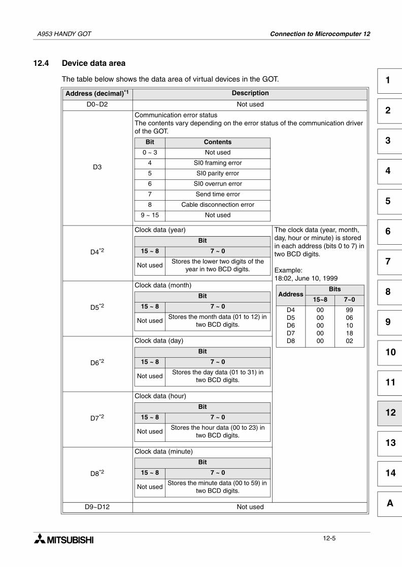
A953 HANDY GOT Connection to Microcomputer 12
1
2
3
4
5
6
7
8
9
10
11
12
13
14
A
12.4 Device data area
The table below shows the data area of virtual devices in the GOT.
Address (decimal)*1 Description
D0~D2 Not used
D3
Communication error statusThe contents vary depending on the error status of the communication driver of the GOT.
D4*2
Clock data (year) The clock data (year, month, day, hour or minute) is stored in each address (bits 0 to 7) in two BCD digits.
Example:18:02, June 10, 1999
D5*2
Clock data (month)
D6*2
Clock data (day)
D7*2
Clock data (hour)
D8*2
Clock data (minute)
D9~D12 Not used
Bit Contents
0 ~ 3 Not used
4 SI0 framing error
5 SI0 parity error
6 SI0 overrun error
7 Send time error
8 Cable disconnection error
9 ~ 15 Not used
Bit
15 ~ 8 7 ~ 0
Not usedStores the lower two digits of the
year in two BCD digits.
AddressBits
15~8 7~0
D4D5D6D7D8
0000000000
9906101802
Bit
15 ~ 8 7 ~ 0
Not usedStores the month data (01 to 12) in
two BCD digits.
Bit
15 ~ 8 7 ~ 0
Not usedStores the day data (01 to 31) in
two BCD digits.
Bit
15 ~ 8 7 ~ 0
Not usedStores the hour data (00 to 23) in
two BCD digits.
Bit
15 ~ 8 7 ~ 0
Not usedStores the minute data (00 to 59) in
two BCD digits.
12-5
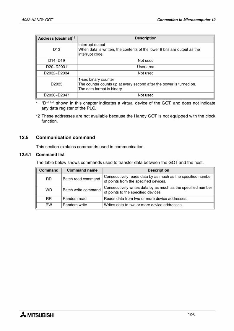
A953 HANDY GOT Connection to Microcomputer 12
*1 "D****" shown in this chapter indicates a virtual device of the GOT, and does not indicateany data register of the PLC.
*2 These addresses are not available because the Handy GOT is not equipped with the clockfunction.
12.5 Communication command
This section explains commands used in communication.
12.5.1 Command list
The table below shows commands used to transfer data between the GOT and the host.
D13Interrupt outputWhen data is written, the contents of the lower 8 bits are output as the interrupt code.
D14~D19 Not used
D20~D2031 User area
D2032~D2034 Not used
D20351-sec binary counterThe counter counts up at every second after the power is turned on.The data format is binary.
D2036~D2047 Not used
Command Command name Description
RD Batch read commandConsecutively reads data by as much as the specified number of points from the specified devices.
WD Batch write commandConsecutively writes data by as much as the specified number of points to the specified devices.
RR Random read Reads data from two or more device addresses.
RW Random write Writes data to two or more device addresses.
Address (decimal)*1 Description
12-6
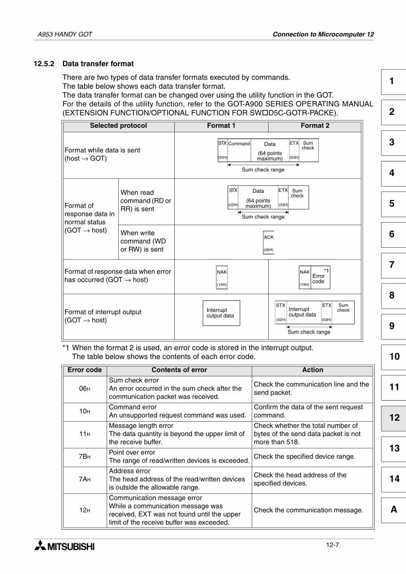
A953 HANDY GOT Connection to Microcomputer 12
1
2
3
4
5
6
7
8
9
10
11
12
13
14
A
12.5.2 Data transfer format
There are two types of data transfer formats executed by commands.The table below shows each data transfer format.The data transfer format can be changed over using the utility function in the GOT.For the details of the utility function, refer to the GOT-A900 SERIES OPERATING MANUAL(EXTENSION FUNCTION/OPTIONAL FUNCTION FOR SW D5C-GOTR-PACKE).
*1 When the format 2 is used, an error code is stored in the interrupt output.The table below shows the contents of each error code.
Selected protocol Format 1 Format 2
Format while data is sent(host → GOT)
Format of response data in normal status(GOT → host)
When read command (RD or RR) is sent
When write command (WD or RW) is sent
Format of response data when error has occurred (GOT → host)
Format of interrupt output(GOT → host)
Error code Contents of error Action
06H
Sum check errorAn error occurred in the sum check after the communication packet was received.
Check the communication line and the send packet.
10HCommand errorAn unsupported request command was used.
Confirm the data of the sent request command.
11H
Message length errorThe data quantity is beyond the upper limit of the receive buffer.
Check whether the total number of bytes of the send data packet is not more than 518.
7BHPoint over errorThe range of read/written devices is exceeded.
Check the specified device range.
7AH
Address errorThe head address of the read/written devices is outside the allowable range.
Check the head address of the specified devices.
12H
Communication message errorWhile a communication message was received, EXT was not found until the upper limit of the receive buffer was exceeded.
Check the communication message.
(02H)
STX Command Data
(64 pointsmaximum) (03H)
ETX Sumcheck
Sum check range
(02H)
STX Data
(64 pointsmaximum) (03H)
ETX Sumcheck
Sum check range
(06H)
ACK
(15H)
NAK
(15H)
NAK *1Errorcode
Interruptoutput data
(02H)
STX
(03H)
ETX Sumcheck
Sum check range
Interruptoutput data
12-7
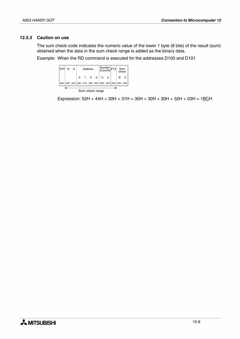
A953 HANDY GOT Connection to Microcomputer 12
12.5.3 Caution on use
The sum check code indicates the numeric value of the lower 1 byte (8 bits) of the result (sum)obtained when the data in the sum check range is added as the binary data.
Example: When the RD command is executed for the addresses D100 and D101
Expression: 52H + 44H + 30H + 31H + 30H + 30H + 30H + 32H + 03H = 1BCH
B
02H
STX
52H
R
44H
D
30H
Address
31H 30H 30H 30H 32H 03H
Numberof points ETX Sum
check
43H
C00010
Sum check range
2
42H
12-8
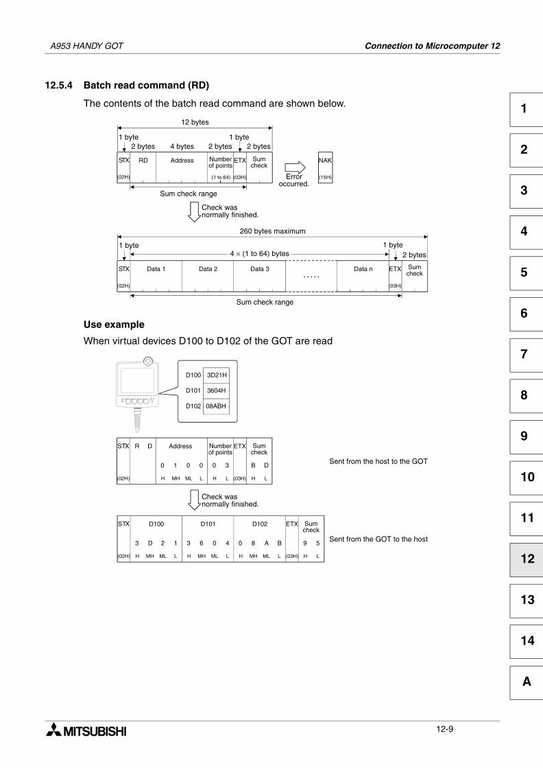
A953 HANDY GOT Connection to Microcomputer 12
1
2
3
4
5
6
7
8
9
10
11
12
13
14
A
12.5.4 Batch read command (RD)
The contents of the batch read command are shown below.
Use example
When virtual devices D100 to D102 of the GOT are read
(02H)
STX Address
(1 to 64)
Numberof points
Sumcheck
Sum check range
(03H)
ETXRD
2 bytes 4 bytes 2 bytes1 byte
2 bytes
12 bytes
(15H)
NAK
Erroroccurred.
(02H)
STX Sumcheck
Sum check range
(03H)
ETXData 1
1 byte2 bytes
260 bytes maximum
Data 2 Data 3 Data n
1 byte4 × (1 to 64) bytes
1 byte
Check wasnormally finished.
. . . . .
B
(02H)
STX R D
H
Address
MH ML L H L (03H)
Numberof points
ETX Sumcheck
L
D00010 3
H
9
(02H)
STX
H
D100
MH ML L H MH (03H)
D101 ETX Sumcheck
L
5312D3 6
HML
0
L
4
H
0
MH
8
ML
A
L
B
D102
Check wasnormally finished.
Sent from the host to the GOT
Sent from the GOT to the host
D100 3D21H
D101 3604H
D102 08ABH
12-9
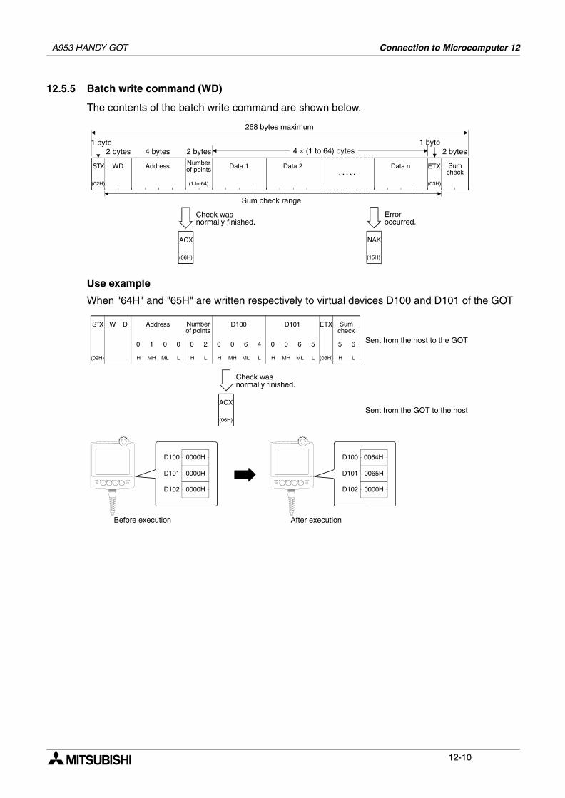
A953 HANDY GOT Connection to Microcomputer 12
12.5.5 Batch write command (WD)
The contents of the batch write command are shown below.
Use example
When "64H" and "65H" are written respectively to virtual devices D100 and D101 of the GOT
(02H)
STX Sumcheck
Sum check range
(03H)
ETXAddress
1 byte2 bytes
268 bytes maximum
Data 1 Data 2 Data n
1 byte4 × (1 to 64) bytes
. . . . .WD Number
of points
2 bytes 4 bytes 2 bytes
(1 to 64)
(06H)
ACX
Check wasnormally finished.
(15H)
NAK
Erroroccurred.
5
(02H)
STX W D
H
Address
MH ML L H L (03H)
Numberof points
ETX Sumcheck
L
600010 2
H
Sent from the host to the GOT
Sent from the GOT to the host
H
0
MH
0
ML
6
L
4
H
0
MH
0
ML
6
L
5
D100 D101
(06H)
ACX
Check wasnormally finished.
Before execution After execution
D100 0000H
D101 0000H
D102 0000H
D100 0064H
D101 0065H
D102 0000H
12-10
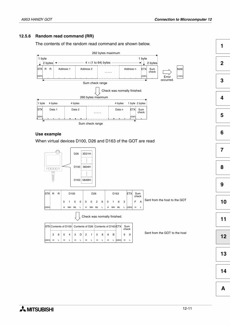
A953 HANDY GOT Connection to Microcomputer 12
1
2
3
4
5
6
7
8
9
10
11
12
13
14
A
12.5.6 Random read command (RR)
The contents of the random read command are shown below.
Use example
When virtual devices D100, D26 and D163 of the GOT are read
(02H)
STX Sumcheck
Sum check range
(03H)
ETX
1 byte2 bytes
262 bytes maximum
Address 1 Address 2 Address n
1 byte4 × (1 to 64) bytes
. . . . .R R
2 bytes
(15H)
NAK
Erroroccurred.
(02H)
STX Sumcheck
Sum check range
(03H)
ETX
1 byte 2 bytes
260 bytes maximum
Data 1 Data 2 Data n
1 byte
. . . . .
4 bytes 4 bytes 4 bytes
Check was normally finished.
F
(02H)
STX R
H
D100
MH ML L (03H)
ETX Sumcheck
L
A0010
H
9
(02H)
STX
H
Contents of D100
L H L H L (03H)
Contents of D26 ETX Sumcheck
L
934063 D
HH
2
L
1
H
0
L
8
H
A
L
B
Contents of D163
Check was normally finished.
Sent from the host to the GOT
Sent from the GOT to the host
H
0
MH
0
ML
2
L
6
H
0
MH
1
ML
6
L
3
D26 D163R
D26 3D21H
D100 3604H
D163 08ABH
. . .
. . .
12-11
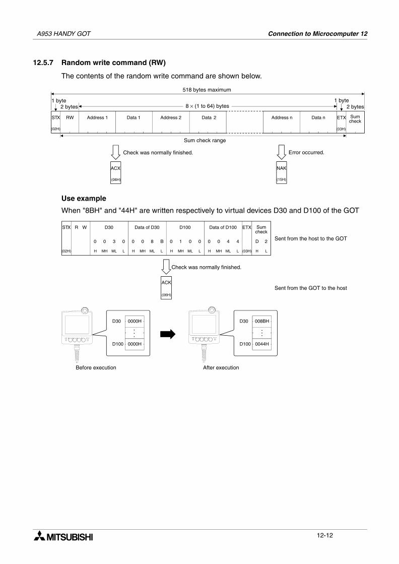
A953 HANDY GOT Connection to Microcomputer 12
12.5.7 Random write command (RW)
The contents of the random write command are shown below.
Use example
When "8BH" and "44H" are written respectively to virtual devices D30 and D100 of the GOT
(06H)
ACX
(02H)
STX Sumcheck
Sum check range
(03H)
ETXAddress 1
1 byte2 bytes
518 bytes maximum
Address 2 Data 2
1 byte8 × (1 to 64) bytes
Check was normally finished.
RW Data 1
2 bytes
(15H)
NAK
Error occurred.
Data nAddress n
D
(02H)
STX R W
H
D30
MH ML L H MH (03H)
Data of D30 ETX Sumcheck
L
200300 0
H
Sent from the host to the GOT
Sent from the GOT to the host
H
0
MH
1
ML
0
L
0
H
0
MH
0
ML
4
L
4
D100 Data of D100
(06H)
ACK
Check was normally finished.
ML
8
L
B
Before execution After execution
D30 0000H
D100 0000H
.
.
.
D30 008BH
. . .
D100 0044H
12-12
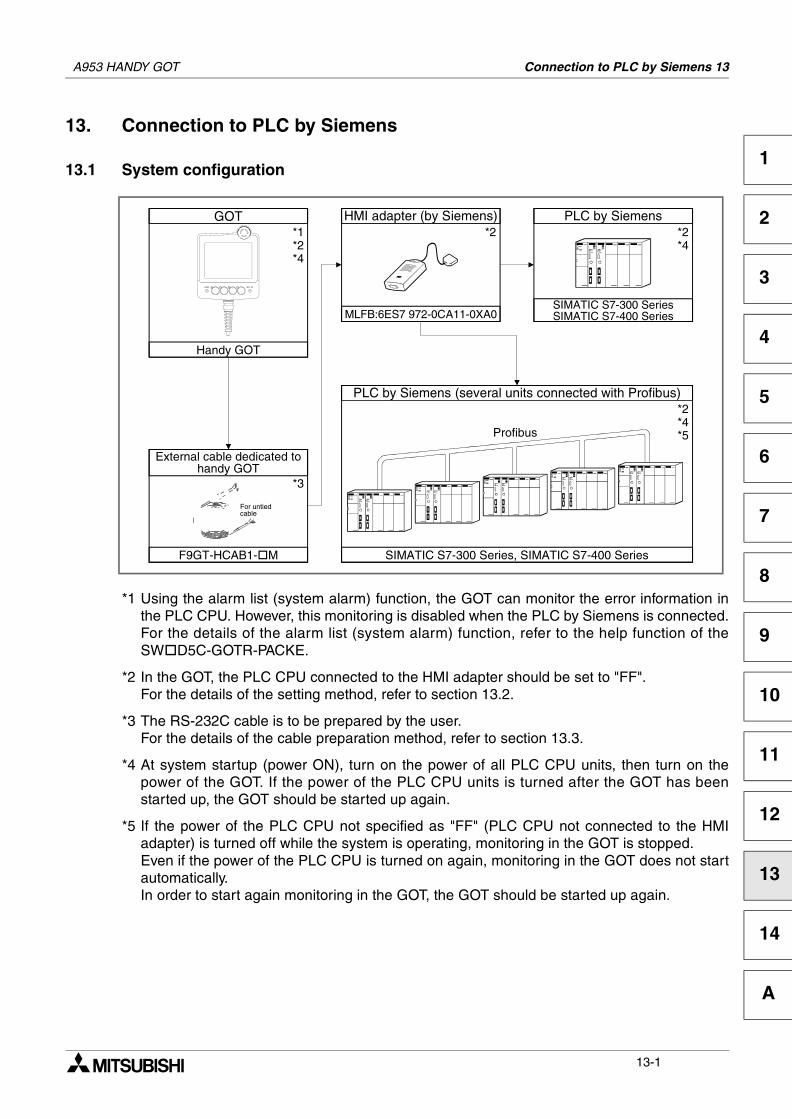
Connection to PLC by Siemens 13
1
2
3
4
5
6
7
8
9
10
11
12
13
14
A
13. Connection to PLC by Siemens
13.1 System configuration
*1 Using the alarm list (system alarm) function, the GOT can monitor the error information inthe PLC CPU. However, this monitoring is disabled when the PLC by Siemens is connected.For the details of the alarm list (system alarm) function, refer to the help function of theSW D5C-GOTR-PACKE.
*2 In the GOT, the PLC CPU connected to the HMI adapter should be set to "FF".For the details of the setting method, refer to section 13.2.
*3 The RS-232C cable is to be prepared by the user.For the details of the cable preparation method, refer to section 13.3.
*4 At system startup (power ON), turn on the power of all PLC CPU units, then turn on thepower of the GOT. If the power of the PLC CPU units is turned after the GOT has beenstarted up, the GOT should be started up again.
*5 If the power of the PLC CPU not specified as "FF" (PLC CPU not connected to the HMIadapter) is turned off while the system is operating, monitoring in the GOT is stopped.Even if the power of the PLC CPU is turned on again, monitoring in the GOT does not startautomatically.In order to start again monitoring in the GOT, the GOT should be started up again.
GOT
Handy GOT
PLC by Siemens
SIMATIC S7-300 SeriesSIMATIC S7-400 Series
HMI adapter (by Siemens)
MLFB:6ES7 972-0CA11-0XA0
PLC by Siemens (several units connected with Profibus)
SIMATIC S7-300 Series, SIMATIC S7-400 Series
*2*1*2*4
*2*4
*2*4*5Profibus
*3
F9GT-HCAB1- M
For untiedcable
External cable dedicated tohandy GOT
A953 HANDY GOT
13-1
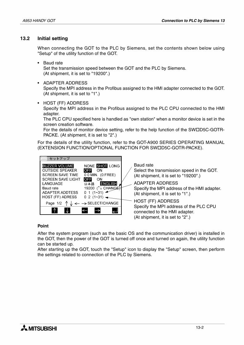
A953 HANDY GOT Connection to PLC by Siemens 13
13.2 Initial setting
When connecting the GOT to the PLC by Siemens, set the contents shown below using"Setup" of the utility function of the GOT.
• Baud rateSet the transmission speed between the GOT and the PLC by Siemens.(At shipment, it is set to "19200".)
• ADAPTER ADDRESSSpecify the MPI address in the Profibus assigned to the HMI adapter connected to the GOT.(At shipment, it is set to "1".)
• HOST (FF) ADDRESSSpecify the MPI address in the Profibus assigned to the PLC CPU connected to the HMIadapter.The PLC CPU specified here is handled as "own station" when a monitor device is set in thescreen creation software.For the details of monitor device setting, refer to the help function of the SW D5C-GOTR-PACKE. (At shipment, it is set to "2".)
For the details of the utility function, refer to the GOT-A900 SERIES OPERATING MANUAL(EXTENSION FUNCTION/OPTIONAL FUNCTION FOR SW D5C-GOTR-PACKE).
Point
After the system program (such as the basic OS and the communication driver) is installed inthe GOT, then the power of the GOT is turned off once and turned on again, the utility functioncan be started up.After starting up the GOT, touch the "Setup" icon to display the "Setup" screen, then performthe settings related to connection of the PLC by Siemens.
Baud rateSelect the transmission speed in the GOT.(At shipment, it is set to "19200".)
ADAPTER ADDRESSSpecify the MPI address of the HMI adapter. (At shipment, it is set to "1".)
HOST (FF) ADDRESSSpecify the MPI address of the PLC CPU connected to the HMI adapter.(At shipment, it is set to "2".)
13-2
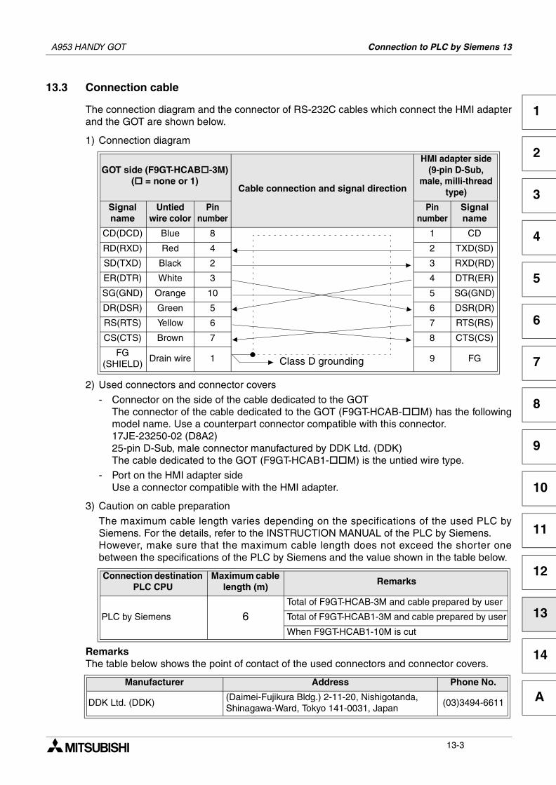
A953 HANDY GOT Connection to PLC by Siemens 13
1
2
3
4
5
6
7
8
9
10
11
12
13
14
A
13.3 Connection cable
The connection diagram and the connector of RS-232C cables which connect the HMI adapterand the GOT are shown below.
1) Connection diagram
2) Used connectors and connector covers
- Connector on the side of the cable dedicated to the GOTThe connector of the cable dedicated to the GOT (F9GT-HCAB- M) has the followingmodel name. Use a counterpart connector compatible with this connector.17JE-23250-02 (D8A2)25-pin D-Sub, male connector manufactured by DDK Ltd. (DDK)The cable dedicated to the GOT (F9GT-HCAB1- M) is the untied wire type.
- Port on the HMI adapter sideUse a connector compatible with the HMI adapter.
3) Caution on cable preparation
The maximum cable length varies depending on the specifications of the used PLC bySiemens. For the details, refer to the INSTRUCTION MANUAL of the PLC by Siemens.However, make sure that the maximum cable length does not exceed the shorter onebetween the specifications of the PLC by Siemens and the value shown in the table below.
RemarksThe table below shows the point of contact of the used connectors and connector covers.
GOT side (F9GT-HCAB -3M)( = none or 1)
Cable connection and signal direction
HMI adapter side(9-pin D-Sub,
male, milli-thread type)
Signalname
Untied wire color
Pinnumber
Pinnumber
Signalname
CD(DCD) Blue 8 1 CD
RD(RXD) Red 4 2 TXD(SD)
SD(TXD) Black 2 3 RXD(RD)
ER(DTR) White 3 4 DTR(ER)
SG(GND) Orange 10 5 SG(GND)
DR(DSR) Green 5 6 DSR(DR)
RS(RTS) Yellow 6 7 RTS(RS)
CS(CTS) Brown 7 8 CTS(CS)
FG(SHIELD)
Drain wire 1 9 FG
Connection destination PLC CPU
Maximum cable length (m)
Remarks
PLC by Siemens 6Total of F9GT-HCAB-3M and cable prepared by user
Total of F9GT-HCAB1-3M and cable prepared by user
When F9GT-HCAB1-10M is cut
Manufacturer Address Phone No.
DDK Ltd. (DDK)(Daimei-Fujikura Bldg.) 2-11-20, Nishigotanda,Shinagawa-Ward, Tokyo 141-0031, Japan
(03)3494-6611
Class D grounding
13-3

A953 HANDY GOT Connection to PLC by Siemens 13
MEMO
13-4
Diagnostics 14
1
2
3
4
5
6
7
8
9
10
11
12
13
14
A
14. Diagnostics
This section explains troubleshooting during operation.
Cautions on startup/maintenance
• Do not touch connectors while the power is ON.If a connector is touched, electrical shock or malfunction may be caused.
• Set to OFF the power before cleaning the Handy GOT or tightening a terminal.If the Handy GOT is cleaned or a terminal is tightened while the power is ON, you may getelectrical shock.
• Correctly connect the battery (for memory backup). Do not charge it, disassemble it, heat it,put it into fire or short-circuit it.Such handling may cause rupture or inflammation.
Cautions on startup/maintenance
• Do not disassemble or modify the Handy GOT.Disassembly or modification may cause failure, malfunction or fire.
• For replacement or repair of the backlight, consult with a Mitsubishi Electric distributor.
• Turn OFF the power before connecting or disconnecting a cable.Connecting or disconnecting a cable while the power is ON may cause failure ormalfunction.
14.1 When POWER LED does not light
The POWER LED in the Handy GOT is lit by the internal 5V DC power supply. If it does notlight, check the following points.If there is no abnormality in the cable connection, wiring, supply voltage or power capacity, thecircuits inside the Handy GOT may be damaged. Please consult with a Mitsubishi Electricdistributor.
• Check whether the wiring related to the power supply is executed correctly. (Refer to 2.2.5.)
• Check whether the supply voltage satisfies the specifications.[Allowable power range: 20.4 to 26.4V DC, power ripple: 200 mV or less] (Refer to 4.1.2.)
• Check whether the power capacity of the DC power supply is sufficient.[Current consumption: 24V DC, 400 mA] (Refer to 4.1.2.)
• Check whether external cables are connected correctly to the Handy GOT. (Refer to 2.2.2.)
A953 HANDY GOT
14-1
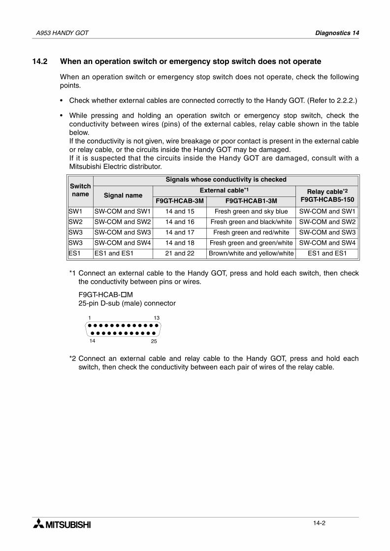
A953 HANDY GOT Diagnostics 14
14.2 When an operation switch or emergency stop switch does not operate
When an operation switch or emergency stop switch does not operate, check the followingpoints.
• Check whether external cables are connected correctly to the Handy GOT. (Refer to 2.2.2.)
• While pressing and holding an operation switch or emergency stop switch, check theconductivity between wires (pins) of the external cables, relay cable shown in the tablebelow. If the conductivity is not given, wire breakage or poor contact is present in the external cableor relay cable, or the circuits inside the Handy GOT may be damaged. If it is suspected that the circuits inside the Handy GOT are damaged, consult with aMitsubishi Electric distributor.
*1 Connect an external cable to the Handy GOT, press and hold each switch, then checkthe conductivity between pins or wires.
F9GT-HCAB- M25-pin D-sub (male) connector
*2 Connect an external cable and relay cable to the Handy GOT, press and hold eachswitch, then check the conductivity between each pair of wires of the relay cable.
Switchname
Signals whose conductivity is checked
Signal nameExternal cable*1 Relay cable*2
F9GT-HCAB5-150F9GT-HCAB-3M F9GT-HCAB1-3M
SW1 SW-COM and SW1 14 and 15 Fresh green and sky blue SW-COM and SW1
SW2 SW-COM and SW2 14 and 16 Fresh green and black/white SW-COM and SW2
SW3 SW-COM and SW3 14 and 17 Fresh green and red/white SW-COM and SW3
SW3 SW-COM and SW4 14 and 18 Fresh green and green/white SW-COM and SW4
ES1 ES1 and ES1 21 and 22 Brown/white and yellow/white ES1 and ES1
1 13
14 25
14-2
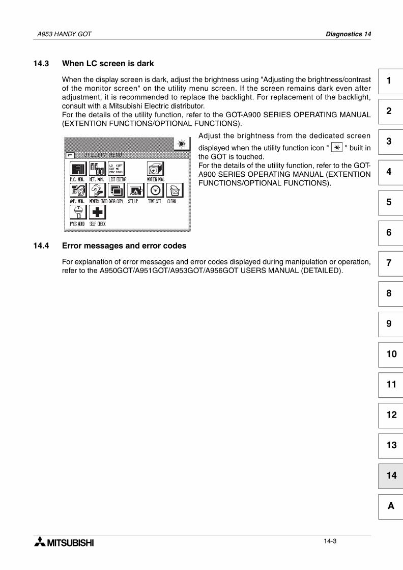
A953 HANDY GOT Diagnostics 14
1
2
3
4
5
6
7
8
9
10
11
12
13
14
A
14.3 When LC screen is dark
When the display screen is dark, adjust the brightness using "Adjusting the brightness/contrastof the monitor screen" on the utility menu screen. If the screen remains dark even afteradjustment, it is recommended to replace the backlight. For replacement of the backlight,consult with a Mitsubishi Electric distributor.For the details of the utility function, refer to the GOT-A900 SERIES OPERATING MANUAL(EXTENTION FUNCTIONS/OPTIONAL FUNCTIONS).
Adjust the brightness from the dedicated screen
displayed when the utility function icon " " built inthe GOT is touched. For the details of the utility function, refer to the GOT-A900 SERIES OPERATING MANUAL (EXTENTIONFUNCTIONS/OPTIONAL FUNCTIONS).
14.4 Error messages and error codes
For explanation of error messages and error codes displayed during manipulation or operation,refer to the A950GOT/A951GOT/A953GOT/A956GOT USERS MANUAL (DETAILED).
14-3

A953 HANDY GOT Diagnostics 14
MEMO
14-4
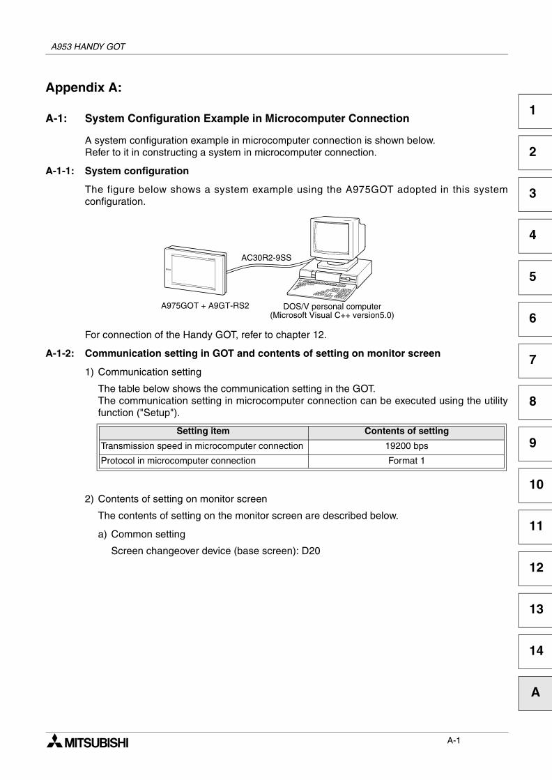
1
2
3
4
5
6
7
8
9
10
11
12
13
14
A
Appendix A:
A-1: System Configuration Example in Microcomputer Connection
A system configuration example in microcomputer connection is shown below.Refer to it in constructing a system in microcomputer connection.
A-1-1: System configuration
The figure below shows a system example using the A975GOT adopted in this systemconfiguration.
For connection of the Handy GOT, refer to chapter 12.
A-1-2: Communication setting in GOT and contents of setting on monitor screen
1) Communication setting
The table below shows the communication setting in the GOT.The communication setting in microcomputer connection can be executed using the utilityfunction ("Setup").
2) Contents of setting on monitor screen
The contents of setting on the monitor screen are described below.
a) Common setting
Screen changeover device (base screen): D20
Setting item Contents of setting
Transmission speed in microcomputer connection 19200 bps
Protocol in microcomputer connection Format 1
A975GOT + A9GT-RS2 DOS/V personal computer(Microsoft Visual C++ version5.0)
AC30R2-9SS
A953 HANDY GOT
A-1
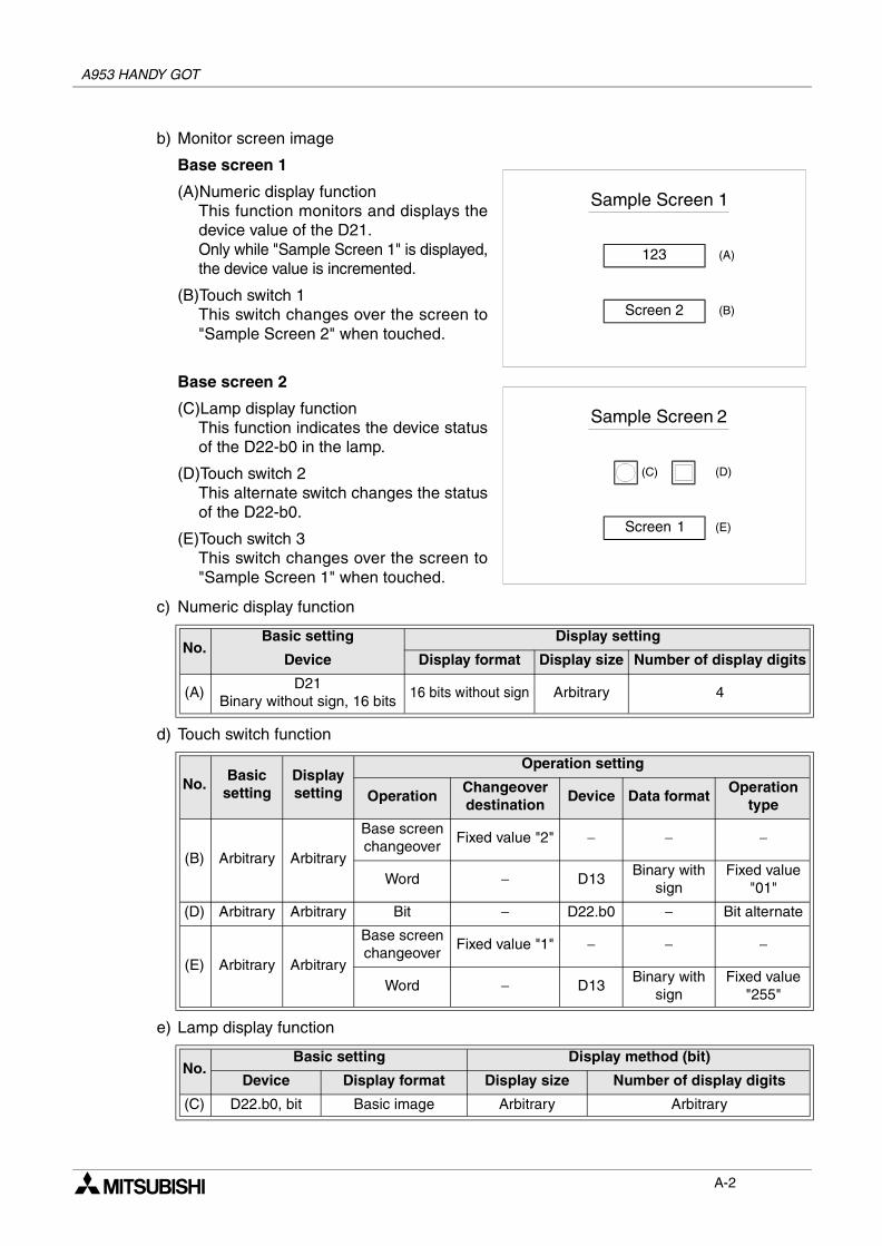
A953 HANDY GOT
b) Monitor screen image
Base screen 1
(A)Numeric display functionThis function monitors and displays thedevice value of the D21.Only while "Sample Screen 1" is displayed,the device value is incremented.
(B)Touch switch 1This switch changes over the screen to"Sample Screen 2" when touched.
Base screen 2
(C)Lamp display functionThis function indicates the device statusof the D22-b0 in the lamp.
(D)Touch switch 2This alternate switch changes the statusof the D22-b0.
(E)Touch switch 3This switch changes over the screen to"Sample Screen 1" when touched.
c) Numeric display function
d) Touch switch function
e) Lamp display function
No.Basic setting Display setting
Device Display format Display size Number of display digits
(A)D21
Binary without sign, 16 bits16 bits without sign Arbitrary 4
No.Basic
settingDisplaysetting
Operation setting
OperationChangeoverdestination
Device Data formatOperation
type
(B) Arbitrary Arbitrary
Base screenchangeover
Fixed value "2" − − −
Word − D13Binary with
signFixed value
"01"
(D) Arbitrary Arbitrary Bit − D22.b0 − Bit alternate
(E) Arbitrary Arbitrary
Base screenchangeover
Fixed value "1" − − −
Word − D13Binary with
signFixed value
"255"
No.Basic setting Display method (bit)
Device Display format Display size Number of display digits
(C) D22.b0, bit Basic image Arbitrary Arbitrary
Sample Screen 1
123
Screen 2
(A)
(B)
Sample Screen 2
Screen 1
(D)
(E)
(C)
A-2
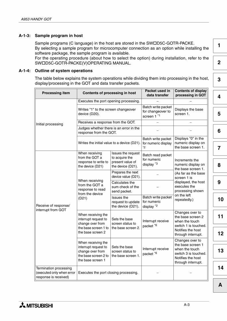
A953 HANDY GOT
1
2
3
4
5
6
7
8
9
10
11
12
13
14
A
A-1-3: Sample program in host
Sample programs (C language) in the host are stored in the SW D5C-GOTR-PACKE.By selecting a sample program for microcomputer connection as an option while installing thesoftware package, the sample program is available.For the operating procedure (about how to select the option) during installation, refer to theSW D5C-GOTR-PACKE(V)OPERATING MANUAL.
A-1-4: Outline of system operations
The table below explains the system operations while dividing them into processing in the host,display/processing in the GOT and data transfer packets.
Processing item Contents of processing in host Packet used in data transfer
Contents of displayprocessing in GOT
Initial processing
Executes the port opening processing. − −
Writes "1" to the screen changeover device (D20).
Batch write packet for changeover to screen 1 *1
Displays the base screen 1.
Receives a response from the GOT. − −Judges whether there is an error in the response from the GOT.
− −
Writes the initial value to a device (D21).Batch write packet for numeric display *2
Displays "0" in the numeric display on the base screen 1.
Receive of response/interrupt from GOT
When receiving from the GOT a response to write to the device (D21)
Issues the request to acquire the present value of the device (D21).
Batch read packet for numeric display *3
Increments the numeric display on the base screen 1.(As far as the base screen 1 is displayed, the host executes the processing shown on the left repeatedly.)
When receiving from the GOT a response to read from the device (D21)
Prepares the next device value (D21).
−
Calculates the sum check of the send packet.
−
Issues the request to update the device (D21).
Batch write packet for numeric display *2
When receiving the interrupt request to change over from the base screen 1 to the base screen 2
Sets the base screen status to the base screen 2.
Interrupt receive packet *6
Changes over to the base screen 2 when the touch switch 1 is touched.Notifies the host through interrupt.
When receiving the interrupt request to change over from the base screen 2 to the base screen 1
Sets the base screen status to the base screen 1.
Interrupt receive packet *6
Changes over to the base screen 1 when the touch switch 3 is touched.Notifies the host through interrupt.
Termination processing (executed only when error response is received)
Executes the port closing processing. − −
A-3
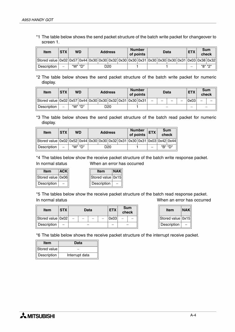
A953 HANDY GOT
*1 The table below shows the send packet structure of the batch write packet for changeover toscreen 1.
*2 The table below shows the send packet structure of the batch write packet for numericdisplay.
*3 The table below shows the send packet structure of the batch read packet for numericdisplay.
*4 The tables below show the receive packet structure of the batch write response packet.In normal status When an error has occurred
*5 The tables below show the receive packet structure of the batch read response packet.In normal status When an error has occurred
*6 The table below shows the receive packet structure of the interrupt receive packet.
Item STX WD AddressNumberof points
Data ETXSum
check
Stored value 0x02 0x57 0x44 0x30 0x30 0x32 0x30 0x30 0x31 0x30 0x30 0x30 0x31 0x03 0x38 0x32
Description − "W" "D" D20 1 1 − "8" "2"
Item STX WD AddressNumberof points
Data ETXSum
check
Stored value 0x02 0x57 0x44 0x30 0x30 0x32 0x31 0x30 0x31 − − − − 0x03 − −Description − "W" "D" D20 1 − − −
Item STX WD AddressNumberof points
ETXSum
check
Stored value 0x02 0x52 0x44 0x30 0x30 0x32 0x31 0x30 0x31 0x03 0x42 0x44
Description − "W" "D" D20 1 − "B" "D"
Item ACK Item NAK
Stored value 0x06 Stored value 0x15
Description − Description −
Item STX Data ETXSum
checkItem NAK
Stored value 0x02 − − − − 0x03 − − Stored value 0x15
Description − − − − Description −
Item Data
Stored value −Description Interrupt data
A-4

1
2
3
4
5
6
7
8
9
10
11
12
13
14
A
1 Introduction
2 Installation Wiring
3 Wiring and Handling of Switches
4 Specifications
5 Connection to Peripheral Equipment
6 CPU Direct Connection
7 Computer Link Connection
8 Connection to PLC by Omron
9 Connection to PLC by Yaskawa Electric
10 Connection to PLC by Allen-Bradley
11 Connection to PLC by Sharp
12 Connection to Microcomputer
13 Connection to PLC by Siemens
14 Diagnostics
A Appendix A
A953 HANDY GOTA953 HANDY GOT
i
A953 HANDY GOT
1 Introduction
2 Installation Wiring
3 Wiring and Handling of Switches
4 Specifications
5 Connection to Peripheral Equipment
6 CPU Direct Connection
7 Computer Link Connection
8 Connection to PLC by Omron
9 Connection to PLC by Yaskawa Electric
10 Connection to PLC by Allen-Bradley
11 Connection to PLC by Sharp
12 Connection to Microcomputer
13 Connection to PLC by Siemens
14 Diagnostics
A Appendix A
ii

HEAD OFFICE: TOKYO BUILDING, 2-7-3 MARUNOUCHI, CHIYODA-KU, TOKYO 100-8310 JAPANHIMEJI WORKS: 840, CHIYODA CHO, HIMEJI, JAPAN
JY992D99801C(MEE)
Effective Sep. 2008Specification are subject to change without notice.
HARDWARE MANUAL
A953 HANDY GOT
MODEL A953H-HW-E
MODEL CODE 09R812
Recommended