9
149
�A750F AUTOMATIC TRANSMISSION
1. General
A newly developed A750F 5-speed automatic transmission [Super ECT (Electronically Controlled Trans-mission)] has been adopted.In addition, the vehicle’s fuel economy and driving performance have been improved by the change intoa 5-speed.
229LC170
� Specification �
Model ’03 Model ’02 Model
Transmission Type A750F A343F
Gear Ratio
1st 3.520 2.804
2nd 2.042 1.531
3rd 1.400 1.000
4th 1.000 0.754
5th 0.716 —
Reverse 3.224 2.393
Fluid CapacityLiters (US qts, Imp. qts) 10.8 (11.4, 9.5) 12.0 (12.7, 10.6)
Fluid Type ATF Type T-IV ATF D-II or equivalent
Dry Weight kg (lb) 79.9 (176.1) 78.6 (173.3)

150
229LC171
C3
Center Planetary Gear
B1C2
B2
F1B3
F2
Rear PlanetaryGear
Front Planetary GearC1
Input Shaft
F3 B4
� Specification �
Model A750F
C1 No.1 Clutch
The No. of Discs
6
C2 No.2 Clutch 5
C3 No.3 Clutch 5
B1 No.1 Brake 3
B2 No.2 Brake 3
B3 No.3 Brake 4
B4 No.4 Brake 8
F1 No.1 One-Way Clutch
The No. of Sprags
24
F2 No.2 One-Way Clutch 25
F3 No.3 One-Way Clutch 26
Front Planetary Gear
The No. of Sun Gear Teeth 40
The No. of Pinion Gear TeethInner 22
Outer 21
The No. of Ring Gear Teeth 91
Center Planetary Gear
The No. of Sun Gear Teeth 31
The No. of Pinion Gear Teeth 23
The No. of Ring Gear Teeth 77
Rear Planetary Gear
The No. of Sun Gear Teeth 25
The No. of Pinion Gear Teeth 19
The No. of Ring Gear Teeth 63

9
151
2. Torque Converter
� A compact, lightweight and high-capacity torque converter has been adopted.
� Compared to the ’02 model, this torque converter offers improved transmission efficiency and a morecompact and lightweight construction by optimizing the fluid passages and the impeller configuration.
� The torque converter clutch supports flex lock-up clutch control, thus improving the fuel economy.
229LC172
� Specification �
ModelA750F A343F
2UZ-FE 2UZ-FE
Type 3-Element, 1-Step, 2-Phase �
Stall Torque Ratio 1.80 �
Dry Weightkg (lb) 15.2 (33.5) 16.2 (35.7)
3. Oil Pump
A new type oil pump is used in which the shape of the teeth in the oil pump have been changed and thecrescent has been discontinued. As a result, the oil pump has been made more compact, and the drivingtorque has been reduced, thus attaining excellent volumetric efficiency during low-speed operation.
165CH10
Crescent
A750F Conventional

152
4. Planetary Gear Unit
Construction
� The 5-speed configuration has been achieved without increasing the number of planetary gears, thuscreating a 5-speed automatic transmission, practically the same as the previous 4-speed automatic trans-mission.
� The front planetary carrier is made of aluminum to reduce the weight.
� A centrifugal fluid pressure canceling mechanism has been adopted in the C1, C2, and C3 clutches thatare applied when shifting from 2nd to 3rd, from 3rd to 4th and from 4th to 5th. For details, refer to page157.
229LC160
Input
Input Shaft
San Gear
Front PlanetaryGear
Rear Planetary Gear
Output
Intermediate Shaft
Center Planetary Gear
C1
C3
B3 B1 B2 B4
F2 F1 F3
C2
Function of Component
Component Function
C1 No.1 Clutch Connects input shaft and intermediate shaft.
C2 No.2 Clutch Connects input shaft and center planetary carrier.
C3 No.3 Clutch Connects input shaft and front sun gear.
B1 No.1 BrakePrevents front planetary carrier from turning either clockwise orcounterclockwise.
B2 No.2 BrakePrevents front and center ring gear from turning either clockwiseor counterclockwise.
B3 No.3 BrakePrevents outer race of F2 from turning either clockwise or counter-clockwise.
B4 No.4 BrakePrevents rear ring gear from turning either clockwise or counter-clockwise.
F1 No.1 One-Way Clutch Prevents front planetary carrier from turning counterclockwise.
F2 No.2 One-Way ClutchWhen B3 is operating, prevents planetary sun gear from turningcounterclockwise.
F3 No.3 One-Way ClutchPrevents center planetary carrier and rear ring gear from turningcounterclockwise.
Planetary GearsThese gears change the route through which driving force is trans-mitted, in accordance with the operation of each clutch and brake,in order to increase or reduce the input and output speed.

9
153
Transmission Power Flow
ShiftLeverPosition
GearSolenoid Valve Clutch Brake
One-wayClutch
S1 S2 SR SL1 SL2 SLU C1 C2 C3 B1 B2 B3 B4 F1 F2 F3
P Park ON ON
R Reverse* ON ON � � � �
N Neutral ON ON
D
1st ON ON � �
2nd ON ON ON � � � �
3rd ON ON � � � �
4th ON ON � � � �
5th ON ON ON � � � �
4
1st ON ON � �
2nd ON ON ON � � � �
3rd ON ON � � � �
4th ON ON � � � �
3
1st ON ON � �
2nd ON ON ON � � � �
3rd* ON � � � �
21st ON ON � �
2nd* ON ON ON � � �
L 1st* ON � �
�: Operation
�: Operate but is not related to power transmission
* : with Engine Brake

154
1st Gear (D, 4, 3 or 2 Position)
229LC174
Input Shaft Sun Gear
Front Planetary Gear
Center Planetary GearRear Planetary Gear
Intermediate ShaftOutput Shaft
C1
C3
C2
B3 B1 B2 B4
F2 F1 F3
2nd Gear (D, 4 or 3 Position)
229LC175
Input Shaft Sun Gear
Front Planetary Gear
Center Planetary GearRear Planetary Gear
Intermediate ShaftOutput Shaft
C1
C3
C2
B3 B1 B2 B4
F2 F1 F3
3rd Gear (D or 4 Position)
229LC176
Input Shaft Sun Gear
Front Planetary Gear
Center Planetary GearRear Planetary Gear
Intermediate ShaftOutput Shaft
C1
C3
C2
B3 B1 B2 B4
F2 F1 F3

9
155
4th Gear (D or 4 Position)
229LC177
Input Shaft Sun Gear
Front Planetary Gear
Center Planetary GearRear Planetary Gear
Intermediate ShaftOutput Shaft
C1
C3
C2
B3 B1 B2 B4
F2 F1 F3
5th Gear (D Position)
229LC178
Input Shaft Sun Gear
Front Planetary Gear
Center Planetary GearRear Planetary Gear
Intermediate ShaftOutput Shaft
C1
C3
C2
B3 B1 B2 B4
F2 F1 F3
1st Gear (L Position)
232CH118
Input Shaft Sun Gear
Front Planetary Gear
Center Planetary GearRear Planetary Gear
Intermediate ShaftOutput Shaft
C1
C3
C2
B3 B1 B2 B4
F2 F1 F3

156
2nd Gear (2nd Position)
232CH119
Input Shaft Sun Gear
Front Planetary Gear
Center Planetary GearRear Planetary Gear
Intermediate ShaftOutput Shaft
C1
C3
C2
B3 B1 B2 B4
F2 F1 F3
3rd Gear (3rd Position)
232CH120
Input Shaft Sun Gear
Front Planetary Gear
Center Planetary GearRear Planetary Gear
Intermediate ShaftOutput Shaft
C1
C3
C2
B3 B1 B2 B4
F2 F1 F3
Reverse Gear (R Position)
229LC169
Input Shaft Sun Gear
Front Planetary Gear
Center Planetary GearRear Planetary Gear
Intermediate ShaftOutput Shaft
C1
C3
C2
B3 B1 B2 B4
F2 F1 F3

9
157CH17
Shaft Side
Centrifugal Fluid PressureApplied to the Chamber A
Fluid pressureapplied to piston −
Centrifugal fluid pressureapplied to chamber B = Target fluid pressure
(original clutch pressure)
Chamber B (Lubrication Fluid)
Centrifugal Fluid PressureApplied to Chamber B
Fluid Pressure Applied to Piston
Clutch
Target Fluid Pressure
Piston FluidPressureChamber
157
Centrifugal Fluid Pressure Canceling Mechanism
There are two reasons for improving the conventional clutch mechanism:
� To prevent the generation of pressure by centrifugal force applied to the fluid in the piston fluid pressurechamber (hereafter referred to as “gchamber A”) when the clutch is released, a check ball is provided.Therefore, before the clutch could be subsequently applied, it took time to fill chamber A.
� During shifting, in addition to the original clutch pressure that is controlled by the valve body, centrifugalpressure acts on the fluid in the chamber A exerting increased pressure depending on RPM.
To address these two needs for improvement, a canceling fluid pressure chamber (hereafter referred toas “chamber B”) has been provided opposite chamber A.
229LC168
Piston C1 Clutch
Chamber A Chamber B
By utilizing the lubrication fluid such as that of the shaft, the same amount of centrifugal force is applied,thus canceling the centrifugal force that is applied to the piston itself. Accordingly, it is not necessaryto discharge the fluid through the use of a check ball, and a highly responsive and smooth shifting character-istic has been achieved.

158
5. Valve Body Unit
General
The valve body consists of the upper and lower valve bodies and 7 solenoid valves.
229LC161
No.1 UpperValve Bode
Solenoid Valve SL2
No.2 UpperValve Bode
Solenoid Valve SLU
Solenoid Valve SR
Lover Valve Body
Solenoid Valve S2
Solenoid Valve S1
Solenoid Valve SL1Solenoid Valve SLT
� No. 2 Upper Valve Body �
229LC163
Coast Brake Relay Valve

9
159
� No. 1 Upper Valve Body �
229LC162
B-1Accumulator
ClutchLock Valve
SolenoidModulator Valve
2-3 Shift Valve1-2 Shift Valve
B1 Apply Control Valve
Brake Control Valve
3-4 Shift Valve
C-3 Check Valve
Lock-upControl Valve
Lock-upRelay Valve
SecondaryRegulator Valve
� Lower Valve Body �
229LC164
Clutch ApplyControl Valve Sequence Valve
AccumulatorControl Valve
ClutchControl Valve
PrimaryRegulator Valve
SLTDamper
160
Solenoid Valve
1) Solenoid Valve S1, S2 and SR
� Solenoid valves S1 and SR use a 3-way solenoid valve.
� Solenoid valve S2 uses a 2-way solenoid valve.
� A filter has been provided at the tip of the solenoid valve to further improve operational reliability.
229LC165
229LC166
Filter
LinePressure
Control Pressure Control Pressure
Drain
Filter
LinePressure
Control Pressure
Solenoid Valve S1 OFF Solenoid Valve S1 ON
Solenoid Valve S2 OFF Solenoid Valve S2 ON
� Function of Solenoid Valve S1, S2 and SR �
Solenoid Valve Type Function
S1 3-way Switches the 2-3 shift valve.
S2 2-way• Switches the 1-2 shift valve.• Switches the 3-4 shift valve.
SR 3-way Switches the clutch apply control valve.
9
161
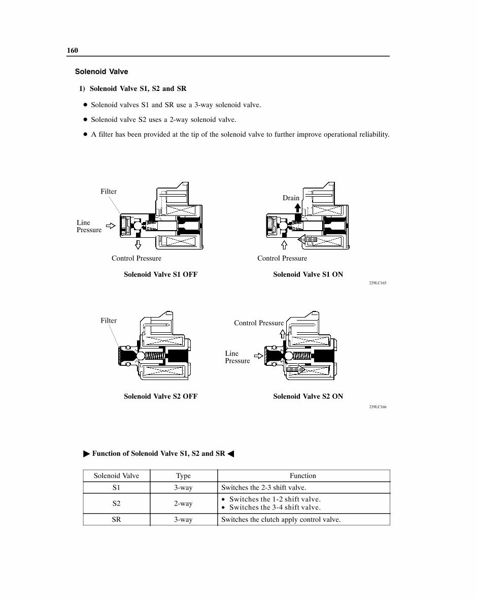
2) Solenoid Valve SL1, SL2, SLT and SLU
� In order to provided a hydraulic pressure that is proportion to current that flows to the solenoid coil,the solenoid valve SL1, SL2, SLT, and SLU linearly controls the line pressure and clutch and brakeengagement pressure based on the signals it receives from the ECM.
� The solenoid valves SL1, SL2, SLT, and SLU have the same basic structure.
229LC181
Spool Valve Solenoid Coil
SleeveSolenoid Valve SLT
HydraulicPressure
Current
HydraulicPressure
Current
Solenoid Valve SL1, SL2 and SLT Solenoid Valve SLU
� Function of Solenoid Valve SL1, SL2, SLT and SLU �
Solenoid Valve Function
SL1• C1 clutch pressure control• Accumulator back pressure control
SL2 B1, B2 and B4 clutch pressure control
SLT• Line pressure control• Accumulator back pressure control
SLU• Lock-up clutch pressure control• Accumulator back pressure control

162
6. Electronic Control System
General
The electronic control system of the ’03 model’s A750F automatic transmission control and the ’02 model’sA343F are compared below.
System Function’03
Model’02
Model
A750F A343F
Clutch PressureControl (See Page 166)
• Controls the pressure that is applied directly to B1 brake andC1 clutch by actuating the linear solenoid valves SL1 andSL2 in accordance with the ECM signals.
• The solenoid valve SLT and SL1 minutely controls theclutch pressure in accordance with the engine output anddriving conditions.
� —
Line PressureOptimal Control(See Page 167)
Actuates the solenoid valve SLT to control the line pressure inaccordance with information from the ECM and the operatingconditions of the transmission.
� �
Engine TorqueControl
Retards the engine ignition timing temporarily to improve shiftfeeling during up or down shifting. � �
Shift TimingControl
The ECM sends current to the solenoid valve S1, S2 and/or SRbased on signals from each sensor and shifts the gear. � —
The ECM sends current to the solenoid valve No.1 and/or No.2based on signals from each sensor and shifts the gear. — �
Flex Lock-upClutch Control(See Page 168)
Controls the solenoid valve SLU, provides an intermediate modebetween the ON/OFF operation of the lock-up clutch, andincrease the operating range of the lock-up clutch to improve fueleconomy.
� —
Lock-up TimingControl
The ECM sends current to the shift solenoid valve SLU based onsignals from each sensor and engages or disengages the lockupclutch.
� —
The ECM sends current to the shift solenoid valve SL based onsignals from each sensor and engages or disengages the lockupclutch.
— �
“N” to “D”Squat Control
When the shift lever is shifted from “N” to “D” position, the gearis temporarily shifted to 2nd and then to 1st to reduce vehiclesquat.
� —
When the shift lever is shifted from “N” to “D” position, the gearis temporarily shifted to 3rd and then to 1st to reduce vehiclesquat.
— �
2nd Start SystemEnabling the vehicle to take off in the 2nd gear and thus make iteasy to take off on snowy, sandy or muddy terrain. � �
AI (artificialIntelligence)-SHIFT (See Page 169)
Based on the signals from various sensors, the ECM determinesthe road conditions and the intention of the driver. Thus, the shiftpattern is automatically regulated to an optimal level, thusimproving drivability.
� —
Diagnosis
When the ECM detects a malfunction, the ECM makes adiagnosis and memorizes the failed section. � �
To increase the speed for processing the signals, the 32-bit CPUof the ECM has been adopted. � �
Fail-safeEven if a malfunction is detected in the sensors or solenoids, theECM effects fail-safe control to prevent the vehicle’s drivabilityfrom being affected significantly.
� �

9
VG
SENSORS
MASS AIR FLOW METER
THROTTLE POSITIONSENSOR
CRANKSHAFT POSITIONSENSOR
ACTUATORS
ENGINE COOLANTTEMP. SENSOR
IGF1
IGT1,4,6,7
FLUID TEMP. SENSOR
INPUT SPEED SENSOR
PATTERN SELECT SWITCH
2nd MODE SWITCH
TRANSFER NEUTRAL DETECTION SWITCH
TRANSFER L4DETECTION SWITCH
PARK/NEUTRALPOSITION SWITCH
TRANSMISSIONCONTROL SWITCH
OUTPUT SPEED SENSOR
STOP LIGHT SWITCH
ESA
IGNITION COIL with IGNITER
Nos. 1, 4, 6 and 7
IGNITION COIL with IGNITER
Nos. 2, 3, 5 and 8
SPARK PLUGS SPARK PLUGS
Nos. 2, 3, 5 and 8 Nos. 1, 4, 6 and 7
SOLENOID VALVE S1
SOLENOID VALVE S2
SOLENOID VALVE SL1
SOLENOID VALVE SL2
SOLENOID VALVE SLT
SOLENOID VALVE SLU
SOLENOID VALVE SR
2nd STARTINDICATOR LIGHT
POWER INDICATOR LIGHT
MALFUNCTIONINDICATOR LAMP
DATA LINK CONNECTOR 3
229LC129
NE
VTA1VTA2
THW
OIL
OIL2
NT
PER
SNWI
TFN
L4
NSW
R, D, 3, 2
4, L
SP2
STP
IGF2
IGT2,3,5,8
S1
S2
SL1
SL2
SLT
SLU
SR
SNWO
PWR
W
SIL, TC
WFSE
163
Construction
The configuration of the electronic control system in the ’03 model’s A750F is as shown in the followingchart.

164
Layout of Component
228LC10
Power Indicator Light 2nd Start Indicator Light
Pattern Select Switch and2nd Mode Switch
Malfunction Indicator Lamp Stop Light SwitchDLC3
Transmission Control Switch
ECM
Output Speed Sensor
Input Speed Sensor
Park/NeutralPosition Switch Solenoid Valve SL1
Solenoid Valve SL1
Solenoid Valve S1
Solenoid Valve S2
Solenoid Valve SR
Solenoid Valve SUL
Solenoid Valve SL2
Fluid Temp. Sensor

9
229LC132
Fluid Temperature Sensor No.1 (OIL)
Fluid Temperature Sensor No.2 (OIL2)
Front
229LC133
Transmission Control Switch
165
Construction and Operation of Main Component
1) Fluid Temperature Sensor No.1 and No.2
� Fluid temperature sensor No.1 (OIL) is usedfor hydraulic pressure control. This sensor isused for revision of clutches and brakes pres-sure to keep smooth shift quality every time.
� Fluid temperature sensor No.2 (OIL2) is usedfor the switching of the shift timing control ofECT when the fluid temperature is high andATF temp. warning light control.
2) Transmission Control Switch
The transmission control switch is installed insideshift lever assembly to detect the shift lever posi-tion (“4th” or “D” and “2nd” or “L”) and to informECM the shift position indicator light in the com-bination meter.
3) Output Speed Sensor and Input Speed Sensor
� A rotor is provided on the output shaft of the transmission, and the output speed sensor on the rightside of the transmission case detects the speed and outputs it to the ECM.
� The input speed sensor detects the input speed of the transmission. The direct clutch drum is usedas the timing rotor for this sensor.
166
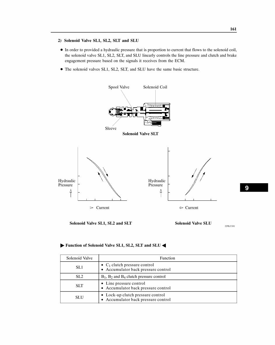
Clutch Pressure Control
1) Clutch to Clutch Pressure Control
This control has been adopted for shifting from the 4th to 5th gear and from the 5th to 4th gear. Actuates solenoid valves SL1 and SL2 in accordance with the signals from the ECM, and guides thisoutput pressure directly to the control valves B1 and C1 in order to regulate the line pressure that actson the B1 brake and C1 clutches. As a result, high response and excellent shift characteristics have been realized.
229LC134
ECM
SL1
Sensor Signal
SL2
C1 Control Valve B1 Control Valve
C1 B1
Line Pressure
• Input Speed Sensor• Output Speed Sensor• Throttle Position
Sensor• Mass Air Flow Meter• Fluid Temp. Sensors• Engine Coolant
Temp. Sensor•••
C1 B1
4th � 5th
5th � 4th
OFF
ON
ON
OFF
2) Clutch Pressure Optimal Control
The ECM monitors the signals from various types of sensor such as the input turbine speed sensor,allowing shift solenoid valves SLT and SL1 to minutely control the clutch pressure in accordance withengine output and driving conditions. As a result, smooth shift characteristics have been realized.
229LC135
Input Shaftrpm
Target rpm ChangeRatio
Practical rpm Change Ratio
Time
EngineCPU
ECM
TransmissionCPU
Input Speed Sensor
Output Speed Sensor
Fluid TempSensorAccumlator
Control Valve SLT, SL1
Clutch/BlockPressure
Solenoid Drive Signal
Output Shaft Torque
Time

9
161ES26
Line Pressure
Primary Regulator
Fluid Pres-sure
Current
Throttle PressurePump
Solenoid Valve SLT
Solenoid Drive Signal
Input Speed SensorFluid TemperatureShift Position
Trans-missionCPU
EngineCPU
Throttle Valve OpeningIntake Air VolumeWater TemperatureEngine rpm
ECM
167
Line Pressure Optimal Control
Through the use of the solenoid valve SLT, the line pressure is optimally controlled in accordance withthe engine toque information, as well as with the internal operating conditions of the toque converterand the transmission. Accordingly, the line pressure can be controlled minutely in accordance with the engine output, travelingcondition, and the ATF temperature, thus realizing smooth shift characteristics and optimizing the work-load in the oil pump.
168
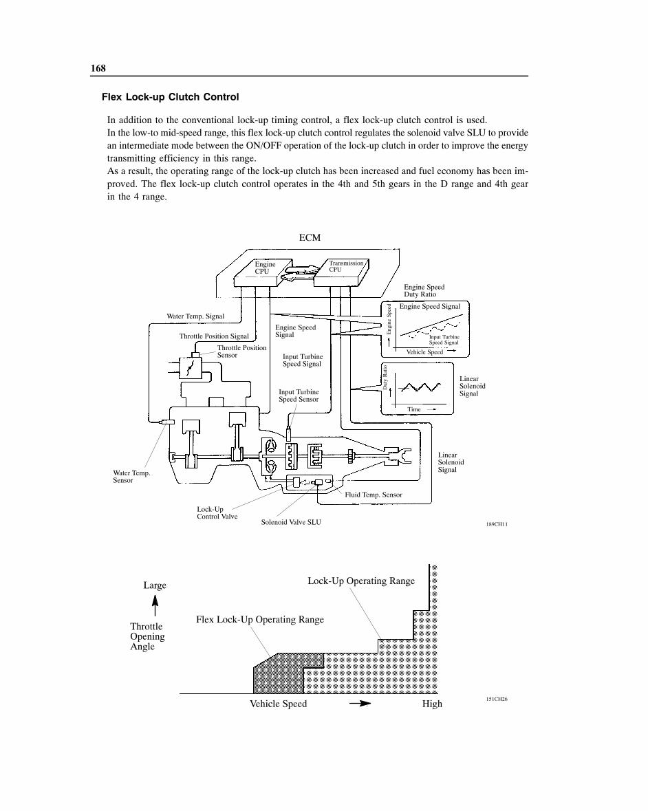
Flex Lock-up Clutch Control
In addition to the conventional lock-up timing control, a flex lock-up clutch control is used.In the low-to mid-speed range, this flex lock-up clutch control regulates the solenoid valve SLU to providean intermediate mode between the ON/OFF operation of the lock-up clutch in order to improve the energytransmitting efficiency in this range.As a result, the operating range of the lock-up clutch has been increased and fuel economy has been im-proved. The flex lock-up clutch control operates in the 4th and 5th gears in the D range and 4th gearin the 4 range.
189CH11
ECM
EngineCPU
TransmissionCPU
Water Temp. Signal
Throttle Position Signal
Throttle PositionSensor
Water Temp.Sensor
Engine SpeedSignal
Input TurbineSpeed Signal
Input TurbineSpeed Sensor
Lock-Up Control Valve
Solenoid Valve SLU
Engine SpeedDuty Ratio
Engine Speed Signal
Input TurbineSpeed Signal
Vehicle Speed
Eng
ine
Spee
d
LinearSolenoidSignal
LinearSolenoidSignal
Time
Dut
y R
atio
Fluid Temp. Sensor
Large
ThrottleOpeningAngle
Lock-Up Operating Range
Flex Lock-Up Operating Range
Vehicle Speed � High151CH26
�

9
169
AI (Artificial Intelligence)- SHIFT Control
1) General
In addition to the switching of the shift pattern through the pattern select switch, the AI- SHIFT controlenables the ECM to estimate the road conditions and the driver’s intention in order to automaticallyswitch the optimal shift pattern. As a result, comfortable ride has been realized at high levels.
229LC182
• ThrottleOpening Angle
• Vehicle Speed
• Engine Speed
• Brake Signal
• VehicleAcceleration
•••••
AI-SHIFT
Road Condition
Uphill/Downhill Driving
Small EstimatingThe Grade
LargeCriterion Acceleration
Actual Acceleration
Driver’s Intention
• AccelerationpedalOperation
• Vehicle Condition
Estimatingthe Driver’sIntention
Basic ShiftPattern Control*
Road Condition Support Control
Driver’sIntentionSupportControl
*: Shift control that is determined by the PWR or 2nd mode that is selected by the pattern select switch,or by the normal mode.

170
2) Road Condition Support Control
Under road condition support control, the ECM determines throttle valve opening angle and the vehiclespeed whether the vehicle is being driven uphill or downhill.To achieve an optimal drive force while driving uphill, this control prevents the transmission from upshift-ing to the 4th or 5th gear. To achieve an optimal engine brake effect while driving downhill, this controlautomatically downshifts the transmission to the 4th or 3rd gear.
229LC183
5th 3rd 4th 3rd 5th 4th5th
(Brake Operating)
5th 4th 3rd 4th 3rd 4th 5thWithout Control
With Control
3) Driver’s Intention Support Control
Estimates the driver’s intention based on the accelerator operation and vehicle condition to switch toa shift pattern that is well-suited to each driver, without the need to operate the shift pattern select switch.

9
Service Tip
171
Diagnosis
� When the ECM detects a malfunction, the ECM makes a diagnosis and memorizes the failed section.Furthermore, the MIL (Malfunction Indicator Lamp) in the combination meter illuminates or blinks toinform the driver.
� At the same time, the DTCs (Diagnosis Trouble Codes) are stored in memory. The DTCs can be readby the SST (09843-18040) between the Tc and CG terminals DLC3 and observing the blinking of thecheck engine warning light, or by connecting a hand-held tester.
The length of time to clear the DTC by the battery terminal disconnection has been changed from theprevious 10 seconds to 1 minute.
Fail Safe
This function minimizes the loss of operability when any abnormality occurs in each sensor or solenoid.
� Fail-Safe Control List �
Malfunction Part Function
Output Speed Sensor(SP2)
During a output speed sensor malfunction, shift control is effected throughthe input speed sensor signal.
Fluid Temp. SensorDuring a fluid temperature sensor No.1 malfunction, 5th upshift and flexlock-up clutch control are prohibited.
Solenoid Valve S1, S2 and SR
The current to the failed solenoid valve is cut off and control is effectedby operating the other solenoid valves with normal operation. Shift control is effected depending on the failed solenoid as described inthe table on the next page.
Solenoid Valve SL1 and SL2
During a solenoid valve SL1 or SL2 malfunction, 5th upshift isprohibited.
Solenoid Valve SLUDuring a solenoid valve SLU malfunction, the current to the solenoidvalve is stopped. Because this stops lock-up control and flex lock-upcontrol, fuel economy decreases.
Solenoid Valve SLT
During a solenoid valve SLT malfunction, the current to the solenoidvalve is stopped. Because this stops line pressure optimal control, the shiftshock increases. However, shifting is effected through normal clutchpressure control.

172
Position
Normal Shift Solenoid Valve S1 MalfunctionShift Solenoid
GearShift Solenoid
GearS1 S2 SR SL1 SL2 S1 S2 SR SL1 SL2
D
ON OFF OFF OFF ON 1st × OFF�ON OFF OFF ON
4th�3rd
ON ON OFF OFF ON 2nd × ON OFF OFF ON 3rdOFF ON OFF OFF ON 3rd × ON OFF OFF ON 3rdOFF OFF OFF OFF ON 4th × OFF OFF OFF ON 4thOFF OFF ON ON OFF 5th × OFF ON ON OFF 5th
4
ON OFF OFF OFF ON 1st × OFF�ON OFF OFF ON
4th�3rd
ON ON OFF OFF ON 2nd × ON OFF OFF ON 3rdOFF ON OFF OFF ON 3rd × ON OFF OFF ON 3rdOFF OFF OFF OFF ON 4th × OFF OFF OFF ON 4th
3
ON OFF OFF OFF ON 1st × OFF�ON OFF OFF
ON�
OFF
3rd�3rd
(E/B)
ON ON OFF OFF ON 2nd × ON OFF OFFON�
OFF
3rd�3rd
(E/B)
OFF ON OFF OFF OFF3rd
(E/B) × ON OFF OFF OFF3rd
(E/B)
2ON OFF OFF OFF ON 1st × OFF OFF OFF ON 1st
ON ON ON OFF OFF2nd
(E/B) × ON ON OFF OFF3rd
(E/B)
L ON OFF OFF OFF OFF1st
(E/B) × OFF OFF OFF OFF1st
(E/B)
Position
Shift Solenoid Valve S2 Malfunction Shift Solenoid Valve SR MalfunctionShift Solenoid
GearShift Solenoid
GearS1 S2 SR SL1 SL2 S1 S2 SR SL1 SL2
D
ON × OFF OFF ON 1st ON OFF × OFF ON 1stON�
OFF × OFF OFF ON1st�4th ON ON × OFF ON 2nd
OFF × OFF OFF ON 4th OFF ON × OFF ON 3rdOFF × OFF OFF ON 4th OFF OFF × OFF ON 4thOFF × ON ON OFF 5th OFF OFF × ON OFF 4th
4
ON × OFF OFF ON 1st ON OFF × OFF ON 1stON�
OFF × OFF OFF ON1st�4th ON ON × OFF ON 2nd
OFF × OFF OFF ON 4th OFF ON × OFF ON 3rdOFF × OFF OFF ON 4th OFF OFF × OFF ON 4th
3
ON × OFF OFF ON 1st ON OFF × OFF ON 1st
ON�
OFF × OFF OFFON�
OFF
1st�3rd
(E/B)ON ON × OFF ON 2nd
OFF × OFF OFF OFF3rd
(E/B) OFF ON × OFFOFF�ON
3rd(E/B)�3rd
2
ON × OFF OFF ON 1st ON OFF × OFF ON 1st
ON�
OFF × ON OFFOFF�ON
2nd(E/B)�4th
ON ON × OFF OFF 2nd
L ON × OFF OFF OFF1st
(E/B) ON OFF × OFF OFF1st
(E/B)
E/B: Engine Brake

9
173
Position
Shift Solenoid Valve S1 and S2 Malfunction Shift Solenoid Valve S1 and SR MalfunctionShift Solenoid
GearShift Solenoid
GearS1 S2 SR SL1 SL2 S1 S2 SR SL1 SL2
D
× × OFF OFF ON 4th × OFF�ON × OFF ON
4th�3rd
× × OFF OFF ON 4th × ON × OFF ON 3rd× × OFF OFF ON 4th × ON × OFF ON 3rd× × OFF OFF ON 4th × OFF × OFF ON 4th
× × ON ON OFF 5th × OFF × ON�
OFFOFF�ON 4th
4
× × OFF OFF ON 4th × OFF�ON × OFF ON
4th�3rd
× × OFF OFF ON 4th × ON × OFF ON 3rd× × OFF OFF ON 4th × ON × OFF ON 3rd× × OFF OFF ON 4th × OFF × OFF ON 4th
3
× × OFF OFFON�
OFF
3rd�3rd
(E/B)× OFF
�ON × OFF ON 3rd
× × OFF OFFON�
OFF
3rd�3rd
(E/B)× ON × OFF ON 3rd
× × OFF OFF OFF3rd
(E/B) × ON × OFFOFF�ON
3rd(E/B)�3rd
2× × OFF OFF ON 1st × OFF × OFF ON 1st
× × ON OFFOFF�ON 4th × ON × OFF OFF 2nd
L × × OFF OFF OFF1st
(E/B) × OFF × OFF OFF1st
(E/B)
Position
Shift Solenoid Valve S2 and SR Malfunction Shift Solenoid Valve S1, S2 and SR MalfunctionShift Solenoid
GearShift Solenoid
GearS1 S2 SR SL1 SL2 S1 S2 SR SL1 SL2
D
ON × × OFF ON 1st × × × OFF ON 4thON�
OFF × × OFF ON1st�4th × × × OFF ON 4th
OFF × × OFF ON 4th × × × OFF ON 4thOFF × × OFF ON 4th × × × OFF ON 4th
OFF × × ON�
OFFOFF�ON 4th × × × ON�
OFFOFF�ON 4th
4
ON × × OFF ON 1st × × × OFF ON 4thON�
OFF × × OFF ON1st�4th × × × OFF ON 4th
OFF × × OFF ON 4th × × × OFF ON 4thOFF × × OFF ON 4th × × × OFF ON 4th
3
ON × × OFF ON 1st × × × OFF ON 3rdON�
OFF × × OFF ON1st�3rd × × × OFF ON 3rd
OFF × × OFFOFF�ON
3rd(E/B)�3rd
× × × OFFOFF�ON
3rd(E/B)�3rd
2
ON × × OFF ON 1st × × × OFF ON 1st
ON × × OFFOFF�ON
1st(E/B)�1st
× × × OFFOFF�ON
1st(E/B)�1st
L ON × × OFF OFF1st
(E/B) × × × OFF OFF1st
(E/B)
E/B: Engine Brake

174
7. Shift Control Mechanism
General
� A gate type shift lever has is used in conjunction with the installation of the 5-speed automatic transmis-sion. With the gate type, the shift lever button and the overdrive switch of the straight type shift leverhave been discontinued. Similar functions are achieved through a single-shift operation (fore-aft andside-to-side).
� The shift lock system consists of the key interlock device and shift lock mechanism.
211CH23229LC136
Shift Lock System
1) General
� A shift lock system with key interlock device and shift lock mechanism, that helps prevent the unin-tended operation of the shift lever has been provided.
� An electrical key interlock device and an electrical shift lock mechanism are used.
229LC137
Stop Light Switch
Ignition Switch
Override Button
Shift Lock Solenoid
Shift Lock ECU

9
229LC138
Lock Pin
Key InterlockSolenoid
175
2) Key Interlock Device
The activation of the key interlock solenoid,mounted on the upper column bracket, moves thelock pin to restrict the movement of the key cylin-der. Therefore, if the shift lever is shifted to anyposition other than “P”, the ignition key cannotbe moved from “ACC” to the “LOCK” position.
3) Shift Lock Mechanism
� The shift lock mechanism prevents the shift lever from being shifted out of the “P” position to anyother position unless the ignition switch is turned ON and the brake pedal is pressed.
� A shift lock override button, which manually overrides the shift lock mechanism, is provided.
� System Diagram �
229LC139
Stop Light Switch
Ignition Switch
Shift LockECU
Shift Lock Solenoid
Recommended


![A960E AUTOMATIC TRANSMISSION · A960E AUTOMATIC TRANSMISSION GENERAL The A960E 6-speed automatic transmission [6 Super ECT (Electronic Controlled Transmission)] is used on the 4GR-FSE](https://img.pdfslide.us/doc/110x75/5e8ff69218b2bd4cae3aae4a/a960e-automatic-transmission-a960e-automatic-transmission-general-the-a960e-6-speed.jpg)