ACT
UA
TORS
A1
A1.62
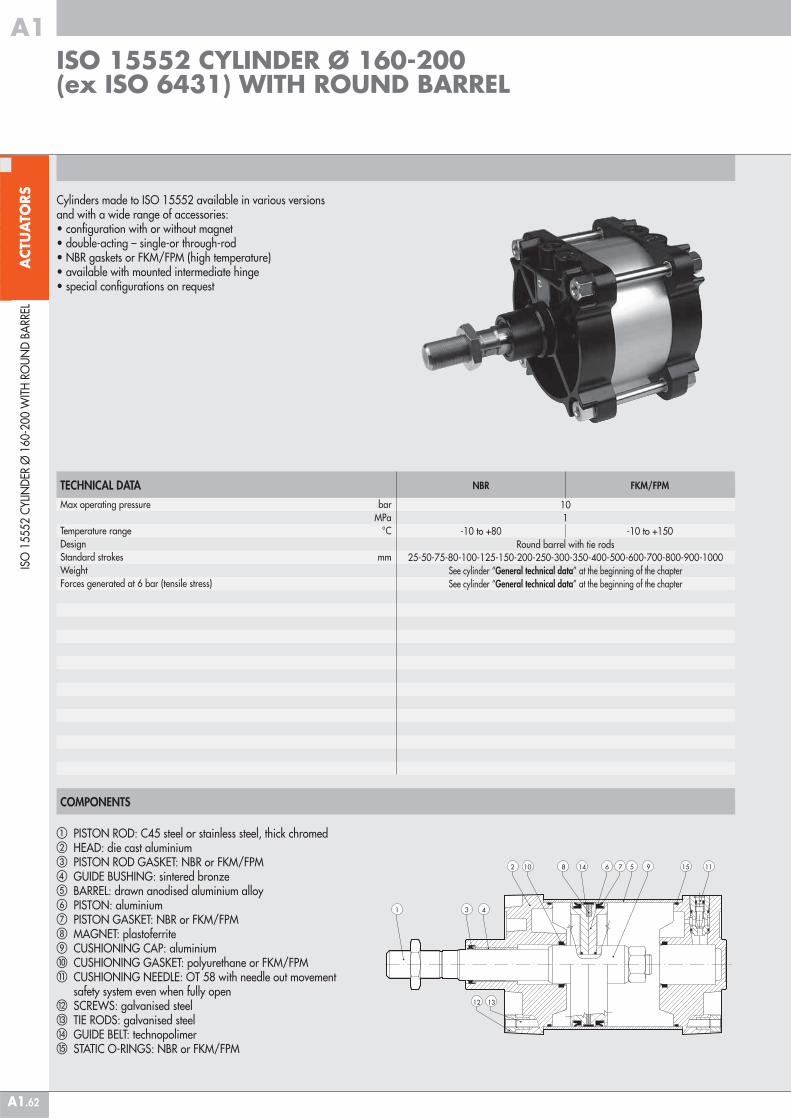
COMPONENTS
� PISTON ROD: C45 steel or stainless steel, thick chromed� HEAD: die cast aluminium� PISTON ROD GASKET: NBR or FKM/FPM� GUIDE BUSHING: sintered bronze� BARREL: drawn anodised aluminium alloy� PISTON: aluminium� PISTON GASKET: NBR or FKM/FPM MAGNET: plastoferrite CUSHIONING CAP: aluminium � CUSHIONING GASKET: polyurethane or FKM/FPM� CUSHIONING NEEDLE: OT 58 with needle out movement safety system even when fully open SCREWS: galvanised steel� TIE RODS: galvanised steel� GUIDE BELT: technopolimer� STATIC O-RINGS: NBR or FKM/FPM
Cylinders made to ISO 15552 available in various versions and with a wide range of accessories:• configuration with or without magnet• double-acting – single-or through-rod• NBR gaskets or FKM/FPM (high temperature)• available with mounted intermediate hinge• special configurations on request
ISO
155
52 C
YLIN
DER
Ø 1
60-2
00 W
ITH
RO
UN
D B
ARR
EL
ISO 15552 CYLINDER Ø 160-200 (ex ISO 6431) WITH ROUND BARREL
TECHNICAL DATAMax operating pressure bar MPaTemperature range °CDesignStandard strokes mmWeight Forces generated at 6 bar (tensile stress)
NBR FKM/FPM
101
-10 to +80 -10 to +150Round barrel with tie rods
25-50-75-80-100-125-150-200-250-300-350-400-500-600-700-800-900-1000See cylinder “General technical data” at the beginning of the chapterSee cylinder “General technical data” at the beginning of the chapter
ACT
UA
TORS
A1
A1.63
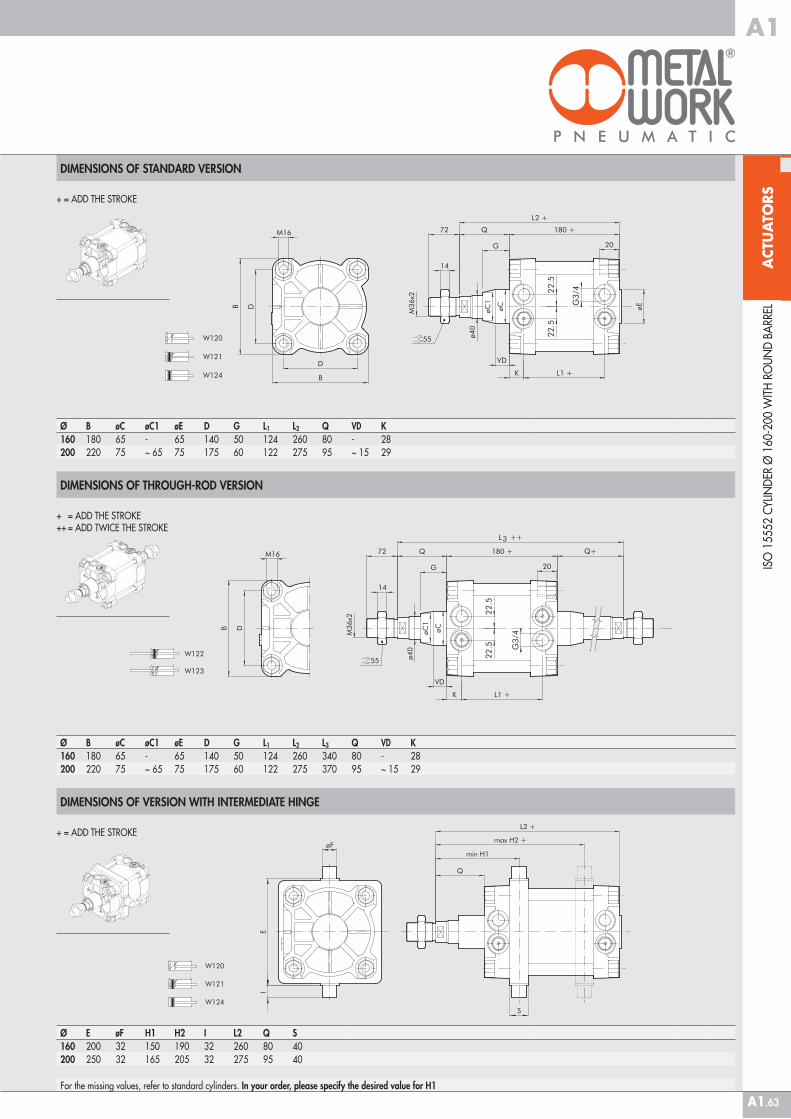
DIMENSIONS OF STANDARD VERSION
Ø E øF H1 H2 I L2 Q S160 200 32 150 190 32 260 80 40200 250 32 165 205 32 275 95 40
For the missing values, refer to standard cylinders. In your order, please specify the desired value for H1
DIMENSIONS OF THROUGH-ROD VERSION
ISO
155
52 C
YLIN
DER
Ø 1
60-2
00 W
ITH
RO
UN
D B
ARR
EL
DIMENSIONS OF VERSION WITH INTERMEDIATE HINGE
+ = ADD THE STROKE
+ = ADD THE STROKE
+ = ADD THE STROKE++ = ADD TWICE THE STROKE
Ø B øC øC1 øE D G L1 L2 L3 Q VD K160 180 65 - 65 140 50 124 260 340 80 - 28200 220 75 ~ 65 75 175 60 122 275 370 95 ~ 15 29
Ø B øC øC1 øE D G L1 L2 Q VD K160 180 65 - 65 140 50 124 260 80 - 28200 220 75 ~ 65 75 175 60 122 275 95 ~ 15 29
ACT
UA
TORS
A1
A1.64
KEY TO CODES FOR ROUND BARREL
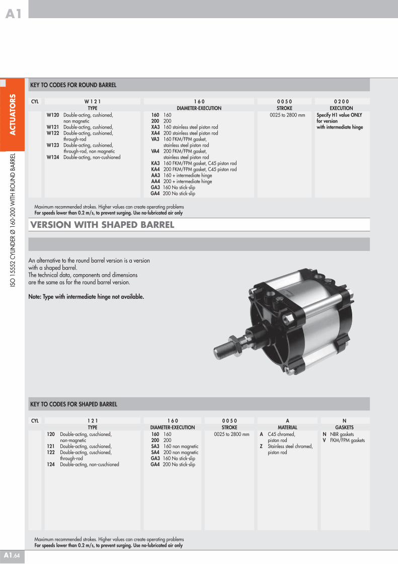
An alternative to the round barrel version is a version with a shaped barrel.The technical data, components and dimensions are the same as for the round barrel version.
Note: Type with intermediate hinge not available.
CYL W 1 2 1 1 6 0 0 0 5 0 0 2 0 0TYPE DIAMETER-EXECUTION STROKE EXECUTION
W120 Double-acting, cushioned, non magneticW121 Double-acting, cushioned,W122 Double-acting, cushioned, through-rodW123 Double-acting, cushioned, through-rod, non magneticW124 Double-acting, non-cushioned
160 160 200 200 XA3 160 stainless steel piston rod XA4 200 stainless steel piston rod VA3 160 FKM/FPM gasket, stainless steel piston rod VA4 200 FKM/FPM gasket, stainless steel piston rod KA3 160 FKM/FPM gasket, C45 piston rod KA4 200 FKM/FPM gasket, C45 piston rod AA3 160 + intermediate hinge AA4 200 + intermediate hinge
GA3 160 No stick-slip GA4 200 No stick-slip
0025 to 2800 mm Specify H1 value ONLY for version with intermediate hinge
Maximum recommended strokes. Higher values can create operating problems For speeds lower than 0.2 m/s, to prevent surging. Use no-lubricated air only
KEY TO CODES FOR SHAPED BARREL
ISO
155
52 C
YLIN
DER
Ø 1
60-2
00 W
ITH
RO
UN
D B
ARR
EL
VERSION WITH SHAPED BARREL
CYL 1 2 1 1 6 0 0 0 5 0 A NTYPE DIAMETER-EXECUTION STROKE MATERIAL GASKETS
120 Double-acting, cuschioned, non-magnetic121 Double-acting, cuschioned,122 Double-acting, cuschioned, through-rod124 Double-acting, non-cuschioned
160 160 200 200 SA3 160 non magnetic SA4 200 non magnetic
GA3 160 No stick-slip GA4 200 No stick-slip
0025 to 2800 mm A C45 chromed, piston rodZ Stainless steel chromed, piston rod
N NBR gasketsV FKM/FPM gaskets
Maximum recommended strokes. Higher values can create operating problems For speeds lower than 0.2 m/s, to prevent surging. Use no-lubricated air only
ACT
UA
TORS
A1
A1.65
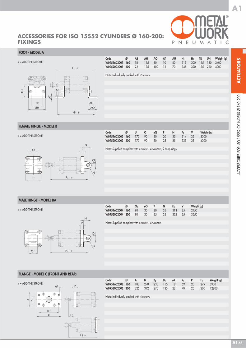
FOOT - MODEL A
FEMALE HINGE - MODEL B
MALE HINGE - MODEL BA
FLANGE - MODEL C (FRONT AND REAR)
ACCESSORIES FOR ISO 15552 CYLINDERS Ø 160-200: FIXINGS
Code Ø AB AH AO AT AU H1 H2 TR UH Weight [g]W0951602001 160 18 115 80 10 60 319 300 115 180 2400W0952002001 200 22 135 100 12 70 345 320 135 220 4000
Note: Individually packed with 2 screws
+ = ADD THE STROKE
+ = ADD THE STROKECode Ø U O øQ P N F3 V Weight [g]W0951602003 160 170 90 30 20 35 314 25 3300W0952002003 200 170 90 30 25 35 335 25 4300
Note: Supplied complete with 4 screws, 4 washers, 2 snap rings
+ = ADD THE STROKECode Ø O1 øO P N F3 V Weight [g]W0951602004 160 90 30 20 35 314 25 2150W0952002004 200 90 30 25 35 335 25 3550
Note: Supplied complete with 4 screws, 4 washers
AC
CES
SORI
ES F
OR
ISO
155
52 C
YLIN
DER
S Ø
160
-200
+ = ADD THE STROKECode Ø A B B2 D1 øK R1 P F1 Weight [g]W0951602002 160 180 270 230 115 18 59 20 279 6900W0952002002 200 225 312 270 135 22 70 25 300 12800
Note: Individually packed with 4 screws
ACT
UA
TORS
A1
A1.66
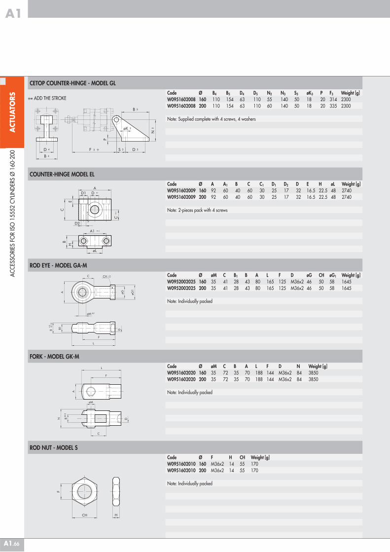
CETOP COUNTER-HINGE - MODEL GL
COUNTER-HINGE MODEL EL
ROD EYE - MODEL GA-M
FORK - MODEL GK-M
ROD NUT - MODEL S
Code Ø B4 B5 D4 D5 N2 N3 S3 øK3 P F3 Weight [g]W0951602008 160 110 154 63 110 55 140 50 18 20 314 2300W0951602008 200 110 154 63 110 60 140 50 18 20 335 2300
Note: Supplied complete with 4 screws, 4 washers
AC
CES
SORI
ES F
OR
ISO
155
52 C
YLIN
DER
S Ø
160
-200
+= ADD THE STROKE
Code Ø A A1 B C C1 D1 D2 D E H øL Weight [g]W0951602009 160 92 60 40 60 30 25 17 32 16.5 22.5 48 2740W0951602009 200 92 60 40 60 30 25 17 32 16.5 22.5 48 2740
Note: 2-pieces pack with 4 screws
Code Ø øM C B1 B A L F D øG CH øG1 Weight [g]W0952002025 160 35 41 28 43 80 165 125 M36x2 46 50 58 1645W0952002025 200 35 41 28 43 80 165 125 M36x2 46 50 58 1645
Note: Individually packed
Code Ø øM C B A L F D N Weight [g]W0951602020 160 35 72 35 70 188 144 M36x2 84 3850W0951602020 200 35 72 35 70 188 144 M36x2 84 3850
Note: Individually packed
Code Ø F H CH Weight [g]W0951602010 160 M36x2 14 55 170W0951602010 200 M36x2 14 55 170
Note: Individually packed
ACT
UA
TORS
A1
A1.67
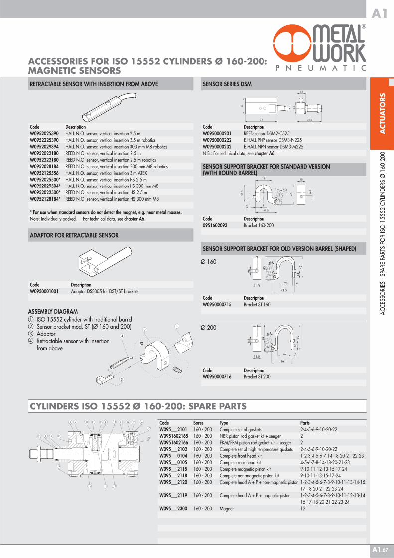
ACCESSORIES FOR ISO 15552 CYLINDERS Ø 160-200: MAGNETIC SENSORS
AC
CES
SORI
ES -
SPA
RE P
ART
S FO
R IS
O 1
5552
CYL
IND
ERS
Ø 1
60-2
00
Code DescriptionW0950000201 REED sensor DSM2-C525W0950000222 E.HALL PNP sensor DSM3-N225W0950000232 E.HALL NPN sensor DSM3-M225N.B.: For technical data, see chapter A6.
Code Description0951602093 Bracket 160-200
Code DescriptionW0950000715 Bracket ST 160
Code DescriptionW0950000716 Bracket ST 200
SENSOR SUPPORT BRACKET FOR STANDARD VERSION (WITH ROUND BARREL)
SENSOR SUPPORT BRACKET FOR OLD VERSION BARREL (SHAPED)
SENSOR SERIES DSM
Ø 160
Ø 200
CYLINDERS ISO 15552 Ø 160-200: SPARE PARTS
Code DescriptionW0950001001 Adaptor DSS005 for DST/ST brackets
ASSEMBLY DIAGRAM� ISO 15552 cylinder with traditional barrel� Sensor bracket mod. ST (Ø 160 and 200)� Adaptor� Retractable sensor with insertion from above
RETRACTABLE SENSOR WITH INSERTION FROM ABOVE
ADAPTOR FOR RETRACTABLE SENSOR
Code DescriptionW0952025390 HALL N.O. sensor, vertical insertion 2.5 mW0952225390 HALL N.O. sensor, vertical insertion 2.5 m roboticsW0952029394 HALL N.O. sensor, vertical insertion 300 mm M8 roboticsW0952022180 REED N.O. sensor, vertical insertion 2.5 mW0952222180 REED N.O. sensor, vertical insertion 2.5 m roboticsW0952028184 REED N.O. sensor, vertical insertion 300 mm M8 roboticsW0952125556 HALL N.O. sensor, vertical insertion 2 m ATEXW0952025500* HALL N.O. sensor, vertical insertion HS 2.5 mW0952029504* HALL N.O. sensor, vertical insertion HS 300 mm M8W0952022500* REED N.O. sensor, vertical insertion HS 2.5 mW0952128184* REED N.O. sensor, vertical insertion HS 300 mm M8
* For use when standard sensors do not detect the magnet, e.g. near metal masses. Note: Individually packed. For technical data, see chapter A6.
Code Bores Type PartsW095___2101 160 - 200 Complete set of gaskets 2-4-5-6-9-10-20-22W0951602165 160 - 200 NBR piston rod gasket kit + seeger 2W0951602166 160 - 200 FKM/FPM piston rod gasket kit + seeger 2W095___2102 160 - 200 Complete set of high temperature gaskets 2-4-5-6-9-10-20-22W095___0104 160 - 200 Complete front head kit 1-2-3-4-5-6-7-14-18-20-21-22-23W095___0105 160 - 200 Complete rear head kit 4-5-6-7-8-14-18-20-21-23W095___2115 160 - 200 Complete magnetic piston kit 9-10-11-12-13-15-17-24W095___2118 160 - 200 Complete non-magnetic piston kit 9-10-11-13-15-17-24W095___2120 160 - 200 Complete head A + P + non-magnetic piston 1-2-3-4-5-6-7-8-9-10-11-13-14-15
17-18-20-21-22-23-24W095___2119 160 - 200 Complete head A + P + magnetic piston 1-2-3-4-5-6-7-8-9-10-11-12-13-14
15-17-18-20-21-22-23-24W095___2300 160 - 200 Magnet 12
ACT
UA
TORS
A1
A1.68
ISO
155
52 C
YLIN
DER
Ø 2
50-3
20
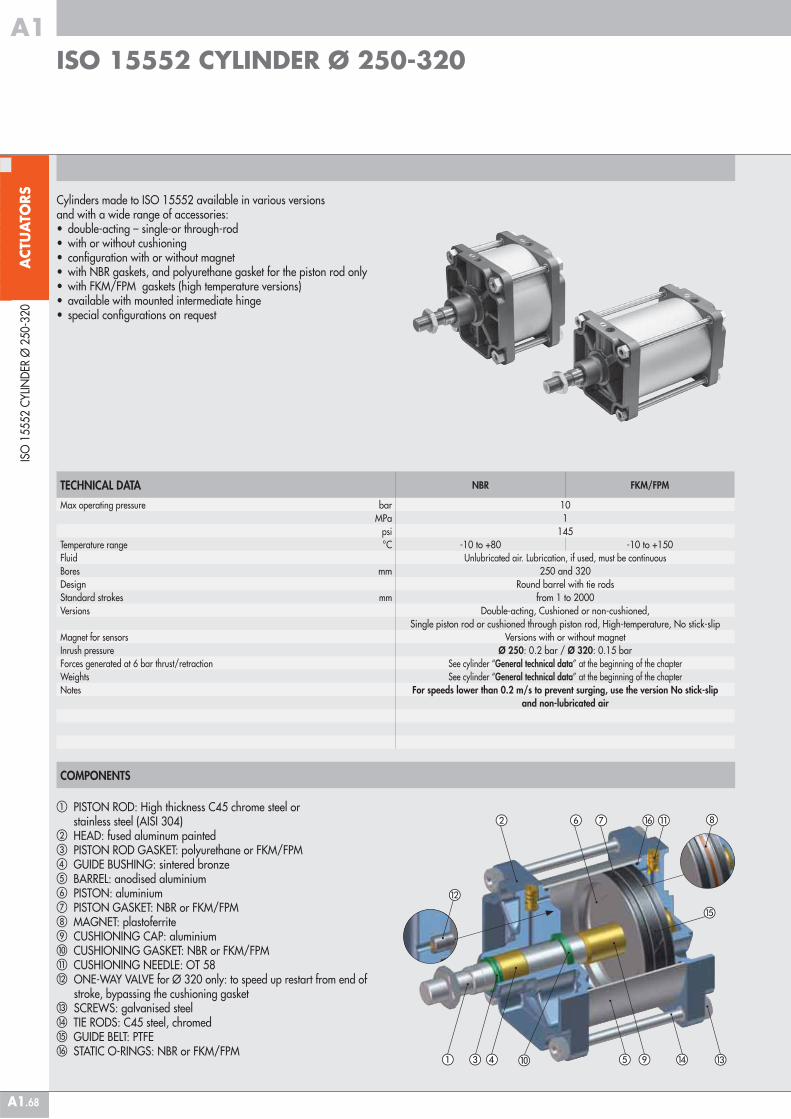
ISO 15552 CYLINDER Ø 250-320
COMPONENTS
� PISTON ROD: High thickness C45 chrome steel or stainless steel (AISI 304) � HEAD: fused aluminum painted� PISTON ROD GASKET: polyurethane or FKM/FPM � GUIDE BUSHING: sintered bronze � BARREL: anodised aluminium� PISTON: aluminium� PISTON GASKET: NBR or FKM/FPM MAGNET: plastoferrite CUSHIONING CAP: aluminium � CUSHIONING GASKET: NBR or FKM/FPM� CUSHIONING NEEDLE: OT 58 ONE-WAY VALVE for Ø 320 only: to speed up restart from end of stroke, bypassing the cushioning gasket � SCREWS: galvanised steel� TIE RODS: C45 steel, chromed� GUIDE BELT: PTFE� STATIC O-RINGS: NBR or FKM/FPM
Cylinders made to ISO 15552 available in various versions and with a wide range of accessories:• double-acting – single-or through-rod• with or without cushioning• configuration with or without magnet• with NBR gaskets, and polyurethane gasket for the piston rod only • with FKM/FPM gaskets (high temperature versions)• available with mounted intermediate hinge• special configurations on request
TECHNICAL DATA NBR FKM/FPM
Max operating pressure bar 10MPa 1
psi 145Temperature range °C -10 to +80 -10 to +150Fluid Unlubricated air. Lubrication, if used, must be continuousBores mm 250 and 320Design Round barrel with tie rodsStandard strokes mm from 1 to 2000Versions Double-acting, Cushioned or non-cushioned,
Single piston rod or cushioned through piston rod, High-temperature, No stick-slipMagnet for sensors Versions with or without magnetInrush pressure Ø 250: 0.2 bar / Ø 320: 0.15 barForces generated at 6 bar thrust/retraction See cylinder “General technical data” at the beginning of the chapterWeights See cylinder “General technical data” at the beginning of the chapterNotes For speeds lower than 0.2 m/s to prevent surging, use the version No stick-slip
and non-lubricated air
�� �
���
�
� ��
�
��
ACT
UA
TORS
A1
A1.69
ISO
155
52 C
YLIN
DER
Ø 2
50-3
20
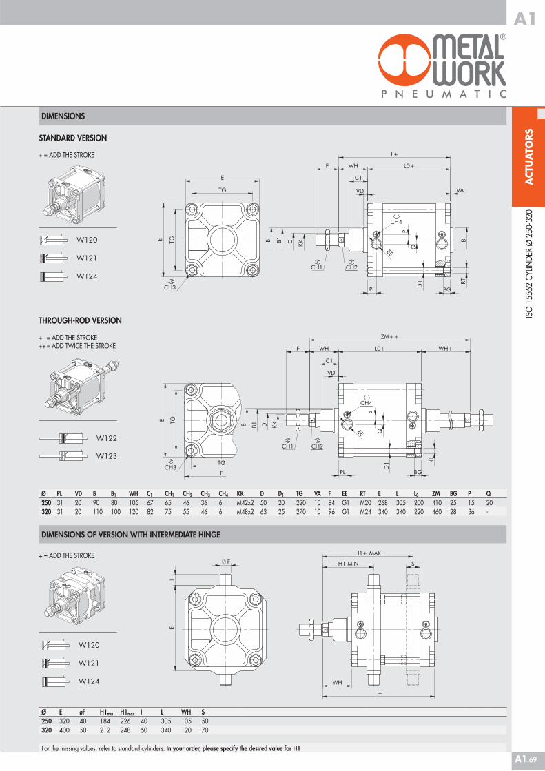
DIMENSIONS
Ø E øF H1min H1max I L WH S250 320 40 184 226 40 305 105 50320 400 50 212 248 50 340 120 70
For the missing values, refer to standard cylinders. In your order, please specify the desired value for H1
DIMENSIONS OF VERSION WITH INTERMEDIATE HINGE
+ = ADD THE STROKE
STANDARD VERSION
+ = ADD THE STROKE
THROUGH-ROD VERSION
+ = ADD THE STROKE++ = ADD TWICE THE STROKE
Ø PL VD B B1 WH C1 CH1 CH2 CH3 CH4 KK D D1 TG VA F EE RT E L L0 ZM BG P Q250 31 20 90 80 105 67 65 46 36 6 M42x2 50 20 220 10 84 G1 M20 268 305 200 410 25 15 20320 31 20 110 100 120 82 75 55 46 6 M48x2 63 25 270 10 96 G1 M24 340 340 220 460 28 36 -
ACT
UA
TORS
A1
A1.70
ISO
155
52 C
YLIN
DER
Ø 2
50-3
20
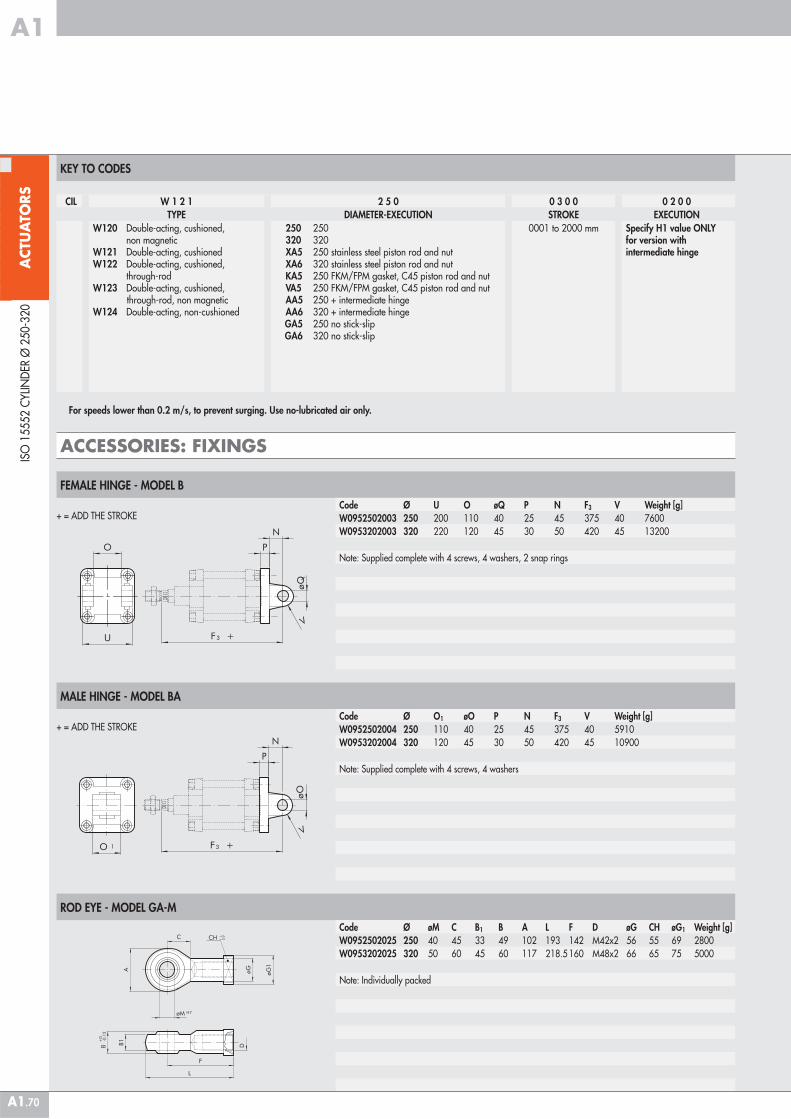
KEY TO CODES
CIL W 1 2 1 2 5 0 0 3 0 0 0 2 0 0TYPE DIAMETER-EXECUTION STROKE EXECUTION
W120 Double-acting, cushioned, non magneticW121 Double-acting, cushionedW122 Double-acting, cushioned, through-rodW123 Double-acting, cushioned, through-rod, non magneticW124 Double-acting, non-cushioned
250 250 320 320 XA5 250 stainless steel piston rod and nut XA6 320 stainless steel piston rod and nut KA5 250 FKM/FPM gasket, C45 piston rod and nut VA5 250 FKM/FPM gasket, C45 piston rod and nut AA5 250 + intermediate hinge AA6 320 + intermediate hinge
GA5 250 no stick-slipGA6 320 no stick-slip
0001 to 2000 mm Specify H1 value ONLYfor version with intermediate hinge
For speeds lower than 0.2 m/s, to prevent surging. Use no-lubricated air only.
FEMALE HINGE - MODEL B
+ = ADD THE STROKECode Ø U O øQ P N F3 V Weight [g]W0952502003 250 200 110 40 25 45 375 40 7600W0953202003 320 220 120 45 30 50 420 45 13200
Note: Supplied complete with 4 screws, 4 washers, 2 snap rings
MALE HINGE - MODEL BA
+ = ADD THE STROKECode Ø O1 øO P N F3 V Weight [g]W0952502004 250 110 40 25 45 375 40 5910W0953202004 320 120 45 30 50 420 45 10900
Note: Supplied complete with 4 screws, 4 washers
ACCESSORIES: FIXINGS
ROD EYE - MODEL GA-M
Code Ø øM C B1 B A L F D øG CH øG1 Weight [g]W0952502025 250 40 45 33 49 102 193 142 M42x2 56 55 69 2800W0953202025 320 50 60 45 60 117 218.5 160 M48x2 66 65 75 5000
Note: Individually packed
ACT
UA
TORS
A1
A1.71
ISO
155
52 C
YLIN
DER
Ø 2
50-3
20
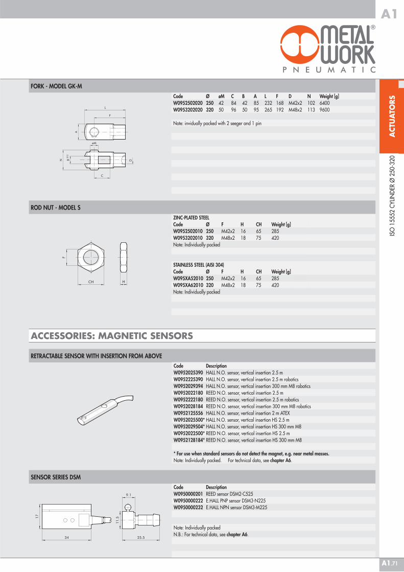
ROD NUT - MODEL S
ZINC-PLATED STEELCode Ø F H CH Weight [g]W0952502010 250 M42x2 16 65 285W0953202010 320 M48x2 18 75 420Note: Individually packed
STAINLESS STEEL (AISI 304)Code Ø F H CH Weight [g]W095XA52010 250 M42x2 16 65 285W095XA62010 320 M48x2 18 75 420Note: Individually packed
ACCESSORIES: MAGNETIC SENSORS
RETRACTABLE SENSOR WITH INSERTION FROM ABOVE
Code DescriptionW0950000201 REED sensor DSM2-C525W0950000222 E.HALL PNP sensor DSM3-N225W0950000232 E.HALL NPN sensor DSM3-M225
Note: Individually packedN.B.: For technical data, see chapter A6.
SENSOR SERIES DSM
Code DescriptionW0952025390 HALL N.O. sensor, vertical insertion 2.5 mW0952225390 HALL N.O. sensor, vertical insertion 2.5 m roboticsW0952029394 HALL N.O. sensor, vertical insertion 300 mm M8 roboticsW0952022180 REED N.O. sensor, vertical insertion 2.5 mW0952222180 REED N.O. sensor, vertical insertion 2.5 m roboticsW0952028184 REED N.O. sensor, vertical insertion 300 mm M8 roboticsW0952125556 HALL N.O. sensor, vertical insertion 2 m ATEXW0952025500* HALL N.O. sensor, vertical insertion HS 2.5 mW0952029504* HALL N.O. sensor, vertical insertion HS 300 mm M8W0952022500* REED N.O. sensor, vertical insertion HS 2.5 mW0952128184* REED N.O. sensor, vertical insertion HS 300 mm M8
* For use when standard sensors do not detect the magnet, e.g. near metal masses. Note: Individually packed. For technical data, see chapter A6.
FORK - MODEL GK-M
Code Ø øM C B A L F D N Weight [g]W0952502020 250 42 84 42 85 232 168 M42x2 102 6400W0953202020 320 50 96 50 95 265 192 M48x2 113 9600
Note: invidually packed with 2 seeger and 1 pin
ACT
UA
TORS
A1
A1.72
ISO
155
52 C
YLIN
DER
Ø 2
50-3
20
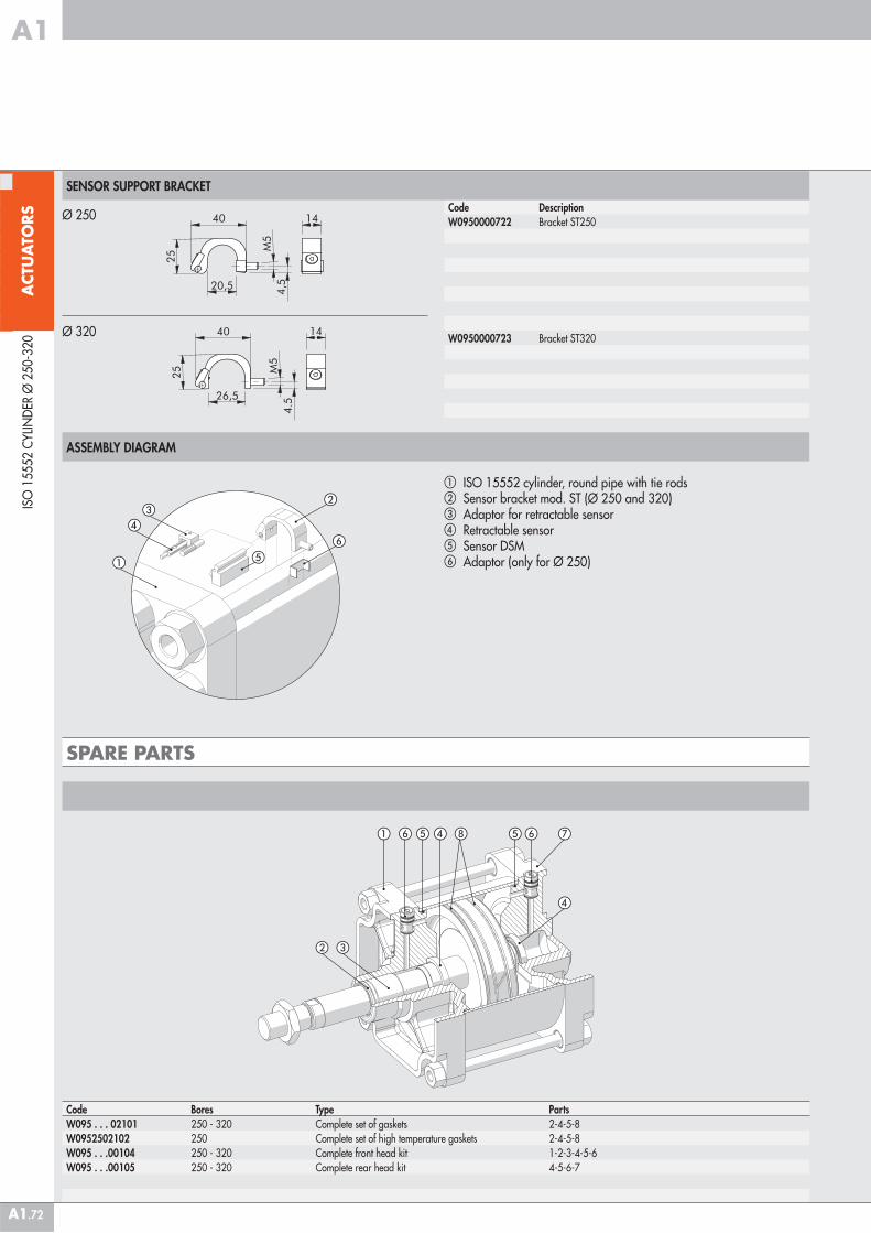
Code Bores Type PartsW095 . . . 02101 250 - 320 Complete set of gaskets 2-4-5-8W0952502102 250 Complete set of high temperature gaskets 2-4-5-8W095 . . .00104 250 - 320 Complete front head kit 1-2-3-4-5-6W095 . . .00105 250 - 320 Complete rear head kit 4-5-6-7
Code DescriptionW0950000722 Bracket ST250
W0950000723 Bracket ST320
SENSOR SUPPORT BRACKET
Ø 250
Ø 320
� ISO 15552 cylinder, round pipe with tie rods� Sensor bracket mod. ST (Ø 250 and 320)� Adaptor for retractable sensor� Retractable sensor� Sensor DSM� Adaptor (only for Ø 250)
ASSEMBLY DIAGRAM
SPARE PARTS
� � �� �
�
�
� �
�
�
�
�
��
�
Recommended