A UML Profile for Enterprise Distributed Object Computing
Joint Final Submission
Part I
Version 0.29
18 June 2001
OMG Document Number: ad/2001-06-09
Submitted by:
CBOP Data Access Technologies DSTC EDS Fujitsu IBM Iona Technologies Open-IT Sun Microsystems Unisys
Supported by:
Hitachi SINTEF NetAccount

ad/2001-06-09 - Part I
ii A UML Profile for Enterprise Distributed Object Computing 2001-06-18
©Copyright 2000, CBOP, Data Access Technologies, DSTC, EDS, Fujitsu, IBM, Iona Technologies, Open-IT, Sun Microsystems, Unisys.
CBOP, Data Access Technologies, DSTC, EDS, Fujitsu, IBM, Iona Technologies, Open-IT, Sun Microsystems, Unisys hereby grant to the Object Management Group, Inc. a nonexclusive, royalty-free, paid up, worldwide license to copy and distribute this document and to modify this document and distribute copies of the modified version.
Each of the copyright holders listed above has agreed that no person shall be deemed to have infringed the copyright in the included material of any such copyright holder by reason of having used the specification set forth herein or having conformed any computer software to the specification.
NOTICE
The information contained in this document is subject to change without notice.
The material in this document details an Object Management Group specification in accordance with the license and notices set forth on this page. This document does not represent a commitment to implement any portion of this specification in any companies' products.
WHILE THE INFORMATION IN THIS PUBLICATION IS BELIEVED TO BE ACCURATE, THE OBJECT MANAGEMENT GROUP, CBOP, DATA ACCESS TECHNOLOGIES, DSTC, EDS, FUJITSU, IBM, IONA TECHNOLOGIES, OPEN-IT, SUN MICROSYSTEMS AND UNISYS MAKE NO WARRANTY OF ANY KIND WITH REGARDS TO THIS MATERIAL INCLUDING, BUT NOT LIMITED TO, THE IMPLIED WARRANTIES OF MERCHANTABILITY AND FITNESS FOR A PARTICULAR PURPOSE. The aforementioned copyright holders shall not be liable for errors contained herein or for incidental or consequential damages in connection with the furnishing, performance, or use of this material.
The copyright holders listed above acknowledge that the Object Management Group (acting itself or through its designees) is and shall at all times be the sole entity that may authorize developers, suppliers and sellers of computer software to use certification marks, trademarks or other special designations to indicate compliance with these materials. This document contains information which is protected by copyright. All Rights Reserved. No part of this work covered by copyright herein may be reproduced or used in any form or by any means—graphic, electronic or mechanical, including photocopying, recording, taping, or information storage and retrieval systems—without permission of the copyright owner.
RESTRICTED RIGHTS LEGEND. Use, duplication, or disclosure by government is subject to restrictions as set forth in subdivision (c) (1) (ii) of the Right in Technical Data and Computer Software Clause at DFARS 252.227.7013.
OMG and Object Management are registered trademarks of the Object Management Group, Inc. Object Request Broker, OMG IDL, ORB CORBA, CORBAfacilities, and CORBAservices are trademarks of the Object Management Group.
The UML logo is a trademark of Rational Software Corp.
ISSUE REPORTING
All OMG specifications are subject to continuous review and improvement. As part of this process we encourage readers to report any ambiguities, inconsistencies, or inaccuracies they may find by sending email to [email protected]. Please reference precise page and section numbers, and state the specification name, version number, and revision date as they appear on the front page, along with a brief description of the problem. You will not receive any reply, but your report will be referred to the OMG Revision Task Force responsible for the maintenance of the specification. If you wish to be consulted or informed during the resolution of the submitted issue, indicate this in your email. Please note that issues appear eventually in the issues database, which is publicly accessible.
ad/2001-06-09 - Part I
2001-06-18 A UML Profile for Enterprise Distributed Object Computing iii
Contents
Figures ................................................................................................................................................................... iv
Tables ...................................................................................................................................................................vii
Chapter 1: Formal Response to the RFP ................................................................................................................. 1 1. Introduction .............................................................................................................................................. 3 2. Proof of Concept .................................................................................................................................... 10 3. Response to RFP Requirements.............................................................................................................. 13 4. Conformance Issues................................................................................................................................ 17 5. Changes or extensions required to adopted OMG specifications ........................................................... 18 6. Proof of Concept mappings .................................................................................................................... 18
Chapter 2: EDOC Profile – Rationale and Application ........................................................................................ 19 1. Vision ..................................................................................................................................................... 20 2. The EDOC Profile Elements .................................................................................................................. 22 3. Application of the EDOC Profile Elements............................................................................................ 30
Chapter 3 The Enterprise Collaboration Architecture........................................................................................... 40 1. ECA Design Rationale............................................................................................................................ 43 2. The Component Collaboration Architecture........................................................................................... 50 3. The Entities Profile............................................................................................................................... 188 4. The Events Profile ................................................................................................................................ 219 5. The Business Processes Profile ............................................................................................................ 262 6. The Relationships Profile ..................................................................................................................... 320
Chapter 4 The Patterns Profile............................................................................................................................ 345 1. Rationale............................................................................................................................................... 346 2. Patterns Metamodel .............................................................................................................................. 354 3. UML Profile ......................................................................................................................................... 359
Chapter 5 Technology Specific Models.............................................................................................................. 365 1. The EJB and Java Metamodels............................................................................................................. 367 2. Flow Composition Model ..................................................................................................................... 400
Chapter 6 UML Profile for MOF........................................................................................................................ 415 1. Introduction .......................................................................................................................................... 418 2. UML-to-MOF Mapping Table ............................................................................................................. 419 3. Mapping Details ................................................................................................................................... 420 4. Guidelines............................................................................................................................................. 433
Glossary .............................................................................................................................................................. 435
References........................................................................................................................................................... 437
ad/2001-06-09 - Part I
iv A UML Profile for Enterprise Distributed Object Computing 2001-06-18
Figures
Figure 1: UML for EDOC Submission Structure.....................................................................................................5 Figure 2: An Example of BFOP Pattern Hierarchy...............................................................................................28 Figure 3: EDOC Profile elements related to the ISO RM ODP viewpoints..........................................................32 Figure 4: ProcessComponent Composition at multiple levels................................................................................36 Figure 5: EDOC framework vision ........................................................................................................................48 Figure 6: Structure and dependencies of the CCA Metamodel ..............................................................................56 Figure 7: CCA Major elements ..............................................................................................................................58 Figure 8: Structural Specification Metamodel .......................................................................................................59 Figure 9: Choreography Metamodel ......................................................................................................................76 Figure 10: Composition metamodel .......................................................................................................................87 Figure 11: Document Metamodel ..........................................................................................................................97 Figure 12: Model Management Metamodel.........................................................................................................107 Figure 13: ProcessComponent specification notation ..........................................................................................110 Figure 14: ProcessComponent specification notation (expanded ProtocolPorts).................................................111 Figure 15: Composite Component notation (without internal ComponentUsages) ..............................................112 Figure 16: Composite Component notation .........................................................................................................112 Figure 17: CommunityProcess notation ...............................................................................................................113 Figure 18: UML«metamodel» and CCA «profile»Packages ..............................................................................116 Figure 19: Stereotypes in the UML Profile for CCA ...........................................................................................117 Figure 20: Stereotypes for Structural Specification .............................................................................................118 Figure 21: Stereotypes for Choreography ............................................................................................................133 Figure 22: Stereotypes for Composition ..............................................................................................................140 Figure 23: Stereotypes for DocumentModel ........................................................................................................147 Figure 24: Top Level Collaboration Diagram......................................................................................................173 Figure 25: Class diagram for protocol structure...................................................................................................174 Figure 26: Choreography of a Protocol................................................................................................................176 Figure 27: Class Diagram for Component Structure ............................................................................................178 Figure 28: Class Diagram for Interface................................................................................................................180 Figure 29: Using Interfaces..................................................................................................................................180 Figure 30: Process Components with multiple ports............................................................................................181 Figure 31: Choreography of a Process Component..............................................................................................182 Figure 32: Process Component Composition.......................................................................................................183 Figure 33: Model Management............................................................................................................................186 Figure 34: Community Process and Protocol.......................................................................................................187 Figure 35 Composition in CCA notation .............................................................................................................187 Figure 36: Entity Model in the Information Viewpoint........................................................................................196 Figure 37: Entity Model in the Composition Viewpoint ......................................................................................197 Figure 38: Entity Metamodel ...............................................................................................................................198 Figure 39:, Entity Model Extensions to UML......................................................................................................210 Figure 40: Event Based Business Modeling ........................................................................................................221 Figure 41: Intra Process Event Notification.........................................................................................................226 Figure 42: Cross Process Event Notification .......................................................................................................227 Figure 43: Delegation ..........................................................................................................................................228 Figure 44: Business Process View of metamodel ................................................................................................231 Figure 45: Entity View of metamodel ..................................................................................................................232 Figure 46: Complete Metamodel for Event Modeling .........................................................................................233 Figure 47: Metamodel of event notification view ................................................................................................234 Figure 48: Diagram of Event Package .................................................................................................................240 Figure 49: Business process/entity/event diagram ...............................................................................................260 Figure 50: Composition of Process ModelElements. ...........................................................................................263
ad/2001-06-09 - Part I
2001-06-18 A UML Profile for Enterprise Distributed Object Computing v
Figure 51: Inputs and Outputs of Process ModelElements. .................................................................................264 Figure 52: Diagram of the Roles aspect of the Process Model. ...........................................................................266 Figure 53: A labeled CompoundTask Diagram ...................................................................................................268 Figure 54: State Machine describing execution of Activities and CompoundTasks. ...........................................270 Figure 55: Illegal DataFlows crossing Task boundaries. .....................................................................................278 Figure 56: Example Protocol describing the behavior of ProcessMultiPorts.......................................................279 Figure 58: An ExceptionGroup that is handled by and Activity ..........................................................................282 Figure 59: An unhandled ExceptionGroup that will be propagated if it is enabled at runtime. ...........................282 Figure 60: BusinessProcess «profile» Package....................................................................................................288 Figure 60: Activity with synchronous and asynchronous InputGroups, an OutputGroup and an ExceptionGroup.310 Figure 61: Activity that is involves creation of a Composition of nested Activities, etc......................................310 Figure 62: A CompoundTask showing its composed Activities. .........................................................................311 Figure 63: Timeout Pattern ..................................................................................................................................312 Figure 64: Timer pattern notation ........................................................................................................................312 Figure 65: Templated activity supporting a terminate message. ..........................................................................313 Figure 66: Preconditions on an InputGroup and an OutputGroup. ......................................................................313 Figure 67: An equivalent model to that of Figure 66, using condition tasks........................................................314 Figure 68: Post-conditions on OutputGroups of Activities. .................................................................................314 Figure 69: An equivalent model to that of Figure 68, using condition tasks........................................................315 Figure 70: Simple Loop Pattern...........................................................................................................................315 Figure 71: Simple Loop Notation ........................................................................................................................316 Figure 72: While Loop Pattern ............................................................................................................................316 Figure 73: Repeat/Until Loop Pattern..................................................................................................................316 Figure 74: While Loop Notation..........................................................................................................................317 Figure 75: Repeat-Until Notation ........................................................................................................................317 Figure 76: For Loop Pattern.................................................................................................................................317 Figure 77: Pattern for a multi-task .......................................................................................................................318 Figure 79: Combined MOF model of Process .....................................................................................................319 Figure 79: UML Extensions Representing Multiple Viewpoints .........................................................................323 Figure 80: Multiple Subtyping Hierarchies for the Same Supertype....................................................................324 Figure 81: Class Diagram of the Virtual Metamodel ...........................................................................................326 Figure 82: Notation for Shared, Non-Binary Aggregation...................................................................................328 Figure 83: Notation for Composite, Non-Binary Aggregation.............................................................................329 Figure 84: Notation for Reference .......................................................................................................................335 Figure 85: Notation for ReferenceForCreate .......................................................................................................336 Figure 86: Association End Names Resulting from Decomposing a Non-Binary Aggregation (General Case) ..339 Figure 87: Association End Names Resulting from Decomposing a Non-Binary Aggregation (Special Case) ..340 Figure 88: Fragment of Reconciliation Specification ..........................................................................................342 Figure 89: <<Reference>> Stereotype Used To Show Structure of Specification...............................................343 Figure 90: An Example of BFOP Pattern Hierarchy...........................................................................................347 Figure 91: Defining the “Composition” Pattern..................................................................................................349 Figure 92: Applying the “Composition” Pattern.................................................................................................349 Figure 93: Unfolded “Composition” Pattern.......................................................................................................350 Figure 94: The format of Simple Pattern ............................................................................................................350 Figure 95: The Format of Pattern Inheritance.....................................................................................................351 Figure 96: The Format of Pattern Composition ..................................................................................................352 Figure 97: The Summary of Pattern Formats .....................................................................................................352 Figure 98: An Example of BFOP Structure and Unfolding ................................................................................353 Figure 99: Metamodel for Business Pattern Package..........................................................................................354 Figure 100: Patterns <<profile>> Package ..........................................................................................................359 Figure 101: Notation for Business Pattern Package............................................................................................361 Figure 102: Notation for Business Pattern Binding ............................................................................................363 Figure 103: Class Contents ..................................................................................................................................368 Figure 104: Polymorphism...................................................................................................................................374 Figure 105: JavaType...........................................................................................................................................374 Figure 106: TypeDescriptor.................................................................................................................................376 Figure 107: Data Types........................................................................................................................................377
ad/2001-06-09 - Part I
vi A UML Profile for Enterprise Distributed Object Computing 2001-06-18
Figure 108: Names...............................................................................................................................................377 Figure 109: Main .................................................................................................................................................378 Figure 110: EJB ...................................................................................................................................................383 Figure 111: Entity Bean .......................................................................................................................................389 Figure 112: Assembly ..........................................................................................................................................390 Figure 113: EJB Implementation .........................................................................................................................393 Figure 114: References to Resources...................................................................................................................395 Figure 115: Data Types........................................................................................................................................397 Figure 116: FCMCore Package, Main Diagram .................................................................................................401 Figure 117: FCMCore Package, FCMComponent Diagram...............................................................................402 Figure 118: FCM Package, FCMConnections Diagram .....................................................................................406 Figure 119: FCM Package, FCMNodes Diagram...............................................................................................407 Figure 120: Transfer/Refund Money FCMComposition.....................................................................................410 Figure 121: FCMSource and FCMSink for the Transfer Money FCMFlow.......................................................411 Figure 122: FCMControlLink and FCMDataLink from TransferSource to CheckAccount................................411 Figure 123: FCMCommand with associated FCMConnections and FCMComponent .......................................412
ad/2001-06-09 - Part I
2001-06-18 A UML Profile for Enterprise Distributed Object Computing vii
Tables
Table 1: Stereotypes for Structural Specification (UML notation: Class Diagram).............................................114 Table 2: TaggedValues for Structural Specification ............................................................................................114 Table 3: Stereotypes for Choreography (UML notation: Statechart Diagram) ....................................................115 Table 4: TaggedValues for Choreography...........................................................................................................115 Table 5: Stereotypes for Composition (UML notation: Collaboration Diagram at specification level)...............115 Table 6: TaggedValues for Composition .............................................................................................................115 Table 7: Stereotypes for DocumentModel (UML notation: Class Diagram) ......................................................116 Table 8: TaggedValues for DocumentModel.......................................................................................................116 Table 9: Summary of stereotypes for a Community Process................................................................................174 Table 10: Summary of stereotypes for a Protocol................................................................................................175 Table 11: Summary of tagged values for a Protocol ............................................................................................176 Table 12: Stereotypes for an Activity Diagram or Choreography........................................................................177 Table 13: Tagged Values for a Choreography .....................................................................................................177 Table 14: Stereotypes for a Process Component Class Diagram .........................................................................179 Table 15: tagged values for a Process Component Class Diagram ......................................................................179 Table 16: Elements of an Interface ......................................................................................................................180 Table 17: Connections .........................................................................................................................................184 Table 18: Stereotypes for a Process Component Collaboration...........................................................................184 Table 19 Element Mappings ................................................................................................................................209 Table 20 Mapping Events Concepts to Profile Elements.....................................................................................248 Table 21 BusinessProcess «profile» Package : Stereotypes.................................................................................287 Table 22 BusinessProcess «profile» Package : TaggedValues ............................................................................288 Table 23 «ProcessFlowPort» Tagged Values ......................................................................................................294 Table 24«ProcessRole» Tagged Values...............................................................................................................302 Table 25: CompoundTask own ProcessMultiPort subtypes.................................................................................308 Table 26: ProcessMultiPort Subtypes own ProcessFlowPorts.............................................................................308 Table 27: Activities and ProcessPortConnectors owned by CompoundTasks and BusinessProcesses................308 Table 28: CompoundTask owns Activity and DataFlow .....................................................................................309 Table 29: Activity uses CompoundTask ..............................................................................................................309 Table 30: Represents in CompoundTask and BusinessProcess ...........................................................................309 Table 31 Element Mappings ................................................................................................................................359 Table 32: Mapping Java Metamodel concepts to profile elements ......................................................................399 Table 33: Mapping Flow Composition Model concepts to profile elements ......................................................409 Table 34 Glossary of Terms.................................................................................................................................435

ad/2001-06-09 - Part I
2001-06-18 A UML Profile for Enterprise Distributed Object Computing – Chapter 1 1
Chapter 1: Formal Response to the RFP
Table of Contents
1. Introduction....................................................................................................................................................... 3 1.1 The Joint UML for EDOC Profile Submission......................................................................................... 3 1.2 Co-submitting Companies ........................................................................................................................ 3 1.3 Status of this document............................................................................................................................. 3 1.4 Guide to the Submission........................................................................................................................... 4
1.4.1 Overall structure of the submission................................................................................................. 4 1.4.2 Structure of Chapter 1 ..................................................................................................................... 6
1.5 Missing Items ........................................................................................................................................... 6 1.6 Submission contact points ........................................................................................................................ 7
1.6.1 CBOP.............................................................................................................................................. 7 1.6.2 Data Access Technologies .............................................................................................................. 7 1.6.3 DSTC .............................................................................................................................................. 7 1.6.4 EDS................................................................................................................................................. 8 1.6.5 Fujitsu ............................................................................................................................................. 8 1.6.6 IBM................................................................................................................................................. 8 1.6.7 Iona ................................................................................................................................................. 8 1.6.8 Open-IT........................................................................................................................................... 8 1.6.9 SINTEF........................................................................................................................................... 8 1.6.10 Sun Microsystems ........................................................................................................................... 8 1.6.11 Unisys ............................................................................................................................................. 9
2. Proof of Concept ............................................................................................................................................. 10 2.1 CBOP ..................................................................................................................................................... 10 2.2 Data Access Technologies...................................................................................................................... 10 2.3 DSTC...................................................................................................................................................... 10 2.4 EDS ........................................................................................................................................................ 11 2.5 Fujitsu..................................................................................................................................................... 11 2.6 IBM ........................................................................................................................................................ 11 2.7 Iona......................................................................................................................................................... 11 2.8 Open-IT and SINTEF............................................................................................................................. 11 2.9 Sun Microsystems................................................................................................................................... 12 2.10 Unisys ..................................................................................................................................................... 12
3. Response to RFP Requirements ...................................................................................................................... 13 3.1 General Mandatory Requirements .......................................................................................................... 13 3.2 Specific Mandatory Requirements.......................................................................................................... 13
3.2.1 Component Modeling.................................................................................................................... 13 3.2.2 Modeling of Business Process, Entity, Rule, and Event Objects .................................................. 14 3.2.3 Specification of Business Process Objects.................................................................................... 14 3.2.4 Specification of Relationships....................................................................................................... 14 3.2.5 Meta-Object Facility Alignment.................................................................................................... 15
ad/2001-06-09 - Part I
2 A UML Profile for Enterprise Distributed Object Computing – Chapter 1 2001-06-18
3.2.6 Proof of Concept of Profile ........................................................................................................... 15 3.2.7 Proof of Concept of Mappability .................................................................................................. 15
3.3 Optional Requirements ........................................................................................................................... 15 3.4 Subset Integrity....................................................................................................................................... 16 3.5 Simplification of and Aid to the Development Process .......................................................................... 16 3.6 Tool support ........................................................................................................................................... 16 3.7 Alignment with Action Semantics for UML........................................................................................... 17
4. Conformance Issues ........................................................................................................................................ 17 4.1 Summary of optional versus mandatory interfaces ................................................................................. 17 4.2 Proposed compliance points ................................................................................................................... 17
5. Changes or extensions required to adopted OMG specifications .................................................................... 18
6. Proof of Concept mappings............................................................................................................................. 18
ad/2001-06-09 - Part I
2001-06-18 A UML Profile for Enterprise Distributed Object Computing – Chapter 1 3
1. Introduction
1.1 The Joint UML for EDOC Profile Submission
The Joint UML for EDOC Profile Submission is a specification for a UML Profile for Enterprise Distributed Object Computing (EDOC), prepared by the submitting team listed below in response to the OA&DTF RFP 6 (UML Profile for EDOC, OMG Document ad/99-03-10).
1.2 Co-submitting Companies
This submission is prepared by the following companies:
• CBOP • Data Access Technologies • DSTC • EDS • Fujitsu • IBM • Iona Technologies • Open-IT • Sun Microsystems • Unisys
Supporting companies are:
• Hitachi • Netaccount • SINTEF
1.3 Status of this document
This document is the final iteration in a submission process that commenced in October 1999, when initial submissions were made. At that time it was hoped that a single joint submission team could be formed to prepare a single Final submission. Regrettably, because the requirements of the RFP are very wide and complex, it was not possible to achieve that aim in a single iteration, and in February 2001 four revised submissions were presented. Subsequently the companies making three of those submissions agreed to collaborate on a single, integrated submission, and this is the result. The fourth submission made in February 2001, known as the Distributed Component Profile (DCP), was not progressed further; it was decided that this was more appropriate as a response for a forthcoming normative mapping RFP.
ad/2001-06-09 - Part I
4 A UML Profile for Enterprise Distributed Object Computing – Chapter 1 2001-06-18
1.4 Guide to the Submission
1.4.1 Overall structure of the submission
This submission is divided into two parts as follows:
• Part I (this Part) is the normative specification of the UML Profile for EDOC;
• Part II contains a number of annexes which provide a set of non-normative mappings and a set of worked examples explaining the uses of the various parts of the Profile.
1.4.1.1 Part I
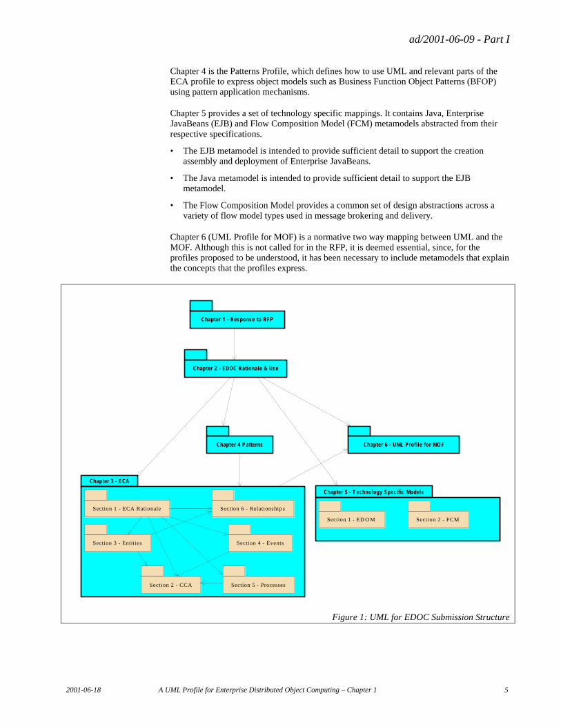
Part I contains six chapters as illustrated in Figure 1 below:
Chapter 1 is the formal response to the submission as required by the RFP.
Chapter 2 explains the overall rationale for the submission approach, and provides a framework for system specification using the EDOC Profile. It provides a detailed rationale for the modeling choices made and describes how the various elements in the submission may be used, within the viewpoint oriented framework of the Reference Model of Open Distributed Processing (RM-ODP), to model all phases of a software system’s lifecycle, including, but not limited to:
• the analysis phase when the roles played by the system’s components in the business it supports are defined and related to the business requirements;
• the design and implementation phases, when detailed specifications for the system’s components are developed;
• the maintenance phase, when, after implementation, the system’s structure or behavior is modified and tuned to meet the changing business environment in which it will work.
Chapter 3 is the Enterprise Collaboration Architecture (ECA) and contains the detailed profile specifications for platform/ technology independent modeling elements of the profile, specifically:
• the Component Collaboration Architecture (CCA) which details how the UML concepts of classes, collaborations and activity graphs can be used to model, at varying and mixed levels of granularity, the structure and behavior of the components that comprise a system;
• the Entities profile, which describes a set of UML extensions that may be used to model entity objects that are representations of concepts in the application problem domain and define them as composable componentsthe Entities profile, which describes a set of UML extensions that may be used to model entity objects;
• the Events profile, which describes a set of UML extensions that may be used on their own, or in combination with the other EDOC elements, to model event driven systems;
• the Business Processes profile, which specializes the CCA, and describes a set of UML extensions that may be used on their own, or in combination with the other EDOC elements, to model workflow-style business processes in the context of the components and entities that model the business;
• the Relationships profile, which describes the extensions to the UML core facilities to meet the need for rigorous relationship specification in general and in business modeling and software modeling in particular.
ad/2001-06-09 - Part I
2001-06-18 A UML Profile for Enterprise Distributed Object Computing – Chapter 1 5
Chapter 4 is the Patterns Profile, which defines how to use UML and relevant parts of the ECA profile to express object models such as Business Function Object Patterns (BFOP) using pattern application mechanisms.
Chapter 5 provides a set of technology specific mappings. It contains Java, Enterprise JavaBeans (EJB) and Flow Composition Model (FCM) metamodels abstracted from their respective specifications.
• The EJB metamodel is intended to provide sufficient detail to support the creation assembly and deployment of Enterprise JavaBeans.
• The Java metamodel is intended to provide sufficient detail to support the EJB metamodel.
• The Flow Composition Model provides a common set of design abstractions across a variety of flow model types used in message brokering and delivery.
Chapter 6 (UML Profile for MOF) is a normative two way mapping between UML and the MOF. Although this is not called for in the RFP, it is deemed essential, since, for the profiles proposed to be understood, it has been necessary to include metamodels that explain the concepts that the profiles express.
Chapter 1 - Response to RFP
Chapter 2 - EDOC Rationale & Use
Chapter 3 - ECA
Chapter 4 P atterns
Chapter 5 - T echnology Specific Models
Chapter 6 - UML Profile for MO F
Section 1 - ECA Rationale
Section 2 - CCA
Section 3 - Entities Section 4 - Events
Section 5 - Processes
Section 6 - Relationship s
Section 1 - ED O M Section 2 - FCM
Figure 1: UML for EDOC Submission Structure
ad/2001-06-09 - Part I
6 A UML Profile for Enterprise Distributed Object Computing – Chapter 1 2001-06-18
1.4.1.2 Part II
Part II of this submission, (ad/2001/06/10), to be issued shortly after this main document, will contain a variety of supporting non-normative information. The exact set of contents has yet to be finalized, but it is hoped to include the following:
• Procurement, Buyer/Seller example
• Meeting Room example
• Hospital example
• Examples of Patterns
• UML Profile for EJB
• EDOC Technology Mapping to EJB
• UML Profile for CCM
• EDOC Technology Mapping to CCM, CORBA
• EDOC Technology Mapping to FCM
• EDOC Technology Mapping to Web Services
• XMI and DTD data files for the metamodels in the EJB/Java/FCM profiles
1.4.2 Structure of Chapter 1
Section 1 provides contact information and a guide to this submission.
Section 2 is the proof of concept statement.
Section 3 explains how this submission satisfies the mandatory requirements of the RFP.
Section 4 summarizes the rationale for the approach taken in this submission (which is described in detail in Part II).
Section 5 provides a statement of Conformance Points for this specification.
Section 6 discusses changes to OMG adopted standards.
A Glossary and a List of References are provided at the end of this Part.
1.5 Missing Items
As explained in 1.4.1.2, the non-normative Annexes containing supporting material will be published shortly.
ad/2001-06-09 - Part I
2001-06-18 A UML Profile for Enterprise Distributed Object Computing – Chapter 1 7
1.6 Submission contact points
1.6.1 CBOP
Akira Tanaka Hitachi, Ltd., Software Division, Enterprise Business Planning, Product Planning Dept., 5030 Totsuka-cho, Totsuka-ku, Yokohama 244-8555, Japan e-mail: [email protected] phone: +81(45)862-8735 fax:+81(45)865-9020 Hajime Horiuchi Tokyo International University 1-13-1 Matoba-kita, Kawagoe-shi, Saitama 350-1102, Japan Phone: +81-492-32-1111 Email:[email protected] Marika Iizuka Technologic Arts Inc. Cosmos Hongo Bld. 9F, 4-1-4 Hongo, Bunkyo-ku, Tokyo 113-0033, Japan Phone: +81-3-5803-2788 Email: [email protected] Masaharu Obayashi Kanrikogaku Ltd. Meguro Suda Bldg., 3-9-1 Meguro, Meguro-ku, Tokyo 153-0063, Japan Phone: +81-3-3716-6300 Email: [email protected] Yoshihide Nagase Technologic Arts Inc. Cosmos Hongo Bld. 9F, 4-1-4 Hongo, Bunkyo-ku, Tokyo 113-0033, Japan Phone: +81-3-5803-2788 Email: [email protected]
1.6.2 Data Access Technologies
Cory B. Casanave and Antonio Carrasco-Valero 14000 SW 119 Av., Miami, FL 33186, USA Phone: +1 305 238 0012 Email: [email protected] , [email protected]
1.6.3 DSTC
Mr. Keith Duddy, CRC for Enterprise Distributed Systems Technology (DSTC) University of Queensland Brisbane 4072 Australia Phone: +61 7 3365 4310 Fax: +61 7 3365 4311 Email:[email protected], [email protected] WWW: www.dstc.edu.au
ad/2001-06-09 - Part I
8 A UML Profile for Enterprise Distributed Object Computing – Chapter 1 2001-06-18
1.6.4 EDS
Fred Cummins EDS 5555 New King St., MS 402, Troy, MI 48098, USA Phone: (248) 696-2016 Email: [email protected]
1.6.5 Fujitsu
Mr Hiroshi Miyazaki Fujitsu Limited 1-9-3, Nakase Mihama-ku, Chiba-shi, Chiba 261-8588, Japan Phone: +81 43 299 3531 ext 4669 e-mail: <[email protected]>
1.6.6 IBM
Stephen A. Brodsky, Ph.D. International Business Machines Corporation 555 Bailey Ave., J8RA/F320 San Jose, CA 95141 Phone: +1 408 463 5659 E-mail: [email protected]
1.6.7 Iona
David Frankel Iona Technologies 10 North Church Street, West Chester, Pa 19380, USA Phone: 610 429 1553 Email: [email protected]
1.6.8 Open-IT
Mr Sandy Tyndale-Biscoe Open-IT Ltd Cedarcroft, Sunny Way, Bosham, CHICHESTER, West Sussex, PO18 8HQ, U.K. Phone: +44 (0)1243 57 22 23 e-mail: <[email protected]>
1.6.9 SINTEF
Dr. Arne J. Berre SINTEF Telecom and Informatics Forskningsveien 1, Blindern, 0314 Oslo, Norway Phone: +47 22 06 74 52 e-mail: [email protected]
1.6.10 Sun Microsystems
Karsten Riemer,

ad/2001-06-09 - Part I
2001-06-18 A UML Profile for Enterprise Distributed Object Computing – Chapter 1 9
b2b Architect, XML technology Center, Sun Microsystems, Inc., Burlington, MA 01803, USA Phone 781-442-2679 e-mail [email protected]
1.6.11 Unisys
Sridhar Iyengar Unisys Corporation 25725 Jeronimo Rd. Mission Viejo, CA 92691 Phone: +1 949 380 5692 E-mail: [email protected]
ad/2001-06-09 - Part I
10 A UML Profile for Enterprise Distributed Object Computing – Chapter 1 2001-06-18
2. Proof of Concept
This submission is a practical approach to the need for specifying EDOC systems, based on the following real world experience of the companies concerned:
2.1 CBOP
CBOP is a consortium in Japan, promoting the reuse and the sharing of business domain models and software components. The submission of the pattern mechanism to the UML profile for EDOC RFP was based on the CBOP standards that are focused on the normalization of business object patterns for modeling. Current work of CBOP is, inter alia, concerned with the development of UML tools that enable the application of patterns in object modeling with UML. The EDOC standard will be taken in to account in these tools as well as the CBOP standards.
2.2 Data Access Technologies
The CCA profile (Chapter 3 Section 2) is based on product development done by Data Access Technologies under a cooperative agreement with the National Institute of Technologies - Advanced Technology Program. The basis for CCA has been proven in two related works - one as a distributed user interface toolkit for Enterprise Java Beans and more recently as the basis for "Component X Studio" which provides drag-and-drop assembly of server-side application components. Component-X® Studio is in the final stages of development in anticipation of release as a product. Portions of this same model have also been incorporated into ebXml for it's specification schema, giving CCA an XML based technology mapping. Finally, portions of CCA and the related entity model derive from standards, development and consulting work done in relation to the "Business Object Component Architecture" which, while never standardized has proven to be a solid foundation for modeling and implementing a systems information viewpoint. In all cases of the above works, model based development has been used throughout the lifecycle, from design to deployment - proving the sufficiency of the base models to drive execution.
2.3 DSTC
DSTC has used its dMOF product to develop a MOF respository and Human Usable Textual Notation I/O tools which support modeling of Business Processes conforming to the metamodel in Chapter 3, Section 6 (Business Processes Profile). Significant Business Process models have been created using these generated tools, and mapped using XSLT into XML workflow process definitions, which execute on the DSTC's Breeze workflow engine. dMOF is a commercial product installed at many customer sites world-wide, and Breeze is in development and is currently being beta-tested by four DSTC partner organizations.
In addition the dMOF tool has been used to validate the MOF conformance of all the meta-models in Chapter 3. XMI documents containing these meta-models will be submitted as separate conveniece documents.
ad/2001-06-09 - Part I
2001-06-18 A UML Profile for Enterprise Distributed Object Computing – Chapter 1 11
2.4 EDS
EDS developed the Enterprise Business Object Facility (EBOF) product in conjunction with work on the Business Object Facility specification. This product serves as a proof of concept for important aspects of this submission. It incorporated UML models as the basis for generating executable, distributed, CORBA applications. This involved consideration of transactions, persistence, management of relationships, operations on extents, performance optimization and many other factors. This product was sold to a major software vendor.
2.5 Fujitsu
This submission is based in part upon Fujitsu's system analysis and design methodology, "Application Architecture/Business Rule Modeling". The methodology is built into Fujitsu's product, "Application Architecture / Business Rule Modeler - AA/BRMODELER", which has been used for the development of many mission critical business systems. Although applied mainly to the development of COBOL applications, the methodology includes object-oriented characteristics. In this submission, the elements of the methodology and its related product are represented as UML elements and extensions. In the methodology, the specification of business rules is of special concern. The business rules are separated in types and attributed to objects corresponding to the types. These rules are represented in a formal grammar, and they are compiled into executable programs by using AA/BRMODELER. AA/BRMODELER has sold approximately 5000 sets in Japan since it was developed in 1994. It has been applied to approximately 300 projects, some of scale greater than 7,000 person-months.
2.6 IBM
IBM has extensive experience in enterprise architectures, Java, Enterprise Java Beans, CORBA, UML, MOF, and metadata. The WebSphere, MQ, and VisualAge product lines provide sophisticated analysis, design, deployment, and execution functionality embodying all of the key representative technologies.
2.7 Iona
The Relationships Profile is based on many years of modeling experience in industry and in the development of related products and standards. It uses ISO's General Relationship Model and the work of Haim Kilov and James Ross in their book "Information Modeling", which is based on long-term modeling experience in areas such as telecommunications, finance, insurance, document management, and business process change.
The Process Profile incorporates Iona experience modeling enterprise processes with customers from use case descriptions, business models, and other IT system requirements information. It is also based on experience developing process definition and management products for environments ranging from concurrent engineering to document processing.
2.8 Open-IT and SINTEF
The profile incorporates results and experience from the UML profile and associated lexical language that was developed in the European Union funded OBOE project. As part of this project supporting tools were developed and the technology was applied at a user site . A full description of the project is available at [7].
ad/2001-06-09 - Part I
12 A UML Profile for Enterprise Distributed Object Computing – Chapter 1 2001-06-18
The ODP concepts have been applied for the development of the OMG Finance domain General Ledgers specification in the COMPASS project, and a mapping framework for Microsoft COM has been developed by Netaccount (formerly Economica). More information on this is available at [6].
The ODP concepts have also been applied in the domain of geographic information systems. The DISGIS project has demonstrated the usefulness of the separation of concerns in terms of the 5 viewpoints defined by the RM-ODP, and developed an interoperability framework based on this (See [5]). The use of the ODP viewpoints have also been found useful in the context of geographic information system standardization in ISO/TC211 (See [8]) and the Open Geodata Consortium (See [9]).
The enterprise specification concepts have been derived from work for the UK Ministry of Defence and Eurocontrol together with participation in the development of the ODP – Enterprise Language standard [4].
2.9 Sun Microsystems
Sun Microsystems’ internal IT group has successfully implemented large scale Enterprise Integration using a conceptual meta-model close to that defined in the Events profile (Chapter 3 Section 4), covering business process, entity, and event architecture. While this has not been using UML, the work modeled the enterprise and the interaction between system components based on an enterprise business object/event information model. Business objects and events have been modeled in a Sun IT internal language, SDDL, a self describing data language, the syntax of which is equivalent to the modeling framework proposed here.
This implementation is successful, and by a rough estimate 50% of Sun’s key applications participate in event driven processes, and in total about a million event notifications are sent among these applications every day.
2.10 Unisys
Unisys has extensive experience in enterprise architectures, commercial metadata repositories, metadata interchange, Java, Enterprise Java Beans, CORBA, COM+, UML, and MOF. Unisys products provide extensive and distributed metadata management services. Unisys has designed numerous metamodels using UML, and has deployed numerous metamodels using MOF, including metamodels of Java, CORBA IDL, UML, and CWM.
ad/2001-06-09 - Part I
2001-06-18 A UML Profile for Enterprise Distributed Object Computing – Chapter 1 13
3. Response to RFP Requirements
3.1 General Mandatory Requirements
The proposal addresses those mandatory General Requirements on Proposals (see UML Profile for EDOC, OMG Document ad/99-03-10, section 5.1) which are relevant to it. Specifically, the proposal:
• is precise and functionally complete, and has no implied or hidden interfaces, operations, or functions required to enable an implementation of the proposed specification (5.1.3);
• clearly distinguishes mandatory and optional specification elements (5.1.4);
• makes use of the existing UML specification and does not specify any changes or heavyweight extensions to it (5.1.5 and 5.1.6);
• factors out into separate Chapters functions that can be used in different contexts (5.1.7);
• preserves the implementation flexibility of the UML specification on which it is based (5.1.11);
• does not impact the interoperability of independent UML implementations (5.1.12);
• has compatibility with the architecture for system distribution defined in ISO/IEC 10746, Reference Model of Open Distributed Processing (ODP) ([1], [2], [3]) as an important objective: Section 3 of Chapter 2 describes how the concepts and profile elements defined in Chapters 3, 4 and 5 can be used to develop a full set of specifications of an EDOC system that takes as a framework the separation of concerns as defined by RM-ODP viewpoints (see [3]) (5.1.13).
3.2 Specific Mandatory Requirements
3.2.1 Component Modeling
Components are modeled using the CCA profile (Chapter 3 Section 2). The following characteristics are covered as described:
• Transactional characteristics: requirements for Transactional characteristics are specified as characteristics of a Port (CCA profile (Chapter 3 Section 2)).
• Security characteristics and details of the security services employed (such as authentication, authorization, message protection, data protection, security logging, and non-repudiation): this submission provides no specific modeling mechanisms for expressing security characteristics and details of the security services employed.
• Persistence characteristics and details of interaction with persistent stores: CCA Process Components (CCA profile (Chapter 3 Section 2)) may be specified as persistent as can Identifiable Entities and Processes (Entities profile (Chapter 3 Section 3).
• Packaging and deployment characteristics: A ComposedComponent (CCA profile (Chapter 3 Section 2)) can describe a logical package that is independently deployable.
ad/2001-06-09 - Part I
14 A UML Profile for Enterprise Distributed Object Computing – Chapter 1 2001-06-18
Chapter 5 describes mappings to two widely used industry component model architectures, EJB and FCM.
3.2.2 Modeling of Business Process, Entity, Rule, and Event Objects
Business Processes are modeled using respectively, the BusinessProcess, CompoundTask and Activity stereotypes (Business Process profile, (Chapter 3 Section 5)) for the enterprise viewpoint and the Process Component stereotype (CCA, Chapter 3 Section 2), for the computational viewpoint.
Business Entities are modeled in the computational and information viewpoints primarily using the concepts defined in the Entities profile (Chapter 3 Section 3), particularly the stereotype Entity. These are bound to instances of the ProcessRole stereotype from the Business Process Profile in the enterprise viewpoint.
Business Rule objects may be modeled using either the Events profile (BusinessRule) or, where they apply only to entities, the Entities profile (Rule). Selection and Creation Rules for the binding of ProcessRoles are modeled in the Business Process Profile.
Events may be modeled using the BusinessEvent, EntityEvent or ProcessEvent stereotypes from the Events Profile (for the computational viewpoint and, occasionally, for the enterprise viewpoint).
3.2.3 Specification of Business Process Objects
The definition of Business Processes and associated Business Rules in the enterprise specification (using the Business Process profile, (Chapter 3 Section 5)) provides a definition of the constituent activities of those processes enacted by ProcessComponents identified in the computational specification (using the CCA profile (Chapter 3 Section 2)). The detailed specification of temporal and data dependencies between activities in a business processes is also defined in the Business Process Profile, while the initiation of business process objects at runtime is provided by the computational specification using the CCA profile. It is recognized that the specification of Business Process Objects may be related to the OMG Workflow Management Facility.
The Entities profile provides the linkage between CCA, Entities and Processes (business process objects). The process component is essentially a process object (containing other components). The Process Profile describes specializations of Process Components and their usages consistent with the OMG workflow specification. Business Processes can be seen either as objects with interfaces to be invoked, or as containers for the context data of a process and managers of the the activities whose execution ordering they define. The activities in turn use other Process Components to do their work. The Process Profile can be considered to be a particular process paradigm; there are others.
3.2.4 Specification of Relationships
This submission provides mechanisms for the specification of additional, specialized relationship semantics beyond the base UML metamodel as follows:
• Additional properties of relationships to specify constraints or operational semantics: these are described in the Relationships profile (Chapter 3 Section 6).
• Classifications of relationships by their properties: these are described in the Relationships profile (Chapter 3 Section 6).
ad/2001-06-09 - Part I
2001-06-18 A UML Profile for Enterprise Distributed Object Computing – Chapter 1 15
• Derivation of pre and post conditions for create/read/update/delete (“CRUD”) operations applied to participants in the relationships, based on the above properties and classifications: these are described in the Entities profile (Chapter 3 Section 3), and are implemented using the Relationships profile (Chapter 3 Section 6)
3.2.5 Meta-Object Facility Alignment
This submission specifies a UML profile as defined in UML 1.4 and a set of MOF models that are isomorphic to the profile. In addition, Chapter 6 defines a UML Profile for MOF, which standardizes the way in which UML is used to represent MOF models. To date the only standard printable representation of MOF models was defined by XMI. Not only are all the MOF models which express the relationships between the EDOC modeling concepts conformant to MOF 1.3, but they are also represented in diagrammatic form in this submission using the UML Profile for MOF.
Each sub-profile of this submission expresses the relevant set of concepts of EDOC using both a MOF model which has no dependencies on the UML metamodel, as well as a Profile of UML which specializes UML modeling concepts to produce the EDOC semantics. In addition the correspondences between the MOF metamodel elements and the Profile package model elements is explained.
The provision of MOF models separate from but corresponding to the UML Profile has many benefits:
• The EDOC concepts are complex and are not easily explained or understood using only a UML Profile.
• The EDOC concepts, when explained using only MOF classes, attributes and associations, form a relatively small set of model elements that are directly related to one another, and may be easily depicted graphically without the need to expose derived meta-associations and meta-attributes.
• The MOF models form a repository and model interchange basis for EDOC designs which do not require tool vendors to implement the large part of UML which is being profiled. In addition, the XMI generated from the MOF models will allow interchange of EDOC designs which UML tools expressing EDOC designs in terms of stereotypes and tagged values, will be incapable of exchanging using XMI for UML. (The UML "Physical Metamodel" defines MOF meta-classes for exchanging Profiles, but not for exchanging models that are conformant to a particular Profile.)
3.2.6 Proof of Concept of Profile
Examples of the use of the profiles are Provided in Part II of this submission.
3.2.7 Proof of Concept of Mappability
A set of non-normative mappings from the ECA Profile to various technologies, including CORBA Workflow Management Facility, is provided in the Annexes, Part II of this submission.
3.3 Optional Requirements
There are none.
ad/2001-06-09 - Part I
16 A UML Profile for Enterprise Distributed Object Computing – Chapter 1 2001-06-18
3.4 Subset Integrity
There are no dependencies outside the specified subset of UML.
3.5 Simplification of and Aid to the Development Process
The primary sense in which use of the EDOC Profile simplifies and aids the development process is that it meets the requirements of the RFP. As stated in the RFP, “successful implementation of an enterprise computing system requires the operation of the system to be directly related to the business processes it supports. A good object-oriented model for an enterprise computing system must therefore provide a clear connection back to the business processes and business domain that are the basis for the requirements of the system. However, this model must also be carried forward into an effective implementation architecture for the system. This is not trivial because of the demanding nature of the target enterprise distributed computing environment.”1.
This submission provides a set of standard ways to use the UML to produce a set of linked and traceable models of a software system, which are applicable to all phases of that system’s lifecycle, including, but not limited to:
• the analysis phase when the roles played by the system’s components in the business it supports are defined and related to the business requirements;
• the design and implementation phases, when detailed specifications for the system’s components are developed;
• the maintenance phase, when, after implementation, the system’s behavior is modified and tuned to meet the changing business environment in which it will work.
The use of such a standard set of modeling techniques will considerably aid the software development process by:
• providing more rigorous linkages between the various development phases (concept, elaboration, construction and transition);
• reducing variability in modeling techniques that lead to misunderstandings between team members, and hence re-work;
• allowing more precise specification of software components and hence more opportunity for re-use;
• allowing more precise specification of a system’s role in the business it supports, thereby reducing user dissatisfaction and re-work.
3.6 Tool support
The EDOC Profile is entirely conformant with the UML metamodel, in that it makes no heavyweight extensions to that metamodel. Thus, in theory, any tool that is fully compliant with UML1.4 can implement the profile. However, not many tools fully implement the UML1.4 metamodel. Therefore, the profile generally only uses the commonly used UML constructs, and, provided the tool concerned implements the UML extensions mechanism fully, there should be no difficulty in it supporting the metamodels incorporated in this profile.
In addition the EDOC concepts represented by the Profile are modeled using MOF 1.3 metamodels, and may therefore form the basis for tools that are EDOC-specific, and do not
1 RFP p19 under the heading of “Enterprise Computing Systems”
ad/2001-06-09 - Part I
2001-06-18 A UML Profile for Enterprise Distributed Object Computing – Chapter 1 17
implement UML. The use of MOF conformant metamodels imply that a MOF IDL repository, and XMI interchange DTD may be automatically generated from this specification to assist tool vendors wishing to create EDOC-specific tools.
This profile also makes some non-normative recommendations about notation. Use of these recommendations would considerably enhance communication and comprehension of EDOC models.
3.7 Alignment with Action Semantics for UML
The submitters’ view is that Action Semantics for UML describes what happens inside an object, whereas the EDOC Profile provides a modeling framework for describing how objects are used to implement enterprise systems. Thus, although comparison might yield some areas where overlap exists and alignment might be beneficial, the effort required to do so is not available to the submitters at the moment. Such a comparison is left to those who might find alignment beneficial.
4. Conformance Issues
4.1 Summary of optional versus mandatory interfaces
Use of the EDOC Profile is not mandatory for the specification of CORBA-based systems, since depending on circumstances alternative approaches may be more appropriate.
4.2 Proposed compliance points
Compliance points can be defined in terms of the CCA and various combinations of the other profiles.
The submission has the following optional compliance points:
• Use of the normative Java metamodel by instantiation, code generation, invocation, or serialization as defined by the MOF 1.3 and XMI 1.1 specifications.
• Use of the normative EJB metamodel by instantiation, code generation, invocation, or serialization as defined by the MOF 1.3 and XMI 1.1 specifications.
• Use of the normative FCM metamodel by instantiation, code generation, invocation, or serialization as defined by the MOF 1.3 and XMI 1.1 specifications.
ad/2001-06-09 - Part I
18 A UML Profile for Enterprise Distributed Object Computing – Chapter 1 2001-06-18
5. Changes or extensions required to adopted OMG specifications
No changes of extensions to adopted OMG specifications are required for the adoption of this submission.
6. Proof of Concept mappings
The proof of concept mappings can be found in Part II of this Submission.
ad/2001-06-09 - Part I
2001-06-18 A UML Profile for Enterprise Distributed Object Computing – Chapter 2 19
Chapter 2: EDOC Profile – Rationale and Application
Table of Contents
1. Vision.............................................................................................................................................................. 20
2. The EDOC Profile Elements ........................................................................................................................... 22 2.1 The Enterprise Collaboration Architecture............................................................................................. 22
2.1.1 Component Collaboration Architecture ........................................................................................ 22 2.1.2 Entities profile............................................................................................................................... 23 2.1.3 Events profile ................................................................................................................................ 24 2.1.4 Business Processes Profile ............................................................................................................ 24 2.1.4 Relationships profile ..................................................................................................................... 25
2.2 Patterns ................................................................................................................................................... 26 2.3 Technology Specific Models and Technology Mappings....................................................................... 28
3. Application of the EDOC Profile Elements..................................................................................................... 30 3.1 Separation of Concerns and Viewpoint Specifications ........................................................................... 30 3.2 Enterprise Specification.......................................................................................................................... 32
3.2.1 Concepts........................................................................................................................................ 32 3.2.2 EDOC Enterprise Subprofile......................................................................................................... 33
3.3 Computational Specification................................................................................................................... 34 3.3.1 Concepts........................................................................................................................................ 34 3.3.2 EDOC Computational Specifications............................................................................................ 34 3.3.3 Levels of ProcessComponent in a Computational Specification................................................... 34
3.4 Information Specification ....................................................................................................................... 37 3.4.1 Concepts........................................................................................................................................ 37 3.4.2 EDOC Information Specifications ................................................................................................ 37
3.5 Engineering Specification....................................................................................................................... 37 3.5.1 Concepts........................................................................................................................................ 37 3.5.2 EDOC Engineering Specifications................................................................................................ 38
3.6 Technology Specification ....................................................................................................................... 38 3.7 Specification Integrity - Interviewpoint Correspondences...................................................................... 38
3.7.1 Computational-Enterprise Interrelationships................................................................................. 38 3.7.2 Computational-Information Interrelationships .............................................................................. 39 3.7.3 Computational-Engineering Interrelationships.............................................................................. 39 3.7.4 Engineering-Technology Interrelationships .................................................................................. 39
ad/2001-06-09 - Part I
20 A UML Profile for Enterprise Distributed Object Computing – Chapter 2 2001-06-18
1. Vision
The vision of the EDOC Profile is to simplify the development of component based EDOC systems by means of a modeling framework, based on UML 1.4 and conforming to the OMG Model Driven Architecture [30], that provides:
• A platform independent, recursive collaboration based modeling approach that can be used at different levels of granularity and different degrees of coupling, for both business and systems modeling and encompasses:
− A loosely coupled, re-useable business collaboration architecture that can be leveraged by business-to-business (b2b) and business-to-customer (b2c) applications, as well as for enterprise application integration;
− A business component architecture that provides interoperable business components and services, re-use and composability of components and re-use of designs and patterns, while being independent of choice of technology (e.g. component models), independent of choice of middleware (e.g. message services) and independent of choice of paradigms (e.g. synchronous or asynchronous interactions);
− Modeling concepts for describing clearly the business processes and associated rules that the systems support, the application structure and use of infrastructure services, and the breakdown of the system into configurable components;
− An architectural approach that allows the integration of “process models” and “information models”
• A development approach that allows two-way traceability between the specification, implementation and operation of Enterprise computing systems and the business functions that they are designed to support;
• Support for system evolution and the specification of collaboration between systems;
• A notation that is accessible and coherent.
The vision addresses key business needs by enabling the development of tools that support:
• Business collaborations as a central concern – covering alliances, outsourcing, supply chains, and internet commerce, and dealing with relationships that are in constant flux where what is inside the enterprise today is outside tomorrow, and vice versa;
• Process engineering by assembling services – so that basic business functions can remain relatively constant while who performs them and in what sequence changes, and services themselves can become proactive;
• The ability for parts of the enterprise to react quickly and reliably to change through:
− shorter development time and improved quality of applications meeting market needs, improved interoperability between systems and support for distributed computing;
− reduced lead time and improved quality resulting from the ability to generate a substantial portion of application code;
− more robust specification by removing ambiguity and enabling more rigorous analysis of designs;
ad/2001-06-09 - Part I
2001-06-18 A UML Profile for Enterprise Distributed Object Computing – Chapter 2 21
• A new marketplace for interoperable collaboration based infrastructures and business components.
The EDOC Profile provides this modeling framework by defining:
• A set of Profile Elements comprising:
− a technology independent profile, the Enterprise Collaboration Architecture (ECA) allowing the definition of Platform Independent Models as defined by the MDA;
− a Patterns Profile that can be applied in specifications that use the ECA;
− a set of Technology specific Models allowing the definition of Platform Dependent Models as defined by the MDA.
• A structure for the application of the Profile Elements in the specification of EDOC systems that conforms to the MDA.
This remainder of this chapter:
• provides an overview of the Profile Elements (Section 2);
• defines how the Profile Elements are applied in the specification of an EDOC system(Section 3)
• defines the conventions for the definition of UML profiles used in the EDOC Profile (Section 4).
The ECA is fully defined in Chapter 3, the Patterns Profile in Chapter 4 and the Technology specific Models in Chapter 5. Non-normative mappings from the ECA to the Technology specific Models defined in Chapter 5 are described in Part II.
ad/2001-06-09 - Part I
22 A UML Profile for Enterprise Distributed Object Computing – Chapter 2 2001-06-18
2. The EDOC Profile Elements
2.1 The Enterprise Collaboration Architecture
The Enterprise Collaboration Architecture (ECA) comprises a set of five UML profiles:
• the Component Collaboration Architecture (CCA) which details how the UML concepts of classes, collaborations and activity graphs can be used to model, at varying and mixed levels of granularity, the structure and behavior of the components that comprise a system;
• the Entities profile, which describes a set of UML extensions that may be used to model entity objects that are representations of concepts in the application problem domain and define them as composable components;
• the Events profile, which describes a set of UML extensions that may be used on their own, or in combination with the other EDOC elements, to model event driven systems;
• the Business Processes profile, which specializes the CCA, and describes a set of UML extensions that may be used on their own, or in combination with the other EDOC elements, to model system behavior in the context of the business it supports;
• the Relationships profile, which describes the extensions to the UML core facilities to meet the need for rigorous relationship specification in general and in business modeling and software modeling in particular.
Each profile consists of a set of UML extensions that represent concepts needed to model specific aspects of EDOC systems. The concepts are described in terms of UML profiles.
The semantics of each profile (except for the Relationships Profile) are also expressed in a UML-independent MOF metamodel.
The ECA profiles are technology independent and are used together to define platform independent models of EDOC systems in conformance with the MDA. In particular, they enable the modeling of the concepts that until now have had to be specified programmatically in terms of the use of services such as events/ notifications, support for relationships and persistence.
2.1.1 Component Collaboration Architecture
The Component Collaboration Architecture (CCA) details how the UML concepts of classes, collaborations and activity graphs can be used to model, at varying and mixed levels of granularity, the structure and behavior of the components that comprise a system. It defines an architecture of recursive decomposition and assembly of parts, which may be applied to many domains.
The term component is used here to designate a logical concept – a “part”, something that can be incorporated in a logical composition. It is referred to in the CCA as a Process Component. In many cases Process Components will correspond, and have a mapping, to physical components and/or deployment units in a particular technology.
ad/2001-06-09 - Part I
2001-06-18 A UML Profile for Enterprise Distributed Object Computing – Chapter 2 23
A Process Component is a processing component: it collaborates with other Process Components within a CCA Composition, interacting with them through Ports, where Ports are an abstraction of interfaces of various types (e.g., synchronous, asynchronous). Process Components can be used to build other Process Components or to implement roles in a process – such as a vendor in a buy-sell process.
Process Components collaborate at a given level of specification collaborate and are themselves decomposed at the next lower level of specification. Thus the concepts of Process Component and Composition are interdependent.
The recursive decomposition of Process Components utilizes two constructs in parallel: Composition (using UML Collaboration) to show what Process Components must be assembled and how they are put together to achieve the goal, and Choreography (using UML Activity Graph) to show the flow of activities to achieve a goal. The CCA integrates these concepts of “what” and “when” at each level.
Since CCA, by its very nature, may be applied at many levels and the specification requirements at these various levels are not exactly the same, the CCA can be further specialized with profiles for each level using the same profile mechanisms. Thus Process Components exposed on the Internet will require features of security and distribution, while more local Process Components will only require a way to communicate, and there may be requirements for Process Components for specific purposes such as business-2-business e-commerce, enterprise application integration, distributed objects, real-time etc.
It is specifically intended that different kinds and granularities of Process Components at different levels will be joined by the recursive nature of the CCA. Thus Process Components describing a worldwide B2B business process can decompose into application level Process Components integrated across the enterprise and these can decompose into program level Process Components within a single system. However, this capability for recursive decomposition is not always required. Any Process Component may be implemented directly in the technology of choice without requiring decomposition into other Process Components.
2.1.2 Entities profile
The Entities profile describes a set of UML extensions that may be used to model entity objects that are representations of concepts in the application problem domain and define them as composable components.
The goal is to define the entities with their attributes, relationships, operations, constraints and dependencies at a technology-independent level as components within system modeled using the CCA. The component determines the unit of distribution and interfaces that must be complemented by other components. The profile includes declarative elements for placing constraints on the profile and for rules that will propagate the effects of changes and events.
The Entities profile is used with the Events and Business Processes profiles to allow definition of the logic of automated business processes and of events that may be exchanged to achieve more loosely coupled integration. These three profiles together support the design of an EDOC system on the foundation provided by the CCA.
The Entities profile is used to define a representation of the business and operations that effect changes in state of the business model. Business processes modeled using the Events profile and the Business Processes profile operate on this model where the process flow determines when operations should occur as a result of inputs from other systems, the occurrence of business events or the actions of human participants.
ad/2001-06-09 - Part I
24 A UML Profile for Enterprise Distributed Object Computing – Chapter 2 2001-06-18
2.1.3 Events profile
The Events profile describes a set of UML extensions that may be used on their own, or in combination with the other EDOC elements, to model event driven systems
An event driven system is a system in which actions result from business events. Whenever a business event happens anywhere in the enterprise, some person or thing, somewhere, may react to it by taking some action. Business rules determine what event leads to what action. Usually the action is a business activity that changes the state of one or more business entities. Any state change to a business entity may constitute a new business event, to which, in turn, some other person or thing, somewhere else, may react by taking some action. The purpose of the Event Profile is to define the use of the concepts in the CCA, Entity and Event profiles, and to extend them in order to support the design of event-driven business systems.
The main concepts in event driven business models are the business entity, business event, business process, business activity and business rule. So the basic building blocks are the business process and the business entity. The two are ‘wired together’ by a flow of actions from process to entity, and by a flow of events from entity to process. In a component framework, therefore, business processes have event inflow and action outflow, and entities have action inflow and event outflow.
This means that CCA business process components and CCA business entity components can be created by modeling
• A business process as a set of rules of the type notification/condition/activity (This is the event-driven equivalent of the commonly known event/condition/action rule).
• A business entity as set of operation/state/event causalities.
The connection from business process to business entity is a configurable mapping of activity to operation.
The connection from business entity to business process is a configurable set of subscriptions.
With these building blocks it is possible to model a number of event-based interactions. Furthermore, by reconfiguring the activity to operation mapping and/or the subscriptions, it is possible to re-engineer the business process and its execution in the system.
However, neither the business world, nor the computing world applies only one paradigm to their problem space. Businesses use a combination of loosely coupled and tightly coupled processes and computing solutions deploy a combination of loosely coupled and tightly coupled styles of communication and interaction between distributed components. Consequently, while the Events profile is defined to support the event-driven flavor of loosely coupled business and systems models, it allows such models to co-habit with more tightly coupled models.
2.1.4 Business Processes Profile
The Business Processes profile specializes the CCA, and describes a set of UML extensions that may be used on their own, or in combination with the other EDOC elements, to model system behavior in the context of the business it supports
The Business Processes profile provides modeling concepts that allow the description of business processes in terms of a composition of business activities, selection criteria for the
ad/2001-06-09 - Part I
2001-06-18 A UML Profile for Enterprise Distributed Object Computing – Chapter 2 25
entities that carry out these activities, and their communication and coordination. In particular, the Business Processes profile provides the ability to express:
• complex dependencies between individual business tasks (i.e. logical units of work) constituting a business process, as well as rich concurrency semantics;
• representation of several business tasks at one level of abstraction as a single business task at a higher level of abstraction and precisely defining relationships between such tasks, covering activation and termination semantics for these tasks;
• representation of iteration in business tasks;
• various time expressions, such as duration of a task and support for expression of deadlines;
• support for the detection of unexpected occurrences while performing business tasks that need to be acted upon, i.e. exceptional situations;
• associations between the specifications of business tasks and business roles that perform these tasks and also those roles that are needed for task execution;
• initiation of specific tasks in response to the occurrence of business events;
• the exposure of actions that take place during a business process as business events.
2.1.4 Relationships profile
The Relationships profile describes the extensions to the UML core facilities to meet the need for rigorous relationship specification in general and in business modeling and software modeling in particular
Relationships are fundamental to behavior because they are the paths over which actions occur, therefore clear, concise and rigorous specification of relationship semantics is of utmost importance. Furthermore, it should be noted that multiplicities are not the most important or most interesting properties of relationships. Property determinations are much more important for the semantics of a relationship, and distinguish among different kinds of relationships. The fragments of relationship invariants about property determination represent an essential fragment of those elusive “business rules” that are the backbone of a good specification and that should never be only “in the code.”
At the same time, it is very desirable to discover and specify – rather than reinvent – those kinds of relationships that are encountered in all specifications, so that reuse at the specification level becomes possible. Such generic relationships extend the set of reusable constructs that already exist in UML.
The Relationships profile defines generic relationships that provide concepts and constructs that permit UML to be used for specification of businesses and systems in a more rigorous manner than (and without restrictions currently imposed by) the base UML 1.3. Generic relationships provide for explicit specification of relationship semantics in class diagrams using invariants, in accordance with UML 1.3 Section 2.3.2: “The static semantics ... are defined as a set of invariants of an instance of the [association].... These invariants have to be satisfied for the construct to be meaningful.”.
The approach presented is extensible, and if it appears that in a particular business (or a set of applications) additional generic relationships are needed and useful, then they may be precisely and explicitly defined and added in a manner similar to the definitions provided here.
ad/2001-06-09 - Part I
26 A UML Profile for Enterprise Distributed Object Computing – Chapter 2 2001-06-18
The profile also provides advice for choosing and using a subset of UML for business modeling such a that the business models represented in terms of this subset will be readable and understandable by all stakeholders, specifically, business subject matter experts, analysts, and developers (as well as managers). The generic relationships described here are among the most important constructs of this subset.
2.2 Patterns
A key element of the EDOC Profile design rationale is the ability to exploit the capability of patterns to capture modeling know-how or techniques and help developers to maintain efficiency and consistency in products. Patterns allow standard models to be reused to build good object models for EDOC systems
Many approaches to the use of patterns have been proposed, for example “Design Pattern” proposed by E.Gamma et.al [28], “Analysis Patterns” proposed by M. Fowler [27] or “Catalysis Approach” proposed by D. D’Souza [26]. In its use of patterns the EDOC Profile focuses on improving sharability and reusability of object models rather than on assisting modeling efforts by illustrating good modeling techniques.
EDOC Patterns improve the sharability and reusability of models, by supporting the following features:
• Models are made consistent with predefined normative modeling constructs, not only with modeling manners and notations.
• Modeling constructs for common atomic objects, such as, Date, Currency, Country-code are predefined.
• Common aggregated objects, such as Customer, Company, or Order, which represent business entities, are predefined as normative modeling constructs, using normative atomic objects.
• Business concepts, such as Trade, Invoice, or Settlement, which are typically represented as relationships among objects, are defined as aggregations of the common elementary aggregated objects or simple objects, and are predefined as normative modeling constructs.
• Aggregations that can be predefined using the more basic and elementary patterns as base, are defined as object patterns.
• Patterns can represent business concepts where they provide for aggregation of more elementary patterns, thus aggregation or composition mechanisms are provided in patterns.
• Business rules that govern a business concept are represented with a pattern with encapsulated constraints and a mechanism for constraint inheritance among patterns is provided.
A pattern is a set of types that can be instantiated to create an object model. Making a pattern from a set of object models requires identifying and defining the common types among those object models as their metamodel as in the ECA. Identifying and specifying many reusable business object patterns enables quick and high quality model development by selecting appropriate patterns to use in the project as a template.
The Patterns profile defines a standard means, Business Function Object Patterns (BFOP), for expressing object models using the UML package notation, together with the mechanisms for applying patterns that are required to describe models.
ad/2001-06-09 - Part I
2001-06-18 A UML Profile for Enterprise Distributed Object Computing – Chapter 2 27
BFOP is a set of object patterns laid out in a hierarchical multi-layer structure, the Basic, Unit, Basic Model, Product (application systems) and Option layers. For example, Figure 2 illustrates how “Sales/Purchase Pattern” is composed from “Sales Order & Purchase Order Pattern”, “Closing Pattern” and so on. The UML parameterized collaboration mechanism is used to materialize the pattern integration.
One of the major benefits of using this multi-layered structure is that it enables reuse (inheritance) of the constraints which have been defined and encapsulated in patterns in the layers. It provides a normalized way to define constraints and is effective in maintaining consistency within the object model.
The concepts of Business Pattern Package (defining a pattern) and Business Pattern Binding (applying a pattern) have the features of pattern inheritance and pattern composition. This capability is useful for expressing patterns that include the objects constructed by recursive component composition as defined by the ECA.
The Patterns Profile defines three basic forms of pattern:
• a simple pattern, which is a pattern consisting of minimal elements needed to form a pattern;
• an inherited pattern, which is a pattern defined by inheriting from another pattern;
• a composite pattern, which is a pattern defined as a result of combining more than two patterns: the composite pattern concept is an extension of the inherited pattern.
Using the above three basic forms of pattern as the base, notations for expressing patterns and their metamodel are defined.
The instantiation of a composite pattern in a hierarchical structure becomes possible by resolving pattern inheritance and collaboration by performing "unfold". When composite patterns are granular enough to include implementation details, it is possible to use them to describe a component concept such as that defined in the CCA, each pattern package can be implemented with real components instead of unfolding it into a components pattern. In short, the proposed pattern concept and mechanism can be applied to the components based development that is required for EDOC systems.
The Patterns profile also includes standard models from the ECA such as Business Entities, Business Processes, Business Events and Business Rules, together with , together with a set of common and reusable patterns of relationship properties that occur in business modeling.
The profile does not define any new metamodel elements. The pattern notation uses currently available metamodel elements and patterns are described using the UML pattern notation.
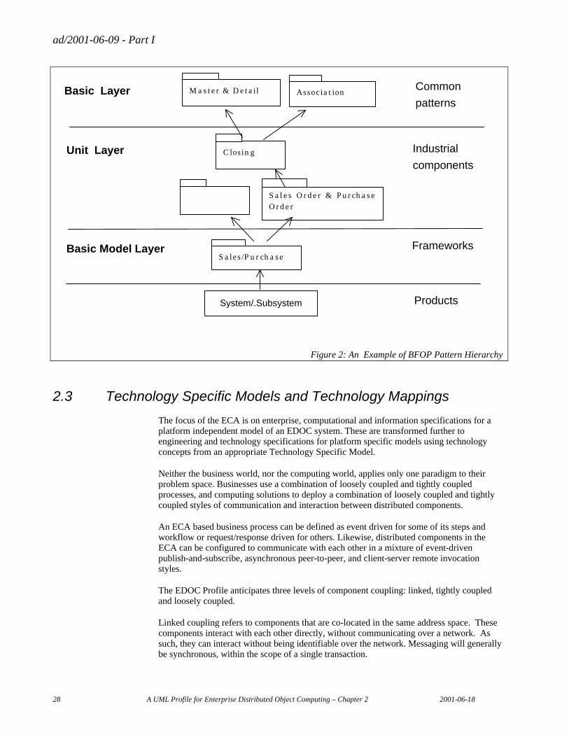
ad/2001-06-09 - Part I
28 A UML Profile for Enterprise Distributed Object Computing – Chapter 2 2001-06-18
Basic Layer M a s t e r & D e t a il Associa t ion
Unit Layer
Basic Model Layer
C losin g
S a l e s O r d e r & P u r ch a s e O r d e r
S a les /P u r ch a s e
System/.Subsystem
Common
patterns
Industrial
components
Frameworks
Products
Figure 2: An Example of BFOP Pattern Hierarchy
2.3 Technology Specific Models and Technology Mappings
The focus of the ECA is on enterprise, computational and information specifications for a platform independent model of an EDOC system. These are transformed further to engineering and technology specifications for platform specific models using technology concepts from an appropriate Technology Specific Model.
Neither the business world, nor the computing world, applies only one paradigm to their problem space. Businesses use a combination of loosely coupled and tightly coupled processes, and computing solutions to deploy a combination of loosely coupled and tightly coupled styles of communication and interaction between distributed components.
An ECA based business process can be defined as event driven for some of its steps and workflow or request/response driven for others. Likewise, distributed components in the ECA can be configured to communicate with each other in a mixture of event-driven publish-and-subscribe, asynchronous peer-to-peer, and client-server remote invocation styles.
The EDOC Profile anticipates three levels of component coupling: linked, tightly coupled and loosely coupled.
Linked coupling refers to components that are co-located in the same address space. These components interact with each other directly, without communicating over a network. As such, they can interact without being identifiable over the network. Messaging will generally be synchronous, within the scope of a single transaction.

ad/2001-06-09 - Part I
2001-06-18 A UML Profile for Enterprise Distributed Object Computing – Chapter 2 29
Tightly coupled components are distributed across multiple servers. These components will also interact with synchronous messaging, but messaging will occur over a network. While some messaging between the components may be asynchronous for performance and recoverability considerations, components are tightly coupled if any interactions between them are synchronous.
Loosely coupled components are distributed and only communicate asynchronously, through a messaging infrastructure. Communication is through messages and events. A message or event is issued in the scope of one transaction and accepted by one or more recipients in independent transactions. Messages and events are stored and forwarded. A message is a communicated with a defined recipient, and an event is a communicated (published) with self-declaring recipients (subscribers) unknown to the publisher.
The level of coupling between components has important performance and system flexibility implications. Generally, components should be designed in a level-of-coupling hierarchy so that components that are linked are within components that are tightly coupled, and tightly coupled components are then loosely coupled with each other. This coupling hierarchy should be reflected in the network accessibility property of components and the synchronous vs. asynchronous property of their ports.
With a consistent mapping to a particular technology, implementations of independently developed specifications should be operationally interoperable. Furthermore, components implemented with different technologies should be operationally interoperable if the technology mappings are consistent with the transformations provided by bridges between the technologies.
ECA based specifications can be mapped down to various technology choices, and in particular both container-managed components and message-based services. Two Technology Specific Models are defined as part of the EDOC Profile, for Enterprise Java Beans and Java enterprise computing architectures, and for the Flow Composition Model (FCM).
The EJB metamodel captures the concepts that will be used to design an Enterprise JavaBean-based application down to the Java implementation classes. The metamodel includes the assembly and deployment descriptor
FCM is a general-purpose model that supports creating flow compositions of components and defining behaviors of those compositions using wiring diagrams. It provides a common set of technology abstractions across a variety of flow model types used in message brokering. FCM is closely tied to MQ-Series but it has more general applicability and is positioned as a layer of abstraction just above middleware technology,in contrast to the ECA Processes profile which is intended technology neutral and intended for use in an analysis level model.
Normative mappings from ECA to these models is the subject of future RFPs. Proof of concept mappings are given in Part II.
ad/2001-06-09 - Part I
30 A UML Profile for Enterprise Distributed Object Computing – Chapter 2 2001-06-18
3. Application of the EDOC Profile Elements
3.1 Separation of Concerns and Viewpoint Specifications
The RFP states that:
“Successful implementation of an enterprise computing system requires the operation of the system to be directly related to the business processes it supports. A good object-oriented model for an enterprise computing system must therefore provide a clear connection back to the business processes and business domain that are the basis for the requirements of the system. However, this model must also be carried forward into an effective implementation architecture for the system. This is not trivial because of the demanding nature of the target enterprise distributed computing environment.”1
This is reflected in the vision for this EDOC profile to provide:
• …
• A development approach that allows two-way traceability between the specification, implementation and operation of Enterprise computing systems and the business functions that they are designed to support;
• …
• In order to clearly and coherently address these requirements, the specification of an EDOC system must be structured to address a number of distinct sets of concerns:
• The behavior of the system, in the context of the business for which it is implemented (i.e. its roles in some enterprise that is greater than it itself), has to be specified in a way that can be traceably linked to its design.
• The structure of the application processing carried out by the system has to be defined in terms of configurations of objects and the interactions between them.
• The semantics of the application processing carried out by the system have to be expressed in a way that can be traceably linked from its roles through to the functions the system provides.
• The infrastructure of the system has to be defined in terms of the use of object services to support the application processing structure.
• The qualitative aspects of the system (e.g. performance and reliability objectives) have to be defined together with the hardware and software products that realize the system. These determine the physical configuration of application processing and supporting services across available resources, and how the system is managed.
This is the problem addressed by the Reference Model of Open Distributed Processing (RM-ODP) [1-3] and this submission uses as the conceptual framework for an EDOC system specification the concept of viewpoints defined in the RM-ODP. It partitions a system specification into five viewpoint specifications, namely:
• the enterprise specification, 1 RFP p19 under the heading of “Enterprise Computing Systems”
ad/2001-06-09 - Part I
2001-06-18 A UML Profile for Enterprise Distributed Object Computing – Chapter 2 31
• the computational specification,
• the information specification,
• the engineering specification, and
• the technology specification.
The set of linked specifications, taken together, ensure that the system can be implemented and operated in such a way that its behavior will meet the business needs of its owners, and, furthermore, that its owners will understand the constraints on their business that operation of the system will impose.
This section explains how the concepts defined by in the EDOC Profile can be used to develop a full set of viewpoint specifications for an EDOC system and how specification integrity across the various viewpoint specifications can be ensured. In summary (Figure 3):
• the CCA, the Events profile, the Entities profile the Processes profile and the Relationships profile from the ECA are used, with relevant Patterns, to produce an enterprise specification (Enterprise viewpoint);
• the CCA, the Entities profile and the Events profile from the ECA are used, with relevant Patterns, to produce a computational specification (Computational viewpoint);
• the Entities profile and Relationships profile from the ECA are used, with relevant Patterns, to produce an information specification (Information viewpoint);
• A technology abstraction model such as the Flow Composition Model (FCM), with relevant Patterns, is used to produce an engineering specification (Engineering viewpoint);
• the mappings from DCP to various technologies, in particular, to J2EE with EJB, to CORBA 3 with CCM and to MS DNA/.NET with DCOM, are used to produce technology specifications (Technology viewpoint).
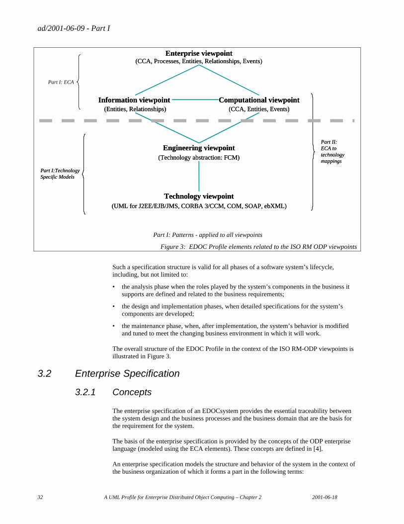
ad/2001-06-09 - Part I
32 A UML Profile for Enterprise Distributed Object Computing – Chapter 2 2001-06-18
Enterprise viewpoint(CCA, Processes, Entities, Relationships, Events)
Enterprise viewpoint(CCA, Processes, Entities, Relationships, Events)
Information viewpoint (Entities, Relationships) (CCA, Entities, Events)
Computational viewpointInformation viewpoint (Entities, Relationships) (CCA, Entities, Events)
Computational viewpoint
Technology viewpoint(UML for J2EE/EJB/JMS, CORBA 3/CCM, COM, SOAP, ebXML)
Technology viewpoint(UML for J2EE/EJB/JMS, CORBA 3/CCM, COM, SOAP, ebXML)
Part I:Technology Specific ModelsPart I:Technology Specific Models
Part II: ECA totechnology mappings
Part II: ECA totechnology mappings
Part I: ECA
(Technology abstraction: FCM)
Engineering viewpoint(Technology abstraction: FCM)
Engineering viewpoint
Part I: Patterns - applied to all viewpoints
Figure 3: EDOC Profile elements related to the ISO RM ODP viewpoints
Such a specification structure is valid for all phases of a software system’s lifecycle, including, but not limited to:
• the analysis phase when the roles played by the system’s components in the business it supports are defined and related to the business requirements;
• the design and implementation phases, when detailed specifications for the system’s components are developed;
• the maintenance phase, when, after implementation, the system’s behavior is modified and tuned to meet the changing business environment in which it will work.
The overall structure of the EDOC Profile in the context of the ISO RM-ODP viewpoints is illustrated in Figure 3.
3.2 Enterprise Specification
3.2.1 Concepts
The enterprise specification of an EDOCsystem provides the essential traceability between the system design and the business processes and the business domain that are the basis for the requirement for the system.
The basis of the enterprise specification is provided by the concepts of the ODP enterprise language (modeled using the ECA elements). These concepts are defined in [4].
An enterprise specification models the structure and behavior of the system in the context of the business organization of which it forms a part in the following terms:
ad/2001-06-09 - Part I
2001-06-18 A UML Profile for Enterprise Distributed Object Computing – Chapter 2 33
• the business processes supported by the system;
• steps in those processes and relationships between steps;
• business rules (policies) that apply to the steps;
• artifacts acted on by each step
• enterprise objects representing the business entities involved,
• the roles that they fulfil in supporting the business processes and
• the relationships between roles (including interaction relationships) where roles identify responsibility for steps in the business processes.
An EDOC system or each component of that system is modeled as an enterprise object and is assigned a role or roles in the community: hence, it is associated with specific parts of one or more processes. These roles identify the parts of the business processes for which the system is responsible and the artifacts that are involved. Such artifacts and resources represent the information held and acted upon by the system.
The central concept of any enterprise specification is that of a community that models a collection of entities interacting to achieve some purpose, which is defined by the objective of the community concerned. Each community is modeled as a configuration of enterprise objects in roles. The EDOC system of concern (or the components of that system) is modeled as one or more of the enterprise objects that are the members of the community.
The behavior of the members of the community is identified by the roles they fulfil, and is defined in terms of a set of actions, each of which may also be modeled as a step of one or more processes. Each process is designed to achieve the objective of the community.
Depending upon what it models, an enterprise object may be further refined as a community in a process of recursive decomposition.
Policies (business rules) may be associated with any other enterprise language concept and may be expressed in the form of constraints on any concept, or relationship between two concepts.
3.2.2 EDOC Enterprise Subprofile
The EDOC enterprise specification makes use of the CCA for the role-based definition of the enterprise structure, where:
• communities are modeled as Composed Components with associated Composition and Choreography definitions.
• enterprise objects are modeled as ProcessComponents;
• the interactions in which enterprise objects can participate are defined by Ports and the associated Protocols.
It makes use of the Processes profile for the process-based definition of the enterprise structure.
It makes use of the Event profile for the definition of event driven enterprise structures.
It makes use of the Entities profile for the definition of entities and rules. Artifacts, performers and responsible parties, which are the subject of the interactions, are modeled as entities
ad/2001-06-09 - Part I
34 A UML Profile for Enterprise Distributed Object Computing – Chapter 2 2001-06-18
It makes use of the Relationships profile for rigorous specification of relationships.
3.3 Computational Specification
3.3.1 Concepts
The computational specification describes the implementation of the EDOC system (or components that comprise that system) in order to carry out the processing required by the system roles in the enterprise specification. It does this in terms of functional decomposition of the system into computational objects that interact at interfaces, and thereby enables distribution. It defines:
• Computational objects that play some functional role in the system and which can be described in terms of provided interfaces and used interfaces: a set of computational objects will correspond to the implementation of roles of the system in enterprise processes, and associated enterprise events and business rules;
• The interfaces at which the computational objects interact: this includes different types of interfaces and also describes data involved in computational interactions corresponding to the information objects in the information specification;
• The collaboration structures among a set of computational objects.
The computational viewpoint is closely related to the enterprise viewpoint in that the computational objects represent a functional mapping of enterprise concepts like business processes, rules, events etc. where these relate to the roles of the system in the enterprise specification. Ways of ensuring consistency (conformance/reference points) between enterprise and computational specifications should be supported (consistency statements for corresponding conformance/reference points in the two viewpoint specifications).
The EDOC computational specification concepts are based on the RM-ODP Part 3 Clause 7 [3].
3.3.2 EDOC Computational Specifications
An EDOC computational specification makes use of the CCA for the basic definition of the computational structure, where:
• Computational objects are modeled as ProcessComponents;
• The interfaces at which computational objects interact are modeled by Ports;
• Collaboration structures among a set of computational objects are modeled by Compositions with associated Choreographies.
It makes use of the Entities Model for the definition of entity components, where entity components correspond to entities in the information specification.
It makes use of the Events Model for the definition of event driven computational structures.
3.3.3 Levels of ProcessComponent in a Computational Specification
An EDOC computational specification can specify ProcessComponents at a number of different levels. These levels correspond to four general categories of ProcessComponent:
ad/2001-06-09 - Part I
2001-06-18 A UML Profile for Enterprise Distributed Object Computing – Chapter 2 35
• E-Business Components
• Application Components
• Distributed Components
• Program Components
3.3.3.1 E-Business Components
E-Business Components are used as the integration point between enterprises, enterprises and customers or somewhat independent parts of a large enterprise (such as an acquired division). Interfaces to E-Business Components will frequently be directly accessible on the Internet as part of a web portal.
The E-Business Component has the potential to spawn new forms of business and new ways for business to work together.
E-Business Components integrate business entities that may share no common computing management or infrastructure. Interactions between E-Business components must be very loosely coupled and are always asynchronous. No assumptions of shared resources may be made between the parties, and the internals of the E-Business components will frequently be changed without informing other parties.
3.3.3.2 Application Components
Application Components represent new and legacy applications within an enterprise. Application Components are used to integrate applications (EAI) and create new applications, frequently to facilitate E-Business Components.
Application Components represent large-grain functional units. Each Application Component may be implemented in different technologies for different parts of the enterprise. Integrating Application Components facilitates enterprise-wide business processes and efficiencies.
Individual Application Components may be individually managed, but the integration falls under common management that may impose standards for interoperability and security.
Application Components use a wide variety of integration techniques including messaging, events, Internet exchanges and object or procedural RPC. Application Components are frequently wrapped legacy systems.
3.3.3.3 Distributed Components
Distributed Components are functional parts of distributed applications. These components are generally integrated within a common middleware infrastructure such as EJB, CORBA Components or DCOM. Distributed components have well defined interfaces and share common services and resources within an application.
Distributed Components provide for world-wide applications that can use a variety of technologies. Most distributed component interactions are synchronous.
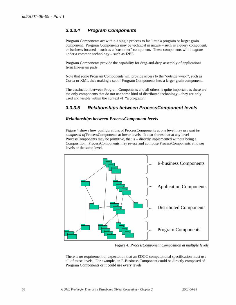
ad/2001-06-09 - Part I
36 A UML Profile for Enterprise Distributed Object Computing – Chapter 2 2001-06-18
3.3.3.4 Program Components
Program Components act within a single process to facilitate a program or larger grain component. Program Components may be technical in nature – such as a query component, or business focused – such as a “customer” component. These components will integrate under a common technology – such as J2EE.
Program Components provide the capability for drag-and-drop assembly of applications from fine-grain parts.
Note that some Program Components will provide access to the “outside world”, such as Corba or XML thus making a set of Program Components into a larger grain component.
The destination between Program Components and all others is quite important as these are the only components that do not use some kind of distributed technology – they are only used and visible within the context of “a program”.
3.3.3.5 Relationships between ProcessComponent levels
Relationships between ProcessComponent levels
Figure 4 shows how configurations of ProcessComponents at one level may use and be composed of ProcessComponents at lower levels. It also shows that at any level ProcessComponents may be primitive, that is – directly implemented without being a Composition. ProcessComponents may re-use and compose ProcessComponents at lower levels or the same level.
E-business Components
Application Components
Distributed Components
Program Components
Figure 4: ProcessComponent Composition at multiple levels
There is no requirement or expectation that an EDOC computational specification must use all of these levels. For example, an E-Business Component could be directly composed of Program Components or it could use every levels
ad/2001-06-09 - Part I
2001-06-18 A UML Profile for Enterprise Distributed Object Computing – Chapter 2 37
3.4 Information Specification
3.4.1 Concepts
The information specification defines the semantics of information and information processing involved in the parts of the business processes carried out by the EDOC system (or by components that comprise that system). The information specification concepts are taken from the RM-ODP Part 3 Clause 6 [3].
The information specification is expressed in terms of
• a configuration of information objects (static schema),
• the behavior of those information objects (dynamic schema) and
• the constraints that apply to either of the above (invariant schema).
The information objects identified correspond to enterprise objects in the enterprise specification for which information is held and processed by the system.
The structure of the information objects and the relationships between them are defined in terms of static (structural) configurations of information objects. This includes the structure of individual information objects and the structure comprising a set of related information objects.
The behavior of the interrelated information objects is defined in terms of state changes that can occur and relate to the effects of the process steps in the enterprise specification.
The constraints relate to the business rules that apply to the process steps in the enterprise specification and define predicates on the information objects that must always be true.
3.4.2 EDOC Information Specifications
An EDOC information specification makes use of the Entities profile and the Relationships profile for the basic definition of the information structure, where:
• information objects are modeled as Entities and Relationships;
• constraints are defined in terms of enumerated states, relationship properties and invariants from UML.
It makes use of the Choreography from the CCA for the definition of behavior of Entities in terms of changes of EntityState.
It makes use of the Relationships profile for rigorous specification of relationships.
3.5 Engineering Specification
3.5.1 Concepts
The engineering specification defines the distribution transparency requirements and the services required to provide these transparencies in support of the processing specified by the computational specification. In addition, the engineering specification describes the means by which distribution is provided. The engineering specification concepts are taken from the RM-ODP Part 3 Clause 8 [3]
ad/2001-06-09 - Part I
38 A UML Profile for Enterprise Distributed Object Computing – Chapter 2 2001-06-18
The engineering specification is derived from the computational specification by applying a technology mapping. The technology mapping incorporates standard interface and naming protocols to define consistent interface types and specifications.
The engineering specification will also incorporate additional design decisions. One of the key aspects of the engineering specification is the strategy for distributed computing, governing such issues as:
• which objects are network accessible and which are not: objects that are not network accessible must be co-located with objects with which they have relationships or from which they receive messages;
• the scope of transactions and the use of asynchronous messaging;
• which elements are persistent and how they are mapped to a persistent data store.
The engineering specification provides the basis for code generation. Currently, the ECA elements along with current UML design facilities can provide specifications for code to implement the objects, their interfaces, code to assure model integrity and methods to support certain services and protocols. Humans will still be required to program the business logic of methods and processes.
3.5.2 EDOC Engineering Specifications
These are defined by mapping from the computational specification to a technology abstraction model such as FCM. Examples of such mappings are given on Pat II.
3.6 Technology Specification
The technology specification is concerned with the choice and deployment of software and hardware products for implementing the system and with the associated mappings from technology abstraction models such as FCM to the corresponding technologies (e.g. J2EE with EJB, Flow Composition Model (FCM), CORBA 3 with CCM and MS DNA/.Net with DCOM).
3.7 Specification Integrity - Interviewpoint Correspondences
This section identifies relationships that are required to exist between viewpoint specifications and are expressed through relationships between elements in different viewpoint specifications.
3.7.1 Computational-Enterprise Interrelationships
A Process in the computational specification is related one or more sets of Activities in one or more Processes in the enterprise specification, where performance of those Activities is the responsibility of the EDOC system. It may also be related to Business Rules that apply to those Activities.
An Entity in the computational specification is related to a Entity referenced (as an artifact) in at least one Activity in a Process in the enterprise specification, where the Activity is the responsibility of the EDOC system.
A BusinessNotification in the computational specification is related to a BusinessNotification associated with an Activity in a Process in the enterprise specification, where the Activity is the responsibility of the EDOC system.
ad/2001-06-09 - Part I
2001-06-18 A UML Profile for Enterprise Distributed Object Computing – Chapter 2 39
A Rule in the computational specification is related to a Rule that applies to Activities in one or more Processes in the enterprise specification, where the Activities are the responsibility of the EDOC system.
3.7.2 Computational-Information Interrelationships
A Entity in the computational specification is related to an entity or a configuration of Entities in a static schema in the information specification.
A Process in the computational specification is related to a Choreography in the information description and can be related also to an invariant schema.
A BusinessNotification in the computational specification is related to a Choreogrphy in the information description.
A Rule in the computational specification is related to an invariant schema in the information specification.
3.7.3 Computational-Engineering Interrelationships
These depend upon the specific technology mappings that are applied.
3.7.4 Engineering-Technology Interrelationships
These depend upon the specific technology mappings that are applied.
ad/2001-06-09 - Part I
40 A UML Profile for Enterprise Distributed Object Computing – Chapter 3 2001-06-18
Chapter 3 The Enterprise Collaboration Architecture
Table of Contents
1. ECA Design Rationale .................................................................................................................................... 43 1.1 Key Design Features............................................................................................................................... 43
1.1.1 Recursive component composition ............................................................................................... 43 1.1.2 Process Specification .................................................................................................................... 45 1.1.3 Specification of Event Driven Systems ......................................................................................... 45 1.1.4 Integration of Process and Information Models ............................................................................ 46 1.1.5 Rigorous relationship specification.............................................................................................. 47 1.1.6 Mappings to Technology - Platform Independence ...................................................................... 47
1.2 ECA Elements ........................................................................................................................................ 48
2. The Component Collaboration Architecture ................................................................................................... 50 2.1 Rationale................................................................................................................................................. 50
2.1.1 Problems to be solved ................................................................................................................... 50 2.1.2 Approach....................................................................................................................................... 53 2.1.3 Concepts........................................................................................................................................ 53 2.1.4 Conceptual Framework ................................................................................................................. 56
2.2 CCA Metamodel..................................................................................................................................... 58 2.2.1 Structural Specification................................................................................................................. 58 2.2.2 Choreography................................................................................................................................ 76 2.2.3 Composition.................................................................................................................................. 86 2.2.4 Document Model........................................................................................................................... 97 2.2.5 Model Management .................................................................................................................... 107
2.3 CCA Notation....................................................................................................................................... 110 2.3.1 CCA Specification Notation........................................................................................................ 110 2.3.2 Composite Component Notation................................................................................................. 111 2.3.3 Community Process Notation...................................................................................................... 113
2.4 UML Profile ......................................................................................................................................... 113 2.4.1 Tables mapping concepts to profile elements ............................................................................. 113 2.4.2 ECA::CCA «profile» Package .................................................................................................... 114 2.4.3 Introduction................................................................................................................................. 116 2.4.4 Stereotypes for Structural Specification...................................................................................... 118 2.4.5 Stereotypes for Choreography..................................................................................................... 133 2.4.6 Stereotypes for Composition....................................................................................................... 140 2.4.7 DocumentModel «profile» Package............................................................................................ 146 2.4.8 UML Model_Management Package ......................................................................................... 150 2.4.9 Relationships............................................................................................................................... 151 2.4.10 General OCL Definition Constraints.......................................................................................... 171
2.5 Diagramming CCA............................................................................................................................... 171 2.5.1 Types of Diagram........................................................................................................................ 171 2.5.2 The Buy/Sell Example ................................................................................................................ 172 2.5.3 Collaboration diagram shows community process ...................................................................... 172 2.5.4 Class diagram for protocol structure ........................................................................................... 174 2.5.5 Activity Diagram (Choreography) for a Protocol........................................................................ 176
ad/2001-06-09 - Part I
2001-06-18 A UML Profile for Enterprise Distributed Object Computing – Chapter 3 41
2.5.6 Class Diagram for Component Structure..................................................................................... 177 2.5.7 Class Diagram for Interface ........................................................................................................ 179 2.5.8 Class Diagram for Process Components with multiple ports ...................................................... 181 2.5.9 Activity Diagram showing the Choreography of a Process Component...................................... 182 2.5.10 Collaboration Diagram for Process Component Composition .................................................... 182 2.5.11 Model Management .................................................................................................................... 185 2.5.12 Using the CCA Notation for Component & Protocol Structure .................................................. 186
3. The Entities Profile ....................................................................................................................................... 188 3.1 Introduction .......................................................................................................................................... 188
3.1.1 Normative sections...................................................................................................................... 188 3.1.2 Relationship to other parts of ECA ............................................................................................. 188 3.1.3 Design Concepts ......................................................................................................................... 189 3.1.4 Standard UML Facilities ............................................................................................................. 194
3.2 Entity viewpoints .................................................................................................................................. 195 3.2.1 Information viewpoint................................................................................................................. 195 3.2.2 Composition viewpoint ............................................................................................................... 196
3.3 Entity Metamodel ................................................................................................................................. 197 3.3.1 Overview..................................................................................................................................... 197 3.3.2 Entity Package............................................................................................................................. 198
3.4 Entity UML Profile............................................................................................................................... 209 3.4.1 Metamodel Mapping to Profile ................................................................................................... 209 3.4.2 Entity Package............................................................................................................................. 209
4. The Events Profile......................................................................................................................................... 219 4.1 Rationale............................................................................................................................................... 219
4.1.1 Introduction................................................................................................................................. 219 4.1.2 Overall design rationale .............................................................................................................. 220 4.1.3 Concepts...................................................................................................................................... 221 4.1.4 Key Concepts of event driven business and system models........................................................ 223 4.1.5 Event and Notification based Interaction Models ....................................................................... 225 4.1.6 Leveraging event based models .................................................................................................. 228
4.2 Metamodel............................................................................................................................................ 230 4.2.1 Publish and Subscribe Package................................................................................................... 233 4.2.2 Event Package............................................................................................................................. 240
4.3 UML Profile ......................................................................................................................................... 248 4.3.1 Table mapping concepts to profile elements............................................................................... 248 4.3.2 Introduction................................................................................................................................. 248 4.3.3 Publish and Subscribe Package................................................................................................... 248 4.3.4 Event Package 2 .......................................................................................................................... 252
4.4 Relationship to other ECA profiles....................................................................................................... 257 4.4.1 Relationship to Business Processes profile and Entities profile .................................................. 257 4.4.2 Relationship to ECA CCA profile............................................................................................... 258
4.5 Relationship other paradigms ............................................................................................................... 258 4.6 Example................................................................................................................................................ 260
5. The Business Processes Profile ..................................................................................................................... 262 5.1 Introduction .......................................................................................................................................... 262 5.2 Metamodel............................................................................................................................................ 262
5.2.1 Business Business Process metamodel........................................................................................ 268 5.3 UML Profile ......................................................................................................................................... 287
5.3.1 Table mapping concepts to profile elements............................................................................... 287 5.3.2 BusinessProcess «profile» Package ............................................................................................ 288 5.3.3 Relationships............................................................................................................................... 308
5.4 Notation for Activity and ProcessRole ................................................................................................. 309 5.5 Process Model Patterns......................................................................................................................... 311
5.5.1 Timeout....................................................................................................................................... 312 5.5.2 Terminate .................................................................................................................................... 313 5.5.3 Activity Preconditions and Activity Postconditions.................................................................... 313 5.5.4 Simple Loop................................................................................................................................ 315 5.5.5 While and Repeat-Until Loops.................................................................................................... 316
ad/2001-06-09 - Part I
42 A UML Profile for Enterprise Distributed Object Computing – Chapter 3 2001-06-18
5.5.6 For Loop ..................................................................................................................................... 317 5.5.7 Multi-Task................................................................................................................................... 318
5.6 Full Model ............................................................................................................................................ 318
6. The Relationships Profile .............................................................................................................................. 320 6.1 Requirements ........................................................................................................................................ 320
6.1.1 Introduction................................................................................................................................. 320 6.1.2 Non-Binary Relationships ........................................................................................................... 321 6.1.3 Example: Mutually Orthogonal Non-Binary Aggregations......................................................... 322 6.1.4 Example: Multiple Subtyping ..................................................................................................... 324 6.1.5 Other Relationship Requirements ............................................................................................... 325
6.2 Using UML to Address the Requirements: An Overview..................................................................... 325 6.3 Formal Virtual Metamodel of the UML Extensions ............................................................................. 325
6.3.1 Aggregations ............................................................................................................................... 326 6.3.2 Reference Relationships.............................................................................................................. 333
6.4 Mapping the Relationships to Technical Platforms .............................................................................. 336 6.4.1 Aggregations ............................................................................................................................... 337 6.4.2 Reference Relationships.............................................................................................................. 340
6.5 Examples Using the UML Extensions .................................................................................................. 340 6.5.1 Example: List and Subordination................................................................................................ 340 6.5.2 Example: Reference Relationships.............................................................................................. 342
ad/2001-06-09 - Part I
2001-06-18 A UML Profile for Enterprise Distributed Object Computing – Chapter 3 43
1. ECA Design Rationale
This chapter describes the Enterprise Collaboration Architecture (ECA) – a model-driven architecture approach for specifying Enterprise Distributed Object Computing systems.
This chapter is divided into the following sections:
This section provides the design rational for the ECA.
Sections 2 to 6 define the elements of the ECA:
• Component Collaboration Architecture (CCA) Profile,
• Entities profile;
• Events profile;
• Business Processes profile;
• Relationships profile
1.1 Key Design Features
Five key design features of the ECA address the EDOC vision:
• Recursive component composition;
• Support for event-driven systems;
• Process specification;
• Integration of process and information models;
• Technology independence, allowing implementation of a design using different technologies.
1.1.1 Recursive component composition
Business processes are by their very nature collaborations – a set of people, departments, divisions or companies, working together to achieve some purpose or set of purposes.
Such a collaboration can be viewed as a “composition” with the people, departments etc as “components” of that composition having “roles” that represent how each component is to behave within the composition (note that the same component may have different roles in the same or different compositions, just as a person, department etc. may have many roles with respect to many processes).
This dynamic of component and composition is fundamental, the concept of component only makes sense with respect to some specific kind of composition and the concept of composition only makes sense when there can be components to compose it.
When a high-level business process is considered, such as buying and selling, there are roles within this buy-sell process for the buyer and seller. In some cases there may be other roles, such as banks, freight forwarders and brokers. Each of these is

ad/2001-06-09 - Part I
44 A UML Profile for Enterprise Distributed Object Computing – Chapter 3 2001-06-18
defined as a component within the high-level process, e.g. it is a component of the “buy-sell” process, playing some role.
Besides identifying the roles it is necessary to identify how each of the components must interact with the other components for the process to unfold. Thus, for each kind of interaction that exists between roles there is a protocol for that interaction defined by the information that flows and the timing of that flow, for example the interaction of the seller with a freight forwarder is completely different from the interaction with the buyer. This leads to the next important concept – that of interactions. Interactions are well defined protocols between roles within some composition. Each interaction point on a component is called a “port”, which is the point of interaction of roles.
Finally, reflecting what is seen in the world, it is necessary to allow “drill down” from one level of granularity to another. When you place an order on the web you see a single face (the web portal) playing a single role (the seller). This simplified view represents the seller’s role in the buy-sell process (you represent the other role). Inside of the seller, when it is opened up, you see order processing, credit, warehousing, shipping – all of the roles it takes to get you your order. This more fine-grain process represents the way a particular component has been configured to play the role of the seller, another seller may involve other choices.
Adding this concept of drill-down takes us from “flat” component composition to recursive component composition – the ability to define components as compositions of finer grain components.
Thus, components are defined in terms of sub-components playing roles and interacting through ports. At the highest level, processes are self-contained, the entire community of roles is identified. When you “open up” one of the components you may find a “primitive” component, one defined in terms of pre-established constructs such as may be found in Java or the UML Action language. The other thing you may find is another composition. What looks like an atomic component at one level may reveal a complex lattice of sub-components when “opened up”.
A recursive component architecture can be used “top down”, by defining new processes in terms of higher level compositions. It can also be used “bottom up” by assembling existing components into new compositions – making new components. As new basic capabilities are required they can either by defined from existing components or new primitive components can be supplied, so there is no “brick wall” when some fundamental capability you need was not anticipated.
In such a recursive component architecture there is a clear separation between the “inside” of a component and its “outside”. The outside of a component exposes a set of named ports, each with a defined interaction that connects it with a compatible port in another component. These ports specify what information flows between the compatible components and under what conditions the information flows. The outside of a component is not concerned with the internal composition or process of the component.
One other aspect of component technology is that of configurability. Components may be very general in nature, which promotes reuse. These very general components must be configured when used in a specific role. This may be seen in the property panels of bean-boxes or COM components. The ability to configure a component is essential to making it general and reusable. We call a configuration point a “property”.
To summarize the points;
• The concepts of component and composition are fundamentally tied.
• Components may be primitive or compositions of sub-components
ad/2001-06-09 - Part I
2001-06-18 A UML Profile for Enterprise Distributed Object Computing – Chapter 3 45
• Each component can play roles within other compositions.
• Components interact with each other, within composite processes, through ports.
• Component composition is recursive, allowing decomposition and assembly.
The advantages of this approach are
• A single simple paradigm describes large grain and fine grain process components.
• Components are reusable across many compositions
• New components may be defined as collaborations of existing components
• New fundamental capabilities may defined as primitive components.
• The collaborative and recursive nature of processes may be directly represented.
1.1.2 Process Specification
The modeling of processes in the ECA profile addresses an RFP requirement, but, more importantly, processes are important elements in the representation of interactions between components, systems and enterprises. Processes are the mechanisms of collaborations. Processes define the roles of the participants and artifacts involved in collaborations. Processes also define the manner in which events can drive the operation of the enterprise. Consequently, it is essential that the ECA model include a representation of processes that enables a modeler to define a framework for the operation of an enterprise.
The modeling of processes in the ECA profile reflects the OMG Workflow Management Facility model. A process contains activities, which perform the actions of the process. The activities may invoke other processes, and they may employ resources. The Workflow Management Facility resource interface represents the participation of that resource, i.e., a role in the ECA context. The resource/role captures the state and supports the interaction between the activity and a potentially wide variety of resources.
The ECA model goes slightly beyond the Workflow Management Facility specification. First, it extends the resource concept by defining performers and artifacts (active and passive participants). Second, it adds the ability to attach pre and post conditions to activities. These are concepts that are consistent with workflow management concepts and provide basic flow control mechanisms. These were not addressed in the Workflow Management Facility specification because it focused primarily on interoperability between workflow management systems.
The ECA profile does not attempt to define a representation of the action semantics of processes, nor does it define the relationship of processes to organizations or applications. These are left to other RFPs to be addressed by specialists in these areas.
1.1.3 Specification of Event Driven Systems
Event driven computing is becoming the preferred distributed computing paradigm in many enterprises and in many collaborations between enterprises. Event driven computing combines two kinds of loosely coupled architectures.
The first one is loosely coupled, distributed components that communicate with each other through asynchronous messaging.
ad/2001-06-09 - Part I
46 A UML Profile for Enterprise Distributed Object Computing – Chapter 3 2001-06-18
The other one is loosely coupled business process execution. Here enterprises collaborate under an overall long term contract, but do not execute their day to day interaction in traditional workflow, or request/response style interaction.
In event driven computing the most important aspect of a process is the events that happen during its execution, and the most important part of the component-to-component communication is the notification of such events from the party that made them happen to all the parties that need to react to them.
In ECA we support both the definition of loosely coupled business processes, as well as the loosely coupled communication between distributed components.
Neither the world, nor the computing world, however, apply only one paradigm to their problem space. Businesses use a combination of loosely coupled and tightly coupled processes, and computing solutions deploy a combination of loosely coupled and tightly coupled styles of communication and interaction between distributed components.
An ECA process can be defined as event driven for some of its steps and workflow or request/response driven for others. ECA distributed components can be configured to communicate with each other in a mixture of event-driven publish-and-subscribe, asynchronous peer-to-peer, and client-server remote invocation styles.
The essential elements of the purely event driven approach are:
• Business Process objects are configured with a set of Business Rule parameters that determine what Business Events trigger actions, and what the action should be.
• Business Process objects operate on Business Entity objects which represent people, products, and other business resources and artifacts.
• When actions are performed on Business Entity objects, Business Events happen.
• All Business Entity objects are capable of notifying the world of events that happen to them.
• All Business Process objects are capable of subscribing to such events and interpreting them throughout their set of business rules.
1.1.4 Integration of Process and Information Models
IT systems are specified with entity and process models, where entity models describe the things (entities, attributes, relationships, invariants) in the IT system and process models specify the processes, sub-processes, activities, resources, roles, and rules of IT system behavior.
Information modeling tools, such as those based on the UML metamodel, are used to specify entity models. Process definition tools, such as those provided by BPR and workflow vendors, are used to specify process models. As these entity model and process model tools are based on different metamodels, the integration of their models into the IT system specification is a problem.
IT system designers and developers typically work round the problem by looking at one model, then the other, and then do their own composition for that moment (perhaps influenced by memories of other compositions). One result of this is that the normative entity and process models when composed, by each individual at multiple moments in time, become non-normative individual interpretations of the IT system specification. Also of concern is the impact of model changes to the
ad/2001-06-09 - Part I
2001-06-18 A UML Profile for Enterprise Distributed Object Computing – Chapter 3 47
composition – evolution of process and entity models is reasonably certain, especially during IT system development projects.
This submission specifies how the UML metamodel may be extended to become a common underlying metamodel for expressing IT system entities, processes, and their relationships,. Although entity and process modeling styles are very different, their underlying metamodels are not and thus the process and information viewpoints can be reconciled.
With this metamodel UML, workflow, and BPR vendors can provide new tools that combine entity-orientated and process-orientated modeling techniques to produce integrated IT system models..
1.1.5 Rigorous relationship specification
Rigorous relationship specification is a major aspect of business modeling and software modeling. The semantics of a class diagram is shown in its structure – the collections of “lines” – that has to be defined by means of appropriate invariants and represented graphically. Moreover, relationships are fundamental to behavior because they are the paths over which actions occur, therefore clear, concise and rigorous specification of relationship semantics is of utmost importance.
Multiplicities are not the most important or most interesting properties of relationships1. Property determinations are much more important for the semantics of a relationship, and distinguish among different kinds of relationships. The fragments of relationship invariants about property determination represent an essential fragment of those elusive “business rules” that are the backbone of a good specification and that should never be only “in the code.”
At the same time, it is very desirable to discover and specify – rather than reinvent – those kinds of relationships that are encountered in all specifications, so that reuse at the specification level becomes possible. Such generic relationships extend the set of reusable constructs that already exist in UML.
It is also desirable that the approach taken for the specification of relationships should be extensible so that, if it appears that in a particular business (or a set of applications) additional generic relationships are needed and useful, then they may be precisely and explicitly defined and added in a manner similar to the existing definitions.
Generic relationships can provide concepts and constructs that permit UML to be used for specification of businesses and systems in a more rigorous manner than (and without restrictions currently imposed by) the base UML 1.3. Generic relationships can provide for explicit specification of relationship semantics in class diagrams, a line between boxes – even a named line! – should not be considered an adequate relationship specification.2
1.1.6 Mappings to Technology - Platform Independence
Viewpoint abstractions in the context of model-based development provide mechanisms for specifying platform independent models of business applications.
Such platform independence is an important element in systems that can adapt to
1 In most cases, the multiplicities follow from the generic relationship invariant and therefore do not need to be explicitly shown in the diagram: the Stereotype takes care of that. Such diagrams are less cluttered. 2 A combination of two interrelated lines required by the currently existing UML metamodel is an exception; specifically, an association line that simply mandates a link is acceptable, but only if it is paired with a <<Reference>> dependency line.
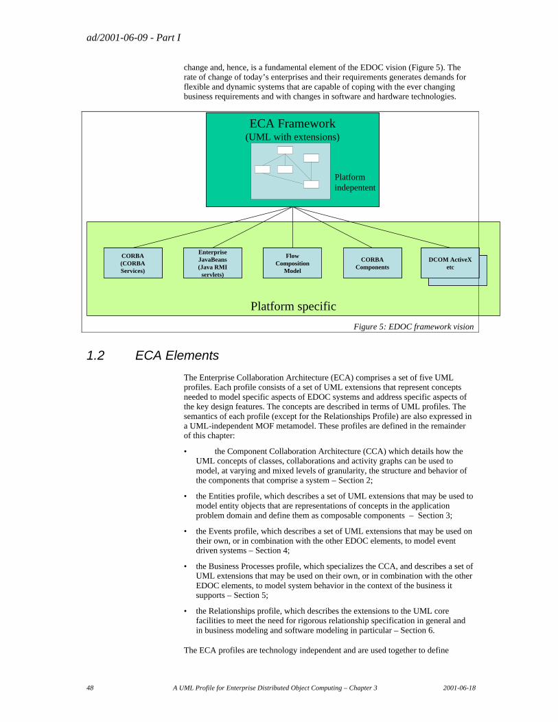
ad/2001-06-09 - Part I
48 A UML Profile for Enterprise Distributed Object Computing – Chapter 3 2001-06-18
change and, hence, is a fundamental element of the EDOC vision (Figure 5). The rate of change of today’s enterprises and their requirements generates demands for flexible and dynamic systems that are capable of coping with the ever changing business requirements and with changes in software and hardware technologies.
Platform specific
CORBA(CORBA Services)
Enterprise JavaBeans(Java RMI
servlets)DCOM ActiveX
etc
DCOM ActiveXetc
CORBA Components
Flow Composition
Model
CORBA(CORBA Services)
Enterprise JavaBeans(Java RMI
servlets)DCOM ActiveX
etc
DCOM ActiveXetcDCOM ActiveX
etc
DCOM ActiveXetc
CORBA Components
Flow Composition
Model
ECA Framework(UML with extensions)
Platformindepentent
ECA Framework(UML with extensions)
Platformindepentent
Figure 5: EDOC framework vision
1.2 ECA Elements
The Enterprise Collaboration Architecture (ECA) comprises a set of five UML profiles. Each profile consists of a set of UML extensions that represent concepts needed to model specific aspects of EDOC systems and address specific aspects of the key design features. The concepts are described in terms of UML profiles. The semantics of each profile (except for the Relationships Profile) are also expressed in a UML-independent MOF metamodel. These profiles are defined in the remainder of this chapter:
• the Component Collaboration Architecture (CCA) which details how the UML concepts of classes, collaborations and activity graphs can be used to model, at varying and mixed levels of granularity, the structure and behavior of the components that comprise a system – Section 2;
• the Entities profile, which describes a set of UML extensions that may be used to model entity objects that are representations of concepts in the application problem domain and define them as composable components – Section 3;
• the Events profile, which describes a set of UML extensions that may be used on their own, or in combination with the other EDOC elements, to model event driven systems – Section 4;
• the Business Processes profile, which specializes the CCA, and describes a set of UML extensions that may be used on their own, or in combination with the other EDOC elements, to model system behavior in the context of the business it supports – Section 5;
• the Relationships profile, which describes the extensions to the UML core facilities to meet the need for rigorous relationship specification in general and in business modeling and software modeling in particular – Section 6.
The ECA profiles are technology independent and are used together to define

ad/2001-06-09 - Part I
2001-06-18 A UML Profile for Enterprise Distributed Object Computing – Chapter 3 49
platform independent models of EDOC systems in conformance with the MDA. In particular, they enable the modeling of the concepts that until now have had to be specified programmatically in terms of the use of services such as events/ notification, support for relationships and persistence.
ad/2001-06-09 - Part I
50 A UML Profile for Enterprise Distributed Object Computing – Chapter 3 2001-06-18
2. The Component Collaboration Architecture
The Component Collaboration Architecture (CCA) details how the UML concepts of classes, collaborations and activity graphs can be used to model, at varying and mixed levels of granularity, the structure and behavior of the components that comprise a system.
2.1 Rationale
2.1.1 Problems to be solved
The information system has become the backbone of the modern enterprise. Within the enterprise, business processes are instrumented with applications, workflow systems, web portals and productivity tools that are necessary for the business to function.
While the enterprise has become more dependent on the information system the rate of change in business has increased, making it imperative that the information system keeps pace with and facilitates the changing needs of the enterprise.
Enterprise information systems are, by their very nature, large and complex. Many of these systems have evolved over years in such a way that they are not well understood, do not integrate and are fragile. The result is that the business may become dependent on an information infrastructure that cannot evolve at the pace required to support business goals.
The way in which to design, build, integrate and maintain information systems that are flexible, reusable, resilient and scalable is now becoming well understood but not well supported. The CCA is one of a number of the elements required to address these needs by supporting a scalable and resilient architecture.
The following subsections detail some of the specific problems addressed by CCA.
2.1.1.1 Recursive decomposition and assembly
Information systems are, by their very nature, complex. The only viable way to manage and isolate this complexity is to decompose these systems into simpler parts that work together in well-defined ways and may evolve independently over time. These parts can than be separately managed and understood. We must also avoid re-inventing parts that have already been produced, by reusing knowledge and functionality whenever practical.
The requirements to decompose and reuse are two aspects of the same problem. A complex system may be decomposed “top down”, revealing the underlying parts. However, systems will also be assembled from existing or bought-in parts – building up from parts to larger systems.
Virtually every project involves both top-down decomposition in specification and “bottom up” assembly of existing parts. Bringing together top-down specification and bottom-up assembly is the challenge of information system engineering.
This pattern of combining decomposition in specification and assembly of parts in implementation is repeated at many levels. The composition of parts at one level is
ad/2001-06-09 - Part I
2001-06-18 A UML Profile for Enterprise Distributed Object Computing – Chapter 3 51
the part at the next level up. In today’s web-integrated world this pattern repeats up to the global information system that is the Internet and extends down into the technology components that make up a system infrastructure – such as operating systems, communications, DBMS systems and desktop tools.
Having a rigorous and consistent way to understand and deal with this hierarchy of parts and compositions, how they work and interact at each level and how one level relates to the next, is absolutely necessary for achieve the business goals of a flexible and scalable information systems.
2.1.1.2 Traceability
The development process not only extends “up and down” as described above, but also evolves over time and at different levels of abstraction. The artifacts of the development process at the beginning of a project may be general and “fuzzy” requirements that, as the project progresses, become precisely defined either in terms of formal requirements or the parts of the resulting system. Requirements at various stages of the project result in designs, implementations and running systems (at least when everything goes well!). Since parts evolve over time at multiple levels and at differing rates it can become almost impossible to keep track of what happened and why.
Old approaches to this problem required locking-down each level of the process in a “waterfall”. Such approaches would work in environments where everything is known, well understood and stable. Unfortunately such environments seldom, if ever, occur in reality. In most cases the system becomes understood as it evolves, the technology changes, and new business requirements are introduced for good and valid reasons. Change is reality.
Dealing with this dynamic environment while maintaining control requires that the parts of the system and the artifacts of the development process be traceable both in terms of cause-effect and of changes over time. Moreover, this traceability must take into account the fact that changes happen at different rates with different parts of the system, further complicating the relationships among them. The tools and techniques of the development process must maintain and support this traceability.
2.1.1.3 Automating the development process
In the early days of any complex and specialized new technology, there are “gurus” able to cope with it. However, as a technology progresses the ways to use it for common needs becomes better understood and better supported. Eventually those things that required the gurus can be done by “normal people” or at least as part of repeatable “factory” processes. As the technology progresses, the gurus are needed to solve new and harder problems – but not those already solved.
Software technology is undergoing this evolution. The initial advances in automated software production came from compilers and languages, leading to DBMS systems, spreadsheets, word processors, workflow systems and a host of other tools. The end-user today is able to accomplish some things that would have challenged the gurus of 30 years ago.
This evolution in automation has not gone far enough. It is still common to re-invent infrastructures, techniques and capabilities every time a new application is produced. This is not only expensive, it makes the resulting solutions very specialized, and hard to integrate and evolve.
Automation depends on the ability to abstract away from common features, services, patterns and technology bindings so that application developers can focus on application problems. In this way the ability to automate is coupled with the ability
ad/2001-06-09 - Part I
52 A UML Profile for Enterprise Distributed Object Computing – Chapter 3 2001-06-18
to define abstract viewpoints of a system – some of which may be constant across the entire system.
The challenge today is to take the advances in high-level modeling, design and specification and use them to produce factory-like automation of enterprise systems. We can use techniques that have been successful in the past, both in software and other disciplines to automate the steps of going from design to deployment of enterprise scale systems. Automating the development process at this level will embrace two central concepts; reusable parts, and model-based development. It will allow tools to apply pre-established implementation patterns to known modeling patterns. CCA defines one such modeling pattern.
2.1.1.4 Loose coupling
Systems that are constructed from parts and must survive over time, and survive reuse in multiple environments, present some special requirements. The way in which the parts interact must be precisely understood so that they can work together, yet they must also be loosely coupled so that each may evolve independently. These seemingly contradictory goals depend on being able to describe what is important about how parts interact while specifically not coupling that description to things that will change or how the parts carry out their responsibility.
Software parts interact within the context of some agreement or contract – there must be some common basis for communication. The richer the basis of communication the richer the potential for interaction and collaboration. The technology of interaction is generally taken care of by communications and middleware while the semantics of interaction are better described by UML and the CCA.
So while the contract for interaction is required, factors such as implementation, location and technology should be separately specified. This allows the contract of interaction to survive the inevitable changes in requirements, technologies and systems.
Loose coupling is necessarily achieved by the capability of the systems to provide “late binding” of interactions to implementation.
2.1.1.5 Technology Independence
A factor in loose coupling is technology independence i.e. the ability to separate the high-level design of a part or a composition of parts from the technology choices that realize it. Since technology is so transient and variations so prevalent it is common for the same “logical” part to use different technologies over time and interact with different technologies at the same time. Thus a key ingredient is the separation high-level design from the technology that implements it. This separation is also key to the goal of automated development.
2.1.1.6 Enabling a business component Marketplace
The demand to rapidly deploy and evolve large scale applications on the internet has made brute force methods of producing applications a threat to the enterprise. Only by being able to provision solutions quickly and integrate those solutions with existing legacy applications can the enterprise hope to achieve new business initiatives in the timeframe required to compete.
Component technologies have already been a success in desktop systems and user interfaces. But this does not solve the enterprise problem. Recently the methods and technologies for enterprise scale components have started to become available. These include the “alphabet soup” of middleware such as XML, CORBA, Soap,
ad/2001-06-09 - Part I
2001-06-18 A UML Profile for Enterprise Distributed Object Computing – Chapter 3 53
Java, ebXml, EJB & .net., What has not emerged is the way to bring these technologies together into a coherent enterprise solution and component marketplace.
Our vision is one of a simple drag and drop environment for the assembly of enterprise components that is integrated with and leverages a component marketplace. This will make buying and using a software component as natural as buying a battery for a flashlight.
2.1.1.7 Simplicity
A solution that encompasses all the other requirements but is too complex will not be used. Thus our final requirement is one of simplicity. A CCA model must make sense without too much theory or special knowledge, and must be tractable for those who understand the domain, rather than the technology. It must support the construction of simple tools and techniques that assist the developer by providing a simple yet powerful paradigm. Simplicity needs to be defined in terms of the problem – how simply can the paradigm so0lve my business problems. Simplistic infrastructure and tools that make it hard to solve real problems are not viable.
2.1.2 Approach
Our approach to these requirements is to utilize the Unified Modeling Language (UML) as a basis for an architecture of recursive decomposition and assembly of parts. CCA profiles three UML diagrams and adds one optional diagram.
2.1.2.1 Class Structure (Structure)
The class structure is used to show the structure of ProcessComponents and the information which flows between them.
2.1.2.2 Statecharts (Choreography)
Statecharts are used to specify the dynamic (or temporal) contract of protocols and components, when messages should be sent or received on various ports. The Choreography specifies the intended external behavior of a component, either by specifying transitions directly on its ports or indirectly via it’a protocols.
2.1.2.3 Collaborations (Composition)
Collaborations are used to show the composition of a ProcessComponent (or community) by using a set of other ProcessComponents, configuring them and connecting them together.
2.1.2.4 CCA Notation (Structure & Composition)
CCA Also defines a notation which integrates the ProcessComponent structure and composition.
2.1.3 Concepts
At the outset it should be made clear that we are dealing with a logical concept of component - “part”, something that can be incorporated in a logical composition. It is referred to in the CCA as a ProcessComponent. In some cases ProcessComponents will correspond and have a mapping to physical components and/or deployment units in a particular technology.
ad/2001-06-09 - Part I
54 A UML Profile for Enterprise Distributed Object Computing – Chapter 3 2001-06-18
Since CCA, by its very nature, may be applied at many levels, it is intended that CCA be further specialized, using the same mechanisms, for specific purposes such as Business-2-Business, e-commerce, enterprise application integration (EAI), distributed objects, real-time etc.
It is specifically intended that different kinds and granularities of ProcessComponents at different levels will be joined by the recursive nature of the CCA. Thus ProcessComponents describing a worldwide B2B business process can decompose into application level ProcessComponents integrated across the enterprise which can decompose into program level ProcessComponents within a single system. However, this capability for recursive decomposition is not always required. Any ProcessComponent’s part may be implemented directly in the technology of choice without requiring decomposition into other ProcessComponents.
The CCA describes how ProcessComponents at a given level of specification collaborate and how they are decomposed at the next lower level of specification. Since the specification requirements at these various levels are not exactly the same, the CCA is further specialized with profiles for each level. For example, ProcessComponents exposed on the Internet will require features of security and distribution, while more local ProcessComponents will only require a way to communicate.
The recursive decomposition of ProcessComponents utilizes two constructs in parallel: composition (using UML Collaboration) to show what ProcessComponents must be assembled and how they are put together to achieve the goal, and choreography (the UML Statechart) to show the coordination of activities to achieve a goal. The CCA integrates these concepts of “what” and “when” at each level.
2.1.3.1 What is a Component Anyway?
There are many kinds of components – software and otherwise. A component is simply something capable of composing into a composition – or part of an assembly. There are very different kinds of compositions and very different kinds of components. For every kind of component there must be a corresponding kind of composition for it to assemble into. Therefore any kind of component should be qualified as to the type of composition. CCA does not claim to be “the” component model, it is “a” component model with a corresponding composition model.
CCA ProcessComponents are processing components, ones that collaborate with other CCA ProcessComponents within a CCA composition. CCA ProcessComponents can be used to build other CCA ProcessComponents or to implement roles in a process – such as a vendor in a buy-sell process. The CCA concepts of component and composition are interdependent.
There are other forms of software and design components, including UML components, EJBs, COM components, CORBA components, etc. CCA ProcessComponents and composition are orthogonal to these concepts. A technology component, such as an EJB may be the implementation platform for a CCA ProcessComponent.
Some forms of components and compositions allow components to be built from other components, this is a recursive component architecture. CCA is such a recursive component architecture.
2.1.3.2 ProcessComponent Libraries
While the CCA describes the mechanisms of composition it does not provide a complete ProcessComponent library. ProcessComponent libraries may be defined
ad/2001-06-09 - Part I
2001-06-18 A UML Profile for Enterprise Distributed Object Computing – Chapter 3 55
and extended for various domains. A ProcessComponent library is essential for CCA to become useful without having to re-invent basic concepts.
2.1.3.3 Execution & Technology profiles
The CCA does not, in itself, specify sufficient detail to provide an executable system. However, it is a specific goal of CCA that when a CCA specification is combined with a specific infrastructure, executable primitive ProcessComponents and a technology profile, it will be executable.
A technology profile describes how the CCA or a specialization of CCA can be realized by a given technology set. For example, a technology profile for Java may enable Java components to be composed and execute using dynamic execution and/or code generation. A technology profile for CORBA may describe how CORBA components can be composed to create new CORBA components and systems. In RM-ODP terms, the technology profile represents the engineering and technology specifications.
Some technology profiles may require additional information in the specification to execute as desired; this is generally done using tagged values in the specification and options in the mapping. The way in which technology specific choices are combined with a CCA specification is outside of the scope of the CCA, but within the scope of the technology profile. For example, a Java mapping may provide a way to specify the signatures of methods required for Java to implement a component.
The combination of the CCA with a technology profile provides for the automated development of executable systems from high-level specifications.
For details of possible (non-normative)mappings from the CCA Profile to various engineering and technology options, see Part II of this submission.
2.1.3.4 Specification Vs. Methodology
The CCA provides a way to specify a system in terms of a hierarchical structure of Communities of ProcessComponents and Entities that, when combined with specifications prepared using technology profiles, is sufficiently complete to execute. Thus the CCA specification is the end-result of the analysis and design process. The CCA does not specify the method by which this specification is achieved. Different situations may require different methods. For example; a project involving the integration of existing legacy systems will require a different method than one involving the creation of a new real-time system – but both may share certain kinds of specification.
2.1.3.5 Notation
The CCA defines some new notations to simplify the presentation of designs for the user. These new notations are optional in that standard UML notation may be used when such is preferred or CCA specific tooling is not available. The CCA notation can be used to achieve greater simplicity and economy of expression.
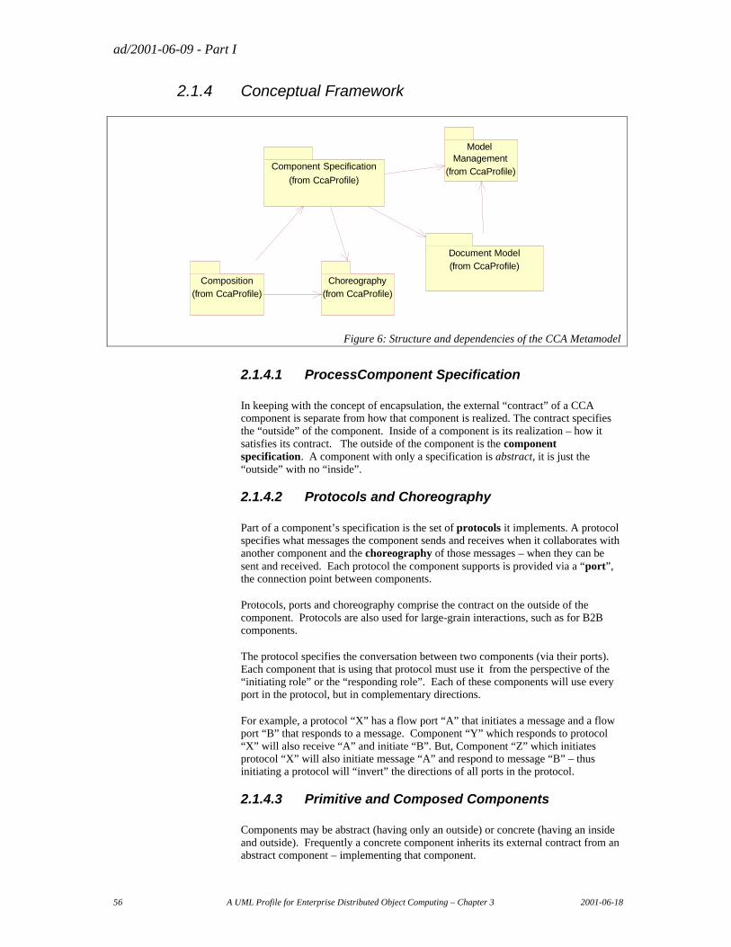
ad/2001-06-09 - Part I
56 A UML Profile for Enterprise Distributed Object Computing – Chapter 3 2001-06-18
2.1.4 Conceptual Framework
Document Model(from CcaProfile)
Component Specification
(from CcaProfile)
Composition(from CcaProfile)
Model Management
(from CcaProfile)
Choreography(from CcaProfile)
Figure 6: Structure and dependencies of the CCA Metamodel
2.1.4.1 ProcessComponent Specification
In keeping with the concept of encapsulation, the external “contract” of a CCA component is separate from how that component is realized. The contract specifies the “outside” of the component. Inside of a component is its realization – how it satisfies its contract. The outside of the component is the component specification. A component with only a specification is abstract, it is just the “outside” with no “inside”.
2.1.4.2 Protocols and Choreography
Part of a component’s specification is the set of protocols it implements. A protocol specifies what messages the component sends and receives when it collaborates with another component and the choreography of those messages – when they can be sent and received. Each protocol the component supports is provided via a “port”, the connection point between components.
Protocols, ports and choreography comprise the contract on the outside of the component. Protocols are also used for large-grain interactions, such as for B2B components.
The protocol specifies the conversation between two components (via their ports). Each component that is using that protocol must use it from the perspective of the “initiating role” or the “responding role”. Each of these components will use every port in the protocol, but in complementary directions.
For example, a protocol “X” has a flow port “A” that initiates a message and a flow port “B” that responds to a message. Component “Y” which responds to protocol “X” will also receive “A” and initiate “B”. But, Component “Z” which initiates protocol “X” will also initiate message “A” and respond to message “B” – thus initiating a protocol will “invert” the directions of all ports in the protocol.
2.1.4.3 Primitive and Composed Components
Components may be abstract (having only an outside) or concrete (having an inside and outside). Frequently a concrete component inherits its external contract from an abstract component – implementing that component.
ad/2001-06-09 - Part I
2001-06-18 A UML Profile for Enterprise Distributed Object Computing – Chapter 3 57
There may be any number of implementations for an ProcessComponent and various ways to “bind” the correct implementation when a component is used.
The two basic kinds of concrete components are:
• primitive components – those that are built with programming languages or by wrapping legacy systems.
• Composed Components – Components that are built from other components; these use other components to implement the new components functionality. Composed components are defined using a composition.
2.1.4.4 Composition
Compositions define how components are used. Inside of a composition components are used, configured and connected. This connected set of component usages implements the behavior of the composition in terms of these other components – which may be primitive, composed or abstract components.
Compositions are used to build composed components out of other components and to describe community processes – how a set of large grain components works together for some purpose. Components used in a community process represent the roles of that process.
Central to compositions are the connections between components, values for configuration properties and the ability to bind concrete components to a component usage.
2.1.4.5 Document & Information Model
The information that flows between components is described in a Document Model, the structure of information exchanged. The document model also forms the basis for information entities and a generic information model. The information model is acted on by CCA ProcessComponents (see the Entities profile, Section 3, below).
2.1.4.6 Model Management
To help organize the elements of a CCA model a “package” structure is used exactly as it is used in UML. Packages provide a hierarchical name space in which to define components and component artifacts. Model elements that are specific to a process, protocol or component may also be nested within these, since they also act as packages.
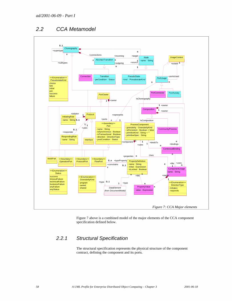
ad/2001-06-09 - Part I
58 A UML Profile for Enterprise Distributed Object Computing – Chapter 3 2001-06-18
2.2 CCA Metamodel
DirectionType
- initiates- responds
<<Enumeration>>
MultiPortProtocolPort
<<boundary>>
RespondingRole
- name : String
InitiatingRole
- name : String
Protocol
1+uses
1
0..1
1
+responder0..1
1
0..1
1+initiator
0..1
1
Transition
- preCondit ion : Status
PortActivityPortConnector
DataElement(from DocumentModel)
FlowPort<<boundary>>
0..1
n
+type 0..1
n
ProcessComponent
- granularity : GranularityKind- isPersistent : Boolean = false- primitiveKind : String = ""- primitiveSpec : String
Composition
ContextualBinding
1
n
+owner1
+bindingsn
n1
n
+bindsTo1
PropertyDefinition
- name : String- initial : Expression- isLocked : Boolean
1
n
+type1
n
0..1
0..n +typeProperty
0..1+constrains
0..n
1
n
+component 1
+properties n
ComponentUsage
name : String
n
1
n
+uses
1
Uses
n
1
+usesn
+owner1
n
1
n
+fills1
PropertyValue
- value : Expression
n
1
n
+fills1
1
n
+owner
1
n
OperationPort<<boundary>>
Connection PseudoState
- kind : PseudostateKind
Node
- name : StringAbstractTransition
n 1
+outgoing
n
+source
1
n 1
+incoming
n
+target
1
Choreography
nn
n
+connections
n
n
0..1
+subtypes
n
+supertype
0..1
CommunityProcess
Status
successtimeoutFailuretechnicalFailurebusinessFailureanyFailureanyStatus
<<Enumeration>>
PseudostateKind
choiceforkinitialjoinsuccessfailure
<<Enumeration>>
Interface
PortOwner
Port
- name : String- isSynchronous : Boolean- isTransactional : Boolean- direction : DirectionType- postCondition : Status
<<boundary>>
n
1
+ports n
+owner1
UsageContext
PortUsage
1
n
+represents
1
n
1
n
+extent 1
+portsUsed
n
IsComposition
IsChoreography
GranularityKind
- program- owned- shared
<<Enumeration>>
Figure 7: CCA Major elements
Figure 7 above is a combined model of the major elements of the CCA component specification defined below.
2.2.1 Structural Specification
The structural specification represents the physical structure of the component contract, defining the component and its ports.
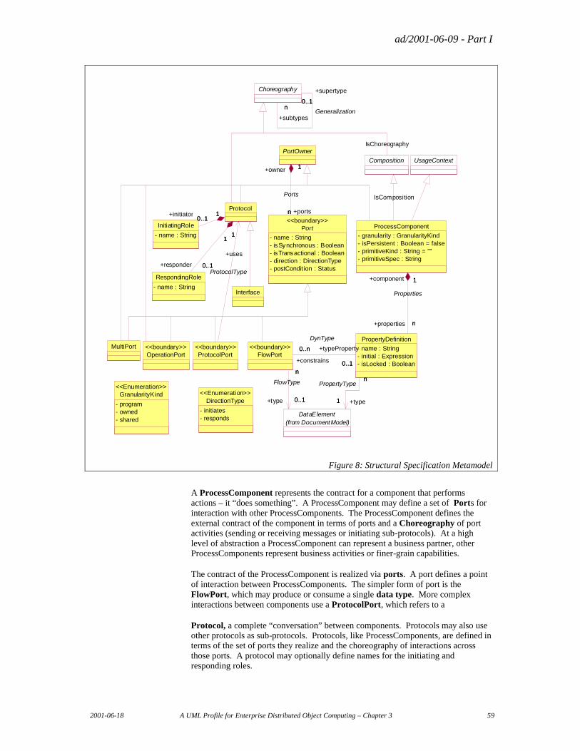
ad/2001-06-09 - Part I
2001-06-18 A UML Profile for Enterprise Distributed Object Computing – Chapter 3 59
DirectionType
- initiates- responds
<<Enumeration>>
Port
- name : String- isSynchronous : Boolean- isTransactional : Boolean- direction : DirectionType- postCondit ion : Status
<<boundary>>
PortOwner
n
1
+portsn
+owner 1
Ports
ProtocolPort<<boundary>>
RespondingRole
- name : String
InitiatingRole
- name : String
Protocol
1
+uses
1
ProtocolType0..1
1
+responder 0..1
1
0..11+initiator
0..11
DataElement(from DocumentModel)
FlowPort<<boundary>>
0..1
n
+type 0..1
n
FlowType
ProcessComponent
- granularity : GranularityKind- isPersistent : Boolean = false- primitiveKind : String = ""- primitiveSpec : String
PropertyDefinition
- name : String- initial : Expression- isLocked : Boolean
1
n
+type1
nPropertyType
0..1
0..n +typeProperty
0..1+constrains
0..n
DynType
1
n
+component 1
+properties n
Properties
MultiPort
Composition
Choreography
n0..1
+subtypes
nGeneralization
+supertype
0..1
IsChoreography
OperationPort<<boundary>>
Interface
UsageContext
IsComposition
GranularityKind
- program- owned- shared
<<Enumeration>>
Figure 8: Structural Specification Metamodel
A ProcessComponent represents the contract for a component that performs actions – it “does something”. A ProcessComponent may define a set of Ports for interaction with other ProcessComponents. The ProcessComponent defines the external contract of the component in terms of ports and a Choreography of port activities (sending or receiving messages or initiating sub-protocols). At a high level of abstraction a ProcessComponent can represent a business partner, other ProcessComponents represent business activities or finer-grain capabilities.
The contract of the ProcessComponent is realized via ports. A port defines a point of interaction between ProcessComponents. The simpler form of port is the FlowPort, which may produce or consume a single data type. More complex interactions between components use a ProtocolPort, which refers to a
Protocol, a complete “conversation” between components. Protocols may also use other protocols as sub-protocols. Protocols, like ProcessComponents, are defined in terms of the set of ports they realize and the choreography of interactions across those ports. A protocol may optionally define names for the initiating and responding roles.
ad/2001-06-09 - Part I
60 A UML Profile for Enterprise Distributed Object Computing – Chapter 3 2001-06-18
ProcessComponents may have Property Definitions. A property definition defines a configuration parameter of the component, which can be set, when the component is used.
The behavior of a ProcessComponent may be further specified by its composition, the composition shows how other components are used to define and implement the composite component. The specification of the ProcessComponent and protocol may include Choreography to sequence the actions of multiple ports and their associated actions. The actions of each port may be Choreographed. Composition and Choreography are defined in their own sections.
A ProcessComponent may have a supertype (derived from Choreography). One common use of supertype is to place abstract ProcessComponents within compositions and then produce separate realizations of those components as subtype composite or primitive components, which can then be substituted for the abstract components when the composition is used, or even at runtime.
An Interface represents a standard object interface. It may contain OperationPorts, representing call-return semantics, and FlowPorts – representing one-way operations.
A MultiPort is a grouping of ports whose actions are tied together. Information must be available on all sub-ports of the MultiPort for any action to occur within an attached component.
An OperationPort defines a port which realizes a typical request/response operation and allows ProcessComponents to represent both document oriented (FlowPort) and method oriented (OperationPort) subsystems.
2.2.1.1 ProcessComponent
Semantics
A ProcessComponent represents an active processing unit – it does something. A ProcessComponent may realize a set of Ports for interaction with other ProcessComponents and it may be configured with properties.
Each ProcessComponent defines a set of ports for interaction with other ProcessComponents and has a set of properties that are used to configure the ProcessComponent when it is used.
The order in which actions of the Process Component’s ports do something may be specified using Choreography. The choreography of a ProcessComponent specifies the external temporal contact of the ProcessComponent (when it will do what) based on the actions of its ports and the ports in protocols of its ports.
UML base element(s) in the Profile and Stereotype
Classifier Stereotyped as <<ProcessComponent>>
Fully Scoped name
ECA::CCA::ProcessComponent
Owned by
Package
ad/2001-06-09 - Part I
2001-06-18 A UML Profile for Enterprise Distributed Object Computing – Chapter 3 61
Extends
Composition (indicating that the ProcessComponent may be composed of other ProcessComponents and that its ports may be choreographed.)
Package (Indicating that a ProcessComponent may own the specification of other elements)
UsageContext (Indicating that the ProcessComponent may be the context for PortUsages representing the activities of its ports.).
Properties
Granularity
A GranularityKind which defines the scope in which the component operates. The values may be:
• Program – the component is local to a program instance (default)
• Owned – the component is visible outside of the scope of a particular program but dedicated to a particular task or session which controls its life cycle.
• Shared – the component is generally visible to external entities via some kind of distributed infrastructure.
Specializations of CCA may define additional granularity values.
UML Representation
Tagged value
isPersistent
Indicates that the component stores session specific state across interactions. The mechanisms for management of sessions are defined outside of the scope of CCA.
UML Representation
Tagged value
primitiveKind
Components implementation includes additional implementation semantics defined elsewhere, perhaps in an action language or programming language. If the component has an implementation specification primitiveKind specifies the implementation specific type, normally the name of a programming language. If primitive kind is blank, the composition is the full specification of the components implantation – the component is not primitive.
UML Representation
Tagged value
ad/2001-06-09 - Part I
62 A UML Profile for Enterprise Distributed Object Computing – Chapter 3 2001-06-18
primitiveSpec
If primitiveKind has a value, primitiveSpec identifies the location of the implementation. The syntax of primitiveKind is implementation specific.
UML Representation
Tagged value
Related elements
Ports (via “PortOwner”)
“Ports” is the set of Ports on the ProcessComponent. Each port provides a connection point for interaction with other components or services and realizes a specific protocol. The protocol may be simple and use a “FlowPort” or the protocol may be complex and use a “ProtocolPort” or an “OperationPort”. If allowed by its protocol, a port may send and receive information.
UML Representation
Required Aggregation Association from Port (Ports)
Supertype (zero or one) , Subtypes (any number)
A ProcessComponent may inherit specification elements (ports, properties & states (from Choreography) from a supertype. That supertype must also be a ProcessComponent. A subtype component is bound by the contract of its supertypes but it may add elements, override property values and restrict referenced types.
A component may be substituted by a subtype of that component.
UML Representation
Generalization
Properties (Any number)
To make a component capable of being reused in a variety of conditions it is necessary to be able to define and set properties of that component. Properties represents the list of properties defined for this component.
UML Representation
Classifier.feature referencing an attribute.
Constraints
A process component may only inherit from another process component.
ad/2001-06-09 - Part I
2001-06-18 A UML Profile for Enterprise Distributed Object Computing – Chapter 3 63
2.2.1.2 Port
Semantics
A port realizes a simple or complex conversation for a ProcessComponent or protocol. All interactions with a ProcessComponent are done via one of its ports.
When a component is instantiated, each of its ports is instantiated as well, providing a well-defined connection point for other components.
Each port is connected with collaborative components that speak the same protocol. Multi-party conversions are defined by components using multiple ports, one for each kind of party.
Business Example: Flight reservation Port
UML base element(s) in the Profile and Stereotype
Class (abstract)
Fully Scoped name
ECA::CCA::Port
Owned by
ProcessComponent or Protocol via PortOwner
Extends
None
Properties
isTransactional
Indicates that interactions with the component are transactional & atomic (in most implementations this will require that a transaction be started on receipt of a message). Non-transactional components either maintain no state or must execute within a transactional component. The mechanisms for management of transactions are defined outside of the scope of CCA.
UML Representation
Tagged Value
isSynchronous
A port may interact synchronously or asynchronously. A port that is marked as synchronous is required to interact using synchronous messages and return values.
ad/2001-06-09 - Part I
64 A UML Profile for Enterprise Distributed Object Computing – Chapter 3 2001-06-18
UML Representation
Tagged Value
name
The name of the port. The name will, by default, be the same as the name of the protocol role or document type it realises.
UML Representation
ModelElement::name
Direction
Indicates that the port will either initiate or respond to the related type. An initiating port will send the first message. Note that by using ProtocolPorts a port may be the initiator of some protocols and the responder to others. The values of DirectionKind may be:
Initiates – this port will initiate the conversation by sending the first message.
Responds – this port will respond to the initial message and (potentially) continue the conversation.
UML Representation
Tagged Value and stereotype of “Owner” relation.
PostCondition
The status of the conversation indicated by the use of this port. This status may be queried in the postCondition of a transition.
UML Representation
Tagged Value
Related elements
“Owner” ProcessComponent or Protocol (Exactly One via PortOwner)
A Port specifies the realization of protocol by a ProcessComponent. This relation specifies the ProcessComponent that realizes the protocol.
UML Representation
Required aggregate association (Ports). This association will have a stereotype of “initiates” or “responds” to indicate “direction”.
ad/2001-06-09 - Part I
2001-06-18 A UML Profile for Enterprise Distributed Object Computing – Chapter 3 65
Constraints
None
2.2.1.3 FlowPort
Semantics
A Flow Port is a port which defines a data flow in or out of the port on behalf of the owning component or protocol.
UML base element(s) in the Profile and Stereotype
Class stereotyped as <<FlowPort>>
Fully Scoped name
ECA::CCA::FlowPort
Owned by
PortOwner
Extends
Port
Properties
None
Related elements
type
The type of data element that may flow into our out of the port.
UML Representation
Required relation
TypeProperty
The type of information sent or received by this port as determined by a configurable property. The expression must return a valid type name. This is used to build generic components that may have the type of their ports configured. If type and typeProperty are both set then the property expression must return the name of a subtype of type.
ad/2001-06-09 - Part I
66 A UML Profile for Enterprise Distributed Object Computing – Chapter 3 2001-06-18
UML Representation
Tagged value containing the name of the property attribute.
Constraints
None
2.2.1.4 ProtocolPort
Semantics
A protocol port is a port which defines the use of a protocol A protocol port is used for potentially complex two-way interactions between components, such as is common in B2B protocols. Since a protocol has two “roles” (the initiator and responder), the direction is used to determine which role the protocol port is taking on.
UML base element(s) in the Profile and Stereotype
Class stereotyped as <<ProtocolPort>>
Fully Scoped name
ECA::CCA::ProtocolPort
Owned by
PortOwner
Extends
Port
Properties
None
Related elements
uses
The protocol to use, which becomes the specification of this port’s behavior.
UML Representation
Generalization – the ProtocolPort inherits the Protocol.
Constraints
None
ad/2001-06-09 - Part I
2001-06-18 A UML Profile for Enterprise Distributed Object Computing – Chapter 3 67
2.2.1.5 OperationPort
Semantics
An operation port represents the typical call/return pattern of an operation. The OperationPort is a PortOwner which is constrained to contain only flow ports, exactly one of which must have its direction set to “initiates”. The other “responds” ports will be the return values of the operation.
UML base element(s) in the Profile and Stereotype
Operation (no stereotype)
Note1: The type of the “initiates” flow port will be the signature of the operation. Each attribute of the type will be one parameter of the operation.
Note2: Owned flow ports of postCondition==Success and direction==”responds” will be a return value for the operation. All other flow ports where direction==”responds” will correspond to an exception.
Fully Scoped name
ECA::CCA::OperationPort
Owned by
PortOwner (Protocol or ProcessComponent)
Extends
Port and PortOwner
Properties
None
Related elements
Ports (Via PortOwner)
The flow ports representing the call and returns.
UML Representation
Initiates ports – signature of the operation
Responds ports – return values of the operation.
Constraints
As a PortOwner, the OperationPort:
ad/2001-06-09 - Part I
68 A UML Profile for Enterprise Distributed Object Computing – Chapter 3 2001-06-18
• May only contain FlowPorts
• Must contain exactly one flow port with direction set to “initiates” (the call)
2.2.1.6 MultiPort
Semantics
A MultiPort combines a set of ports which are behaviourally related. Each port owned by the MultiPort will “buffer” information sent to that port until all the ports within the MultiPort have received data, at this time all the ports will send their data.
UML base element(s) in the Profile and Stereotype
Class stereotyped as <<MultiPort>>
Fully Scoped name
ECA::CCA::MultiPort
Owned by
PortOwner
Extends
Port & PortOwner
Properties
None
Related elements
Ports (Via PortOwner)
The flow ports owned by the MultiPort.
UML Representation
Required aggregation association
Constraints
Owned ports will not forward data until all sub-ports have received data.
ad/2001-06-09 - Part I
2001-06-18 A UML Profile for Enterprise Distributed Object Computing – Chapter 3 69
2.2.1.7 Protocol
Semantics
A protocol defines a type of conversation between two parties, the initiator and responder. One protocol role is the initiator of the conversation and the other the responder. However, after the conversation has been initiated, individual messages and sub-protocols may by initiated by either party.
Within the protocol are sub-ports . Each port contained by a protocol defines a sub-action of that protocol until, ultimately, everything is defined in terms of FlowPorts.
A Protocol is also a choreography, indicating that activities of its ports (and, potentially their sub-ports) may be sequenced using an activity graph.
A protocol must be used by a ProtocolPort to become active.
The protocol specifies the conversation between two ProcessComponents (via their ports). Each component that is using that protocol must use it from the perspective of the “initiating role” or the “responding role”. Each of these components will use every port in the protocol, but in complementary directions.
For example, a protocol “X” has a flow port “A” that initiates a message and a flow port “B” that responds to a message. Component “Y” which responds to protocol “X” will also receive “A” and initiate “B”. But, Component “Z” which initiates protocol “X” will initiate message “A” and respond to message “B” – thus initiating a protocol will “invert” the directions of all ports in the protocol.
UML base element(s) in the Profile and Stereotype
Class stereotyped as <<Protocol>>
Fully Scoped name
ECA::CCA::Protocol
Owned by
Package
Extends
Choreography – Indicating that the contract of the protocol includes a sequencing of the port activities.
Package – Indicating that the protocol may contain the specification of other model elements (Most probably other protocols or documents).
Properties
None
ad/2001-06-09 - Part I
70 A UML Profile for Enterprise Distributed Object Computing – Chapter 3 2001-06-18
Related elements
Ports (Via PortOwner)
The ports which define the sub-actions of the protocol. For example, a “callReturn” protocol may have a “call” FlowPort and a “return” FlowPort.
UML Representation
Required aggregate association
Initiator
The role which sends the first message in the protocol. Note that this is optional, in which case the initiating role name will be “Initiator”.
UML Representation
Required relation
Responder
The role which receives the first message in the protocol. Note that this is optional, in which case the responding role name will be “Responder”.
UML Representation
Required relation
Constraints
None
2.2.1.8 Interface
Semantics
An interface is a protocol constrained to match the capabilities of the typical object interface. It is constrained to only contain OperationPorts and FlowPorts and all of its ports must respond to the interaction (making interfaces one-way).
Each OperationPort or FlowPort in the Interface will map to a method. A ProtocolPort which initiates the Interface will call the interface. A ProtocolPort which Responds will implement the interface.
UML base element(s) in the Profile and Stereotype
Classifier (Usually Interface, but any classifier will do)
Fully Scoped name
ECA::CCA::Interface
ad/2001-06-09 - Part I
2001-06-18 A UML Profile for Enterprise Distributed Object Computing – Chapter 3 71
Owned by
Package
Extends
Protocol
Properties
None
Related elements
Ports (Via Protocol & PortOwner)
The ports which define the sub-actions of the protocol. For example, a “callReturn” protocol may have a “call” flowport and a “return” port.
Initiator (Via Protocol)
The role which calls the interface. Note that this is optional, in which case the initiating role name will be “Initiator”. roles.
Responder (Via Protocol)
The role which implements the interface. Note that this is optional, in which case the responding role name will be “Responder”.
Constraints
• The Ports related by the “Ports” association must;
• be of type OperationPort or FlowPort.
• have direction == ”responds”.
2.2.1.9 InitiatingRole
Semantics
The role of the protocol which will send the first message.
UML base element(s) in the Profile and Stereotype
Class stereotyped as <InitiatingRole>

ad/2001-06-09 - Part I
72 A UML Profile for Enterprise Distributed Object Computing – Chapter 3 2001-06-18
Fully Scoped name
ECA::CCA::InitiatingRole
Owned by
Protocol
Extends
None
Properties
name
Role name
UML Representation
ModelElement::name
Related elements
Protocol
The protocol for which the role is being defined.
UML Representation
Required relation
Constraints
None
2.2.1.10 RespondingRole
Semantics
The role in the protocol which will receive the first message.
UML base element(s) in the Profile and Stereotype
Class stereotyped as <RespondingRole>
Fully Scoped name
ECA::CCA::RespondingRole
ad/2001-06-09 - Part I
2001-06-18 A UML Profile for Enterprise Distributed Object Computing – Chapter 3 73
Owned by
Protocol
Extends
None
Properties
Name
UML Representation
ModelElement::name
Related elements
Protocol
The protocol for which the role is being defined.
UML Representation
Required relation
Constraints
None
2.2.1.11 PropertyDefinition
Semantics
To allow for greater flexibility and reuse, ProcessComponents may have properties which may be set when the ProcessComponent is used. A PropertyDefinition defines that such a property exists, its name and type.
UML base element(s) in the Profile and Stereotype
Attribute (No stereotype)
Fully Scoped name
ECA::CCA::PropertyDefinition
Owned by
ProcessComponent
ad/2001-06-09 - Part I
74 A UML Profile for Enterprise Distributed Object Computing – Chapter 3 2001-06-18
Extends
None
Properties
name
Name of the property being modelled
UML Representation
ModelElement:name
initial
An expression indicating the initial & default value.
UML Representation
Attribute::initialValue
isLocked
The property may not be changed.
UML Representation
StructuralFeature::changeability
Related elements
component
The owning component
UML Representation
ModelElement::namespace
type
The type of the property
UML Representation
StructuralFeature::type
Constraints
If the “constrains” relation contains any links;
ad/2001-06-09 - Part I
2001-06-18 A UML Profile for Enterprise Distributed Object Computing – Chapter 3 75
• The PropertyValue must contain the fully qualified name of a DataElement.
PortOwner
Semantics
An abstract meta-class used to group the meta-classes that may own ports: Process component, Protocol, OperationPort and MultiPort.
UML base element(s) in the Profile and Stereotype
None (Abstract)
Fully Scoped name
ECA::CCA::PortOwner
Owned by
None
Extends
None
Related elements
ports
The owned ports
UML Representation
Required relation
Constraints
None
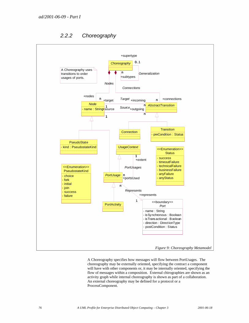
ad/2001-06-09 - Part I
76 A UML Profile for Enterprise Distributed Object Computing – Chapter 3 2001-06-18
2.2.2 Choreography
A Choreography uses transitions to order usages of ports.
Status
- success- timeoutFailure- technicalFailure- businessFailure- anyFailure- anyStatus
<<Enumeration>>
PseudoState
- kind : PseudostateKind
Transition
- preCondit ion : Status
PortActivity
Connection
PseudostateKind
- choice- fork- initial- join- success- failure
<<Enumeration>>
UsageContext
Port
- name : String- isSynchronous : Boolean- isTransactional : Boolean- direction : Direct ionType- postCondition : Status
<<boundary>>
PortUsage
1
n
+extent1
+portsUsedn
PortUsages
1
n
+represents
1
n
Represents
Node
- name : StringAbstractTransition
n1
+outgoing
n
+source
1
Sourcen1
+incoming
n
+target
1
Target
Choreography
n+nodes
n
Nodes
n +connectionsn
Connections
n
0..1
+subtypesn Generalization
+supertype
0..1
Figure 9: Choreography Metamodel
A Choreography specifies how messages will flow between PortUsages. The choreography may be externally oriented, specifying the contract a component will have with other components or, it may be internally oriented, specifying the flow of messages within a composition. External chirographies are shown as an activity graph while internal choreography is shown as part of a collaboration. An external choreography may be defined for a protocol or a ProcessComponent.
ad/2001-06-09 - Part I
2001-06-18 A UML Profile for Enterprise Distributed Object Computing – Chapter 3 77
A Choreography uses Connections and transitions to order port messages as a state machine. Each “node” in the choreography must refer to a state or a port usage.
Choreography is an abstract capability that is inherited by ProcessComponents and protocols.
Initial, interim and terminating states are known as a “PseudoState” as defined in UML. CCA adds the pseudo states for success and failure end-states.
Ordering is controlled by connections between nodes (state and port usage being a kind of node). Transitions specify flow of control that will occur if the conditions (Precondition) are met. Transitions between port activities specify what should happen (contractually), while Connections between PortConnections specify what will happen at runtime.
2.2.2.1 Choreography
Semantics
An abstract class inherited by protocol and ProcessComponent which owns nodes and AbstractTransitions. A choreography specifies the ordering of port activities.
UML base element(s) in the Profile and Stereotype
Choreography - State Machine stereotyped as <<choreography>>: (context references classifier)
Fully Scoped name
ECA::CCA::Choreography
Owned by
None
Extends
None
Properties
None
Related elements
Nodes
The states and port usages to be choreographed.
UML Representation
PseudoState - StateMachine.top
ad/2001-06-09 - Part I
78 A UML Profile for Enterprise Distributed Object Computing – Chapter 3 2001-06-18
PortActivity ::SubmachineState
AbstractTransitions
The connections and transitions between nodes.
UML Representation
Transition: StateMachine:transition
Connection: Collaboration::AssociationRole
Supertype (zero or one) , Subtypes (any number)
A ProcessComponent, protocol or CommunityProcess may inherit specification elements (ports, properties & states (from Choreography) from a supertype. That supertype must also be a ProcessComponent. A subtype component is bound by the contract of its supertypes but it may add elements, override property values and restrict referenced types.
A component may be substituted by a subtype.
Constraints: The subtype-supertype relation may only exist between elements of the same meta-type. A ProcessComponent may only inherit from another ProcessComponent. A Protocol may only inherit from another Protocol and a CommunityProcess may only inherit from another CommunityProcess.
UML Representation
Generalization of classifier related by context.
Node
Semantics
Node is an abstract element that specifies something that can be the source and/or target of a connection or transition and thus ordered within the choreographed process. The nodes that do “real work” are PortUsages.
UML base element(s) in the Profile and Stereotype
None (abstract)
Fully Scoped name
ECA::CCA::Node
Owned by
Choreography
ad/2001-06-09 - Part I
2001-06-18 A UML Profile for Enterprise Distributed Object Computing – Chapter 3 79
Extends
None
Properties
name
UML Representation
ModelElement:name
Related elements
Choreography
The owning protocol or ProcessComponent.
UML Representation
See Choreogrphy
Incoming
Transitions that cause this node to become active.
UML Representation
Transition: State:incoming
Connection: AssociationEndRole
outgoing
Nodes that may become active after this node completes.
UML Representation
State: outgoing
Connection: AssociationEndRole
Constraints
None
2.2.2.2 AbstractTransition
Semantics
The flow of data and/or control between two nodes.
ad/2001-06-09 - Part I
80 A UML Profile for Enterprise Distributed Object Computing – Chapter 3 2001-06-18
UML base element(s) in the Profile and Stereotype
None - abstract
Fully Scoped name
ECA::CCA::AbstractTransition
Owned by
Choreography
Extends
None
Properties
None
Related elements
Choreography
The owning choreography.
UML Representation
See Choreography
Source
The node which is transferring control and/or data.
UML Representation
Connection: AssociationEndRole
Transition: Transition:source
Target
The node to which data and/or control will be transferred.
UML Representation
Connection: AssociationEndRole
Transition: Transition:target
ad/2001-06-09 - Part I
2001-06-18 A UML Profile for Enterprise Distributed Object Computing – Chapter 3 81
Constraints
The source and target nodes associated with the AbstractTransition must be owned by the same choreography as the AbstractTransition.
2.2.2.3 Transition
Semantics
The contractual specification that the related nodes will activate based on the ordering imposed by the set of transitions between nodes. Transitions, which declare a contract may be differentiated from Connections which realise a contract.
UML base element(s) in the Profile and Stereotype
Transition (No Stereotype)
Fully Scoped name
ECA::CCA::Transition
Owned by
Choreography
Extends
AbstractTransition
Properties
preCondition
A constraint on the transition such that it may only fire if the prior PortUsage terminated with the referenced condition.
UML Representation
Transition:guard
Related elements
Choreography (Via AbstractTransition)
The owning choreography.
UML Representation
See Choreography
ad/2001-06-09 - Part I
82 A UML Profile for Enterprise Distributed Object Computing – Chapter 3 2001-06-18
Source
The node which is transferring control and/or data.
UML Representation
Transition: Transition:source
Target
The node to which data and/or control will be transferred.
UML Representation
Transition: Transition:target
Constraints
A transition may not connect PortConnectors.
2.2.2.4 PortUsage
Semantics
The usage of a port as part of a choreography.
UML base element(s) in the Profile and Stereotype
None (Abstract)
Fully Scoped name
ECA::CCA::PortUsage
Owned by
Choreography
Extends
Node & Usage Context
Properties
None
ad/2001-06-09 - Part I
2001-06-18 A UML Profile for Enterprise Distributed Object Computing – Chapter 3 83
Related elements
extent
The component, component usage or PortUsage to which the PortUsage is attached.
If the extent is a ComponentUsage the PortUsage must be a PortConnector for a port of the underlying ProcessComponent. This allows Connections between components being used within a composition.
If the extent is a PortUsage the PortUsage must represent a ProtocolPort which owns the represented usage. This allows the choreography of nested ports.
If the extent is a ProcessComponent the usage represents a port on the ProcessComponent and that ProcessComponent must be the composition owning both the port and the port usage. This allows Connections and transitions to be connected to the external ports of a component.
UML Representation
State machine: Owner of state machine
Collaboration: Association Role
Represents
The port which the PortUsage uses.
UML Representation
State machine: tagged value
Collaboration: ClassifierRole::base
Constraints
None
2.2.2.5 UsageContext
Semantics
When a port is used within a choreography it must be used within some context. UsageContext represents an abstract supertype of all elements that may be the context of a port. These are;
• ProcessComponent – as the owner of port activities and port connectors.
• ComponentUsage – as the owner of port connectors, representing the use of each of the component’s ports.
• PortUsages – representing ports nested via protocols.
ad/2001-06-09 - Part I
84 A UML Profile for Enterprise Distributed Object Computing – Chapter 3 2001-06-18
UML base element(s) in the Profile and Stereotype
None (abstract)
Fully Scoped name
ECA::CCA::UsageContext
Owned by
None
Extends
None
Properties
None
Related elements
PortsUsed
Provides context for port usage
UML Representation
State machine: owned states
Collaboration: AssociationRole
Constraints
None
2.2.2.6 PortActivity
Semantics
Port activity is state, part of the “contract” of a ProcessComponent or protocol, specifying the activation of a port such the ordering of port activities can be choreographed with transitions. A PortActivity (used with transitions) defines the contract of the component while a PortConnector (used with Connections) specifies the realisation of a component’s actions in terms of other components.
UML base element(s) in the Profile and Stereotype
CompositeState Stereotyped as <<PortActivity>>
ad/2001-06-09 - Part I
2001-06-18 A UML Profile for Enterprise Distributed Object Computing – Chapter 3 85
Fully Scoped name
ECA::CCA::PortActivity
Owned by
Protocol or ProcessComponent via Choreography
Extends
PortUsage
Properties
None
Related elements
None
Constraints
Port Activities may only be connected using transitions.
2.2.2.7 PseudoState
Semantics
PseudoState specifies starting, ending or intermediate states in the choreography of the contract of a protocol or ProcessComponent.
UML base element(s) in the Profile and Stereotype
Depending on value of kind:
• Success – FinalState Stereotyped as <<success>>
• Failure – FinalState Stereotyped as <<failure>>
• All Others - PseudoState (no stereotype) with kind set to same value.
Fully Scoped name
ECA::CCA::PseudoState
Owned by
Choreography
ad/2001-06-09 - Part I
86 A UML Profile for Enterprise Distributed Object Computing – Chapter 3 2001-06-18
Extends
Node
Properties
Kind ; PseudostateKind
choice Splits an incoming transition into several disjoint outgoing transition. Each outgoing transition has a guard condition that is evaluated after prior actions on the incoming path have been completed. At least one outgoing transition must be enabled or the model is ill-formed.
fork Splits an incoming transition into several concurrent outgoing transitions. All the transitions fire together.
initial The default target of a transition to the enclosing composite state.
join Merges transitions from concurrent regions into a single outgoing transition. Join PseudoState will proceed after all its incoming Transition have triggered.
success The end-state indicating that the choreography ended in success.
failure The end-state indicating that the choreography ended in failure.
Related elements
None
Constraints
PseudoStates may only be connected using transitions.
2.2.3 Composition
Composition is an abstract capability that is used for ProcessComponents and for community processes. Compositions shows how a set of components can be used to define and perhaps to implement a process.
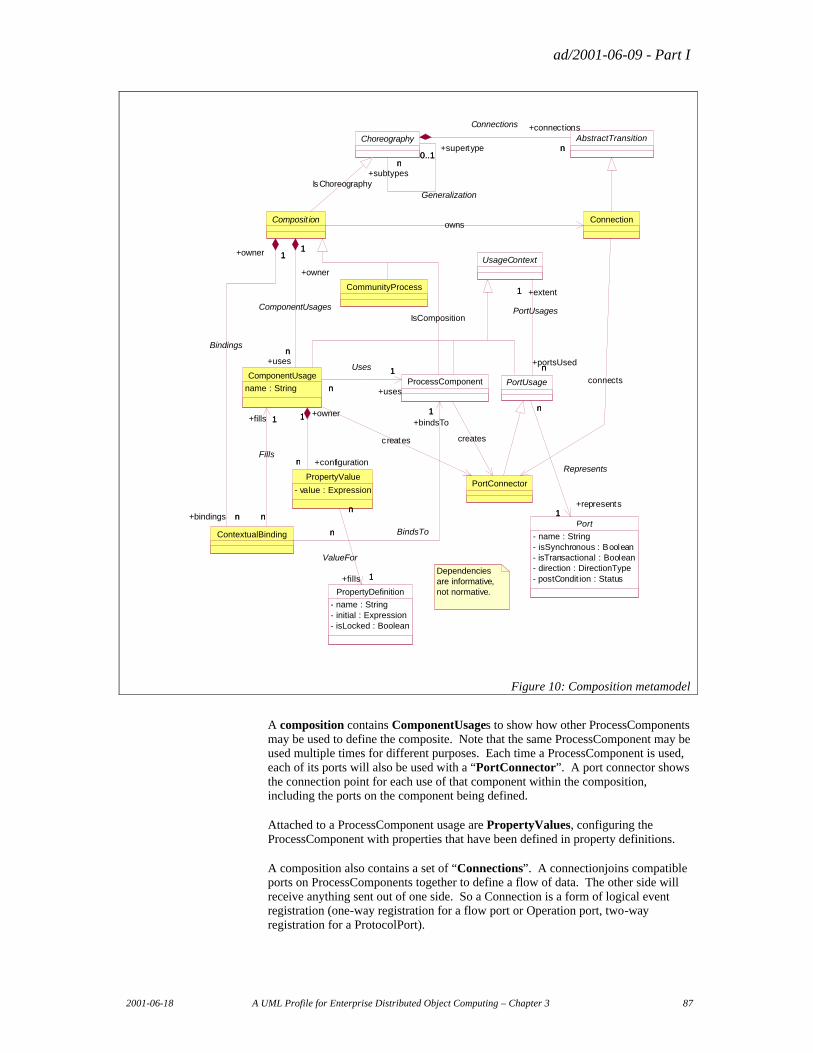
ad/2001-06-09 - Part I
2001-06-18 A UML Profile for Enterprise Distributed Object Computing – Chapter 3 87
PortConnector
Connection
Dependencies are informative, not normative.
UsageContext
Port
- name : String- isSynchronous : Boolean- isTransactional : Boolean- direction : DirectionType- postCondit ion : Status
PortUsage
1
n
+extent1
+portsUsedn
PortUsages
1
n
+represents1
n
Represents
ContextualBinding
Composit ionowns
1
n
+owner 1
+bindings n
Bindings
ProcessComponent
1
n
+bindsTo1
n BindsTo
creates
ComponentUsage
name : String
1
n
+fills 1
n
Fills
1
n
+owner
1
+usesn
ComponentUsages
creates
1
n +uses
1
n
Uses
PropertyValue
- value : Expression
n
1
+configurationn
+owner1
PropertyDefinition
- name : String- initial : Expression- isLocked : Boolean
n
1
n
+fills 1
ValueFor
CommunityProcess
AbstractTransitionChoreographyn
+connections
n
Connections
IsChoreography
n0..1
+subtypesn
Generalization
+supertype0..1
connects
IsComposition
Figure 10: Composition metamodel
A composition contains ComponentUsages to show how other ProcessComponents may be used to define the composite. Note that the same ProcessComponent may be used multiple times for different purposes. Each time a ProcessComponent is used, each of its ports will also be used with a “PortConnector”. A port connector shows the connection point for each use of that component within the composition, including the ports on the component being defined.
Attached to a ProcessComponent usage are PropertyValues, configuring the ProcessComponent with properties that have been defined in property definitions.
A composition also contains a set of “Connections”. A connectionjoins compatible ports on ProcessComponents together to define a flow of data. The other side will receive anything sent out of one side. So a Connection is a form of logical event registration (one-way registration for a flow port or Operation port, two-way registration for a ProtocolPort).
ad/2001-06-09 - Part I
88 A UML Profile for Enterprise Distributed Object Computing – Chapter 3 2001-06-18
A Contextual Binding allows realized ProcessComponents to be substituted for abstract ProcessComponents when a composition is used.
Compositions may be ProcessComponents or CommunityProcesses. CommunityProcess define a top-level process in terms of the roles played by process components representing actors in the process.
2.2.3.1 Composition
Semantics
Composition is an abstract class for CommunityProcesses or ProcessComponents. Compositions describe how instances of ProcessComponents (called ComponentUsages) are configured (with PropertyValues and ContextualBindings) and connected (with Connections) to implement the composed ProcessComponent or CommunityProcess.
UML base element(s) in the Profile and Stereotype
Collaboration (with represented classifier being the ProcessComponent or CommnityProcess being defined) – stereotyped as <<Composition>>
Fully Scoped name
ECA::CCA::Compsition
Owned by
None
Extends
Choreography
Properties
None
Related elements
bindings
ContextualBindings defined within the context of the composition.
UML Representation
ModelElement::clientDependency
uses
ComponentUsages defined within the context of the composition.
ad/2001-06-09 - Part I
2001-06-18 A UML Profile for Enterprise Distributed Object Computing – Chapter 3 89
UML Representation
Collaboration:: (Owned ClassifierRoles)
Connection (via choreography and AbstractTransition)
The flow of data and control between port connectors.
UML Representation
Collaboration:: ownedElement (Owned AssociationRoles)
PortConnector (via Choreography and nodes)
The port instances to be connected by Connections.
UML Representation
Collaboration:: (Owned ClassifierRoles)
Constraints
None
2.2.3.2 ComponentUsage
Semantics
A composition uses other ProcessComponents to define the process of the composition (a community process or ProcessComponent), “ComponentUsage” represents such a use of a component. The “uses” relation references the kind of component being used. Component Usage is part of the “inside” of a composed component.
The composition can be thought of as a template of ProcessComponent instances. Each component instance will have a “ComponentUsage” to say what kind of ProcessComponent it is, what its property values are and how it is connected to other ProcessComponents. A ComponentUsage will cause a ProcessComponent instance to be created at runtime (this instantiation may be real or virtual).
Each use of a ProcessComponent will carry with it a set of “portConnectors” which will be the connection points to other ProcessComponents.
UML base element(s) in the Profile and Stereotype
ClassifierRole Stereotyped as “ComponentUsage”
Fully Scoped name
ECA::CCA::ComponentUsage
ad/2001-06-09 - Part I
90 A UML Profile for Enterprise Distributed Object Computing – Chapter 3 2001-06-18
Owned by
Composition
Extends
UsageContext
Properties
Name
The name of the activity for which the component is being used.
UML Representation
ModelElement::name
Related elements
owner
The owning composition
UML Representation
ClassifierRole::(owning collaboration)
Uses
The type of ProcessComponent to use.
UML Representation
ClassifierRole::base
PortsUsed (Via UsageContext)
PortConnectors for each port on the used component.
UML Representation
AssociationRole
Constraints
None
ad/2001-06-09 - Part I
2001-06-18 A UML Profile for Enterprise Distributed Object Computing – Chapter 3 91
2.2.3.3 PortConnector
Semantics
The PortConnector provides a “connection point” for ComponentUsages within a composition and exposes the defined ports within the composition. The connections between PortConnectors are made with Connections.
PortConnections are “implied” by other model elements and will normally be created by design tools. PortConnections should be created as follows:
• For each ComponentUsage there will be exactly one PortUsage for each port defined for the ProcessComponent being used.
• For each port on the ProcessComponent being defined there will be exactly one PortUsage to support Connections to and from “outside” ports.
• For each port within a protocol, OperationPort or MultiPort created for one of the above two reasons, a PortConnector may be created for each contained port. This allows Connections to be connected to finer grain elements, such as Connections within a protocol.
In summary, the “ProcessComponent” / “Port” pattern which defines the components external interface is essentially replicated in the “ComponentUsage” / “portConnector” part of the composition. Each time a component is used, each of its ports is used as well. Sub-ports of protocols also become PortConnectors.
UML base element(s) in the Profile and Stereotype
ClassifierRole stereotyped as PortConnector
Fully Scoped name
ECA::CCA::PortConnector
Owned by
Composition
Extends
PortUsage
Properties
None
Related elements
Represents (via PortUsage)
The port of which this is a port.
ad/2001-06-09 - Part I
92 A UML Profile for Enterprise Distributed Object Computing – Chapter 3 2001-06-18
Contexts (via PortUsage)
The associated owner of the port.
Incoming and Outgoing Connections (Via PortUsage and Node)
The Connections.
Constraints
PortConnectors are intended to be connected with Connections, Transitions may not be connected to a PortConnector
2.2.3.4 Connection
Semantics
A Connection connects two PortConnectors within a composition. Each port can produce and/or consume message events. The connection logically registers each port connector as a listener to the other, effectively making them collaborators.
A component only declares that given ports will produce or consume given messages, it doesn’t not know “who” will be on the other side. The composition shows how a ProcessComponent will be used within a context and thus how it will be connected to other components within that context. A Connection connects exactly two PortConnectors.
Connections may be distinguished from transitions in that Connections specify what events will flow between ProcessComponents while transitions specify the contract of port ordering.
UML base element(s) in the Profile and Stereotype
AssociationRole optionally stereotyped as <<Connection>>
Note: A Connection to a port contained by an interface will be represented by an operation, not a classifier. In this case the association role is directed to the ProtocolPort realising the interface and a message attached with a call action referencing the operation in question.
Fully Scoped name
ECA::CCA::Connection
Owned by
Composition
Extends
AbstractTransition
ad/2001-06-09 - Part I
2001-06-18 A UML Profile for Enterprise Distributed Object Computing – Chapter 3 93
Properties
None
Related elements
Source and Target PortConnectors (Via PortUsage, Node & AbstractTransition)
The PortConnectors between which the Connection is being defined.
Constraints
• The source and target nodes of a Connection must be PortConnectors.
• The source and target nodes must be port connectors owned by the same composition as the Connection.
2.2.3.5 PropertyValue
Semantics
To be useful in a variety of conditions, a ProcessComponent may have configuration properties –which are defined by a PropertyDefinition. When the component is used in a ComponentUsage those properties values may be set using a PropertyValue. These values will be used to construct or configure a component instance.
A PropertyValue should be included whenever the default property value is not correct in the given context.
UML base element(s) in the Profile and Stereotype
Constraint stereotyped as <PropertyValue>
Fully Scoped name
ECA::CCA::PropertyValue
Owned by
ComponentUsage
Extends
None
Properties
value
An expression for the value of the property.
ad/2001-06-09 - Part I
94 A UML Profile for Enterprise Distributed Object Computing – Chapter 3 2001-06-18
UML Representation
Constraint::body
Related elements
Owner
The component usage being configured with a value.
UML Representation
ModelElement::namespace
Fills
The property being modified.
UML Representation
Constraint:constrainedElement referencing an attribute of <Owner>.
Constraints
• “fills” must relate to a property definition of the ProcessComponent that the owner uses.
• The type returned by the PropertyValue expression must be compatible with the type defined by the PropertyDefinition.
2.2.3.6 ContextualBinding
Semantics
A composition is able to use abstract ProcessComponents in compositions – we call these abstract compositions. The use of an abstract composition implies that at some point a concrete component will be bound to that composition. That binding may be done at runtime or when the composition is used as a component in another composition.
For example, a composed “Pricing” component may use an abstract component “PriceFormula”. In our “InternationalSales” composition we may want to say that “PriceFormula” uses “InternationalPricing”.
Contextual Binding allows the substitution of a more concrete ProcessComponent for a compatible abstract ProcessComponent when an abstract composed ProcessComponent is used. So within the composition that uses the abstract component (International Sales) we say the use of a particular Component (use of PriceFormula) will be bound to a concrete component (InternationalPricing). These semantics correspond with the three relations out of ContextualBinding.
ad/2001-06-09 - Part I
2001-06-18 A UML Profile for Enterprise Distributed Object Computing – Chapter 3 95
Note that other forms of binding may be used, including runtime binding. But these are out of scope for CCA. Some specializations of CCA may subtype ContextualBinding and apply selection formula to the binding, as is common in workflow systems.
An abstract composition may also be thought of as a pattern, with contextual binding being the parameter substitution.
UML base element(s) in the Profile and Stereotype
Binding stereotyped as <ContextualBinding>
Fully Scoped name
ECA::CCA::ContextualBinding
Owned by
Composition
Extends
None
Properties
None
Related elements
owner
The composition which is using the abstract composed component and wants to bind a more specific ProcessComponent for an abstract one. The owner of the ContextualBinding.
UML Representation
ModelElement::namespace
fills
The ComponentUsage which should have the ProcessComponent it uses replaced. This component usage does not have to be within the same composition as the contextual binding, it may be anywhere the component usage occurs visible from the scope of the composition owning the binding.
UML Representation
Binding::client
ad/2001-06-09 - Part I
96 A UML Profile for Enterprise Distributed Object Computing – Chapter 3 2001-06-18
bindsTo
The concrete component which will be bound to the component usage.
UML Representation
Binding::supplier
Constraints
The ProcessComponent related to by “bindsTo” must be a subtype of the component used by the component usage related to by “fills”.
2.2.3.7 CommunityProcess
Semantics
Community processes may be thought of as the “top level composition” in a CCA specification, it is a specification of a composition of ProcessComponents that work together for some purpose other than specifying another ProcessComponent.
One kind of CommunityProcess would be a business process, in which case the nested components represent business partner roles in that process. For example, a community process could define the usage of a buyer, a seller, a freight forwarder and two banks for a sale and delivery process.
Note that designs can be done “top down” or as an assembly of existing ProcessComponents (bottom up). When design is being done top down, it is usually the CommunityProcess which comes first and then ProcessComponents specified to fill the roles of that process.
CommunityProcesses are also useful for standards bodies to specify the roles and interactions of a B2B process.
UML base element(s) in the Profile and Stereotype
Subsystem stereotyped as <<CommunityProcess>> with a Composition
Fully Scoped name
ECA::CCA::CommunityProcess
Owned by
Package
Extends
Composition and Package
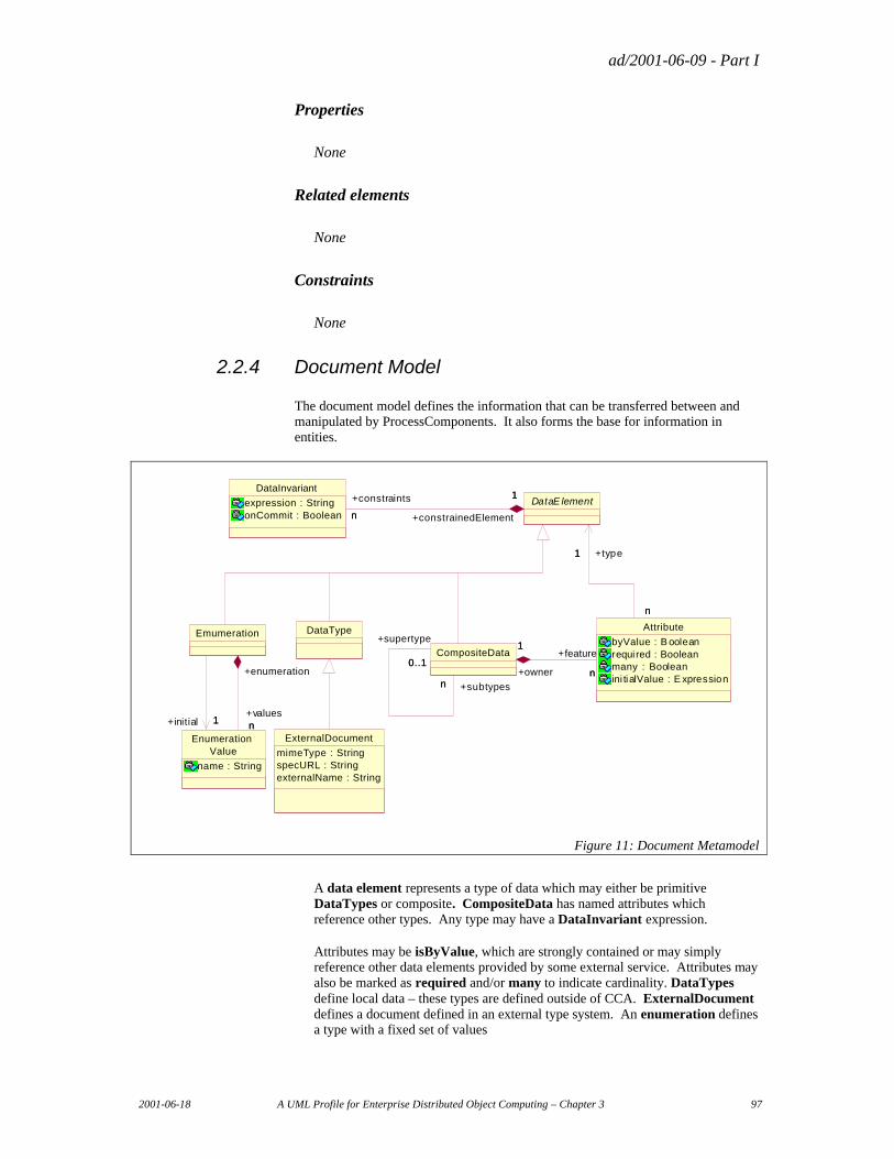
ad/2001-06-09 - Part I
2001-06-18 A UML Profile for Enterprise Distributed Object Computing – Chapter 3 97
Properties
None
Related elements
None
Constraints
None
2.2.4 Document Model
The document model defines the information that can be transferred between and manipulated by ProcessComponents. It also forms the base for information in entities.
DataType
Enumeration Value
name : String
Emumeration
n+valuesn
+enumeration
1+initial 1
DataInvariant
expression : StringonCommit : Boolean
DataE lement1
n +constrainedElement
1+constraints
n
Attribute
byValue : B ooleanrequi red : Booleanmany : Booleanini tialValue : E xpression
1
n
+type1
n
CompositeData
n
1+feature
n+owner
1
n
0..1
+subtypesn
+supertype
0..1
ExternalDocument
mimeType : StringspecURL : StringexternalName : String
Figure 11: Document Metamodel
A data element represents a type of data which may either be primitive DataTypes or composite. CompositeData has named attributes which reference other types. Any type may have a DataInvariant expression.
Attributes may be isByValue, which are strongly contained or may simply reference other data elements provided by some external service. Attributes may also be marked as required and/or many to indicate cardinality. DataTypes define local data – these types are defined outside of CCA. ExternalDocument defines a document defined in an external type system. An enumeration defines a type with a fixed set of values
ad/2001-06-09 - Part I
98 A UML Profile for Enterprise Distributed Object Computing – Chapter 3 2001-06-18
2.2.4.1 DataElement
Semantics
DataElement is the abstract supertype of all data types. It defines some kind of information.
UML base element(s) in the Profile and Stereotype
Classifier (no stereotype)
Fully Scoped name
ECA::DocumentModel::DataElement
Owned by
Package
Extends
PackageContent
Properties
None
Related elements
constraints
Constraints applied to the values of this data type.
Constraints
None
2.2.4.2 DataType
Semantics
A primitive data type, such as an integer, string, picture, movie…
Primitive data types may have their structure and semantics defined outside of CCA. The following data types are defined for all specializations of CCA: String, Integer, Float, Decimal, Boolean.
UML base element(s) in the Profile and Stereotype
DataType (no stereotype)
ad/2001-06-09 - Part I
2001-06-18 A UML Profile for Enterprise Distributed Object Computing – Chapter 3 99
Fully Scoped name
ECA::DocumentModel::DataType
Owned by
Package
Extends
DataElement
Properties
None
Related elements
None
Constraints
None
2.2.4.3 Enumeration
Semantics
An enumeration defines a type that may have a fixed set of values.
UML base element(s) in the Profile and Stereotype
Corresponds to User defined enumeration stereotypes of UML DataType.
Fully Scoped name
ECA::DOCUMENTMODEL::Enumeration
Owned by
Package
Extends
DataElement
ad/2001-06-09 - Part I
100 A UML Profile for Enterprise Distributed Object Computing – Chapter 3 2001-06-18
Properties
None
Related elements
Values
The set of values the enumeration may have.
UML Representation
ModelElement::namespace
Initial
The initial, or default, value of the enumeration.
UML Representation
Tagged value
Constraints
None
2.2.4.4 EnumerationValue
Semantics
A possible value of an enumeration.
UML base element(s) in the Profile and Stereotype
The values of User defined enumeration stereotypes of UML DataType.
Fully Scoped name
ECA::DOCUMENTMODEL::EnumerationValue
Owned by
Enumeration
Extends
None
ad/2001-06-09 - Part I
2001-06-18 A UML Profile for Enterprise Distributed Object Computing – Chapter 3 101
Properties
name
Related elements
Enumeration
The owning enumeration.
UML Representation
ModelElement:namespace
Constraints
None
2.2.4.5 CompositeData
Semantics
A datatype composed of other types in the form of attributes.
UML base element(s) in the Profile and Stereotype
Class Stereotyped as <<CompositeData>>
Fully Scoped name
ECA::DocumentModel::CompositreData
Owned by
Package
ad/2001-06-09 - Part I
102 A UML Profile for Enterprise Distributed Object Computing – Chapter 3 2001-06-18
Extend
DataElements
Properties
None
Related elements
Feature
The attributes which form the composite.
UML Representation
Classifier.feature
Supertype
A type from which this type is specialized. The composite will include all attributes of all supertypes as attributes of itself.
Subtypes
The types derived from this type.Constraints
UML Representation
Generalization
2.2.4.6 Attribute
Semantics
Defines one “slot” of a composite type that may be filled by a data element of “type”.
UML base element(s) in the Profile and Stereotype
Attribute (No stereotype)
Fully Scoped name
ECA::DOCUMENTMODEL::Attribute
Owned by
CompositeData
ad/2001-06-09 - Part I
2001-06-18 A UML Profile for Enterprise Distributed Object Computing – Chapter 3 103
Extends
None
Properties
isByValue
Indicates that the composite data is stored within the composite as opposed to referenced by the composite.
UML Representation
Stand-alone Tagged Value to apply to UML Attribute (a Stereotype of Attrbute is not created to hold this TaggedValue :
required
Indicates that the attribute slot must have a value for the composite to be valid.
UML Representation
StructuralFeature::multiplicity
many
Indicates that there may be multiple occurrences of values. These values are always ordered.
UML Representation
StructuralFeature::multiplicity
initialValue
An expression returning the initial value of the attribute.
UML Representation
Attribute::initialValue
Related elements
type
The type of information which the attribute may hold. Type instances may also be filled by a subtype.
ad/2001-06-09 - Part I
104 A UML Profile for Enterprise Distributed Object Computing – Chapter 3 2001-06-18
UML Representation
StructuralFeature::type
owner
The composite of which this is an attribute.
UML Representation
ModelElement::namespace
Constraints
None
2.2.4.7 DataInvariant
Semantics
A constraint on the legal values of a data element.
UML base element(s) in the Profile and Stereotype
Constraint
Fully Scoped name
ECA::DOCUMENTMODEL::DataInvarient
Owned by
DataElement
Extends
None
Properties
Expression
The expression which must return true for the data element to be valid.
UML Representation
Constraint::body
ad/2001-06-09 - Part I
2001-06-18 A UML Profile for Enterprise Distributed Object Computing – Chapter 3 105
isOnCommit (Default: False)
True indicates that the constraint only applies to a fully formed data element, not to one under construction.
UML Representation
Tagged Value
Related elements
ConstrainedElement
The data element that will be constrained.
UML Representation
Constraint::constrainedElement
2.2.4.8 ExternalDocument
Semantics
A large, self contained document defined in an external type systems such as XML, Cobol or Java that may or may not map to the ECA document model.
UML base element(s) in the Profile and Stereotype
DataType Stereotyped as <<ExternalDocument>>
Fully Scoped name
ECA::DOCUMENTMODEL::ExternalDocument
Owned by
Package
Extends
DataElement
Properties
All properties are tagged values

ad/2001-06-09 - Part I
106 A UML Profile for Enterprise Distributed Object Computing – Chapter 3 2001-06-18
MimeType
The type of the document specified as a string compatible with the “mime” declarations.
SpecURL
A reference to an external document definition compatible with the mimiType, such as a DTD or Schema. If the MimeType does not define a specification form (E.G. GIF) then this attribute will be blank.
ExternalName
The name of the document within the SpecURL. For example, an element name within a DTD. If the MimeType does not define a specification form (E.G. GIF) or the specification form only specifies one document then this attribute will be blank.
Related elements
None
Constraints
None
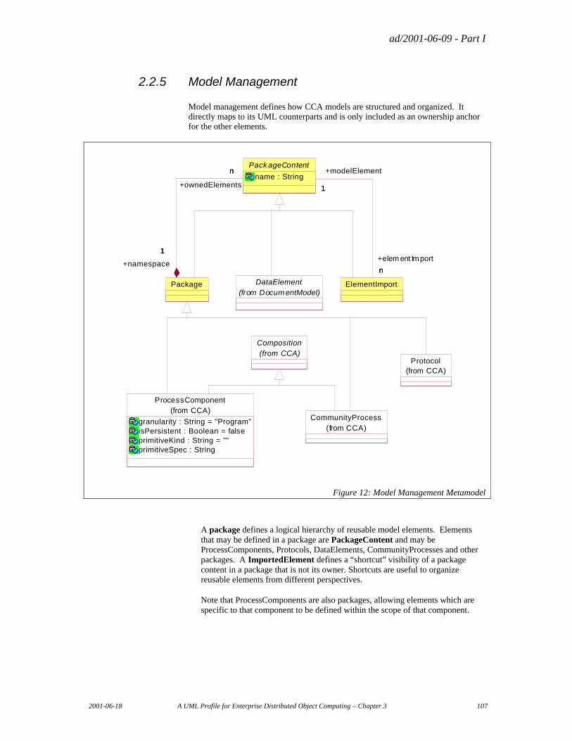
ad/2001-06-09 - Part I
2001-06-18 A UML Profile for Enterprise Distributed Object Computing – Chapter 3 107
2.2.5 Model Management
Model management defines how CCA models are structured and organized. It directly maps to its UML counterparts and is only included as an ownership anchor for the other elements.
ProcessComponent
granularity : String = "Program"isPersistent : Boolean = falseprimitiveKind : String = ""primitiveSpec : String
(from CCA)
DataElement(from DocumentModel)
Package
Pack ageContent
name : Stringn
1
+ownedElements
n
+namespace
1
ElementImport
1
n
+modelElement
1
+elem ent Import
n
CommunityProcess(from CCA)
Composition(from CCA)
Protocol(from CCA)
Figure 12: Model Management Metamodel
A package defines a logical hierarchy of reusable model elements. Elements that may be defined in a package are PackageContent and may be ProcessComponents, Protocols, DataElements, CommunityProcesses and other packages. A ImportedElement defines a “shortcut” visibility of a package content in a package that is not its owner. Shortcuts are useful to organize reusable elements from different perspectives.
Note that ProcessComponents are also packages, allowing elements which are specific to that component to be defined within the scope of that component.
ad/2001-06-09 - Part I
108 A UML Profile for Enterprise Distributed Object Computing – Chapter 3 2001-06-18
2.2.5.1 Package
Semantics
Defines a structural container for “top level” model elements that may be referenced by name for other model elements.
UML base element(s) in the Profile and Stereotype
Package
Fully Scoped name
ECA::ModelManagement::Package
Owned by
Package or model (global scope)
Extends
PackageContent
Properties
None
Related elements
OwnedElements
The model elements within the package and visible from outside of the package.
UML Representation
Namespace::OwnedElement
Constraints
None
2.2.5.2 PackageContent
Semantics
An abstract capability that represents an element that may be placed in a package and thus referenced by name from any other element.
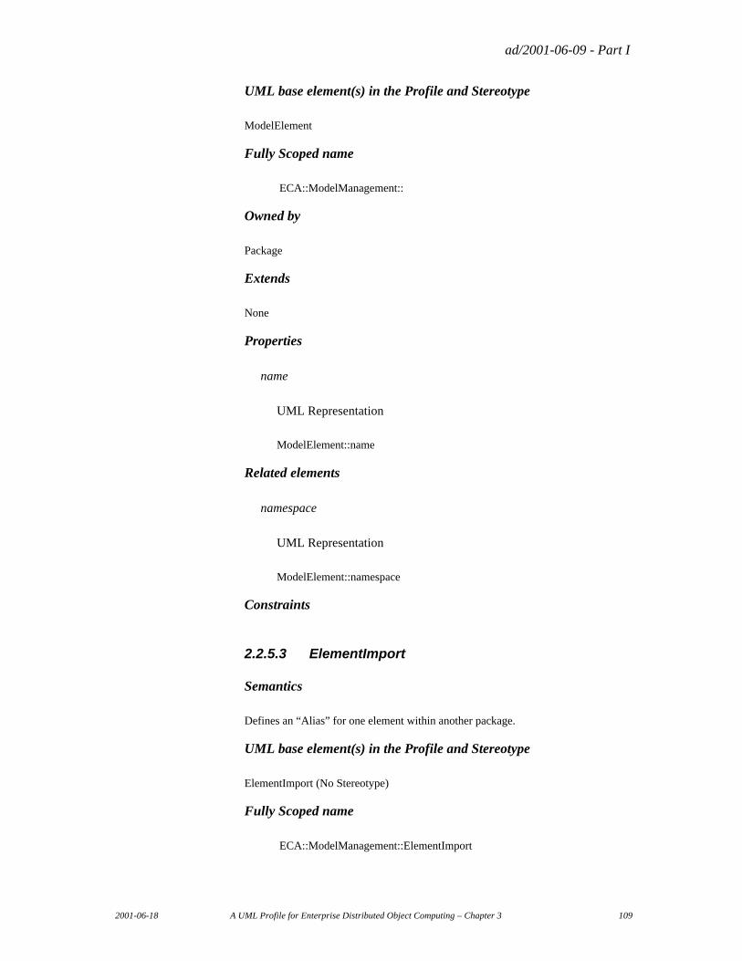
ad/2001-06-09 - Part I
2001-06-18 A UML Profile for Enterprise Distributed Object Computing – Chapter 3 109
UML base element(s) in the Profile and Stereotype
ModelElement
Fully Scoped name
ECA::ModelManagement::
Owned by
Package
Extends
None
Properties
name
UML Representation
ModelElement::name
Related elements
namespace
UML Representation
ModelElement::namespace
Constraints
2.2.5.3 ElementImport
Semantics
Defines an “Alias” for one element within another package.
UML base element(s) in the Profile and Stereotype
ElementImport (No Stereotype)
Fully Scoped name
ECA::ModelManagement::ElementImport
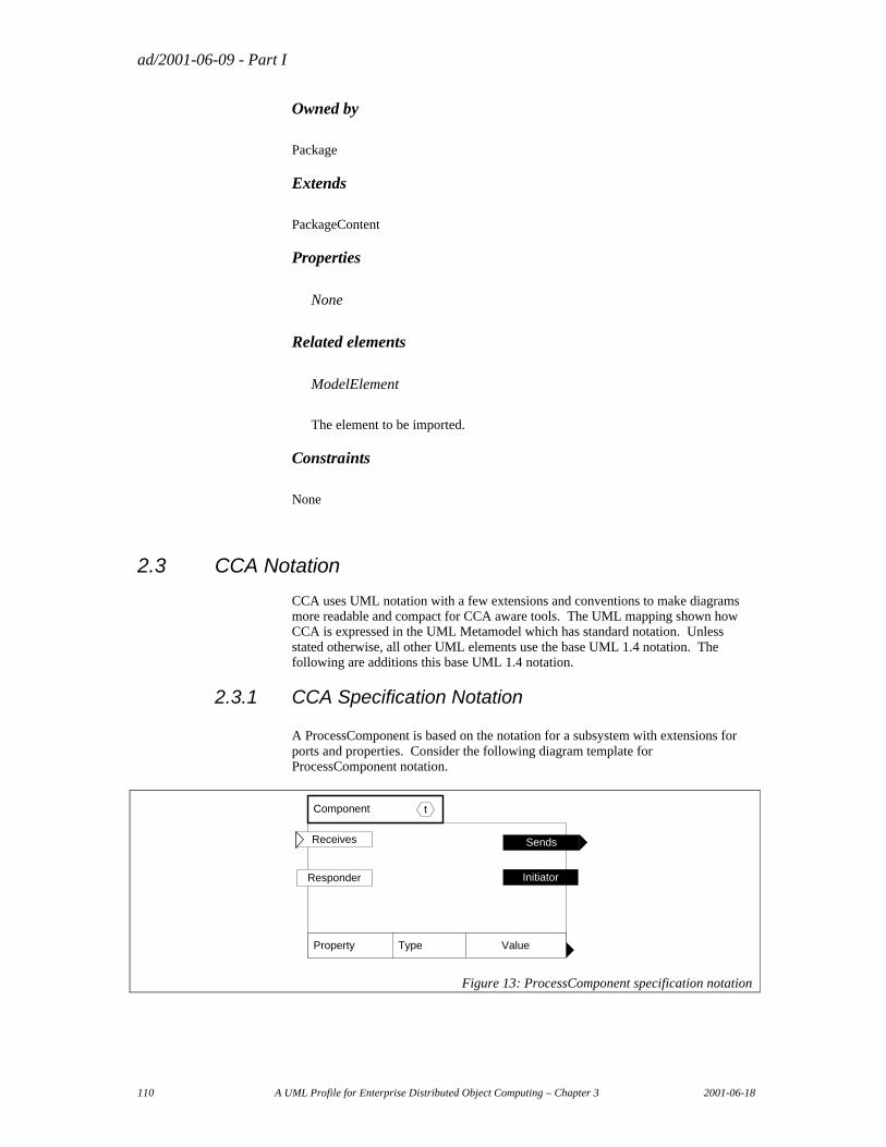
ad/2001-06-09 - Part I
110 A UML Profile for Enterprise Distributed Object Computing – Chapter 3 2001-06-18
Owned by
Package
Extends
PackageContent
Properties
None
Related elements
ModelElement
The element to be imported.
Constraints
None
2.3 CCA Notation
CCA uses UML notation with a few extensions and conventions to make diagrams more readable and compact for CCA aware tools. The UML mapping shown how CCA is expressed in the UML Metamodel which has standard notation. Unless stated otherwise, all other UML elements use the base UML 1.4 notation. The following are additions this base UML 1.4 notation.
2.3.1 CCA Specification Notation
A ProcessComponent is based on the notation for a subsystem with extensions for ports and properties. Consider the following diagram template for ProcessComponent notation.
Component
Property Type
Responder Initiator
Value
t
Receives Sends
Figure 13: ProcessComponent specification notation
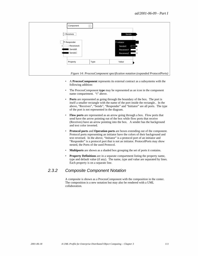
ad/2001-06-09 - Part I
2001-06-18 A UML Profile for Enterprise Distributed Object Computing – Chapter 3 111
Component t
Property Type Value
SendsReceives
Initiator
SendsX
ReceivesY
ReceivesZ
Responder
ReceivesA
SendsB
SendsC
Figure 14: ProcessComponent specification notation (expanded ProtocolPorts)
• A ProcessComponent represents its external contract as a subsystems with the following addition:
• The ProcessComponent type may be represented as an icon in the component name compartment. “t” above.
• Ports are represented as going through the boundary of the box. The port is itself a smaller rectangle with the name of the port inside the rectangle.. In the above, “Receives”, “Sends”, “Responder” and “Initiator” are all ports. The type of the port is not represented in the diagram.
• Flow ports are represented as an arrow going through a box. Flow ports that send have the arrow pointing out of the box while flow ports that receive (Receives) have an arrow pointing into the box. A sender has the background and text color inverted.
• Protocol ports and Operation ports are boxes extending out of the component. Protocol ports representing an initiator have the colors of their background and text reversed. In the above, “Initiator” is a protocol port of an initiator and “Responder” is a protocol port that is not an initiator. ProtocolPorts may show nested, the Ports of the used Protocol.
• Multiports are shown as a shaded box grouping the set of ports it contains.
• Property Definitions are in a separate compartment listing the property name, type and default value (if any). The name, type and value are separated by lines. Each property is on a separate line.
2.3.2 Composite Component Notation
A composite is shown as a ProcessComponent with the composition in the center. The composition is a new notation but may also be rendered with a UML collaboration.
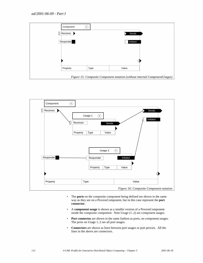
ad/2001-06-09 - Part I
112 A UML Profile for Enterprise Distributed Object Computing – Chapter 3 2001-06-18
Component
Responder Initiator
t
Receives
Property Type Value
Sends
Figure 15: Composite Component notation (without internal ComponentUsages)
Component t
Initiator
Sends
Responder
Receives
Usage 1 t
Property Type Value
SendsReceives
Usage 2 t
Property Type Value
Responder Initiator
Property Type Value
Figure 16: Composite Component notation
• The ports on the composite component being defined are shown in the same way as they are on a ProcessComponent, but in this case represent the port connector.
• A component usage is shown as a smaller version of a ProcessComponent inside the composite component. Note Usage (1..2) are component usages.
• Port connectos are shown in the same fashion as ports, on component usages. The ports on Usage 1..2 are all port usages.
• Connectors are shown as lines between port usages or port proxies. All the lines in the above are connectors.
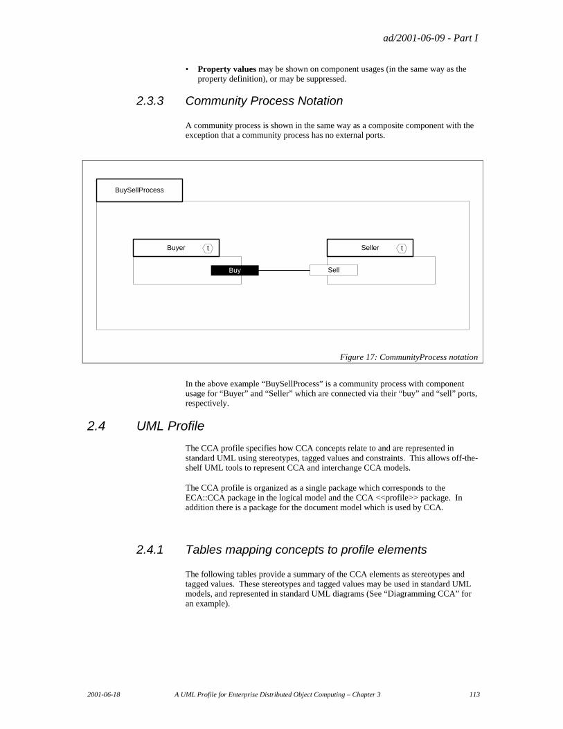
ad/2001-06-09 - Part I
2001-06-18 A UML Profile for Enterprise Distributed Object Computing – Chapter 3 113
• Property values may be shown on component usages (in the same way as the property definition), or may be suppressed.
2.3.3 Community Process Notation
A community process is shown in the same way as a composite component with the exception that a community process has no external ports.
BuySellProcess
Buyer t
Buy
Seller t
Sell
Figure 17: CommunityProcess notation
In the above example “BuySellProcess” is a community process with component usage for “Buyer” and “Seller” which are connected via their “buy” and “sell” ports, respectively.
2.4 UML Profile
The CCA profile specifies how CCA concepts relate to and are represented in standard UML using stereotypes, tagged values and constraints. This allows off-the-shelf UML tools to represent CCA and interchange CCA models.
The CCA profile is organized as a single package which corresponds to the ECA::CCA package in the logical model and the CCA <<profile>> package. In addition there is a package for the document model which is used by CCA.
2.4.1 Tables mapping concepts to profile elements
The following tables provide a summary of the CCA elements as stereotypes and tagged values. These stereotypes and tagged values may be used in standard UML models, and represented in standard UML diagrams (See “Diagramming CCA” for an example).
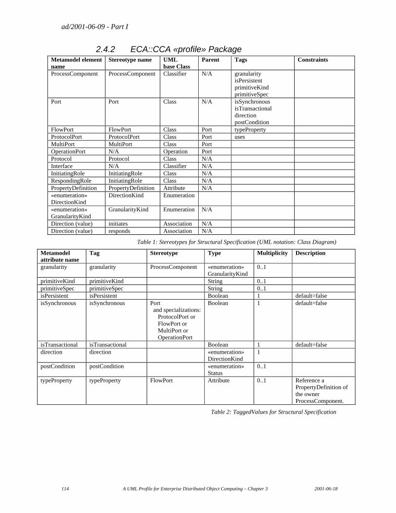
ad/2001-06-09 - Part I
114 A UML Profile for Enterprise Distributed Object Computing – Chapter 3 2001-06-18
2.4.2 ECA::CCA «profile» Package Metamodel element name
Stereotype name UML base Class
Parent Tags Constraints
ProcessComponent ProcessComponent Classifier N/A granularity isPersistent primitiveKind primitiveSpec
Port Port Class N/A isSynchronous isTransactional direction postCondition
FlowPort FlowPort Class Port typeProperty ProtocolPort ProtocolPort Class Port uses MultiPort MultiPort Class Port OperationPort N/A Operation Port Protocol Protocol Class N/A Interface N/A Classifier N/A InitiatingRole InitiatingRole Class N/A RespondingRole InitiatingRole Class N/A PropertyDefinition PropertyDefinition Attribute N/A «enumeration» DirectionKind
DirectionKind Enumeration
«enumeration» GranularityKind
GranularityKind Enumeration N/A
Direction (value) initiates Association N/A Direction (value) responds Association N/A
Table 1: Stereotypes for Structural Specification (UML notation: Class Diagram)
Table 2: TaggedValues for Structural Specification
Metamodel attribute name
Tag Stereotype Type Multiplicity Description
granularity granularity ProcessComponent «enumeration» GranularityKind
0..1
primitiveKind primitiveKind String 0..1 primitiveSpec primitiveSpec String 0..1 isPersistent isPersistent Boolean 1 default=false isSynchronous isSynchronous
Port and specializations: ProtocolPort or FlowPort or MultiPort or OperationPort
Boolean 1 default=false
isTransactional isTransactional Boolean 1 default=false direction direction «enumeration»
DirectionKind 1
postCondition postCondition «enumeration» Status
0..1
typeProperty typeProperty FlowPort Attribute 0..1 Reference a PropertyDefinition of the owner ProcessComponent.
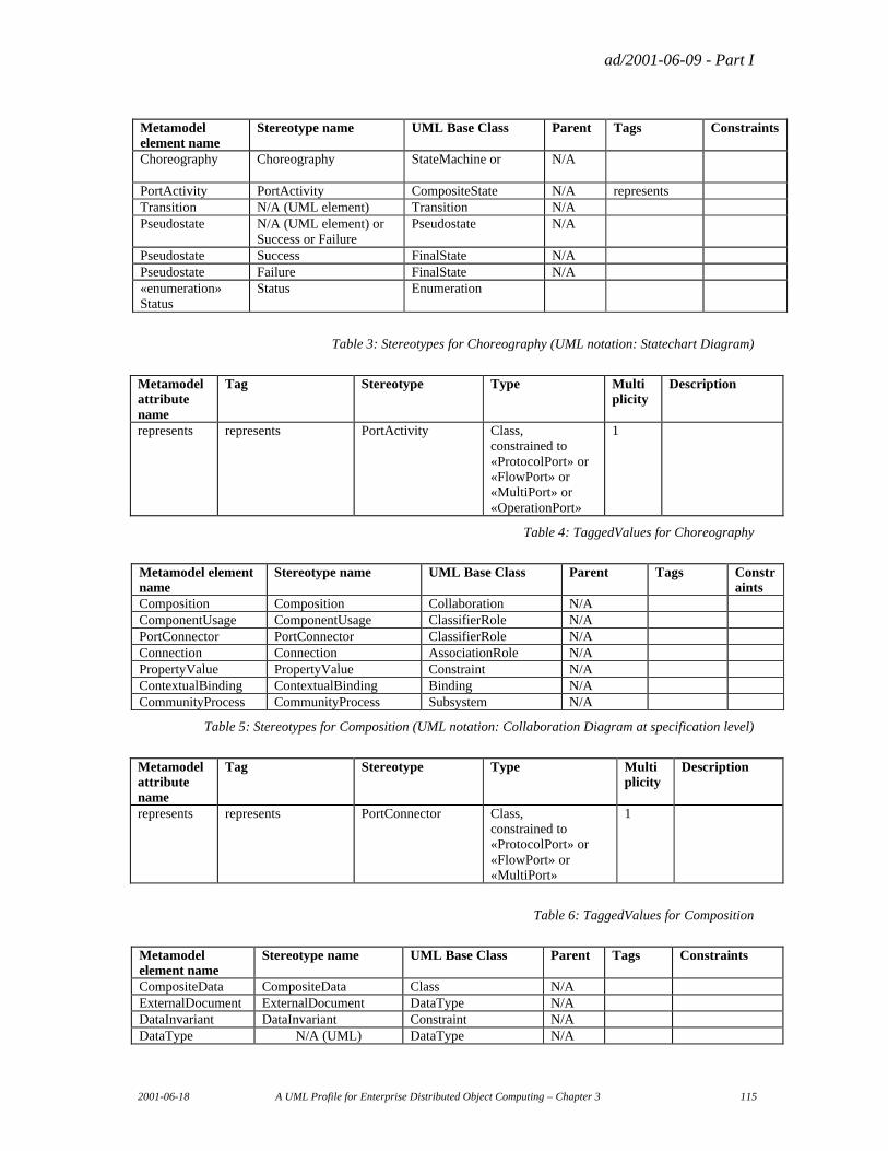
ad/2001-06-09 - Part I
2001-06-18 A UML Profile for Enterprise Distributed Object Computing – Chapter 3 115
Table 3: Stereotypes for Choreography (UML notation: Statechart Diagram)
Metamodel attribute name
Tag Stereotype Type Multi plicity
Description
represents represents PortActivity Class, constrained to «ProtocolPort» or «FlowPort» or «MultiPort» or «OperationPort»
1
Table 4: TaggedValues for Choreography
Metamodel element name
Stereotype name UML Base Class Parent Tags Constraints
Composition Composition Collaboration N/A ComponentUsage ComponentUsage ClassifierRole N/A PortConnector PortConnector ClassifierRole N/A Connection Connection AssociationRole N/A PropertyValue PropertyValue Constraint N/A ContextualBinding ContextualBinding Binding N/A CommunityProcess CommunityProcess Subsystem N/A
Table 5: Stereotypes for Composition (UML notation: Collaboration Diagram at specification level)
Metamodel attribute name
Tag Stereotype Type Multi plicity
Description
represents represents PortConnector Class, constrained to «ProtocolPort» or «FlowPort» or «MultiPort»
1
Table 6: TaggedValues for Composition
Metamodel element name
Stereotype name UML Base Class Parent Tags Constraints
CompositeData CompositeData Class N/A ExternalDocument ExternalDocument DataType N/A DataInvariant DataInvariant Constraint N/A DataType N/A (UML) DataType N/A
Metamodel element name
Stereotype name UML Base Class Parent Tags Constraints
Choreography Choreography StateMachine or
N/A
PortActivity PortActivity CompositeState N/A represents Transition N/A (UML element) Transition N/A Pseudostate N/A (UML element) or
Success or Failure Pseudostate N/A
Pseudostate Success FinalState N/A Pseudostate Failure FinalState N/A «enumeration» Status
Status Enumeration
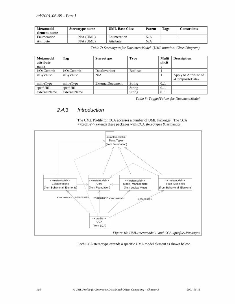
ad/2001-06-09 - Part I
116 A UML Profile for Enterprise Distributed Object Computing – Chapter 3 2001-06-18
Metamodel element name
Stereotype name UML Base Class Parent Tags Constraints
Enumeration N/A (UML) Enumeration N/A Attribute N/A (UML) Attribute N/A
Table 7: Stereotypes for DocumentModel (UML notation: Class Diagram)
Metamodel attribute name
Tag Stereotype Type Multi plicity
Description
isOnCommit isOnCommit DataInvariant Boolean 1 isByValue isByValue N/A 1 Apply to Attribute of
«CompositeData» mimeType mimeType ExternalDocument String 0..1 specURL specURL String 0..1 externalName externalName String 0..1
Table 8: TaggedValues for DocumentModel
2.4.3 Introduction
The UML Profile for CCA accesses a number of UML Packages. The CCA <<profile>> extends these packages with CCA stereotypes & semantics.
Core
(from Foundation)
<<metamodel>>
CCA
(from ECA)
<<profile>>
State_Machines
(from Behavioral_Elements)
<<metamodel>>Collaborations
(from Behavioral_Elements)
<<metamodel>>
Data_Types
(from Foundation)
<<metamodel>>
Model_Management
(from Logical View)
<<metamodel>>
<<access>> <<access>> <<access>><<access>> <<access>>
Figure 18: UML«metamodel» and CCA «profile»Packages
Each CCA stereotype extends a specific UML model element as shown below.
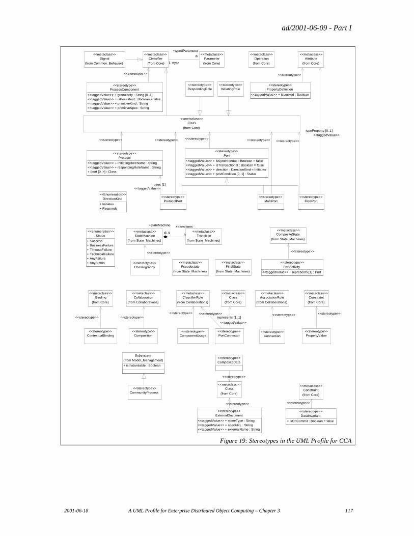
ad/2001-06-09 - Part I
2001-06-18 A UML Profile for Enterprise Distributed Object Computing – Chapter 3 117
Subsystem
(from Model_Management)
+ isInstantiable : Boolean
ProcessComponent
<<taggedValue>> + granularity : String [0..1]<<taggedValue>> + isPersistent : Boolean = false<<taggedValue>> + primitiveKind : String<<taggedValue>> + primitiveSpec : String
<<stereotype>>PropertyDefinition
<<taggedValue>> + isLocked : Boolean
<<stereotype>>
Attribute
(from Core)
<<metaclass>>
DirectionKind
+ Initiates+ Responds
<<Enumeration>>
MultiPort<<stereotype>>
Port
<<taggedValue>> + isSynchronous : Boolean = false<<taggedValue>> + isTransactional : Boolean = false<<taggedValue>> + direction : DirectionKind = Initiates<<taggedValue>> + postCondition [0..1] : Status
<<stereotype>>
FlowPort<<stereotype>>
Class
(from Core)
<<metaclass>>
ProtocolPort<<stereotype>>
Protocol
<<taggedValue>> + initiatingRoleName : String<<taggedValue>> + respondingRoleName : String+ /port [0..n] : Class
<<stereotype>>
Operation
(from Core)
<<metaclass>>
InitiatingRole<<stereotype>>
RespondingRole<<stereotype>>
Signal
(from Common_Behavior)
<<metaclass>>
<<stereotype>>
<<stereotype>>
Classifier
(from Core)
<<metaclass>>
<<stereotype>>
Parameter
(from Core)
<<metaclass>>
1
n
+type1
+typedParameter
n
typeProperty [0..1]<<taggedValue>>
<<stereotype>><<stereotype>><<stereotype>>
uses [1]<<taggedValue>>
<<stereotype>>
PortActivity
<<taggedValue>> + represents [1] : Port
<<stereotype>>
Choreography<<stereotype>>
Pseudostate
(from State_Machines)
<<metaclass>>FinalState
(from State_Machines)
<<metaclass>>
Status
+ Success+ BusinessFailure+ TimeoutFailure+ TechnicalFailure+ AnyFailure+ AnyStatus
<<enumeration>>CompositeState
(from State_Machines)
<<metaclass>>
Transition
(from State_Machines)
<<metaclass>>StateMachine
(from State_Machines)
<<metaclass>>n0..1
+transitions
n
+stateMachine
0..1
<<stereotype>> <<stereotype>>
ClassifierRole
(from Collaborations)
<<metaclass>>
ComponentUsage<<stereotype>>
PortConnector<<stereotype>>
Connection<<stereotype>>
ContextualBinding<<stereotype>>
AssociationRole
(from Collaborations)
<<metaclass>>Binding
(from Core)
<<metaclass>>
PropertyValue<<stereotype>>
Constraint
(from Core)
<<metaclass>>Collaboration
(from Collaborations)
<<metaclass>>
Composition<<stereotype>>
CommunityProcess<<stereotype>>
Class
(from Core)
<<metaclass>>
<<stereotype>> <<stereotype>> <<stereotype>><<stereotype>>
<<stereotype>><<stereotype>> represents [1..1]
<<taggedValue>>
CompositeData<<stereotype>>
Class
(from Core)
<<metaclass>>
DataInvariant
+ isOnCommit : Boolean = false
<<stereotype>>
Constraint
(from Core)
<<metaclass>>
ExternalDocument
<<taggedValue>> + mimeType : String<<taggedValue>> + specURL : String<<taggedValue>> + externalName : String
<<stereotype>>
<<stereotype>>
<<stereotype>><<stereotype>>
Figure 19: Stereotypes in the UML Profile for CCA
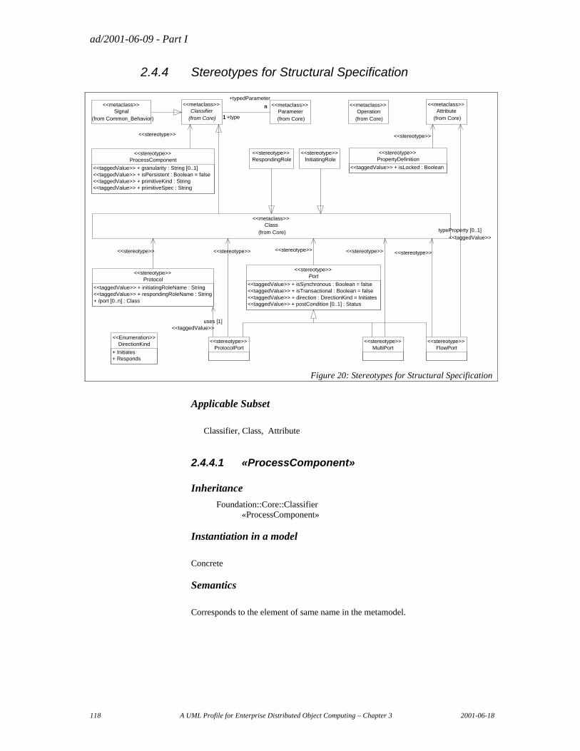
ad/2001-06-09 - Part I
118 A UML Profile for Enterprise Distributed Object Computing – Chapter 3 2001-06-18
2.4.4 Stereotypes for Structural Specification
ProcessComponent<<stereotype>>
<<taggedValue>> + granularity : String [0..1]<<taggedValue>> + isPersistent : Boolean = false<<taggedValue>> + primitiveKind : String<<taggedValue>> + primitiveSpec : String
PropertyDefinition<<stereotype>>
<<taggedValue>> + isLocked : Boolean
Attribute(from Core)
<<metaclass>>
DirectionKind<<Enumeration>>
+ Initiates+ Responds
MultiPort<<stereotype>>
Port<<stereotype>>
<<taggedValue>> + isSynchronous : Boolean = false<<taggedValue>> + isTransactional : Boolean = false<<taggedValue>> + direction : DirectionKind = Initiates<<taggedValue>> + postCondition [0..1] : Status
FlowPort<<stereotype>>
Class(from Core)
<<metaclass>>
<<stereotype>> <<stereotype>>
ProtocolPort<<stereotype>>
<<stereotype>>
Protocol<<stereotype>>
<<taggedValue>> + initiatingRoleName : String<<taggedValue>> + respondingRoleName : String+ /port [0..n] : Class
uses [1]<<taggedValue>>
<<stereotype>>
Operation(from Core)
<<metaclass>>
InitiatingRole<<stereotype>>
RespondingRole<<stereotype>>
<<stereotype>>
typeProperty [0..1]<<taggedValue>>
<<stereotype>>
Signal(from Common_Behavior)
<<metaclass>>Classifier
(from Core)
<<metaclass>>Parameter(from Core)
<<metaclass>>
1
n
+type1
+typedParameter
n
<<stereotype>>
Figure 20: Stereotypes for Structural Specification
Applicable Subset
Classifier, Class, Attribute
2.4.4.1 «ProcessComponent»
Inheritance
Foundation::Core::Classifier «ProcessComponent»
Instantiation in a model
Concrete
Semantics
Corresponds to the element of same name in the metamodel.
ad/2001-06-09 - Part I
2001-06-18 A UML Profile for Enterprise Distributed Object Computing – Chapter 3 119
Relationships3
Relationship Role(s)
Ports owner
Generalization supertype subtypes {only with «ProcessComponent»}
Properties component
Uses owner
ComponentUsages owner
Bindings owner
Bindings bindsTo
Connections _connections
Nodes _nodes
PortUsages extent
Is_A_Choreography is_specialization
Is_A_Composition is_ specialization
PackageElements owner ownerElements
ImportElement modelElement elementImport
Correspondence of metamodel attributes with UML attributes
Metamodel attribute name
UML attribute name
UML attribute owner
Description
name name ModelElement
Tagged Values
Tagged Value name Type Multiplicity Description
granularity String 0..1
primitiveKind String 0..1
primitiveSpec String 0..1
isPersistent Boolean 1 default=false
Constraints expressed generically
The set of all the «Port» of a «ProcessComponent» is the set of «Port» or its specializations, that are aggregated in the «ProcessComponent».
The supertype of a «ProcessComponent» must be a «ProcessComponent».
3 The “Relationships” header references the relationships in which the Model Element participates, and the name of the role in the relationship. The section "Relationships", see 2.4.9 below, includes the specifications for these relationships, and their mapping between metamodel and UML representation.
ad/2001-06-09 - Part I
120 A UML Profile for Enterprise Distributed Object Computing – Chapter 3 2001-06-18
Formal Constraints Expressed in Terms of the UML Metamodel context ProcessComponent inv: supertype->isEmpty() or
supertype.isStereoKinded("ProcessComponent") def: -- the Ports in the ProcessComponent : -- composed in the ProcessComponent let ports : Set( Class) = (association->select( anAssociationEnd :
AssociationEnd | anAssociationEnd.aggregationKind = ak_composite) ->association->connection – association) ->participant ->select( aClassifier : Classifier| anElement.isStereoKinded( «Port»))
Diagram Notation
N/A
2.4.4.2 «Port»
Inheritance
Foundation::Core::Class «Port»
Instantiation in a model
Abstract
Semantics
Corresponds to the element of same name in the metamodel.
The «Port» stereotype has been introduced for clarity and brevity, defining in a common ancestor, the taggedValues corresponding to attributes of Port in the metamodel, and reused along the stereotypes specialization of «Port» : «FlowPort», «ProtocolPort», «MultiPort» and «OperationPort».
Relationships
Relationship Role(s)
Ports ports Represents represents
Correspondence of metamodel attributes with UML attributes
Metamodel attribute name
UML attribute name
UML attribute owner
Description
name name ModelElement
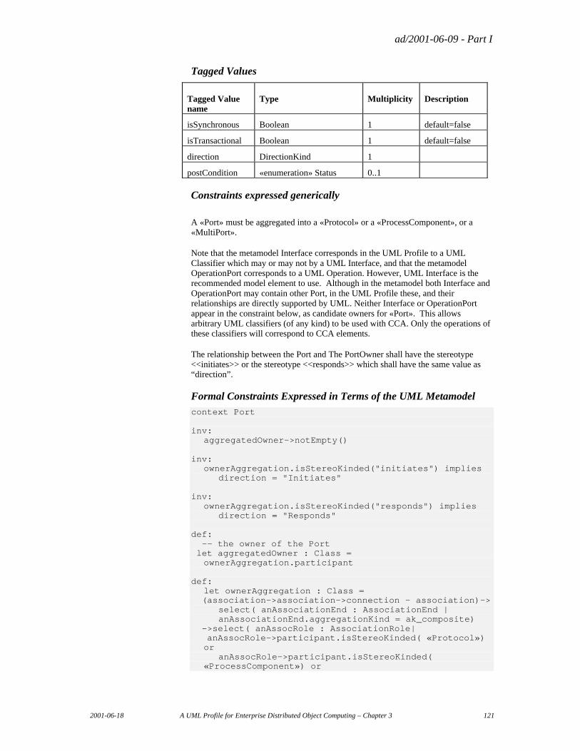
ad/2001-06-09 - Part I
2001-06-18 A UML Profile for Enterprise Distributed Object Computing – Chapter 3 121
Tagged Values
Tagged Value name
Type Multiplicity Description
isSynchronous Boolean 1 default=false
isTransactional Boolean 1 default=false
direction DirectionKind 1
postCondition «enumeration» Status 0..1
Constraints expressed generically
A «Port» must be aggregated into a «Protocol» or a «ProcessComponent», or a «MultiPort».
Note that the metamodel Interface corresponds in the UML Profile to a UML Classifier which may or may not by a UML Interface, and that the metamodel OperationPort corresponds to a UML Operation. However, UML Interface is the recommended model element to use. Although in the metamodel both Interface and OperationPort may contain other Port, in the UML Profile these, and their relationships are directly supported by UML. Neither Interface or OperationPort appear in the constraint below, as candidate owners for «Port». This allows arbitrary UML classifiers (of any kind) to be used with CCA. Only the operations of these classifiers will correspond to CCA elements.
The relationship between the Port and The PortOwner shall have the stereotype <<initiates>> or the stereotype <<responds>> which shall have the same value as “direction”.
Formal Constraints Expressed in Terms of the UML Metamodel context Port inv: aggregatedOwner->notEmpty() inv: ownerAggregation.isStereoKinded("initiates") implies direction = "Initiates" inv: ownerAggregation.isStereoKinded("responds") implies direction = "Responds" def: -- the owner of the Port let aggregatedOwner : Class =
ownerAggregation.participant def: let ownerAggregation : Class = (association->association->connection – association)-> select( anAssociationEnd : AssociationEnd | anAssociationEnd.aggregationKind = ak_composite) ->select( anAssocRole : AssociationRole| anAssocRole->participant.isStereoKinded( «Protocol»)
or anAssocRole->participant.isStereoKinded(
«ProcessComponent») or
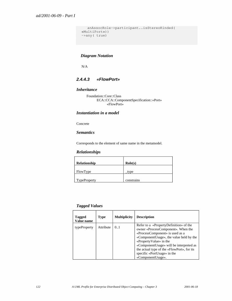
ad/2001-06-09 - Part I
122 A UML Profile for Enterprise Distributed Object Computing – Chapter 3 2001-06-18
anAssocRole->participant..isStereoKinded( «MultiPort»))
->any( true)
Diagram Notation
N/A
2.4.4.3 «FlowPort»
Inheritance
Foundation::Core::Class ECA::CCA::ComponentSpecification::«Port» «FlowPort»
Instantiation in a model
Concrete
Semantics
Corresponds to the element of same name in the metamodel.
Relationships
Relationship Role(s)
FlowType _type
TypeProperty constrains
Tagged Values
Tagged Value name
Type Multiplicity Description
typeProperty Attribute 0..1 Refer to a «PropertyDefinition» of the owner «ProcessComponent». When the «ProcessComponent» is used as a «ComponentUsage», the value held by the «PropertyValue» in the «ComponentUsage» will be interpreted as the actual type of the «FlowPort», for its specific «PortUsage» in the «ComponentUsage».
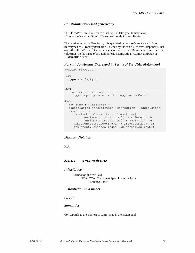
ad/2001-06-09 - Part I
2001-06-18 A UML Profile for Enterprise Distributed Object Computing – Chapter 3 123
Constraints expressed generically
The «FlowPort» must reference as its type a DataType, Enumeration, «CompositeData» or «ExternalDocument» or their specializations.
The typeProperty of «FlowPort», if is specified, it must reference an Attribute stereotyped as «PropertyDefinition», owned by the same «ProcessComponent» that owns the «FlowPort». If the initialValue of the «ProperyDefinition» is set, then the value must be the name of a DataElement, Enumeration, «CompositeData» or «ExternalDocument».
Formal Constraints Expressed in Terms of the UML Metamodel context FlowPort inv: type->notEmpty() inv: typeProperty->isEmpty() or ( typeProperty.owner = this.aggregatedOwner) def: let type : Classifier = (association->association->connection - association)-
>participant ->select( aClassifier : Classifier| anElement.isOclKindOf( DataElement) or anElement.isOclKindOf( Enumeration) or anElement.isStereoKinded( «CompositeData») or anElement.isStereoKinded( «ExternalDocument»))
Diagram Notation
N/A
2.4.4.4 «ProtocolPort»
Inheritance
Foundation::Core::Class ECA::CCA::ComponentSpecification::«Port» «ProtocolPort»
Instantiation in a model
Concrete
Semantics
Corresponds to the element of same name in the metamodel.
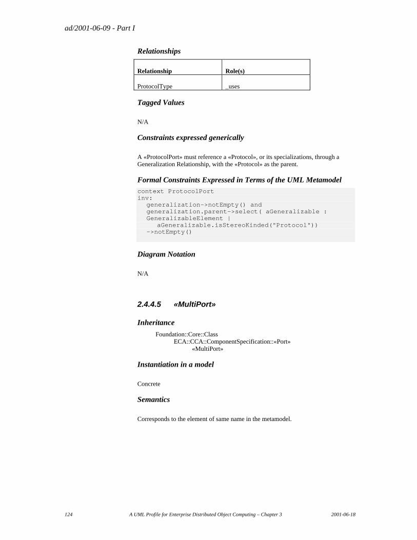
ad/2001-06-09 - Part I
124 A UML Profile for Enterprise Distributed Object Computing – Chapter 3 2001-06-18
Relationships
Relationship Role(s)
ProtocolType _uses
Tagged Values
N/A
Constraints expressed generically
A «ProtocolPort» must reference a «Protocol», or its specializations, through a Generalization Relationship, with the «Protocol» as the parent.
Formal Constraints Expressed in Terms of the UML Metamodel context ProtocolPort inv: generalization->notEmpty() and generalization.parent->select( aGeneralizable :
GeneralizableElement | aGeneralizable.isStereoKinded("Protocol")) ->notEmpty()
Diagram Notation
N/A
2.4.4.5 «MultiPort»
Inheritance
Foundation::Core::Class ECA::CCA::ComponentSpecification::«Port» «MultiPort»
Instantiation in a model
Concrete
Semantics
Corresponds to the element of same name in the metamodel.
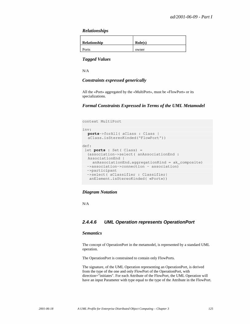
ad/2001-06-09 - Part I
2001-06-18 A UML Profile for Enterprise Distributed Object Computing – Chapter 3 125
Relationships
Relationship Role(s)
Ports owner
Tagged Values
N/A
Constraints expressed generically
All the «Port» aggregated by the «MultiPort», must be «FlowPort» or its specializations.
Formal Constraints Expressed in Terms of the UML Metamodel
context MultiPort inv: ports->forAll( aClass : Class |
aClass.isStereoKinded("FlowPort")) def: let ports : Set( Class) = (association->select( anAssociationEnd :
AssociationEnd | anAssociationEnd.aggregationKind = ak_composite) ->association->connection – association) ->participant ->select( aClassifier : Classifier| anElement.isStereoKinded( «Port»))
Diagram Notation
N/A
2.4.4.6 UML Operation represents OperationPort
Semantics
The concept of OperationPort in the metamodel, is represented by a standard UML operation.
The OperationPort is constrained to contain only FlowPorts.
The signature, of the UML Operation representing an OperationPort, is derived from the type of the one and only FlowPort of the OperationPort, with direction="initiates". For each Attribute of the FlowPort, the UML Operation will have an input Parameter with type equal to the type of the Attribute in the FlowPort.
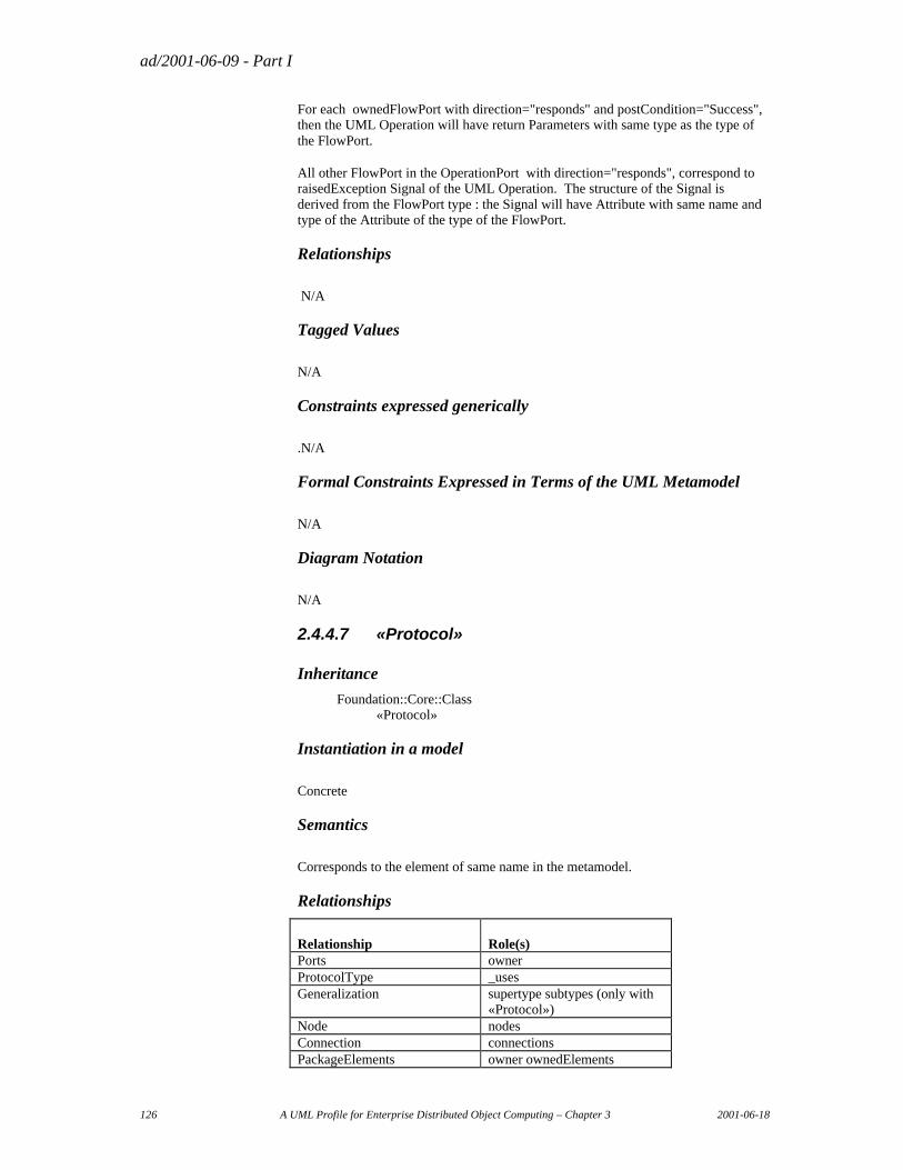
ad/2001-06-09 - Part I
126 A UML Profile for Enterprise Distributed Object Computing – Chapter 3 2001-06-18
For each ownedFlowPort with direction="responds" and postCondition="Success", then the UML Operation will have return Parameters with same type as the type of the FlowPort.
All other FlowPort in the OperationPort with direction="responds", correspond to raisedException Signal of the UML Operation. The structure of the Signal is derived from the FlowPort type : the Signal will have Attribute with same name and type of the Attribute of the type of the FlowPort.
Relationships
N/A
Tagged Values
N/A
Constraints expressed generically
.N/A
Formal Constraints Expressed in Terms of the UML Metamodel
N/A
Diagram Notation
N/A
2.4.4.7 «Protocol»
Inheritance
Foundation::Core::Class «Protocol»
Instantiation in a model
Concrete
Semantics
Corresponds to the element of same name in the metamodel.
Relationships
Relationship Role(s) Ports owner ProtocolType _uses Generalization supertype subtypes (only with
«Protocol») Node nodes Connection connections PackageElements owner ownedElements
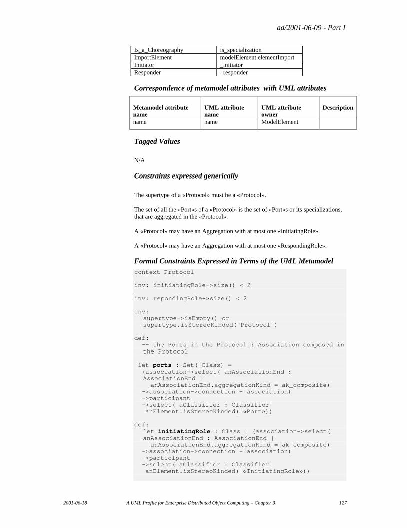
ad/2001-06-09 - Part I
2001-06-18 A UML Profile for Enterprise Distributed Object Computing – Chapter 3 127
Is_a_Choreography is_specialization ImportElement modelElement elementImport Initiator _initiator Responder _responder
Correspondence of metamodel attributes with UML attributes
Metamodel attribute name
UML attribute name
UML attribute owner
Description
name name ModelElement
Tagged Values
N/A
Constraints expressed generically
The supertype of a «Protocol» must be a «Protocol».
The set of all the «Port»s of a «Protocol» is the set of «Port»s or its specializations, that are aggregated in the «Protocol».
A «Protocol» may have an Aggregation with at most one «InitiatingRole».
A «Protocol» may have an Aggregation with at most one «RespondingRole».
Formal Constraints Expressed in Terms of the UML Metamodel context Protocol inv: initiatingRole->size() < 2 inv: repondingRole->size() < 2 inv: supertype->isEmpty() or
supertype.isStereoKinded("Protocol") def: -- the Ports in the Protocol : Association composed in
the Protocol let ports : Set( Class) = (association->select( anAssociationEnd :
AssociationEnd | anAssociationEnd.aggregationKind = ak_composite) ->association->connection – association) ->participant ->select( aClassifier : Classifier| anElement.isStereoKinded( «Port»)) def: let initiatingRole : Class = (association->select(
anAssociationEnd : AssociationEnd | anAssociationEnd.aggregationKind = ak_composite) ->association->connection – association) ->participant ->select( aClassifier : Classifier| anElement.isStereoKinded( «InitiatingRole»))
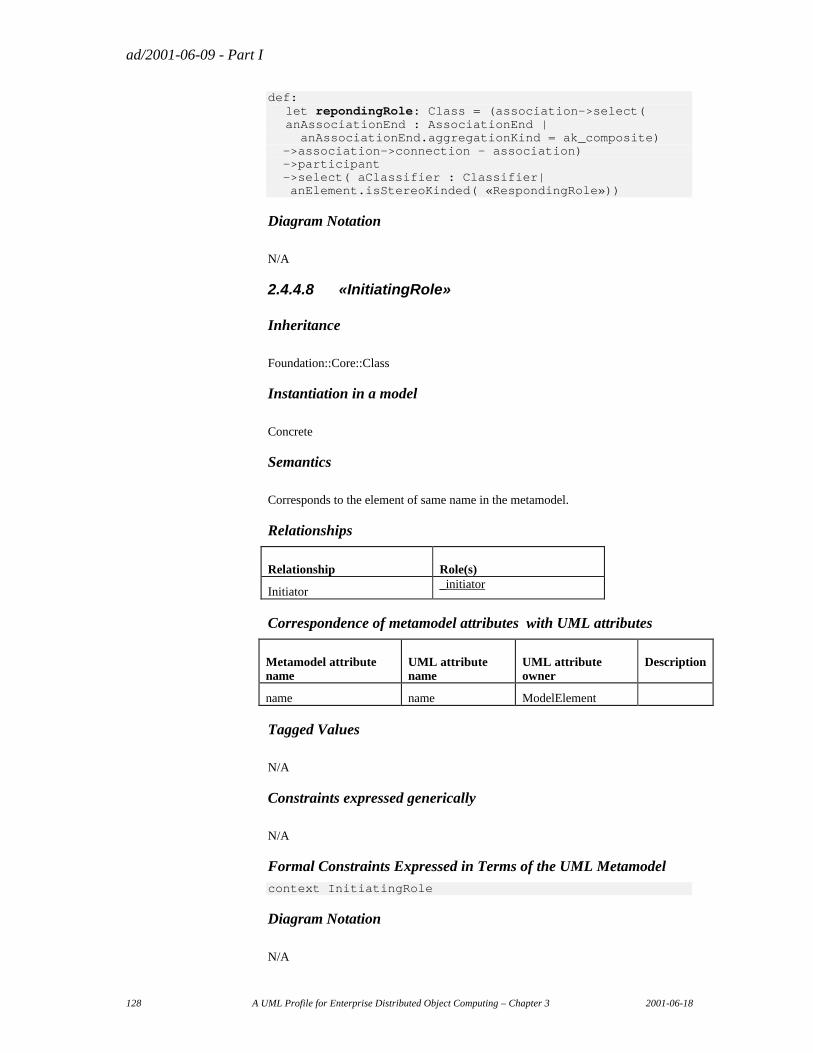
ad/2001-06-09 - Part I
128 A UML Profile for Enterprise Distributed Object Computing – Chapter 3 2001-06-18
def: let repondingRole: Class = (association->select(
anAssociationEnd : AssociationEnd | anAssociationEnd.aggregationKind = ak_composite) ->association->connection – association) ->participant ->select( aClassifier : Classifier| anElement.isStereoKinded( «RespondingRole»))
Diagram Notation
N/A
2.4.4.8 «InitiatingRole»
Inheritance
Foundation::Core::Class
Instantiation in a model
Concrete
Semantics
Corresponds to the element of same name in the metamodel.
Relationships
Relationship Role(s)
Initiator _initiator
Correspondence of metamodel attributes with UML attributes
Metamodel attribute name
UML attribute name
UML attribute owner
Description
name name ModelElement
Tagged Values
N/A
Constraints expressed generically
N/A
Formal Constraints Expressed in Terms of the UML Metamodel context InitiatingRole
Diagram Notation
N/A
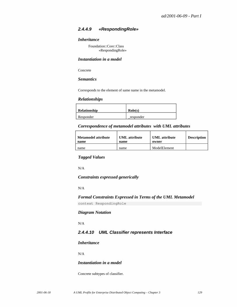
ad/2001-06-09 - Part I
2001-06-18 A UML Profile for Enterprise Distributed Object Computing – Chapter 3 129
2.4.4.9 «RespondingRole»
Inheritance
Foundation::Core::Class «RespondingRole»
Instantiation in a model
Concrete
Semantics
Corresponds to the element of same name in the metamodel.
Relationships
Relationship Role(s)
Responder _responder
Correspondence of metamodel attributes with UML attributes
Metamodel attribute name
UML attribute name
UML attribute owner
Description
name name ModelElement
Tagged Values
N/A
Constraints expressed generically
N/A
Formal Constraints Expressed in Terms of the UML Metamodel context RespondingRole
Diagram Notation
N/A
2.4.4.10 UML Classifier represents Interface
Inheritance
N/A
Instantiation in a model
Concrete subtypes of classifier.
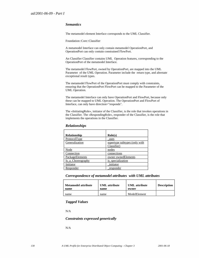
ad/2001-06-09 - Part I
130 A UML Profile for Enterprise Distributed Object Computing – Chapter 3 2001-06-18
Semantics
The metamodel element Interface corresponds to the UML Classifier.
Foundation::Core::Classifier
A metamodel Interface can only contain metamodel OperationPort, and OperationPort can only contain constrained FlowPort.
An Classifier Classifier contains UML Operation features, corresponding to the OperationPort of the metamodel Interface.
The metamodel FlowPort, owned by OperationPort, are mapped into the UML Parameter of the UML Operation. Parameter include the return type, and alternate exceptional result types.
The metamodel FlowPort of the OperationPort must comply with constraints, ensuring that the OperationPort FlowPort can be mapped to the Parameter of the UML Operation.
The metamodel Interface can only have OperationPort and FlowPort, because only these can be mapped to UML Operation. The OperationPort and FlowPort of Interface, can only have direction="responds".
The «InitiatingRole», initiator of the Classifier, is the role that invokes operations in the Classifier. The «RespondingRole», responder of the Classifier, is the role that implements the operations in the Classifier.
Relationships
Relationship Role(s) ProtocolType _uses Generalization supertype subtypes (only with
Classifier) Node nodes Connection connections PackageElements owner ownedElements Is_a_Choreography is_specialization Initiator _initiator Responder _responder
Correspondence of metamodel attributes with UML attributes
Metamodel attribute name
UML attribute name
UML attribute owner
Description
name name ModelElement
Tagged Values
N/A
Constraints expressed generically
N/A
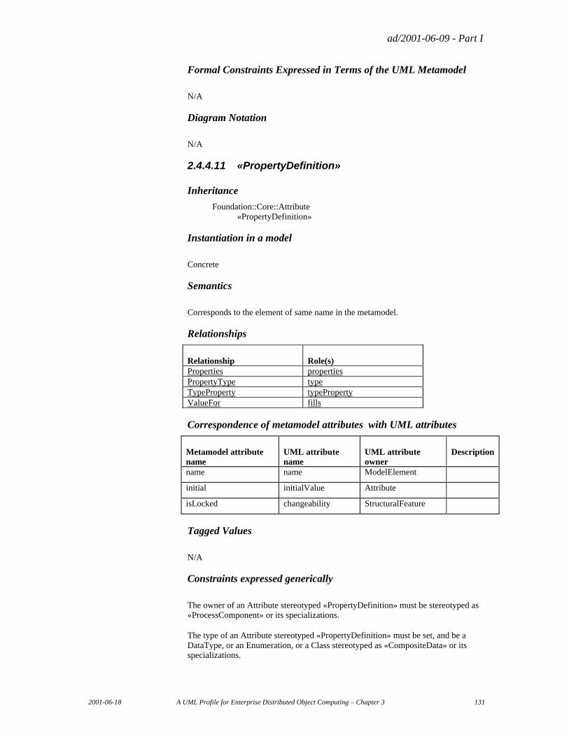
ad/2001-06-09 - Part I
2001-06-18 A UML Profile for Enterprise Distributed Object Computing – Chapter 3 131
Formal Constraints Expressed in Terms of the UML Metamodel
N/A
Diagram Notation
N/A
2.4.4.11 «PropertyDefinition»
Inheritance
Foundation::Core::Attribute «PropertyDefinition»
Instantiation in a model
Concrete
Semantics
Corresponds to the element of same name in the metamodel.
Relationships
Relationship Role(s) Properties properties PropertyType type TypeProperty typeProperty ValueFor fills
Correspondence of metamodel attributes with UML attributes
Metamodel attribute name
UML attribute name
UML attribute owner
Description
name name ModelElement
initial initialValue Attribute
isLocked changeability StructuralFeature
Tagged Values
N/A
Constraints expressed generically
The owner of an Attribute stereotyped «PropertyDefinition» must be stereotyped as «ProcessComponent» or its specializations.
The type of an Attribute stereotyped «PropertyDefinition» must be set, and be a DataType, or an Enumeration, or a Class stereotyped as «CompositeData» or its specializations.
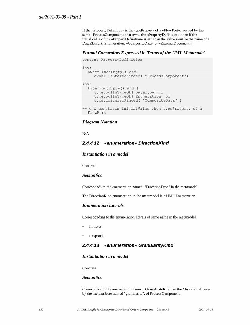
ad/2001-06-09 - Part I
132 A UML Profile for Enterprise Distributed Object Computing – Chapter 3 2001-06-18
If the «PropertyDefinition» is the typeProperty of a «FlowPort», owned by the same «ProcessComponent» that owns the «PropertyDefinition», then if the initialValue of the «ProperyDefinition» is set, then the value must be the name of a DataElement, Enumeration, «CompositeData» or «ExternalDocument».
Formal Constraints Expressed in Terms of the UML Metamodel context PropertyDefinition inv: owner->notEmpty() and owner.isStereoKinded( "ProcessComponent") inv: type->notEmpty() and ( type.oclIsTypeOf( DataType) or type.oclIsTypeOf( Enumeration) or type.isStereoKinded( "CompositeData")) -- ojo constrain initialValue when typeProperty of a
FlowPort
Diagram Notation
N/A
2.4.4.12 «enumeration» DirectionKind
Instantiation in a model
Concrete
Semantics
Corresponds to the enumeration named "DirectionType" in the metamodel.
The DirectionKind enumeration in the metamodel is a UML Enumeration.
Enumeration Literals
Corresponding to the enumeration literals of same name in the metamodel.
• Initiates
• Responds
2.4.4.13 «enumeration» GranularityKind
Instantiation in a model
Concrete
Semantics
Corresponds to the enumeration named “GranularityKind” in the Meta-model, used by the metaatribute named "granularity", of ProcessComponent.
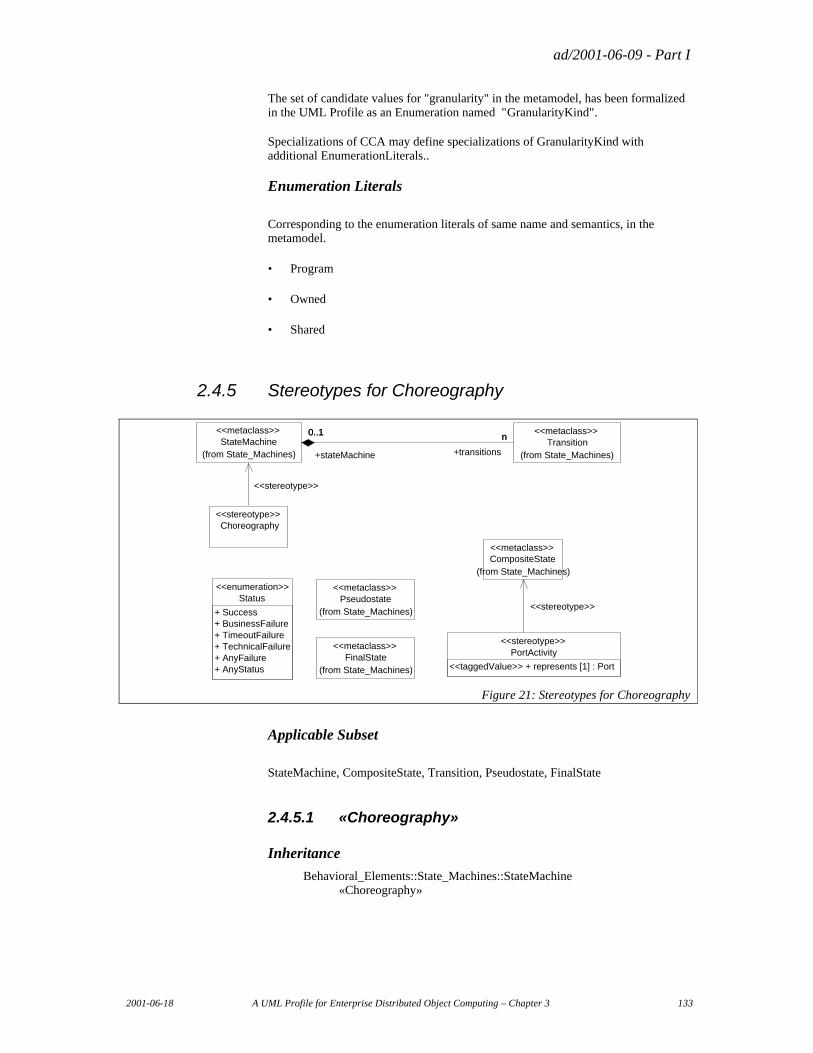
ad/2001-06-09 - Part I
2001-06-18 A UML Profile for Enterprise Distributed Object Computing – Chapter 3 133
The set of candidate values for "granularity" in the metamodel, has been formalized in the UML Profile as an Enumeration named "GranularityKind".
Specializations of CCA may define specializations of GranularityKind with additional EnumerationLiterals..
Enumeration Literals
Corresponding to the enumeration literals of same name and semantics, in the metamodel.
• Program
• Owned
• Shared
2.4.5 Stereotypes for Choreography
PortActivity<<stereotype>>
<<taggedValue>> + represents [1] : Port
Choreography<<stereotype>>
Pseudostate(from State_Machines)
<<metaclass>>
FinalState(from State_Machines)
<<metaclass>>
Transition(from State_Machines)
<<metaclass>>StateMachine
(from State_Machines)
<<metaclass>>n0..1
+transitions
n
+stateMachine
0..1
<<stereotype>>
Status<<enumeration>>
+ Success+ BusinessFailure+ TimeoutFailure+ TechnicalFailure+ AnyFailure+ AnyStatus
CompositeState(from State_Machines)
<<metaclass>>
<<stereotype>>
Figure 21: Stereotypes for Choreography
Applicable Subset
StateMachine, CompositeState, Transition, Pseudostate, FinalState
2.4.5.1 «Choreography»
Inheritance
Behavioral_Elements::State_Machines::StateMachine «Choreography»
ad/2001-06-09 - Part I
134 A UML Profile for Enterprise Distributed Object Computing – Chapter 3 2001-06-18
Instantiation in a model
Concrete
Semantics
Corresponds to the element of same name in the metamodel.
Relationships
Relationship Role(s) Is_a_Choreography is_generalization Nodes _node Connections _connections
Tagged Values
N/A
Constraints expressed generically
The context of a StateMachine stereotyped as «Choreography» will be a Classifier stereotyped as «ProcessComponent» or a Class stereotyped as «Protocol» or a Subsystem stereotyped as <<CommunityProcess>>, or their specializations.
Formal Constraints Expressed in Terms of the UML Metamodel context Choreography inv: context->notEmpty() and ( context->isStereoKinded( «ProcessComponent») or context->isStereoKinded( «Protocol») or context->isStereoKinded( «CommunityProcess»))
Diagram Notation
N/A
2.4.5.2 «PortActivity»
Inheritance
Behavioral_Elements::State_Machines::CompositeState «PortActivity»
Instantiation in a model
Concrete
Semantics
Corresponds to the element of same name in the metamodel.
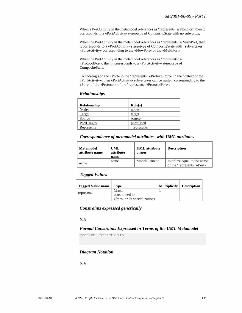
ad/2001-06-09 - Part I
2001-06-18 A UML Profile for Enterprise Distributed Object Computing – Chapter 3 135
When a PortActivity in the metamodel references as "represents" a FlowPort, then it corresponds to a «PortActivity» stereotype of CompositeState with no subvertex.
When the PortActivity in the metamodel references as "represents" a MultiPort, then it corresponds to a «PortActivity» stereotype of CompositeState with subvertexes «PortActivity» corresponding to the «FlowPort» of the «MultiPort».
When the PortActivity in the metamodel references as "represents" a «ProtocolPort», then it corresponds to a «PortActivity» stereotype of CompositeState.
To choreograph the «Port» in the "represents" «ProtocolPort», in the context of the «PortActivity», then «PortActivity» subvertexes can be nested, corresponding to the «Port» of the «Protocol» of the "represents" «ProtocolPort».
Relationships
Relationship Role(s) Nodes nodes Target target Source source PortUsages portsUsed Represents _represents
Correspondence of metamodel attributes with UML attributes
Metamodel attribute name
UML attribute name
UML attribute owner
Description
name name ModelElement Initialize equal to the name
of the "represents" «Port»
Tagged Values
Tagged Value name Type Multiplicity Description
represents Class, constrained to «Port» or its specializations
1
Constraints expressed generically
N/A
Formal Constraints Expressed in Terms of the UML Metamodel context PortActivity
Diagram Notation
N/A
ad/2001-06-09 - Part I
136 A UML Profile for Enterprise Distributed Object Computing – Chapter 3 2001-06-18
2.4.5.3 UML Transition
Inheritance
N/A
Instantiation in a model
Concrete
Semantics
The metamodel element Transition corresponds to the UML model element of the same name.
Behavioral_Elements::State_Machines::Transition
The "preCondition" metaattribute corresponds to a UML Guard whose expression body will evaluate true under the same conditions as it would the "preCondition" metaattribute.
Relationships
Relationship Role(s) Target incoming Source outgoing Connections connections
Tagged Values
N/A
Constraints expressed generically
N/A
Formal Constraints Expressed in Terms of the UML Metamodel
N/A
Diagram Notation
N/A
2.4.5.4 UML Pseudostate
Inheritance
N/A
ad/2001-06-09 - Part I
2001-06-18 A UML Profile for Enterprise Distributed Object Computing – Chapter 3 137
Instantiation in a model
Concrete
Semantics
The metamodel element Pseudostate corresponds to the UML model element of the same name.
Behavioral_Elements::State_Machines:: Pseudostate
CCA Pseudostate mapps to UML Pseudostate except when the CCA-metamodel attribute "kind" of the Pseudostate has value "Success" or "Failure", that map to stereotypes of UML FinalState. Please see stereotypes «Success» and «Failure», below.
The semantics of the metamodel element Pseudostate are equivalent to the semantics of UML Pseudostate with corresponding "kind" values.
Metamodel kind UML kind : Foundation::Data_Types::PseudostateKind
choice pk_choice
fork pk_fork
initial pk_initial
join pk_join
Relationships
Relationship Role(s) Nodes nodes Target target Source source PortUsages portsUsed
Tagged Values
N/A
Constraints expressed generically
N/A
Formal Constraints Expressed in Terms of the UML Metamodel
N/A
Diagram Notation
N/A
ad/2001-06-09 - Part I
138 A UML Profile for Enterprise Distributed Object Computing – Chapter 3 2001-06-18
2.4.5.5 «Success»
Inheritance
Behavioral_Elements::State_Machines::FinalState «Success»
Instantiation in a model
Concrete
Semantics
Corresponds to the element of same name in the metamodel.
Relationships
Relationship Role(s) Nodes nodes Target target Source source PortUsages portsUsed
Tagged Values
N/A
Constraints expressed generically
N/A
Formal Constraints Expressed in Terms of the UML Metamodel
N/A
Diagram Notation
N/A
2.4.5.6 «Failure»
Inheritance
Behavioral_Elements::State_Machines::FinalState «Failure»
Instantiation in a model
Concrete
ad/2001-06-09 - Part I
2001-06-18 A UML Profile for Enterprise Distributed Object Computing – Chapter 3 139
Semantics
Corresponds to the element of same name in the metamodel.
Relationships
Relationship Role(s) Nodes nodes Target target Source source PortUsages portsUsed
Tagged Values
N/A
Constraints expressed generically
N/A
Formal Constraints Expressed in Terms of the UML Metamodel
N/A
Diagram Notation
N/A
2.4.5.7 «enumeration» Status
Instantiation in a model
Concrete
Semantics
Corresponds to the enumeration of same name in the metamodel.
Enumeration Literals
Corresponding to the enumeration literals of the enumeration of same name in the metamodel,
• Success
• BusinessFailure
• TimeoutFailure
• TechnicalFailure
• AnyFailure
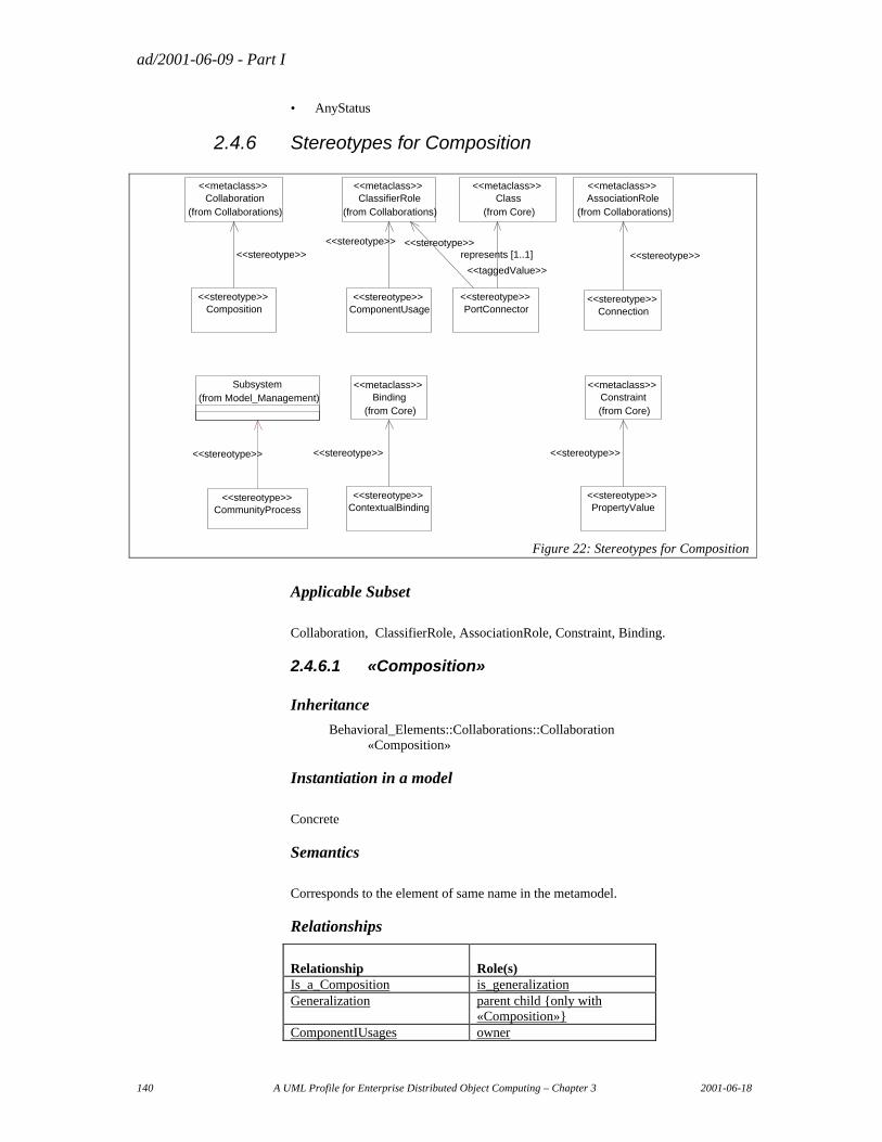
ad/2001-06-09 - Part I
140 A UML Profile for Enterprise Distributed Object Computing – Chapter 3 2001-06-18
• AnyStatus
2.4.6 Stereotypes for Composition
ClassifierRole(from Collaborations)
<<metaclass>>
ComponentUsage<<stereotype>>
<<stereotype>>
PortConnector<<stereotype>>
<<stereotype>>
Connection<<stereotype>>
ContextualBinding<<stereotype>>
AssociationRole(from Collaborations)
<<metaclass>>
<<stereotype>>
Binding(from Core)
<<metaclass>>
<<stereotype>>
PropertyValue<<stereotype>>
Constraint(from Core)
<<metaclass>>
<<stereotype>>
Collaboration(from Collaborations)
<<metaclass>>
Composition<<stereotype>>
<<stereotype>>
CommunityProcess<<stereotype>>
Class(from Core)
<<metaclass>>
represents [1..1]
<<taggedValue>>
Subsystem(from Model_Management)
<<stereotype>>
Figure 22: Stereotypes for Composition
Applicable Subset
Collaboration, ClassifierRole, AssociationRole, Constraint, Binding.
2.4.6.1 «Composition»
Inheritance
Behavioral_Elements::Collaborations::Collaboration «Composition»
Instantiation in a model
Concrete
Semantics
Corresponds to the element of same name in the metamodel.
Relationships
Relationship Role(s) Is_a_Composition is_generalization Generalization parent child {only with
«Composition»} ComponentIUsages owner
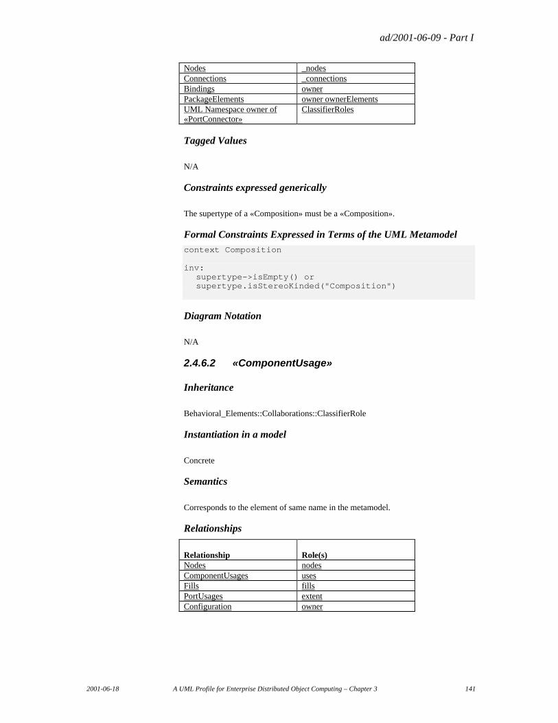
ad/2001-06-09 - Part I
2001-06-18 A UML Profile for Enterprise Distributed Object Computing – Chapter 3 141
Nodes _nodes Connections _connections Bindings owner PackageElements owner ownerElements UML Namespace owner of «PortConnector»
ClassifierRoles
Tagged Values
N/A
Constraints expressed generically
The supertype of a «Composition» must be a «Composition».
Formal Constraints Expressed in Terms of the UML Metamodel context Composition inv: supertype->isEmpty() or
supertype.isStereoKinded("Composition")
Diagram Notation
N/A
2.4.6.2 «ComponentUsage»
Inheritance
Behavioral_Elements::Collaborations::ClassifierRole
Instantiation in a model
Concrete
Semantics
Corresponds to the element of same name in the metamodel.
Relationships
Relationship Role(s) Nodes nodes ComponentUsages uses Fills fills PortUsages extent Configuration owner
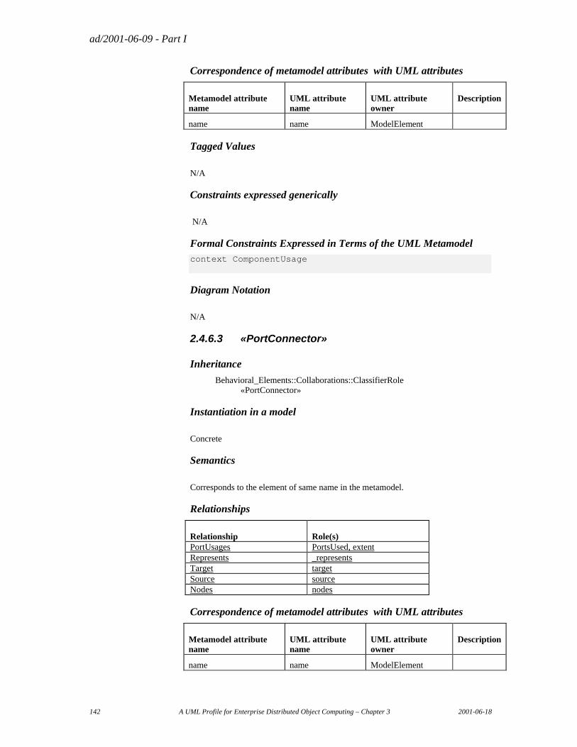
ad/2001-06-09 - Part I
142 A UML Profile for Enterprise Distributed Object Computing – Chapter 3 2001-06-18
Correspondence of metamodel attributes with UML attributes
Metamodel attribute name
UML attribute name
UML attribute owner
Description
name name ModelElement
Tagged Values
N/A
Constraints expressed generically
N/A
Formal Constraints Expressed in Terms of the UML Metamodel context ComponentUsage
Diagram Notation
N/A
2.4.6.3 «PortConnector»
Inheritance
Behavioral_Elements::Collaborations::ClassifierRole «PortConnector»
Instantiation in a model
Concrete
Semantics
Corresponds to the element of same name in the metamodel.
Relationships
Relationship Role(s) PortUsages PortsUsed, extent Represents _represents Target target Source source Nodes nodes
Correspondence of metamodel attributes with UML attributes
Metamodel attribute name
UML attribute name
UML attribute owner
Description
name name ModelElement
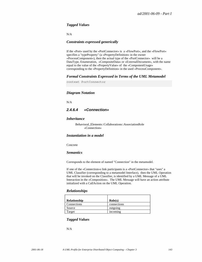
ad/2001-06-09 - Part I
2001-06-18 A UML Profile for Enterprise Distributed Object Computing – Chapter 3 143
Tagged Values
N/A
Constraints expressed generically
If the «Port» used by the «PortConnector» is a «FlowPort», and the «FlowPort» specifies a "typeProperty" (a «PropertyDefinition» in the owner «ProcessComponent»), then the actual type of the «PortConnector» will be a DataType, Enumeration, «CompositeData» or «ExternalDocument», with the name equal to the value of the «PropertyValue» of the «ComponentUsage» corresponding to the «PropertyDefinition» in the used «ProcessComponent».
Formal Constraints Expressed in Terms of the UML Metamodel context PortConnector
Diagram Notation
N/A
2.4.6.4 «Connection»
Inheritance
Behavioral_Elements::Collaborations::AssociationRole «Connection»
Instantiation in a model
Concrete
Semantics
Corresponds to the element of named "Connection" in the metamodel.
If one of the «Connection»s link participants is a «PortConnector» that "uses" a UML Classifier (corresponding to a metamodel Interface), then the UML Operation that will be invoked on the Classifier, is identified by a UML Message of a UML Interaction in the «Composition». The UML Message will have an action attribute initialized with a CallAction on the UML Operation.
Relationships
Relationship Role(s) Connections connections Source outgoing Target incoming
Tagged Values
N/A
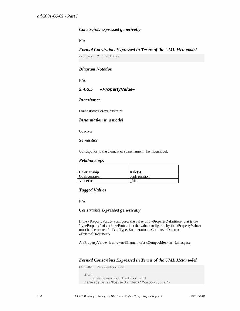
ad/2001-06-09 - Part I
144 A UML Profile for Enterprise Distributed Object Computing – Chapter 3 2001-06-18
Constraints expressed generically
N/A
Formal Constraints Expressed in Terms of the UML Metamodel context Connection
Diagram Notation
N/A
2.4.6.5 «PropertyValue»
Inheritance
Foundation::Core::Constraint
Instantiation in a model
Concrete
Semantics
Corresponds to the element of same name in the metamodel.
Relationships
Relationship Role(s) Configuration configuration ValueFor _fills
Tagged Values
N/A
Constraints expressed generically
If the «PropertyValue» configures the value of a «PropertyDefinition» that is the "typeProperty" of a «FlowPort», then the value configured by the «PropertyValue» must be the name of a DataType, Enumeration, «CompositeData» or «ExternalDocument».
A «PropertyValue» is an ownedElement of a «Composition» as Namespace.
Formal Constraints Expressed in Terms of the UML Metamodel context PropertyValue inv: namespace->notEmpty() and
namespace.isStereoKinded("Composition")
ad/2001-06-09 - Part I
2001-06-18 A UML Profile for Enterprise Distributed Object Computing – Chapter 3 145
Diagram Notation
N/A
2.4.6.6 «ContextualBinding»
Inheritance
Foundation::Core::Binding «ContextualBinding»
Instantiation in a model
Concrete
Semantics
Corresponds to the element of same name in the metamodel.
A «ContextualBinding» is an ownedElement of a «Composition».
The "client" of a ContextualBinding is a «ComponentUsage» in the «Composition».
The "supplier" of a ContextualBinding is a «ProcessComponent».
In the «Composition», the «ProcessComponent» will be used as the "uses" for the «ComponenUsage».
Relationships
N/A
Tagged Values
N/A
Constraints expressed generically
Formal Constraints Expressed in Terms of the UML Metamodel context ContextualBinding
Diagram Notation
N/A
2.4.6.7 «CommunityProcess»
Inheritance
ModelManagement::Subsystem «CommunityProcess»
ad/2001-06-09 - Part I
146 A UML Profile for Enterprise Distributed Object Computing – Chapter 3 2001-06-18
Instantiation in a model
Concrete
Semantics
Corresponds to the element of same name in the metamodel.
Relationships
N/A
Tagged Values
N/A
Constraints expressed generically
Formal Constraints Expressed in Terms of the UML Metamodel context CommunityProcess
Diagram Notation
N/A
2.4.7 DocumentModel «profile» Package
The metamodel elements named Attribute, DataType and Enumeration correspond to the UML model elements of the same name and are not stereotyped.
The metaattribute named "initialValue" of the metamodel Attribute, corresponds to the attribute of same name of UML Attribute.
The metaattribute named "required" and "many" of the metamodel Attribute, are combined as a UML Multiplicity. The MultiplicityRange, will have the "lower" attribute value equal to 0, if the corresponding metamodel Attribute has the "required" meta-attribute equal to false, and greater than 0, if "required" is true. The MultiplicityRange will have the "upper" attribute value equal to 1, if the corresponding metamodel Attribute has the "many" meta-attribute equal to false, and and greater than 1, if "many" is true.
The metamodel element named Enumeration has a metaattribute named "initial" and type EnumerationValue. In the UML Profile, the responsibility of specifying an initial value, is delegated to the UML Attribute with type equal to the Enumeration. The initialValue attribute, of type Expression, in UML Attribute will be used to specify the default initial value of Enumeration.
The metamodel element named Enumeration Value corresponds to the UML model element named EnumerationLiteral.
The metamodel Attribute and UML Attribute correspond to each other completely, with the exception of the meta-attribute named "isByValue".
To represent "isByValue", a TaggedDefinition of same name and type Boolean is defined, to be applied on UML Attribute.
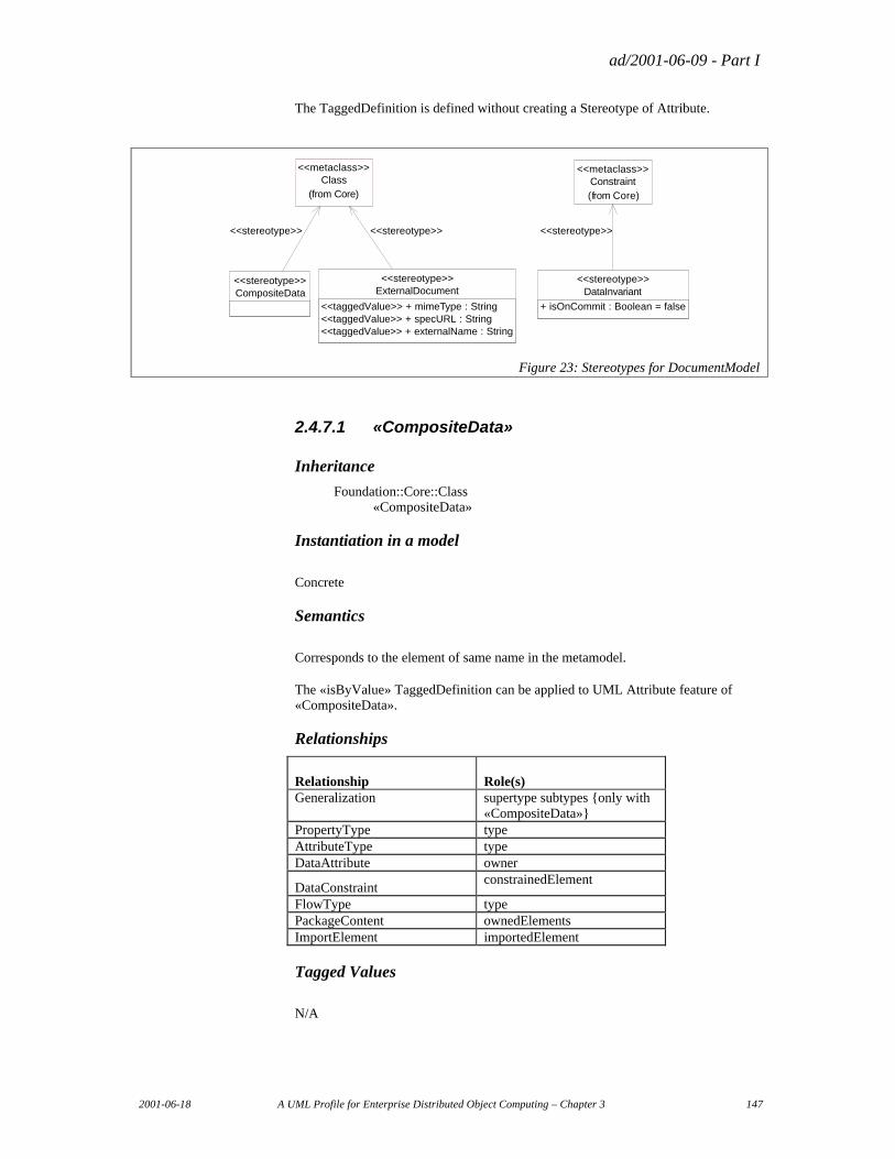
ad/2001-06-09 - Part I
2001-06-18 A UML Profile for Enterprise Distributed Object Computing – Chapter 3 147
The TaggedDefinition is defined without creating a Stereotype of Attribute.
CompositeData<<stereotype>>
Class(from Core)
<<metaclass>>
<<stereotype>>
DataInvariant<<stereotype>>
+ isOnCommit : Boolean = false
Constraint(from Core)
<<metaclass>>
<<stereotype>>
ExternalDocument<<stereotype>>
<<taggedValue>> + mimeType : String<<taggedValue>> + specURL : String<<taggedValue>> + externalName : String
<<stereotype>>
Figure 23: Stereotypes for DocumentModel
2.4.7.1 «CompositeData»
Inheritance
Foundation::Core::Class «CompositeData»
Instantiation in a model
Concrete
Semantics
Corresponds to the element of same name in the metamodel.
The «isByValue» TaggedDefinition can be applied to UML Attribute feature of «CompositeData».
Relationships
Relationship Role(s) Generalization supertype subtypes {only with
«CompositeData»} PropertyType type AttributeType type DataAttribute owner
DataConstraint constrainedElement
FlowType type PackageContent ownedElements ImportElement importedElement
Tagged Values
N/A
ad/2001-06-09 - Part I
148 A UML Profile for Enterprise Distributed Object Computing – Chapter 3 2001-06-18
Constraints expressed generically
The supertype of an «CompositeData» must be a «CompositeData».
The type of Attributes of «CompositeData» will be a DataType, an Enumeration, or a Class stereotyped as «CompositeData», or a DataType stereotyped «ExternalDocument».
Formal Constraints Expressed in Terms of the UML Metamodel context CompositeData inv: supertype->isEmpty() or
supertype.isStereoKinded("CompositeData") inv: feature->select( aFeature : Feature |
aFeature.isOCLTypeOf( Attribute)) ->collect( aFeature : Feature | aFeature.oclAsType(
Attribute).type) ->forAll( aClassifier : Classifier | aClassifier.isOclKindOf( DataType) or aClassifier.isOclKindOf( Enumeration) or aClassifier.isStereoKinded( "CompositeData") or aClassifier.isStereoKinded( "ExternalDocument"))
Diagram Notation
N/A
2.4.7.2 "isByValue" Tagged Definition
The metamodel Attributes and UML Attributes correspond to each other completely, with the exception of the meta-attribute named "isByValue".
To represent the metamodel attribute named "isByValue", a Tagged Definition of named "isByValue" and type Boolean is defined, to be applied on UML Attribute.
The Tagged Definition is defined without creating a Stereotype of Attribute.
Tagged Value name Type Multiplicity Description
isByValue Boolean 0..1 default = true
2.4.7.3 «DataInvariant»
Inheritance
Foundation::Core::Constraint «DataInvariant»
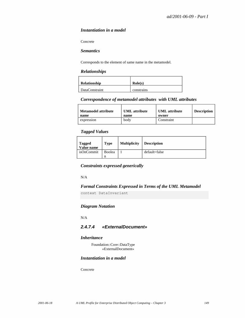
ad/2001-06-09 - Part I
2001-06-18 A UML Profile for Enterprise Distributed Object Computing – Chapter 3 149
Instantiation in a model
Concrete
Semantics
Corresponds to the element of same name in the metamodel.
Relationships
Relationship Role(s)
DataConstraint constrains
Correspondence of metamodel attributes with UML attributes
Metamodel attribute name
UML attribute name
UML attribute owner
Description
expression body Constraint
Tagged Values
Tagged Value name
Type Multiplicity Description
isOnCommit Boolean
1 default=false
Constraints expressed generically
N/A
Formal Constraints Expressed in Terms of the UML Metamodel context DataInvariant
Diagram Notation
N/A
2.4.7.4 «ExternalDocument»
Inheritance
Foundation::Core::DataType «ExternalDocument»
Instantiation in a model
Concrete
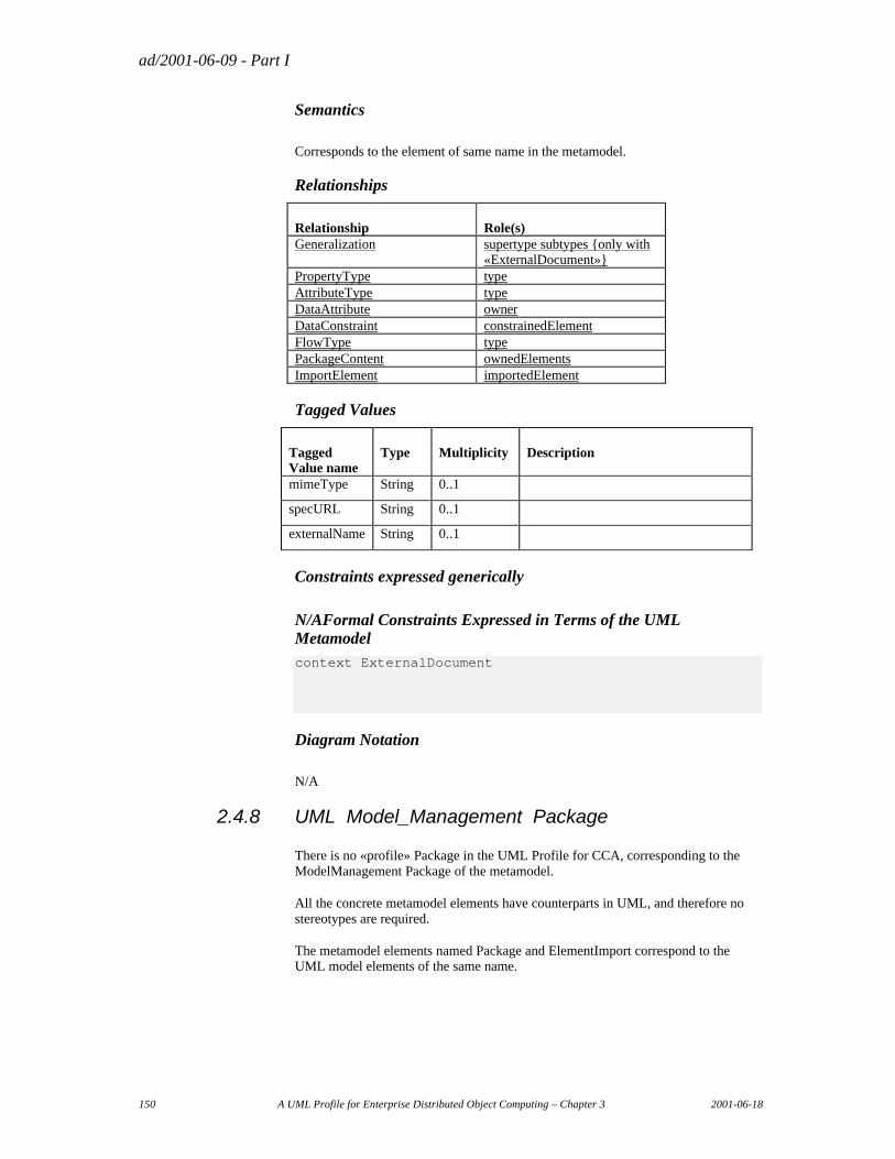
ad/2001-06-09 - Part I
150 A UML Profile for Enterprise Distributed Object Computing – Chapter 3 2001-06-18
Semantics
Corresponds to the element of same name in the metamodel.
Relationships
Relationship Role(s) Generalization supertype subtypes {only with
«ExternalDocument»} PropertyType type AttributeType type DataAttribute owner DataConstraint constrainedElement FlowType type PackageContent ownedElements ImportElement importedElement
Tagged Values
Tagged Value name
Type Multiplicity Description
mimeType String 0..1
specURL String 0..1
externalName String 0..1
Constraints expressed generically
N/AFormal Constraints Expressed in Terms of the UML Metamodel context ExternalDocument
Diagram Notation
N/A
2.4.8 UML Model_Management Package
There is no «profile» Package in the UML Profile for CCA, corresponding to the ModelManagement Package of the metamodel.
All the concrete metamodel elements have counterparts in UML, and therefore no stereotypes are required.
The metamodel elements named Package and ElementImport correspond to the UML model elements of the same name.
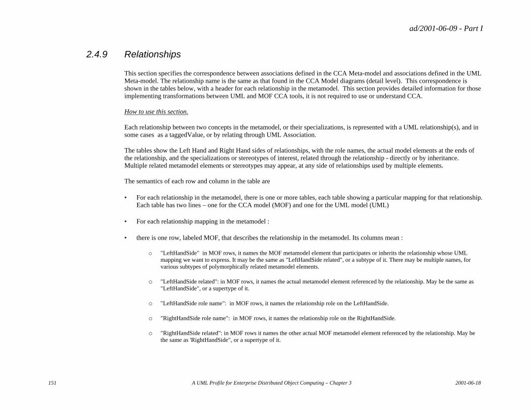
ad/2001-06-09 - Part I
151 A UML Profile for Enterprise Distributed Object Computing – Chapter 3 2001-06-18
2.4.9 Relationships
This section specifies the correspondence between associations defined in the CCA Meta-model and associations defined in the UML Meta-model. The relationship name is the same as that found in the CCA Model diagrams (detail level). This correspondence is shown in the tables below, with a header for each relationship in the metamodel. This section provides detailed information for those implementing transformations between UML and MOF CCA tools, it is not required to use or understand CCA.
How to use this section.
Each relationship between two concepts in the metamodel, or their specializations, is represented with a UML relationship(s), and in some cases as a taggedValue, or by relating through UML Association.
The tables show the Left Hand and Right Hand sides of relationships, with the role names, the actual model elements at the ends of the relationship, and the specializations or stereotypes of interest, related through the relationship - directly or by inheritance. Multiple related metamodel elements or stereotypes may appear, at any side of relationships used by multiple elements.
The semantics of each row and column in the table are
• For each relationship in the metamodel, there is one or more tables, each table showing a particular mapping for that relationship. Each table has two lines – one for the CCA model (MOF) and one for the UML model (UML)
• For each relationship mapping in the metamodel :
• there is one row, labeled MOF, that describes the relationship in the metamodel. Its columns mean :
o "LeftHandSide" in MOF rows, it names the MOF metamodel element that participates or inherits the relationship whose UML mapping we want to express. It may be the same as "LeftHandSide related", or a subtype of it. There may be multiple names, for various subtypes of polymorphically related metamodel elements.
o "LeftHandSide related": in MOF rows, it names the actual metamodel element referenced by the relationship. May be the same as "LeftHandSide", or a supertype of it.
o "LeftHandSide role name": in MOF rows, it names the relationship role on the LeftHandSide.
o "RightHandSide role name": in MOF rows, it names the relationship role on the RightHandSide.
o "RightHandSide related": in MOF rows it names the other actual MOF metamodel element referenced by the relationship. May be the same as 'RightHandSide", or a supertype of it.
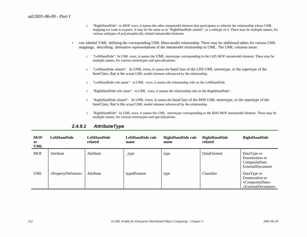
ad/2001-06-09 - Part I
152 A UML Profile for Enterprise Distributed Object Computing – Chapter 3 2001-06-18
o "RightHandSide": in MOF rows, it names the other metamodel element that participates or inherits the relationship whose UML mapping we want to express. It may be the same as in "RightHandSide related", or a subtype of it. There may be multiple names, for various subtypes of polymorphically related metamodel elements.
• row labeled 'UML' defining the corresponding UML Meta-model relationship. There may be additional tables for various UML mappings, describing alternative representations of the metamodel relationship in UML. The UML columns mean :
o "LeftHandSide": In UML rows, it names the UML stereotype corresponding to the LHS MOF metamodel element. There may be multiple names, for various stereotypes and specializations.
o "LeftHandSide related": In UML rows, it names the baseClass of the LHS UML stereotype, or the supertype of the baseClass, that is the actual UML model element referenced by the relationship.
o "LeftHandSide role name": in UML rows, it names the relationship role on the LeftHandSide
o "RightHandSide role name": in UML rows, it names the relationship role on the RightHandSide '.
o "RightHandSide related": In UML rows, it names the baseClass of the RHS UML stereotype, or the supertype of the baseClass, that is the actual UML model element referenced by the relationship.
o "RightHandSide": In UML rows, it names the UML stereotype corresponding to the RHS MOF metamodel element. There may be multiple names, for various stereotypes and specializations.
2.4.9.1 AttributeType
MOF or UML
LeftHandSide LeftHandSide related
LeftHandSide role name
RightHandSide role name
RightHandSide related
RightHandSide
MOF Attribute Attribute _type type DataElement DataType or Enumeration or CompositeData ExternalDocument
UML «PropertyDefintion» Attribute typedFeature type Classifier DataType or Enumeration or «CompositeData» «ExternalDocument»
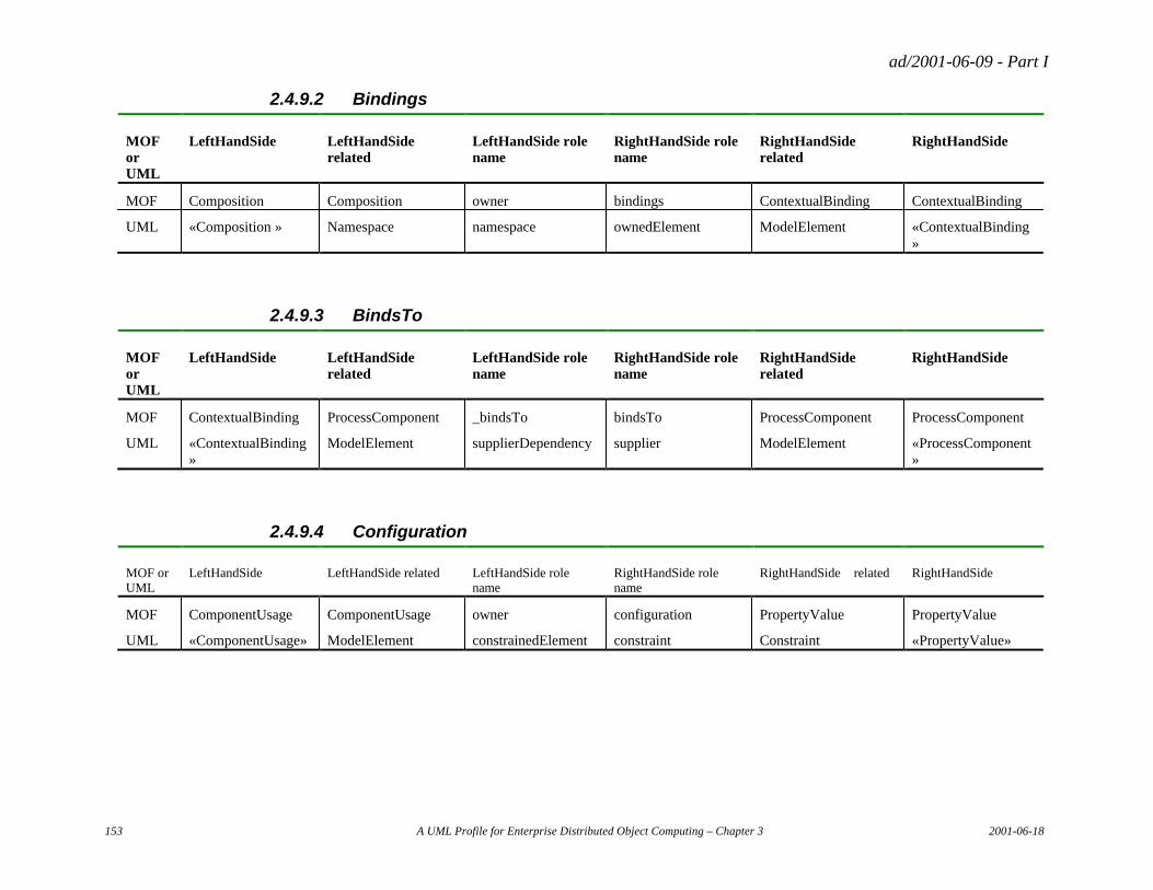
ad/2001-06-09 - Part I
153 A UML Profile for Enterprise Distributed Object Computing – Chapter 3 2001-06-18
2.4.9.2 Bindings
MOF or UML
LeftHandSide LeftHandSide related
LeftHandSide role name
RightHandSide role name
RightHandSide related
RightHandSide
MOF Composition Composition owner bindings ContextualBinding ContextualBinding
UML «Composition » Namespace namespace ownedElement ModelElement «ContextualBinding»
2.4.9.3 BindsTo
MOF or UML
LeftHandSide LeftHandSide related
LeftHandSide role name
RightHandSide role name
RightHandSide related
RightHandSide
MOF ContextualBinding ProcessComponent _bindsTo bindsTo ProcessComponent ProcessComponent
UML «ContextualBinding»
ModelElement supplierDependency supplier ModelElement «ProcessComponent»
2.4.9.4 Configuration
MOF or UML
LeftHandSide LeftHandSide related LeftHandSide role name
RightHandSide role name
RightHandSide related RightHandSide
MOF ComponentUsage ComponentUsage owner configuration PropertyValue PropertyValue
UML «ComponentUsage» ModelElement constrainedElement constraint Constraint «PropertyValue»
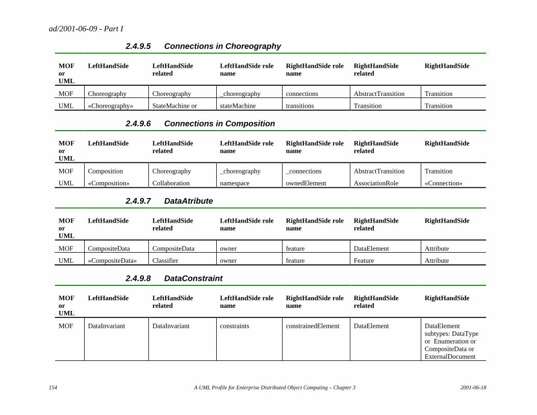
ad/2001-06-09 - Part I
154 A UML Profile for Enterprise Distributed Object Computing – Chapter 3 2001-06-18
2.4.9.5 Connections in Choreography
MOF or UML
LeftHandSide LeftHandSide related
LeftHandSide role name
RightHandSide role name
RightHandSide related
RightHandSide
MOF Choreography Choreography _choreography connections AbstractTransition Transition
UML «Choreography» StateMachine or stateMachine transitions Transition Transition
2.4.9.6 Connections in Composition
MOF or UML
LeftHandSide LeftHandSide related
LeftHandSide role name
RightHandSide role name
RightHandSide related
RightHandSide
MOF Composition Choreography _choreography _connections AbstractTransition Transition
UML «Composition» Collaboration namespace ownedElement AssociationRole «Connection»
2.4.9.7 DataAtribute
MOF or UML
LeftHandSide LeftHandSide related
LeftHandSide role name
RightHandSide role name
RightHandSide related
RightHandSide
MOF CompositeData CompositeData owner feature DataElement Attribute
UML «CompositeData» Classifier owner feature Feature Attribute
2.4.9.8 DataConstraint
MOF or UML
LeftHandSide LeftHandSide related
LeftHandSide role name
RightHandSide role name
RightHandSide related
RightHandSide
MOF DataInvariant DataInvariant constraints constrainedElement DataElement DataElement subtypes: DataType or Enumeration or CompositeData or ExternalDocument

ad/2001-06-09 - Part I
155 A UML Profile for Enterprise Distributed Object Computing – Chapter 3 2001-06-18
MOF or UML
LeftHandSide LeftHandSide related
LeftHandSide role name
RightHandSide role name
RightHandSide related
RightHandSide
UML «DataInvariant» Constraint constraint constrainedElement ModelElement DataType or Enumeration or «CompositeData» or «ExternalDocument»
2.4.9.9 DataGeneralization
MOF or UML
LeftHandSide LeftHandSide related
LeftHandSide role name
RightHandSide role name
RightHandSide related
RightHandSide
MOF CompositeData CompositeData supertype subtypes CompositeData CompositeData
UML «CompositeData» GeneralizableElement generalization.parent specialization. child GeneralizableElement «CompositeData»
2.4.9.10 Fills
MOF or UML
LeftHandSide LeftHandSide related
LeftHandSide role name
RightHandSide role name
RightHandSide related
RightHandSide
MOF ContextualBinding ProcessComponent _fills fills ProcessComponent ProcessComponent
UML «ContextualBinding»
ModelElement clientDeendency fills ModelElement «ProcessComponent»
2.4.9.11 FlowType
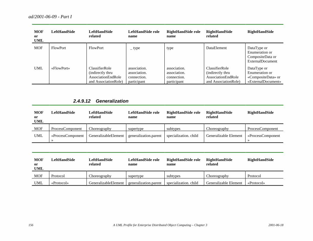
ad/2001-06-09 - Part I
156 A UML Profile for Enterprise Distributed Object Computing – Chapter 3 2001-06-18
MOF or UML
LeftHandSide LeftHandSide related
LeftHandSide role name
RightHandSide role name
RightHandSide related
RightHandSide
MOF FlowPort FlowPort _ type type DataElement DataType or Enumeration or CompositeData or ExternalDocument
UML «FlowPort» ClassifierRole (indirectly thru AssociationEndRole and AssociationRole)
association. association. connection. participant
association. association. connection. participant
ClassifierRole (indirectly thru AssociationEndRole and AssociationRole)
DataType or Enumeration or «CompositeData» or «ExternalDocument»
2.4.9.12 Generalization
MOF or UML
LeftHandSide LeftHandSide related
LeftHandSide role name
RightHandSide role name
RightHandSide related
RightHandSide
MOF ProcessComponent Choreography supertype subtypes Choreography ProcessComponent
UML «ProcessComponent»
GeneralizableElement generalization.parent specialization. child Generalizable Element «ProcessComponent»
MOF or UML
LeftHandSide LeftHandSide related
LeftHandSide role name
RightHandSide role name
RightHandSide related
RightHandSide
MOF Protocol Choreography supertype subtypes Choreography Protocol
UML «Protocol» GeneralizableElement generalization.parent specialization. child Generalizable Element «Protocol»
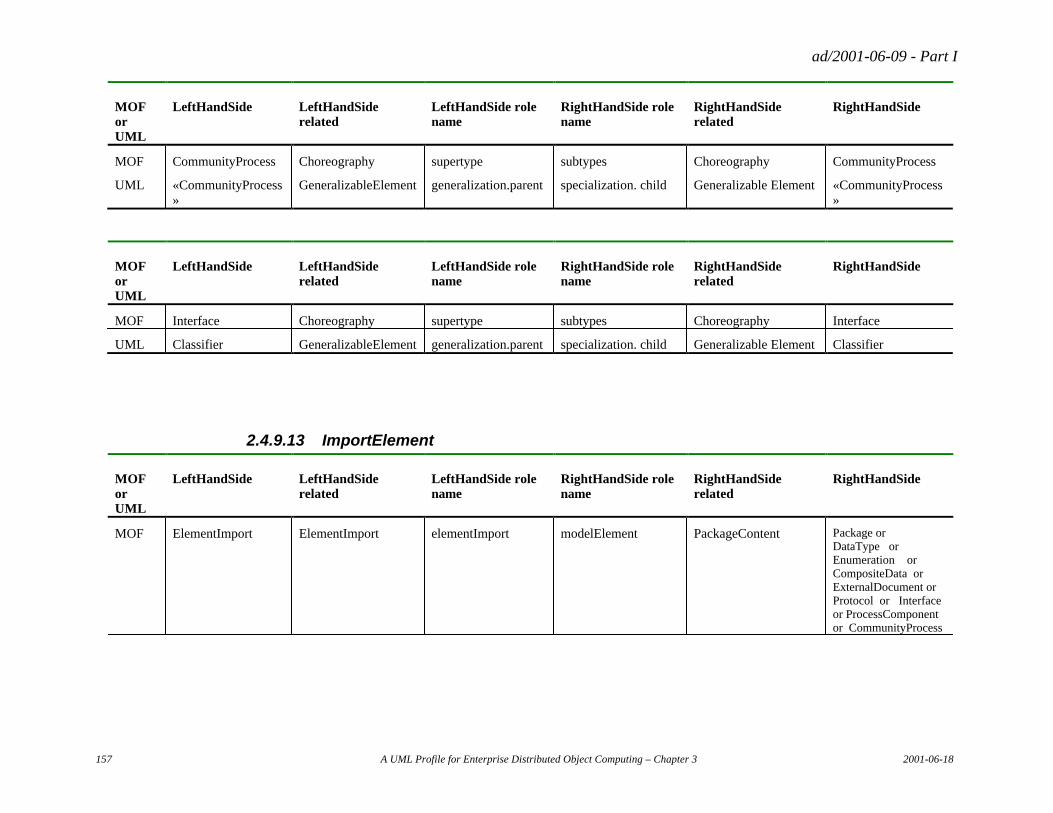
ad/2001-06-09 - Part I
157 A UML Profile for Enterprise Distributed Object Computing – Chapter 3 2001-06-18
MOF or UML
LeftHandSide LeftHandSide related
LeftHandSide role name
RightHandSide role name
RightHandSide related
RightHandSide
MOF CommunityProcess Choreography supertype subtypes Choreography CommunityProcess
UML «CommunityProcess»
GeneralizableElement generalization.parent specialization. child Generalizable Element «CommunityProcess»
MOF or UML
LeftHandSide LeftHandSide related
LeftHandSide role name
RightHandSide role name
RightHandSide related
RightHandSide
MOF Interface Choreography supertype subtypes Choreography Interface
UML Classifier GeneralizableElement generalization.parent specialization. child Generalizable Element Classifier
2.4.9.13 ImportElement
MOF or UML
LeftHandSide LeftHandSide related
LeftHandSide role name
RightHandSide role name
RightHandSide related
RightHandSide
MOF ElementImport ElementImport elementImport modelElement PackageContent Package or DataType or Enumeration or CompositeData or ExternalDocument or Protocol or Interface or ProcessComponent or CommunityProcess
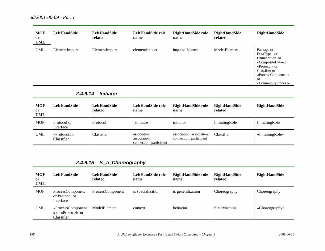
ad/2001-06-09 - Part I
158 A UML Profile for Enterprise Distributed Object Computing – Chapter 3 2001-06-18
MOF or UML
LeftHandSide LeftHandSide related
LeftHandSide role name
RightHandSide role name
RightHandSide related
RightHandSide
UML ElementImport ElementImport elementImport importedElement ModelElement Package or DataType or Enumeration or «CompositeData» or «Protocol» or Classifier or «ProcessComponent» or «CommunityProcess»
2.4.9.14 Initiator
MOF or UML
LeftHandSide LeftHandSide related
LeftHandSide role name
RightHandSide role name
RightHandSide related
RightHandSide
MOF Protocol or Interface
Protocol _initiator initiator InitiatingRole InitiatingRole
UML «Protocol» or Classifier
Classifier association. association. connection. participant
association. association. connection. participant
Classifier «InitiatingRole»
2.4.9.15 Is_a_Choreography
MOF or UML
LeftHandSide LeftHandSide related
LeftHandSide role name
RightHandSide role name
RightHandSide related
RightHandSide
MOF ProcessComponent or Protocol or Interface
ProcessComponent is specialization is generalization Choreography Choreography
UML «ProcessComponent» or «Protocol» or Classifier
ModelElement context behavior StateMachine «Choreography»
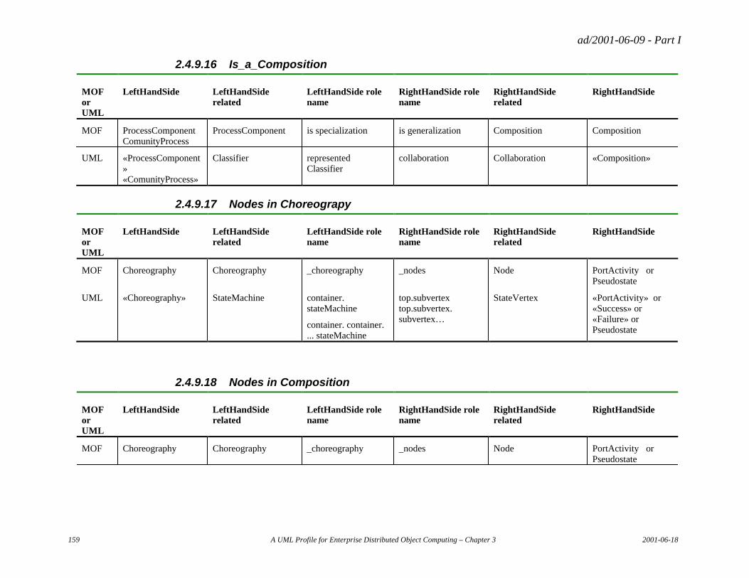
ad/2001-06-09 - Part I
159 A UML Profile for Enterprise Distributed Object Computing – Chapter 3 2001-06-18
2.4.9.16 Is_a_Composition
MOF or UML
LeftHandSide LeftHandSide related
LeftHandSide role name
RightHandSide role name
RightHandSide related
RightHandSide
MOF ProcessComponent ComunityProcess
ProcessComponent is specialization is generalization Composition Composition
UML «ProcessComponent» «ComunityProcess»
Classifier represented Classifier
collaboration Collaboration «Composition»
2.4.9.17 Nodes in Choreograpy
MOF or UML
LeftHandSide LeftHandSide related
LeftHandSide role name
RightHandSide role name
RightHandSide related
RightHandSide
MOF Choreography Choreography _choreography _nodes Node PortActivity or Pseudostate
UML «Choreography» StateMachine container. stateMachine
container. container. ... stateMachine
top.subvertex top.subvertex. subvertex…
StateVertex «PortActivity» or «Success» or «Failure» or Pseudostate
2.4.9.18 Nodes in Composition
MOF or UML
LeftHandSide LeftHandSide related
LeftHandSide role name
RightHandSide role name
RightHandSide related
RightHandSide
MOF Choreography Choreography _choreography _nodes Node PortActivity or Pseudostate
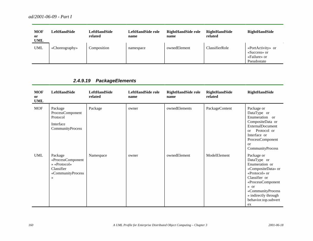
ad/2001-06-09 - Part I
160 A UML Profile for Enterprise Distributed Object Computing – Chapter 3 2001-06-18
MOF or UML
LeftHandSide LeftHandSide related
LeftHandSide role name
RightHandSide role name
RightHandSide related
RightHandSide
UML «Choreography» Composition namespace ownedElement ClassifierRole «PortActivity» or «Success» or «Failure» or Pseudostate
2.4.9.19 PackageElements
MOF or UML
LeftHandSide LeftHandSide related
LeftHandSide role name
RightHandSide role name
RightHandSide related
RightHandSide
MOF Package ProcessComponent Protocol
Interface CommunityProcess
Package owner ownedElements PackageContent Package or DataType or Enumeration or CompositeData or ExternalDocument or Protocol or Interface or ProcessComponent or CommunityProcess
UML Package «ProcessComponent» «Protocol» Classifier «CommunityProcess»
Namespace owner ownedElement ModelElement Package or DataType or Enumeration or «CompositeData» or «Protocol» or Classifier or «ProcessComponent» or «CommunityProcess» indirectly through behavior.top.subvertex
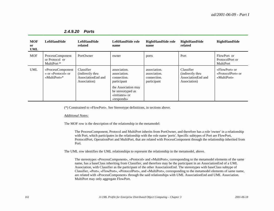
ad/2001-06-09 - Part I
161 A UML Profile for Enterprise Distributed Object Computing – Chapter 3 2001-06-18
2.4.9.20 Ports
MOF or UML
LeftHandSide LeftHandSide related
LeftHandSide role name
RightHandSide role name
RightHandSide related
RightHandSide
MOF ProcessComponent or Protocol or MultiPort *
PortOwner owner ports Port FlowPort or ProtocolPort or MultiPort
UML «ProcessComponent» or «Protocol» or «MultiPort»*
Classifier (indirectly thru AssociationEnd and Association)
association. association. connection. participant
the Association may be stereotyped as «initiates» or «responds»
association. association. connection. participant
Classifier (indirectly thru AssociationEnd and Association)
«FlowPort» or «ProtocolPort» or «MultiPort»
(*) Constrained to «FlowPort». See Stereotype definitions, in sections above.
Additional Notes:
The MOF row is the description of the relationship in the metamodel:
The ProcessComponent, Protocol and MultiPort inherits from PortOwner, and therefore has a role 'owner' in a relationship with Port, which participates in the relationship with the role name 'ports'. Specific subtypes of Port are FlowPort, ProtocolPort, OperationPort and MultiPort, that are related with ProcessComponent through the relationship inherited from Port.
The UML row identifies the UML relationships to represent the relationship in the metamodel, above.
The stereotypes «ProcessComponent», «Protocol» and «MultiPort», corresponding to the metamodel elements of the same name, has a baseClass inheriting from Classifier, and therefore may be the participant in an AssociationEnd of a UML Association, with Classifier as the participant of the other AssociationEnd. The stereotypes with baseClass subtype of Classifier, «Port», «FlowPort», «ProtocolPort», and «MultiPort», corresponding to the metamodel elements of same name, are related with «ProcessComponent» through the said relationships with UML AssociationEnd and UML Association. MultiPort may only aggregate FlowPort.
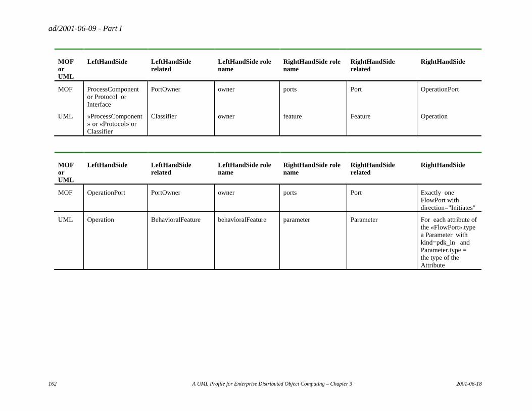
ad/2001-06-09 - Part I
162 A UML Profile for Enterprise Distributed Object Computing – Chapter 3 2001-06-18
MOF or UML
LeftHandSide LeftHandSide related
LeftHandSide role name
RightHandSide role name
RightHandSide related
RightHandSide
MOF ProcessComponent or Protocol or Interface
PortOwner owner ports Port OperationPort
UML «ProcessComponent» or «Protocol» or Classifier
Classifier owner feature Feature Operation
MOF or UML
LeftHandSide LeftHandSide related
LeftHandSide role name
RightHandSide role name
RightHandSide related
RightHandSide
MOF OperationPort PortOwner owner ports Port Exactly one FlowPort with direction="Initiates"
UML Operation BehavioralFeature behavioralFeature parameter Parameter For each attribute of the «FlowPort».type a Parameter with kind=pdk_in and Parameter.type = the type of the Attribute
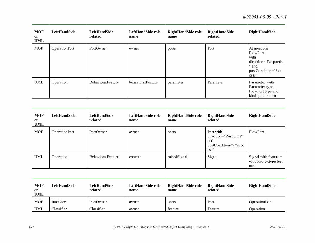
ad/2001-06-09 - Part I
163 A UML Profile for Enterprise Distributed Object Computing – Chapter 3 2001-06-18
MOF or UML
LeftHandSide LeftHandSide related
LeftHandSide role name
RightHandSide role name
RightHandSide related
RightHandSide
MOF OperationPort PortOwner owner ports Port At most one FlowPort with direction="Responds" and postCondition="Success"
UML Operation BehavioralFeature behavioralFeature parameter Parameter Parameter with Parameter.type= FlowPort.type and kind=pdk_return
MOF or UML
LeftHandSide LeftHandSide related
LeftHandSide role name
RightHandSide role name
RightHandSide related
RightHandSide
MOF OperationPort PortOwner owner ports Port with direction="Responds" and postCondition<>"Success"
FlowPort
UML Operation BehavioralFeature context raisedSignal Signal Signal with feature = «FlowPort».type.feature
MOF or UML
LeftHandSide LeftHandSide related
LeftHandSide role name
RightHandSide role name
RightHandSide related
RightHandSide
MOF Interface PortOwner owner ports Port OperationPort
UML Classifier Classifier owner feature Feature Operation
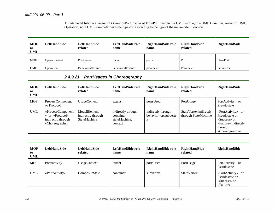
ad/2001-06-09 - Part I
164 A UML Profile for Enterprise Distributed Object Computing – Chapter 3 2001-06-18
A metamodel Interface, owner of OperationPort, owner of FlowPort, map in the UML Profile, to a UML Classifier, owner of UML Operation, with UML Parameter with the type corresponding to the type of the metamodel FlowPort.
MOF or UML
LeftHandSide LeftHandSide related
LeftHandSide role name
RightHandSide role name
RightHandSide related
RightHandSide
MOF OperationPort PortOwner owner ports Port FlowPort
UML Operation BehavioralFeature behavioralFeature parameter Parameter Parameter
2.4.9.21 PortUsages in Choreography
MOF or UML
LeftHandSide LeftHandSide related
LeftHandSide role name
RightHandSide role name
RightHandSide related
RightHandSide
MOF ProcessComponent or Protocol
UsageContext extent portsUsed PortUsage PortActivity or Pseudostate
UML «ProcessComponent» or «Protocol» indirectly through «Choreography»
ModelElement indirectly through StateMachine
indirectly through container. stateMachine. context
indirectly through behavior.top.subvertex
StateVertex indirectly through StateMachine
«PortActivity» or Pseudostate or «Success» or «Failure» indirectly through «Choreography»
MOF or UML
LeftHandSide LeftHandSide related
LeftHandSide role name
RightHandSide role name
RightHandSide related
RightHandSide
MOF PortActivity UsageContext extent portsUsed PortUsage PortActivity or Pseudostate
UML «PortActivity» CompositeState container subvertex StateVertex «PortActivity» or Pseudostate or «Success» or «Failure»
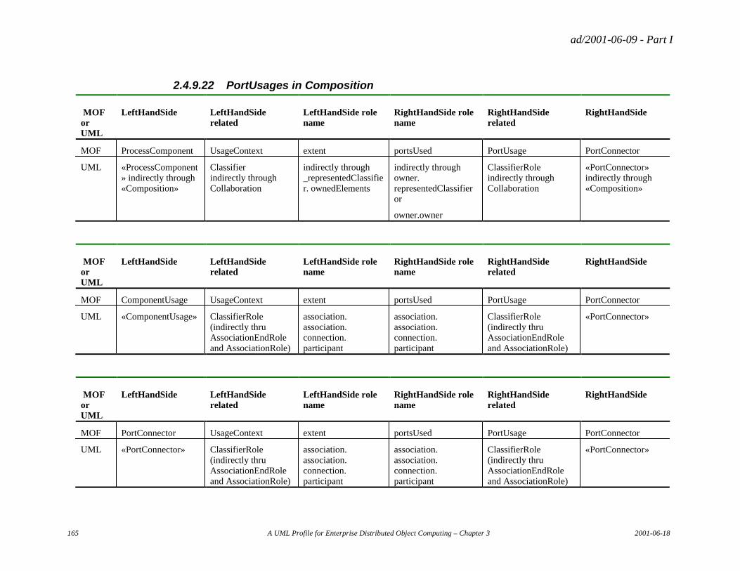
ad/2001-06-09 - Part I
165 A UML Profile for Enterprise Distributed Object Computing – Chapter 3 2001-06-18
2.4.9.22 PortUsages in Composition
MOF or UML
LeftHandSide LeftHandSide related
LeftHandSide role name
RightHandSide role name
RightHandSide related
RightHandSide
MOF ProcessComponent UsageContext extent portsUsed PortUsage PortConnector
UML «ProcessComponent» indirectly through «Composition»
Classifier indirectly through Collaboration
indirectly through _representedClassifier. ownedElements
indirectly through owner. representedClassifier or
owner.owner
ClassifierRole indirectly through Collaboration
«PortConnector» indirectly through «Composition»
MOF or UML
LeftHandSide LeftHandSide related
LeftHandSide role name
RightHandSide role name
RightHandSide related
RightHandSide
MOF ComponentUsage UsageContext extent portsUsed PortUsage PortConnector
UML «ComponentUsage» ClassifierRole (indirectly thru AssociationEndRole and AssociationRole)
association. association. connection. participant
association. association. connection. participant
ClassifierRole (indirectly thru AssociationEndRole and AssociationRole)
«PortConnector»
MOF or UML
LeftHandSide LeftHandSide related
LeftHandSide role name
RightHandSide role name
RightHandSide related
RightHandSide
MOF PortConnector UsageContext extent portsUsed PortUsage PortConnector
UML «PortConnector» ClassifierRole (indirectly thru AssociationEndRole and AssociationRole)
association. association. connection. participant
association. association. connection. participant
ClassifierRole (indirectly thru AssociationEndRole and AssociationRole)
«PortConnector»
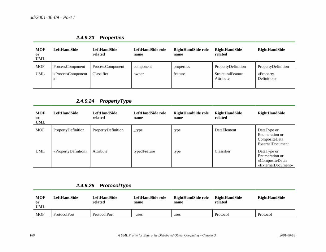
ad/2001-06-09 - Part I
166 A UML Profile for Enterprise Distributed Object Computing – Chapter 3 2001-06-18
2.4.9.23 Properties
MOF or UML
LeftHandSide LeftHandSide related
LeftHandSide role name
RightHandSide role name
RightHandSide related
RightHandSide
MOF ProcessComponent ProcessComponent component properties PropertyDefinition PropertyDefinition
UML «ProcessComponent»
Classifier owner feature StructuralFeature Attribute
«Property Definition»
2.4.9.24 PropertyType
MOF or UML
LeftHandSide LeftHandSide related
LeftHandSide role name
RightHandSide role name
RightHandSide related
RightHandSide
MOF PropertyDefinition PropertyDefinition _type type DataElement DataType or Enumeration or CompositeData ExternalDocument
UML «PropertyDefintion» Attribute typedFeature type Classifier DataType or Enumeration or «CompositeData» «ExternalDocument»
2.4.9.25 ProtocolType
MOF or UML
LeftHandSide LeftHandSide related
LeftHandSide role name
RightHandSide role name
RightHandSide related
RightHandSide
MOF ProtocolPort ProtocolPort _uses uses Protocol Protocol
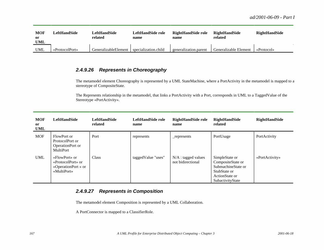
ad/2001-06-09 - Part I
167 A UML Profile for Enterprise Distributed Object Computing – Chapter 3 2001-06-18
MOF or UML
LeftHandSide LeftHandSide related
LeftHandSide role name
RightHandSide role name
RightHandSide related
RightHandSide
UML «ProtocolPort» GeneralizableElement specialization.child generalization.parent Generalizable Element «Protocol»
2.4.9.26 Represents in Choreography
The metamodel element Choreography is represented by a UML StateMachine, where a PortActivity in the metamodel is mapped to a stereotype of CompositeState.
The Represents relationship in the metamodel, that links a PortActivity with a Port, corresponds in UML to a TaggedValue of the Stereotype «PortActivity».
MOF or UML
LeftHandSide LeftHandSide related
LeftHandSide role name
RightHandSide role name
RightHandSide related
RightHandSide
MOF FlowPort or ProtocolPort or OperationPort or MultiPort
Port represents _represents PortUsage PortActivity
UML «FlowPort» or «ProtocolPort» or «OperationPort » or «MultiPort»
Class taggedValue "uses" N/A : tagged values not bidirectional
SimpleState or CompositeState or SubmachineState or StubState or ActionState or SubactivityState
«PortActivity»
2.4.9.27 Represents in Composition
The metamodel element Composition is represented by a UML Collaboration.
A PortConnector is mapped to a ClassifierRole.
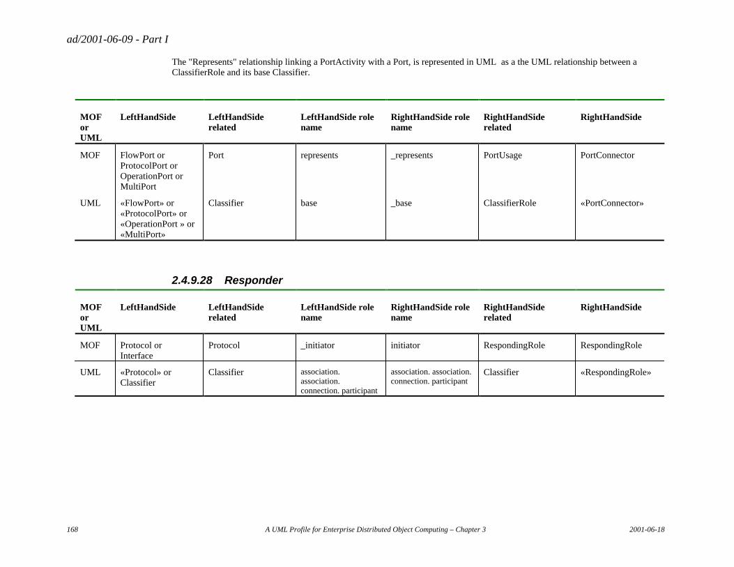
ad/2001-06-09 - Part I
168 A UML Profile for Enterprise Distributed Object Computing – Chapter 3 2001-06-18
The "Represents" relationship linking a PortActivity with a Port, is represented in UML as a the UML relationship between a ClassifierRole and its base Classifier.
MOF or UML
LeftHandSide LeftHandSide related
LeftHandSide role name
RightHandSide role name
RightHandSide related
RightHandSide
MOF FlowPort or ProtocolPort or OperationPort or MultiPort
Port represents _represents PortUsage PortConnector
UML «FlowPort» or «ProtocolPort» or «OperationPort » or «MultiPort»
Classifier base _base ClassifierRole «PortConnector»
2.4.9.28 Responder
MOF or UML
LeftHandSide LeftHandSide related
LeftHandSide role name
RightHandSide role name
RightHandSide related
RightHandSide
MOF Protocol or Interface
Protocol _initiator initiator RespondingRole RespondingRole
UML «Protocol» or Classifier
Classifier association. association. connection. participant
association. association. connection. participant
Classifier «RespondingRole»
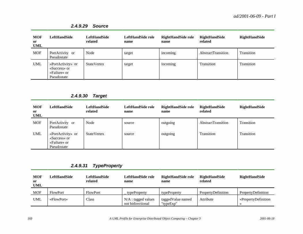
ad/2001-06-09 - Part I
169 A UML Profile for Enterprise Distributed Object Computing – Chapter 3 2001-06-18
2.4.9.29 Source
MOF or UML
LeftHandSide LeftHandSide related
LeftHandSide role name
RightHandSide role name
RightHandSide related
RightHandSide
MOF PortActivity or Pseudostate
Node target incoming AbstractTransition Transition
UML «PortActivity» or «Success» or «Failure» or Pseudostate
StateVertex target incoming Transition Transition
2.4.9.30 Target
MOF or UML
LeftHandSide LeftHandSide related
LeftHandSide role name
RightHandSide role name
RightHandSide related
RightHandSide
MOF PortActivity or Pseudostate
Node source outgoing AbstractTransition Transition
UML «PortActivity» or «Success» or «Failure» or Pseudostate
StateVertex source outgoing Transition Transition
2.4.9.31 TypeProperty
MOF or UML
LeftHandSide LeftHandSide related
LeftHandSide role name
RightHandSide role name
RightHandSide related
RightHandSide
MOF FlowPort FlowPort _ typeProperty typeProperty PropertyDefinition PropertyDefinition
UML «FlowPort» Class N/A : tagged values not bidirectional
taggedValue named "typeExp"
Attribute «PropertyDefinition»
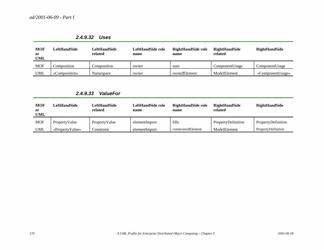
ad/2001-06-09 - Part I
170 A UML Profile for Enterprise Distributed Object Computing – Chapter 3 2001-06-18
2.4.9.32 Uses
MOF or UML
LeftHandSide LeftHandSide related
LeftHandSide role name
RightHandSide role name
RightHandSide related
RightHandSide
MOF Composition Composition owner uses ComponentUsage ComponentUsage
UML «Composition» Namespace owner ownedElement ModelElement «ComponentUsage»
2.4.9.33 ValueFor
MOF or UML
LeftHandSide LeftHandSide related
LeftHandSide role name
RightHandSide role name
RightHandSide related
RightHandSide
MOF PropertyValue PropertyValue elementImport fills PropertyDefinition PropertyDefinition
UML «PropertyValue» Constraint elementImport constrainedElement ModelElement PropertyDefinition
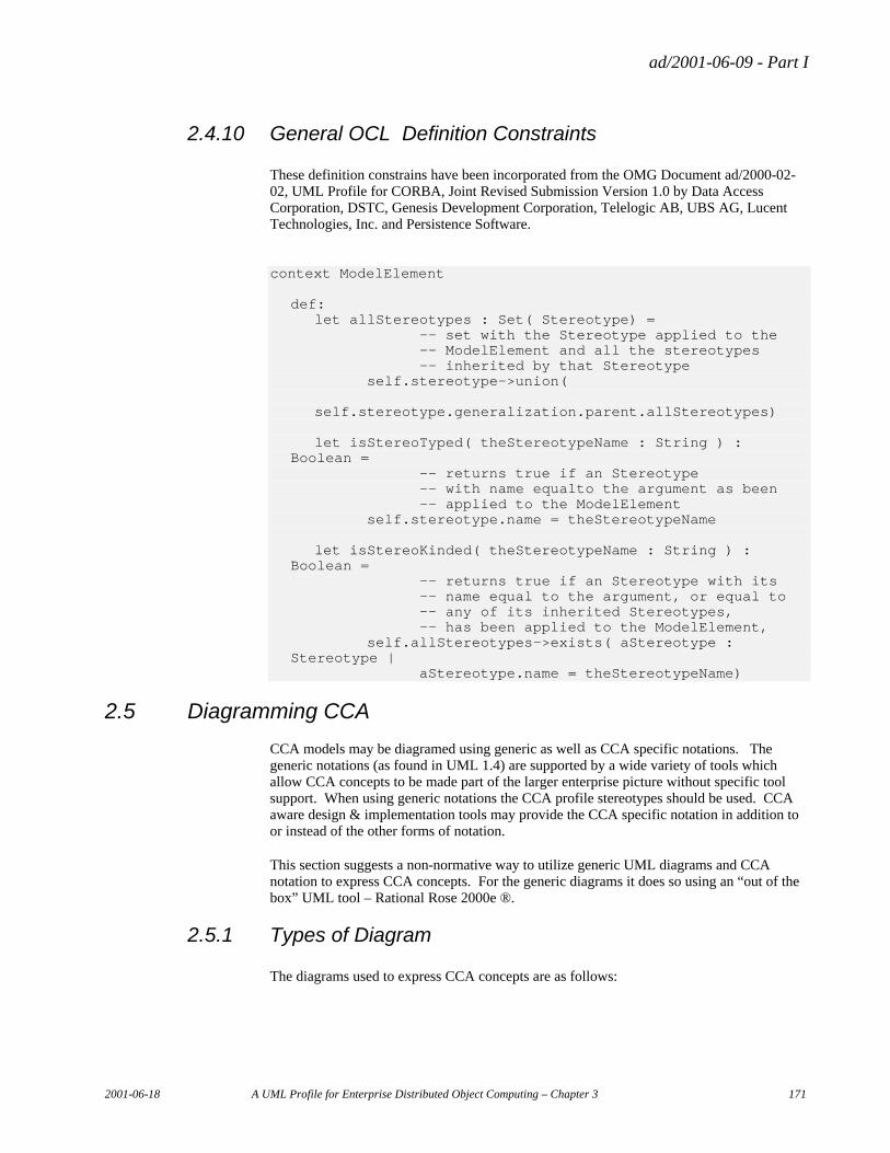
ad/2001-06-09 - Part I
2001-06-18 A UML Profile for Enterprise Distributed Object Computing – Chapter 3 171
2.4.10 General OCL Definition Constraints
These definition constrains have been incorporated from the OMG Document ad/2000-02-02, UML Profile for CORBA, Joint Revised Submission Version 1.0 by Data Access Corporation, DSTC, Genesis Development Corporation, Telelogic AB, UBS AG, Lucent Technologies, Inc. and Persistence Software.
context ModelElement def: let allStereotypes : Set( Stereotype) = -- set with the Stereotype applied to the -- ModelElement and all the stereotypes -- inherited by that Stereotype self.stereotype->union(
self.stereotype.generalization.parent.allStereotypes) let isStereoTyped( theStereotypeName : String ) :
Boolean = -- returns true if an Stereotype -- with name equalto the argument as been -- applied to the ModelElement self.stereotype.name = theStereotypeName let isStereoKinded( theStereotypeName : String ) :
Boolean = -- returns true if an Stereotype with its -- name equal to the argument, or equal to -- any of its inherited Stereotypes, -- has been applied to the ModelElement, self.allStereotypes->exists( aStereotype :
Stereotype | aStereotype.name = theStereotypeName)
2.5 Diagramming CCA
CCA models may be diagramed using generic as well as CCA specific notations. The generic notations (as found in UML 1.4) are supported by a wide variety of tools which allow CCA concepts to be made part of the larger enterprise picture without specific tool support. When using generic notations the CCA profile stereotypes should be used. CCA aware design & implementation tools may provide the CCA specific notation in addition to or instead of the other forms of notation.
This section suggests a non-normative way to utilize generic UML diagrams and CCA notation to express CCA concepts. For the generic diagrams it does so using an “out of the box” UML tool – Rational Rose 2000e ®.
2.5.1 Types of Diagram
The diagrams used to express CCA concepts are as follows:
ad/2001-06-09 - Part I
172 A UML Profile for Enterprise Distributed Object Computing – Chapter 3 2001-06-18
2.5.1.1 Class Diagrams for the Document Model
These are used to express the document model.
2.5.1.2 Class Diagrams for the Component Structure
These are used to define components & protocols, their ports and properties.
2.5.1.3 Collaboration Diagrams for Composition
These are used to express the composition of components within another component or community processes.
2.5.1.4 State or Activity Diagrams for Protocols & Process Components
These express the ordering constraints on ports within or between components.
2.5.1.5 CCA Notation for Process Component Structure & Composition
This expresses the component structure and composition in a more compact and intuitive form, thus replacing the class and collaboration diagrams. We will show how the CCA notation expresses the same concepts found in the generic diagrams.
2.5.2 The Buy/Sell Example
The techniques for diagramming CCA will be presented by example. We will utilize a simple buy/sell business process to illustrate the concepts. We will summarize the points in the specification from the perspective of using a diagramming tool.
The basic business problem of buy/sell is to define a “community process” with two actors – a buyer and seller. These two actors “collaborate” within this process to effect an order.
2.5.3 Collaboration diagram shows community process
At the highest level we show a collaboration diagram of the Buy/Sell community process. In the design tool we also created a package for this process to hold the relevant model elements. See Figure 24.
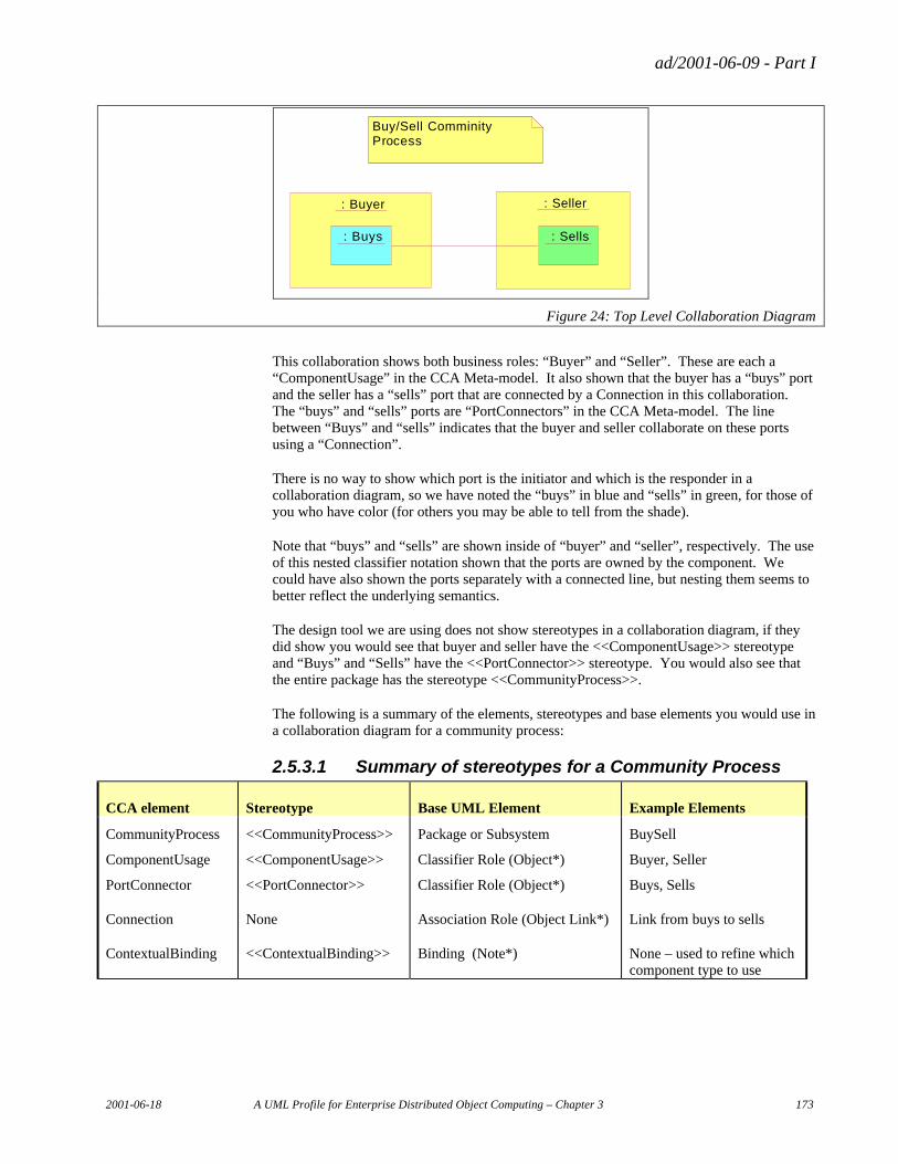
ad/2001-06-09 - Part I
2001-06-18 A UML Profile for Enterprise Distributed Object Computing – Chapter 3 173
: Buyer : Seller
: Buys : Sells
Buy/Sell Comminity Process
Figure 24: Top Level Collaboration Diagram
This collaboration shows both business roles: “Buyer” and “Seller”. These are each a “ComponentUsage” in the CCA Meta-model. It also shown that the buyer has a “buys” port and the seller has a “sells” port that are connected by a Connection in this collaboration. The “buys” and “sells” ports are “PortConnectors” in the CCA Meta-model. The line between “Buys” and “sells” indicates that the buyer and seller collaborate on these ports using a “Connection”.
There is no way to show which port is the initiator and which is the responder in a collaboration diagram, so we have noted the “buys” in blue and “sells” in green, for those of you who have color (for others you may be able to tell from the shade).
Note that “buys” and “sells” are shown inside of “buyer” and “seller”, respectively. The use of this nested classifier notation shown that the ports are owned by the component. We could have also shown the ports separately with a connected line, but nesting them seems to better reflect the underlying semantics.
The design tool we are using does not show stereotypes in a collaboration diagram, if they did show you would see that buyer and seller have the <<ComponentUsage>> stereotype and “Buys” and “Sells” have the <<PortConnector>> stereotype. You would also see that the entire package has the stereotype <<CommunityProcess>>.
The following is a summary of the elements, stereotypes and base elements you would use in a collaboration diagram for a community process:
2.5.3.1 Summary of stereotypes for a Community Process
CCA element Stereotype Base UML Element Example Elements
CommunityProcess <<CommunityProcess>> Package or Subsystem BuySell
ComponentUsage <<ComponentUsage>> Classifier Role (Object*) Buyer, Seller
PortConnector <<PortConnector>> Classifier Role (Object*) Buys, Sells
Connection None Association Role (Object Link*) Link from buys to sells
ContextualBinding <<ContextualBinding>> Binding (Note*) None – used to refine which component type to use
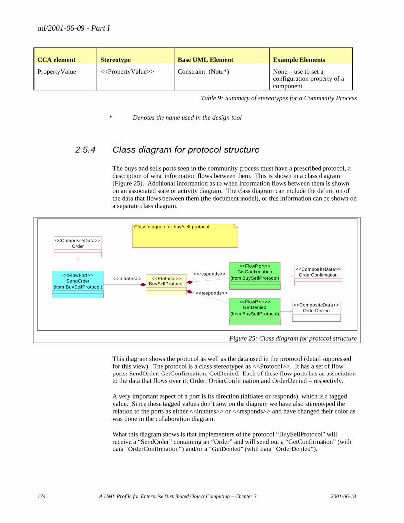
ad/2001-06-09 - Part I
174 A UML Profile for Enterprise Distributed Object Computing – Chapter 3 2001-06-18
CCA element Stereotype Base UML Element Example Elements
PropertyValue <<PropertyValue>> Constraint (Note*) None – use to set a configuration property of a component
Table 9: Summary of stereotypes for a Community Process
* Denotes the name used in the design tool
2.5.4 Class diagram for protocol structure
The buys and sells ports seen in the community process must have a prescribed protocol, a description of what information flows between them. This is shown in a class diagram (Figure 25). Additional information as to when information flows between them is shown on an associated state or activity diagram. The class diagram can include the definition of the data that flows between them (the document model), or this information can be shown on a separate class diagram.
Order<<CompositeData>>
SendOrder(from BuySellProtocol)
<<FlowPort>> OrderConfirmation<<Compos iteData>>GetConfirmat ion
(from BuySellProtocol)
<<FlowP ort>>
BuySellProtocol<<Protocol>><<initiates>>
<<responds>>
OrderDenied<<CompositeData>>GetDenied
(from BuySellProtocol)
<<FlowP ort>>
<<responds>>
Class diagram for buy/sell protocol
Figure 25: Class diagram for protocol structure
This diagram shows the protocol as well as the data used in the protocol (detail suppressed for this view). The protocol is a class stereotyped as <<Protocol>>. It has a set of flow ports: SendOrder, GetConfirmation, GetDenied. Each of these flow ports has an association to the data that flows over it; Order, OrderConfirmation and OrderDenied – respectivly.
A very important aspect of a port is its direction (initiates or responds), which is a tagged value. Since these tagged values don’t sow on the diagram we have also stereotyped the relation to the ports as either <<initates>> or <<responds>> and have changed their color as was done in the collaboration diagram.
What this diagram shows is that implementers of the protocol “BuySellProtocol” will receive a “SendOrder” containing an “Order” and will send out a “GetConfirmation” (with data “OrderConfirmation”) and/or a “GetDenied” (with data “OrderDenied”).
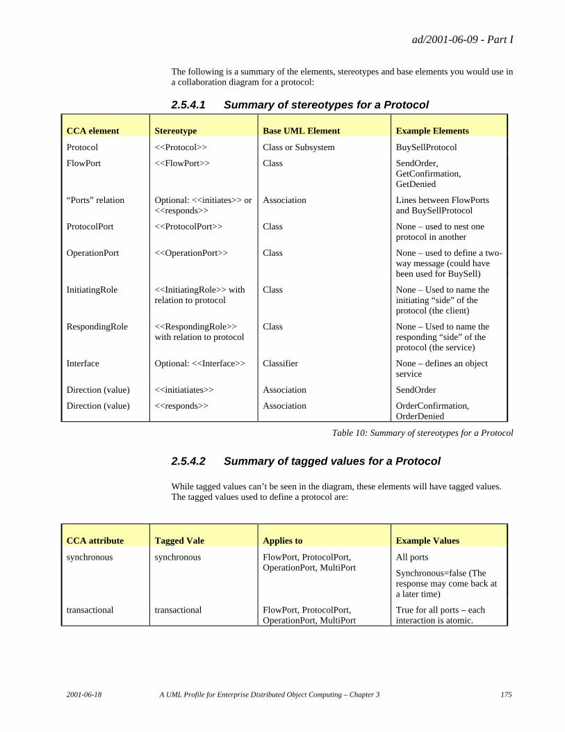
ad/2001-06-09 - Part I
2001-06-18 A UML Profile for Enterprise Distributed Object Computing – Chapter 3 175
The following is a summary of the elements, stereotypes and base elements you would use in a collaboration diagram for a protocol:
2.5.4.1 Summary of stereotypes for a Protocol
CCA element Stereotype Base UML Element Example Elements
Protocol <<Protocol>> Class or Subsystem BuySellProtocol
FlowPort <<FlowPort>> Class SendOrder, GetConfirmation, GetDenied
“Ports” relation Optional: <<initiates>> or <<responds>>
Association Lines between FlowPorts and BuySellProtocol
ProtocolPort <<ProtocolPort>> Class None – used to nest one protocol in another
OperationPort <<OperationPort>> Class None – used to define a two-way message (could have been used for BuySell)
InitiatingRole <<InitiatingRole>> with relation to protocol
Class None – Used to name the initiating “side” of the protocol (the client)
RespondingRole <<RespondingRole>> with relation to protocol
Class None – Used to name the responding “side” of the protocol (the service)
Interface Optional: <<Interface>> Classifier None – defines an object service
Direction (value) <<initiatiates>> Association SendOrder
Direction (value) <<responds>> Association OrderConfirmation, OrderDenied
Table 10: Summary of stereotypes for a Protocol
2.5.4.2 Summary of tagged values for a Protocol
While tagged values can’t be seen in the diagram, these elements will have tagged values. The tagged values used to define a protocol are:
CCA attribute Tagged Vale Applies to Example Values
synchronous synchronous FlowPort, ProtocolPort, OperationPort, MultiPort
All ports
Synchronous=false (The response may come back at a later time)
transactional transactional FlowPort, ProtocolPort, OperationPort, MultiPort
True for all ports – each interaction is atomic.
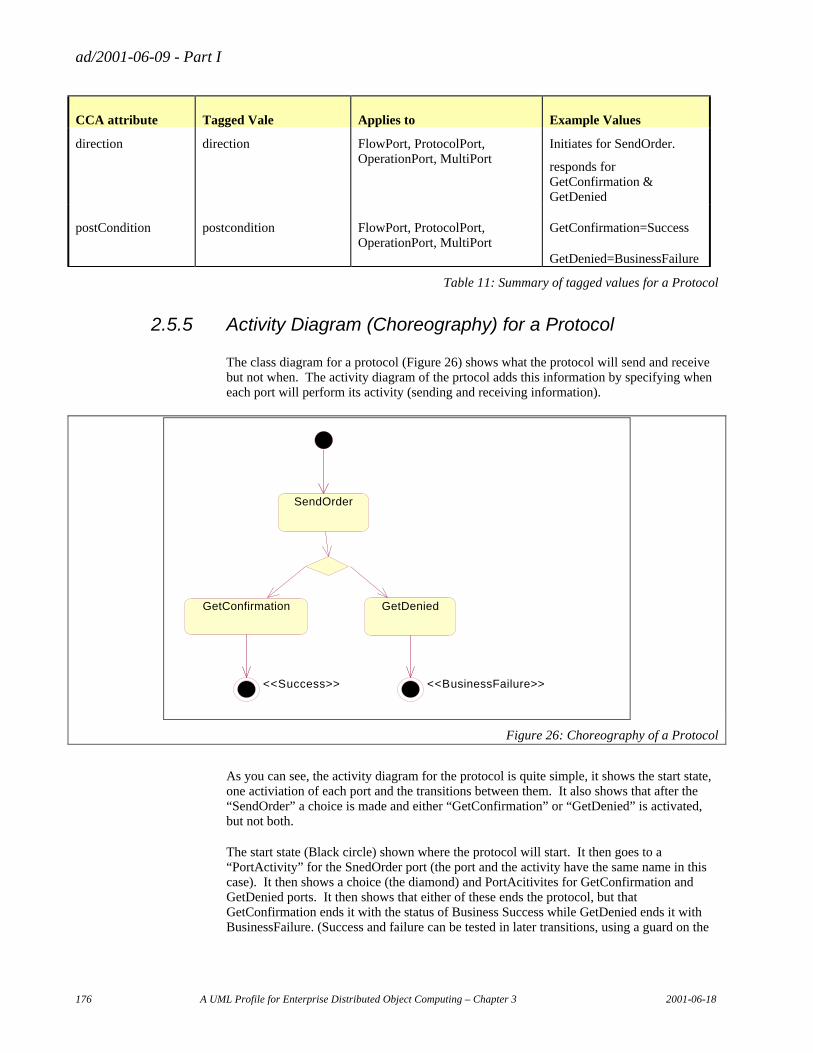
ad/2001-06-09 - Part I
176 A UML Profile for Enterprise Distributed Object Computing – Chapter 3 2001-06-18
CCA attribute Tagged Vale Applies to Example Values
direction direction FlowPort, ProtocolPort, OperationPort, MultiPort
Initiates for SendOrder.
responds for GetConfirmation & GetDenied
postCondition postcondition FlowPort, ProtocolPort, OperationPort, MultiPort
GetConfirmation=Success
GetDenied=BusinessFailure
Table 11: Summary of tagged values for a Protocol
2.5.5 Activity Diagram (Choreography) for a Protocol
The class diagram for a protocol (Figure 26) shows what the protocol will send and receive but not when. The activity diagram of the prtocol adds this information by specifying when each port will perform its activity (sending and receiving information).
SendOrder
GetConfirmation GetDenied
<<Success>> <<BusinessFailure>>
Figure 26: Choreography of a Protocol
As you can see, the activity diagram for the protocol is quite simple, it shows the start state, one activiation of each port and the transitions between them. It also shows that after the “SendOrder” a choice is made and either “GetConfirmation” or “GetDenied” is activated, but not both.
The start state (Black circle) shown where the protocol will start. It then goes to a “PortActivity” for the SnedOrder port (the port and the activity have the same name in this case). It then shows a choice (the diamond) and PortAcitivites for GetConfirmation and GetDenied ports. It then shows that either of these ends the protocol, but that GetConfirmation ends it with the status of Business Success while GetDenied ends it with BusinessFailure. (Success and failure can be tested in later transitions, using a guard on the
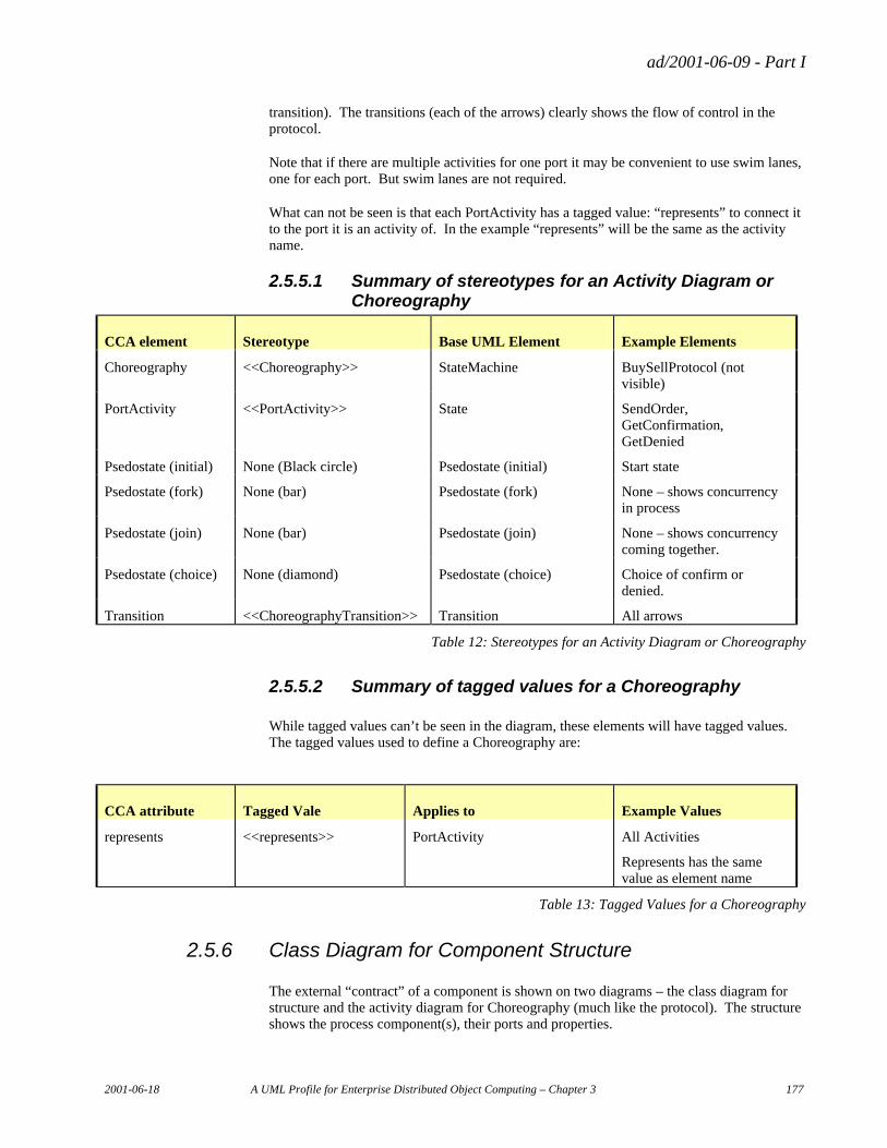
ad/2001-06-09 - Part I
2001-06-18 A UML Profile for Enterprise Distributed Object Computing – Chapter 3 177
transition). The transitions (each of the arrows) clearly shows the flow of control in the protocol.
Note that if there are multiple activities for one port it may be convenient to use swim lanes, one for each port. But swim lanes are not required.
What can not be seen is that each PortActivity has a tagged value: “represents” to connect it to the port it is an activity of. In the example “represents” will be the same as the activity name.
2.5.5.1 Summary of stereotypes for an Activity Diagram or Choreography
CCA element Stereotype Base UML Element Example Elements
Choreography <<Choreography>> StateMachine BuySellProtocol (not visible)
PortActivity <<PortActivity>> State SendOrder, GetConfirmation, GetDenied
Psedostate (initial) None (Black circle) Psedostate (initial) Start state
Psedostate (fork) None (bar) Psedostate (fork) None – shows concurrency in process
Psedostate (join) None (bar) Psedostate (join) None – shows concurrency coming together.
Psedostate (choice) None (diamond) Psedostate (choice) Choice of confirm or denied.
Transition <<ChoreographyTransition>> Transition All arrows
Table 12: Stereotypes for an Activity Diagram or Choreography
2.5.5.2 Summary of tagged values for a Choreography
While tagged values can’t be seen in the diagram, these elements will have tagged values. The tagged values used to define a Choreography are:
CCA attribute Tagged Vale Applies to Example Values
represents <<represents>> PortActivity All Activities
Represents has the same value as element name
Table 13: Tagged Values for a Choreography
2.5.6 Class Diagram for Component Structure
The external “contract” of a component is shown on two diagrams – the class diagram for structure and the activity diagram for Choreography (much like the protocol). The structure shows the process component(s), their ports and properties.
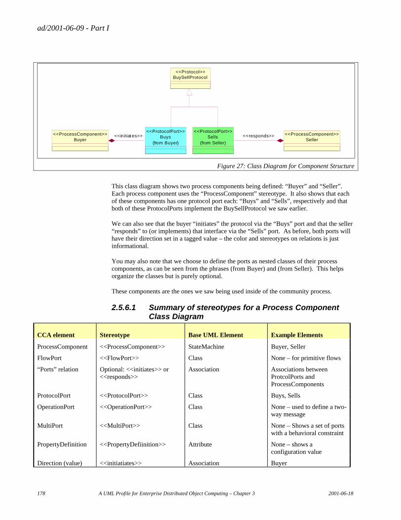
ad/2001-06-09 - Part I
178 A UML Profile for Enterprise Distributed Object Computing – Chapter 3 2001-06-18
Buys(from Buyer)
<<ProtocolPort>>
Buyer<<ProcessComponent>> <<in itiat es>> Sells
(from Seller)
<<ProtocolPort>>
Seller<<ProcessComponent>><<responds>>
BuySellProtocol<<Protocol>>
Figure 27: Class Diagram for Component Structure
This class diagram shows two process components being defined: “Buyer” and “Seller”. Each process component uses the “ProcessComponent” stereotype. It also shows that each of these components has one protocol port each: “Buys” and “Sells”, respectively and that both of these ProtocolPorts implement the BuySellProtocol we saw earlier.
We can also see that the buyer “initiates” the protocol via the “Buys” port and that the seller “responds” to (or implements) that interface via the “Sells” port. As before, both ports will have their direction set in a tagged value – the color and stereotypes on relations is just informational.
You may also note that we choose to define the ports as nested classes of their process components, as can be seen from the phrases (from Buyer) and (from Seller). This helps organize the classes but is purely optional.
These components are the ones we saw being used inside of the community process.
2.5.6.1 Summary of stereotypes for a Process Component Class Diagram
CCA element Stereotype Base UML Element Example Elements
ProcessComponent <<ProcessComponent>> StateMachine Buyer, Seller
FlowPort <<FlowPort>> Class None – for primitive flows
“Ports” relation Optional: <<initiates>> or <<responds>>
Association Associations between ProtcolPorts and ProcessComponents
ProtocolPort <<ProtocolPort>> Class Buys, Sells
OperationPort <<OperationPort>> Class None – used to define a two-way message
MultiPort <<MultiPort>> Class None – Shows a set of ports with a behavioral constraint
PropertyDefinition <<PropertyDefiinition>> Attribute None – shows a configuration value
Direction (value) <<initiatiates>> Association Buyer
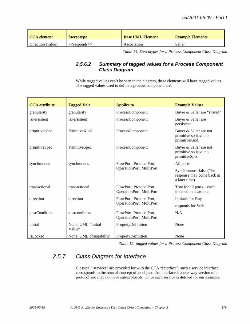
ad/2001-06-09 - Part I
2001-06-18 A UML Profile for Enterprise Distributed Object Computing – Chapter 3 179
CCA element Stereotype Base UML Element Example Elements
Direction (value) <<responds>> Association Seller
Table 14: Stereotypes for a Process Component Class Diagram
2.5.6.2 Summary of tagged values for a Process Component Class Diagram
While tagged values can’t be seen in the diagram, these elements will have tagged values. The tagged values used to define a process component are:
CCA attribute Tagged Vale Applies to Example Values
granularity granularity ProcessComponent Buyer & Seller are “shared”
isPersistent isPersistent ProcessComponent Buyer & Seller are persistent
primitiveKind PrimitiveKind ProcessComponent Buyer & Seller are not primitive so have no primitiveKind.
primitiveSpec PrimitiveSpec ProcessComponent Buyer & Seller are not primitive so have no primitiveSpec
synchronous synchronous FlowPort, ProtocolPort, OperationPort, MultiPort
All ports
Synchronous=false (The response may come back at a later time)
transactional transactional FlowPort, ProtocolPort, OperationPort, MultiPort
True for all ports – each interaction is atomic.
direction direction FlowPort, ProtocolPort, OperationPort, MultiPort
Initiates for Buys
responds for Sells
postCondition postcondition FlowPort, ProtocolPort, OperationPort, MultiPort
N/A
initial None: UML “Initial Value”
PropertyDefinition None
isLocked None: UML changability PropertyDefinition None
Table 15: tagged values for a Process Component Class Diagram
2.5.7 Class Diagram for Interface
Classical “services” are provided for with the CCA “Interface”, such a service interface corresponds to the normal concept of an object. An interface is a one-way version of a protocol and may not have sub-protocols. Once such service is defined for our example.
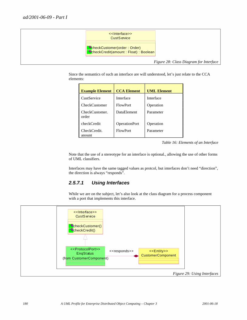
ad/2001-06-09 - Part I
180 A UML Profile for Enterprise Distributed Object Computing – Chapter 3 2001-06-18
CustS ervice
checkCustomer(order : Order)checkCredit(amount : Float) : Boolean
<<Interface>>
Figure 28: Class Diagram for Interface
Since the semantics of such an interface are will understood, let’s just relate to the CCA elements:
Example Element CCA Element UML Element
CustService Interface Interface
CheckCustomer FlowPort Operation
CheckCustomer. order
DataElement Parameter
checkCredit OperationPort Operation
CheckCredit. anount
FlowPort Parameter
Table 16: Elements of an Interface
Note that the use of a stereotype for an interface is optional., allowing the use of other forms of UML classifiers.
Interfaces may have the same tagged values as protcol, but interfaces don’t need “direction”, the direction is always “responds”.
2.5.7.1 Using Interfaces
While we are on the subject, let’s also look at the class diagram for a process component with a port that implements this interface.
CustS ervice
checkCustomer()checkCredit()
<<Interface>>
EnqStatus
(from CustomerComponent)
<<ProtocolPort>>
CustomerComponent<<Entity>><<responds>>
Figure 29: Using Interfaces
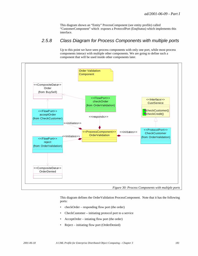
ad/2001-06-09 - Part I
2001-06-18 A UML Profile for Enterprise Distributed Object Computing – Chapter 3 181
This diagram shown an “Entity” ProcessComponent (see entity profile) called “CustomerComponent” which exposes a ProtocolPort (EnqStatus) which implements this interface.
2.5.8 Class Diagram for Process Components with multiple ports
Up to this point we have seen process components with only one port, while most process components interact with multiple other components. We are going to define such a component that will be used inside other components later.
CustService
checkCustomer()checkCredit()
<<Interface>>
CheckCustomer
(from OrderValidation)
<<ProtocolPort>>
checkOrder
(from OrderValidation)
<<FlowPort>>
acceptOrder(from CheckCustomer)
<<FlowP ort>>
Order
(from BuySell)
<<CompositeData>>
OrderValidation<<ProcessComponent>>
OrderDenied<<CompositeData>>
reject
(from OrderValidation)
<<FlowP ort>>
<<ini tiates>>
<<responds>>
<<initiates>>
<<initiates>>
Order Validation Component
Figure 30: Process Components with multiple ports
This diagram defines the OrderValidation ProcessComponent. Note that it has the following ports:
• checkOrder – responding flow port (the order)
• CheckCustomer – initiating protocol port to a service
• AcceptOrder – intiating flow port (the order)
• Reject – initiating flow port (OrderDenied)
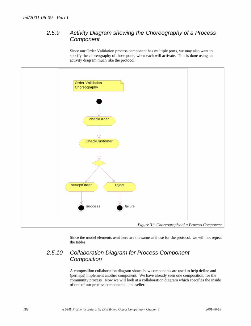
ad/2001-06-09 - Part I
182 A UML Profile for Enterprise Distributed Object Computing – Chapter 3 2001-06-18
2.5.9 Activity Diagram showing the Choreography of a Process Component
Since our Order Validation process component has multiple ports, we may also want to specify the choreography of those ports, when each will activate. This is done using an activity diagram much like the protocol.
checkOrder
rejectacc eptOrder
CheckCustomer
success failure
Order Validation Choreography
Figure 31: Choreography of a Process Component
Since the model elements used here are the same as those for the protocol, we will not repeat the tables.
2.5.10 Collaboration Diagram for Process Component Composition
A composition collaboration diagram shows how components are used to help define and (perhaps) implement another component. We have already seen one composition, for the community process. Now we will look at a collaboration diagram which specifies the inside of one of our process components – the seller.
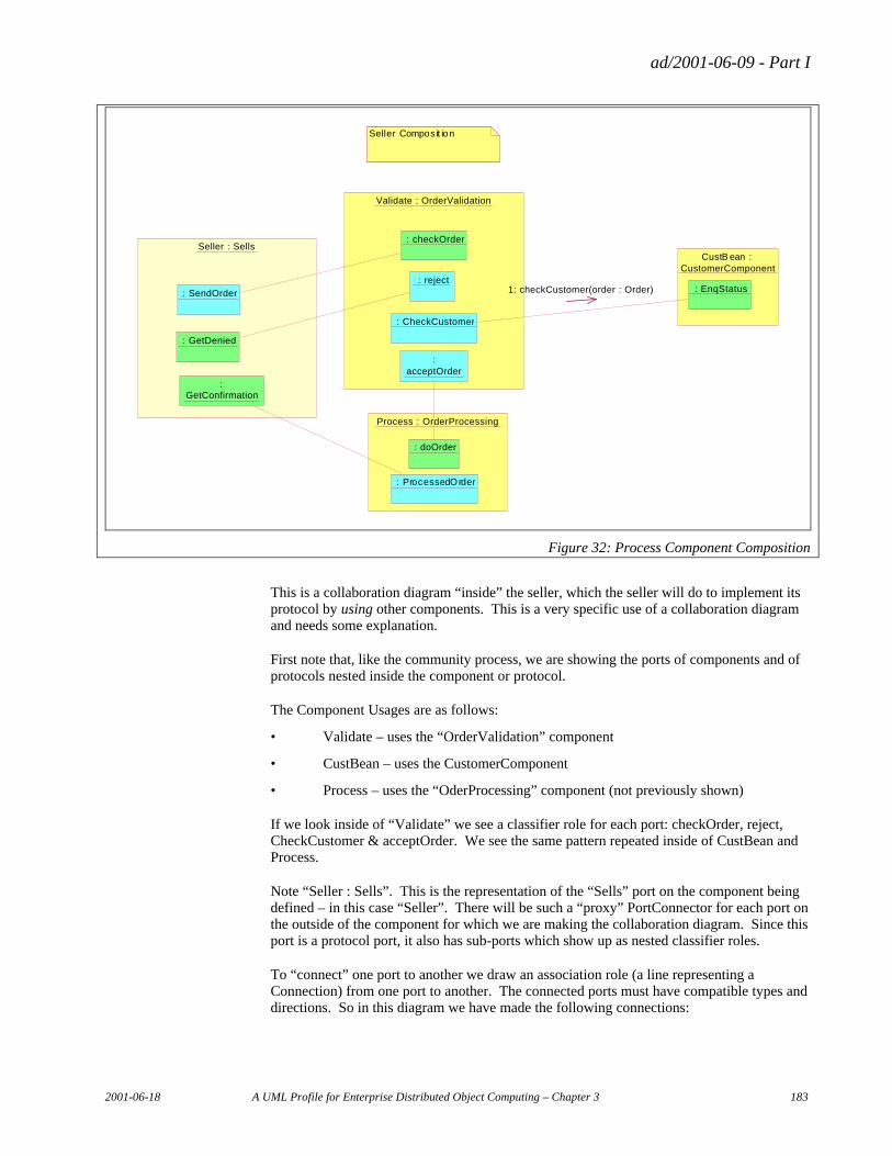
ad/2001-06-09 - Part I
2001-06-18 A UML Profile for Enterprise Distributed Object Computing – Chapter 3 183
Seller : Sells
Validate : OrderValidation
: checkOrder
: reject
: acceptOrder
: CheckCustomer
Process : OrderProcessing
: doOrder
: ProcessedOrder
CustB ean : CustomerComponent
: SendOrder
: GetDenied
: GetConfirmation
: EnqStatus
Seller Composit ion
1: checkCustomer(order : Order)
Figure 32: Process Component Composition
This is a collaboration diagram “inside” the seller, which the seller will do to implement its protocol by using other components. This is a very specific use of a collaboration diagram and needs some explanation.
First note that, like the community process, we are showing the ports of components and of protocols nested inside the component or protocol.
The Component Usages are as follows:
• Validate – uses the “OrderValidation” component
• CustBean – uses the CustomerComponent
• Process – uses the “OderProcessing” component (not previously shown)
If we look inside of “Validate” we see a classifier role for each port: checkOrder, reject, CheckCustomer & acceptOrder. We see the same pattern repeated inside of CustBean and Process.
Note “Seller : Sells”. This is the representation of the “Sells” port on the component being defined – in this case “Seller”. There will be such a “proxy” PortConnector for each port on the outside of the component for which we are making the collaboration diagram. Since this port is a protocol port, it also has sub-ports which show up as nested classifier roles.
To “connect” one port to another we draw an association role (a line representing a Connection) from one port to another. The connected ports must have compatible types and directions. So in this diagram we have made the following connections:
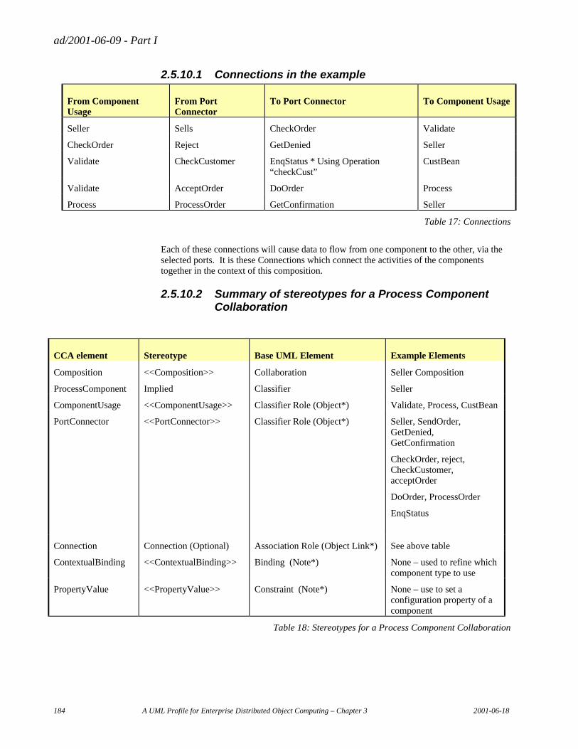
ad/2001-06-09 - Part I
184 A UML Profile for Enterprise Distributed Object Computing – Chapter 3 2001-06-18
2.5.10.1 Connections in the example
From Component Usage
From Port Connector
To Port Connector To Component Usage
Seller Sells CheckOrder Validate
CheckOrder Reject GetDenied Seller
Validate CheckCustomer EnqStatus * Using Operation “checkCust”
CustBean
Validate AcceptOrder DoOrder Process
Process ProcessOrder GetConfirmation Seller
Table 17: Connections
Each of these connections will cause data to flow from one component to the other, via the selected ports. It is these Connections which connect the activities of the components together in the context of this composition.
2.5.10.2 Summary of stereotypes for a Process Component Collaboration
CCA element Stereotype Base UML Element Example Elements
Composition <<Composition>> Collaboration Seller Composition
ProcessComponent Implied Classifier Seller
ComponentUsage <<ComponentUsage>> Classifier Role (Object*) Validate, Process, CustBean
PortConnector <<PortConnector>> Classifier Role (Object*) Seller, SendOrder, GetDenied, GetConfirmation
CheckOrder, reject, CheckCustomer, acceptOrder
DoOrder, ProcessOrder
EnqStatus
Connection Connection (Optional) Association Role (Object Link*) See above table
ContextualBinding <<ContextualBinding>> Binding (Note*) None – used to refine which component type to use
PropertyValue <<PropertyValue>> Constraint (Note*) None – use to set a configuration property of a component
Table 18: Stereotypes for a Process Component Collaboration
ad/2001-06-09 - Part I
2001-06-18 A UML Profile for Enterprise Distributed Object Computing – Chapter 3 185
2.5.10.3 Special note on “proxy” port activities.
As can be seen from the example, we need to connect the “outside” ports (those on the component being defined) with the “inside” ports (those on the components being used). The PortConnectors for the outside ports are shown without an owning ComponentUsage, while the PortConnectors for the components being used are shown inside of the ComponentUsage being used.
2.5.10.4 Special note on protocols
Since protocols give us the ability to “nest” ports, ports may be seen within ports to any level. This example only shown one level of such nesting. The same kind of nesting is used within activity diagrams – since activities may be nested as well.
2.5.11 Model Management
While the organizational structure of components is not visible in a diagram, it is visible in tools. The screen shot in Figure 33 shows how the example components are organized in the Data Access Technologies’ UML tool. Note how using nested classes (such as Ports being inside of their ProcessComponent) helps to organize the model and keep namespaces separate.
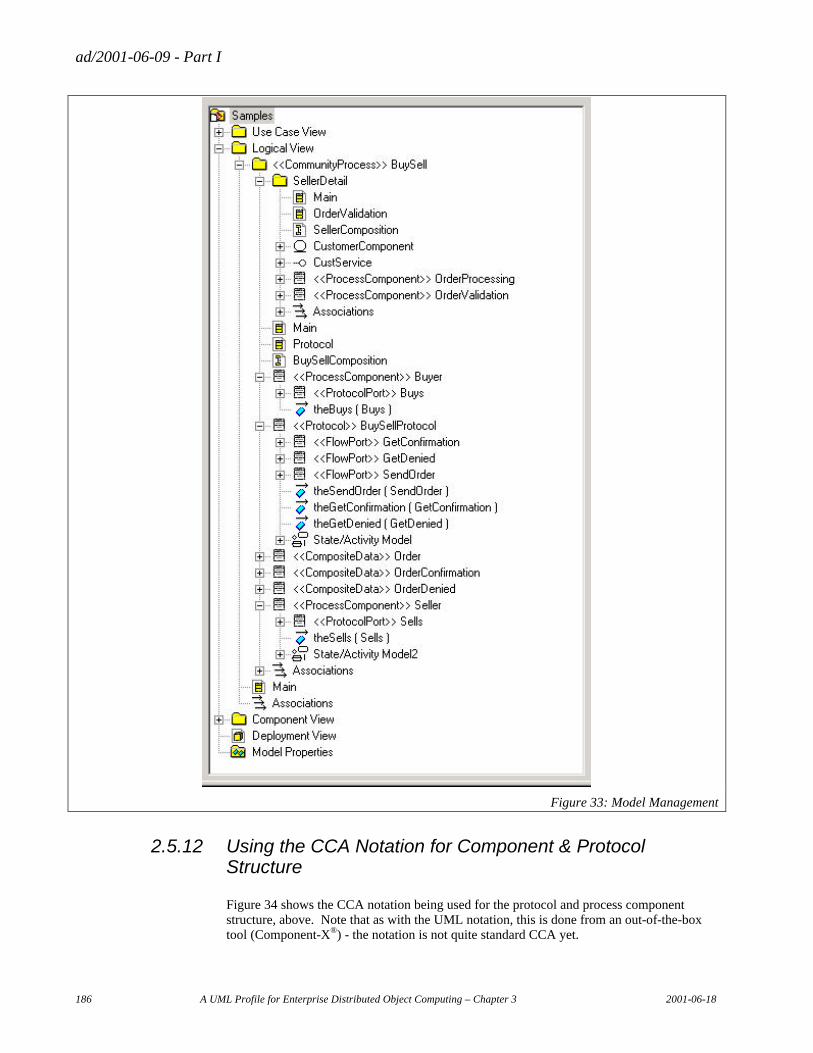
ad/2001-06-09 - Part I
186 A UML Profile for Enterprise Distributed Object Computing – Chapter 3 2001-06-18
Figure 33: Model Management
2.5.12 Using the CCA Notation for Component & Protocol Structure
Figure 34 shows the CCA notation being used for the protocol and process component structure, above. Note that as with the UML notation, this is done from an out-of-the-box tool (Component-X®) - the notation is not quite standard CCA yet.
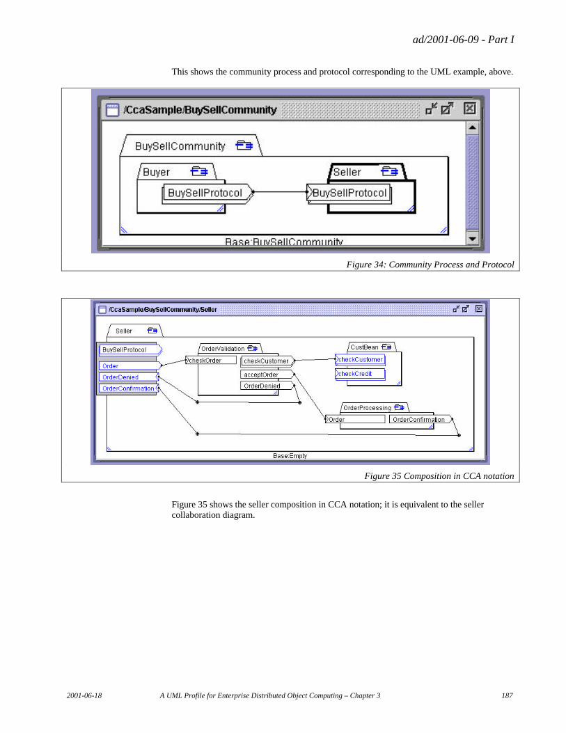
ad/2001-06-09 - Part I
2001-06-18 A UML Profile for Enterprise Distributed Object Computing – Chapter 3 187
This shows the community process and protocol corresponding to the UML example, above.
Figure 34: Community Process and Protocol
Figure 35 Composition in CCA notation
Figure 35 shows the seller composition in CCA notation; it is equivalent to the seller collaboration diagram.
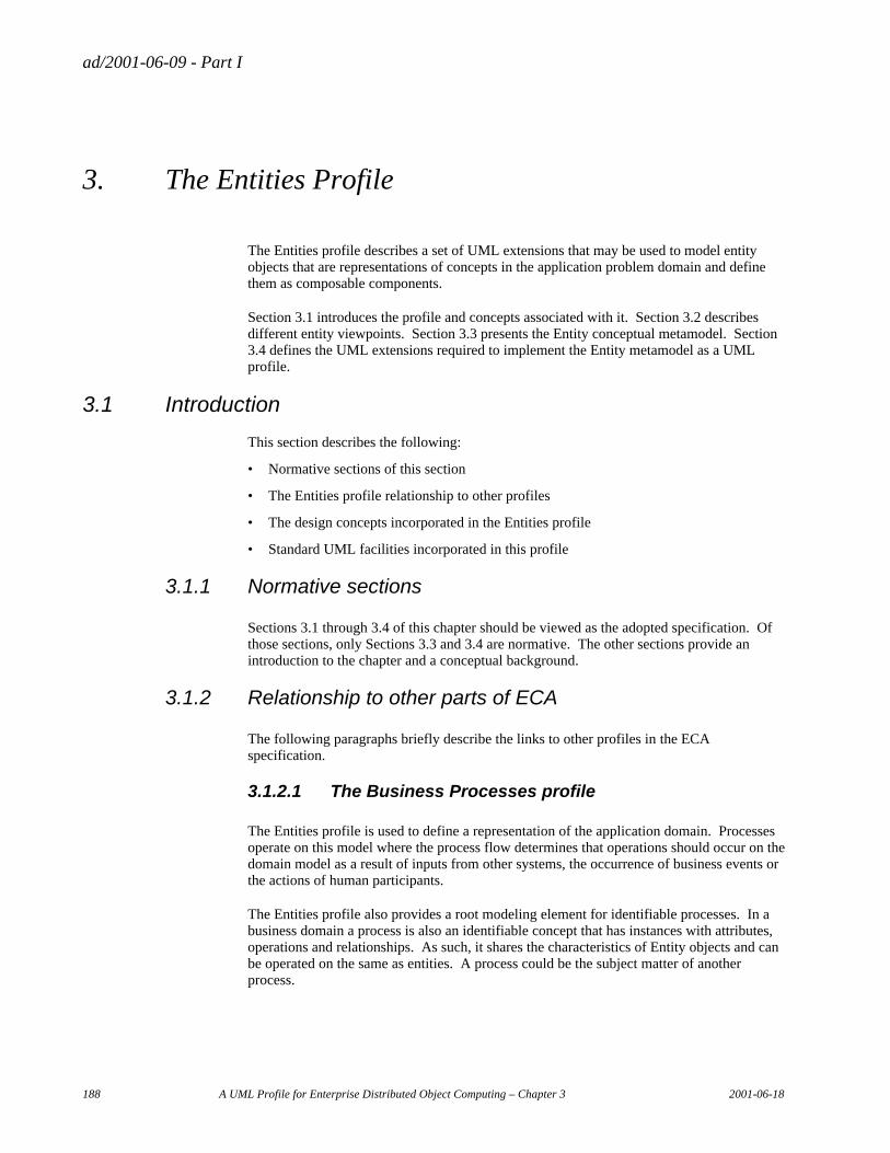
ad/2001-06-09 - Part I
188 A UML Profile for Enterprise Distributed Object Computing – Chapter 3 2001-06-18
3. The Entities Profile
The Entities profile describes a set of UML extensions that may be used to model entity objects that are representations of concepts in the application problem domain and define them as composable components.
Section 3.1 introduces the profile and concepts associated with it. Section 3.2 describes different entity viewpoints. Section 3.3 presents the Entity conceptual metamodel. Section 3.4 defines the UML extensions required to implement the Entity metamodel as a UML profile.
3.1 Introduction
This section describes the following:
• Normative sections of this section
• The Entities profile relationship to other profiles
• The design concepts incorporated in the Entities profile
• Standard UML facilities incorporated in this profile
3.1.1 Normative sections
Sections 3.1 through 3.4 of this chapter should be viewed as the adopted specification. Of those sections, only Sections 3.3 and 3.4 are normative. The other sections provide an introduction to the chapter and a conceptual background.
3.1.2 Relationship to other parts of ECA
The following paragraphs briefly describe the links to other profiles in the ECA specification.
3.1.2.1 The Business Processes profile
The Entities profile is used to define a representation of the application domain. Processes operate on this model where the process flow determines that operations should occur on the domain model as a result of inputs from other systems, the occurrence of business events or the actions of human participants.
The Entities profile also provides a root modeling element for identifiable processes. In a business domain a process is also an identifiable concept that has instances with attributes, operations and relationships. As such, it shares the characteristics of Entity objects and can be operated on the same as entities. A process could be the subject matter of another process.
ad/2001-06-09 - Part I
2001-06-18 A UML Profile for Enterprise Distributed Object Computing – Chapter 3 189
3.1.2.2 The CCA profile
Elements of the Entities profile are also characterized as composed components that can be composed into larger components. As components they may be made available for composition of a variety of systems. As composed components, they may be configured from independently created components. The component profile determines the unit of composition and the interconnection of interfaces that enables the components to work together.
3.1.2.3 The Events profile
The event profile defines the integration of systems and components using events to drive the processing. Events may be published or received by entities and processes. Events may be forwarded synchronously or asynchronously. Synchronous events will typically be delivered within the context of the current transaction. Asynchronous events will generally be stored and delivered in the context of a new transaction. The use of events for integration reduces coupling and improves the ease by which a system may be adapted or extended.
The Entities profile recognizes the publish and subscribe ports as elements that may be attached to entity components. In addition, it defines the Data Probe port to generate events requested on an ad hoc basis.
3.1.2.4 The Relationships profile
Entities have relationships. Relationships represent associations between the real-world counterparts of domain model elements. The variety of relationships is defined by the Relationship Profile.
3.1.2.5 The Patterns profile
Patterns may be used to replicate frequently occurring entity structures including attributes, relationships, operations, rules and constraints.
3.1.3 Design Concepts
The entity model reflects the integration of a number of design concepts:
• Composition
• Encapsulation
• Ports
• Identity
• Events
• Domain Modeling
• Entity Role
• Events
• Data Monitoring
• Distributed Computing
• Levels of Coupling
ad/2001-06-09 - Part I
190 A UML Profile for Enterprise Distributed Object Computing – Chapter 3 2001-06-18
These concepts are each discussed in the paragraphs that follow.
3.1.3.1 Composition
Entities are representations of concepts that exist in the real world or application problem domain. The primary purpose of the entity profile is to model entities–their relationships, attributes and methods—and define them as composable components.
The information viewpoint will provide the primary notation for modeling entities and their attributes and relationships as data. The entities represented in the information viewpoint are then incorporated into objects, described as composable components.
Entities are incorporated into systems where they may be acted upon by processes, interact with other entities and generate events. Thus entities are components in a larger system. The component relationships of entities to other components is expressed in the composition viewpoint. In this viewpoint entities are components that are composed into larger components.
As a component, an entity may have several different ports. It receives and responds to messages. It may send messages and receive return values, it may generate events or asynchronous messages and it may receive events or asynchronous messages. In addition, it may accept ad hoc requests to generate messages based on changes in its state.
Entities that represent primary concepts, such as Customer, will often be composed with related entities and value objects as deployable components. So the Customer and Account entities could be composed into one component also containing the Customer Address and Account Entry value objects.
3.1.3.2 Encapsulation
Entity components are intended to be encapsulations of their associated data and functionality. Process Component defined in the CCA specification provides the basic representation of encapsulation. It provides the external interfaces by which these components are linked to other components and composed into larger components. At the same time, it does not define the component implementation.
Data Manager extends this by incorporating Composite Data. Consequently, a data manager contains composite data that describes the state of the component. Data Manager incorporates the composite data and relationships of Entity Data along with methods to operate on the data.
A Data Manager may be implemented as an object. The object has an interface, modeled as a component port, and it has state data that may be accessed through the port. The object may also have other ports. It may have data probe ports to generate messages based on ad hoc requests. It may send asynchronous messages and events. If it has a unique identity (i.e., is an Entity), and is sharable and network accessible, it can receive asynchronous messages and events.
Data Manager comprehends value objects, objects that are passed by value, i.e., by copying the data, not by reference. Consequently, the data structure is exposed when a copy is performed. It is important to distinguish between the value object that has a functional interface, and the state of the value object, the Entity Data, which is passed when a value object is passed as a parameter.
ad/2001-06-09 - Part I
2001-06-18 A UML Profile for Enterprise Distributed Object Computing – Chapter 3 191
Value objects are not sharable nor network accessible. They cannot receive messages over the network, and they are not sharable because they are always passed by value rather than by reference.
Data Managers may be network accessible or not. A Data Manager may be only accessible by reference to a related entity that is network accessible. For example, a order line item is identifiable but may only be accessible through the order.
An Entity may be a copy of a primary Entity, i.e., a clone, for purposes of improving performance. An Entity clone may be a copy of an entity on a client system that is used for interactive operations. Or the clone could be the instantiation of an entity when concurrency control is performed by a database (i.e., the primary entity is in the database). The clone is instantiated with a copy of the entity’s state. The primary Entity should be locked when the copy is taken so that it’s state will not change while operations are being performed on the clone. The clone is not sharable because it should not exist beyond the transaction in which it was created. Its lock on the primary entity will expire when its transaction terminates.
3.1.3.3 Ports
Components interact with their environment through ports. A port has a defined interaction protocol. Ports may send messages, receive messages, or both. A port may be implemented as an object interface, e.g., CORBA or Java interface.
Ports are synchronous or asynchronous. A synchronous port communicates within the context of a transaction. An asynchronous port communicates in a store-and-forward manner so that sending a message occurs in the context of one transaction and receipt of the message then occurs in the context of another transaction.
Ports may communicate with messages or event notices. A message is directed to a specific destination. An event notice is published to the communication infrastructure to be delivered to subscribers—destinations that have expressed interest. The messages and event notices may be communicated synchronously or asynchronously.
All Data Managers will have a synchronous interface port that represents the typical object interface. A Data Manager may have other ports, such as to send messages to other Data Managers, and to send and receive asynchronous messages and events.
3.1.3.4 Identity
Unique identity is introduced on Entity Data and implicitly on Entity with the addition of a Key. A prime key is required to be unique within the extent of the type. In general, identifiable components are passed by reference.
The key may be comprised of one or more attributes of the state of the component, and these elements must be immutable. The key can also have elements that are Foreign Keys of other Entities. A Foreign Key is identified through a relationship with another Entity from which the Foreign Key is derived.
An Entity component has a primary instance, i.e., the location of the master copy of its state. This master copy may be in a database or it may be instantiated as an object/component. Copies of an Entity state may be instantiated in Entity clones. These are not sharable and, in general, should not exist beyond the scope of a single transaction.
Entity components can be “managed.” This property specifies that the extent of all members of a type and its sub-types is known and may be accessed as a set. The key of an identifiable
ad/2001-06-09 - Part I
192 A UML Profile for Enterprise Distributed Object Computing – Chapter 3 2001-06-18
component must be unique within its managed extent. The implementation implication of being managed is that the type will have an extent manager or “home” that will provide query access to the extent and may provide attributes and methods that apply to all members of the extent or the members collectively, e.g., the number of members.
3.1.3.5 Domain Modeling
The first step in modeling a business domain may be to create and information viewpoint. The information viewpoint exposes the Entity Data along with its attributes and relationships. These Entity Data elements will be incorporated into Entity components to define their functionality and interfaces.
In modeling a business domain, business concepts that are uniquely identifiable must be represented by identifiable computational components. For example, an object representing an employee, a purchase order, an office or a part specification will have a unique identifier that associates the object with the real-world counterpart. As such, a consistent representation of the business will have a single representation of each real-world thing as an identifiable object. While an implementation may replicate such elements for performance or reliability, replicas are still logically a single representation and must be maintained with consistent state if the system is to yield consistent results.
For the most part, the identifiable elements that model the business domain are characterized as Entities. Rules and Processes are also Entities because they have state and are identifiable, but they are computational artifacts that describe activities in which entities are involved.
3.1.3.6 Entity Role
The Entity Role is an important extension to the Entity representation. It may be impractical to design an Entity component to anticipate all circumstances in which an entity may be involved. Each situation may involve different state and behaviour. An Entity Role incorporates aspects of an Entity associated with a particular context. It essentially extends an Entity on an ad hoc basis. The unique identity of an Entity Role is the entity identifier coupled with its context identifier. Consequently, the context must also be represented as an Entity component. For example, a person has the role of an employee as a member of an enterprise (context), or may be a member of a project team. An entity may have many roles as appropriate to the different contexts in which it participates.
An Entity Role is dependent upon the associated parent entity. The association is immutable. If an Entity ceases to exist, all of its roles will also cease to exist. An Entity Role cannot be assigned to another parent Entity.
An Entity Role is not an appropriate representation for such concepts as an organisational position or the specification of a process participant. These concepts may define characteristics of the entities that can be assigned, but should not include characteristics that are unique to a particular Entity when assigned. Consequently, a process participant is an Entity that represents a potential association of a process with an Entity. Different Entities may be assigned to the participation over time. An Entity Role may be assigned to the participation, as an employee may be assigned to participate in a process, and a different employee may be substituted at a later time.
An Entity Role may be a “virtual entity” if it incorporates all of the interface characteristics of the entity it represents. For example, an Entity Role may inherit the interface of its associated Entity, incorporate the interface by inheritance and incorporate the entity state and behaviour by delegation.
ad/2001-06-09 - Part I
2001-06-18 A UML Profile for Enterprise Distributed Object Computing – Chapter 3 193
3.1.3.7 Events
An event represents a change of state in a system that is of interest outside the scope of the component in which it occurs. An event may be defined as a change of state that causes a condition of interest to become true, or an event may be associated with a state transition to a particular state, from a particular state, or from one state to another state. When an event occurs a notice can be generated.
The ability to generate event notices can be designed into a component. The content of the event notice is defined to provide appropriate information about the event. Event notices are published—they are issued to the event communication infrastructure to be received by subscribers. The publisher of an event notice is not expected to be aware of the subscribers, and thus there may be many subscribers or none. Similarly, the subscribers are not aware of the specific sources of event notices to which they subscribe.
The Event Publication and Event Subscription ports provide the complementary interfaces for this publish and subscribe linkage between components. These ports may be defined as operating in synchronous or asynchronous mode.
The mode of a subscriber must match the mode of the receiver for an event notice to be communicated. In synchronous mode, an event notice would be delivered to all subscribers within the context of the transaction in which the event occurred. In asynchronous mode, the event would be delivered in a store-and-forward manner, the event notice would be captured in one transaction and accepted by each subscriber in different transactions.
3.1.3.8 Data Monitoring
Data monitoring refers to the ability to ad hoc initiate detection of changes in data in order to initiate desired actions. This capability is an important element of flexibility and modularity of system design. It allows actions to be initiated based on changes in state without explicitly embedding the initiation of those actions in the executable logic that changes the data.
For example, an application may be designed to monitor the price of a commodity to initiate buy or sell orders or alert a customer. It should not be necessary to modify the logic of the commodity tracking system in order to link this monitoring application to price changes.
Similarly, when a system is assembled or extended using components, actions of some components may be dependent on changes in state in other components. By providing the ability to monitor changes in the data of a component, the logic of the component need not be designed to anticipate each specific dependence.
The Data Probe port provides the interface for accepting and removing monitoring requests and for issuing events or messages when the specified events occur in the state of the Entity. A request will defines the state of interest, the type of message to be sent and the message addressee.
3.1.3.9 Distributed Computing
Components that are remotely accessible must be identifiable. Their unique identity is the basis for locating them in the distributed computing environment. It is also the basis for sharing a single representation of the state of the thing being represented.
To support network access, they must have one or more ports that support network access protocols. For example, a network accessible component might have ports synchronous
ad/2001-06-09 - Part I
194 A UML Profile for Enterprise Distributed Object Computing – Chapter 3 2001-06-18
messaging ports implemented as CORBA interfaces, and event subscription and publication ports implemented as JMS (Java Messsaging Service) subscriber and publisher interfaces.
Data Managers that are not network accessible will be restricted to being co-located with components that reference them. For example, an order item is uniquely identified within an order, but remote access may be only through interfaces to the containing order.
Relationships require that the participating Entity Data structures are identifiable. At the same time, the Data Manager of an Entity Data structure may not be network accessible. In a distributed computing environment, components that participate in relationships must be either co-located or be network accessible. A relationship cannot be implemented if the members cannot communicate with each other.
While distribution of computing is primarily an implementation issue, the ability for components to be distributed must be considered fairly early in the design. Where Entity components are not network accessible, operations on their containing components will likely reflect indirect access from remote components.
3.1.3.10 Levels of Coupling
The Entity Model anticipates three levels of component coupling: linked, tightly coupled and loosely coupled.
Linked coupling refers to components that are co-located in the same address space. These components interact with each other directly, without communicating over a network. As such, they can interact without being network accessible components. Messaging will generally be synchronous, within the scope of a single transaction.
Tightly coupled components are distributed across multiple servers. These components will also interact with synchronous messaging, but messaging will occur over a network. While some messaging between the components may be asynchronous for performance and recoverability considerations, components are tightly coupled if any interactions between them are synchronous.
Loosely coupled components are distributed and only communicate asynchronously, through a messaging infrastructure. Communication is through messages and events. These components might be characterized as enterprise applications. A message or event is issued in the scope of one transaction and accepted by one or more recipients in independent transactions. Messages and events are stored and forwarded. A message is a communicated with a defined recipient, and an event is a communicated (published) with self-declaring recipients (subscribers) unknown to the publisher.
The level of coupling between components has important performance and system flexibility implications. Generally, components should be designed in a level-of-coupling hierarchy so that components that are linked are within components that are tightly coupled, and tightly coupled components are within components that are loosely coupled with each other. This coupling hierarchy should be reflected in the network accessibility property of components and the synchronous vs. asynchronous property of their ports.
3.1.4 Standard UML Facilities
This section briefly describes the standard elements of UML that are incorporated in the profile.
ad/2001-06-09 - Part I
2001-06-18 A UML Profile for Enterprise Distributed Object Computing – Chapter 3 195
Attributes
Composite Data elements define their data elements with attributes. Composite Data elements are incorporated as the data structures of Data Managers, which are specialized to entities. The interfaces to Data Managers provide access to the attributes and will generally have methods by the same name as accessers.
Methods
Methods are specified as in UML. From a component perspective, methods, including the attribute accesser methods, are incorporated in the port(s) which receive messages and return a result.
Relationships
Relationships express associations between non-primitive elements. Identifiable, sharable and network accessible elements can have relationships that extend over a distributed network.
Activity Graphs
Activity Graphs may be used to describe flow of control between elements, although these will be more applicable for describing processes.
State Machines
Changes of state of elements with data may be described with state machines. Publication of events may be defined in terms of state transitions.
Interaction diagrams
Interaction diagrams may be used to describe the flow of control between executable elements.
Object Constraint Language
OCL is used to express conditions for triggers, as well as in other applicable UML elements.
3.2 Entity viewpoints
The entity profile provides elements that appear in different viewpoints. These viewpoints are for different purposes and represent entities differently, using different forms of notation. Two viewpoints of particular interest are presented below: the information viewpoint and the composition viewpoint. Entities also appear in other diagrams, for example, in interaction diagrams as vertical lines and in activity diagrams as swim lanes.
3.2.1 Information viewpoint
The information viewpoint models Entity Data and their relationships. Entities represent concepts in the problem domain, and relationships represent relationships between the
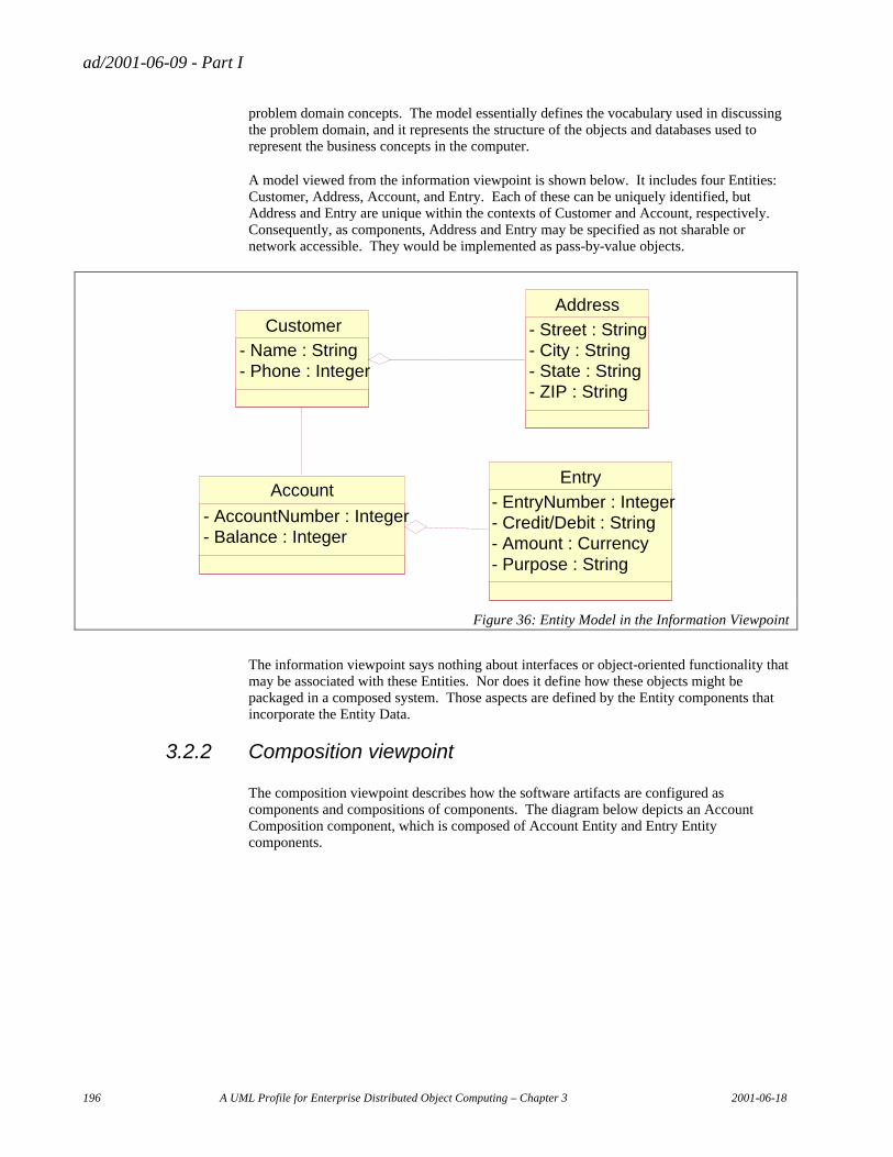
ad/2001-06-09 - Part I
196 A UML Profile for Enterprise Distributed Object Computing – Chapter 3 2001-06-18
problem domain concepts. The model essentially defines the vocabulary used in discussing the problem domain, and it represents the structure of the objects and databases used to represent the business concepts in the computer.
A model viewed from the information viewpoint is shown below. It includes four Entities: Customer, Address, Account, and Entry. Each of these can be uniquely identified, but Address and Entry are unique within the contexts of Customer and Account, respectively. Consequently, as components, Address and Entry may be specified as not sharable or network accessible. They would be implemented as pass-by-value objects.
Address
- Street : String - City : String - State : String - ZIP : String
Customer - Name : String - Phone : Integer
Account
- AccountNumber : Integer - Balance : Integer
Entry - EntryNumber : Integer - Credit/Debit : String - Amount : Currency - Purpose : String
Figure 36: Entity Model in the Information Viewpoint
The information viewpoint says nothing about interfaces or object-oriented functionality that may be associated with these Entities. Nor does it define how these objects might be packaged in a composed system. Those aspects are defined by the Entity components that incorporate the Entity Data.
3.2.2 Composition viewpoint
The composition viewpoint describes how the software artifacts are configured as components and compositions of components. The diagram below depicts an Account Composition component, which is composed of Account Entity and Entry Entity components.
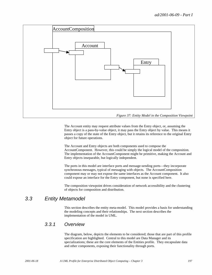
ad/2001-06-09 - Part I
2001-06-18 A UML Profile for Enterprise Distributed Object Computing – Chapter 3 197
Account
Entry
AccountComposition
Account
Entry
AccountComposition
Figure 37: Entity Model in the Composition Viewpoint
The Account entity may request attribute values from the Entry object, or, assuming the Entry object is a pass-by-value object, it may pass the Entry object by value. This means it passes a copy of the state of the Entry object, but it retains its reference to the original Entry object for future operations.
The Account and Entry objects are both components used to compose the AccountComponent. However, this could be simply the logical model of the composition. The implementation of the AccountComponent might be primitive, making the Account and Entry objects inseparable, but logically independent.
The ports in this model are interface ports and message-sending ports—they incorporate synchronous messages, typical of messaging with objects. The AccountComposition component may or may not expose the same interfaces as the Account component. It also could expose an interface for the Entry component, but none is specified here.
The composition viewpoint drives consideration of network accessibility and the clustering of objects for composition and distribution.
3.3 Entity Metamodel
This section describes the entity meta-model. This model provides a basis for understanding the modeling concepts and their relationships. The next section describes the implementation of the model in UML.
3.3.1 Overview
The diagram, below, depicts the elements to be considered; those that are part of this profile specification are highlighted. Central to this model are Data Manager and its specializations; these are the core elements of the Entities profile. They encapsulate data and other components, exposing their functionality through ports.
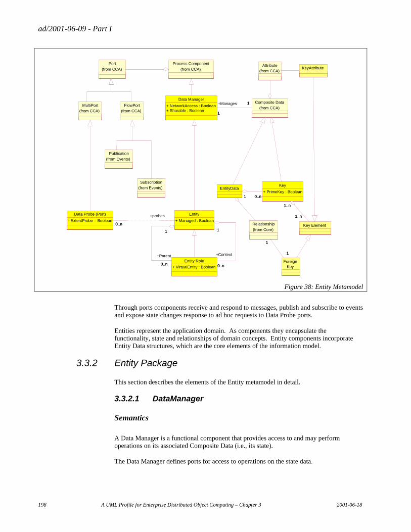
ad/2001-06-09 - Part I
198 A UML Profile for Enterprise Distributed Object Computing – Chapter 3 2001-06-18
Publication (from Events)
Subscription (from Events)
Process Component (from CCA)
Port (from CCA)
Foreign Key
Relationship (from Core)
1 1
1 1
Key Element
EntityData Key + PrimeKey : Boolean
1..n 1..n
1..n 1..n
1 0..n 1 0..n
KeyAttribute
Entity Role + VirtualEntity : Boolean
Entity + Managed : Boolean
1
0..n
1
+Context 0..n 0..n
+Parent 0..n
Data Probe (Port) - ExtentProbe = Boolean
1 0..n
+probes
1 0..n
Attribute (from CCA)
Composite Data (from CCA)
Data Manager + NetworkAccess : Boolean + Sharable : Boolean
1 1
1 1
MultiPort (from CCA)
FlowPort (from CCA)
+Manages
Figure 38: Entity Metamodel
Through ports components receive and respond to messages, publish and subscribe to events and expose state changes response to ad hoc requests to Data Probe ports.
Entities represent the application domain. As components they encapsulate the functionality, state and relationships of domain concepts. Entity components incorporate Entity Data structures, which are the core elements of the information model.
3.3.2 Entity Package
This section describes the elements of the Entity metamodel in detail.
3.3.2.1 DataManager
Semantics
A Data Manager is a functional component that provides access to and may perform operations on its associated Composite Data (i.e., its state).
The Data Manager defines ports for access to operations on the state data.
ad/2001-06-09 - Part I
2001-06-18 A UML Profile for Enterprise Distributed Object Computing – Chapter 3 199
UML base element(s) in the Profile
Class
Fully Scoped name
EDOC::ECA::Entity::Data Manager
Owned by
Package
Properties
Network Access
A Boolean value which indicates if the Data Manager is intended to be accessible over the network.
Sharable
A Boolean value which indicates if the Data Manager can be shared by multiple transactions/sessions. A Data Manager that is not sharable is either transient or depends on a sharable Data Manager that contains it for persistence. For example, an address may not be sharable (although its state may be passed by value), but it can be persistent by association with a Customer that is sharable.
Related elements
Process Component
Data Manager inherits from Process Component and adds the quality of having associated state.
Composite Data
Composite Data defines the data structure that is encapsulated by the Data Manager.
Entity
Entity specializes Data Manager for representation of identifiable application domain things.
ad/2001-06-09 - Part I
200 A UML Profile for Enterprise Distributed Object Computing – Chapter 3 2001-06-18
Constraints
N/A
3.3.2.2 EntityData
Semantics
Entity Data is the data structure that represents a concept in the business domain. It is equivalent to an entity in data modelling or a relation in a relational database. In a Data Manager or its specializations, such as Entity, it represents the state of an object.
Entity Data has attributes (from Data Element) and relationships. The information viewpoint is a viewpoint on Entity Data elements.
UML base element(s) in the Profile
Class
Fully Scoped name
EDOC::ECA::Entity::EntityData
Owned by
Package
Properties
N/A
Related elements
Composite Data
Entity Data inherits from Composite Data and adds relationships.
Relationship
Describes an association between Entity Data elements.
Data Manager
A Entity Data element is incorporated in a Data Manager which gives it functionality and ports as a component.
ad/2001-06-09 - Part I
2001-06-18 A UML Profile for Enterprise Distributed Object Computing – Chapter 3 201
Constraints
• Entity Data must have a prime Key that is unique within the extent of the Entity Data type (i.e., the type and all sub-types).
• Entity Data is managed by an Entity Data Manager.
3.3.2.3 Key
Semantics
A Key is a value that may be used to identify a Data Entity for some purpose. Generally, it will be a unique identifier within some context. A Key designated Prime Key = true is the key intended for unique identity of the Data Entity within the extent of the Data Entity type.
A Key is composed of key elements which may be selected attribute values of the associated Data Entity or Foreign Keys. A Foreign Key is the key of a related Date Entity.
UML base element(s) in the Profile
Class
Fully Scoped name
EDOC::ECA::Entity::Key
Owned by
Entity Data
Properties
Prime Key
A Boolean value that indicates if the Key is intended to be the primary unique identity of the associated Entity Data type. If so, the value must be unique within the extent of the identifiable type.
Related elements
Composite Data
A Key is a specialization of Composite Data.
Entity Data
A Key describes an identifier of an Entity Data type.
ad/2001-06-09 - Part I
202 A UML Profile for Enterprise Distributed Object Computing – Chapter 3 2001-06-18
Key Element
A Key Element is one segment of a Key, which is either a reference to an attribute of the associated Data Entity or a reference to the key of an associated Data Entity.
Constraints
• If Key is Prime Key = true, then the value must be unique within the extent of the associated Entity Data type and its sub-types.
• The attributes that are incorporated into the key must be immutable.
• The Key Elements that comprise the key have an immutable sequence.
3.3.2.4 Key Element
Semantics
A Key Element is one segment of a Key, which is either a reference to an attribute of the associated Data Entity or a reference to the key of an associated Data Entity.
UML base element(s) in the Profile
Class
Fully Scoped name
EDOC::ECA::Entity::Key Element
Owned by
Key
Properties
N/A
Related elements
Key
The Key in which the Key Element appears.
Key Attribute
A Specialization of Key Element that references an attribute in the associated Entity Data..
ad/2001-06-09 - Part I
2001-06-18 A UML Profile for Enterprise Distributed Object Computing – Chapter 3 203
Foreign Key
A specialization of Key Element that references the Key of an Entity Data structure that is related to the Entity Data identified by the containing Key.
Constraints
N/A
3.3.2.5 Foreign Key
Semantics
A Foreign Key is a Key Element that is the value of a related Entity Data structure. The subject Entity Data structure derives its identity, in part, from the related Entity Data structure. For example, the line item of an order may be uniquely identified by the line number and the key of the associated order. The Foreign Key element references the relationship in order to identify the related Entity Data that contains the Foreign Key value..
UML base element(s) in the Profile
Class
Fully Scoped name
EDOC::ECA::Entity::Foreign Key
Owned by
Key
Properties
N/A.
Related elements
Key Element
Foreign Key is a specialization of Key Element.
Relationship
The associated relationship identifies the Entity Data from which the Foreign Key value is obtained..
ad/2001-06-09 - Part I
204 A UML Profile for Enterprise Distributed Object Computing – Chapter 3 2001-06-18
Constraints
• If the associated Key has PrimeKey = true, then he relationship used to obtain the Foreign Key value must be immutable.
3.3.2.6 Key Attribute
Semantics
A Key Attribute identifies an attribute of the associated Entity Data that is included as an element of the Entity Data key. The value of the attribute becomes an element of the key of an instance of the Entity Data type..
UML base element(s) in the Profile
Class
Fully Scoped name
EDOC::ECA::Entity::Key Attribute
Owned by
Key
Properties
N/A.
Related elements
Key Element
Key Attribute inherits from Key Element.
Attribute
Attribute is the Attribute of the Entity Data structure that is to be incorporated as an element of the containing Key..
Constraints
• If the containing Key is designated PrimeKey = true, then the Attribute values that are incorporated into the key must be immutable.
ad/2001-06-09 - Part I
2001-06-18 A UML Profile for Enterprise Distributed Object Computing – Chapter 3 205
3.3.2.7 Entity
Semantics
An Entity is an object representing something in the real world of the application domain. It incorporates Entity Data that represents the state of the real world thing, and it provides the functionality to encapsulate the Entity Data and provide associated business logic.
An Entity instance has identity derived from the Key of its associated Entity Data.
Entity is the abstract super type of all identifiable application domain elements. This includes Entities that have a collection of rules to operate on the state of related entities. It also includes Entities that incorporate process elements that act on other Entities. The rule set and process specializations introduce additional elements, but have the basic characteristics of being identifiable, having local state (Composite Data) often viewed as their “context,” and having relationships to other Entities that they may act upon.
If an Entity is managed, all instances of the type and its sub-types are known, each instance has unique identity, and the type can have operations and attributes associated with the extent (i.e., applicable to all instances). This is typically implemented as a type manager or “home” object that represents the extent.
UML base element(s) in the Profile
Class
Fully Scoped name
EDOC::ECA::Entity::Entity
Owned by
Package
Properties
In the list, below, only Managed is introduced as a property by Entity, but NetworkAccess and Sharable, inherited from Data Manager, are also discussed to clarify the implications.
Managed
A Boolean value that indicates if the Entity type is managed. If it is managed, then the implementation provides a mechanism for accessing the extent of all instances of the type and its sub-types and may provide a mechanism for dynamically applying rules to all instances. This typically is implemented as a “home” or “type manager.”
NetworkAccessible
A Boolean value that indicates if the Entity is expected to be accessed over the network. This implies that it has a network interface (e.g., CORBA IDL). An Entity that is not
ad/2001-06-09 - Part I
206 A UML Profile for Enterprise Distributed Object Computing – Chapter 3 2001-06-18
NetworkAccessible can only be accessed over the network through an associated Entity that is NetworkAccessible.
Sharable
A Boolean value that indicates if the Entity can be shared by multiple, concurrent transactions or users. A Sharable Entity will enforce controls to serialize access by concurrent transactions.
An Entity that is not sharable may be instantiated for use by a particular user or transaction. It generally contains a copy of the primary Entity Data instance representing the real world thing. The primary Entity Data instance may be in a database and the copy is created to perform operations on the Entity Data. Alternatively, the Entity Data may be managed by an Entity that is sharable, but the copy is created so that processing can be localized on another server. In either case, it would be expected that the primary Entity Data would be locked when the copy is taken and released when the copy is deleted. Changes to the copy would likely be applied to the primary instance prior to removing the lock.
Entities that are not sharable may also be implemented as value objects, which are always passed by value over the network. While they may have unique identity by association with an identifiable Entity, they may not have a key that reflects this unique identity and their Entity Data does not carry its unique identity when passed by value.
An Entity that is sharable is expected to be persistent. An Entity that is not sharable may be persistent if it is incorporated in the state of a sharable Entity.
Related elements
DataManager
Entity inherits from DataManager and adds the requirement that its associated Composite Data is Entity Data. It also adds the ability to accept Data Probes and the ability to be Managed.
Entity Role
Entity Role inherits from Entity as a specialized representation of an Entity in a particular context. The Entity Role contains Entity Data that is associated with the parent Entity in the particular context. Entity Role is associated with another Entity that represents the context in which it applies. Thus the parent Entity might be a person, the Entity Role might be the person as an employee, and the context entity might be the employer.
An Entity may have many Entity Roles. Each Entity Role defines characteristics of the Entity in a particular context, such as person in the role of an employee within a corporation. An Entity may be the context for many Role Entities as a corporation is the context of many employees.
ad/2001-06-09 - Part I
2001-06-18 A UML Profile for Enterprise Distributed Object Computing – Chapter 3 207
Data Probe
A Data Probe port is associated with an Entity that accepts requests to detect changes in the internal state of the Entity and forwards messages or events when the states of interest become true.
Constraints
• An Entity manages Entity Data, which may have a key and relationships.
• A managed Entity must have a Primary Key.
• A network Accessible Entity must have a Primary Key
• An Entity that is Sharable will serialize concurrent transactions that attempt to access its data.
3.3.2.8 Entity Role
Semantics
An Entity Role extends its parent Entity for participation in a particular context. An Entity may have a number of associated Entity Roles reflecting participation in multiple contexts. The Entity might have several Entity Roles of the same type at the same time, but each should be associated with a different context.
The context of an Entity Role is also represented by an Entity. The context could be a corporation where the parent is a person and the Entity Role is an employee. A context may have many entity roles of the same type or different types representing participation of different parent Entities for different purposes.
UML base element(s) in the Profile
Class
Fully Scoped name
EDOC::ECA::Entity::Entity Role
Owned by
Entity (context)
Properties
VirtualEntity
A Boolean value that indicates if the Entity Role incorporates and extends the primary interface of the parent Entity it represents, i.e., it can be used in place of the primary Entity.
ad/2001-06-09 - Part I
208 A UML Profile for Enterprise Distributed Object Computing – Chapter 3 2001-06-18
Related elements
Entity
− Inheritance—Entity Role inherits from Entity such that it functions as an entity but it derives its unique identity from the Entity it represents (i.e., a Foreign Key).
− Context association—An Entity Role represents an Entity in a particular context. This association defines the context.
− Parent association—An Entity Role represents an entity in a particular context. This association defines the parent Entity being represented.
Constraints
The parent entity of an entity role cannot be dynamically changed.
3.3.2.9 DataProbe
Semantics
A Data Probe port is associated with an Entity and accepts ad hoc requests to detect changes in the internal state of the Entity. The Data Probe then forwards messages or events when the states of interest become true until the request is removed. A Data Probe may serve many requests concurrently, producing various messages or events when the appropriate states occur.
UML base element(s) in the Profile
Class
Fully Scoped name
EDOC::ECA::Entity::Data Probe
Owned by
Entity
Properties
ExtentProbe
ExtentProbe = true indicates that requests apply to the extent of the associated entity as opposed to a particular instance. In implementation, an ExtentProbe would be associated with a “home” or “type manager.”
ad/2001-06-09 - Part I
2001-06-18 A UML Profile for Enterprise Distributed Object Computing – Chapter 3 209
Related elements
Multi Port
Data Probe inherits from Multi Port.
Entity
The Entity that will accept probe requests.
Constraints
• DataProbes only emit messages (i.e., output only).
• DataProbe can only attach to an Entity with Managed = true..
3.4 Entity UML Profile
This section specifies the entity model as a UML profile. The profile consists of standard UML facilities with the addition of a number of extensions specified in terms of stereotypes, tagged values and constraints.
The section begins with a table that maps the conceptual metamodel elements to the UML elements, and then describes the UML package and the UML extensions in detail.
3.4.1 Metamodel Mapping to Profile
The table, below, provides a mapping of metamodel elements to UML profile elements
Metamodel Element UML Profile Element UML Base Class Data Manager Data Manager Class Entity Data Entity Data Class Entity Entity Class Entity Role Entity Role Class Key Key Class Key Element Key Element Attribute Key Attribute Key Attribute Attribute Foreign Key Foreign Key Attribute Data Probe Data Probe Class
Table 19 Element Mappings
3.4.2 Entity Package
Figure 3.1 illustrates the extensions required for the entity model and the relationships of these extensions to elements described in other ECA models. The extensions shown in this diagram are discussed in the paragraphs that follow.
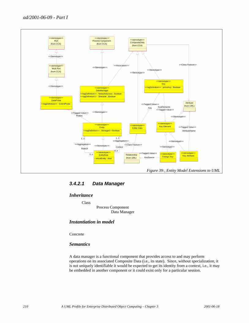
ad/2001-06-09 - Part I
210 A UML Profile for Enterprise Distributed Object Computing – Chapter 3 2001-06-18
Entity <<tagDefinition>> - Managed = Boolean
<<stereotype>>
EntityRole - virtualEntity : bool
<<stereotype>> <<Stereotype>>
Process Component (from CCA)
<<stereotype>> Port
(from CCA) <<stereotype>>
CompositeData (from CCA)
<<stereotype>>
DataProbe <<tagDefinition>> - ExtentProbe
<<stereotype>>
Key <<tagDefinition>> - primeKey : Boolean
<<stereotype>>
DataManager <<tagDefinition>> - NetworkAccess : Boolean <<tagDefinition>> - Sharable : Boolean
<<stereotype>>
<<Association>> <<Stereotype>>
<<Stereotype>>
Entity Data <<stereotype>>
<<Stereotype>>
Attribute (from UML)
Key Attribute <<stereotype>>
AttributeName <<Tagged Value>>
Foreign Key <<stereotype>>
Key Element <<stereotype>>
Relationship (from UML)
<<Stereotype>>
<<Stereotype>>
<<Stereotype>>
<<Stereotype>> Probes <<Tagged Value>> Key
<<Tagged Value>> KeyElements
<<Tagged Value>>
Multi Port (from CCA)
<<stereotype>>
<<Stereotype>>
<<Stereotype>>
<<Class Feature>>
KeySource <<Tagged Value>>
<<Class Feature>> RoleOf
0..n
1..1 <<Aggregation>>
Context 0..n
1..1 <<Aggregation>>
Figure 39:, Entity Model Extensions to UML
3.4.2.1 Data Manager
Inheritance
Class Process Component
Data Manager
Instantiation in model
Concrete
Semantics
A data manager is a functional component that provides access to and may perform operations on its associated Composite Data (i.e., its state). Since, without specialization, it is not uniquely identifiable it would be expected to get its identity from a context, i.e., it may be embedded in another component or it could exist only for a particular session.
ad/2001-06-09 - Part I
2001-06-18 A UML Profile for Enterprise Distributed Object Computing – Chapter 3 211
Tagged values
Network Access:
A Boolean property that expresses whether the implementation would be expected to have a network accessible interface.
Sharable:
A Boolean property that indicates if the implementation can be shared across multiple sessions and/or in by concurrent transactions..
Manages:
A reference to the associated Composite Data specification.
Constraints
N/A
Diagram notation
Equivalent to Class
3.4.2.2 Entity Data
Inheritance
Class Composite Data
Entity Data
Instantiation in a model
Concrete
Semantics
Entity Data is the data structure that represents a concept in the business domain. It is equivalent to an entity in data modelling or a relation in a relational database. In a Data Manager or its specializations, such as Entity, it represents the state of an object.
Entity Data has attributes (from Data Element) and relationships. The information viewpoint is a viewpoint on Entity Data elements.
ad/2001-06-09 - Part I
212 A UML Profile for Enterprise Distributed Object Computing – Chapter 3 2001-06-18
Tagged values
Key:
A reference to the associated Key specification(s).
Constraints
• Entity Data must have a prime Key that is unique within the extent of the Entity Data type (i.e., the type and all sub-types).
• Entity Data is managed by an Entity Data Manager.
Diagram notation
None
3.4.2.3 Key
Inheritance
Class Composite Data
Key
Instantiation in a model
Concrete
Semantics
A Key is a value that may be used to identify a Data Entity for some purpose. Generally, it will be a unique identifier within some context. A Key designated Prime Key = true is the key intended for unique identity of the Data Entity within the extent of the Data Entity type.
A Key is composed of key elements which may be selected attribute values of the associated Data Entity or Foreign Keys. A Foreign Key is the key of a related Date Entity.
Tagged values
Prime Key
A Boolean value that indicates if the Key is intended to be the primary unique identity of the associated Entity Data type. If so, the value must be unique within the extent of the identifiable type.
Key Elements
A list of key elements consisting of references to attributes and relationships of the associated Entity Data .
ad/2001-06-09 - Part I
2001-06-18 A UML Profile for Enterprise Distributed Object Computing – Chapter 3 213
Constraints
• If Key is Prime Key = true, then the value must be unique within the extent of the associated Entity Data type and its sub-types.
• The attributes that are incorporated into the key must be immutable.
• The Key Elements that comprise the key have an immutable sequence.
Diagram notation
Similar to Class
3.4.2.4 Key Element
Inheritance
Attribute Key Element
Instantiation in a model
Abstract
Semantics
A Key Element is one segment of a Key, which is either a reference to an attribute of the associated Data Entity or a reference to the key of an associated Data Entity.
Tagged values
N/A
Constraints
N/A.
Diagram notation
N/A
3.4.2.5 Foreign Key
Inheritance
Attribute Key Element
Foreign Key
ad/2001-06-09 - Part I
214 A UML Profile for Enterprise Distributed Object Computing – Chapter 3 2001-06-18
Instantiation in a model
Concrete
Semantics
A Foreign Key is a Key Element that contains a reference to a related Entity Data structure. The subject Entity Data structure derives its identity, in part, from the prime key of the related Entity Data structure. For example, the line item of an order may be uniquely identified by the line number and the key of the associated order. The Foreign Key element references the relationship in order to identify the related Entity Data that contains the Foreign Key value.
Tagged values
KeySource
A reference to the relationship through which the value and structure of the foreign key are derived.
Constraints
• The related Entity Data must have a prime key.
• If the containing Key is designated PrimeKey = true, then the relationship for the KeySource must be immutable.
Diagram notation
Attribute
3.4.2.6 Key Attribute
Inheritance
Attribute Key Element
Key Attribute
Instantiation in a model
Concrete
Semantics
A Key Attribute identifies an attribute of the associated Entity Data that is included as an element of the Entity Data key. The value of the attribute becomes an element of the key of an instance of the Entity Data type.
ad/2001-06-09 - Part I
2001-06-18 A UML Profile for Enterprise Distributed Object Computing – Chapter 3 215
Tagged values
AttributeName
The identity of the attribute in the associated Entity Data that is incorporated as an element of the Key
Constraints
• If the containing Key is designated PrimeKey = true, then the Attribute values that are incorporated into the key must be immutable.
Diagram notation
Attribute
3.4.2.7 Entity
Inheritance
Class Process Component
Data Manager Entity
Instantiation in a model
Concrete
Semantics
An Entity is an object representing something in the real world of the application domain. It incorporates Entity Data that represents the state of the real world thing, and it provides the functionality to encapsulate the Entity Data and provide associated business logic.
An Entity instance has identity derived from the Key of its associated Entity Data.
Entity is the abstract super type of all identifiable application domain elements. This includes Entities that have a collection of rules to operate on the state of related entities. It also includes Entities that incorporate process elements that act on other Entities. The rule set and process specializations introduce additional elements, but have the basic characteristics of being identifiable, having local state (Composite Data) often viewed as their “context,” and having relationships to other Entities that they may act upon.
If an Entity is managed, all instances of the type and its sub-types are known, each instance has unique identity, and the type can have operations and attributes associated with the extent (i.e., applicable to all instances). This is typically implemented as a type manager or “home” object that represents the extent.
ad/2001-06-09 - Part I
216 A UML Profile for Enterprise Distributed Object Computing – Chapter 3 2001-06-18
Tagged values
In the list, below, only Managed is introduced as a tagged value by Entity, but NetworkAccess and Sharable, inherited from Data Manager, are also discussed to clarify the implications.
Probes
Identifies Data Probe ports associated with the Entity type.
Managed
A Boolean value that indicates if the Entity type is managed. If it is managed, then the implementation provides a mechanism for accessing the extent of all instances of the type and its sub-types and may provide a mechanism for dynamically applying rules to all instances. This typically is implemented as a “home” or “type manager.”
NetworkAccessible
A Boolean value that indicates if the Entity is expected to be accessed over the network. This implies that it has a network interface (e.g., CORBA IDL). An Entity that is not NetworkAccessible can only be accessed over the network through an associated Entity that is NetworkAccessible.
Sharable
A Boolean value that indicates if the Entity can be shared by multiple, concurrent transactions or users. A Sharable Entity will enforce controls to serialize access by concurrent transactions.
An Entity that is not sharable may be instantiated for use by a particular user or transaction. It generally contains a copy of the primary Entity Data instance representing the real world thing. The primary Entity Data instance may be in a database and the copy is created to perform operations on the Entity Data. Alternatively, the Entity Data may be managed by an Entity that is sharable, but the copy is created so that processing can be localized on another server. In either case, it would be expected that the primary Entity Data would be locked when the copy is taken and released when the copy is deleted. Changes to the copy would likely be applied to the primary instance prior to removing the lock.
Entities that are not sharable may also be implemented as value objects, which are always passed by value over the network. While they may have unique identity by association with an identifiable Entity, they may not have a key that reflects this unique identity and their Entity Data does not carry its unique identity when passed by value.
An Entity that is sharable is expected to be persistent. An Entity that is not sharable may be persistent if it is incorporated in the state of a sharable Entity.
Constraints
• An Entity manages Entity Data, which may have a key and relationships.
• A managed Entity must have a Primary Key.
ad/2001-06-09 - Part I
2001-06-18 A UML Profile for Enterprise Distributed Object Computing – Chapter 3 217
• A network Accessible Entity must have a Primary Key
• An Entity that is Sharable will serialize concurrent transactions that attempt to access its data.
Diagram notation
Equivalent to Class
3.4.2.8 Entity Role
Inheritance
Class Process Component
Data Manager Entity
Entity Role
Instantiation in a model
Concrete
Semantics
An Entity Role extends its parent Entity for participation in a particular context. An Entity may have a number of associated Entity Roles reflecting participation in multiple contexts. The Entity might have several Entity Roles of the same type at the same time, but each should be associated with a different context.
The context of an Entity Role is also represented by an Entity. The context could be a corporation where the parent is a person and the Entity Role is an employee. A context may have many entity roles of the same type or different types representing participation of different parent Entities for different purposes.
Tagged values
VirtualEntity
A Boolean value that indicates if the Entity Role incorporates and extends the primary interface of the parent Entity it represents, i.e., it can be used in place of the primary Entity.
Constraints
The parent entity of an entity role cannot be dynamically changed.
Diagram notation
Equivalent to Class
ad/2001-06-09 - Part I
218 A UML Profile for Enterprise Distributed Object Computing – Chapter 3 2001-06-18
3.4.2.9 Data Probe
Inheritance
Class Proto Port
Port MultiPort
Data Probe
Instantiation in a model
Concrete
Semantics
A Data Probe port is associated with an Entity and accepts ad hoc requests to detect changes in the internal state of the Entity. The Data Probe then forwards messages or events when the states of interest become true until the request is removed. A Data Probe may serve many requests concurrently, producing various message types when the appropriate states occur.
Tagged values
ExtentProbe
ExtentProbe = true indicates that requests apply to the extent of the associated entity as opposed to a particular instance. In implementation, an ExtentProbe would be associated with a “home” or “type manager.”
Constraints
• DataProbes only emit messages (i.e., output only).
• DataProbe can only attach to an Entity with Managed = true..
Diagram notation
Same as Port (from CCA).
ad/2001-06-09 - Part I
2001-06-18 A UML Profile for Enterprise Distributed Object Computing – Chapter 3 219
4. The Events Profile
The Events profile describes a set of UML extensions that may be used on their own, or in combination with the other EDOC elements, to model event driven systems;
4.1 Rationale
4.1.1 Introduction
Event driven computing is becoming the preferred distributed computing paradigm in many enterprises and in many collaborations between enterprises.
Event driven computing combines two kinds of loosely coupled architectures:
• Event driven process architecture. This is a loosely coupled process architecture where the activities are not sequenced in traditional workflow fashion. Rather each participant in the process has autonomous responsibilities and performs those responsibilities on the basis of loosely coupled notifications, (in the supply chain world a.k.a. business signals).
• Publish and subscribe information distribution architecture. Publish and Subscribe is a loosely coupled mechanism for getting information from publishers to subscribers, while keeping the two independent of each other. Publish and subscribe is often implemented as loosely coupled, distributed components that communicate with each other through asynchronous messaging.
In event driven computing the most important aspect of the business process is the events that happen during its execution, and the most important part of the component-to-component communication is the notification of such events from the component that made them happen to all the components that need to react to them.
In ECA we support both the definition of loosely coupled event-driven business processes, and the loosely coupled publish and subscribe communication between distributed components.
Neither the business world, nor the computing world, however, applies only one paradigm to their problem space. Businesses use a combination of loosely coupled and tightly coupled business processes and computing solutions deploy a combination of loosely coupled and tightly coupled styles of communication and interaction between distributed components.
This document describes in detail the event-driven flavor of loosely coupled business and systems models, and also illustrates how such models can co-habit with more tightly coupled models.
An ECA based business process can be defined as event driven for some of its steps and workflow or request/response driven for others. Likewise, distributed components in the ECA component profile can be configured to communicate with each other in a mixture of publish-and-subscribe, asynchronous Point-to-Point, and client-server remote invocation styles.
This document will focus on the purely event driven paradigm.
ad/2001-06-09 - Part I
220 A UML Profile for Enterprise Distributed Object Computing – Chapter 3 2001-06-18
We will cover the following topics:
• Design Rationale
• Event driven business model
• Event driven computing
• Event driven business computing
• Publish and Subscribe
• Key Concepts of event driven business and system models
• Metamodel for specifying event driven business systems
• UML Profile for the Metamodel
• Relationship to other ECA profiles
• Relationship to other paradigms
• Applicability and leverage of event driven models
4.1.2 Overall design rationale
This profile is based on the following design principles:
• Alignment with the BOI roadmap (BOM/98-12-04) with respect to business process, business entity, business event, and business rule.
• The event as a central rather than peripheral concept.
• Business Processes should be loosely coupled:
− Autonomy of participants in a business process
− Distinction between process and entity
− Clear separation of business logic, i.e. rules from business execution, i.e. the action taken once rules have been resolved.
• Information distribution should be loosely coupled
− Use of Publish and Subscribe rather than point-to-point
− Ubiquitous event notification
− Asynchronous computing
− Shared information model
• Loose coupling of the Events profile with the Business Processes profile, Entities profile, and component profile
• Re-usability of paradigm
− Recursive use of event notifications
• Applicability under multiple paradigms
− The Events profile is intended to support both business process modeling and EAI.
− The proposed profile is intended for either tightly coupled client/server or peer-to-peer computing, or loosely coupled event-driven computing, or combinations of both.
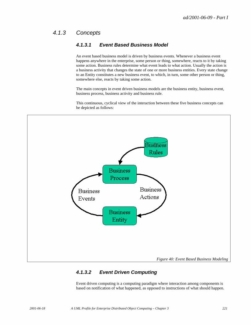
ad/2001-06-09 - Part I
2001-06-18 A UML Profile for Enterprise Distributed Object Computing – Chapter 3 221
4.1.3 Concepts
4.1.3.1 Event Based Business Model
An event based business model is driven by business events. Whenever a business event happens anywhere in the enterprise, some person or thing, somewhere, reacts to it by taking some action. Business rules determine what event leads to what action. Usually the action is a business activity that changes the state of one or more business entities. Every state change to an Entity constitutes a new business event, to which, in turn, some other person or thing, somewhere else, reacts by taking some action.
The main concepts in event driven business models are the business entity, business event, business process, business activity and business rule.
This continuous, cyclical view of the interaction between these five business concepts can be depicted as follows:
Figure 40: Event Based Business Modeling
4.1.3.2 Event Driven Computing
Event driven computing is a computing paradigm where interaction among components is based on notification of what happened, as opposed to instructions of what should happen.
ad/2001-06-09 - Part I
222 A UML Profile for Enterprise Distributed Object Computing – Chapter 3 2001-06-18
“What happened” is reflected as events. The communication that the event happened is reflected as notifications. The reaction to the notification (or indirectly to the event) is reflected as activities.
Two important layers provide loose coupling between event, notification and activity.
The events are decoupled from the act of notification by configurable subscriptions.
The act of notification is decoupled from the activity by configurable notification rules.
Event driven computing is a very flexible, yet powerful architecture for enterprise distributed object computing. The main architectural principle is that individual components are kept as autonomous as possible, and that the loose coupling and configuarability enable rapid reconfiguration of the system to meet changing business model requirements such as mergers, outsourcing and business re-engineering. Under event driven enterprise computing all business entities are self-contained, and typically do not directly change each other’s state.
4.1.3.3 Event Driven Business Computing
Event driven business computing is a paradigm that executes business processes by capturing events that happen in the enterprise, notifying the appropriate other parties in the enterprise or outside the enterprise, and reacting to such notifications.
Business processes are configured with a set of subscriptions, and a set of notification rules that determine what activity to start (or end) based on each notification.
Business Entities are the people, products, and other business resources and artifacts that business activities operate on. When actions are performed on Business Entities, Business Events happen. All Business Entities are capable of notifying the world of events that happen to them.
Business Processes that are capable of subscribing to such event notifications are called EventBasedProcesses. They assign notifications to activities based on a set of Notification Rules.
4.1.3.4 Publish and Subscribe
In a Publish and Subscribe information distribution model, publishers publish information, and subscribers subscribe to information. Publishing simply means make the information openly available for consumption. Subscribing simply means expressing an interest in the information and consuming it when it gets delivered. The information is transferred from Publisher to Subscriber ‘automatically’, usually through the use of asynchronous message middleware. Publishers do not know which subscribers will receiver their data, and subscribers do not know where the information comes from. The information, however, describes the state of a process or an entity that is of interest to both publisher and subscriber, and both parties share the information model that describes these states (and state changes).
ad/2001-06-09 - Part I
2001-06-18 A UML Profile for Enterprise Distributed Object Computing – Chapter 3 223
4.1.4 Key Concepts of event driven business and system models
4.1.4.1 EventBasedProcess
This is a concept introduced by this ECA Events profile, but based on the Choreography element in the ECA component profile.
EventBasedProcesses are identifiable series of activities that change states of business entities, thereby causing business events. For example, the activities in the Shipping process may cause allocation events against the Inventory Entity, and pick, pack, and ship events against the Shipment Entity.
4.1.4.2 Entity
This is a concept from the Entities profile.
Business Entities are representations of entities of significance to the business, identifiable by an ID, operated on during business process execution, and characterized by having a lifecycle expressed as a set of entity states. Examples are Customer, Purchase Order, Product, and Payment. In the Events profile, we use the supertype of Entity, DataManager, as the managers of the data behind an Entity. An EventBasedDataManager is capable of publishing information about all changes to the data it manages. Because a EventBasedDataManager is a kind of EventBasedProcess, it can also publish information about state changes in its internal process.
4.1.4.3 BusinessEvent
This is a concept introduced by this ECA Events profile.
BusinessEvents are state changes whose occurrence is of significance to the execution of business processes. Typically business events reflect state changes in Business Entities. These can be thought of as entity events. Examples are the approval of a Purchase Order, or Receipt of a Payment. A more indirect type of business event is a state change to a business process or to a collaboration between two business processes. These are called ProcessEvents.
4.1.4.4 Notification
This is a concept introduced by this ECA Events profile. This is a concept only, it is not represented by a specific element in the Events profile. It is implemented using the dataflow part of the Business Processes profile.
A notification is a triggered dataflow between two roles, or between two components. The trigger that causes the notification can be ‘manual’, or timed, or it can be due to the fact that an event has happened. When triggered by an event, it is called an event notification. Event notification, too, is just a concept, and not modeled explicitly.
The notification is always one-way only. The source of the notification is usually an Entity, but can also be an EventBasedProcess. The destination is usually an EventBasedProcess.
A notification can be thought of as the delivery of a set of data from a publisher to a subscriber. The data delivered is a PubSubNotice. A PubSubNotice is just a set of data, it is immutable, and it does not have any behavior of its own. There is no implication in the
ad/2001-06-09 - Part I
224 A UML Profile for Enterprise Distributed Object Computing – Chapter 3 2001-06-18
PubSubNotice as to what the recipient is going to do when it receives the PubSubNotice. An EventNotice is a special kind of PubSubNotice.
All business events are associated with an EventNotice and the corresponding notification will be take place whenever the business event happens successfully.
Similarly, when a business event is supposed to have happened but didn’t, ‘failure’ notifications will be take place.
An EventNotice always conveys the following information:
• the EventBasedProcess or entity the event happened against,
• the trigger that caused it,
• the identification of the before state,
• the after state,
• the change between the two states
4.1.4.5 Publisher
This is a concept introduced by this ECA events profile.
A publisher is a component that provides PubSubNotices.
4.1.4.6 Subscriber
This is concept introduced by this ECA Events profile.
A subscriber is a role or component that holds subscriptions to one or more PubSubNotices.
4.1.4.7 Subscription
This is a concept introduced by this ECA Events profile.
A subscription establishes a flow of PubSubNotices to the subscriber. A subscription identifies the type of EventNotice, e.g. the kind of event you want to be notified about. A subscription may additionally have a SubscriptionClause associated. The SubscriptionClause functions as a filter much like a where-clause on the content of the notification.
4.1.4.8 NotificationRule
This is a concept introduced by this ECA Events profile.
NotificationRules are rules that govern the execution of (part of) an EventBasedProcess. A NotificationRule is a mapping from a BusinessNotification to an activity, optionally guarded by a EventCondition. An EventCondition is a dependency on the receipt of additional, related PubSubNotices.
ad/2001-06-09 - Part I
2001-06-18 A UML Profile for Enterprise Distributed Object Computing – Chapter 3 225
4.1.5 Event and Notification based Interaction Models
So the basic building blocks are the EventBasedProcess and the Entity, as shown in figure 1. The two are ‘wired together’ by a flow of actions from process to entity, and by a flow of EventNotices from entity to process. In a component framework, therefore, EventBasedProcesses have EventNotices inflow and action outflow, and Entities have action inflow and EventNotice outflow. A messaging infrastructure manages the delivery of EventNotices from entities to processes. The actions too, incidentally, can be implemented via a messaging infrastructure, but the corresponding messages are usually point-to-point.
This means that we can create CCA EventBasedProcess components and CCA event-based Entity components if we can model:
• A EventBasedProcess as a set of Notification Rules of the type notification/condition/activity (This is the event-driven equivalent of the commonly known even/condition/action rule).
• An event-based Entity as set of action/state/event causalities.
The connection from EventBasedProcess to Entity is governed by a configurable mapping of notification to action, namely the notification rule.
The connection from Entity to EventBasedProcess is governed by a configurable set of subscriptions.
With these building blocks we can model a number of event-based interactions. And by reconfiguring the Notification Rules and/or the Subscriptions, we can easily re-engineer the business process and its execution in the system.
The very simplest model is a single process affecting a single entity, but this is not very interesting.
The simplest model of interest is a single process affecting multiple entities.
A slightly more complex interaction is process-to-process notifications. This model is used in supply chain models, a.k.a. business signal.
Another flavor of interaction is the delegation of the responsibility to deal with notifications. This model is used in EAI integration where legacy applications can be “wrapped” behind publishers and subscribers of notifications.
These three flavors map to three kinds of interaction in the component model: Interaction between a master and slave component, interaction between two peer components, and interaction between the boundary of a component and its subcomponents.
Yet another kind of interaction that can also be based on events and notifications is a collaboration between processes. This model is used often in b2b interactions. Even web services can be implemented using event concepts and loosely coupled messaging.
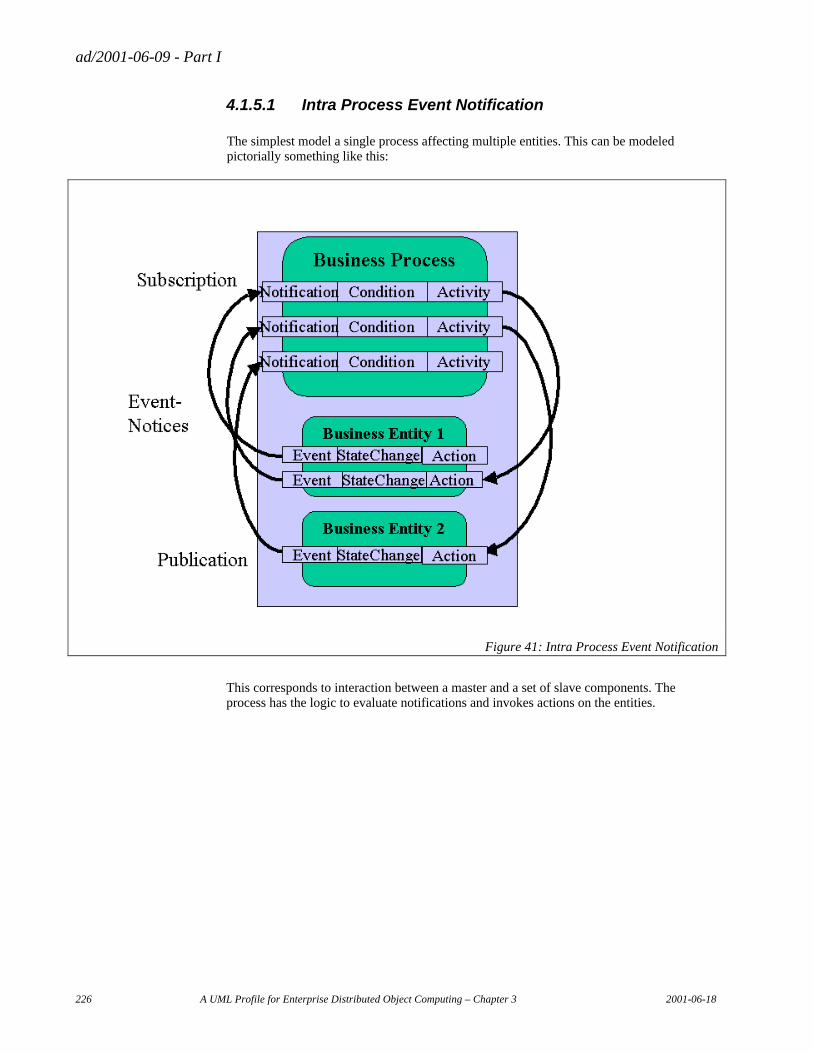
ad/2001-06-09 - Part I
226 A UML Profile for Enterprise Distributed Object Computing – Chapter 3 2001-06-18
4.1.5.1 Intra Process Event Notification
The simplest model a single process affecting multiple entities. This can be modeled pictorially something like this:
Figure 41: Intra Process Event Notification
This corresponds to interaction between a master and a set of slave components. The process has the logic to evaluate notifications and invokes actions on the entities.
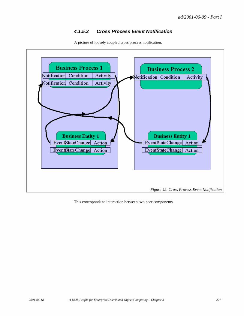
ad/2001-06-09 - Part I
2001-06-18 A UML Profile for Enterprise Distributed Object Computing – Chapter 3 227
4.1.5.2 Cross Process Event Notification
A picture of loosely coupled cross process notification:
Figure 42: Cross Process Event Notification
This corresponds to interaction between two peer components.
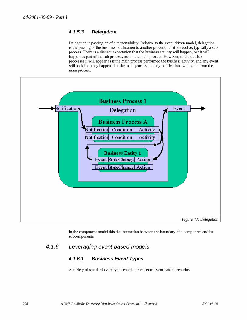
ad/2001-06-09 - Part I
228 A UML Profile for Enterprise Distributed Object Computing – Chapter 3 2001-06-18
4.1.5.3 Delegation
Delegation is passing on of a responsibility. Relative to the event driven model, delegation is the passing of the business notification to another process, for it to resolve, typically a sub process. There is a distinct expectation that the business activity will happen, but it will happen as part of the sub process, not in the main process. However, to the outside processes it will appear as if the main process performed the business activity, and any event will look like they happened in the main process and any notifications will come from the main process.
Figure 43: Delegation
In the component model this the interaction between the boundary of a component and its subcomponents.
4.1.6 Leveraging event based models
4.1.6.1 Business Event Types
A variety of standard event types enable a rich set of event-based scenarios.
ad/2001-06-09 - Part I
2001-06-18 A UML Profile for Enterprise Distributed Object Computing – Chapter 3 229
Success events
A success event is the ‘normal’ event. It reflects the successful execution of an action on an entity or the successful initiation or completion of an activity within the process.
Failure events
A failure event is a type of ‘exception’ event. It reflects that an action on an entity was attempted but failed, or that the initiation of an activity failed, or that an activity was forced to terminate unsuccessfully. In programming languages this is the equivalent of ‘raising an exception’.
TimeOut-Events
This is one of the most useful events for management. A TimeOut-event is an abstract event that reflects that something should have happened within a certain time period, but didn’t. Typically this would be something like ‘shipment was scheduled but did not happen’ within the allotted time. This can be generated based on an overdue condition relative to a scheduled time
Mutual exclusion events
This type of event signifies that a given event that might be expected according to the business process, did not happen, due to another alternative event happening. This may be due to the process calling for a mutually exclusive choice between two parallel events, or based on the occurrence of an event that normally happens after the event in question, indicating that an event was ‘skipped’.
Data change events
These are useful for replication of data from one place to another. Whenever the source data changes, events are generated, even if the change in data is not considered an event in an entity life cycle sense.
Timed notifications
This is in some sense the simplest kind of notification; it is simply an alarm clock or planning calendar. You can schedule notifications based on a schedule of trigger times. The event, in some sense, is the clock reaching the scheduled time. The notification is usually about the state of something as per that time, or in some cases it could be the timed release of a number of accumulated event notifications.
4.1.6.2 Event Algebra
Events may be ANDed/ ORed, included, excluded, to create new event types.
For instance creditApproved event, and shipmentReady event may be ANDed to releaseApproved event.
For instance orderApproved event and NOT licenseDenied event may be ANDed to shipmentReleased event.
ad/2001-06-09 - Part I
230 A UML Profile for Enterprise Distributed Object Computing – Chapter 3 2001-06-18
For instance orderShipped event, and NOT shipmentInvoiced event may be ANDed to invoice exception event.
For instance orderShipped event and orderCanceled event may be ORed to produce an orderClosed event.
Such event algebra is performed by value-added event agents. They take event notifications as their input and produce value added event notifications as their output.
Such an agent could also be turning event notifications into time-released notifications.
4.1.6.3 Management by Exception
One of the most important ways to leverage event driven computing is to manage by exception notifications. If the business model defines all the events that should occur in the normal course of business, then intelligent agents can be set up to track the progress of each process instance and issue notifications whenever something happened too late or didn’t happen at all. These agents would issue timeout-event notifications, mutual exclusion event notifications, and other exception notifications.
Event notifications can also be used to monitor workloads and to give input for rebalancing of loads within a process.
4.2 Metamodel
This is a meta-model for event-driven business computing, specifying the concepts described above. The model consists of two packages:
• Publish and Subscribe Package
• Event Package
These two packages are described in detail below, but first we show two views across the packages:
• Process View (showing how a Business Process produces and reacts to events)
• Entity View (showing how Business Entities produce and react to events)
We also show both packages and both views together in a full overview diagram of the metamodel for the Events profile.
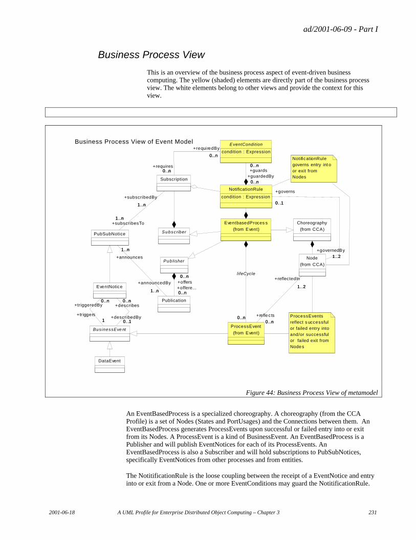
ad/2001-06-09 - Part I
2001-06-18 A UML Profile for Enterprise Distributed Object Computing – Chapter 3 231
Business Process View
This is an overview of the business process aspect of event-driven business computing. The yellow (shaded) elements are directly part of the business process view. The white elements belong to other views and provide the context for this view.
Business Process View of Event Model
ProcessEvents
reflect s uccessful
or failed entry into
and/or successful or failed exit from
Nodes
Pub lisher
EventNotice
BusinessEve nt
0..n
1
+triggeredBy0..n
+tr iggers1
0..n
0. .1
+describes0..n
+describedBy0. .1
DataEvent
Notifi cationRule
governs entry int o
or exit from Nodes
Publication
0..n
0..n
+offers0..n
+offere...0..n
PubSubNotice
1. .n
1..n
+announcedBy
1. .n
+announces
1..n
Subscriber
Choreography
(from CCA)
ProcessEvent
(from Event)
E ventCondition
condition : Expression
EventbasedProces s
(from Event)
0..n0..n
lifeCycle
Subscription
1..n
1..n
+subscribedBy
1..n
+subscribesTo1..n
0..n
0. .n
+requi redBy
0..n
+requires0. .n
Node
(from CCA)
1..2
0..n
+reflectedIn
1..2
+reflec ts
0..n
NotificationRule
condition : Expression
0. .n
0..n
+guardedBy0. .n
+guards0..n
1..2
0. .1
+governedBy
1..2
+governs
0. .1
Figure 44: Business Process View of metamodel
An EventBasedProcess is a specialized choreography. A choreography (from the CCA Profile) is a set of Nodes (States and PortUsages) and the Connections between them. An EventBasedProcess generates ProcessEvents upon successful or failed entry into or exit from its Nodes. A ProcessEvent is a kind of BusinessEvent. An EventBasedProcess is a Publisher and will publish EventNotices for each of its ProcessEvents. An EventBasedProcess is also a Subscriber and will hold subscriptions to PubSubNotices, specifically EventNotices from other processes and from entities.
The NotitificationRule is the loose coupling between the receipt of a EventNotice and entry into or exit from a Node. One or more EventConditions may guard the NotitificationRule.
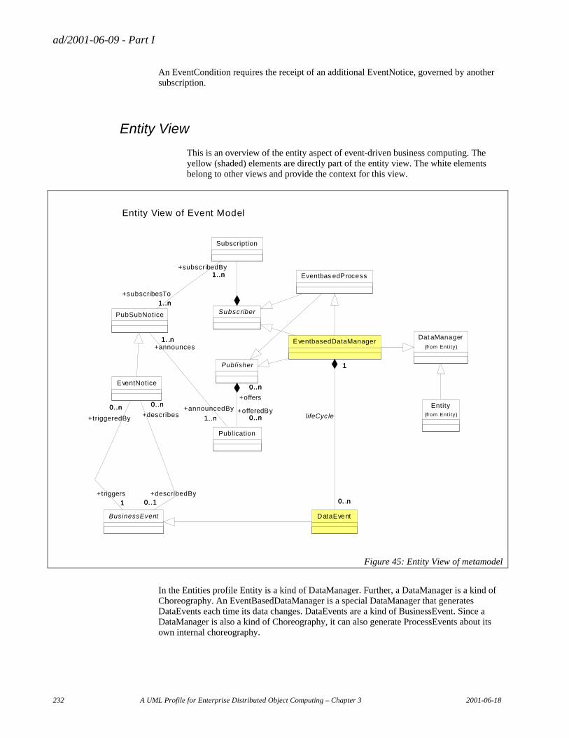
ad/2001-06-09 - Part I
232 A UML Profile for Enterprise Distributed Object Computing – Chapter 3 2001-06-18
An EventCondition requires the receipt of an additional EventNotice, governed by another subscription.
Entity View
This is an overview of the entity aspect of event-driven business computing. The yellow (shaded) elements are directly part of the entity view. The white elements belong to other views and provide the context for this view.
Entity View of Event Model
EventbasedDataManager
D ataEvent
1
0. .n
1
0. .n
lifeCyc le
EventNotice
BusinessEvent
0..n
1
+triggeredBy
0..n
+triggers1
0..n
0..1
+describes
0..n
+describedBy0..1
Subscriber
Subscription
PubSubNotice
1..n
1..n
+subscribedBy1..n
+subscribesTo1..n
Publisher
Publication
1..n
1. .n
+announcedBy
1..n
+announces1. .n
0..n
0..n
+offers
0..n
+offeredBy0..n
Eventbas edProcess
Entity(from Ent i ty)
Dat aManager(from Ent i ty)
Figure 45: Entity View of metamodel
In the Entities profile Entity is a kind of DataManager. Further, a DataManager is a kind of Choreography. An EventBasedDataManager is a special DataManager that generates DataEvents each time its data changes. DataEvents are a kind of BusinessEvent. Since a DataManager is also a kind of Choreography, it can also generate ProcessEvents about its own internal choreography.
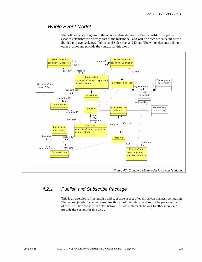
ad/2001-06-09 - Part I
2001-06-18 A UML Profile for Enterprise Distributed Object Computing – Chapter 3 233
Whole Event Model
The following is a diagram of the whole metamodel for the Events profile. The yellow (shaded) elements are directly part of the metamodel, and will be described in detail below, divided into two packages: Publish and Subscribe, and Event. The white elements belong to other profiles and provide the context for this view.
EventbasedD ataMan ager
DataEvent
1
0. .n
1
0. .n
li feCycle
PublisherDataManager
(from Entity)
BusinessEvent
EventNotice
(from Event)
1
0..n
+triggers
1
+triggeredBy
0..n
0..1
0..n
+describedBy0..1
+describes
0..n
CompositeData
(from CCA)
Publication
publicationClause : expression
domain : String
0..n
0..n
+offers
0..n
+offeredBy0..n
Subsc riber
PubS ubNotice
1..n
1..n+announcedBy
1..n+announces
1..n
EventCondition
condition : Expression
EventbasedProcess
Subscription
subs c riptionClause : expression
domain : String
1..n
1..n+subscribedBy
1..n
+subscribesTo
1..n
0..n
0..n+requi redBy
0..n+requires
0..n
Choreography
(from CCA)
ProcessEvent
entry : Booleansuccess : Boolean
0..n0..n
li feCycle
NotificationRule
condi ti on : Ex pression0..n
0..n +guardedBy
0..n+guards
0..n
Node
(from CCA)
1..2
0..n
+reflectedIn
1..2
+reflects
0..n
0..1
1. .2
+governs0..1
+governedBy1. .2
Figure 46: Complete Metamodel for Event Modeling
4.2.1 Publish and Subscribe Package
This is an overview of the publish and subscribe aspect of event-driven business computing. The yellow (shaded) elements are directly part of the publish and subscribe package. Each of them will be described in detail below. The white elements belong to other views and provide the context for this view.
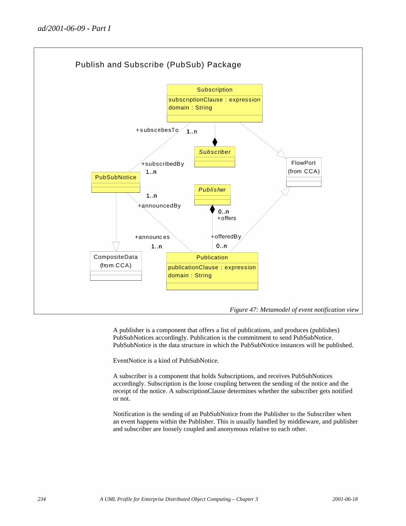
ad/2001-06-09 - Part I
234 A UML Profile for Enterprise Distributed Object Computing – Chapter 3 2001-06-18
Subscriber
Publisher
Subscription
subscriptionClause : expression
domain : String
Publication
publicationClause : expression
domain : String
0..n
0..n
+offers0..n
+offeredBy
0..n
PubSubNotice
1..n
1..n
+subscribedBy
1..n+ s ubscribesTo
1..n
1..n
1..n
+announcedBy
1..n
+announc es
1..n
Publish and Subscribe (PubSub) Package
FlowPort
(from CCA)
CompositeData
(from CCA)
Figure 47: Metamodel of event notification view
A publisher is a component that offers a list of publications, and produces (publishes) PubSubNotices accordingly. Publication is the commitment to send PubSubNotice. PubSubNotice is the data structure in which the PubSubNotice instances will be published.
EventNotice is a kind of PubSubNotice.
A subscriber is a component that holds Subscriptions, and receives PubSubNotices accordingly. Subscription is the loose coupling between the sending of the notice and the receipt of the notice. A subscriptionClause determines whether the subscriber gets notified or not.
Notification is the sending of an PubSubNotice from the Publisher to the Subscriber when an event happens within the Publisher. This is usually handled by middleware, and publisher and subscriber are loosely coupled and anonymous relative to each other.
ad/2001-06-09 - Part I
2001-06-18 A UML Profile for Enterprise Distributed Object Computing – Chapter 3 235
4.2.1.1 Publisher
Semantics
A publisher is a component that exposes a list of publications, and produces PubSubNotices accordingly
UML base element(s) in the Profile
Class
Fully Scoped name
EDOC::CCA::Event:: Publisher
Owned By
None
Properties
None
Related elements
Publication
Publisher offers one or more Publications
Constraints
None
4.2.1.2 Publication
Semantics
A Publication is a declaration of capability and intent to produce a PubSubNotice
UML base element(s) in the Profile
Inherits from FlowPort in CCA Profile
Fully Scoped Name
EDOC::CCA::Event:: Publication
ad/2001-06-09 - Part I
236 A UML Profile for Enterprise Distributed Object Computing – Chapter 3 2001-06-18
Owned By
Publisher
Properties
publicationClause
Expression based on attributes of PubSubNotice, describing the instance subset that will be produced according to this publication
domain
A domain in which the PubSubNotices for this publication will be produced
Related Elements
Publisher
A Publication is offeredBy exactly one Publisher
PubSubNotice
A Publication announces one or more PubSubNotices
FlowPort
A Publication Inherits from FlowPort as per the Component Profile
Constraints
PublicationClause Expression is constrained to the values of the attributes of the associated EventNotice
4.2.1.3 Subscriber
Semantics
A subscriber is a role or component that exposes a list of subscriptions, and consumes PubSubNotices accordingly
UML base element(s) in the Profile
Class
ad/2001-06-09 - Part I
2001-06-18 A UML Profile for Enterprise Distributed Object Computing – Chapter 3 237
Fully Scoped Name
EDOC::CCA::Event:: Subscriber
Owned By
None
Properties
None
Related elements
Subscription
A Subscriber holds one or more Subscriptions
Constraints
None
4.2.1.4 Subscription
Semantics
Subscription is the expression of interest in receiving and capability to receive a PubSubNotice.
UML base element(s) in the Profile
Inherits from FlowPort in Component Profile
Fully Scoped Name
EDOC::CCA::Event:: Subscription
Owned By
Subscriber
Properties
subscriptionClause
Expression based on attributes of PubSubNotice, describing the instance subset of interest to this subscription
ad/2001-06-09 - Part I
238 A UML Profile for Enterprise Distributed Object Computing – Chapter 3 2001-06-18
domain
A domain of interest. Only PubSubNotices produced within this domain are of interest
Related Elements
Subscriber
A Subscription is heldBy exactly one Subscriber
EventNotice
A Subscription subscribesTo one or more EventNotices
FlowPort
A Subscription Inherits from FlowPort as per Component Profile
Constraints
SubscriptionClause Expression is constrained to the values of the attributes of the associated EventNotice. If the subscription is for more than one event notice, the expression is constrained to attributes that are common to all the event notices of interest.
4.2.1.5 PubSubNotice
Semantics
A PubSubNotice is any data structure that is announcedBy a publication and/or subscribedTo by a subscription. Instances of PubSubNotice are communicated as DataFlows from publishers to subscribers based on the subscriptions.
UML base element(s) in the Profile
Inherits from CompositeData as per Entities profile
Fully Scoped Name
EDOC::CCA::Event:: PubSubNotice
Owned By
None
ad/2001-06-09 - Part I
2001-06-18 A UML Profile for Enterprise Distributed Object Computing – Chapter 3 239
Properties
None
Related Elements
Subscription
A PubSubNotice is subscribedBy one or more Subscriptions
Publication
A PubSubNotice announcedBy one or more Publications
CompositeData
A PubSubNotice Inherits from CompositeData as per Entities profile
Constraints
None
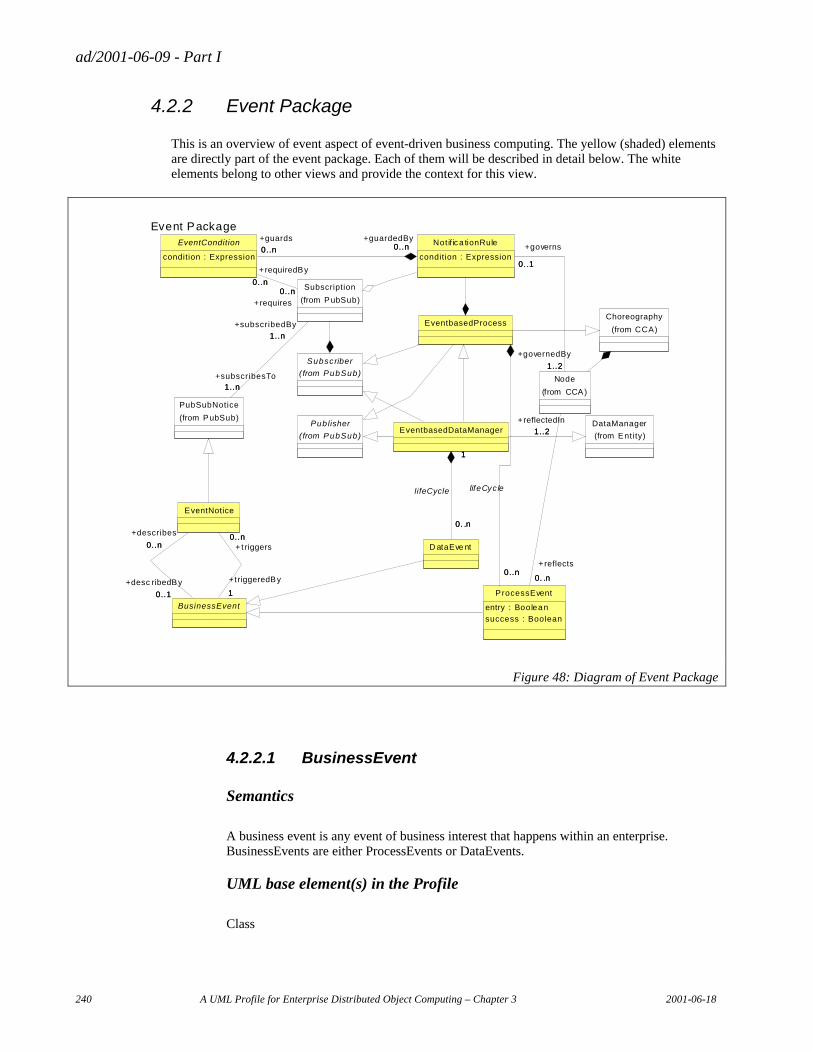
ad/2001-06-09 - Part I
240 A UML Profile for Enterprise Distributed Object Computing – Chapter 3 2001-06-18
4.2.2 Event Package
This is an overview of event aspect of event-driven business computing. The yellow (shaded) elements are directly part of the event package. Each of them will be described in detail below. The white elements belong to other views and provide the context for this view.
Publisher
(from PubSub)
DataManager
(from Entity)
BusinessEvent
EventNotice
1
0..n+ t riggers
1
+triggeredBy
0..n
0..1
0..n
+desc ribedBy
0..1
+describes
EventbasedDataManager
D ataEve nt
1
0. .n
1
0. .n
lifeCycle
Event Package
PubSubNotice
(from PubSub)
Subscriber
( from PubSub)
EventCondition
condition : Expression
EventbasedProcess
Subscription
(from PubSub)
1..n
1..n
+subscribedBy
1..n
+subscribesTo1..n
0..n0..n
+requiredBy
0..n
+requires
0..n
Choreography
(from CCA)
ProcessEvent
entry : Boolean
success : Boolean
0..n0..n
lifeCyc le
Notifica tionRule
condition : Expression0..n0..n
+guardedBy0..n
+guards
0..n
Node
(from CCA)
1..2
0. .n
+reflectedIn
1..2
+reflects
0. .n
0..1
1..2
+governs
0..1
+governedBy
1..2
0..n
Figure 48: Diagram of Event Package
4.2.2.1 BusinessEvent
Semantics
A business event is any event of business interest that happens within an enterprise. BusinessEvents are either ProcessEvents or DataEvents.
UML base element(s) in the Profile
Class
ad/2001-06-09 - Part I
2001-06-18 A UML Profile for Enterprise Distributed Object Computing – Chapter 3 241
Fully Scoped Name
EDOC::CCA::Event:: BusinessEvent
Owned By
None
Properties
None
Related Elements
EventNotice
A business event triggers one or more event notices
A business event is describedBy one or more event notices
ProcessEvent
Business event is the Abstract supertype of ProcessEvent
DataEvent
Business event is the Abstract supertype of DataEvent
Constraints
None
4.2.2.2 ProcessEvent
Semantics
A process event is any business event that reflects a state change within a process, i.e. entry into or exit from Nodes in a Choreography
UML base element(s) in the Profile
Inherits from BusinessEvent
Fully Scoped Name
EDOC::CCA::Event:: ProcessEvent
ad/2001-06-09 - Part I
242 A UML Profile for Enterprise Distributed Object Computing – Chapter 3 2001-06-18
Owned By
EventBasedProcess
Properties
None
Related Elements
Node
A ProcessEvent reflects the entry into or exit from one Node (or the exit from one and entry into another, i.e. two Nodes).
BusinessEvent
ProcessEvent Inherits from BusinessEvent
Constraints
Any Node referenced must belongs to the EventBasedProcess that also owns this ProcessEvent.
4.2.2.3 DataEvent
Semantics
A data event is any business event that reflects a changes in data managed by a DataManager
UML base element(s) in the Profile
Inherits from BusinessEvent
Fully Scoped Name
EDOC::CCA::Event:: DataEvent
Owned By
EventBasedDataManager
Properties
None
ad/2001-06-09 - Part I
2001-06-18 A UML Profile for Enterprise Distributed Object Computing – Chapter 3 243
Related Elements
BusinessEvent
ProcessEvent Inherits from BusinessEvent
Constraints
None
4.2.2.4 EventNotice
Semantics
An event notice is any PubSubNotice that is triggered by a business event.
UML base element(s) in the Profile
Inherits from PubSubNotice
Fully Scoped Name
EDOC::CCA::Event:: EventNotice
Owned By
None
Properties
None
Related Elements
BusinessEvent
An event notice is triggeredBy exactly one Business Event
An event notice may describe at most one Business Events
PubSubNotice
An event notice Inherits from PubSubNotice
Constraints
None
ad/2001-06-09 - Part I
244 A UML Profile for Enterprise Distributed Object Computing – Chapter 3 2001-06-18
4.2.2.5 EventBasedProcess
Semantics
An EventBasedProcess is a subtype of Choreography (CCA profile). It is a Subscriber and has NotificationRules associated with its Subscriptions. It is a Publisher and publishes ProcessEvents. ProcessEvents describe the life cycle of the EventBasedProcess.
UML base element(s) in the Profile
Inherits from Choreography (from CCA profile)
Fully Scoped Name
EDOC::CCA::Event:: EventBasedProcess
Owned By
None
Properties
None
Related Elements
ProcessEvent
An EventBasedProcess owns a set of ProcessEvents which together describes the life cycle of the EventBasedProcess
Choreography
An EventBasedProcess Inherits from Choreography (from CCA profile)
Publisher
An EventBasedProcess Inherits from Publisher
Subscriber
An EventBasedProcess Inherits from Subscriber
EventBasedDataManager
An EventBasedProcess is the supertype of EventBasedDataManager
ad/2001-06-09 - Part I
2001-06-18 A UML Profile for Enterprise Distributed Object Computing – Chapter 3 245
Constraints
None
4.2.2.6 EventBasedDataManager
Semantics
An EventBasedDataManager is a DataManager. It is also a Publisher and publishes DataEvents when its data changes. It may also be a subscriber, typically subscribing to PubSubNotices relating to the maintenance of its data, e.g. replication.
UML base element(s) in the Profile
Inherits from DataManager (from Entities profile)
Fully Scoped Name
EDOC::CCA::Event:: EventBasedDataManager
Owned By
None
Properties
None
Related Elements
DataEvent
An EventBasedDataManager owns a set of DataEvents which together describes possible changes to the data owned by the EventBasedDataManager
DataManager
An EventBasedDataManager Inherits from DataManager (from Entities profile)
Publisher
An EventBasedDataManager Inherits from Publisher
Subscriber
An EventBasedDataManager Inherits from Subscriber
ad/2001-06-09 - Part I
246 A UML Profile for Enterprise Distributed Object Computing – Chapter 3 2001-06-18
EventBasedDataManager
An EventBasedDataManager inherits from EventBasedProcess
Constraints
None
4.2.2.7 NotificationRule
Semantics
An NotificationRule is a rule associated with a subscription which determines what should happen within the EventBasedProcess holding the subscription when a qualifying PubSubNotice is delivered. Optionally the NotificationRule can be further guarded by an EventCondition that requires the delivery of additional events.
UML base element(s) in the Profile
Class
Fully Scoped Name
EDOC::CCA::Event:: NotificationRule
Owned By
EventBasedProcess
Properties
Condition
An Expression based on attributes of PubSubNotice, describing the instance subset of the PubSubNotice that will cause the change in the EventBasedProcess indicated by this NotificationRule
Related Elements
Subscription
A NotificationRule is associated with a Subscription and ‘fires’ upon receipt of the PubSubNotice associated with the Subscription.
EventCondition
A NotificationRule may be guardedBy one or more EventConditions calling for the receipt of additional events before this NotificationRule will ‘fire’ successfully.
ad/2001-06-09 - Part I
2001-06-18 A UML Profile for Enterprise Distributed Object Computing – Chapter 3 247
Node
A NotificationRule governs the entry into or exit from one Node (or the exit from one and entry into another, i.e. two Nodes).
Constraints
Any EventConditions must reference Subscriptions belonging to the same EventBasedProcess as the NotificationRule
4.2.2.8 EventCondition
Semantics
An EventCondition identifies a subscription and specifies a PubSubNotice instance subset of which one must have been received to satisfy this condion.
UML base element(s) in the Profile
Class
Fully Scoped Name
EDOC::CCA::Event:: EventCondition
Owned By
NotificationRule
Properties
Condition
An Expression based on attributes of PubSubNotice, describing the instance subset of the PubSubNotice that will satisfy the guard constituted by this EventCondition
Related Elements
Subscription
An EventCondition is requires a Subscription and ‘fires’ upon receipt of a PubSubNotice associated with the Subscription. If the received PubSubNotice satisfies the condition expression, then the EventCondition has been satisfied.
Constraints
None
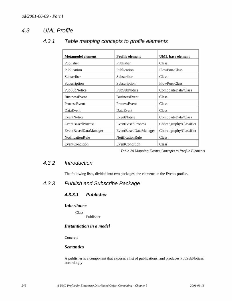
ad/2001-06-09 - Part I
248 A UML Profile for Enterprise Distributed Object Computing – Chapter 3 2001-06-18
4.3 UML Profile
4.3.1 Table mapping concepts to profile elements
Metamodel element Profile element UML base element
Publisher Publisher Class
Publication Publication FlowPort/Class
Subscriber Subscriber Class
Subscription Subscription FlowPort/Class
PubSubNotice PubSubNotice CompositeData/Class
BusinessEvent BusinessEvent Class
ProcessEvent ProcessEvent Class
DataEvent DataEvent Class
EventNotice EventNotice CompositeData/Class
EventBasedProcess EventBasedProcess Choreography/Classifier
EventBasedDataManager EventBasedDataManager Choreography/Classifier
NotificationRule NotificationRule Class
EventCondition EventCondition Class
Table 20 Mapping Events Concepts to Profile Elements
4.3.2 Introduction
The following lists, divided into two packages, the elements in the Events profile.
4.3.3 Publish and Subscribe Package
4.3.3.1 Publisher
Inheritance
Class Publisher
Instantiation in a model
Concrete
Semantics
A publisher is a component that exposes a list of publications, and produces PubSubNotices accordingly
ad/2001-06-09 - Part I
2001-06-18 A UML Profile for Enterprise Distributed Object Computing – Chapter 3 249
Tagged Values
offers
Reference: Publisher offers one or more Publications
Constraints
None
4.3.3.2 Publication
Inheritance
Class ProtoPort Port Flowport Publication
Instantiation in a model
Concrete
Semantics
A Publication is a declaration of capability and intent to produce a PubSubNotice
Tagged Values
publicationClause
Expression based on attributes of PubSubNotice, describing the instance subset that will be produced according to this publication
domain
A domain in which the PubSubNotices for this publication will be produced
Publisher
Reference: A Publication is offeredBy exactly one Publisher
announces
Reference: A Publication announces one or more PubSubNotices
ad/2001-06-09 - Part I
250 A UML Profile for Enterprise Distributed Object Computing – Chapter 3 2001-06-18
Constraints
PublicationClause Expression is constrained to the values of the attributes of the associated EventNotice
4.3.3.3 Subscriber
Inheritance
Class Subscriber
Instantiation in a model
Concrete
Semantics
A subscriber is a role or component that exposes a list of subscriptions, and consumes PubSubNotices accordingly
Tagged Values
holds
Reference: A Subscriber holds one or more Subscriptions
Constraints
None
4.3.3.4 Subscription
Inheritance
Class ProtoPort Port Flowport Subscription
Instantiation in a model
Concrete
Semantics
Subscription is the expression of interest in receiving and capability to receive a PubSubNotice.
ad/2001-06-09 - Part I
2001-06-18 A UML Profile for Enterprise Distributed Object Computing – Chapter 3 251
Tagged Values
subscriptionClause
Expression based on attributes of PubSubNotice, describing the instance subset of interest to this subscription
domain
A domain of interest. Only PubSubNotices produced within this domain are of interest
heldBy
Reference:A Subscription is heldBy exactly one Subscriber
subscribesTo
Reference: A Subscription subscribesTo one or more EventNotices
Constraints
SubscriptionClause Expression is constrained to the values of the attributes of the associated EventNotice. If the subscription is for more than one event notice, the expression is constrained to attributes that are common to all the event notices of interest.
4.3.3.5 PubSubNotice
Inheritance
Class CompositeData PubSubNotice
Instantiation in a model
Concrete
Semantics
A PubSubNotice is any data structure that is announcedBy a publication and/or subscribedTo by a subscription. Instances of PubSubNotice are communicated as dataflows from publishers to subscribers based on the subscriptions.
Tagged Values
subscribedBy
Reference: A PubSubNotice is subscribedBy one or more Subscriptions
ad/2001-06-09 - Part I
252 A UML Profile for Enterprise Distributed Object Computing – Chapter 3 2001-06-18
announcedBy
Reference: A PubSubNotice announcedBy one or more Publications
Constraints
None
4.3.4 Event Package 2
4.3.4.1 BusinessEvent
Inheritance
Class BusinessEvent
Instantiation in a model
Abstract
Semantics
A business event is any event of business interest that happens within an enterprise. BusinessEvents are either ProcessEvents or DataEvents.
Tagged Values
triggers
Reference: A business event triggers one or more event notices
describedBy
Reference: A business event is describedBy one or more event notices
Constraints
None
4.3.4.2 ProcessEvent
Inheritance
Class BusinessEvent ProcessEvent
ad/2001-06-09 - Part I
2001-06-18 A UML Profile for Enterprise Distributed Object Computing – Chapter 3 253
Instantiation in a model
Concrete
Semantics
A process event is any business event that reflects a state change within a process, i.e. entry into or exit from Nodes in a Choreography
Tagged Values
reflects
Reference: A ProcessEvent reflects the entry into or exit from one Node (or the exit from one and entry into another, i.e. two Nodes).
Constraints
Any Node referenced must belong to the EventBasedProcess that also owns this ProcessEvent.
4.3.4.3 DataEvent
Inheritance
Class BusinessEvent DataEvent
Instantiation in a model
Concrete
Semantics
A data event is any business event that reflects a changes in data managed by a DataManager
Tagged Values
None
Constraints
None
ad/2001-06-09 - Part I
254 A UML Profile for Enterprise Distributed Object Computing – Chapter 3 2001-06-18
4.3.4.4 EventNotice
Inheritance
Class CompositeData PubSubNotice EventNotice
Instantiation in a model
Concrete
Semantics
An event notice is any PubSubNotice that is triggered by a business event.
Tagged Values
triggeredBy
Reference: An event notice is triggeredBy exactly one Business Event
An event notice may describe at most one Business Events
Constraints
None
4.3.4.5 EventBasedProcess
Inheritance
Choreography EventBasedProcess
Instantiation in a model
Concrete
Semantics
An EventBasedProcess is a subtype of Choreography. It is a Subscriber and has NotificationRules associated with its Subscriptions. It is a Publisher and publishes ProcessEvents. ProcessEvents describe the life cycle of the EventBasedProcess.
Tagged Values
None
ad/2001-06-09 - Part I
2001-06-18 A UML Profile for Enterprise Distributed Object Computing – Chapter 3 255
Constraints
None
4.3.4.6 EventBasedDataManager
Inheritance
Choreography ProcessComponent DataManager EventBasedDataManager
Instantiation in a model
Concrete
Semantics
An EventBasedDataManager is a DataManager. It is also a Publisher and publishes DataEvents when its data changes. It may also be a subscriber, typically subscribing to PubSubNotices relating to the maintenance of its data, e.g. replication.
Tagged Values
None
Constraints
None
4.3.4.7 NotificationRule
Inheritance
Class NotificationRule
Instantiation in a model
Concrete
Semantics
A NotificationRule is a rule associated with a subscription which determines what should happen within the EventBasedProcess holding the subscription when a qualifying PubSubNotice is delivered. Optionally the NotificationRule can be further guarded by an EventCondition that requires the delivery of additional events.
ad/2001-06-09 - Part I
256 A UML Profile for Enterprise Distributed Object Computing – Chapter 3 2001-06-18
Tagged Values
Condition
An Expression based on attributes of PubSubNotice, describing the instance subset of the PubSubNotice that will cause the change in the EventBasedProcess indicated by this NotificationRule
subscription
Reference: A NotificationRule is associated with a Subscription and ‘fires’ upon receipt of the PubSubNotice associated with the Subscription.
guardedBy
Reference: A NotificationRule may be guardedBy one or more EventConditions calling for the receipt of additional events before this NotificationRule will ‘fire’ successfully.
Node
A NotificationRule governs the entry into or exit from one Node (or the exit from one and entry into another, i.e. two Nodes).
Constraints
Any EventConditions must reference Subscriptions belonging to the same EventBasedProcess as the NotificationRule
4.3.4.8 EventCondition
Inheritance
Class EventCondition
Instantiation in a model
Concrete
Semantics
An EventCondition identifies a subscription and specifies a PubSubNotice instance subset of which one must have been received to satisfy this condition.
ad/2001-06-09 - Part I
2001-06-18 A UML Profile for Enterprise Distributed Object Computing – Chapter 3 257
Tagged Values
Condition
An Expression based on attributes of PubSubNotice, describing the instance subset of the PubSubNotice that will satisfy the guard constituted by this EventCondition
requires
Reference: An EventCondition is requires a Subscription and ‘fires’ upon receipt of a PubSubNotice associated with the Subscription. If the received PubSubNotice satisfies the condition expression, then the EventCondition has been satisfied.
Constraints
None
4.4 Relationship to other ECA profiles
4.4.1 Relationship to Business Processes profile and Entities profile
The ECA Business Processes profile describes a process as a set of activities.
Activities are defined in terms of responsible party, performers, artifacts, and pre and post conditions.
Activity diagrams may be used to show roles and flow between activities.
Collaboration diagrams may be used to show roles and message flow between roles.
The Business Processes profile does not specify which performers act on what artifacts, and how.
It does not specify directly the relationship between states of artifacts and the pre and post conditions of activities.
It does not show directly what triggers each activity.
(Above three statements are qualified: other than as annotated in activity diagram as control flow and object flow.)
The Business Processes profile, relies on components to implement the choreography. The states and transitions of choreography implement the control flows of the activity diagram.
The messages implement the information flows from the collaboration diagram.
The Events profile (this profile) describes events that happen to artifacts (entities). It describes business events as changes from one state to another. The Events profile describes how activities result in state changes, i.e. events.
ad/2001-06-09 - Part I
258 A UML Profile for Enterprise Distributed Object Computing – Chapter 3 2001-06-18
It describes how these BusinessEvents map to EventNotices, and how subscriptions can channel notifications to processes, and how delivery of a EventNotice can be mapped by NotificationRules to activities.
The Events profile does not describe who or what within the process establishes the subscription, or who or what within the process reacts to receipts of notifications.
4.4.2 Relationship to ECA CCA profile
4.4.2.1 Modeling Events with Components
Events are changes in state to either entities or processes.
Just about anything that happens in a business, has interest to someone else, and so every event (to an entity or to a process) has the potential for causing notification.
At the system level this means that any process or entity has to offer notification (i.e. allow subscription) to any of its state change notifications.
Most event notifications also trigger rules of some kind. If state of inventory changes to 'below-minimum-stock-level' some re-order rule kicks in. If state of the order-process changes to 'over-due' then some expediting rule kicks in.
At the system level this means that NotificationRules and BusinessConditions must be able to refer to events.
All activities result in a new state, or in failure.
At the system level this means that definitions of activities and operations include postconditions. These postconditions could be either expressions of events (i.e. state change), or more likely expression of state (where the state change, or event, is implicit.).
The Events profile relies on the CCA profile to implement the outgoing event notification flows from an entity component, and the incoming event notification flows to a process component. Event notification flows happen from flow port to flow port.
The Events profile relies on the CCA profile to implement the linkage between (the completion of) an action on an entity and (an instance of) an event . The event model specifies which activity causes which event.
4.5 Relationship other paradigms
In general the central idea of event driven computing is that event notifications trigger action and/or communication, and that very little action or communication is not triggered by event notifications.
There are four main kinds of communication:
• Business notification: A one-way, information-only, notification. A special subtype is event-notification that informs that an event just happened. This is the main form of communication in event-driven computing.
ad/2001-06-09 - Part I
2001-06-18 A UML Profile for Enterprise Distributed Object Computing – Chapter 3 259
• Query: A two-way, request, response, with the response being the query result set. This is a more tightly coupled model. However a query could be triggered by the loosely coupled receipt of a business notification. Also the gathering of data for a business notification could require one or more tightly coupled queries.
• Collaboration: A two-way, negotiation-style, communication that may or may not result in a new state between the parties. An atomic style subtype is the ebXML business transaction. This could be implemented in many ways. One way is to consider the requests and responses in the collaboration to simply be business notifications. Regardless how the collaboration itself is implemented, it could certainly be triggered by the loosely coupled receipt of a business notification. For instance notification of an event within the enterprise might trigger the collaboration to order more inventory.
• Method invocation: A one-way, with optional return parameters, communication that usually causes the state at the remote end to change in a predefined way. Again, a method invocation could be triggered by the loosely coupled receipt of a business notification. Also under event driven computing entity operations, which are often implemented as method invocations, will trigger the sending of one or more loosely coupled event notifications. A cousin of method invocation, web service invocation, is usually likely to be implemented as one way transfer of messages over standard internet protocols. As such you could easily have web services react directly to event notifications.
So again, event notifications can trigger many kinds of communication, and based on business rules and or subscriptions, the kind of communication may be another notification, a collaboration, a method invocation or a query.
Many times a tightly coupled systems model can be replaced with an event based model to create more flexibility in business and systems re-engineering. Generically, replacing state machines with event-driven computing always adds loose coupling. In a state machine, the event is both the thing that happened and the stimulus for something else to happen. The two cannot be separated. In event driven computing the event, the sending of a notification, the receipt of the notification, and the reaction to the notification are all separate, and can be much more easily reconfigured upon demand.
The above is true both at a generic business level and at a system level.
4.5.1.1 ebXML
ebXML is a large initiative to model and implement business collaborations based on XML message exchanges between the parties.
There are several relationships of the event model to ebXML.
First, event driven computing within the enterprise is the best way to determine when to initiate business collaborations.
Second, the XML message exchanges could themselves be treated as business notifications.
Thirdly, the ebXML business model is based in part on a model for exchange of economic resources, where each such exchange is called an economic event. The capture of such economic events is similar to the capture of normal business events, and the communication of the notifications can be the same for both.
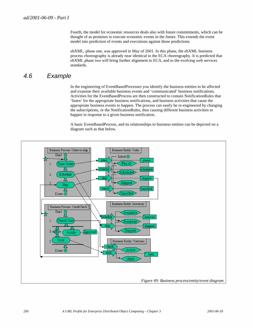
ad/2001-06-09 - Part I
260 A UML Profile for Enterprise Distributed Object Computing – Chapter 3 2001-06-18
Fourth, the model for economic resources deals also with future commitments, which can be thought of as promises to execute economic events in the future. This extends the event model into prediction of events and executions against those predictions.
ebXML, phase one, was approved in May of 2001. In this phase, the ebXML business process choreography is already near identical to the ECA choreography. It is predicted that ebXML phase two will bring further alignment to ECA, and to the evolving web services standards.
4.6 Example
In the engineering of EventBasedProcesses you identify the business entities to be affected and examine their available business events and ‘communicated’ business notifications. Activities for the EventBasedProcess are then constructed to contain NotificationRules that ‘listen’ for the appropriate business notifications, and business activities that cause the appropriate business events to happen. The process can easily be re-engineered by changing the subscriptions, or the NotificationRules, thus causing different business activities to happen in response to a given business notification.
A basic EventBasedProcess, and its relationships to business entities can be depicted on a diagram such as that below.
Figure 49: Business process/entity/event diagram

ad/2001-06-09 - Part I
2001-06-18 A UML Profile for Enterprise Distributed Object Computing – Chapter 3 261
Processes and entities are depicted as large boxes. Activities within a process are ovals. Events are ‘dog-eared’ boxes. Entity operations are fat arrows. Entity states are hexagons. Business notifications are arrows from event boxes to the left side of process boxes. Invocations of entity operations are arrows from activity ovals to the fat arrows.
This diagram contains notational elements that can (almost) all be mapped directly to an Activity Diagram for the EventBasedProcess, a State Chart for the Entity, and a Sequence Diagram for the interaction between the two.
ad/2001-06-09 - Part I
262 A UML Profile for Enterprise Distributed Object Computing – Chapter 3 2001-06-18
5. The Business Processes Profile
The Business Processes profile specializes the CCA, and describes a set of UML extensions that may be used on their own, or in combination with the other EDOC elements, to model system behavior in the context of the business it supports.
5.1 Introduction
The Business Process profile provides modeling concepts that allow the description of business processes in terms of a composition of business activities, selection criteria for the entities that carry out these activities, and their communication and coordination. In particular, the Business Process profile provides the ability to express:
• complex dependencies between individual business tasks (i.e. logical units of work) constituting a business process, as well as rich concurrency semantics;
• representation of several business tasks at one level of abstraction as a single business task at a higher level of abstraction and precisely defining relationships between such tasks, covering activation and termination semantics for these tasks;
• representation of iteration in business tasks;
• various time expressions, such as duration of a task and support for expression of deadlines;
• support for the detection of unexpected occurrences while performing business tasks that need to be acted upon, i.e. exceptional situations;
• associations between the specifications of business tasks and business roles that perform these tasks and also those roles that are needed for task execution;
• initiation of specific tasks in response to the occurrence of business events;
• the exposure of actions that take place during a business process as business events.
5.2 Metamodel
This model is organized with three main model elements to describe a business process: BusinessProcess, CompoundTask and Activityas shown in Figure 50 in which the derivation from the CCA is shown. BusinessProccess is the outermost layer of composition representing a complete process specification. It is a ProcessComponent for the purpose of its usage inside other CCA Compositions, but its Composition is constrainedin the same way as a CompoubdTask.In other words, BusinessProcesses are the entry point from CCAto a process definition. CompoundTasks arealsospecializations of CCA ProcessComponents, but their Ports are constrained specializations of CCA Ports whichrepresent the data required to initiate an enactment itsComposition,which defines how itexecutes. The only ComponentUsages CompoundTasks and BusinessProcesses may contain are Activities, whichare specializations of CCA ComponentUsages. Activities are the pieces of work required to complete a Process, and CompoundTasks are the containers for a logical set of Activities and the DataFlows that define the temporal and data dependencies between them. DataFlows are specializations of CCA Flows that connect the PortConnectors on the Activities. Activities are always usages of a CompoundTask definition, which defines the
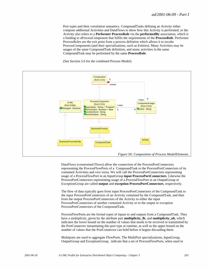
ad/2001-06-09 - Part I
2001-06-18 A UML Profile for Enterprise Distributed Object Computing – Chapter 3 263
Port types and their correlation semantics. CompoundTasks defining an Activity either compose additional Activities and DataFlows to show how this Activity is performed, or the Activity also refers to a Performer ProcessRole via the performedBy association, which is a binding to aProcessComponent that fulfils the requirements of the ProcessRole. Performer ProcessRoles are the exit point from a process defintion which allows it to invoke ProcessComponents (and their specializations, such as Entities). Many Activities may be usages of the same CompoundTask definition, and many activities in the same CompoundTask may be performed by the same ProcessRole.
(See Section 5.6 for the combined Process Model)
Activity
ProcessComponent
granularity : String = "Program"isPersistent : Boolean = falseprimitiveKind : StringprimitiveSpec : String
(from CCA) ComponentUsage
name : String(from CCA)
n1 n
+uses
1
Composition(from CCA)
n
1
+uses n
+owner
1
CompoundTask
BusinessProcess
BusinessProcessEntity
Entity
Managed : Boolean(from Entity)
Figure 50: Composition of Process ModelElements.
DataFlows (constrained Flows) allow the connection of the ProcessPortConnectors representing the ProcessFlowPorts of a CompoundTask to the ProcessPortConnectors of its contained Activities and vice versa. We will call the ProcessPortConnectors representing usage of a ProcessFlowPort in an InputGroup input ProcessPortConnectors. Likewise the ProcessPortConnectors representing usage of a ProcessFlowPort in an OutputGroup or ExceptionGroup are called output and exception ProcessPortConnectors, respectively. The flow of data typically goes from input ProcessPortConnectors of the CompoundTask to the input ProcessPortConnectors of an Activity contained by the CompoundTask, and then from the output ProcessPortConnectors of the Activity to either the input ProcessPortConnectors of another contained Activity or to the output or exception ProcessPortConnectors of the CompoundTask. ProcessFlowPorts are the formal types of inputs to and outputs from a CompoundTask. They have a multiplicity, given by the attribute pair multiplicity_lb, and multiplicity_ub, which indicates the lower bound on the number of values that needs to be received or transmitted by the PortConnector instantiating this port type at runtime, as well as the upper bound on the number of values that the PortConnector can hold before it begins discarding them. Multiports are used to aggregate FlowPorts. The MultiPort specializations, InputGroup, OutputGroup and ExceptionGroup, indicate that a set of ProcessFlowPorts, when used in
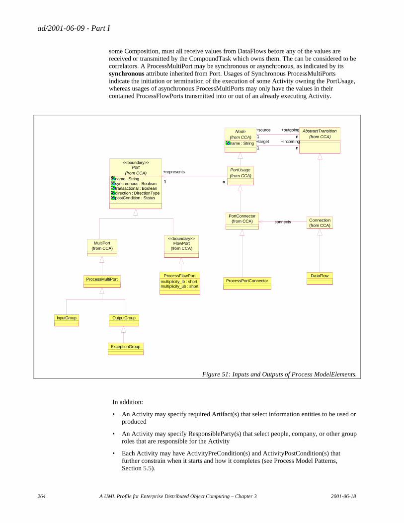
ad/2001-06-09 - Part I
264 A UML Profile for Enterprise Distributed Object Computing – Chapter 3 2001-06-18
some Composition, must all receive values from DataFlows before any of the values are received or transmitted by the CompoundTask which owns them. The can be considered to be correlators. A ProcessMultiPort may be synchronous or asynchronous, as indicated by its synchronous attribute inherited from Port. Usages of Synchronous ProcessMultiPorts indicate the initiation or termination of the execution of some Activity owning the PortUsage, whereas usages of asynchronous ProcessMultiPorts may only have the values in their contained ProcessFlowPorts transmitted into or out of an already executing Activity.
Port
name : Stringsynchronous : Booleantransactional : Booleandirection : DirectionTypepostCondition : Status
(from CCA)
<<boundary>>
PortUsage(from CCA)
1 n
+represents
1 n
PortConnector(from CCA)
AbstractTransition(from CCA)
Node
name : String
(from CCA) n1
+outgoing
n
+source
1
n1
+incoming
n
+target
1
FlowPort(from CCA)
<<boundary>>MultiPort
(from CCA)
ProcessMultiPort
InputGroup OutputGroup
ExceptionGroup
ProcessFlowPortmultiplicity_lb : shortmultiplicity_ub : short
ProcessPortConnectorDataFlow
Connection(from CCA)
connects
Figure 51: Inputs and Outputs of Process ModelElements.
In addition:
• An Activity may specify required Artifact(s) that select information entities to be used or produced
• An Activity may specify ResponsibleParty(s) that select people, company, or other group roles that are responsible for the Activity
• Each Activity may have ActivityPreCondition(s) and ActivityPostCondition(s) that further constrain when it starts and how it completes (see Process Model Patterns, Section 5.5).

ad/2001-06-09 - Part I
2001-06-18 A UML Profile for Enterprise Distributed Object Computing – Chapter 3 265
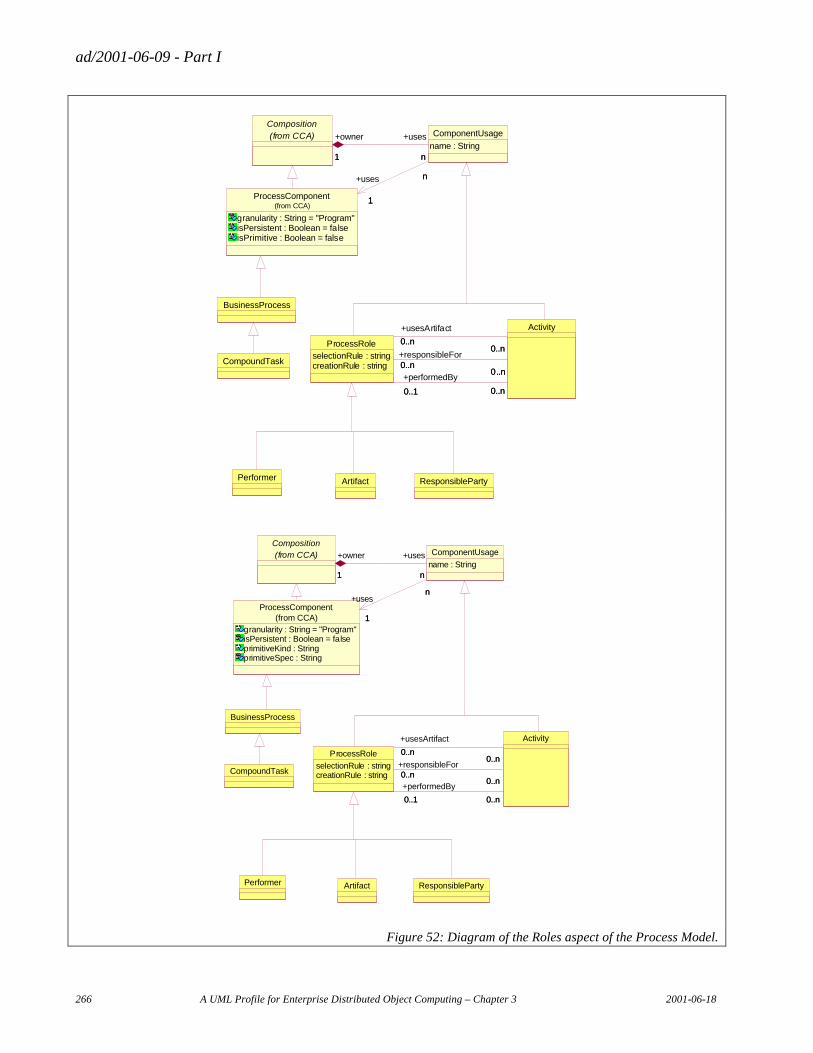
ad/2001-06-09 - Part I
266 A UML Profile for Enterprise Distributed Object Computing – Chapter 3 2001-06-18
Composition(from CCA)
Performer Artifact ResponsibleParty
Activity
ProcessRoleselectionRule : stringcreationRule : string 0..n
0..n
+responsibleFor0..n
0..n
0..n0..n
+usesArtifact
0..n0..n
+performedBy
0..1 0..n0..1 0..n
CompoundTask
BusinessProcess
ProcessComponent
granularity : String = "Program"isPersistent : Boolean = falseisPrimitive : Boolean = false
(from CCA)
ComponentUsage
name : Stringn1
+uses
n
+owner
1
+uses n
1
n
1
Performer Artifact ResponsibleParty
ProcessRole
selectionRule : stringcreationRule : string
Activity
0..n0..n
+responsibleFor0..n
0..n
0..n0..n
+usesArtifact
0..n0..n
0..1 0..n
+performedBy
0..1 0..n
CompoundTask
BusinessProcess
Composition(from CCA) ComponentUsage
name : Stringn1
+uses
n
+owner
1
ProcessComponent
granularity : String = "Program"isPersistent : Boolean = falseprimitiveKind : StringprimitiveSpec : String
(from CCA)
n
1
n+uses
1
Figure 52: Diagram of the Roles aspect of the Process Model.
ad/2001-06-09 - Part I
2001-06-18 A UML Profile for Enterprise Distributed Object Computing – Chapter 3 267
The model in Figure 52 shows the ownership of ProcessRoles by CompoundTasks (via their ProcessComponent base class). ProcessRoles have three kinds of relationships with Activities. An Activity may be performedBy a ProcessRole, or it is possible that an Activity has a usesArtifact association with a ProcessRole, or a ProcessRole may be responsible for an Activity, as indicated by a responsibleFor association end role. The same ProcessRole may have several associations with different Activities, for example to be the performer for one activity, while also being an artifact for another, or to be both the responsible party and performer for an Activity. The specific ProcessRoles of Performer, Artifact and ResponsibleParty are constrained to be associated with Activities only by the performedBy, usesArtifact and responsibleFor associations respectively, and are useful in many cases where ProcessRoles do not need to be re-used.
At run time a ProcessRole represents the binding of a state variable in its owner CompoundTask to a concrete ProcessComponent instance that meets the requirements of the selectionRule or creationRule attributes of the ProcessRole. Typically the performer roles of an Activity will have a type from which the defining CompoundTask of that Activity have been derived. The OperationPorts of the ProcessComponent identified by the ProcessRole will be represented as a pair of an InputGroup and an OutputGroup that contain ProcessFlowPorts that represent the input and output parameters of the OperationPort. Exceptions are represented by additional ExceptionGroups.
In addition to the basic set of model elements given above, there are a number of other important concepts required in the modeling of Processes that can be expressed as patterns of use of these basic elements:
• ActivityPreCondition
• ActivityPostCondition
• Timeout
• Terminate
• Loops
− Simple Loop
− While and Repeat/Until Loop
− For Loop
• Multitask
These are explained in Section 5.5 “Process Model Patterns”.
An example of a CompoundTask containing Activities is shown in Figure 53.
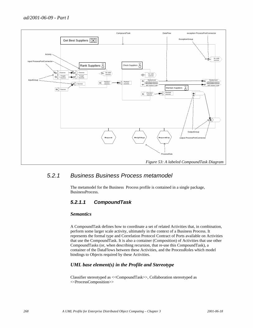
ad/2001-06-09 - Part I
268 A UML Profile for Enterprise Distributed Object Computing – Chapter 3 2001-06-18
Re q u e stG rpWe ightin g sRe q u e st
Get Best Suppliers
Check SuppliersRank Suppliers
SourcesMaintain Suppliers
Sources
Sources
FreightSources
No validsources
Rankedsources
Checkedsources
Discarded sourceswith reasion code
Ranked andprioritised sources
Checkedsources
Discarded sourceswith reasion code
Ranked andprioritised sourcesRanked
sources
No validsources
No validsources
Sources
FreightSources
Activity
CompoundTask
input ProcessPortConnector
output ProcessPortConnector
exception ProcessPortConnectorDataFlow
InputGroup
OutputGroup
ExceptionGroup
ProcessRole
Figure 53: A labeled CompoundTask Diagram
5.2.1 Business Business Process metamodel
The metamodel for the Business Process profile is contained in a single package, BusinessProcess.
5.2.1.1 CompoundTask
Semantics
A CompoundTask defines how to coordinate a set of related Activities that, in combination, perform some larger scale activity, ultimately in the context of a Business Process. It represents the formal type and Correlation Protocol Contract of Ports available on Activities that use the CompoundTask. It is also a container (Composition) of Activities that use other CompoundTasks (or, when describing recursion, that re-use this CompoundTask), a container of the DataFlows between these Activities, and the ProcessRoles which model bindings to Objects required by these Activities.
UML base element(s) in the Profile and Stereotype
Classifier stereotyped as <<CompoundTask>>, Collaboration stereotyped as <<ProcessComposition>>
ad/2001-06-09 - Part I
2001-06-18 A UML Profile for Enterprise Distributed Object Computing – Chapter 3 269
Fully Scoped name
ECA::BusinessProcess::CompoundTask
Owned by
Inheritance
ECA::BusinessProcess::BusinessProcess CompoundTask
Properties
Associated elements
Constraints
[1] All Ports owned by a CompoundTask must be ProcessMultiPorts.
[2] All ComponentUsages contained by a CompoundTask must be Activities.
[3] All PortUsages directly contained by a CompoundTask must represent ProcessMultiPorts owned by the CompoundTask.
5.2.1.2 Activity
Semantics
Activity represents the execution of a part of a Business Process using one of two mechanisms (but not both). The mechanisms are:
• The creation of a Composition of nested Activities, ProcessRoles and DataFlows described by the CompoundTask that the Activity references through its uses association.
• The execution of some feature of an Object bound to a ProcessRole instance referred to via the Activity’s performedBy association. (See “ProcessRole” on page 283.)
Hence an Activity represents an action that is either described by a further decomposition in the form of a CompoundTask or it represents and action that is performed by objects bound to ProcessRoles either statically, or at runtime as the Activity enters the Running state.
An Activity may also be associated via the usesArtifact and responsibleFor associations to one or more ProcessRoles. These ProcessRoles will be bound to Objects at run time as the Activity enters the Running state.
An Activity’s PortUsages representing InputGroups (input PortUsages), which contain ProcessPortConnectors representing ProcessFlowPorts (input ProcessPortConnectors), are the alternative means by which the Activity may supply data to these mechanisms to initiate some action.
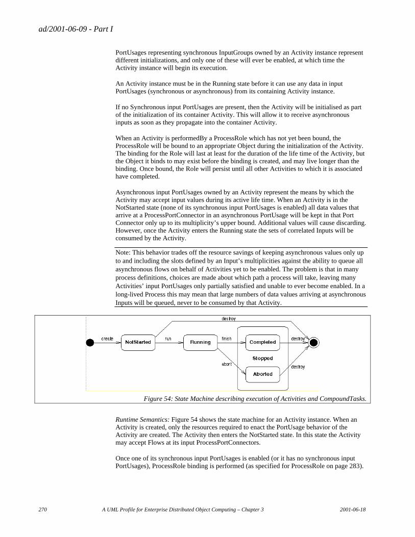
ad/2001-06-09 - Part I
270 A UML Profile for Enterprise Distributed Object Computing – Chapter 3 2001-06-18
PortUsages representing synchronous InputGroups owned by an Activity instance represent different initializations, and only one of these will ever be enabled, at which time the Activity instance will begin its execution.
An Activity instance must be in the Running state before it can use any data in input PortUsages (synchronous or asynchronous) from its containing Activity instance.
If no Synchronous input PortUsages are present, then the Activity will be initialised as part of the initialization of its container Activity. This will allow it to receive asynchronous inputs as soon as they propagate into the container Activity.
When an Activity is performedBy a ProcessRole which has not yet been bound, the ProcessRole will be bound to an appropriate Object during the initialization of the Activity. The binding for the Role will last at least for the duration of the life time of the Activity, but the Object it binds to may exist before the binding is created, and may live longer than the binding. Once bound, the Role will persist until all other Activities to which it is associated have completed.
Asynchronous input PortUsages owned by an Activity represent the means by which the Activity may accept input values during its active life time. When an Activity is in the NotStarted state (none of its synchronous input PortUsages is enabled) all data values that arrive at a ProcessPortConnector in an asynchronous PortUsage will be kept in that Port Connector only up to its multiplicity’s upper bound. Additional values will cause discarding. However, once the Activity enters the Running state the sets of correlated Inputs will be consumed by the Activity.
Note: This behavior trades off the resource savings of keeping asynchronous values only up to and including the slots defined by an Input’s multiplicities against the ability to queue all asynchronous flows on behalf of Activities yet to be enabled. The problem is that in many process definitions, choices are made about which path a process will take, leaving many Activities’ input PortUsages only partially satisfied and unable to ever become enabled. In a long-lived Process this may mean that large numbers of data values arriving at asynchronous Inputs will be queued, never to be consumed by that Activity.
Figure 54: State Machine describing execution of Activities and CompoundTasks.
Runtime Semantics: Figure 54 shows the state machine for an Activity instance. When an Activity is created, only the resources required to enact the PortUsage behavior of the Activity are created. The Activity then enters the NotStarted state. In this state the Activity may accept Flows at its input ProcessPortConnectors.
Once one of its synchronous input PortUsages is enabled (or it has no synchronous input PortUsages), ProcessRole binding is performed (as specified for ProcessRole on page 283).
ad/2001-06-09 - Part I
2001-06-18 A UML Profile for Enterprise Distributed Object Computing – Chapter 3 271
Then, if the Activity uses a CompoundTask that is a non-empty Composition, all the resources to represent the contained DataFlows, Bindings and nested Activities are allocated and all nested Activities are created. The Activity now enters the Running state.
An Activity instance enters the Completed state when none of its contained Activity instances that have synchronous output PortUsages containing values (that are not also exception PortUsages) are in the Running state and there are no DataFlows that are in the process of delivering their data (which could then trigger the running of another Activity). Note, this means that not all contained Activities need to have executed, only that none (that have synchronous output ProcessMultiPorts) are running. This results in a quiescent model for completion.
Alternatively, if an Activity instance has an exception PortUsage that is satisfied, then all Activity instances that are contained by this Activity instance and are in the Running state are aborted. The Activity will then satisfy the quiescent model completion criteria just outlined.
An Activity instance enters the Completed state, if a satisfied synchronous output PortUsage is enabled. If there is more than one satisfied synchronous output PortUsage, then the choice of which one to enable is arbitrary. If there is no synchronous output PortUsage that is satisfied, then the Activity instance’s system ExceptionGroup is enabled.
If a nested Activity instance contained by an Activity enters the Completed state with an exception PortUsage enabled and the exception is unhandled (see Section 5.2.1.11 “ExceptionGroup” for the definition of handled and unhandled ExceptionGroups), then the containing Activity instance’s system ExceptionGroup is enabled.
If an Activity instance is aborted, it terminates all of its contained Activity instances and enters the Aborted state.
If the Activity uses an empty Composition it must have a performedBy link to a ProcessRole, which will now be bound, and the Activity instance enters the Running state. While in the Running state, values from enabled input ProcessPortConnector instances may be consumed. In most cases this will mean that the PortUsage that was enabled has a collection of input Parameters for a method on the Object bound to the performer ProcessRole, which will be invoked. The return of the method will place values into an output PortUsage (representing an OutputGroup or ExceptionGroup), which will enable that PortUsage.
The Activity instance enters the Stopped state when one of its synchronous OutputGroup instances is enabled. If this is an ExceptionGroup instance, then it enters the Aborted state, otherwise it enters the Completed state.
UML base element(s) in the Profile and Stereotype
ClassifierRole stereotyped as <<Activity>>
Fully Scoped name
ECA::BusinessProcess::Activity
Owned by
CompoundTask
ad/2001-06-09 - Part I
272 A UML Profile for Enterprise Distributed Object Computing – Chapter 3 2001-06-18
Inheritance
ECA::CCA:: ComponentUsage Activity
Properties
Associated elements
uses (from ComponentUsage)
An Activity is always associated with a CompoundTask via the uses association
performedBy
An Activity with an empty CompoundTask Composition must be linked to a single ProcessRole via the performedBy association.
usesArtifact
An Activity may require access to Objects via a ProcessRole to use as a passive resource. Its usesArtifact association indicates the Roles it uses for this purpose.
responsibleFor
An Activity in a BusinessProcess may be perfomedBy a ProcessRole that does so on behalf of another Role or Roles that are responsible for the Activity. The responsibleFor association allows these Roles to identify Object representing responsible parties.
Constraints
[1] An Activity that uses a CompoundTask definition with no internal Composition must have a performedBy link.
5.2.1.3 BusinessProcess
Semantics
A BusinessProcess defines the ProcessComponent view of a process definition that coordinates a set of related Activities. It defines a complete business process which can be invoked from another CCA Composition, usually using OperationPorts which are connected via DataFlows (a subtype of CCA Flow) to the ProcessPortConnectors of the Activities which it contains. In other words a BusinessProcess is an ordinary ProcessComponent on the outside, and a CompoundTask on the inside.
UML base element(s) in the Profile and Stereotype
Classifier stereotyped as <<BusinessProcess>>
ad/2001-06-09 - Part I
2001-06-18 A UML Profile for Enterprise Distributed Object Computing – Chapter 3 273
Fully Scoped name
ECA::BusinessProcess::BusinessProcess
Owned by
Inheritance
ECA::CCA::ComponentDefintion::ProcessComponent BusinessProcess
Properties
Associated elements
Constraints
All ComponentUsages contained by a BusinessProcess must be Activities.
All Connectors contained by a BusinessProcess must be DataFlows.
5.2.1.4 BusinessProcessEntity
Semantics
A BusinessProcessEntity is a BusinessProcess that is also an Entity with identity. It is used to model long-lived processes that may require management and or interaction during their lifetime.
UML base element(s) in the Profile and Stereotype
ClassifierRole stereotyped as <<BusinessProcessEntity>>
Fully Scoped name
ECA::BusinessProcess::BusinessProcessEntity
Owned by
Inheritance
ECA::BusinessProcess::BusinessProcess BusinessProcessEntity ECA::Entity::Entity BusinessProcessEntity
ad/2001-06-09 - Part I
274 A UML Profile for Enterprise Distributed Object Computing – Chapter 3 2001-06-18
Properties
Associated elements
Constraints
N/A
5.2.1.5 ProcessFlowPort
Semantics
ProcessFlowPort represents data used in CompoundTask input/output.
Runtime Semantics: A ProcessFlowPort instance (represented by a ProcessPortConnector on an Activity) is satisfied when it has at least multiplicity_lb values, otherwise it is unsatisfied. It may not have more than multiplicity_ub values.
If a ProcessFlowPort instance is the sink of more than one DataFlow, then data values for that instance can be supplied by any one of those DataFlows up to the upper bound its multiplicity. In the default case of a multiplicity of {1,1} this implies OR semantics. If more values are supplied than the multiplicity’s upper bound, the ProcessFlowPort instance’s collection remains at the size of the upper bound, and some arbitrary set of values are discarded.
When a ProcessFlowPort instance is enabled and its containing CompoundTask instance (represented by an Activity) is in the Running state, it transmits its values using all the associated DataFlows (AND semantics) as appropriate. If the ProcessFlowPort instance is contained by an asynchronous InputGroup instance, it then discards its values and resets its state to unsatisfied or satisfied according to its multiplicity.
UML base element(s) in the Profile and Stereotype
Class stereotyped as <<ProcessFlowPort>>
Fully Scoped name
ECA::BusinessProcess::ProcessFlowPort
Owned by
ProcessMultiPort
Inheritance
ECA::CCA::FlowPort ProcessFlowPort
Properties
ad/2001-06-09 - Part I
2001-06-18 A UML Profile for Enterprise Distributed Object Computing – Chapter 3 275
multiplicity_lb : short
multiplicity_ub : short
The multiplicity of a ProcessFlowPort instance allows it to act as a collection of data values of the same type. A multiplicity is expressed as a lower-bound, upper-bound pair {multiplicity_lb, multiplicity_ub}, where -1 is used in the upper bound to indicate infinity. The default multiplicity is {1,1} which represents a singleton collection.
Associated elements
ECA::CCA::DocumentModel::DataElement
A ProcessFlowPort is optionally associated with a DataElement by the type association, which is inherited from FlowPort. A ProcessFlowPort that does not have an associated type can be thought of as a control point. That is, the values handled by these ProcessFlowPorts are like objects that have identity but no attributes. They can be used, in conjunction with DataFlows, to describe control flow constraints that do not involve data values.
Constraints
[1] A ProcessFlowPort must be owned by a ProcessMultiPort.
5.2.1.6 ProcessPortConnector
Semantics
A ProcessPortConnector represents the usage of a ProcessFlowPort in the context of a CompoundTask.
UML base element(s) in the Profile and Stereotype
ClassifierRole stereotyped as <<ProcessPortConnector>>
Fully Scoped name
ECA::BusinessProcess::ProcessPortConnector
Owned by
CompoundTask
Inheritance
ECA::CCA::ComponentDefinition::PortConnector ProcessPortConnector
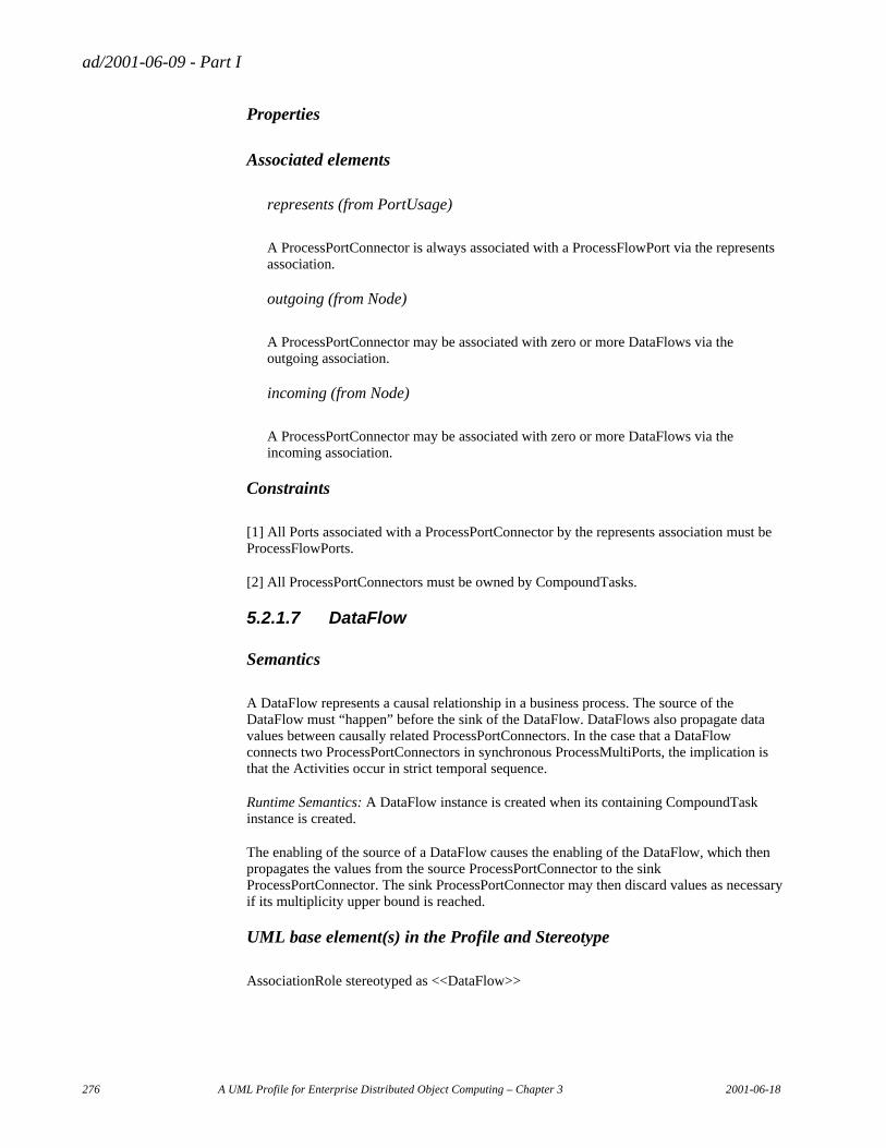
ad/2001-06-09 - Part I
276 A UML Profile for Enterprise Distributed Object Computing – Chapter 3 2001-06-18
Properties
Associated elements
represents (from PortUsage)
A ProcessPortConnector is always associated with a ProcessFlowPort via the represents association.
outgoing (from Node)
A ProcessPortConnector may be associated with zero or more DataFlows via the outgoing association.
incoming (from Node)
A ProcessPortConnector may be associated with zero or more DataFlows via the incoming association.
Constraints
[1] All Ports associated with a ProcessPortConnector by the represents association must be ProcessFlowPorts.
[2] All ProcessPortConnectors must be owned by CompoundTasks.
5.2.1.7 DataFlow
Semantics
A DataFlow represents a causal relationship in a business process. The source of the DataFlow must “happen” before the sink of the DataFlow. DataFlows also propagate data values between causally related ProcessPortConnectors. In the case that a DataFlow connects two ProcessPortConnectors in synchronous ProcessMultiPorts, the implication is that the Activities occur in strict temporal sequence.
Runtime Semantics: A DataFlow instance is created when its containing CompoundTask instance is created.
The enabling of the source of a DataFlow causes the enabling of the DataFlow, which then propagates the values from the source ProcessPortConnector to the sink ProcessPortConnector. The sink ProcessPortConnector may then discard values as necessary if its multiplicity upper bound is reached.
UML base element(s) in the Profile and Stereotype
AssociationRole stereotyped as <<DataFlow>>
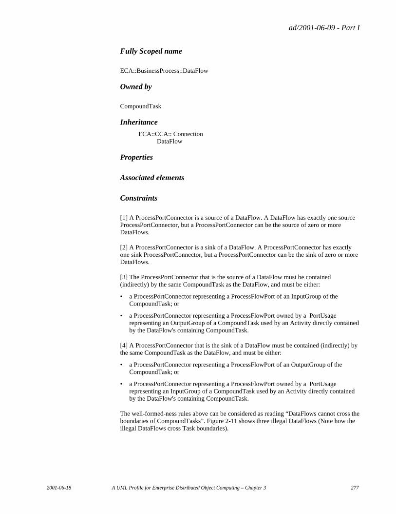
ad/2001-06-09 - Part I
2001-06-18 A UML Profile for Enterprise Distributed Object Computing – Chapter 3 277
Fully Scoped name
ECA::BusinessProcess::DataFlow
Owned by
CompoundTask
Inheritance
ECA::CCA:: Connection DataFlow
Properties
Associated elements
Constraints
[1] A ProcessPortConnector is a source of a DataFlow. A DataFlow has exactly one source ProcessPortConnector, but a ProcessPortConnector can be the source of zero or more DataFlows.
[2] A ProcessPortConnector is a sink of a DataFlow. A ProcessPortConnector has exactly one sink ProcessPortConnector, but a ProcessPortConnector can be the sink of zero or more DataFlows.
[3] The ProcessPortConnector that is the source of a DataFlow must be contained (indirectly) by the same CompoundTask as the DataFlow, and must be either:
• a ProcessPortConnector representing a ProcessFlowPort of an InputGroup of the CompoundTask; or
• a ProcessPortConnector representing a ProcessFlowPort owned by a PortUsage representing an OutputGroup of a CompoundTask used by an Activity directly contained by the DataFlow's containing CompoundTask.
[4] A ProcessPortConnector that is the sink of a DataFlow must be contained (indirectly) by the same CompoundTask as the DataFlow, and must be either:
• a ProcessPortConnector representing a ProcessFlowPort of an OutputGroup of the CompoundTask; or
• a ProcessPortConnector representing a ProcessFlowPort owned by a PortUsage representing an InputGroup of a CompoundTask used by an Activity directly contained by the DataFlow's containing CompoundTask.
The well-formed-ness rules above can be considered as reading “DataFlows cannot cross the boundaries of CompoundTasks”. Figure 2-11 shows three illegal DataFlows (Note how the illegal DataFlows cross Task boundaries).
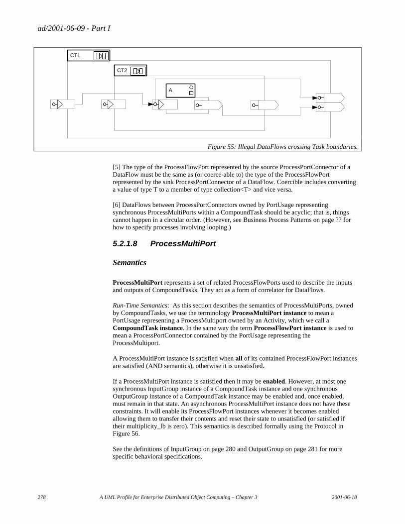
ad/2001-06-09 - Part I
278 A UML Profile for Enterprise Distributed Object Computing – Chapter 3 2001-06-18
CT2
A
CT1
Figure 55: Illegal DataFlows crossing Task boundaries.
[5] The type of the ProcessFlowPort represented by the source ProcessPortConnector of a DataFlow must be the same as (or coerce-able to) the type of the ProcessFlowPort represented by the sink ProcessPortConnector of a DataFlow. Coercible includes converting a value of type T to a member of type collection<T> and vice versa.
[6] DataFlows between ProcessPortConnectors owned by PortUsage representing synchronous ProcessMultiPorts within a CompoundTask should be acyclic; that is, things cannot happen in a circular order. (However, see Business Process Patterns on page ?? for how to specify processes involving looping.)
5.2.1.8 ProcessMultiPort
Semantics
ProcessMultiPort represents a set of related ProcessFlowPorts used to describe the inputs and outputs of CompoundTasks. They act as a form of correlator for DataFlows.
Run-Time Semantics: As this section describes the semantics of ProcessMultiPorts, owned by CompoundTasks, we use the terminology ProcessMultiPort instance to mean a PortUsage representing a ProcessMultiport owned by an Activity, which we call a CompoundTask instance. In the same way the term ProcessFlowPort instance is used to mean a ProcessPortConnector contained by the PortUsage representing the ProcessMultiport.
A ProcessMultiPort instance is satisfied when all of its contained ProcessFlowPort instances are satisfied (AND semantics), otherwise it is unsatisfied.
If a ProcessMultiPort instance is satisfied then it may be enabled. However, at most one synchronous InputGroup instance of a CompoundTask instance and one synchronous OutputGroup instance of a CompoundTask instance may be enabled and, once enabled, must remain in that state. An asynchronous ProcessMultiPort instance does not have these constraints. It will enable its ProcessFlowPort instances whenever it becomes enabled allowing them to transfer their contents and reset their state to unsatisfied (or satisfied if their multiplicity_lb is zero). This semantics is described formally using the Protocol in Figure 56.
See the definitions of InputGroup on page 280 and OutputGroup on page 281 for more specific behavioral specifications.
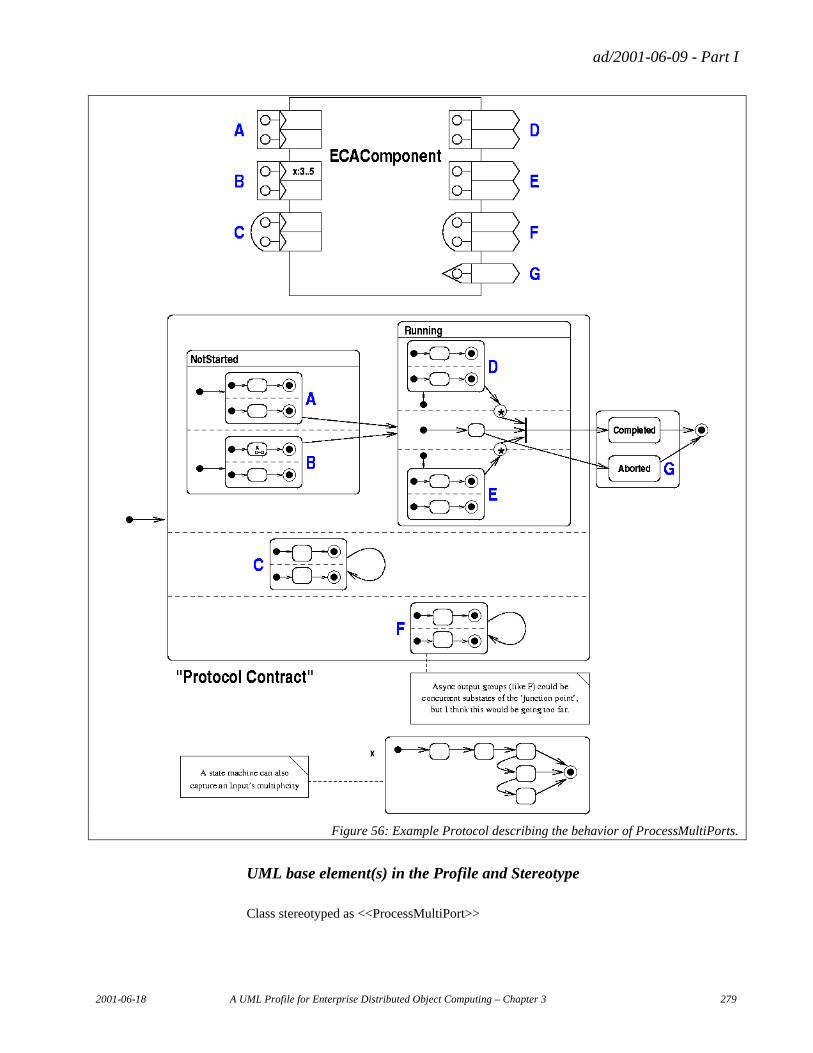
ad/2001-06-09 - Part I
2001-06-18 A UML Profile for Enterprise Distributed Object Computing – Chapter 3 279
Figure 56: Example Protocol describing the behavior of ProcessMultiPorts.
UML base element(s) in the Profile and Stereotype
Class stereotyped as <<ProcessMultiPort>>
ad/2001-06-09 - Part I
280 A UML Profile for Enterprise Distributed Object Computing – Chapter 3 2001-06-18
Fully Scoped name
ECA::BusinessProcess::ProcessMultiPort
Owned by
CompoundTask
Inheritance
ECA::CCA::MultiPort ProcessMultiPort
Properties
synchronous : boolean (from Port)
A value of TRUE indicates that this ProcessMultiPort represents either parameters that may be used to trigger a CompoundTask instance to enter the Running state, or results that are available when the instance enters the Stopped state.
A value of FALSE indicates that while the CompoundTask instance is in the Running state, the ProcessMultiPort may either asynchronously consume one or more sets of data, or asynchronously emit one or more sets of data.
Associated elements
ProcessFlowPort
A ProcessMultiPort provides a correlation framework for a number of ProcessFlowPorts.
Constraints
[1] The Composition owning a ProcessMultiPort must be a CompoundTask.
5.2.1.9 InputGroup
Semantics
InputGroup is a specialization of ProcessMultiPort. It is a container for a number of ProcessFlowPorts which are the inputs to a CompoundTask.
Runtime Semantics: The InputGroup implies special semantics for the lifecycle of an Activity using the CompoundTask defintition that owns it when its synchronous attribute is TRUE. In this case the InputGroup must be enabled before the Activity may enter its Running state.
ad/2001-06-09 - Part I
2001-06-18 A UML Profile for Enterprise Distributed Object Computing – Chapter 3 281
UML base element(s) in the Profile and Stereotype
Class stereotyped as <<InputGroup>>
Fully Scoped name
ECA::BusinessProcess::InputGroup
Owned by
CompoundTask (via its base class Composition)
Inheritance
ECA::CCA::ComponentSpecification::ProcessMultiPort InputGroup
Properties
Associated elements
Constraints
5.2.1.10 OutputGroup
Semantics
OutputGroup represents a possible outcome of a CompoundTask; it provides data values associated with that outcome. In the case of a synchronous OutputGroup it also serves as an indication that an Activity using the CompoundTask defintion to which the OutputGroup belongs has entered the Stopped state.
OutputGroup models a collection of data values produced by a CompoundTask.
Runtime Semantics: The OutputGroup implies special semantics for the lifecycle of an Activity using the CompoundTask definition which owns it when its synchronous attribute is TRUE. In this case the Activity must be in its Stopped state before the OutputGroup may be enabled.
UML base element(s) in the Profile and Stereotype
Class stereotyped as <<OutputGroup>>
Fully Scoped name
ECA::BusinessProcess::OutputGroup
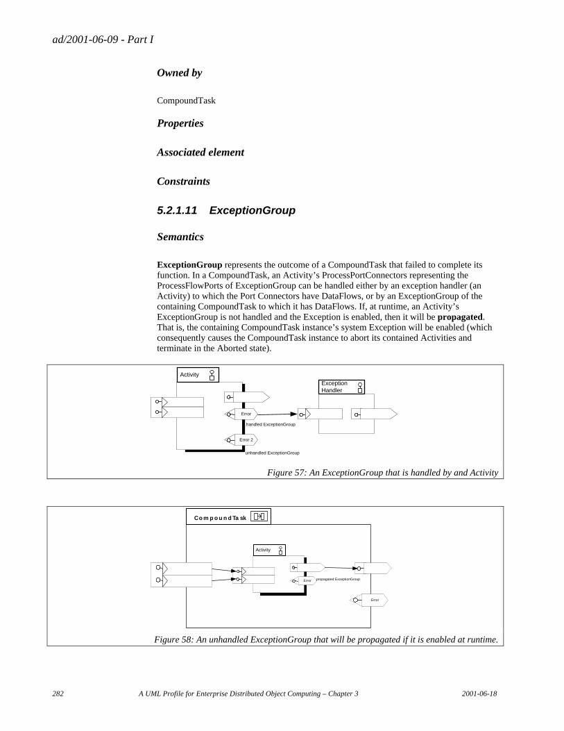
ad/2001-06-09 - Part I
282 A UML Profile for Enterprise Distributed Object Computing – Chapter 3 2001-06-18
Owned by
CompoundTask
Properties
Associated element
Constraints
5.2.1.11 ExceptionGroup
Semantics
ExceptionGroup represents the outcome of a CompoundTask that failed to complete its function. In a CompoundTask, an Activity’s ProcessPortConnectors representing the ProcessFlowPorts of ExceptionGroup can be handled either by an exception handler (an Activity) to which the Port Connectors have DataFlows, or by an ExceptionGroup of the containing CompoundTask to which it has DataFlows. If, at runtime, an Activity’s ExceptionGroup is not handled and the Exception is enabled, then it will be propagated. That is, the containing CompoundTask instance’s system Exception will be enabled (which consequently causes the CompoundTask instance to abort its contained Activities and terminate in the Aborted state).
Activity
Error
ExceptionHandler
Error 2
handled ExceptionGroup
unhandled ExceptionGroup
Figure 57: An ExceptionGroup that is handled by and Activity
Activity
Error propagated ExceptionGroup
C o m p o u n d Ta sk
Error
Figure 58: An unhandled ExceptionGroup that will be propagated if it is enabled at runtime.
ad/2001-06-09 - Part I
2001-06-18 A UML Profile for Enterprise Distributed Object Computing – Chapter 3 283
UML base element(s) in the Profile and Stereotype
Class stereotyped as <<ExceptionGroup>>
Fully Scoped name
ECA::BusinessProcess::ExceptionGroup
Owned by
CompoundTask
Properties
Associated elements
Constraints
5.2.1.12 ProcessRole
Semantics
ProcessRole defines a placeholder for concrete ProcessComponents that perform an Activity or that are used in the performing of an Activity. It defines a placeholder for behavior in a context. ProcessRole is a subtype of ComponentUsage with some qualifying attributes. The owner of a ProcessRole is a CompoundTask and the behavior of the ProcessRole becomes part of the behavior of Activities to which it is associated. The uses association of a ProcessRole (inherited from ComponentUsage) defines the type of ProcessComponent that is required to be bound to the placeholder.
Runtime Semantics: When an Activity is enabled, binding of any associated unbound ProcessRole instances ensues based on the values of the selectionRule and creationRule expressions. Note that some ProcessRole instances may have been bound previously due to an association with another Activity that has already been enabled so no further binding is needed.
If both the selectionRule and creationRule expressions are empty, then it is left up to the Activity itself to perform binding. Otherwise, binding takes place as follows:
Binding of an unbound ProcessRole begins by determining the candidate instances. These are the set of ProcessComponent instances with a compatible type and that satisfy the selectionRule. The selectionRule may refer to the values of the input ProcessPortConnectors of any of the ProcessRole's associated Activities. It is incumbent on the modeler to ensure that the selectionRule is well-formed in the face of attributes that may not yet have values.
If there are no candidate instances, and the creationRule expression is non-empty, it will be used to generate a new candidate instance (or instances if the expression returns multiples).
ad/2001-06-09 - Part I
284 A UML Profile for Enterprise Distributed Object Computing – Chapter 3 2001-06-18
One of the candidate instances will then be bound to the ProcessRole. If there are no candidate instances, the containing Activity instance will have its system ExceptionGroup enabled.
We note that something akin to the OMG Trader service can be used for this binding process. Also, the bound entity may be a proxy for a person such as a worklist in a workflow execution environment.
Inheritance
ECA::CCA::ComponentUsage ProcessRole
UML base element(s) in the Profile and Stereotype
ClassifierRole stereotyped as <<ProcessRole>>
Fully Scoped name
ECA::BusinessProcess::ProcessRole
Owned by
CompoundTask
Properties
selectionRule
an expression describing the set of entities that may be bound to this ProcessRole.
creationRule
an expression describing how to create a new entity that may be bound to this ProcessRole.
Associated elements
ProcessComponent: the uses association, inherited from ComponentUsage, indicates a type of ProcessComponent (an abstract ProcessComponent). A concrete instance of this type must be bound to the ProcessRole at runtime.
Activity: these may be associated with ProcessRoles by one or more of the following: performedBy and/or usesArtifact and/or responsibleFor.
Constraints
[1] The ProcessComponent at the opposite end of the uses association must be abstract.
ad/2001-06-09 - Part I
2001-06-18 A UML Profile for Enterprise Distributed Object Computing – Chapter 3 285
5.2.1.13 Performer
Semantics
A Performer ProcessRole is specifically for identifying an Entity that can perform the Activity to which it is associated.
Inheritance
ECA::CCA::ComponentUsage ProcessRole Performer
UML base element(s) in the Profile and Stereotype
ClassifierRole stereotyped as <<Performer>>
Fully Scoped name
ECA::BusinessProcess::Performer
Owned by
CompoundTask
Properties
Associated elements
Activity: these may be associated with Performers by a performedBy association.
Constraints
[1] A Performer may only be associated with Activities using the performedBy association.
5.2.1.14 Artifact
Semantics
A Performer ProcessRole is specifically for identifying an Entity that is needed by an Activity as a resource.
Inheritance
ECA::CCA::ComponentUsage ProcessRole Artifact
ad/2001-06-09 - Part I
286 A UML Profile for Enterprise Distributed Object Computing – Chapter 3 2001-06-18
UML base element(s) in the Profile and Stereotype
ClassifierRole stereotyped as <<Artifact>>
Fully Scoped name
ECA::BusinessProcess::Artifact
Owned by
CompoundTask
Properties
Associated elements
Activity: these may be associated with Artifact by a usesArtifact association.
Constraints
[1] An Artifact may only be associated with Activities using the usesArtifact association.
5.2.1.15 ResponsibleParty
Semantics
A ResponsibleParty ProcessRole is specifically for identifying an Entity that has responsibility for the Activity to which it is associated.
Inheritance
ECA::CCA::ComponentUsage ProcessRole ResponsibleParty
UML base element(s) in the Profile and Stereotype
ClassifierRole stereotyped as <<ResponsibleParty>>
Fully Scoped name
ECA::BusinessProcess::ResponsibleParty
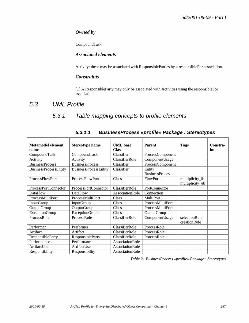
ad/2001-06-09 - Part I
2001-06-18 A UML Profile for Enterprise Distributed Object Computing – Chapter 3 287
Owned by
CompoundTask
Associated elements
Activity: these may be associated with ResponsibleParties by a responsibleFor association.
Constraints
[1] A ResponsibleParty may only be associated with Activities using the responsibleFor association.
5.3 UML Profile
5.3.1 Table mapping concepts to profile elements
5.3.1.1 BusinessProcess «profile» Package : Stereotypes
Metamodel element name
Stereotype name UML base Class
Parent Tags Constra-ints
CompoundTask CompoundTask Classifier ProcessComponent Activity Activity ClassifierRole ComponentUsage BusinessProcess BusinessProcess Classifier ProcessComponent BusinessProcessEntity BusinessProcessEntity Classifier Entity
BusinessProcess
ProcessFlowPort ProcessFlowPort Class FlowPort multiplicity_lb multiplicity_ub
ProcessPortConnector ProcessPortConnector ClassifierRole PortConnector DataFlow DataFlow AssociationRole Connection ProcessMultiPort ProcessMultiPort Class MultiPort InputGroup InputGroup Class ProcessMultiPort OutputGroup OutputGroup Class ProcessMultiPort ExceptionGroup ExceptionGroup Class OutputGroup ProcessRole ProcessRole ClassifierRole ComponentUsage selectionRule
creationRule
Performer Performer ClassifierRole ProcessRole Artifact Artifact ClassifierRole ProcessRole ResponsibleParty ResponsibleParty ClassifierRole ProcessRole Performance Performance AssociationRole ArtifactUse ArtifactUse AssociationRole Responsibility Responsibility AssociationRole
Table 21 BusinessProcess «profile» Package : Stereotypes
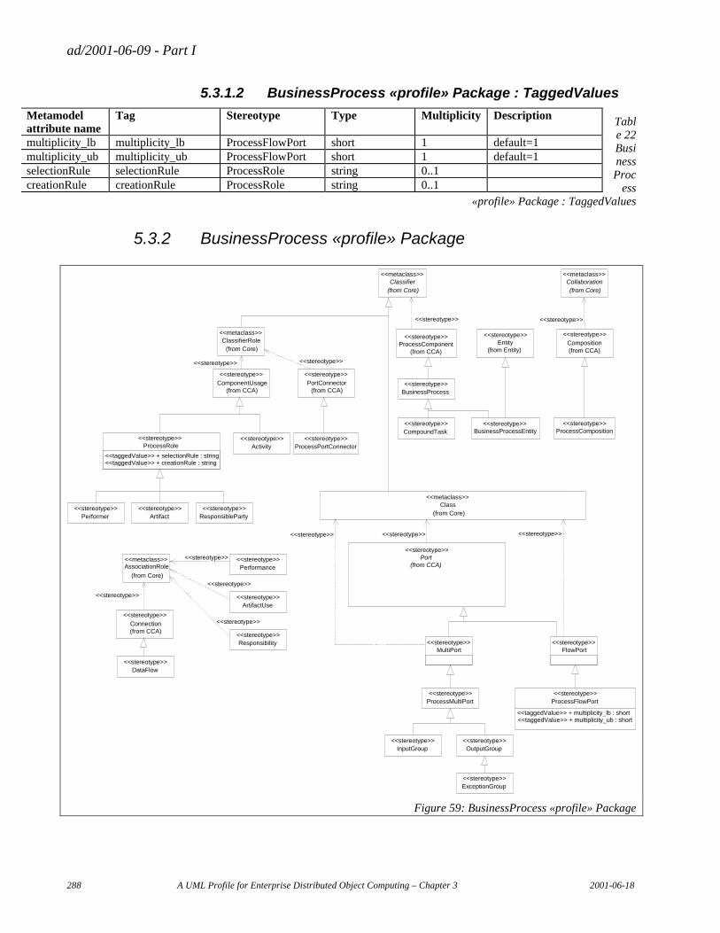
ad/2001-06-09 - Part I
288 A UML Profile for Enterprise Distributed Object Computing – Chapter 3 2001-06-18
5.3.1.2 BusinessProcess «profile» Package : TaggedValues
Table 22 BusinessProc
ess «profile» Package : TaggedValues
5.3.2 BusinessProcess «profile» Package
Class(from Core)
<<metaclass>>
FlowPort<<stereotype>>
MultiPort<<stereotype>>
Port(from CCA)
<<stereotype>>
<<stereotype>><<stereotype>> <<stereotype>>
<<stereotype>>ProcessMultiPort
<<stereotype>>ProcessFlowPort
<<taggedValue>> + multiplicity_lb : short<<taggedValue>> + multiplicity_ub : short
<<stereotype>>OutputGroup
<<stereotype>>InputGroup
<<stereotype>>ExceptionGroup
ProcessRole
<<taggedValue>> + selectionRule : string
<<stereotype>>
<<taggedValue>> + creationRule : string
<<stereotype>>Performer
<<stereotype>>Artifact
<<stereotype>>ResponsibleParty
AssociationRole
(from Core)
<<metaclass>>
<<stereotype>>
Connection(from CCA)
<<stereotype>>
<<stereotype>>DataFlow
ClassifierRole(from Core)
<<metaclass>>
<<stereotype>> <<stereotype>>
<<stereotype>>ArtifactUse
<<stereotype>>Performance
<<stereotype>>Responsibility
<<stereotype>>
<<stereotype>>
<<stereotype>>
<<stereotype>>
PortConnector(from CCA)
<<stereotype>>
<<stereotype>>Activity
ComponentUsage(from CCA)
<<stereotype>>
<<stereotype>>
<<stereotype>>CompoundTask
ProcessComponent(from CCA)
<<stereotype>>
<<stereotype>>BusinessProcess
Collaboration(from Core)
<<metaclass>>Classifier
(from Core)
<<metaclass>>
<<stereotype>>ProcessPortConnector
<<stereotype>>ProcessComposition
Composition(from CCA)
<<stereotype>>
<<stereotype>>BusinessProcessEntity
<<stereotype>>Entity
(from Entity)
Figure 59: BusinessProcess «profile» Package
Metamodel attribute name
Tag Stereotype Type Multiplicity Description
multiplicity_lb multiplicity_lb ProcessFlowPort short 1 default=1 multiplicity_ub multiplicity_ub ProcessFlowPort short 1 default=1 selectionRule selectionRule ProcessRole string 0..1 creationRule creationRule ProcessRole string 0..1
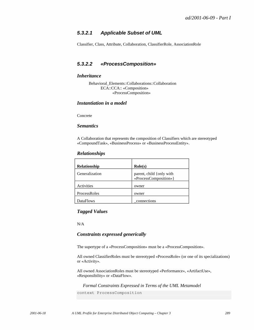
ad/2001-06-09 - Part I
2001-06-18 A UML Profile for Enterprise Distributed Object Computing – Chapter 3 289
5.3.2.1 Applicable Subset of UML
Classifier, Class, Attribute, Collaboration, ClassifierRole, AssociationRole
5.3.2.2 «ProcessComposition»
Inheritance
Behavioral_Elements::Collaborations::Collaboration ECA::CCA:: «Composition» «ProcessComposition»
Instantiation in a model
Concrete
Semantics
A Collaboration that represents the composition of Classifiers which are stereotyped «CompoundTask», «BusinessProcess» or «BusinessProcessEntity».
Relationships
Relationship Role(s)
Generalization parent, child {only with «ProcessComposition»}
Activities owner
ProcessRoles owner
DataFlows _connections
Tagged Values
N/A
Constraints expressed generically
The supertype of a «ProcessComposition» must be a «ProcessComposition».
All owned ClassifierRoles must be stereotyped «ProcessRole» (or one of its specializations) or «Activity».
All owned AssociationRoles must be stereotyped «Performance», «ArtifactUse», «Responsibility» or «DataFlow».
Formal Constraints Expressed in Terms of the UML Metamodel
context ProcessComposition
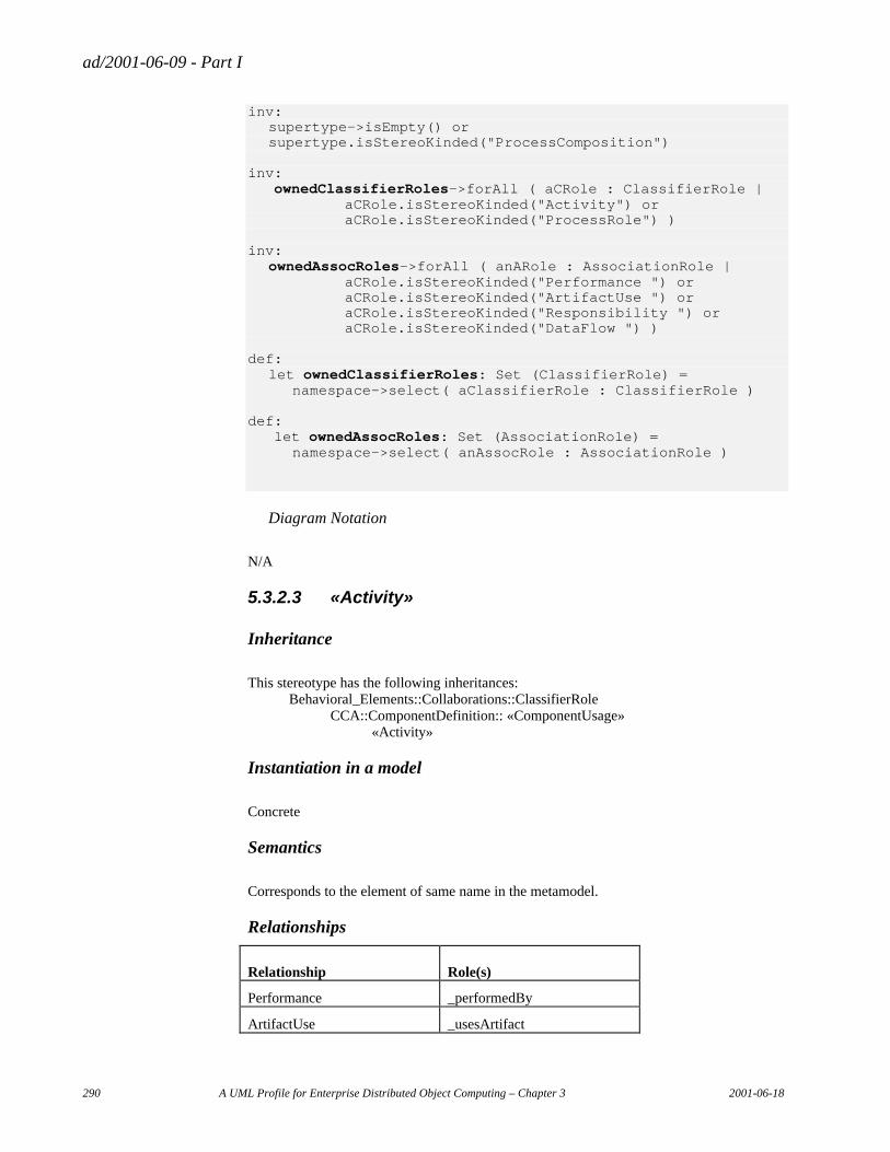
ad/2001-06-09 - Part I
290 A UML Profile for Enterprise Distributed Object Computing – Chapter 3 2001-06-18
inv: supertype->isEmpty() or
supertype.isStereoKinded("ProcessComposition") inv: ownedClassifierRoles->forAll ( aCRole : ClassifierRole | aCRole.isStereoKinded("Activity") or aCRole.isStereoKinded("ProcessRole") ) inv: ownedAssocRoles->forAll ( anARole : AssociationRole | aCRole.isStereoKinded("Performance ") or aCRole.isStereoKinded("ArtifactUse ") or aCRole.isStereoKinded("Responsibility ") or aCRole.isStereoKinded("DataFlow ") ) def: let ownedClassifierRoles: Set (ClassifierRole) =
namespace->select( aClassifierRole : ClassifierRole ) def: let ownedAssocRoles: Set (AssociationRole) =
namespace->select( anAssocRole : AssociationRole )
Diagram Notation
N/A
5.3.2.3 «Activity»
Inheritance
This stereotype has the following inheritances: Behavioral_Elements::Collaborations::ClassifierRole CCA::ComponentDefinition:: «ComponentUsage» «Activity»
Instantiation in a model
Concrete
Semantics
Corresponds to the element of same name in the metamodel.
Relationships
Relationship Role(s)
Performance _performedBy
ArtifactUse _usesArtifact
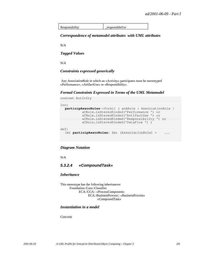
ad/2001-06-09 - Part I
2001-06-18 A UML Profile for Enterprise Distributed Object Computing – Chapter 3 291
Responsibility _responsibleFor
Correspondence of metamodel attributes with UML attributes
N/A
Tagged Values
N/A
Constraints expressed generically
Any AssociationRole in which an «Activity» participates must be stereotyped «Performance», «ArtifactUse» or «Responsibility».
Formal Constraints Expressed in Terms of the UML Metamodel context Activity inv: participAssocRoles->forAll ( anARole : AssociationRole | aCRole.isStereoKinded("Performance ") or aCRole.isStereoKinded("ArtifactUse ") or aCRole.isStereoKinded("Responsibility ") or aCRole.isStereoKinded("DataFlow ") ) def: let participAssocRoles: Set (AssociationRole) = ...
Diagram Notation
N/A
5.3.2.4 «CompoundTask»
Inheritance
This stereotype has the following inheritances: Foundation::Core::Classifier ECA::CCA:: «ProcessComponent» ECA::BusinessProcess:: «BusinessProcess» «CompoundTask»
Instantiation in a model
Concrete
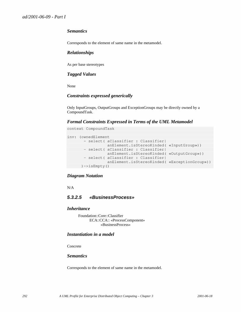
ad/2001-06-09 - Part I
292 A UML Profile for Enterprise Distributed Object Computing – Chapter 3 2001-06-18
Semantics
Corresponds to the element of same name in the metamodel.
Relationships
As per base stereotypes
Tagged Values
None
Constraints expressed generically
Only InputGroups, OutputGroups and ExceptionGroups may be directly owned by a CompoundTask.
Formal Constraints Expressed in Terms of the UML Metamodel context CompoundTask inv: (ownedElement - select( aClassifier : Classifier| anElement.isStereoKinded( «InputGroup»)) - select( aClassifier : Classifier| anElement.isStereoKinded( «OutputGroup»)) - select( aClassifier : Classifier| anElement.isStereoKinded( «ExceptionGroup»)) )->isEmpty()
Diagram Notation
N/A
5.3.2.5 «BusinessProcess»
Inheritance
Foundation::Core::Classifier ECA::CCA:: «ProcessComponent» «BusinessProcess»
Instantiation in a model
Concrete
Semantics
Corresponds to the element of same name in the metamodel.
ad/2001-06-09 - Part I
2001-06-18 A UML Profile for Enterprise Distributed Object Computing – Chapter 3 293
Relationships
As per base stereotypes
Tagged Values
None
Constraints expressed generically
N/A
Formal Constraints Expressed in Terms of the UML Metamodel
N/A
Diagram Notation
N/A
5.3.2.6 «BusinessProcessEntity»
Inheritance
This stereotype has the following inheritances: Foundation::Core::Classifier ECA::CCA:: «ProcessComponent» «BusinessProcessEntity» ECA::Entity:: «Entity» «BusinessProcessEntity»
Instantiation in a model
Concrete
Semantics
Corresponds to the element of same name in the metamodel.
Relationships
As per base stereotypes
Tagged Values
None
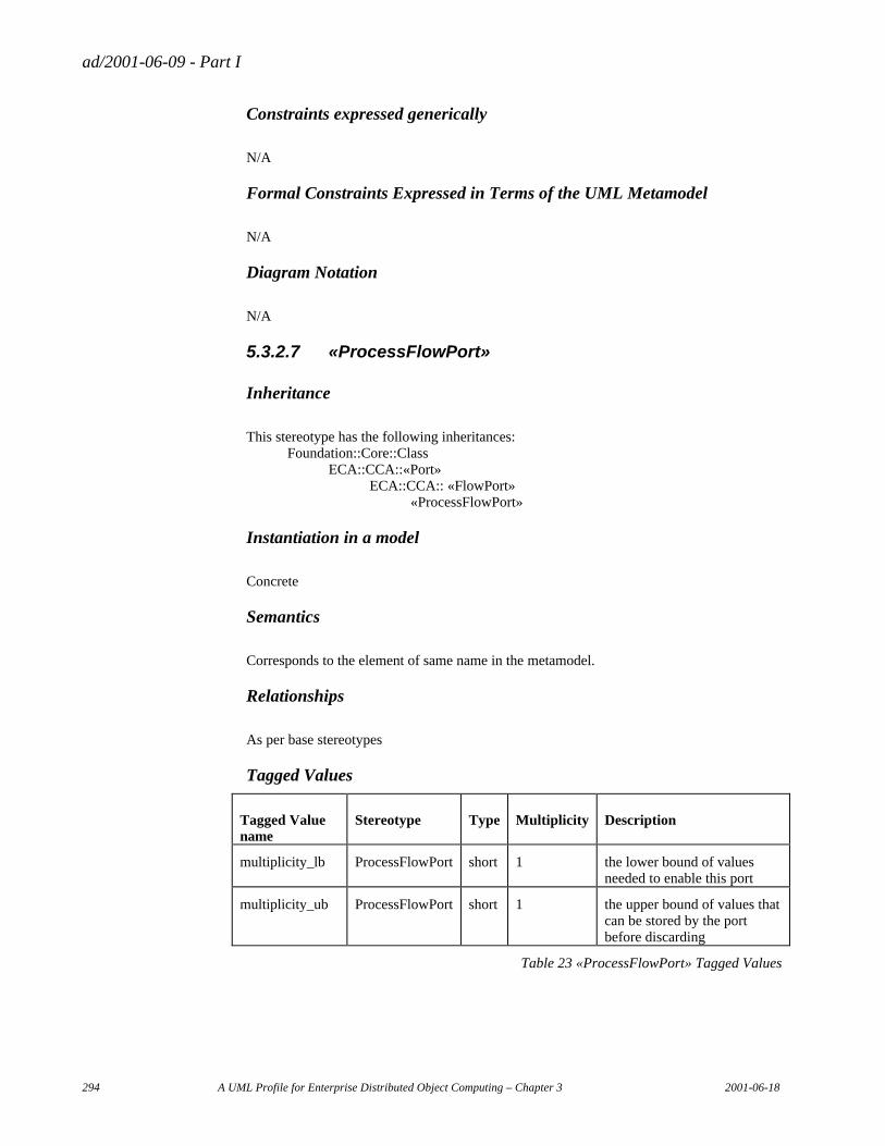
ad/2001-06-09 - Part I
294 A UML Profile for Enterprise Distributed Object Computing – Chapter 3 2001-06-18
Constraints expressed generically
N/A
Formal Constraints Expressed in Terms of the UML Metamodel
N/A
Diagram Notation
N/A
5.3.2.7 «ProcessFlowPort»
Inheritance
This stereotype has the following inheritances: Foundation::Core::Class ECA::CCA::«Port» ECA::CCA:: «FlowPort» «ProcessFlowPort»
Instantiation in a model
Concrete
Semantics
Corresponds to the element of same name in the metamodel.
Relationships
As per base stereotypes
Tagged Values
Tagged Value name
Stereotype Type Multiplicity Description
multiplicity_lb ProcessFlowPort short 1 the lower bound of values needed to enable this port
multiplicity_ub ProcessFlowPort short 1 the upper bound of values that can be stored by the port before discarding
Table 23 «ProcessFlowPort» Tagged Values
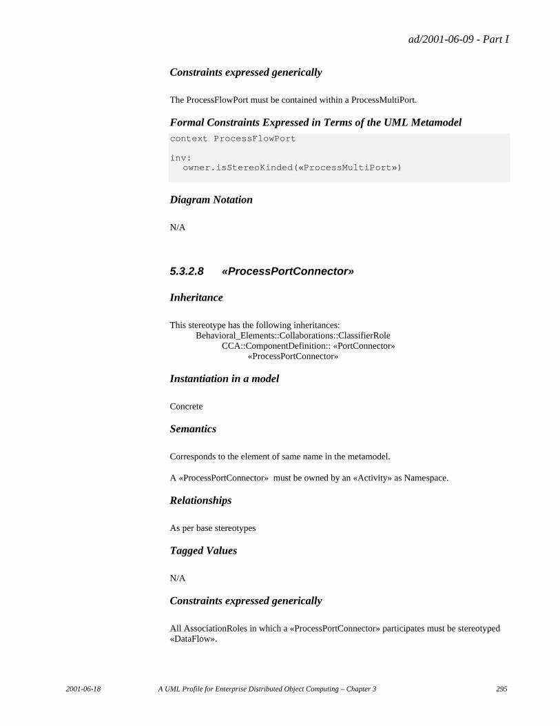
ad/2001-06-09 - Part I
2001-06-18 A UML Profile for Enterprise Distributed Object Computing – Chapter 3 295
Constraints expressed generically
The ProcessFlowPort must be contained within a ProcessMultiPort.
Formal Constraints Expressed in Terms of the UML Metamodel context ProcessFlowPort inv: owner.isStereoKinded(«ProcessMultiPort»)
Diagram Notation
N/A
5.3.2.8 «ProcessPortConnector»
Inheritance
This stereotype has the following inheritances: Behavioral_Elements::Collaborations::ClassifierRole CCA::ComponentDefinition:: «PortConnector» «ProcessPortConnector»
Instantiation in a model
Concrete
Semantics
Corresponds to the element of same name in the metamodel.
A «ProcessPortConnector» must be owned by an «Activity» as Namespace.
Relationships
As per base stereotypes
Tagged Values
N/A
Constraints expressed generically
All AssociationRoles in which a «ProcessPortConnector» participates must be stereotyped «DataFlow».
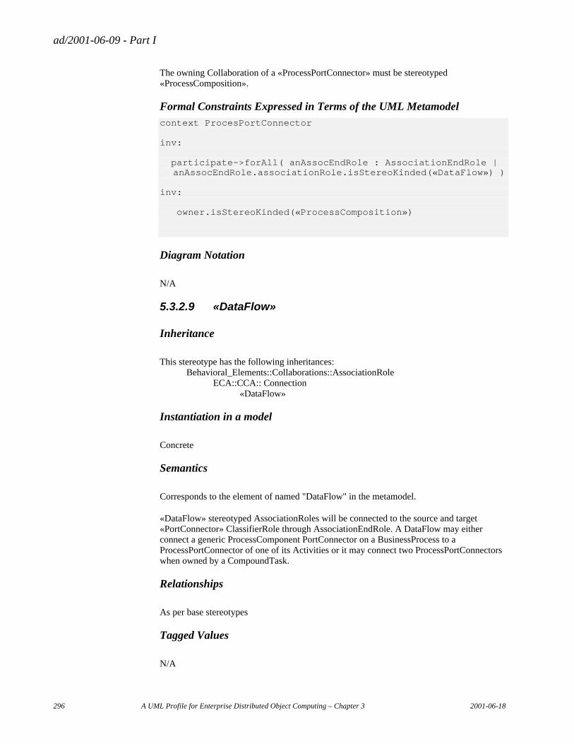
ad/2001-06-09 - Part I
296 A UML Profile for Enterprise Distributed Object Computing – Chapter 3 2001-06-18
The owning Collaboration of a «ProcessPortConnector» must be stereotyped «ProcessComposition».
Formal Constraints Expressed in Terms of the UML Metamodel context ProcesPortConnector inv: participate->forAll( anAssocEndRole : AssociationEndRole | anAssocEndRole.associationRole.isStereoKinded(«DataFlow») ) inv: owner.isStereoKinded(«ProcessComposition»)
Diagram Notation
N/A
5.3.2.9 «DataFlow»
Inheritance
This stereotype has the following inheritances: Behavioral_Elements::Collaborations::AssociationRole ECA::CCA:: Connection «DataFlow»
Instantiation in a model
Concrete
Semantics
Corresponds to the element of named "DataFlow" in the metamodel.
«DataFlow» stereotyped AssociationRoles will be connected to the source and target «PortConnector» ClassifierRole through AssociationEndRole. A DataFlow may either connect a generic ProcessComponent PortConnector on a BusinessProcess to a ProcessPortConnector of one of its Activities or it may connect two ProcessPortConnectors when owned by a CompoundTask.
Relationships
As per base stereotypes
Tagged Values
N/A
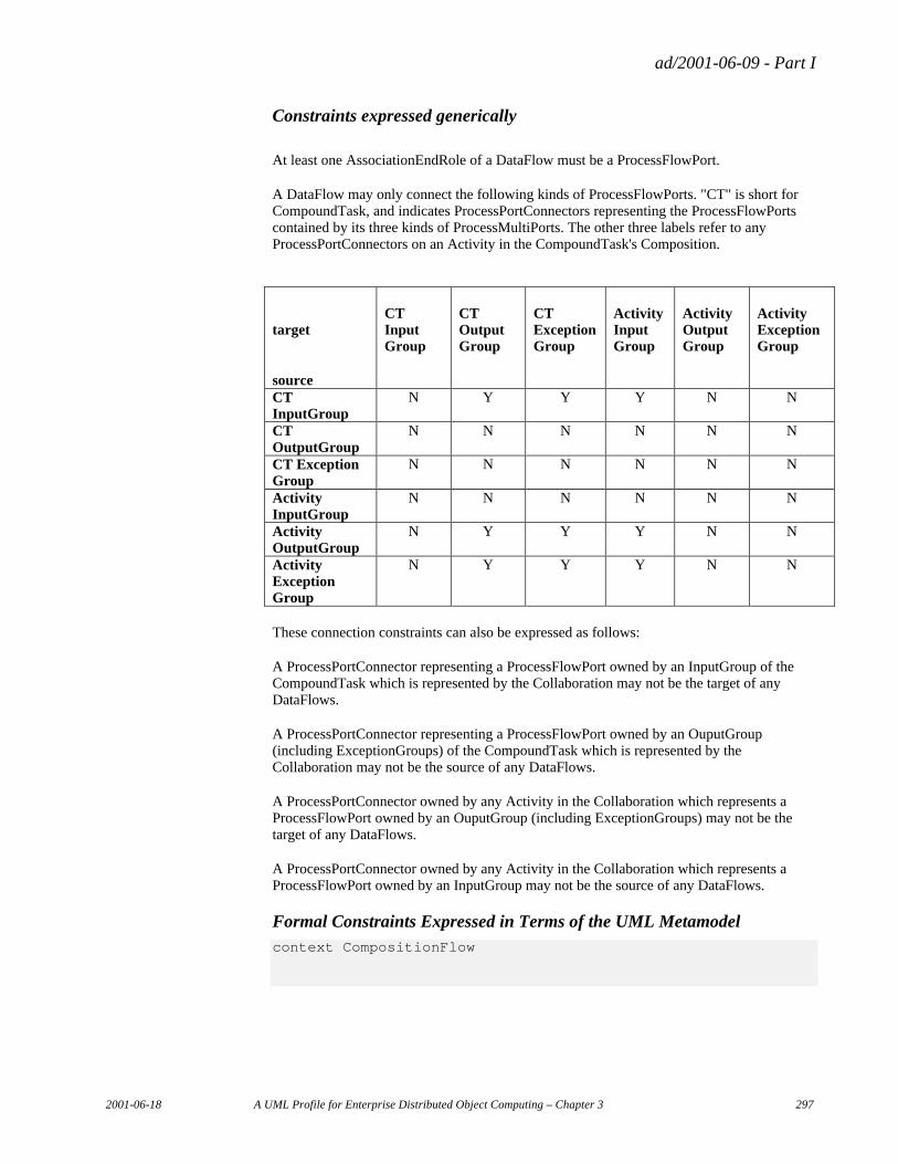
ad/2001-06-09 - Part I
2001-06-18 A UML Profile for Enterprise Distributed Object Computing – Chapter 3 297
Constraints expressed generically
At least one AssociationEndRole of a DataFlow must be a ProcessFlowPort.
A DataFlow may only connect the following kinds of ProcessFlowPorts. "CT" is short for CompoundTask, and indicates ProcessPortConnectors representing the ProcessFlowPorts contained by its three kinds of ProcessMultiPorts. The other three labels refer to any ProcessPortConnectors on an Activity in the CompoundTask's Composition.
target
source
CT Input Group
CT Output Group
CT Exception Group
Activity Input Group
Activity Output Group
Activity Exception Group
CT InputGroup
N Y Y Y N N
CT OutputGroup
N N N N N N
CT Exception Group
N N N N N N
Activity InputGroup
N N N N N N
Activity OutputGroup
N Y Y Y N N
Activity Exception Group
N Y Y Y N N
These connection constraints can also be expressed as follows:
A ProcessPortConnector representing a ProcessFlowPort owned by an InputGroup of the CompoundTask which is represented by the Collaboration may not be the target of any DataFlows.
A ProcessPortConnector representing a ProcessFlowPort owned by an OuputGroup (including ExceptionGroups) of the CompoundTask which is represented by the Collaboration may not be the source of any DataFlows.
A ProcessPortConnector owned by any Activity in the Collaboration which represents a ProcessFlowPort owned by an OuputGroup (including ExceptionGroups) may not be the target of any DataFlows.
A ProcessPortConnector owned by any Activity in the Collaboration which represents a ProcessFlowPort owned by an InputGroup may not be the source of any DataFlows.
Formal Constraints Expressed in Terms of the UML Metamodel context CompositionFlow
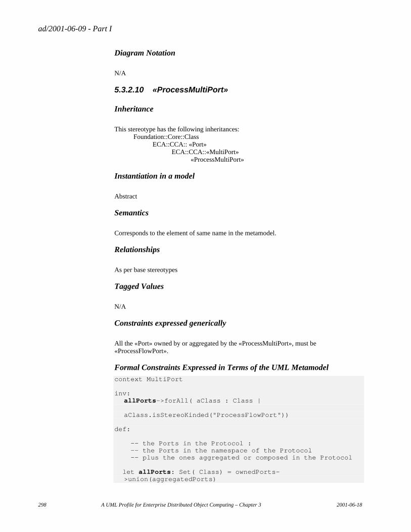
ad/2001-06-09 - Part I
298 A UML Profile for Enterprise Distributed Object Computing – Chapter 3 2001-06-18
Diagram Notation
N/A
5.3.2.10 «ProcessMultiPort»
Inheritance
This stereotype has the following inheritances: Foundation::Core::Class ECA::CCA:: «Port» ECA::CCA::«MultiPort» «ProcessMultiPort»
Instantiation in a model
Abstract
Semantics
Corresponds to the element of same name in the metamodel.
Relationships
As per base stereotypes
Tagged Values
N/A
Constraints expressed generically
All the «Port» owned by or aggregated by the «ProcessMultiPort», must be «ProcessFlowPort».
Formal Constraints Expressed in Terms of the UML Metamodel context MultiPort inv: allPorts->forAll( aClass : Class |
aClass.isStereoKinded("ProcessFlowPort"))
def: -- the Ports in the Protocol : -- the Ports in the namespace of the Protocol -- plus the ones aggregated or composed in the Protocol let allPorts: Set( Class) = ownedPorts-
>union(aggregatedPorts)
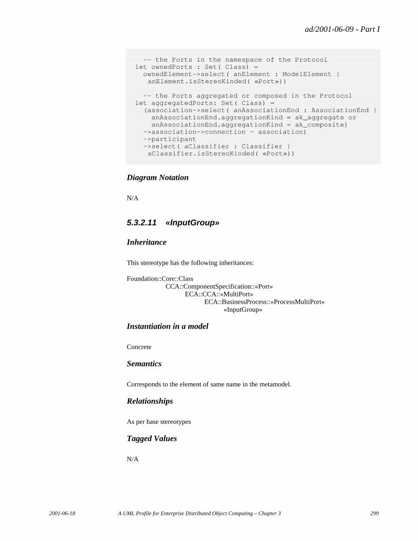
ad/2001-06-09 - Part I
2001-06-18 A UML Profile for Enterprise Distributed Object Computing – Chapter 3 299
-- the Ports in the namespace of the Protocol let ownedPorts : Set( Class) = ownedElement->select( anElement : ModelElement | anElement.isStereoKinded( «Port»)) -- the Ports aggregated or composed in the Protocol let aggregatedPorts: Set( Class) = (association->select( anAssociationEnd : AssociationEnd | anAssociationEnd.aggregationKind = ak_aggregate or anAssociationEnd.aggregationKind = ak_composite) ->association->connection – association) ->participant ->select( aClassifier : Classifier | aClassifier.isStereoKinded( «Port»))
Diagram Notation
N/A
5.3.2.11 «InputGroup»
Inheritance
This stereotype has the following inheritances:
Foundation::Core::Class CCA::ComponentSpecification::«Port» ECA::CCA::«MultiPort» ECA::BusinessProcess::«ProcessMultiPort» «InputGroup»
Instantiation in a model
Concrete
Semantics
Corresponds to the element of same name in the metamodel.
Relationships
As per base stereotypes
Tagged Values
N/A
ad/2001-06-09 - Part I
300 A UML Profile for Enterprise Distributed Object Computing – Chapter 3 2001-06-18
Constraints expressed generically
N/A
Formal Constraints Expressed in Terms of the UML Metamodel
N/A
5.3.2.12 «OutputGroup»
Inheritance
This stereotype has the following inheritances: Foundation::Core::Class CCA::ComponentSpecification::«Port» ECA::CCA::«MultiPort» ECA::BusinessProcess::«ProcessMultiPort» «OutputGroup»
Instantiation in a model
Concrete
Semantics
Corresponds to the element of same name in the metamodel.
Relationships
As per base stereotypes
Tagged Values
N/A
Constraints expressed generically
N/A
Formal Constraints Expressed in Terms of the UML Metamodel
N.A
ad/2001-06-09 - Part I
2001-06-18 A UML Profile for Enterprise Distributed Object Computing – Chapter 3 301
5.3.2.13 «ExceptionGroup»
Inheritance
This stereotype has the following inheritances: Foundation::Core::Class CCA::ComponentSpecification::«Port» CCA::ComponentSpecification::«MultiPort» CCA::BusinessProcess::«ProcessMultiPort» CCA::BusinessProcess::«OutputGroup» «ExceptionGroup»
Instantiation in a model
Concrete
Semantics
Corresponds to the element of same name in the metamodel.
Relationships
As per base stereotypes
Tagged Values
N/A
Constraints expressed generically
All the «Port» owned by or aggregated by the «ProcessMultiPort», must be «ProcessFlowPort».
Formal Constraints Expressed in Terms of the UML Metamodel
5.3.2.14 «ProcessRole»
Inheritance
This stereotype has the following inheritances: Behavioral_Elements::Collaborations::ClassifierRole «ProcessRole»
Instantiation in a model
Concrete
ad/2001-06-09 - Part I
302 A UML Profile for Enterprise Distributed Object Computing – Chapter 3 2001-06-18
Semantics
Corresponds to the element of same name in the metamodel.
Relationships
Relationship Role(s)
Performance performedBy
ArtifactUse usesArtifact
Responsibility responsibleFor
Tagged Values
Tagged Value name
Stereotype Type Multiplicity Description
selectionRule ProcessRole string 0..1 an expression indicating an object or objects to be bound to the Role
creationRule ProcessRole short 0..1 an expression giving sufficient arguments to a constructor for a new object instance to be created
Table 24«ProcessRole» Tagged Values
Constraints expressed generically
Formal Constraints Expressed in Terms of the UML Metamodel context ProcessRole
Diagram Notation
N/A
5.3.2.15 «Performer»
Inheritance
This stereotype has the following inheritances: Behavioral_Elements::Collaborations::ClassifierRole CCA::BusinessProcess:: «ProcessRole» «Performer»
Instantiation in a model
Concrete
ad/2001-06-09 - Part I
2001-06-18 A UML Profile for Enterprise Distributed Object Computing – Chapter 3 303
Semantics
Corresponds to the element of same name in the metamodel.
Relationships
As per base stereotypes
Tagged Values
Constraints expressed generically
This specialization of «ProcessRole» may only participate in AssociationRoles stereotyped «Performance».
Formal Constraints Expressed in Terms of the UML Metamodel context ProcessRole inv: participates->forAll( anAssocEndRole : AssociationEndRole |
anAssocEndRole.associationRole.isStereoKinded(«Performance») )
Diagram Notation
N/A
5.3.2.16 «Artifact»
Inheritance
This stereotype has the following inheritances: Behavioral_Elements::Collaborations::ClassifierRole CCA::BusinessProcess:: «ProcessRole» «Artifact»
Instantiation in a model
Concrete
Semantics
Corresponds to the element of same name in the metamodel.
ad/2001-06-09 - Part I
304 A UML Profile for Enterprise Distributed Object Computing – Chapter 3 2001-06-18
Relationships
As per base stereotypes
Tagged Values
Constraints expressed generically
This specialization of «ProcessRole» may only participate in AssociationRoles stereotyped «ArtifactUse».
Formal Constraints Expressed in Terms of the UML Metamodel context Artifact inv: participates->forAll( anAssocEndRole : AssociationEndRole |
anAssocEndRole.associationRole.isStereoKinded(«ArtifactUse») )
Diagram Notation
N/A
5.3.2.17 «ResponsibleParty»
Inheritance
This stereotype has the following inheritances: Behavioral_Elements::Collaborations::ClassifierRole CCA::BusinessProcess:: «ProcessRole» «ResponsibleParty»
Instantiation in a model
Concrete
Semantics
Corresponds to the element of same name in the metamodel.
Relationships
As per base stereotypes
ad/2001-06-09 - Part I
2001-06-18 A UML Profile for Enterprise Distributed Object Computing – Chapter 3 305
Tagged Values
Constraints expressed generically
This specialization of «ProcessRole» may only participate in AssociationRoles stereotyped «Responsibility».
Formal Constraints Expressed in Terms of the UML Metamodel context ResponsibleParty inv: participates->forAll( anAssocEndRole : AssociationEndRole |
anAssocEndRole.associationRole.isStereoKinded(«Responsibility») )
Diagram Notation
N/A
5.3.2.18 «Performance»
Inheritance
This stereotype has the following inheritances: Behavioral_Elements::Collaborations::AssociationRole «Performance»
Instantiation in a model
Concrete
Semantics
Corresponds to the element of same name in the metamodel.
Relationships
As per base stereotypes
Tagged Values
Constraints expressed generically
The AssociationRole must have an AssociationRoleEnd named performedBy, which must have stereotype kind «ProcessRole».
ad/2001-06-09 - Part I
306 A UML Profile for Enterprise Distributed Object Computing – Chapter 3 2001-06-18
The AssociationRole must have an AssociationRoleEnd named _performedBy, which must have stereotype kind «Activity».
Formal Constraints Expressed in Terms of the UML Metamodel context Performance:
Diagram Notation
N/A
5.3.2.19 «ArtifactUse»
Inheritance
This stereotype has the following inheritances: Behavioral_Elements::Collaborations::AssociationRole «ArtifactUse»
Instantiation in a model
Concrete
Semantics
Corresponds to the element of same name in the metamodel.
Relationships
As per base stereotypes
Tagged Values
Constraints expressed generically
The AssociationRole must have an AssociationRoleEnd named usesArtifact, which must have stereotype kind «ProcessRole».
The AssociationRole must have an AssociationRoleEnd named _usesArtifact, which must have stereotype kind «Activity».
Formal Constraints Expressed in Terms of the UML Metamodel context ArtifactUse:
ad/2001-06-09 - Part I
2001-06-18 A UML Profile for Enterprise Distributed Object Computing – Chapter 3 307
Diagram Notation
N/A
5.3.2.20 «Responsibility»
Inheritance
This stereotype has the following inheritances: Behavioral_Elements::Collaborations::AssociationRole «Responsibility»
Instantiation in a model
Concrete
Semantics
Corresponds to the element of same name in the metamodel.
Relationships
As per base stereotypes
Tagged Values
N/A
Constraints expressed generically
The AssociationRole must have an AssociationRoleEnd named responsibleFor, which must have stereotype kind «ProcessRole».
The AssociationRole must have an AssociationRoleEnd named _responsibleFor, which must have stereotype kind «Activity».
Formal Constraints Expressed in Terms of the UML Metamodel context Responsibility:
Diagram Notation
N/A
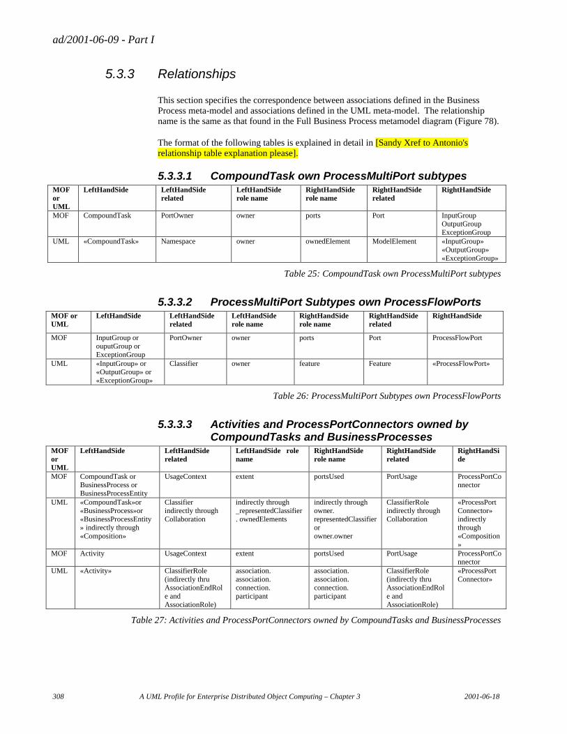
ad/2001-06-09 - Part I
308 A UML Profile for Enterprise Distributed Object Computing – Chapter 3 2001-06-18
5.3.3 Relationships
This section specifies the correspondence between associations defined in the Business Process meta-model and associations defined in the UML meta-model. The relationship name is the same as that found in the Full Business Process metamodel diagram (Figure 78).
The format of the following tables is explained in detail in [Sandy Xref to Antonio's relationship table explanation please].
5.3.3.1 CompoundTask own ProcessMultiPort subtypes MOF or UML
LeftHandSide LeftHandSide related
LeftHandSide role name
RightHandSide role name
RightHandSide related
RightHandSide
MOF CompoundTask PortOwner owner ports Port InputGroup OutputGroup ExceptionGroup
UML «CompoundTask» Namespace owner ownedElement ModelElement «InputGroup» «OutputGroup» «ExceptionGroup»
Table 25: CompoundTask own ProcessMultiPort subtypes
5.3.3.2 ProcessMultiPort Subtypes own ProcessFlowPorts MOF or UML
LeftHandSide LeftHandSide related
LeftHandSide role name
RightHandSide role name
RightHandSide related
RightHandSide
MOF InputGroup or ouputGroup or ExceptionGroup
PortOwner owner ports Port ProcessFlowPort
UML «InputGroup» or «OutputGroup» or «ExceptionGroup»
Classifier owner feature Feature «ProcessFlowPort»
Table 26: ProcessMultiPort Subtypes own ProcessFlowPorts
5.3.3.3 Activities and ProcessPortConnectors owned by CompoundTasks and BusinessProcesses
MOF or UML
LeftHandSide LeftHandSide related
LeftHandSide role name
RightHandSide role name
RightHandSide related
RightHandSide
MOF CompoundTask or BusinessProcess or BusinessProcessEntity
UsageContext extent portsUsed PortUsage ProcessPortConnector
UML «CompoundTask»or «BusinessProcess»or «BusinessProcessEntity» indirectly through «Composition»
Classifier indirectly through Collaboration
indirectly through _representedClassifier. ownedElements
indirectly through owner. representedClassifier or owner.owner
ClassifierRole indirectly through Collaboration
«ProcessPortConnector» indirectly through «Composition»
MOF Activity UsageContext extent portsUsed PortUsage ProcessPortConnector
UML «Activity» ClassifierRole (indirectly thru AssociationEndRole and AssociationRole)
association. association. connection. participant
association. association. connection. participant
ClassifierRole (indirectly thru AssociationEndRole and AssociationRole)
«ProcessPortConnector»
Table 27: Activities and ProcessPortConnectors owned by CompoundTasks and BusinessProcesses
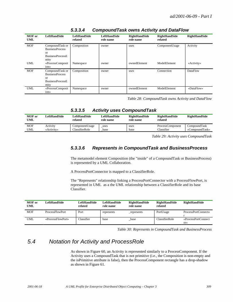
ad/2001-06-09 - Part I
2001-06-18 A UML Profile for Enterprise Distributed Object Computing – Chapter 3 309
5.3.3.4 CompoundTask owns Activity and DataFlow MOF or UML
LeftHandSide LeftHandSide related
LeftHandSide role name
RightHandSide role name
RightHandSide related
RightHandSide
MOF CompoundTask or BusinessProcess or BusinessProcessEntity
Composition owner uses ComponentUsage Activity
UML «ProcessComposition»
Namespace owner ownedElement ModelElement «Activity»
MOF CompoundTask or BusinessProcess or BusinessProcessEntity
Composition owner uses Connection DataFlow
UML «ProcessComposition»
Namespace owner ownedElement ModelElement «DataFlow»
Table 28: CompoundTask owns Activity and DataFlow
5.3.3.5 Activity uses CompoundTask MOF or UML
LeftHandSide LeftHandSide related
LeftHandSide role name
RightHandSide role name
RightHandSide related
RightHandSide
MOF Activity ComponentUsage _uses uses ProcessComponent CompoundTask UML «Activity» ClassifierRole _base base Classifier «CompoundTask»
Table 29: Activity uses CompoundTask
5.3.3.6 Represents in CompoundTask and BusinessProcess
The metamodel element Composition (the "inside" of a CompoundTask or BusinessProcess) is represented by a UML Collaboration.
A ProcessPortConnector is mapped to a ClassifierRole.
The "Represents" relationship linking a ProcessPortConnector with a ProcessFlowPort, is represented in UML as a the UML relationship between a ClassifierRole and its base Classifier.
MOF or UML
LeftHandSide LeftHandSide related
LeftHandSide role name
RightHandSide role name
RightHandSide related
RightHandSide
MOF ProcessFlowPort Port represents _represents PortUsage ProcessPortConnector
UML «ProcessFlowPort» Classifier base _base ClassifierRole «ProcessPortConnector»
Table 30: Represents in CompoundTask and BusinessProcess
5.4 Notation for Activity and ProcessRole
As shown in Figure 60, an Activity is represented similarly to a ProcessComponent. If the Activity uses a CompoundTask that is not primitive (i.e., the Composition is non-empty and the isPrimitive attribute is false), then the ProcessComponent rectangle has a drop-shadow as shown in Figure 61.
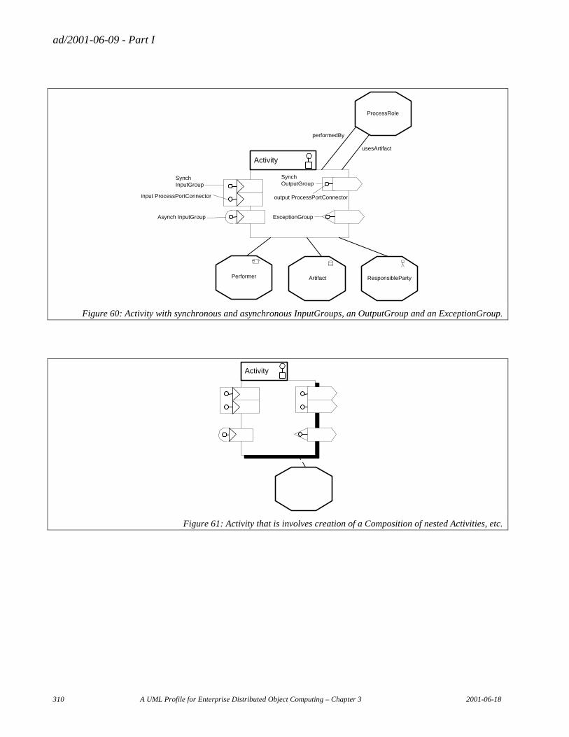
ad/2001-06-09 - Part I
310 A UML Profile for Enterprise Distributed Object Computing – Chapter 3 2001-06-18
Activity
SynchInputGroup
input ProcessPortConnector
Asynch InputGroup
performedBy
usesArtifact
SynchOutputGroup
output ProcessPortConnector
ExceptionGroup
ArtifactPerformer ResponsibleParty
ProcessRole
Figure 60: Activity with synchronous and asynchronous InputGroups, an OutputGroup and an ExceptionGroup.
Activity
Figure 61: Activity that is involves creation of a Composition of nested Activities, etc.
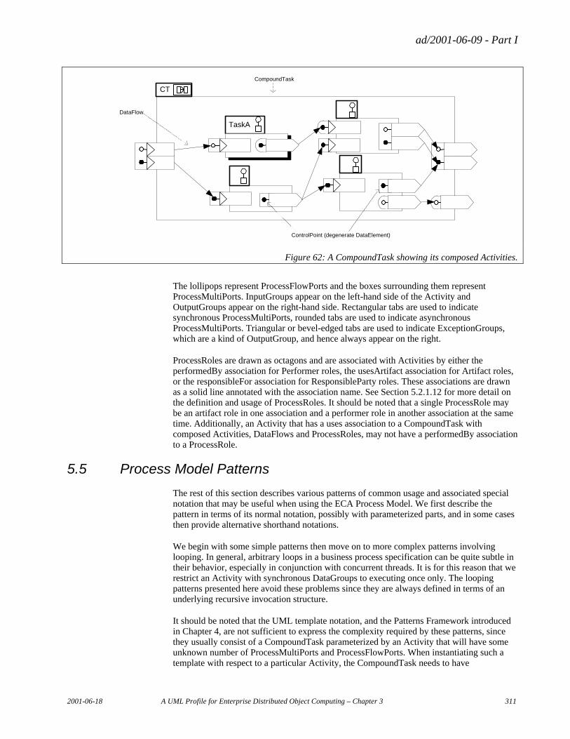
ad/2001-06-09 - Part I
2001-06-18 A UML Profile for Enterprise Distributed Object Computing – Chapter 3 311
CT
TaskA
CompoundTask
DataFlow
ControlPoint (degenerate DataElement)
Figure 62: A CompoundTask showing its composed Activities.
The lollipops represent ProcessFlowPorts and the boxes surrounding them represent ProcessMultiPorts. InputGroups appear on the left-hand side of the Activity and OutputGroups appear on the right-hand side. Rectangular tabs are used to indicate synchronous ProcessMultiPorts, rounded tabs are used to indicate asynchronous ProcessMultiPorts. Triangular or bevel-edged tabs are used to indicate ExceptionGroups, which are a kind of OutputGroup, and hence always appear on the right.
ProcessRoles are drawn as octagons and are associated with Activities by either the performedBy association for Performer roles, the usesArtifact association for Artifact roles, or the responsibleFor association for ResponsibleParty roles. These associations are drawn as a solid line annotated with the association name. See Section 5.2.1.12 for more detail on the definition and usage of ProcessRoles. It should be noted that a single ProcessRole may be an artifact role in one association and a performer role in another association at the same time. Additionally, an Activity that has a uses association to a CompoundTask with composed Activities, DataFlows and ProcessRoles, may not have a performedBy association to a ProcessRole.
5.5 Process Model Patterns
The rest of this section describes various patterns of common usage and associated special notation that may be useful when using the ECA Process Model. We first describe the pattern in terms of its normal notation, possibly with parameterized parts, and in some cases then provide alternative shorthand notations.
We begin with some simple patterns then move on to more complex patterns involving looping. In general, arbitrary loops in a business process specification can be quite subtle in their behavior, especially in conjunction with concurrent threads. It is for this reason that we restrict an Activity with synchronous DataGroups to executing once only. The looping patterns presented here avoid these problems since they are always defined in terms of an underlying recursive invocation structure.
It should be noted that the UML template notation, and the Patterns Framework introduced in Chapter 4, are not sufficient to express the complexity required by these patterns, since they usually consist of a CompoundTask parameterized by an Activity that will have some unknown number of ProcessMultiPorts and ProcessFlowPorts. When instantiating such a template with respect to a particular Activity, the CompoundTask needs to have
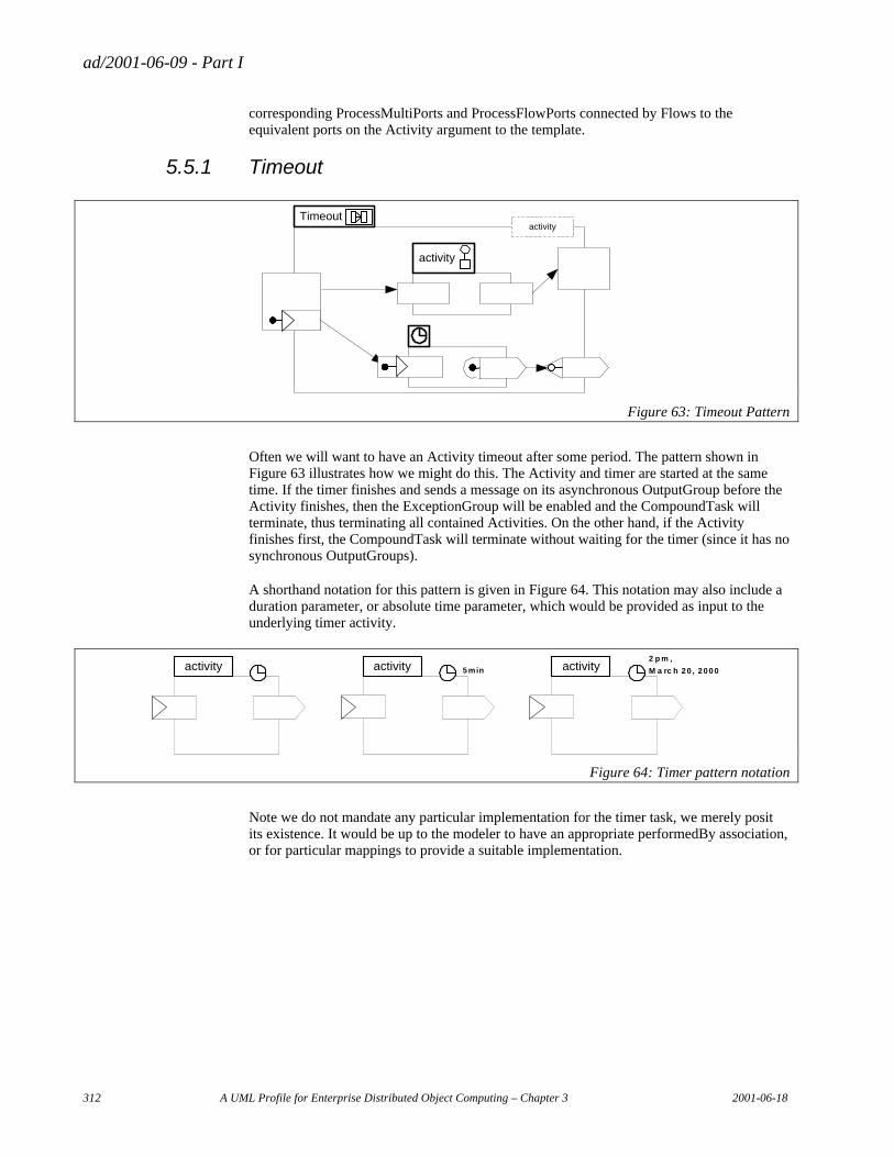
ad/2001-06-09 - Part I
312 A UML Profile for Enterprise Distributed Object Computing – Chapter 3 2001-06-18
corresponding ProcessMultiPorts and ProcessFlowPorts connected by Flows to the equivalent ports on the Activity argument to the template.
5.5.1 Timeout
activity
Timeoutactivity
Figure 63: Timeout Pattern
Often we will want to have an Activity timeout after some period. The pattern shown in Figure 63 illustrates how we might do this. The Activity and timer are started at the same time. If the timer finishes and sends a message on its asynchronous OutputGroup before the Activity finishes, then the ExceptionGroup will be enabled and the CompoundTask will terminate, thus terminating all contained Activities. On the other hand, if the Activity finishes first, the CompoundTask will terminate without waiting for the timer (since it has no synchronous OutputGroups).
A shorthand notation for this pattern is given in Figure 64. This notation may also include a duration parameter, or absolute time parameter, which would be provided as input to the underlying timer activity.
2 p m ,
M a rc h 20, 20005minactivity activity activity
Figure 64: Timer pattern notation
Note we do not mandate any particular implementation for the timer task, we merely posit its existence. It would be up to the modeler to have an appropriate performedBy association, or for particular mappings to provide a suitable implementation.
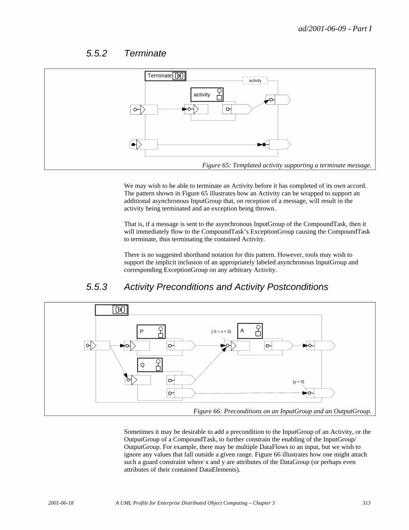
ad/2001-06-09 - Part I
2001-06-18 A UML Profile for Enterprise Distributed Object Computing – Chapter 3 313
5.5.2 Terminate
activity
Terminateactivity
Figure 65: Templated activity supporting a terminate message.
We may wish to be able to terminate an Activity before it has completed of its own accord. The pattern shown in Figure 65 illustrates how an Activity can be wrapped to support an additional asynchronous InputGroup that, on reception of a message, will result in the activity being terminated and an exception being thrown.
That is, if a message is sent to the asynchronous InputGroup of the CompoundTask, then it will immediately flow to the CompoundTask’s ExceptionGroup causing the CompoundTask to terminate, thus terminating the contained Activity.
There is no suggested shorthand notation for this pattern. However, tools may wish to support the implicit inclusion of an appropriately labeled asynchronous InputGroup and corresponding ExceptionGroup on any arbitrary Activity.
5.5.3 Activity Preconditions and Activity Postconditions
Q
AP {-5 < x < 5}
{y < 0}
Figure 66: Preconditions on an InputGroup and an OutputGroup.
Sometimes it may be desirable to add a precondition to the InputGroup of an Activity, or the OutputGroup of a CompoundTask, to further constrain the enabling of the InputGroup/ OutputGroup. For example, there may be multiple DataFlows to an input, but we wish to ignore any values that fall outside a given range. Figure 66 illustrates how one might attach such a guard constraint where x and y are attributes of the DataGroup (or perhaps even attributes of their contained DataElements).
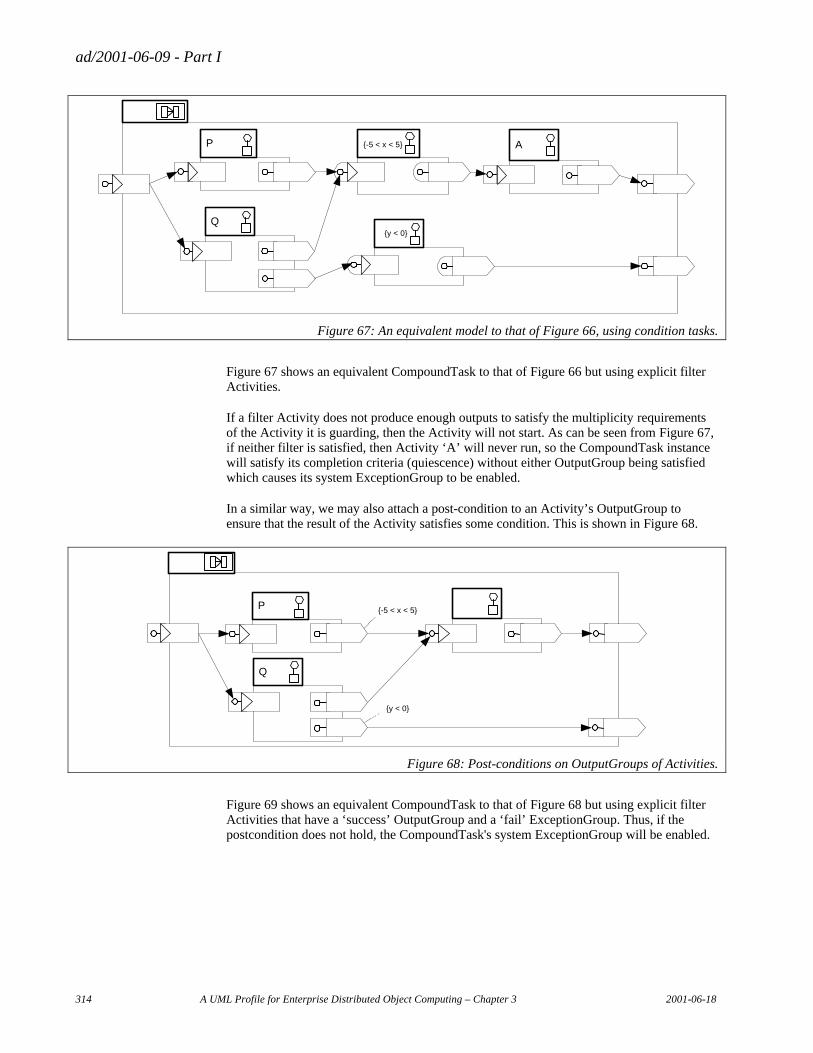
ad/2001-06-09 - Part I
314 A UML Profile for Enterprise Distributed Object Computing – Chapter 3 2001-06-18
Q
AP {-5 < x < 5}
{y < 0}
Figure 67: An equivalent model to that of Figure 66, using condition tasks.
Figure 67 shows an equivalent CompoundTask to that of Figure 66 but using explicit filter Activities.
If a filter Activity does not produce enough outputs to satisfy the multiplicity requirements of the Activity it is guarding, then the Activity will not start. As can be seen from Figure 67, if neither filter is satisfied, then Activity ‘A’ will never run, so the CompoundTask instance will satisfy its completion criteria (quiescence) without either OutputGroup being satisfied which causes its system ExceptionGroup to be enabled.
In a similar way, we may also attach a post-condition to an Activity’s OutputGroup to ensure that the result of the Activity satisfies some condition. This is shown in Figure 68.
Q
P {-5 < x < 5}
{y < 0}
Figure 68: Post-conditions on OutputGroups of Activities.
Figure 69 shows an equivalent CompoundTask to that of Figure 68 but using explicit filter Activities that have a ‘success’ OutputGroup and a ‘fail’ ExceptionGroup. Thus, if the postcondition does not hold, the CompoundTask's system ExceptionGroup will be enabled.
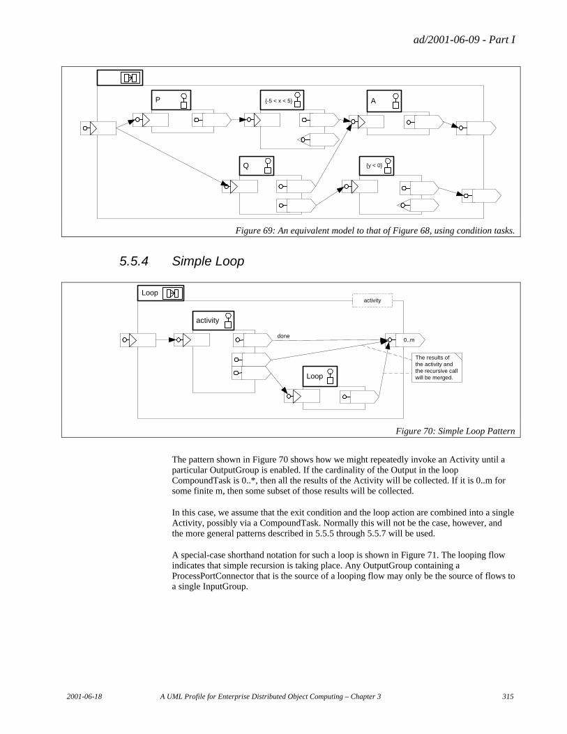
ad/2001-06-09 - Part I
2001-06-18 A UML Profile for Enterprise Distributed Object Computing – Chapter 3 315
Q
AP {-5 < x < 5}
{y < 0}
Figure 69: An equivalent model to that of Figure 68, using condition tasks.
5.5.4 Simple Loop
activity
Loopactivity
Loop
done
The results ofthe activity andthe recursive callwill be merged.
0..m
Figure 70: Simple Loop Pattern
The pattern shown in Figure 70 shows how we might repeatedly invoke an Activity until a particular OutputGroup is enabled. If the cardinality of the Output in the loop CompoundTask is 0..*, then all the results of the Activity will be collected. If it is 0..m for some finite m, then some subset of those results will be collected.
In this case, we assume that the exit condition and the loop action are combined into a single Activity, possibly via a CompoundTask. Normally this will not be the case, however, and the more general patterns described in 5.5.5 through 5.5.7 will be used.
A special-case shorthand notation for such a loop is shown in Figure 71. The looping flow indicates that simple recursion is taking place. Any OutputGroup containing a ProcessPortConnector that is the source of a looping flow may only be the source of flows to a single InputGroup.
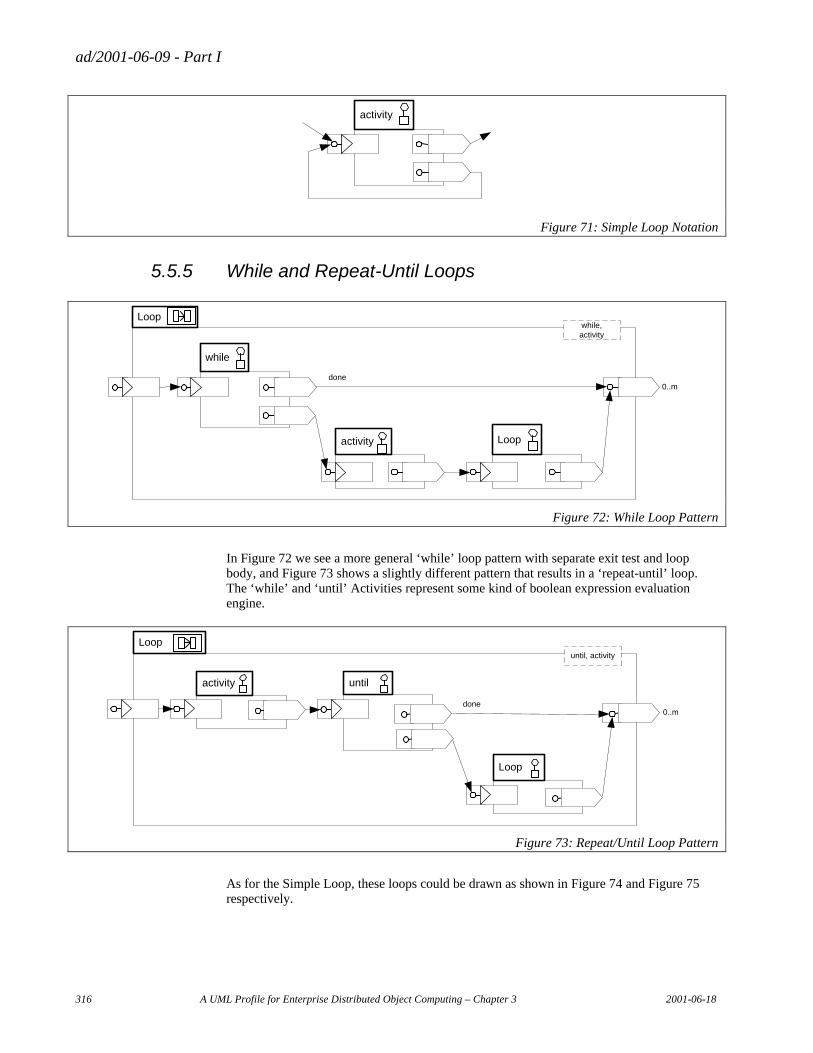
ad/2001-06-09 - Part I
316 A UML Profile for Enterprise Distributed Object Computing – Chapter 3 2001-06-18
activity
Figure 71: Simple Loop Notation
5.5.5 While and Repeat-Until Loops
while
Loopwhile,activity
Loop
done0..m
activity
Figure 72: While Loop Pattern
In Figure 72 we see a more general ‘while’ loop pattern with separate exit test and loop body, and Figure 73 shows a slightly different pattern that results in a ‘repeat-until’ loop. The ‘while’ and ‘until’ Activities represent some kind of boolean expression evaluation engine.
until
Loopuntil, activity
Loop
done0..m
activity
Figure 73: Repeat/Until Loop Pattern
As for the Simple Loop, these loops could be drawn as shown in Figure 74 and Figure 75 respectively.
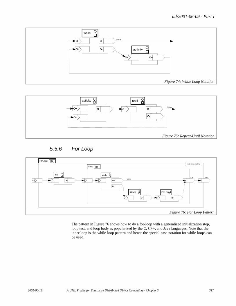
ad/2001-06-09 - Part I
2001-06-18 A UML Profile for Enterprise Distributed Object Computing – Chapter 3 317
activity
while
done
Figure 74: While Loop Notation
untilactivity
done
Figure 75: Repeat-Until Notation
5.5.6 For Loop
while
Loop
ForLoop
done0..m
activity
ForLoop
init0..m
init, while, activity
Figure 76: For Loop Pattern
The pattern in Figure 76 shows how to do a for-loop with a generalized initialization step, loop test, and loop body as popularized by the C, C++, and Java languages. Note that the inner loop is the while-loop pattern and hence the special-case notation for while-loops can be used.
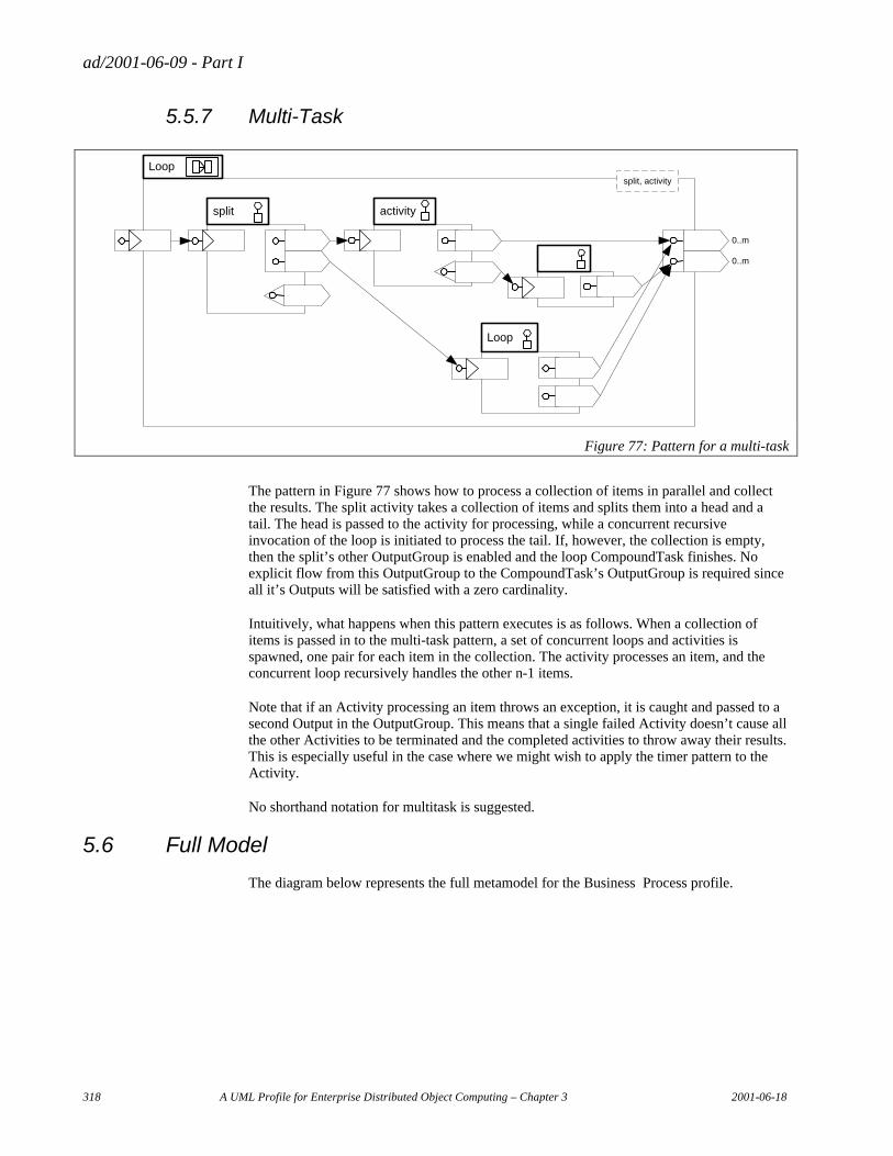
ad/2001-06-09 - Part I
318 A UML Profile for Enterprise Distributed Object Computing – Chapter 3 2001-06-18
5.5.7 Multi-Task
activity
Loopsplit, activity
Loop
0..m
split
0..m
Figure 77: Pattern for a multi-task
The pattern in Figure 77 shows how to process a collection of items in parallel and collect the results. The split activity takes a collection of items and splits them into a head and a tail. The head is passed to the activity for processing, while a concurrent recursive invocation of the loop is initiated to process the tail. If, however, the collection is empty, then the split’s other OutputGroup is enabled and the loop CompoundTask finishes. No explicit flow from this OutputGroup to the CompoundTask’s OutputGroup is required since all it’s Outputs will be satisfied with a zero cardinality.
Intuitively, what happens when this pattern executes is as follows. When a collection of items is passed in to the multi-task pattern, a set of concurrent loops and activities is spawned, one pair for each item in the collection. The activity processes an item, and the concurrent loop recursively handles the other n-1 items.
Note that if an Activity processing an item throws an exception, it is caught and passed to a second Output in the OutputGroup. This means that a single failed Activity doesn’t cause all the other Activities to be terminated and the completed activities to throw away their results. This is especially useful in the case where we might wish to apply the timer pattern to the Activity.
No shorthand notation for multitask is suggested.
5.6 Full Model
The diagram below represents the full metamodel for the Business Process profile.
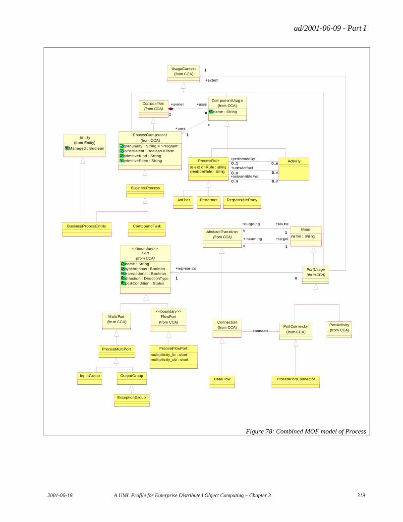
ad/2001-06-09 - Part I
2001-06-18 A UML Profile for Enterprise Distributed Object Computing – Chapter 3 319
Composition
(from CCA)
Com pon en tUsag e
name : String
(from CCA)
n1
+uses
n
+owner
1
ProcessCompo nen t
granularity : String = "Program"isPersistent : Boolean = falseprimitiveKind : StringprimitiveSpec : String
(from CCA)
n
1
n+uses
1
PortCon ne cto r
(from CCA)
PortActivity
(from CCA)
Multi Port
(from CCA)
FlowPort
(from CCA)
<<boundary>>
Port
name : Stringsynchronous : Booleantransactional : Booleandirection : DirectionTypepostCondition : Status
(from CCA)
<<boundary>>
UsageContext
(from CCA)
PortUsage
(fro m CCA)1 n
+represe nts
1 n
1
+extent
1
Abst ractTran sit ion
(from CCA)
Node
na me : Stri ng
n 1
+outgoing
n
+sou rce
1
n 1
+incoming
n
+target
1
ProcessPortConnector
ProcessFlowPort
multiplicity_lb : shortmultiplicity_ub : short
ProcessMultiPort
InputGroup OutputGroup
ExceptionGroup
DataFlow
BusinessProcess
CompoundTask
ProcessRole
sele cti onRule : stringcreationRule : string
Activi ty
0..n 0..n+responsibleFor0..n 0..n
0..n 0..n+usesArtifact
0..n 0..n
0..1 0..n+performedBy0..1 0..n
Connection
(from CCA)connects
BusinessProcessEntity
Enti ty
Managed : Boolean
(from Entity)
Arti fac t Performer ResponsibleParty
Figure 78: Combined MOF model of Process
ad/2001-06-09 - Part I
320 A UML Profile for Enterprise Distributed Object Computing – Chapter 3 2001-06-18
6. The Relationships Profile
The Relationships profile describes the extensions to the UML core facilities to meet the need for rigorous relationship specification in general and in business modeling and software modeling in particular.
6.1 Requirements
6.1.1 Introduction
This section describes extensions to the UML core facilities that support the need for rigorous relationship specification in general and in business modeling and software modeling in particular. In this context, the most important and most interesting aspects of behavior are in the relationships between participants rather than in the behavior of participants1. Therefore clear, concise and rigorous specification of relationship semantics is of utmost importance.
Note that multiplicities are not the most important or most interesting properties of relationships2. Property determinations are much more important for the semantics of a relationship, and distinguish among different kinds of relationships. The fragments of relationship invariants about property determination represent an essential fragment of those elusive “business rules” that are the backbone of a good specification and that should never be only “in the code.”
At the same time, it is very desirable to discover and specify – rather than reinvent – those kinds of relationships that are encountered in all specifications, so that reuse at the specification level becomes possible. Such generic relationships extend the set of reusable constructs that already exist in UML.
This section includes somewhat simplified examples that demonstrate the practical usage of these relationships.
The section also provides advice for choosing and using a subset of UML for business modeling such a that the business models represented in terms of this subset will be readable and understandable by all stakeholders, specifically, business subject matter experts, analysts, and developers (as well as managers). The generic relationships described here are among the most important constructs of this subset.
The UML extensions described in this document were not invented from scratch; they were reused from existing international standards and based on existing modeling practice. The material about generic relationships presented here is based on long-term experience in modeling in various areas (telecommunications, finance, insurance, document management, business process change, etc) described in [12], [10], [14], [17] and elsewhere.
1“Behavior must be described at the system level, not the object level: all interesting behavior is in the relationships between objects, and it is impossible to understand behavior of the system by looking only at the behavior of its parts.” (From the keynote of Anthony Hall at Requirements Engineering’97) 2 In most cases, the multiplicities follow from the generic relationship invariant and therefore do not need to be explicitly shown in the diagram: the Stereotype takes care of that. Such diagrams are less cluttered.
ad/2001-06-09 - Part I
2001-06-18 A UML Profile for Enterprise Distributed Object Computing – Chapter 3 321
Similarly to UML, we use invariants to specify the semantics of various kinds of relationships. UML 1.4 Section 2.3.2 states, “The static semantics ... are defined as a set of invariants of an instance of the [association].... These invariants have to be satisfied for the construct to be meaningful.”.
The approach presented here is extensible, and if it appears that in a particular business (or a set of applications) additional generic relationships are needed and useful, then they may be precisely and explicitly defined and added in a manner similar to the definitions provided here.
Generic relationships provide concepts and constructs that permit UML to be used for specification of businesses and systems in a more rigorous manner than (and without restrictions currently imposed by) the base UML 1.4. Generic relationships provide for explicit specification of relationship semantics in class diagrams, so that a line between boxes – even a named line! – will not be considered an adequate relationship specification.3 Names by themselves do not determine semantics; if a name is used then it has to be precisely defined in the same manner that generic relationship stereotype names like “Assembly” are defined in this document4.
The semantics of a class diagram is in its structure – the collections of “lines” – and so it has to be appropriately defined and represented graphically. Fortunately, UML provides adequate extension facilities to satisfy this goal.
6.1.2 Non-Binary Relationships
In many cases, a relationship – such as subtyping or UML aggregation – is defined between more than two participants. This happens because the invariant that defines the relationship refers to all its participants rather than just to two of them. Therefore, several binary relationships are not equivalent to one non-binary. The joint properties of these binary relationships (formalized in the invariant referring to all of them) would not be specified in the former case. More specifically, such invariants often describe how the properties of one relationship participant – such as the “whole” – are determined on the basis of the (joint) properties of the other relationship participants – such as its “parts.”
Based on substantial modeling experience – see also the examples below – we consider most relationships to be asymmetric, and more specifically, we state that an asymmetric relationship relates5 a source type to a non-empty set of target types. As a familiar example, in a generic Aggregation relationship (which corresponds to the RM-ODP composition6), the “whole” is related to a “collection of parts,” and the specific invariant determines the kind of this relationship. In other words, only a collection of all AssociationEnds jointly realizes an Association.
As a more specific consequence, visible in Figure 79, we must clearly and explicitly distinguish between two or more aggregations for the same whole (which are not interrelated by any invariant) and a non-binary aggregation defined by a specific (property determination) invariant.
3 A combination of two interrelated lines required by the currently existing UML metamodel is an exception; specifically, an association line that simply mandates a link is acceptable, but only if it is paired with a <<Reference>> dependency line. <<Reference>> is defined later in this document. 4 After a precisely defined relationship was named, the name may be used again and again without repeating the semantics. Such a name may be used instead of the semantics (and vice versa). 5 This is based on the mathematical concept of a relation used in formal specifications; see, for example, [PST91]. 6 RM-ODP [RM-ODP] defines a composition of objects as follows: “A combination of two or more objects yielding a new object, at a different level of abstraction. The characteristics of the new object are determined by the objects being combined and by the way they are combined.” Similarly, other <X>s (such as behaviors) can be composed.
ad/2001-06-09 - Part I
322 A UML Profile for Enterprise Distributed Object Computing – Chapter 3 2001-06-18
Since UML version 1.4 requires an Aggregation to be binary only, we have to remove this restriction (e.g., from UML 1.4, Section 2.5.3, Rule 3; also, UML 1.4, Sections 3.3 and 3.43.3 are affected since an “aggregation tree” may have its own semantics and is not just a presentation option; etc.). After that, we can apply the “Aggregation” Stereotype and its subtypes to Association7 (note that the property determination invariant is explicitly used to define this Stereotype)
Appropriate icons — that can represent directionality — are essential for a better graphical representation. Clearly, there is no need to have an icon for every conceivable modeling element, but the already existing (asymmetric!) UML icons representing a relationship (e.g. diamond for aggregation or triangle for subtyping), together with a Stereotype abbreviating the invariant of the relationship type, solve the problem, as seen from the examples.
6.1.3 Example: Mutually Orthogonal Non-Binary Aggregations
Figure 79 demonstrates the need for non-binary aggregations, for different (mutually orthogonal) aggregations for the same whole, and for an asymmetric representation of non-binary relationships in general.
Currently, UML 1.4 restricts aggregations to being binary; this restriction does not permit clear representation of business requirements, specifically the invariants, like the ones shown in the example. Similarly, UML treats all parts for the same aggregate in an equal manner; this restriction does not permit grouping only those parts that “belong together” because those parts are referred to in the same aggregation invariant for property determination.
UML also does not currently specify how to show mutually orthogonal (independent) aggregations on a diagram. Such aggregations appear quite often, in particular when different viewpoints have to be considered8. Finally, the current UML represents non-binary associations in a way that does not clearly distinguish between association source and target. Such distinction is needed for non-binary Aggregation Associations.
The example shows how UML is extended to deal with these issues by using the generic relationships described in this document. The diagram below (see Figure 79) demonstrates two aggregations– a content-based and a logical layout-based decomposition of an OMG Domain Task Force (DTF) specification document.
7 This traditionally has been represented graphically as a “diamond” attached to the “whole”. Other representations are certainly possible. 8 Presenting (abstractions of) the different aggregations of the same whole in the same diagram provides a roadmap that enhances understanding of complex specifications. As a more specific example, four different ways to decompose a Trade were deemed necessary by the business experts in an exotic option environment.
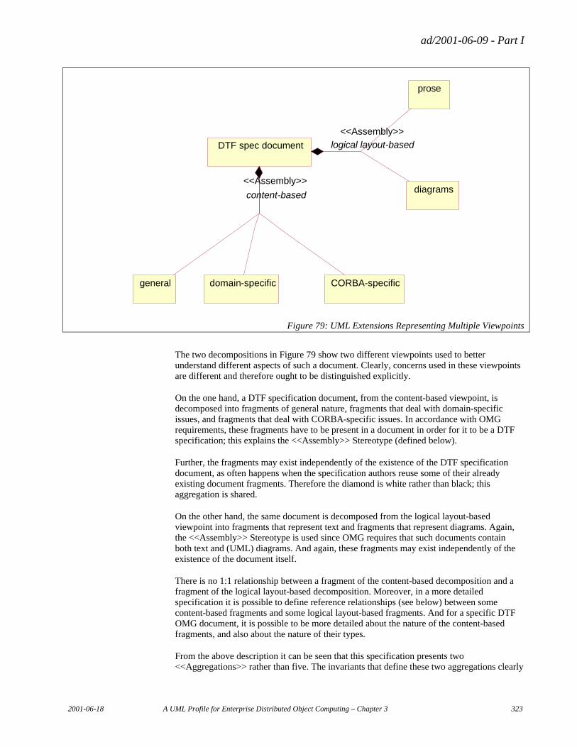
ad/2001-06-09 - Part I
2001-06-18 A UML Profile for Enterprise Distributed Object Computing – Chapter 3 323
general domain-specific CORBA-specific
prose
diagrams
DTF spec document
content-based
<<Assembly>>
logical layout-based <<Assembly>>
Figure 79: UML Extensions Representing Multiple Viewpoints
The two decompositions in Figure 79 show two different viewpoints used to better understand different aspects of such a document. Clearly, concerns used in these viewpoints are different and therefore ought to be distinguished explicitly.
On the one hand, a DTF specification document, from the content-based viewpoint, is decomposed into fragments of general nature, fragments that deal with domain-specific issues, and fragments that deal with CORBA-specific issues. In accordance with OMG requirements, these fragments have to be present in a document in order for it to be a DTF specification; this explains the <<Assembly>> Stereotype (defined below).
Further, the fragments may exist independently of the existence of the DTF specification document, as often happens when the specification authors reuse some of their already existing document fragments. Therefore the diamond is white rather than black; this aggregation is shared.
On the other hand, the same document is decomposed from the logical layout-based viewpoint into fragments that represent text and fragments that represent diagrams. Again, the <<Assembly>> Stereotype is used since OMG requires that such documents contain both text and (UML) diagrams. And again, these fragments may exist independently of the existence of the document itself.
There is no 1:1 relationship between a fragment of the content-based decomposition and a fragment of the logical layout-based decomposition. Moreover, in a more detailed specification it is possible to define reference relationships (see below) between some content-based fragments and some logical layout-based fragments. And for a specific DTF OMG document, it is possible to be more detailed about the nature of the content-based fragments, and also about the nature of their types.
From the above description it can be seen that this specification presents two <<Aggregations>> rather than five. The invariants that define these two aggregations clearly
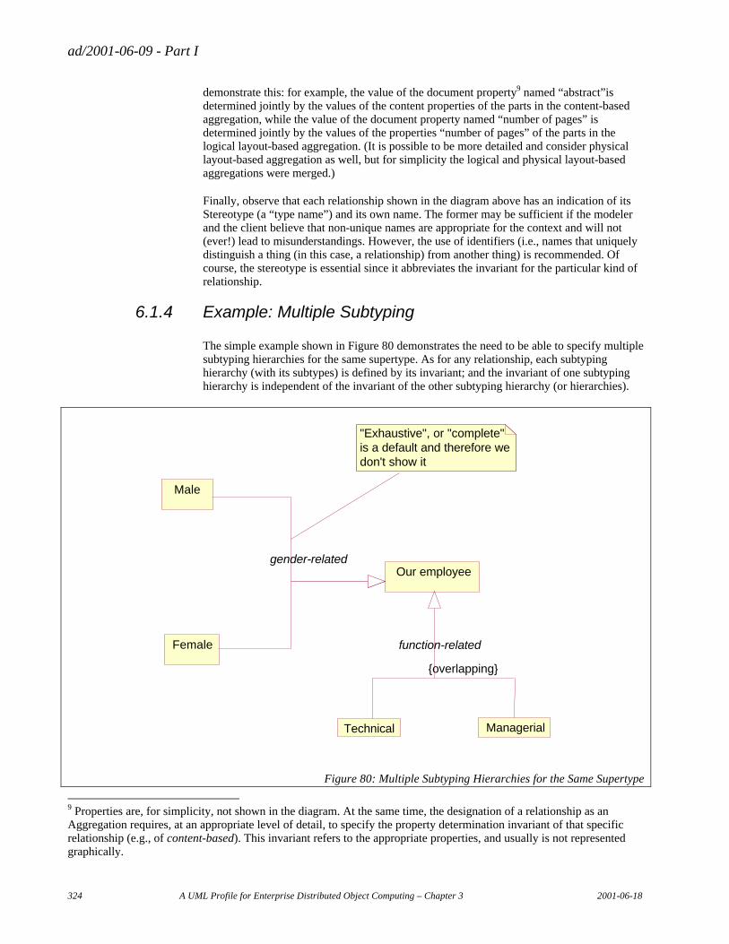
ad/2001-06-09 - Part I
324 A UML Profile for Enterprise Distributed Object Computing – Chapter 3 2001-06-18
demonstrate this: for example, the value of the document property9 named “abstract”is determined jointly by the values of the content properties of the parts in the content-based aggregation, while the value of the document property named “number of pages” is determined jointly by the values of the properties “number of pages” of the parts in the logical layout-based aggregation. (It is possible to be more detailed and consider physical layout-based aggregation as well, but for simplicity the logical and physical layout-based aggregations were merged.)
Finally, observe that each relationship shown in the diagram above has an indication of its Stereotype (a “type name”) and its own name. The former may be sufficient if the modeler and the client believe that non-unique names are appropriate for the context and will not (ever!) lead to misunderstandings. However, the use of identifiers (i.e., names that uniquely distinguish a thing (in this case, a relationship) from another thing) is recommended. Of course, the stereotype is essential since it abbreviates the invariant for the particular kind of relationship.
6.1.4 Example: Multiple Subtyping
The simple example shown in Figure 80 demonstrates the need to be able to specify multiple subtyping hierarchies for the same supertype. As for any relationship, each subtyping hierarchy (with its subtypes) is defined by its invariant; and the invariant of one subtyping hierarchy is independent of the invariant of the other subtyping hierarchy (or hierarchies).
Our employee
Male
Female
Technical Managerial
function-related
{overlapping}
gender-related
"Exhaustive", or "complete"is a default and therefore wedon't show it
Figure 80: Multiple Subtyping Hierarchies for the Same Supertype
9 Properties are, for simplicity, not shown in the diagram. At the same time, the designation of a relationship as an Aggregation requires, at an appropriate level of detail, to specify the property determination invariant of that specific relationship (e.g., of content-based). This invariant refers to the appropriate properties, and usually is not represented graphically.
ad/2001-06-09 - Part I
2001-06-18 A UML Profile for Enterprise Distributed Object Computing – Chapter 3 325
In this example, an employee satisfies exactly one subtype in the gender-related subtyping hierarchy and at least one subtype in the function-related subtyping hierarchy. Thus, the function-related subtyping is overlapping: the employee may satisfy either one or both subtypes in this hierarchy at the same time. Clearly, the two subtyping hierarchies presented above are mutually independent. It means that the four subtypes shown in the diagram cannot be merged into one subtyping hierarchy: such merge would destroy the semantics represented there.
6.1.5 Other Relationship Requirements
The following additional important generic relationships (and their subtypes) have been defined in [12] and elsewhere:
• Reference: A binary, asymmetric relationship in which the properties of instances of one type determine the properties of instances of another type.
6.2 Using UML to Address the Requirements: An Overview
Some of the required relationships can be represented in UML in a straightforward manner. UML 1.4 permits specification of multiple mutually independent (mutually orthogonal) subtyping hierarchies of the same supertype, as well as the specification of multiple subtypes of the same supertype in the same subtyping hierarchy10. This was demonstrated in the example above. In addition, some of the generic subtypes of composition may be presented using existing UML constructs (see below).
In UML a subtype hierarchy is called a partition11. A sub/supertype relationship is called a Generalization, which has one element in the role of parent and one in the role of child. A Generalization has a property called the discriminator. If two Generalizations have the same parent and the same discriminator, then they are part of the same partition.
A Generalization partition can be constrained to be complete or incomplete and, separately, to be disjoint or overlapping. If a partition is incomplete it means that there could conceivably be instances of the supertype that are not instances of any of the subtypes. Complete is the default. If a subtype hierarchy is disjoint it means that no instance of the supertype can be an instance of more than one of the subtypes. Disjoint is the default.
Therefore, in what follows, the generic subtyping relationship will not be discussed further (although its UML representation will be used in examples). The generic relationships for which UML extensions are presented include only aggregation, reference, and symmetric relationships. The representation of these generic relationships will be accomplished by extending the UML core elements “Association” and “Dependency.”
6.3 Formal Virtual Metamodel of the UML Extensions
A virtual metamodel (VMM) is a formal model of a package of extensions to the UML metamodel using UML’s own built-in extension mechanisms. UML’s primary extension mechanisms are Stereotypes and TaggedValues.
10 In this manner, it is possible to support the specification of dynamic typing, i.e., of a thing acquiring and losing type(s). A thing acquires a type when it acquires the properties (satisfies the invariant) of that type; and a thing loses a type when it loses the properties (no longer satisfies the invariant of) that type. As an example, consider a person acquiring and losing such types as employee, homeowner, stockholder, and so on. 11 Not to be confused with a “swim lane” partition in an activity graph
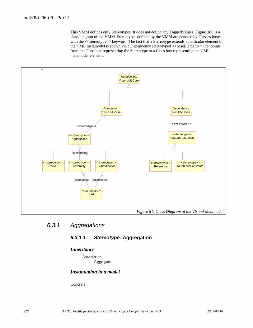
ad/2001-06-09 - Part I
326 A UML Profile for Enterprise Distributed Object Computing – Chapter 3 2001-06-18
This VMM defines only Stereotypes. It does not define any TaggedValues. Figure 100 is a class diagram of the VMM. Stereotypes defined by the VMM are denoted by Classes boxes with the <<stereotype>> keyword. The fact that a Stereotype extends a particular element of the UML metamodel is shown via a Dependency stereotyped <<baseElement>> that points from the Class box representing the Stereotype to a Class box representing the UML metamodel element.
_
Aggregation
_
<<stereotype>>
_
AbstractReference
_
<<stereotype>>
_ _ _
ReferenceForCreate
_
<<stereotype>>
_
Assembly
_
<<stereotype>>
_
Subordination
_
<<stereotype>>
_
List
_
<<stereotype>>
_
Dependency
_
(from UMLCore)
_
Association
_
(from UMLCore)
_
Relationship
_
(from UMLCore)
_
<<stereotype>>
_
<<stereotype>>
_
Packet
_
<<stereotype>>
_
{overlapping}
_
Reference
_
<<stereotype>>
_
{incomplete}
_
{incomplete}
_ _ _ _ _
Figure 81: Class Diagram of the Virtual Metamodel
6.3.1 Aggregations
6.3.1.1 Stereotype: Aggregation
Inheritance
Association Aggregation
Instantiation in a model
Concrete
ad/2001-06-09 - Part I
2001-06-18 A UML Profile for Enterprise Distributed Object Computing – Chapter 3 327
Semantics
For an Aggregation, the properties of one of the participants (of the source type) – also called the “whole” – are determined, in part, by the properties of the other participants – also called the “parts”.
The Aggregation properties captured by the Packet, Assembly, Subordination, and List Stereotypes described below are orthogonal to whether the aggregate's AggregationKind is shared (corresponding to shared Aggregation) or composite (corresponding to hierarchical Aggregation).
Tagged Values
None
Constraints
Constraints Expressed Generically
Invariant. An aggregate (“whole”) type corresponds to one or more part types, and an aggregate instance corresponds to zero or more instances of each part type. There exists at least one property of an aggregate instance determined by the properties of its part instances. There exists also at least one property of an aggregate instance independent of the properties of its part instances.
Note: It is not possible to express all the semantics of Aggregation specified in the Invariant above – including the property determination semantics – in a way that can be rendered in OCL nor in a structured English that maps to OCL12. The OCL constraints for Aggregation merely pin down the relationship of the Aggregation Stereotype to previously existing concepts about aggregation in the UML metamodel. On the other hand, the formal constraints for the sub-Stereotypes of Aggregation (Assembly, Subordination, etc.) in subsequent sections really do express the essential semantic distinctions that these more specific Stereotypes convey.
Formal Constraints Expressed in Terms of the UML Metamodel
English
Invariant: For exactly one of the participants in the Association, AggregationKind = shared or AggregationKind = composite.
OCL inv OneAggregate: self.connections->select (end | end.aggregation <> #none)
->size = 1
12 The UML specification makes no claim that all the semantics are expressed in OCL; it labels the OCL assertions only as well-formedness rules.
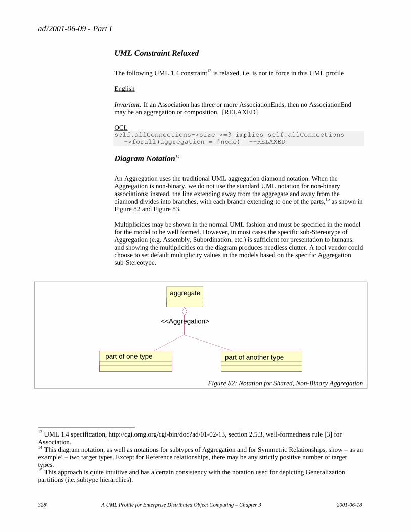
ad/2001-06-09 - Part I
328 A UML Profile for Enterprise Distributed Object Computing – Chapter 3 2001-06-18
UML Constraint Relaxed
The following UML 1.4 constraint13 is relaxed, i.e. is not in force in this UML profile
English
Invariant: If an Association has three or more AssociationEnds, then no AssociationEnd may be an aggregation or composition. [RELAXED]
OCL self.allConnections->size >=3 implies self.allConnections
->forall(aggregation = #none) --RELAXED
Diagram Notation14
An Aggregation uses the traditional UML aggregation diamond notation. When the Aggregation is non-binary, we do not use the standard UML notation for non-binary associations; instead, the line extending away from the aggregate and away from the diamond divides into branches, with each branch extending to one of the parts,15 as shown in Figure 82 and Figure 83.
Multiplicities may be shown in the normal UML fashion and must be specified in the model for the model to be well formed. However, in most cases the specific sub-Stereotype of Aggregation (e.g. Assembly, Subordination, etc.) is sufficient for presentation to humans, and showing the multiplicities on the diagram produces needless clutter. A tool vendor could choose to set default multiplicity values in the models based on the specific Aggregation sub-Stereotype.
part of one type part of another type
aggregate
<<Aggregation>
Figure 82: Notation for Shared, Non-Binary Aggregation
13 UML 1.4 specification, http://cgi.omg.org/cgi-bin/doc?ad/01-02-13, section 2.5.3, well-formedness rule [3] for Association. 14 This diagram notation, as well as notations for subtypes of Aggregation and for Symmetric Relationships, show – as an example! – two target types. Except for Reference relationships, there may be any strictly positive number of target types. 15 This approach is quite intuitive and has a certain consistency with the notation used for depicting Generalization partitions (i.e. subtype hierarchies).
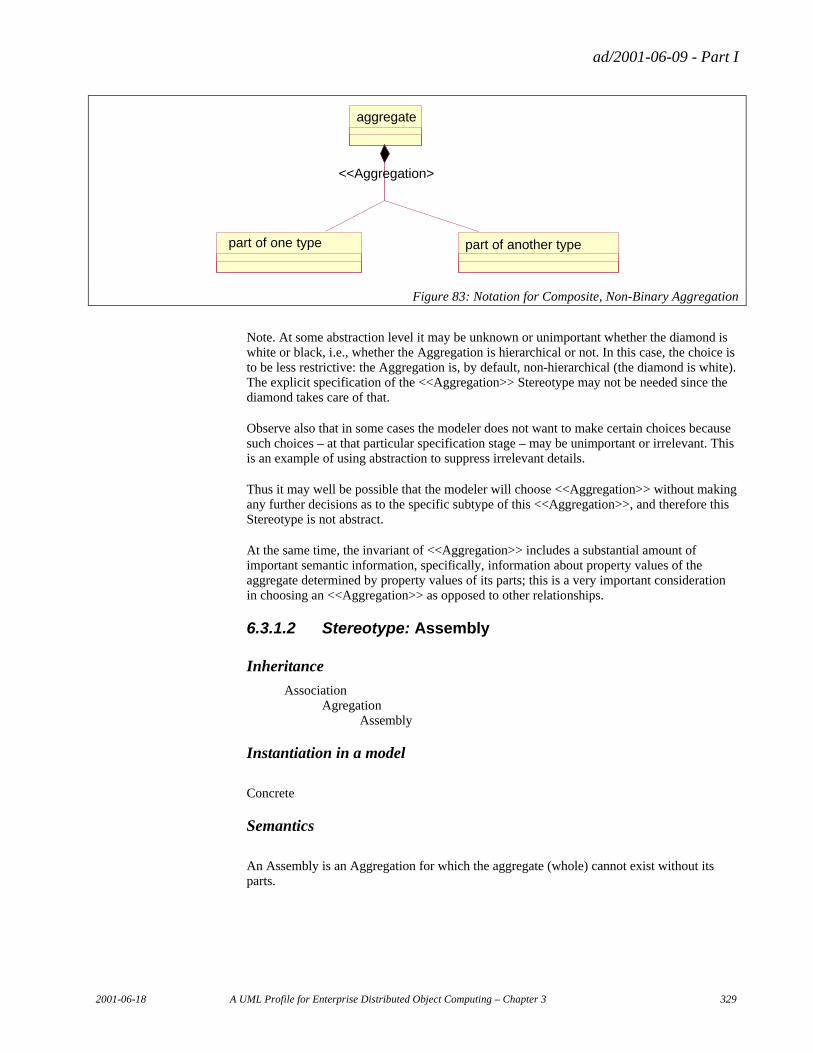
ad/2001-06-09 - Part I
2001-06-18 A UML Profile for Enterprise Distributed Object Computing – Chapter 3 329
part of one type part of another type
aggregate
<<Aggregation>
Figure 83: Notation for Composite, Non-Binary Aggregation
Note. At some abstraction level it may be unknown or unimportant whether the diamond is white or black, i.e., whether the Aggregation is hierarchical or not. In this case, the choice is to be less restrictive: the Aggregation is, by default, non-hierarchical (the diamond is white). The explicit specification of the <<Aggregation>> Stereotype may not be needed since the diamond takes care of that.
Observe also that in some cases the modeler does not want to make certain choices because such choices – at that particular specification stage – may be unimportant or irrelevant. This is an example of using abstraction to suppress irrelevant details.
Thus it may well be possible that the modeler will choose <<Aggregation>> without making any further decisions as to the specific subtype of this <<Aggregation>>, and therefore this Stereotype is not abstract.
At the same time, the invariant of <<Aggregation>> includes a substantial amount of important semantic information, specifically, information about property values of the aggregate determined by property values of its parts; this is a very important consideration in choosing an <<Aggregation>> as opposed to other relationships.
6.3.1.2 Stereotype: Assembly
Inheritance
Association Agregation Assembly
Instantiation in a model
Concrete
Semantics
An Assembly is an Aggregation for which the aggregate (whole) cannot exist without its parts.
ad/2001-06-09 - Part I
330 A UML Profile for Enterprise Distributed Object Computing – Chapter 3 2001-06-18
Tagged Values
None
Constraints
Constraints Expressed Generically
Invariant: The existence of an aggregate instance implies the existence of at least one corresponding part instance.
Formal Constraints Expressed in Terms of the UML Metamodel
English
Invariant: The multiplicity of the part ends of the association must have a lower bound of at least 1.
OCL inv PartMultiplicity: let parts= self.connections->select (end | end.aggregation
= #none) in parts->forAll (multiplicity.range->forAll (lower >= 1) )
Note: The sub-Stereotypes of Aggregation (Assembly, Subordination, etc.) essentially specify a set of multiplicity constraints. At first glance the UML-aware reader may conclude that these Stereotypes merely duplicate the ability to express multiplicity that UML already has and are therefore unnecessary. In order to understand the added value, one must consider non-binary Aggregations.
For example, the invariant of Assembly constrains the multiplicities on all of the part AssociationEnds in a non-binary Aggregation, and thus adds another level of validation that can be conducted as to whether a model is well formed. In addition, multiplicities in this context are realizations of the semantics specified in the appropriate invariants at a (somewhat) higher abstraction level preferable for human readers.
Diagram Notation
The notation for Aggregation is used (see Figure 82 and Figure 83), except that the Stereotype keyword is <<Assembly>>. Therefore the specific diagrams are not provided here.
6.3.1.3 Stereotype: Subordination
Inheritance
Association Aggregation Subordination
ad/2001-06-09 - Part I
2001-06-18 A UML Profile for Enterprise Distributed Object Computing – Chapter 3 331
Instantiation in a model
Concrete
Semantics
A Subordination is an Aggregation for which the parts cannot exist without their aggregate (whole).
Tagged Values
None
Constraints
Constraints Expressed Generically
Invariant: The existence of a part instance implies the existence of at least one corresponding aggregate instance.
Formal Constraints Expressed in Terms of the UML Metamodel
English
Invariant: The multiplicity of the aggregate end of the association must have a lower bound of at least 1.
OCL inv AggregateMultiplicity: let aggregate = self.connections->select (end |
end.aggregation <> #none) in aggregate.multiplicity.range ->forAll (lower >= 1)
Diagram Notation
The notation for Aggregation is used (see Figure 82 and Figure 83), except that the Stereotype keyword is <<Subordination>>. Therefore the specific diagrams are not provided here.
6.3.1.4 Stereotype: Packet
Inheritance
Association Aggregation Packet
Instantiation in a model
Concrete
ad/2001-06-09 - Part I
332 A UML Profile for Enterprise Distributed Object Computing – Chapter 3 2001-06-18
Semantics
A Packet is an Aggregation for which the parts can exist without their aggregate, and the aggregate can exist without its parts. This is the default for Aggregation.
Tagged Values
None
Constraints
No additional Constraints beyond those inherited from Aggregation.
Diagram Notation
The notation for Aggregation is used (see Figure 82 and Figure 83), except that the Stereotype keyword is <<Packet>>. Therefore the specific diagrams are not provided here.
6.3.1.5 Stereotype: List
Inheritance
Association Aggregation Assembly List Association Aggregation Subordination List
Instantiation in a model
Concrete
Semantics
A List is an Aggregation for which the parts cannot exist without their aggregate, and the aggregate cannot exist without its parts. Thus, a List is a subtype of both Assembly and Subordination; both subtypings are incomplete.
Tagged Values
None
Constraints
No additional Constraints beyond those inherited from Assembly and Subordination.
ad/2001-06-09 - Part I
2001-06-18 A UML Profile for Enterprise Distributed Object Computing – Chapter 3 333
Diagram Notation
The notation for Aggregation is used (see Figure 82 and Figure 83), except that the Stereotype keyword is <<Packet>>. Therefore the specific diagrams are not provided here.
6.3.1.6 Special Notes on Shared and Composite Aggregations
As mentioned above, any of the forms of Aggregation defined here can be used with either shared or composite aggregation (also known as weak and strong aggregation, respectively). Sometimes it is helpful to think of shared and composite aggregations as non-hierarchical and hierarchical aggregations, respectively.
In UML the aggregate in a composite aggregation is allowed to have multiplicity of either 1..1 or 0..1, although many modelers are under the misconception that composite aggregation implies a multiplicity of 1..1 for the aggregate.
A composite aggregation stereotyped as a <<Subordination>> constrains the aggregate’s multiplicity to 1..1. Similarly, in UML the aggregate in a shared aggregation is allowed to have multiplicity of either 1..* or 0..*. A shared aggregation stereotyped as a <<Subordination>> constrains the aggregate’s multiplicity to 1..*.
6.3.2 Reference Relationships
6.3.2.1 Stereotype: AbstractReference
Inheritance
Dependency AbstractReference
Instantiation in a model
Abstract
Semantics
The property values of one participant – the maintained – are determined, in part, by the property values of the other participant – the referenced. The maintained and referenced participants are the client and supplier, respectively, in the UML Dependency relationship. AbstractReference is specialized into Reference and ReferenceForCreate, as shown below.
Tagged Values
None
ad/2001-06-09 - Part I
334 A UML Profile for Enterprise Distributed Object Computing – Chapter 3 2001-06-18
Constraints
Constraints Expressed Generically
Invariant: The existence of a maintained instance implies that if a corresponding instance of the reference type exists, then some property values of the instance of the maintained element are determined by some property values of the corresponding instance of the referenced element.
Formal Constraints Expressed in Terms of the UML Metamodel
It is not possible to express the constraints formally in terms of the UML metamodel.16
Diagram Notation
Since AbstractReference is abstract, no notation is defined for it. However, notation is defined for its sub-Stereotypes.
6.3.2.2 Stereotype: Reference
Inheritance
Dependency AbstractReference
Instantiation in a model
Concrete
Semantics
A Reference is the most common form of AbstractReference for which the property values of the maintained instance are determined, in part, by the current property values of the referenced instance.
Tagged Values
None
Constraints
Constraints Expressed Generically
Invariant: The property values of the maintained instance are determined, in part, by the current property values of the referenced instance. The property values of the client must
16 However, it is possible to define an implementation mapping. See notes in the sections on Reference and ReferenceForCreate below.
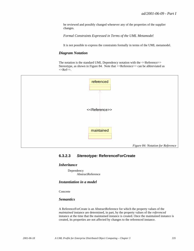
ad/2001-06-09 - Part I
2001-06-18 A UML Profile for Enterprise Distributed Object Computing – Chapter 3 335
be reviewed and possibly changed whenever any of the properties of the supplier changes.
Formal Constraints Expressed in Terms of the UML Metamodel
It is not possible to express the constraints formally in terms of the UML metamodel.
Diagram Notation
The notation is the standard UML Dependency notation with the <<Reference>> Stereotype, as shown in Figure 84. Note that <<Reference>> can be abbreviated as <<Ref>>.
referenced
maintained
<<Reference>>
Figure 84: Notation for Reference
6.3.2.3 Stereotype: ReferenceForCreate
Inheritance
Dependency AbstractReference
Instantiation in a model
Concrete
Semantics
A ReferenceForCreate is an AbstractReference for which the property values of the maintained instance are determined, in part, by the property values of the referenced instance at the time that the maintained instance is created. Once the maintained instance is created, its properties are not affected by changes to the referenced instance.
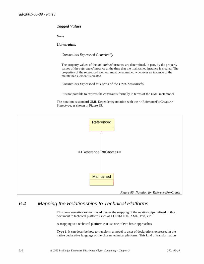
ad/2001-06-09 - Part I
336 A UML Profile for Enterprise Distributed Object Computing – Chapter 3 2001-06-18
Tagged Values
None
Constraints
Constraints Expressed Generically
The property values of the maintained instance are determined, in part, by the property values of the referenced instance at the time that the maintained instance is created. The properties of the referenced element must be examined whenever an instance of the maintained element is created.
Constraints Expressed in Terms of the UML Metamodel
It is not possible to express the constraints formally in terms of the UML metamodel.
The notation is standard UML Dependency notation with the <<ReferenceForCreate>> Stereotype, as shown in Figure 85.
Referenced
Maintained
<<ReferenceForCreate>>
Figure 85: Notation for ReferenceForCreate
6.4 Mapping the Relationships to Technical Platforms
This non-normative subsection addresses the mapping of the relationships defined in this document to technical platforms such as CORBA IDL, XML, Java, etc.
A mapping to a technical platform can use one of two basic approaches:
Type 1. It can describe how to transform a model to a set of declarations expressed in the native declarative language of the chosen technical platform. This kind of transformation
ad/2001-06-09 - Part I
2001-06-18 A UML Profile for Enterprise Distributed Object Computing – Chapter 3 337
targeted to the CORBA platform generates declarations expressed in CORBA IDL, i.e. CORBA interfaces, valuetypes, etc. If targeted to the Java platform, it generates declarative Java code, i.e. Java interfaces and abstract classes. If targeted to XML, it generates an XML DTD or XML Schema, both of which are essentially declarative code.
Type 2. It can describe how transform a model to another UML model expressed in terms of a UML profile targeted to the chosen technical platform, such as the UML Profile for CORBA17 or the UML Profile for EJB18. Such UML profiles support expression via UML of declarative semantics in terms of the concepts native to the chosen technical platform.
Within the scope of this mapping section (section 6.4), we refer to these two types of mappings as Type 1 and Type 2 mappings.
6.4.1 Aggregations
6.4.1.1 Decomposing Non-Binary Aggregations
Any Type 1 or Type 2 mapping algorithm that covers the transformation of UML 1.4 binary aggregation associations can be applied in a straightforward manner to the transformation of non-binary aggregations. Prior to executing the transformation, all non-binary aggregations should be decomposed into binary aggregations. The rules for decomposition are as follows:
• The participant classifier (i.e. the type) of the aggregate end of the non-binary aggregation becomes the participant classifier on the aggregate end of all of the binary aggregations resulting from the decomposition.
− The properties (such as name and multiplicity) of the aggregate end of each of the resulting binary aggregations are the same as the properties of the aggregate end of the non-binary aggregation. There is one exception to this rule:
− Typically the name of the aggregate end of each of the binary aggregations is the same as the name of the aggregate end of the non-binary aggregation, as illustrated by Figure 86. The exception case is where more than one of the aggregee ends of the non-binary aggregation have the same participant classifier, as in Figure 87, where Z is the participant classifier for two aggregee ends of the non-binary aggregation. In that case, there would be a name conflict if the aggregate end of both of the resulting non-binary aggregations had the same name (e.g. if both of the aggregate ends opposite Z in Figure 87 were named “a”). The rule for disambiguating the aggregate end names is to prepend the name with the name of the aggregee end. Thus in Figure 87, “z2” and “z” are prepended to the names of the respective aggregate ends of the binary aggregations.
• The participant classifier of the aggregee ends of the non-binary aggregation become the respective participant classifiers of the aggregee ends of the resulting binary aggregations.
− The properties of the aggregee end of each of the resulting binary aggregations are the same as the properties of the corresponding aggregee ends of the non-binary aggregation.
17 [UML-CORBA] 18 [JSR-40]
ad/2001-06-09 - Part I
338 A UML Profile for Enterprise Distributed Object Computing – Chapter 3 2001-06-18
6.4.1.2 Ignoring Aggregation Sub(stereo)types
Type 1 and Type 2 mapping algorithms should ignore all of the specific aggregation stereotypes defined in this profile that modify the a binary or non-binary aggregation (Assembly, Subordination, List, and Packet). These specific stereotypes are merely constraints on the multiplicities of the association ends. Any mapping of standard UML 1.4 aggregation associations would have to have rules for how the transformation is affected by these multiplicities. The presence of the stereotypes does not mean that these multiplicities are missing. Therefore the multiplicities can drive the transformation and the stereotypes are redundant.
6.4.1.3 Leveraging General Mappings
With these rules in hand, well-defined mappings such as the MOF-IDL19, MOF-XML (i.e. XMI)20, and MOF-Java21 mappings can be readily applied to the kind of binary and non-binary aggregations associations supported by this relationship profile. Since these well-defined mappings specify how to transform MOF models, some slight adjustments are necessary to apply them to UML models. The adjustments are quite minor and are necessitated by the slight degree to which the MOF and UML are out of sync with each other, a misalignment that is slated to be fixed by the UML 2.0 Infrastructure RFP process.
As an alternative to using MOF technology mappings, UML technology mappings can be leveraged as well. There are currently no standardized UML technology mappings, but a number of tools have defined their own proprietary mappings. Again, by applying the rules for decomposing non-binary aggregations it is straightforward to leverage such mappings.
19 [MOF 1.3] 20 [XMI 1.1] 21 [JSR-40]
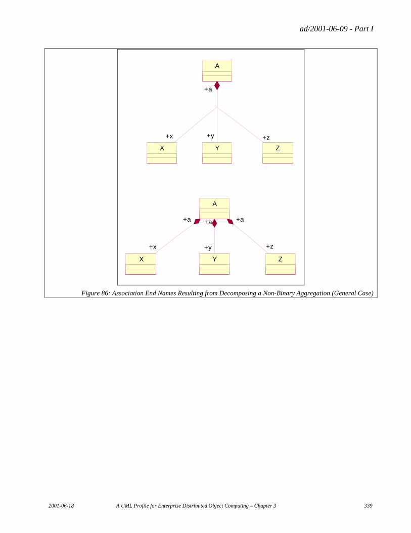
ad/2001-06-09 - Part I
2001-06-18 A UML Profile for Enterprise Distributed Object Computing – Chapter 3 339
X Z
A
Y
+a
+x +y +z
X Y Z
A
+x +y +z
+a +a +a
Figure 86: Association End Names Resulting from Decomposing a Non-Binary Aggregation (General Case)
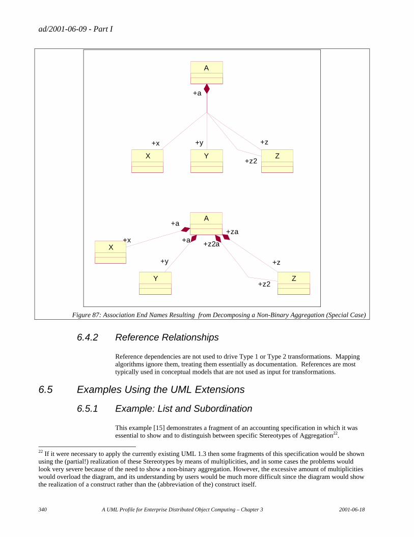
ad/2001-06-09 - Part I
340 A UML Profile for Enterprise Distributed Object Computing – Chapter 3 2001-06-18
X Y
A
+x +y
+a
Z
+z
+z2
X
Y Z
A
+x
+y +z
+z2
+a
+a+za
+z2a
Figure 87: Association End Names Resulting from Decomposing a Non-Binary Aggregation (Special Case)
6.4.2 Reference Relationships
Reference dependencies are not used to drive Type 1 or Type 2 transformations. Mapping algorithms ignore them, treating them essentially as documentation. References are most typically used in conceptual models that are not used as input for transformations.
6.5 Examples Using the UML Extensions
6.5.1 Example: List and Subordination
This example [15] demonstrates a fragment of an accounting specification in which it was essential to show and to distinguish between specific Stereotypes of Aggregation22.
22 If it were necessary to apply the currently existing UML 1.3 then some fragments of this specification would be shown using the (partial!) realization of these Stereotypes by means of multiplicities, and in some cases the problems would look very severe because of the need to show a non-binary aggregation. However, the excessive amount of multiplicities would overload the diagram, and its understanding by users would be much more difficult since the diagram would show the realization of a construct rather than the (abbreviation of the) construct itself.
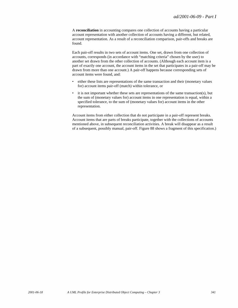
ad/2001-06-09 - Part I
2001-06-18 A UML Profile for Enterprise Distributed Object Computing – Chapter 3 341
A reconciliation in accounting compares one collection of accounts having a particular account representation with another collection of accounts having a different, but related, account representation. As a result of a reconciliation comparison, pair-offs and breaks are found.
Each pair-off results in two sets of account items. One set, drawn from one collection of accounts, corresponds (in accordance with “matching criteria” chosen by the user) to another set drawn from the other collection of accounts. (Although each account item is a part of exactly one account, the account items in the set that participates in a pair-off may be drawn from more than one account.) A pair-off happens because corresponding sets of account items were found, and:
• either these lists are representations of the same transaction and their (monetary values for) account items pair-off (match) within tolerance, or
• it is not important whether these sets are representations of the same transaction(s), but the sum of (monetary values for) account items in one representation is equal, within a specified tolerance, to the sum of (monetary values for) account items in the other representation.
Account items from either collection that do not participate in a pair-off represent breaks. Account items that are parts of breaks participate, together with the collections of accounts mentioned above, in subsequent reconciliation activities. A break will disappear as a result of a subsequent, possibly manual, pair-off. Figure 88 shows a fragment of this specification.)
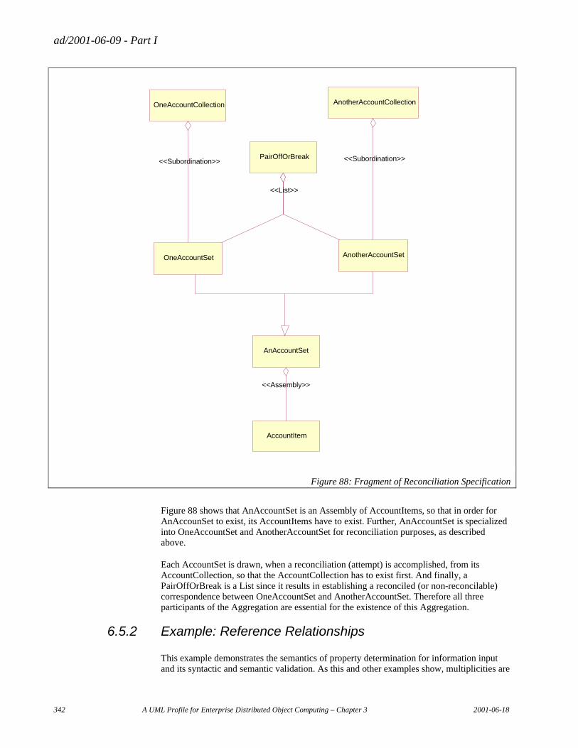
ad/2001-06-09 - Part I
342 A UML Profile for Enterprise Distributed Object Computing – Chapter 3 2001-06-18
PairOffOrBreak
OneAccountCollection
OneAccountSet
AnotherAccountCollection
AnotherAccountSet
<<List>>
<<Subordination>> <<Subordination>>
AnAccountSet
AccountItem
<<Assembly>>
Figure 88: Fragment of Reconciliation Specification
Figure 88 shows that AnAccountSet is an Assembly of AccountItems, so that in order for AnAccounSet to exist, its AccountItems have to exist. Further, AnAccountSet is specialized into OneAccountSet and AnotherAccountSet for reconciliation purposes, as described above.
Each AccountSet is drawn, when a reconciliation (attempt) is accomplished, from its AccountCollection, so that the AccountCollection has to exist first. And finally, a PairOffOrBreak is a List since it results in establishing a reconciled (or non-reconcilable) correspondence between OneAccountSet and AnotherAccountSet. Therefore all three participants of the Aggregation are essential for the existence of this Aggregation.
6.5.2 Example: Reference Relationships
This example demonstrates the semantics of property determination for information input and its syntactic and semantic validation. As this and other examples show, multiplicities are
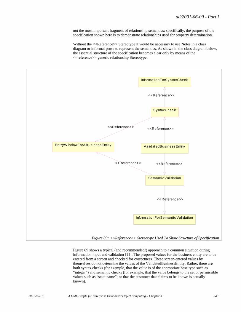
ad/2001-06-09 - Part I
2001-06-18 A UML Profile for Enterprise Distributed Object Computing – Chapter 3 343
not the most important fragment of relationship semantics; specifically, the purpose of the specification shown here is to demonstrate relationships used for property determination.
Without the <<Reference>> Stereotype it would be necessary to use Notes in a class diagram or informal prose to represent the semantics. As shown in the class diagram below, the essential structure of the specification becomes clear only by means of the <<reference>> generic relationship Stereotype.
InformationForSyntaxCheck
SyntaxChec k
Validat edBusinessEnti tyEntryW indowForABusinessEntity
SemanticValidat ion
Info rm ationForSemantic Validation
<<Reference>>
<<Reference>>
<<Reference>>
<<Reference>> <<Reference>>
<<Reference>>
Figure 89: <<Reference>> Stereotype Used To Show Structure of Specification
Figure 89 shows a typical (and recommended!) approach to a common situation during information input and validation [11]. The proposed values for the business entity are to be entered from a screen and checked for correctness. These screen-entered values by themselves do not determine the values of the ValidatedBusinessEntity. Rather, there are both syntax checks (for example, that the value is of the appropriate base type such as “integer”) and semantic checks (for example, that the value belongs to the set of permissible values such as “state name”; or that the customer that claims to be known is actually known).

ad/2001-06-09 - Part I
344 A UML Profile for Enterprise Distributed Object Computing – Chapter 3 2001-06-18
Business rules are specified for the SyntaxCheck and for the SemanticValidation. Each business rule, as a maintained entity, has two reference relationships – pointing to the EntryWindowForABusinessEntity and to the InformationForValidation – since the properties of the business rule will be determined, in part, by the properties of two of its reference entities. Similarly, the ValidatedBusinessEntity has two reference relationships pointing to these two business rules since the properties of the ValidatedBusinessEntity will be determined, in part, by the properties of these rules.
Clearly, the specific property determination invariants will have to be provided explicitly in the specification of each of these reference relationships. The diagram indicates that these relationships exist and that such invariants are to be provided – otherwise the specification is incomplete. If these invariants are simple enough then they may also be represented as Notes in the diagram.
ad/2001-06-09 - Part I
2001-06-18 A UML Profile for Enterprise Distributed Object Computing – Chapter 4 345
Chapter 4 The Patterns Profile
Table of Contents
1. Rationale ....................................................................................................................................................... 346 1.1 Introduction .......................................................................................................................................... 346 1.2 Pattern Principle ................................................................................................................................... 347 1.3 Notation for Pattern .............................................................................................................................. 348 1.4 Simple Pattern ...................................................................................................................................... 350 1.5 Pattern Inheritance................................................................................................................................ 350 1.6 Pattern Composition ............................................................................................................................. 351 1.7 Summary of Pattern Formats ................................................................................................................ 352 1.8 Applying Patterns ................................................................................................................................. 352
2. Patterns Metamodel....................................................................................................................................... 354 2.1 EDOC::Pattern Package ....................................................................................................................... 355
2.1.1 Business Pattern Name................................................................................................................ 355 2.1.2 Business Pattern Package............................................................................................................ 356 2.1.3 Business Pattern Binding ............................................................................................................ 357
3. UML Profile .................................................................................................................................................. 359 3.1 Table mapping concepts to profile elements ........................................................................................ 359 3.2 Introduction .......................................................................................................................................... 359 3.3 Pattern Package .................................................................................................................................... 360
3.3.1 BP Name ..................................................................................................................................... 360 3.3.2 BP Package ................................................................................................................................. 360 3.3.3 BP Binding.................................................................................................................................. 362
ad/2001-06-09 - Part I
346 A UML Profile for Enterprise Distributed Object Computing – Chapter 4 2001-06-18
1. Rationale
1.1 Introduction
The proposed UML Profile for EDOC is designed to provide standard means, Business Function Object Patterns (BFOP), for expressing object models using UML package notation together with the mechanisms for applying patterns that are required to describe models.
Successful implementation of an enterprise computing system requires that the system operation to be directly related to the business processes it supports. Reusable standard models are required in order to build good object models for EDOC systems.
Standard models have Business Entities Objects, Business Processes Objects, Business Event Objects and Business Rules Objects of ECA. They also include a set of common and reusable patterns of relationship properties that occur in business modeling. BFOP is being developed to achieve this objective.
BFOP is a set of object patterns laid out in a hierarchical multi-layer structure, the Basic, Unit, Basic Model, Product (application systems) and Option layers.
Figure 90 illustrates how “Sales/Purchase Pattern” is composed from “Sales Order & Purchase Order Pattern”, “Closing Pattern” and so on. The UML parameterized collaboration mechanism is used to materialize the pattern integration.
One of the major benefits for using this multi-layered structure is that it enables reuse (inheritance) of the constraints which have been defined and encapsulated in patterns in the layers. It provides a normalized way to define constraints and is effective in maintaining consistency within the object model.
The proposed notion of Business Pattern Package (BP Package) defining a pattern and Business Pattern Binding (BP Binding) applying a pattern has the features of pattern inheritance and pattern composition. This capability is useful for expressing patterns that include the objects constructed by recursive component composition of ECA.
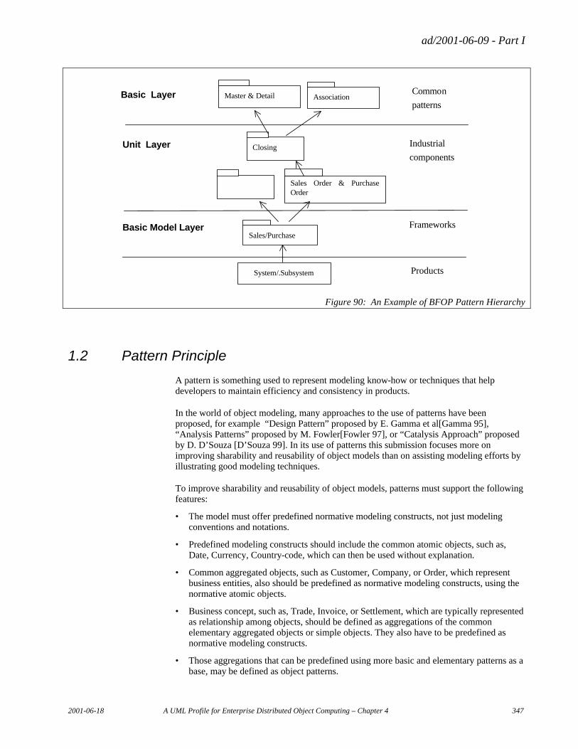
ad/2001-06-09 - Part I
2001-06-18 A UML Profile for Enterprise Distributed Object Computing – Chapter 4 347
Basic Layer Master & Detail Association
Unit Layer
Basic Model Layer
Closing
Sales Order & Purchase Order
Sales/Purchase
System/.Subsystem
Common
patterns
Industrial
components
Frameworks
Products
Figure 90: An Example of BFOP Pattern Hierarchy
1.2 Pattern Principle
A pattern is something used to represent modeling know-how or techniques that help developers to maintain efficiency and consistency in products.
In the world of object modeling, many approaches to the use of patterns have been proposed, for example “Design Pattern” proposed by E. Gamma et al[Gamma 95], “Analysis Patterns” proposed by M. Fowler[Fowler 97], or “Catalysis Approach” proposed by D. D’Souza [D’Souza 99]. In its use of patterns this submission focuses more on improving sharability and reusability of object models than on assisting modeling efforts by illustrating good modeling techniques.
To improve sharability and reusability of object models, patterns must support the following features:
• The model must offer predefined normative modeling constructs, not just modeling conventions and notations.
• Predefined modeling constructs should include the common atomic objects, such as, Date, Currency, Country-code, which can then be used without explanation.
• Common aggregated objects, such as Customer, Company, or Order, which represent business entities, also should be predefined as normative modeling constructs, using the normative atomic objects.
• Business concept, such as, Trade, Invoice, or Settlement, which are typically represented as relationship among objects, should be defined as aggregations of the common elementary aggregated objects or simple objects. They also have to be predefined as normative modeling constructs.
• Those aggregations that can be predefined using more basic and elementary patterns as a base, may be defined as object patterns.
ad/2001-06-09 - Part I
348 A UML Profile for Enterprise Distributed Object Computing – Chapter 4 2001-06-18
• Patterns can represent a business concept where they provide for aggregation of more elementary patterns. Therefore, the aggregation or composition mechanism is an essential element of patterns.
•
1.3 Notation for Pattern
Business rules that govern a business concept can be represented with a pattern with constraints encapsulated in it. Thus, the mechanism for constraint inheritance among patterns must be provided.
In this section, the concept and format of patterns are discussed from the viewpoint of pattern notation, relationships among patterns and pattern types and their instances.
We considered that there are three basic forms on expressing patterns. First, the simple pattern which is a pattern consisting of minimal elements needed to form a pattern. Second, the inherited pattern which is a pattern defined by inheriting from another pattern. And the third is the composite pattern which is a pattern defined as a result of combining more than two patterns. The composite pattern concept is an extension of the inherited pattern. Using the above three basic pattern forms as the base, we propose the following notations for expressing patterns and their metamodel.
It is important to consider the issue of type and its instantiation from the metamodel viewpoint. A pattern is a set of types that can be instantiated to create object models. A pattern for a set of object models is created by identifying and defining the common types among those object models, using a metamodel such as in the ECA profiles. Identifying and specifying many reusable business object patterns is useful for quick and high quality model development that can be attained by selecting appropriate patterns among various ones to use in the project as a template.
The instantiation of a composite pattern in a hierarchical structure becomes possible by resolving pattern inheritance and collaboration by "unfolding". When a composite pattern is granular enough to include implementation details, and it is possible to use it to describe a component concept such as CCA, each pattern package can be implemented with real components instead of unfolding it into a component pattern. In short, the proposed pattern concept and mechanism can be applied to the components based development that is required in EDOC.
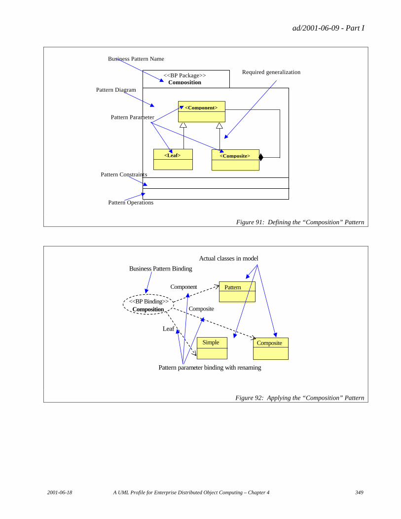
ad/2001-06-09 - Part I
2001-06-18 A UML Profile for Enterprise Distributed Object Computing – Chapter 4 349
Pattern Constraints
Pattern Parameter
Pattern Diagram
Pattern Operations
<Composite>
<Leaf>
<Component>
<<BP Package>> Composition
Business Pattern Name
Required generalization
Figure 91: Defining the “Composition” Pattern
Pattern
Simple Composite
Composition
Leaf
Actual classes in model
Business Pattern Binding
Pattern parameter binding with renaming
Component
Composite <<BP Binding>>
Figure 92: Applying the “Composition” Pattern
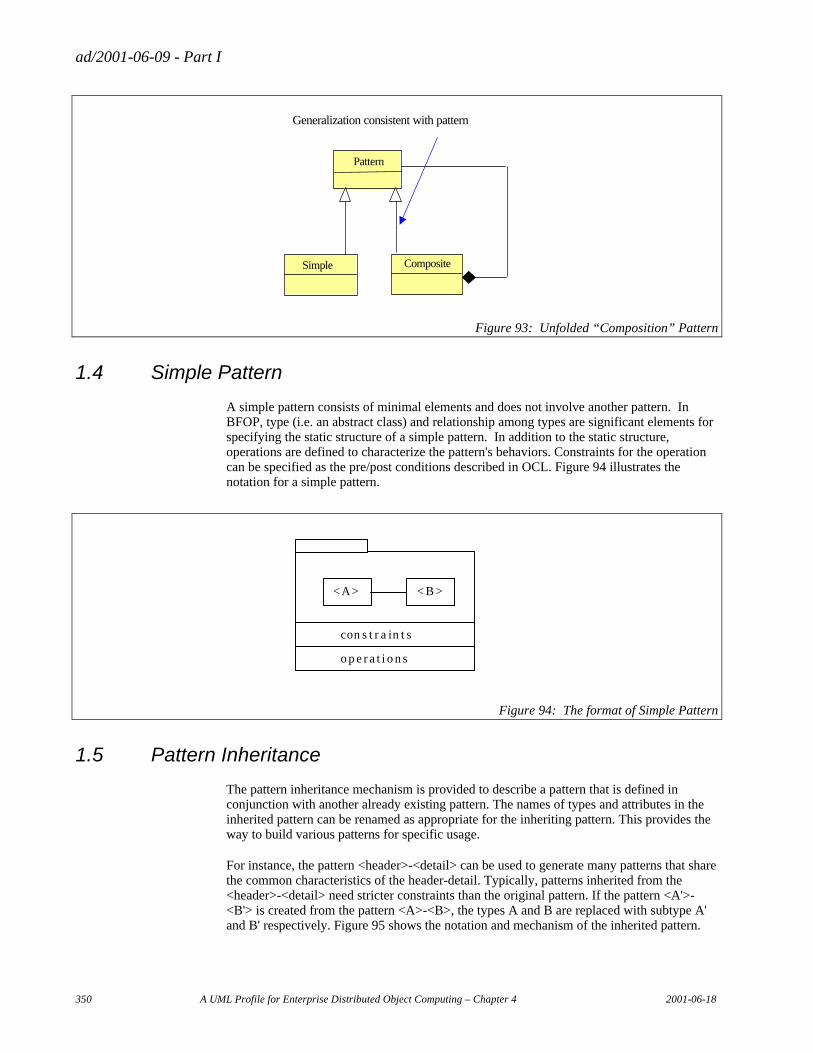
ad/2001-06-09 - Part I
350 A UML Profile for Enterprise Distributed Object Computing – Chapter 4 2001-06-18
Generalization consistent with pattern
Pattern
Simple Composite
Figure 93: Unfolded “Composition” Pattern
1.4 Simple Pattern
A simple pattern consists of minimal elements and does not involve another pattern. In BFOP, type (i.e. an abstract class) and relationship among types are significant elements for specifying the static structure of a simple pattern. In addition to the static structure, operations are defined to characterize the pattern's behaviors. Constraints for the operation can be specified as the pre/post conditions described in OCL. Figure 94 illustrates the notation for a simple pattern.
o p e r a t i o n s
<A> < B >
con s t r a in t s
Figure 94: The format of Simple Pattern
1.5 Pattern Inheritance
The pattern inheritance mechanism is provided to describe a pattern that is defined in conjunction with another already existing pattern. The names of types and attributes in the inherited pattern can be renamed as appropriate for the inheriting pattern. This provides the way to build various patterns for specific usage.
For instance, the pattern <header>-<detail> can be used to generate many patterns that share the common characteristics of the header-detail. Typically, patterns inherited from the <header>-<detail> need stricter constraints than the original pattern. If the pattern <A'>-<B'> is created from the pattern <A>-<B>, the types A and B are replaced with subtype A' and B' respectively. Figure 95 shows the notation and mechanism of the inherited pattern.
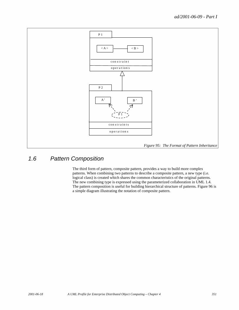
ad/2001-06-09 - Part I
2001-06-18 A UML Profile for Enterprise Distributed Object Computing – Chapter 4 351
o p e r a t i o n s
< A >
< B >
c o n s t r a in ts
o p e r a t i o n s
A’ B ’
c o n s t r a in t s
P 1
P 1
P 2
Figure 95: The Format of Pattern Inheritance
1.6 Pattern Composition
The third form of pattern, composite pattern, provides a way to build more complex patterns. When combining two patterns to describe a composite pattern, a new type (i.e. logical class) is created which shares the common characteristics of the original patterns. The new combining type is expressed using the parameterized collaboration in UML 1.4. The pattern composition is useful for building hierarchical structure of patterns. Figure 96 is a simple diagram illustrating the notation of composite pattern.
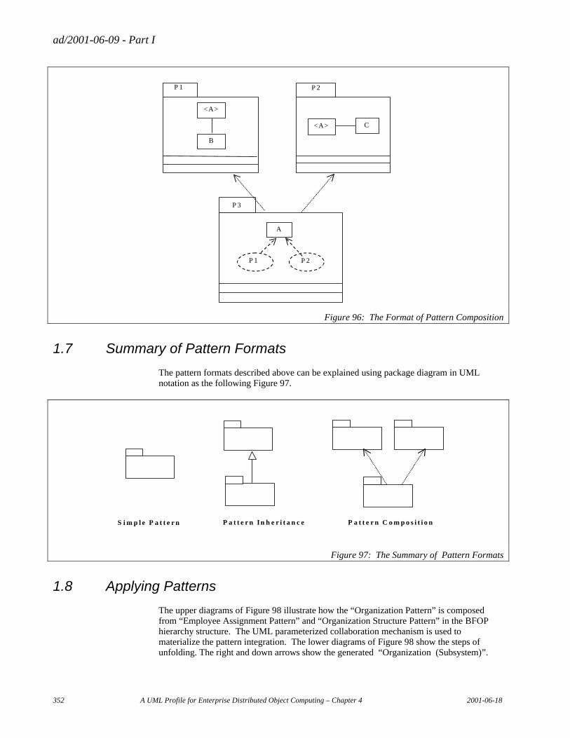
ad/2001-06-09 - Part I
352 A UML Profile for Enterprise Distributed Object Computing – Chapter 4 2001-06-18
A
P 1
P 2
P 3
<A>
P 2
<A>
P 1
B
C
Figure 96: The Format of Pattern Composition
1.7 Summary of Pattern Formats
The pattern formats described above can be explained using package diagram in UML notation as the following Figure 97.
Simple Pattern Pattern Inheritance Pattern C omposition
Figure 97: The Summary of Pattern Formats
1.8 Applying Patterns
The upper diagrams of Figure 98 illustrate how the “Organization Pattern” is composed from “Employee Assignment Pattern” and “Organization Structure Pattern” in the BFOP hierarchy structure. The UML parameterized collaboration mechanism is used to materialize the pattern integration. The lower diagrams of Figure 98 show the steps of unfolding. The right and down arrows show the generated “Organization (Subsystem)”.
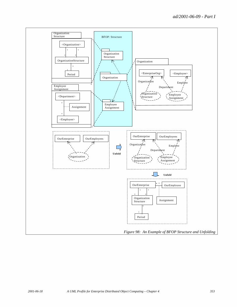
ad/2001-06-09 - Part I
2001-06-18 A UML Profile for Enterprise Distributed Object Computing – Chapter 4 353
Organization Structure
Organization
Employee Assignment
<Organization>
OrganizationStructure
Period <EnterpriseOrg>
<Department>
<Employee>
Assignment
OurEnterprise
Organization Structure
OurEmployee
Period
Assignment
Organization Structure
Employee Assignment
Organization
Organization Structure
Employee Assignment
Unfold
Department
Organization
1
1
*
*
* *
* *
*
1 1
1
* *
1
*
BFOP: Structure
<Employee>
Emplyee
OurEnterprise
Organization Structure
Employee Assignment
Department
Organization
OurEmployees
Emplyee
Organization
OurEnterprise OurEmployees
Unfold
Figure 98: An Example of BFOP Structure and Unfolding
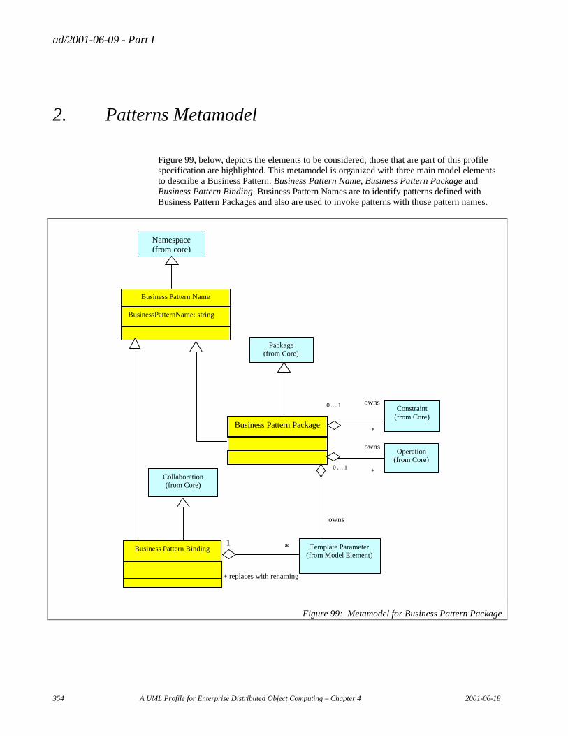
ad/2001-06-09 - Part I
354 A UML Profile for Enterprise Distributed Object Computing – Chapter 4 2001-06-18
2. Patterns Metamodel
Figure 99, below, depicts the elements to be considered; those that are part of this profile specification are highlighted. This metamodel is organized with three main model elements to describe a Business Pattern: Business Pattern Name, Business Pattern Package and Business Pattern Binding. Business Pattern Names are to identify patterns defined with Business Pattern Packages and also are used to invoke patterns with those pattern names.
Package (from Core)
Business Pattern Package
Constraint (from Core)
0 … 1
*
owns
Template Parameter (from Model Element)
owns
Operation (from Core)
0 … 1 *
owns
Collaboration (from Core)
Business Pattern Binding
1 *
+ replaces with renaming
Namespace (from core)
Business Pattern Name
BusinessPatternName: string
Figure 99: Metamodel for Business Pattern Package
ad/2001-06-09 - Part I
2001-06-18 A UML Profile for Enterprise Distributed Object Computing – Chapter 4 355
2.1 EDOC::Pattern Package
2.1.1 Business Pattern Name
Semantics
Business Pattern Name is the name of business patterns defined by Business Pattern Package.
UML base element(s) in the Profile
Class
Fully Scoped name
EDOC::Pattern::Business Pattern Name
Owned by
Package
Properties
Business Pattern Name
Business Pattern Name is the name of pattern defined in Business Pattern Package.
Related elements
Namespace
Business Pattern Name inherits from Namespace and adds the Business Pattern Name of Business Pattern Package.
Business Pattern Package
Business Pattern Package specializes Business Pattern Name for defining Business Pattern Package associating Business Pattern Name.
Business Pattern Binding
Business Pattern Binding specializes Business Pattern Name for invoking Business Pattern Package with associated Business Pattern Name.
Constraints
None
ad/2001-06-09 - Part I
356 A UML Profile for Enterprise Distributed Object Computing – Chapter 4 2001-06-18
2.1.2 Business Pattern Package
Semantics
Business Pattern Package is used to specify patterns and handle them as design elements.
UML base element(s) in the Profile
class
Fully Scoped name
EDOC::Pattern::Business Pattern Package
Owned by
Package
Properties
N/A
Related elements
Business Pattern Name
Business Pattern Package inherits from Business Pattern Name and adds elements for defining a pattern.
Package
Business Pattern Package inherits from package and adds elements for defining a pattern.
Template Parameter
Template Parameter represents formal parameters of defined pattern, which are class names to be replaced with actual class names at unfolding pattern.
Constraint
Constraint declares the semantics of defined pattern. A Business Pattern Package can be specified more precisely.
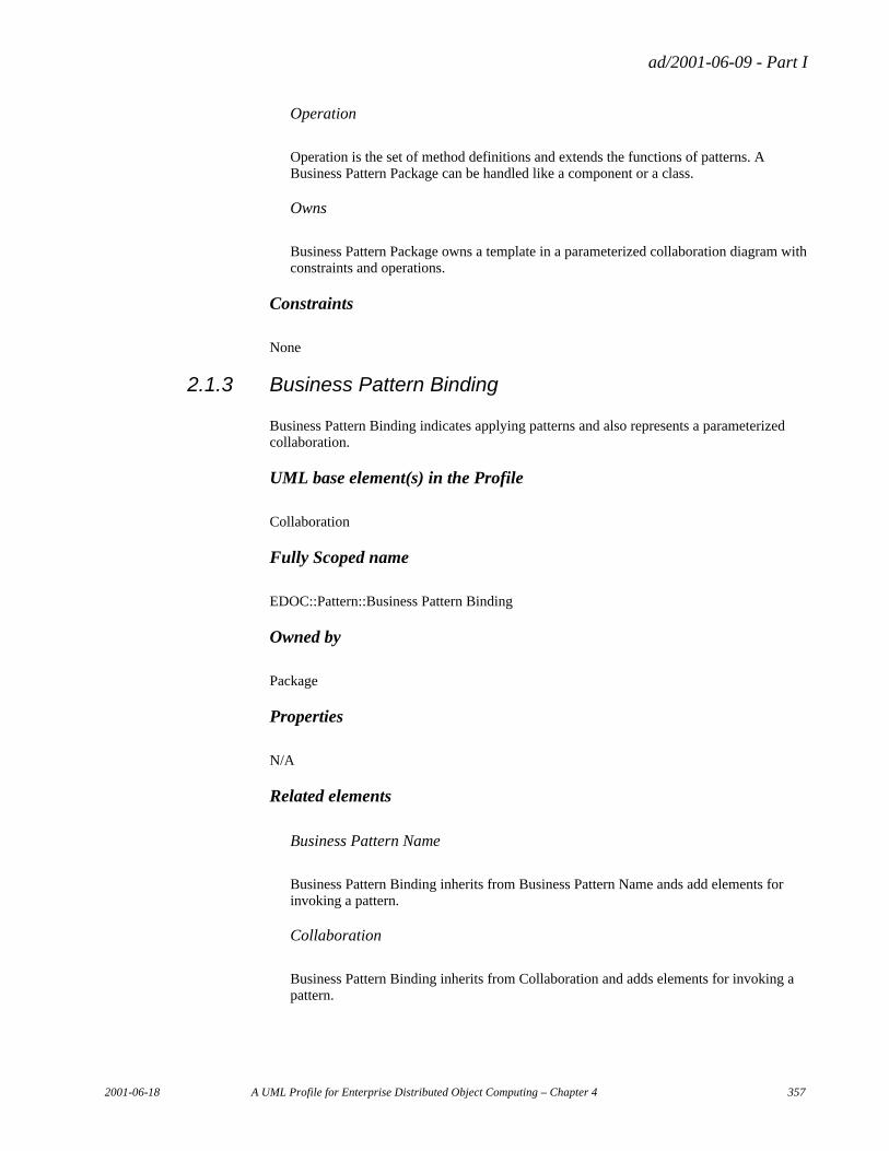
ad/2001-06-09 - Part I
2001-06-18 A UML Profile for Enterprise Distributed Object Computing – Chapter 4 357
Operation
Operation is the set of method definitions and extends the functions of patterns. A Business Pattern Package can be handled like a component or a class.
Owns
Business Pattern Package owns a template in a parameterized collaboration diagram with constraints and operations.
Constraints
None
2.1.3 Business Pattern Binding
Business Pattern Binding indicates applying patterns and also represents a parameterized collaboration.
UML base element(s) in the Profile
Collaboration
Fully Scoped name
EDOC::Pattern::Business Pattern Binding
Owned by
Package
Properties
N/A
Related elements
Business Pattern Name
Business Pattern Binding inherits from Business Pattern Name ands add elements for invoking a pattern.
Collaboration
Business Pattern Binding inherits from Collaboration and adds elements for invoking a pattern.

ad/2001-06-09 - Part I
358 A UML Profile for Enterprise Distributed Object Computing – Chapter 4 2001-06-18
Template Parameter
Template Parameter represents to replace the elements of patterns such as class names or attributes when patterns are unfolded in another pattern or class diagram.
Replaces with renaming
The element names such as class name, attribute name or method name used in patterns are replaced when patterns are unfolded.
Constraints
None
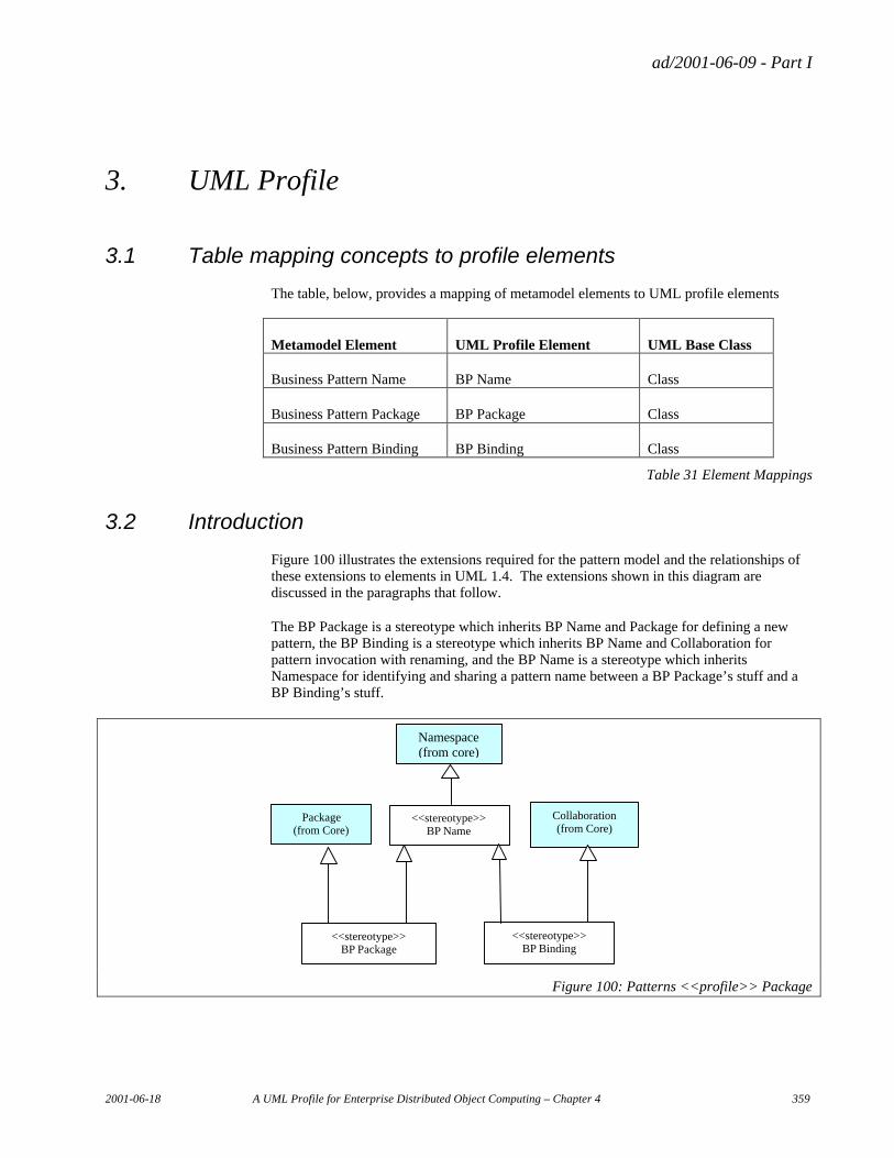
ad/2001-06-09 - Part I
2001-06-18 A UML Profile for Enterprise Distributed Object Computing – Chapter 4 359
3. UML Profile
3.1 Table mapping concepts to profile elements
The table, below, provides a mapping of metamodel elements to UML profile elements
Metamodel Element UML Profile Element UML Base Class
Business Pattern Name BP Name Class
Business Pattern Package BP Package Class
Business Pattern Binding BP Binding Class
Table 31 Element Mappings
3.2 Introduction
Figure 100 illustrates the extensions required for the pattern model and the relationships of these extensions to elements in UML 1.4. The extensions shown in this diagram are discussed in the paragraphs that follow.
The BP Package is a stereotype which inherits BP Name and Package for defining a new pattern, the BP Binding is a stereotype which inherits BP Name and Collaboration for pattern invocation with renaming, and the BP Name is a stereotype which inherits Namespace for identifying and sharing a pattern name between a BP Package’s stuff and a BP Binding’s stuff.
Package (from Core)
<<stereotype>> BP Package
Collaboration (from Core)
<<stereotype>> BP Binding
Namespace (from core)
<<stereotype>> BP Name
Figure 100: Patterns <<profile>> Package
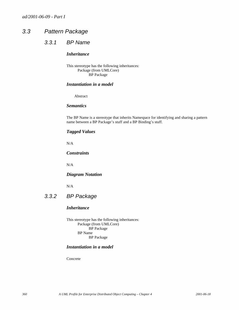
ad/2001-06-09 - Part I
360 A UML Profile for Enterprise Distributed Object Computing – Chapter 4 2001-06-18
3.3 Pattern Package
3.3.1 BP Name
Inheritance
This stereotype has the following inheritances: Package (from UMLCore) BP Package
Instantiation in a model
Abstract
Semantics
The BP Name is a stereotype that inherits Namespace for identifying and sharing a pattern name between a BP Package’s stuff and a BP Binding’s stuff.
Tagged Values
N/A
Constraints
N/A
Diagram Notation
N/A
3.3.2 BP Package
Inheritance
This stereotype has the following inheritances: Package (from UMLCore) BP Package BP Name BP Package
Instantiation in a model
Concrete
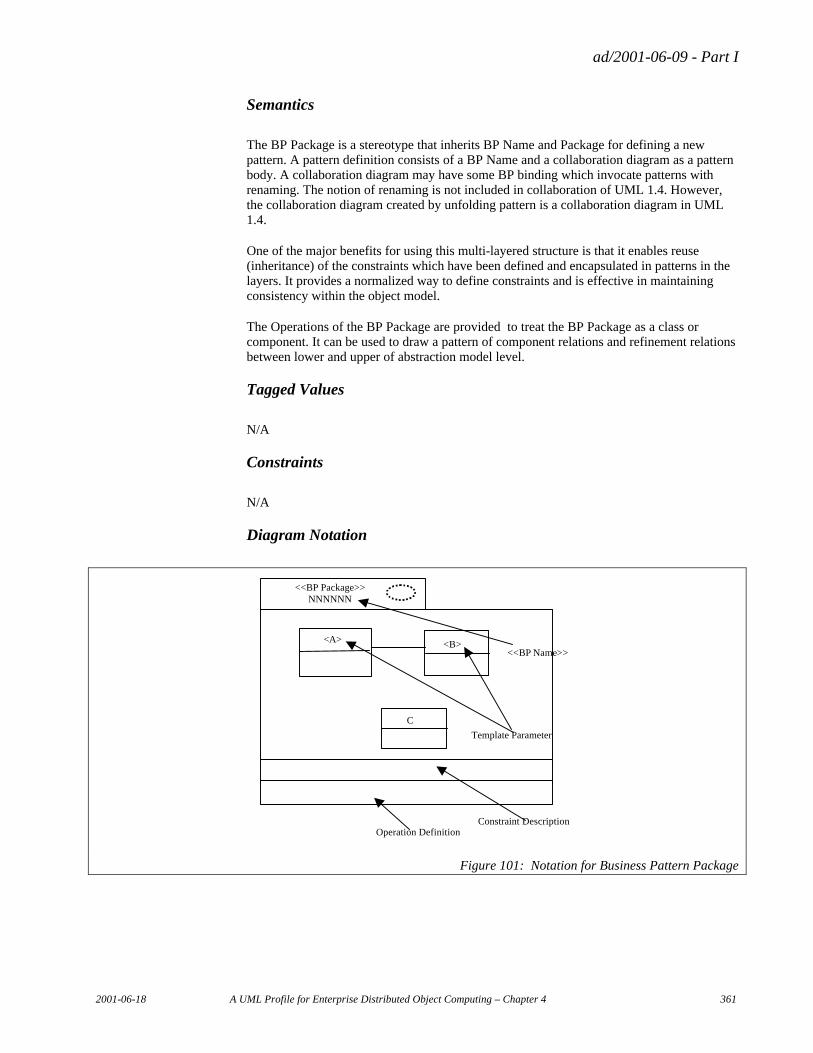
ad/2001-06-09 - Part I
2001-06-18 A UML Profile for Enterprise Distributed Object Computing – Chapter 4 361
Semantics
The BP Package is a stereotype that inherits BP Name and Package for defining a new pattern. A pattern definition consists of a BP Name and a collaboration diagram as a pattern body. A collaboration diagram may have some BP binding which invocate patterns with renaming. The notion of renaming is not included in collaboration of UML 1.4. However, the collaboration diagram created by unfolding pattern is a collaboration diagram in UML 1.4.
One of the major benefits for using this multi-layered structure is that it enables reuse (inheritance) of the constraints which have been defined and encapsulated in patterns in the layers. It provides a normalized way to define constraints and is effective in maintaining consistency within the object model.
The Operations of the BP Package are provided to treat the BP Package as a class or component. It can be used to draw a pattern of component relations and refinement relations between lower and upper of abstraction model level.
Tagged Values
N/A
Constraints
N/A
Diagram Notation
<<BP Package>>
NNNNNN
Template Parameter
<A> <B>
C
<<BP Name>>
Operation Definition Constraint Description
Figure 101: Notation for Business Pattern Package
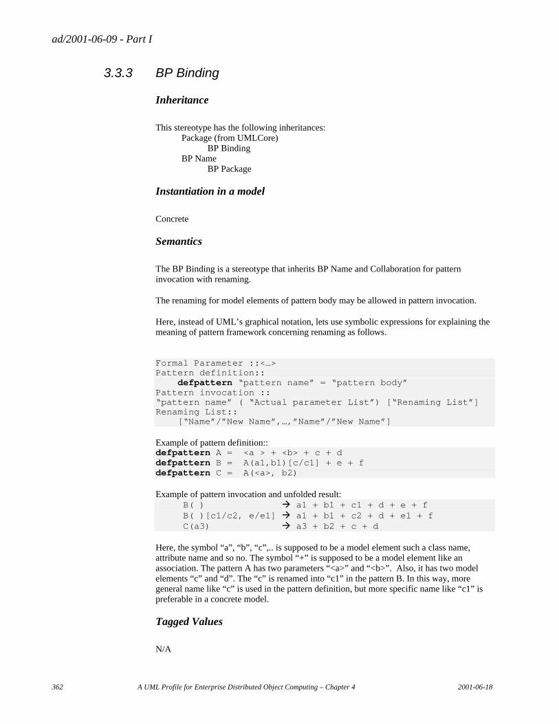
ad/2001-06-09 - Part I
362 A UML Profile for Enterprise Distributed Object Computing – Chapter 4 2001-06-18
3.3.3 BP Binding
Inheritance
This stereotype has the following inheritances: Package (from UMLCore) BP Binding BP Name BP Package
Instantiation in a model
Concrete
Semantics
The BP Binding is a stereotype that inherits BP Name and Collaboration for pattern invocation with renaming.
The renaming for model elements of pattern body may be allowed in pattern invocation.
Here, instead of UML’s graphical notation, lets use symbolic expressions for explaining the meaning of pattern framework concerning renaming as follows.
Formal Parameter ::<…> Pattern definition:: defpattern “pattern name” = “pattern body” Pattern invocation :: “pattern name” ( “Actual parameter List”) [“Renaming List”] Renaming List:: [“Name”/”New Name”,…,”Name”/”New Name”]
Example of pattern definition:: defpattern A = <a > + <b> + c + d defpattern B = A(a1,b1)[c/c1] + e + f defpattern C = A(<a>, b2)
Example of pattern invocation and unfolded result: B( ) à a1 + b1 + c1 + d + e + f B( )[c1/c2, e/e1] à a1 + b1 + c2 + d + e1 + f C(a3) à a3 + b2 + c + d
Here, the symbol “a”, “b”, “c”,.. is supposed to be a model element such a class name, attribute name and so no. The symbol “+” is supposed to be a model element like an association. The pattern A has two parameters “<a>” and “<b>”. Also, it has two model elements “c” and “d”. The “c” is renamed into “c1” in the pattern B. In this way, more general name like “c” is used in the pattern definition, but more specific name like “c1” is preferable in a concrete model.
Tagged Values
N/A
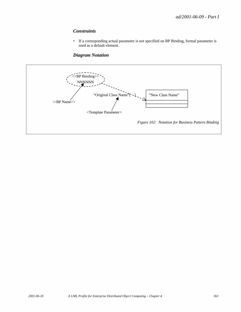
ad/2001-06-09 - Part I
2001-06-18 A UML Profile for Enterprise Distributed Object Computing – Chapter 4 363
Constraints
• If a corresponding actual parameter is not specified on BP Binding, formal parameter is used as a default element.
Diagram Notation
<Template Parameter>
<<BP Binding>>
NNNNNN
“New Class Name”
<<BP Name>>
“Original Class Name”[ ]
Figure 102: Notation for Business Pattern Binding

ad/2001-06-09 - Part I
2001-06-18 A UML Profile for Enterprise Distributed Object Computing – Chapter 5 365
Chapter 5 Technology Specific Models
Table of Contents
1. The EJB and Java Metamodels ..................................................................................................................... 367 1.1 Introduction .......................................................................................................................................... 367 1.2 The Java Metamodel............................................................................................................................. 367
1.2.1 Class Contents............................................................................................................................. 368 1.2.2 Polymorphism ............................................................................................................................. 374 1.2.3 JavaType ..................................................................................................................................... 374 1.2.4 TypeDescriptor ........................................................................................................................... 376 1.2.5 Data Types .................................................................................................................................. 377 1.2.6 Names ......................................................................................................................................... 377
1.3 The Enterprise JavaBeans Metamodel.................................................................................................. 378 1.3.1 Main............................................................................................................................................ 378 1.3.2 EJB.............................................................................................................................................. 383 1.3.3 Entity Bean.................................................................................................................................. 389 1.3.4 Assembly..................................................................................................................................... 390 1.3.5 EJB Implementation.................................................................................................................... 393 1.3.6 References to Resources ............................................................................................................. 395 1.3.7 Data Types .................................................................................................................................. 397
1.4 UML Profile ......................................................................................................................................... 398 1.4.1 Java Profile ................................................................................................................................. 398 1.4.2 EJB Profile.................................................................................................................................. 399
2. Flow Composition Model.............................................................................................................................. 400 2.1 Introduction .......................................................................................................................................... 400 2.2 FCMCore Package................................................................................................................................ 401
2.2.1 FCMComposition........................................................................................................................ 402 2.2.2 FCMComponent.......................................................................................................................... 402 2.2.3 FCMNode ................................................................................................................................... 403 2.2.4 FCMConnection.......................................................................................................................... 403 2.2.5 FCMOperation ............................................................................................................................ 403 2.2.6 FCMParameter ............................................................................................................................ 403 2.2.7 FCMCommand............................................................................................................................ 403 2.2.8 FCMFunction.............................................................................................................................. 403 2.2.9 FCMTerminal ............................................................................................................................. 404 2.2.10 FCMTerminalToNodeLink and FCMTerminalToTerminalLink ................................................ 404 2.2.11 FCMAnnotation .......................................................................................................................... 404 2.2.12 FCMSource and FCMSink.......................................................................................................... 404 2.2.13 FCMCompositionBinding........................................................................................................... 405 2.2.14 TDLangElement.......................................................................................................................... 405
2.3 FCM Package ....................................................................................................................................... 405 2.3.1 FCMControlLink ........................................................................................................................ 407 2.3.2 FCMDataLink ............................................................................................................................. 407

ad/2001-06-09 - Part I
366 A UML Profile for Enterprise Distributed Object Computing – Chapter 5 2001-06-18
2.3.3 FCMDecisionNode ..................................................................................................................... 407 2.3.4 FCMConditionalControlLink...................................................................................................... 408 2.3.5 FCMJoinNode............................................................................................................................. 408 2.3.6 FCMJoinCommand ..................................................................................................................... 408 2.3.7 FCMMappingNode ..................................................................................................................... 408 2.3.8 FCMMappingDataLink............................................................................................................... 408 2.3.9 FCMMapping.............................................................................................................................. 408
2.4 FCM Profile.......................................................................................................................................... 409 2.5 Example................................................................................................................................................ 410
ad/2001-06-09 - Part I
2001-06-18 A UML Profile for Enterprise Distributed Object Computing – Chapter 5 367
1. The EJB and Java Metamodels
1.1 Introduction
This section describes the Enterprise JavaBeans ™ metamodel abstracted for the purpose of design and deployment of application components to the Enterprise JavaBeans architecture. This metamodel describes the EJB 1.1 specification, specifically the content of the “Public Release” version of the 1.1 specification. The metamodel is included to demonstrate the generality of the proposed analysis profile by showing that it can be mapped to more than one implementation architecture. The submitters believe this generality should be provided to maximize the utility of the profile.
The metamodel is intended to define sufficient structure to support the EJB development life cycle, i.e., the creation, assembly and deployment of Enterprise JavaBeans. As the Java language is the foundation to the Enterprise JavaBeans architecture, a Java metamodel has been developed as a foundation to the Enterprise JavaBeans metamodel. The intent of the Java metamodel is to capture sufficient detail to support the Enterprise JavaBeans metamodel. It is not a complete metamodel of the Java language. The Java metamodel describes the Java language specification used by EJB 1.1, i.e., Java language specification version 1.3.
The following pages will describe the two metamodels. Each metamodel is presented as a series of class diagrams. Each class diagram is followed by a description of the important features of the diagram. Each metamodel element can also be mapped to a profile representation using the patterns described in the UML Profile for MOF that is included in this document. As the metamodel is completed with the constraints spelled out in the Enterprise JavaBeans architecture, those can also be projected into the profile. The submitters intend the metamodel to be used as input for the UML Profile for EJB now in public draft within the Java Community Process under JSR-000026 (see http://jcp.org/jsr/detail/26.jsp) through such a mapping.
1.2 The Java Metamodel
The Java metamodel is described using the following 5 diagrams:
Figure 103, Class Contents describes Java Classes/Interfaces/Exceptions;
Figure 104, Polymorphism describes Java polymorphism;
Figure 105, JavaType describes how Java typed elements are related to their types;
Figure 107, Data Types describes the basic Java data types;
Figure 108, Names factors the name attribute into a superclass
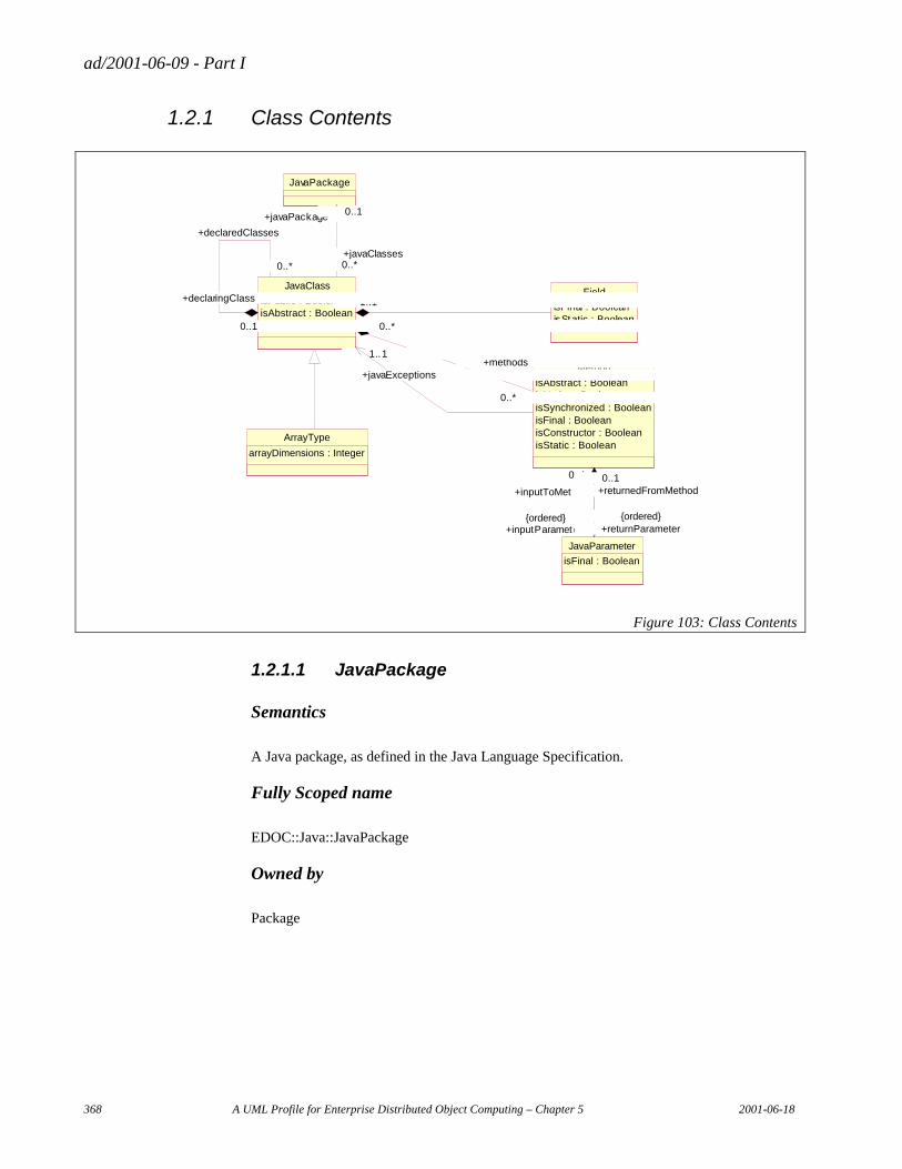
ad/2001-06-09 - Part I
368 A UML Profile for Enterprise Distributed Object Computing – Chapter 5 2001-06-18
1.2.1 Class Contents
ArrayType
arrayDimensions : Integer
Field
isFinal : BooleanisStatic : Boolean
JavaPackage
JavaClass
isPublic : BooleanisAbstract : BooleanisFinal : Boolean
0..*1..1
+fields
0..*1..1
0..*
0..1
+declaredClasses
0..*
+declaringClass
0..1
0..*
0..1
+javaClasses0..*
+javaPackage 0..1
Method
isAbstract : BooleanisNative : BooleanisSynchronized : BooleanisFinal : BooleanisConstructor : BooleanisStatic : Boolean
0..*
1..1+methods
0..*
1..1
0..*
+javaExceptions
0..*
JavaParameter
isFinal : Boolean
0..1
0..*
+inputToMethod
0..1
+inputParameters0..*{ordered}
0..1
0..1
+returnedFromMethod0..1
+returnParameter0..1 {ordered}
Figure 103: Class Contents
1.2.1.1 JavaPackage
Semantics
A Java package, as defined in the Java Language Specification.
Fully Scoped name
EDOC::Java::JavaPackage
Owned by
Package
ad/2001-06-09 - Part I
2001-06-18 A UML Profile for Enterprise Distributed Object Computing – Chapter 5 369
Properties
Related elements
JavaClass
The Java classes contained in the package.
Constraints
N/A
1.2.1.2 JavaClass
Semantics
A Java class, as defined in the Java Language Specification.
Fully Scoped name
EDOC::Java::JavaClass
Owned by
JavaPackage
Properties
isPublic
Boolean value indicating whether the class is public.
isAbstract
Boolean value indicating whether the class is abstract.
IsFinal
Boolean value indicating whether the class is final.
Related elements
JavaPackage
The Java package the class is in.
ad/2001-06-09 - Part I
370 A UML Profile for Enterprise Distributed Object Computing – Chapter 5 2001-06-18
JavaClass
Declared/Declaring classes.
Field
The fields in the class.
Method
• The methods on the class.
• The methods that throw this exception.
JavaParameter
The parameter type.
ArrayType
• Subclasses JavaClass, adding array dimensions.
• The type of the components in the array.
Constraints
N/A
1.2.1.3 Field
Semantics
A Java field, as defined in the Java Language Specification.
Fully Scoped name
EDOC::Java::Field
Owned by
JavaClass
Properties.
isFinal
Boolean value indicating whether the field is final.
ad/2001-06-09 - Part I
2001-06-18 A UML Profile for Enterprise Distributed Object Computing – Chapter 5 371
IsStatic
Boolean value indicating whether the field is static.
Related elements
JavaClass
The class containing the field.
Constraints
N/A
1.2.1.4 Method
Semantics
A Java method, as defined in the Java Language Specification.
Fully Scoped name
EDOC::Java::Method
Owned by
JavaClass
Properties.
isAbstract
Boolean value indicating whether the method is abstract.
isNative
Boolean value indicating whether the method is native.
isSynchronized
Boolean value indicating whether the method is synchronized.
isFinal
Boolean value indicating whether the method is final.
ad/2001-06-09 - Part I
372 A UML Profile for Enterprise Distributed Object Computing – Chapter 5 2001-06-18
IsConstructor
Boolean value indicating whether the method s a constructor.
IsStatic
Boolean value indicating whether the method is static.
Related Elements
JavaClass
• The class the method belongs to.
• The exceptions the method throws.
JavaParameter
The input and return parameters on the method.
1.2.1.5 JavaParameter
Semantics
A Java parameter, as defined in the Java Language Specification.
Fully Scoped name
EDOC::Java::Parameter
Owned by
Method
Properties.
isFinal
Boolean value indicating whether the parameter is final.
Related elements
Method
The method the parameter is an input or return parameter for.
ad/2001-06-09 - Part I
2001-06-18 A UML Profile for Enterprise Distributed Object Computing – Chapter 5 373
Constraints
N/A
1.2.1.6 ArrayType
Semantics
A Java array type, as defined in the Java Language Specification.
Fully Scoped name
EDOC::Java:ArrayType
Owned by
Package
Properties.
arrayDimensions
Integer value giving the dimensions of the array type.
Related elements
JavaClass
• Subclasses JavaClass and adds array dimensions.
• ArrayType uses JavaClass to identify the type of its components.
Constraints
N/A
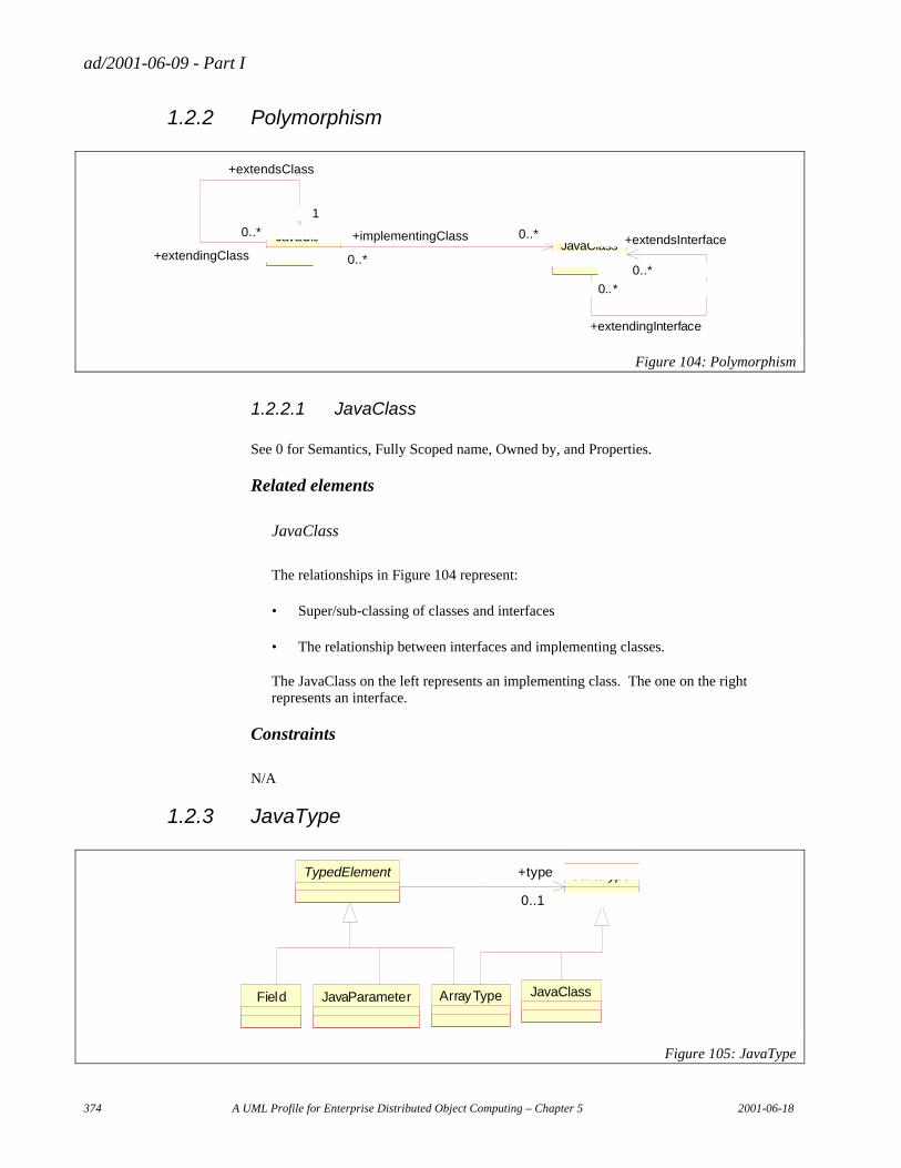
ad/2001-06-09 - Part I
374 A UML Profile for Enterprise Distributed Object Computing – Chapter 5 2001-06-18
1.2.2 Polymorphism
JavaClass
1
0..*
+extendsClass
1
+extendingClass
0..*JavaClass
0..*
0..*
+implementingClass 0..*
+implementsInterface0..*
0..*
0..*
+extendingInterface
0..*
+extendsInterface
0..*
Figure 104: Polymorphism
1.2.2.1 JavaClass
See 0 for Semantics, Fully Scoped name, Owned by, and Properties.
Related elements
JavaClass
The relationships in Figure 104 represent:
• Super/sub-classing of classes and interfaces
• The relationship between interfaces and implementing classes.
The JavaClass on the left represents an implementing class. The one on the right represents an interface.
Constraints
N/A
1.2.3 JavaType
Field JavaParameter ArrayType JavaClass
JavaTypeTypedElement
0..1
+type
0..1
Figure 105: JavaType
ad/2001-06-09 - Part I
2001-06-18 A UML Profile for Enterprise Distributed Object Computing – Chapter 5 375
Field, JavaParameter, ArrayType, and JavaClass are described in 1.2.1. TypedElement
Semantics
Abstract class that identifies subclasses as having a type as part of their definition.
Fully Scoped name
EDOC::Java::TypedElement
Owned by
Package
Properties
Related elements
JavaType
The associated type.
Field, JavaParameter, ArrayType
Concrete subclasses.
Constraints
N/A
1.2.3.1 JavaType
Semantics
Abstract class whose subclasses are the Java types.
Fully Scoped name
EDOC::Java::JavaType
Owned by
Package
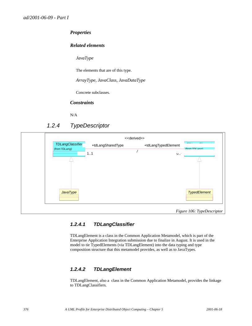
ad/2001-06-09 - Part I
376 A UML Profile for Enterprise Distributed Object Computing – Chapter 5 2001-06-18
Properties
Related elements
JavaType
The elements that are of this type.
ArrayType, JavaClass, JavaDataType
Concrete subclasses.
Constraints
N/A
1.2.4 TypeDescriptor
TDLangClassifier(from TDLang)
TDLangElement(from TDLang)
1..1 0..*
+tdLangSharedType
1..1
+tdLangTypedElement
0..*/
<<derived>>
TypedElementJavaType
Figure 106: TypeDescriptor
1.2.4.1 TDLangClassifier
TDLangElement is a class in the Common Application Metamodel, which is part of the Enterprise Application Integration submission due to finalize in August. It is used in the model to tie TypedElements (via TDLangElement) into the data typing and type composition structure that this metamodel provides, as well as to JavaTypes.
1.2.4.2 TDLangElement
TDLangElement, also a class in the Common Application Metamodel, provides the linkage to TDLangClassifiers.
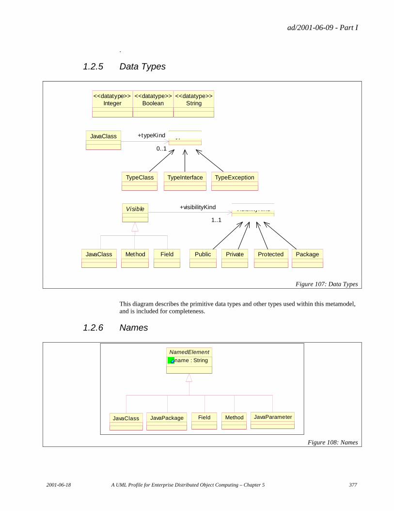
ad/2001-06-09 - Part I
2001-06-18 A UML Profile for Enterprise Distributed Object Computing – Chapter 5 377
.
1.2.5 Data Types
JavaClass Method Field
VisibilityKindVisible
1..1
+visibilityKind
1..1
Public Private Protected Package
TypeKindJavaClass
0..1
+typeKind
0..1
TypeClass TypeInterface TypeException
Integer<<datatype>>
Boolean<<datatype>>
String<<datatype>>
Figure 107: Data Types
This diagram describes the primitive data types and other types used within this metamodel, and is included for completeness.
1.2.6 Names
NamedElement
name : String
JavaClass JavaPackage Field Method JavaParameter
Figure 108: Names
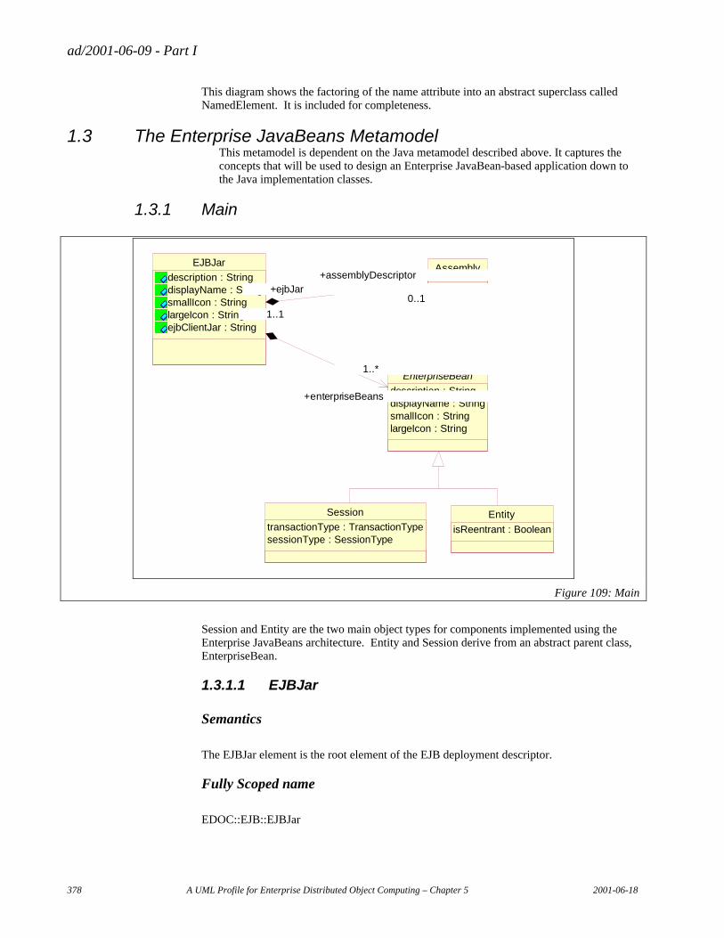
ad/2001-06-09 - Part I
378 A UML Profile for Enterprise Distributed Object Computing – Chapter 5 2001-06-18
This diagram shows the factoring of the name attribute into an abstract superclass called NamedElement. It is included for completeness.
1.3 The Enterprise JavaBeans Metamodel This metamodel is dependent on the Java metamodel described above. It captures the concepts that will be used to design an Enterprise JavaBean-based application down to the Java implementation classes.
1.3.1 Main
EJBJar
description : StringdisplayName : StringsmallIcon : StringlargeIcon : StringejbClientJar : String
Session
transactionType : TransactionTypesessionType : SessionType
Entity
isReentrant : Boolean
Assembly
EnterpriseBean
description : StringdisplayName : StringsmallIcon : StringlargeIcon : String
0..1
1..1
+assemblyDescriptor
0..1+ejbJar
1..1
1..*
+enterpriseBeans
1..*
Figure 109: Main
Session and Entity are the two main object types for components implemented using the Enterprise JavaBeans architecture. Entity and Session derive from an abstract parent class, EnterpriseBean.
1.3.1.1 EJBJar
Semantics
The EJBJar element is the root element of the EJB deployment descriptor.
Fully Scoped name
EDOC::EJB::EJBJar
ad/2001-06-09 - Part I
2001-06-18 A UML Profile for Enterprise Distributed Object Computing – Chapter 5 379
Owned by
Package
Properties
description
The description element is used by the ejb-jar file producer to provide text describing the parent element. The description element should include any information that the ejb-jar file producer wants to provide to the consumer of the ejb-jar file (i.e. to the Deployer). Typically, the tools used by the ejb-jar file consumer will display the description when processing the parent element.
displayName
The display-name element contains a short name that is intended to be display by tools. Example: <display-name>Employee Self Service</display-name>.
SmallIcon
Optional small icon file name.
LargeIcon
Optional small icon file name.
EjbClientJar
Optional name of an ejb-client-jar file for the ejb-jar.
Related elements
Assembly
Assembly descriptor.
EnterpriseBean
Included EnterpriseBeans.
Constraints
N/A
ad/2001-06-09 - Part I
380 A UML Profile for Enterprise Distributed Object Computing – Chapter 5 2001-06-18
1.3.1.2 Assembly
Semantics
The assembly-descriptor element contains application-assembly information. The application-assembly information consists of the following parts: the definition of security roles, the definition of method permissions, and the definition of transaction attributes for enterprise beans with container-managed transaction demarcation. All the parts are optional in the sense that they are omitted if the lists represented by them are empty. Providing an assembly-descriptor in the deployment descriptor is optional for the ejb-jar file producer.
Fully Scoped name
EDOC::EJB::Assembly
Owned by
EJBJar
Properties
Related elements
EJBJar
Identifies the deployment descriptor it belongs to.
Constraints
N/A
1.3.1.3 EnterpriseBean
Semantics
EnterpriseBean is a class. It can have attributes, operations, and associations. These are actually derived/filtered from its implementation classes and interfaces. For mapping and browsing purposes, though, you would like the EnterpriseBean to appear as a class.
In this light, even Session Beans can have associations and properties implemented by their bean. For example, it would be meaningful to describe associations from a Session to the Entities that it uses to perform its work.
Fully Scoped name
EDOC::EJB::EnterpriseBean
ad/2001-06-09 - Part I
2001-06-18 A UML Profile for Enterprise Distributed Object Computing – Chapter 5 381
Owned by
EJBJar
Properties
Description
The description element is used by the ejb-jar file producer to provide text describing the parent element. The description element should include any information that the ejb-jar file producer wants to provide to the consumer of the ejb-jar file (i.e. to the Deployer). Typically, the tools used by the ejb-jar file consumer will display the description when processing the parent element.
displayName
The display-name element contains a short name that is intended to be display by tools.
SmallIcon
Optional small icon file name.
LargeIcon
Optional small icon file name.
Related elements
EJBJar
Identifies the deployment descriptor it belongs to.
Session, Entity
The concrete subclasses of EnterpriseBean
Constraints
N/A
ad/2001-06-09 - Part I
382 A UML Profile for Enterprise Distributed Object Computing – Chapter 5 2001-06-18
1.3.1.4 Session
Semantics
A transient object which provides more behavior than state. It maps to session bean in the Enterprise JavaBean specification.
Fully Scoped name
EDOC::EJB::Session
Owned by
Package
Properties
transactionType
The transaction-type element specifies an enterprise bean's transaction management type.
sessionType
Whether the session bean is stateful or stateless.
Related elements
EnterpriseBean
Abstract superclass.
Constraints
N/A
1.3.1.5 Entity
Semantics
A persistent object which that is more state-oriented than behavior-oriented. It maps to entity bean in the Enterprise JavaBean specification.
Fully Scoped name
EDOC::EJB::Entity
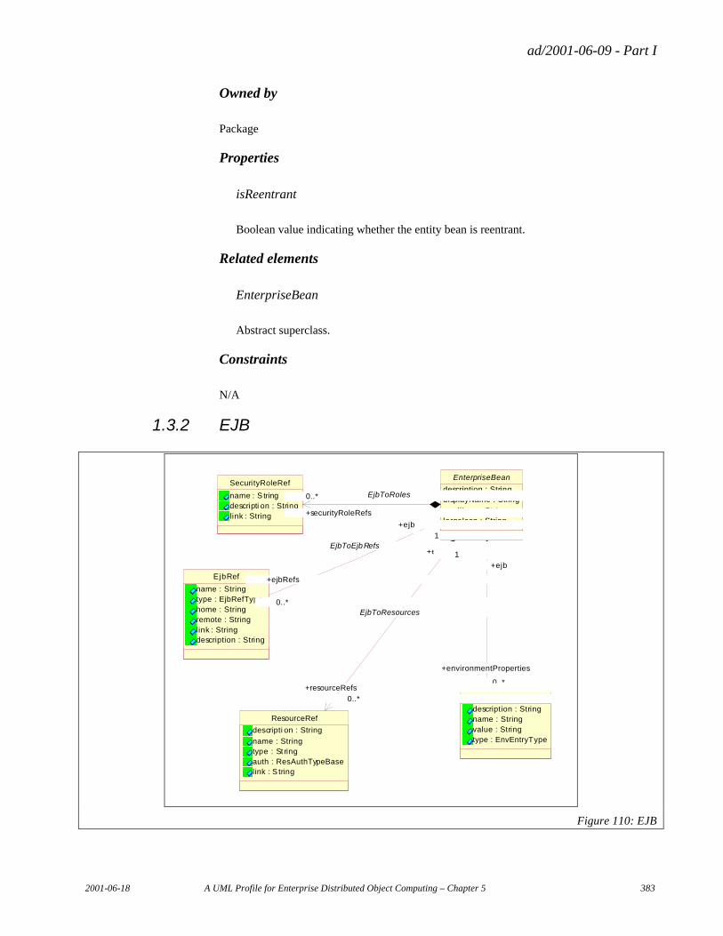
ad/2001-06-09 - Part I
2001-06-18 A UML Profile for Enterprise Distributed Object Computing – Chapter 5 383
Owned by
Package
Properties
isReentrant
Boolean value indicating whether the entity bean is reentrant.
Related elements
EnterpriseBean
Abstract superclass.
Constraints
N/A
1.3.2 EJB
EnvEntry
description : Stringname : Stringvalue : Stringtype : EnvEntryType
ResourceRef
descripti on : String
name : Stringtype : St ringauth : ResAuthTypeBaselink : S tring
SecurityRoleRef
name : S tringdescripti on : Stringlink : String
EjbRef
name : Stringtype : EjbRefTypehome : Stringremote : Stringlink : Stringdescription : String
EnterpriseBean
description : StringdisplayName : String
smallIcon : StringlargeIcon : String
0..*
1
+environmentProperties
0..*
+ejb
1
EjbToEnvironmentProperties
0..*
1
+resourceRefs
0..*
+ejb 1
EjbToResources
0..* 1
+securityRoleRefs
0..* 1EjbToRoles
0..*
1
+ejbRefs
0..*
+ejb
1EjbToEjbRefs
Figure 110: EJB
ad/2001-06-09 - Part I
384 A UML Profile for Enterprise Distributed Object Computing – Chapter 5 2001-06-18
This diagram shows how EnterpriseBean is associated with objects that enable binding the deployed Enterprise Bean into the runtime environment and managing access to the bean.
1.3.2.1 EnterpriseBean
Semantics, Fully Scoped name, Owned by, and Properties are described in 1.3.1.3.
Related elements
SecurityRoleRef
Security role references by the enterprise bean.
EJBRef
References to the homes of other enterprise beans using “logical” names.
ResourceRef
References to external resources.
EnvEntry
Environment entries access by the enterprise bean.
Constraint
N/A
1.3.2.2 SecurityRoleRef
Semantics
Security role references by an enterprise bean
Fully Scoped name
EDOC::EJB::SecurityRoleRef
Owned by
EnterpriseBean
ad/2001-06-09 - Part I
2001-06-18 A UML Profile for Enterprise Distributed Object Computing – Chapter 5 385
Properties
name
Name of the security role reference.
Description
Optional description text.
link
Used to link a security role reference to a defined security role. link must contain the name of a defined security role.
Related elements
EnterpriseBean
Enterprise bean that contains the reference.
Constraints
N/A
1.3.2.3 EJBRef
Semantics
The declaration of a reference to an enterprise bean’s home.
Fully Scoped name
EDOC::EJB::EJBRef
Owned by
EnterpriseBean
Properties
name
Name of the reference.
ad/2001-06-09 - Part I
386 A UML Profile for Enterprise Distributed Object Computing – Chapter 5 2001-06-18
type
The expected type of the referenced enterprise bean.
home
The fully-qualified name of the enterprise bean’s home interface.
remote
The fully-qualified name of the enterprise bean’s remote interface.
link
Links an EJB reference to a target enterprise bean.
Description
Optional description text.
Related elements
EnterpriseBean
Enterprise bean that contains the reference.
Constraints
N/A
1.3.2.4 ResourceRef
Semantics
Declaration of an enterprise bean’s reference to an external resource.
Fully Scoped name
EDOC::EJB::ResourceRef
Owned by
EnterpriseBean
ad/2001-06-09 - Part I
2001-06-18 A UML Profile for Enterprise Distributed Object Computing – Chapter 5 387
Properties
Description
Optional description text.
Name
Name of the environment entry used in the enterprise bean.
type
Type of the resource manager connection factory that the enterprise bean expects.
auth
Specifies whether the enterprise bean signs on programmatically to the resource manager, or whether the Container will sign on to the resource manager on behalf of the bean.
link
Link to a resource manager connection factory that exists in the operational environment.
Related elements
EnterpriseBean
Enterprise bean that contains the reference.
Constraints
1.3.2.5 EnvEntry
Semantics
Declaration of an environment entry for an enterprise bean.
Fully Scoped name
EDOC::EJB::EnvEntry
Owned by
EnterpriseBean
ad/2001-06-09 - Part I
388 A UML Profile for Enterprise Distributed Object Computing – Chapter 5 2001-06-18
Properties
name
Name of the environment entry.
Description
Optional description text.
value
Value of the environment entry.
Type
Expected type of the environment entry’s value
Related elements
EnterpriseBean
Enterprise bean that contains the reference.
Constraints
N/A
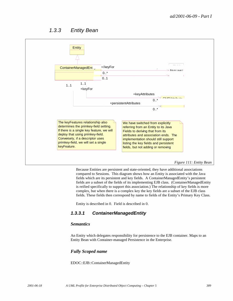
ad/2001-06-09 - Part I
2001-06-18 A UML Profile for Enterprise Distributed Object Computing – Chapter 5 389
1.3.3 Entity Bean
The keyFeatures relationship also determines the primkey-field setting. If there is a single key feature, we will deploy that using primkey-field. Conversely, if a descriptor uses primkey-field, we will set a single keyFeature.
We have switched from explicitly referring from an Entity to its Java Fields to deriving that from its attributes and association ends. The implementation should still support listing the key fields and persistent fields, but not adding or removing
Field(f ro m j ava )
CMPAttribute
ContainerManagedEntity
1..*0..*
+/keyFields
1..*
+/keyFor
0..*
0..*0..1 +/persistentFields 0..*0..1
CmpToPers istentFields
0..*
1..1
+persistentAttributes
0..*
1..1
0..*
1..1
+keyAttributes
0..*
+keyFor
1..1
Entity
Figure 111: Entity Bean
Because Entities are persistent and state-oriented, they have additional associations compared to Sessions. This diagram shows how an Entity is associated with the Java fields which are its persistent and key fields. A ContainerManagedEntity’s persistent fields are a subset of the fields of its implementing EJB class. (ContainerManagedEntity is reified specifically to support this association.) The relationship of key fields is more complex, but when there is a complex key the key fields are a subset of the EJB class fields. These fields then correspond by name to fields of the Entity’s Primary Key Class. Entity is described in 0. Field is described in 0.
1.3.3.1 ContainerManagedEntity
Semantics
An Entity which delegates responsibility for persistence to the EJB container. Maps to an Entity Bean with Container-managed Persistence in the Enterprise.
Fully Scoped name
EDOC::EJB::ContainerManagedEntity
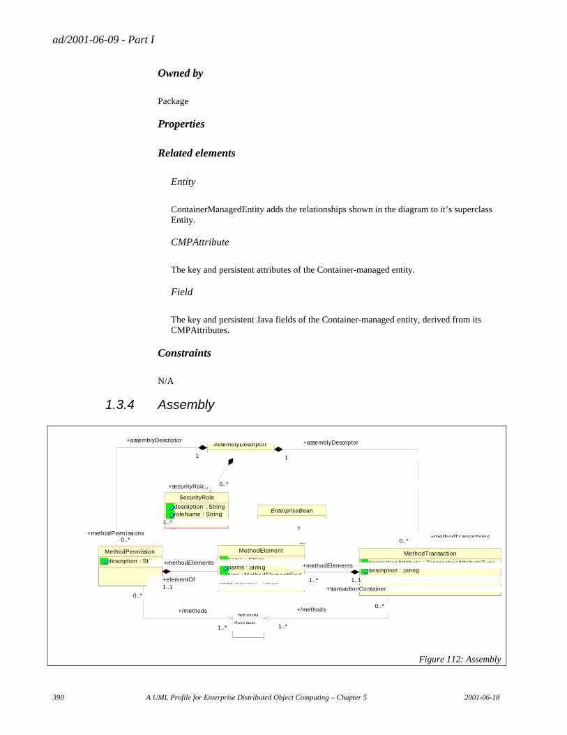
ad/2001-06-09 - Part I
390 A UML Profile for Enterprise Distributed Object Computing – Chapter 5 2001-06-18
Owned by
Package
Properties
Related elements
Entity
ContainerManagedEntity adds the relationships shown in the diagram to it’s superclass Entity.
CMPAttribute
The key and persistent attributes of the Container-managed entity.
Field
The key and persistent Java fields of the Container-managed entity, derived from its CMPAttributes.
Constraints
N/A
1.3.4 Assembly
EnterpriseBean
Method
(from java)
MethodElement
name : Stri ngparms : Strin gtype : M etho dElementKinddescrip tion : String
1
0..*
1
0..*
MethodPermission
description : String
1..*
0..*
+/methods
1..*
0..*
1..*
1..1
+methodElements
1..*+elementOf1..1
MethodTransaction
transactionAttribute : TransactionAttributeTypedescription : String
1..*
0..*+/methods
1..*
0..*
1..* 1..1
+methodElements
1..*
+transactionContainer
1..1
SecurityRole
description : StringroleName : String
1..*
+roles
1..*
AssemblyDescripto r
1
0..*
+assemblyDescriptor
1
+methodPerm issi ons0..*
1
0..*
+assemblyDescriptor
1
+methodTransact ions0..*
0..*+securityRoles 0..*
Figure 112: Assembly
ad/2001-06-09 - Part I
2001-06-18 A UML Profile for Enterprise Distributed Object Computing – Chapter 5 391
When the components of an Enterprise JavaBean application are ready to be used, the assembly step adds permission and transaction structure to the components based on their usage in the application. Roles are authorized to methods based on the application’s needs. (AllMethodPermission captures the case where a role is authorized to all the methods of a class without having to enumerate those methods.) Based on the flow of control and the units of work defined in an application, the transaction requirements of methods can be declared. The method permissions and method transaction declarations are bundled into an Assembly Descriptor that is then realized in the deployed application artifacts.
1.3.4.1 AssemblyDescriptor
Semantics, Properties, Related elements map to the assembly-descriptor element in the Enterprise JavaBean specification.
Fully Scoped name
EDOC::EJB:AssemblyDescriptor
Owned by
Package
1.3.4.2 SecurityRole
Semantics, Properties, Related elements map to the security-role element in the Enterprise JavaBean specification.
Fully Scoped name
EDOC::EJB:SecurityRole
Owned by
AssemblyDescriptor
1.3.4.3 MethodElement
Semantics, Properties, Related elements map to the method element in the Enterprise JavaBean specification.
Fully Scoped name
EDOC::EJB::MethodPermission
Owned by
MethodTransaction
ad/2001-06-09 - Part I
392 A UML Profile for Enterprise Distributed Object Computing – Chapter 5 2001-06-18
1.3.4.4 MethodPermission
Semantics, Properties, Related elements map to the method-permission element in the Enterprise JavaBean specification.
Fully Scoped name
EDOC::EJB::MethodPermission
Owned by
MethodElement
1.3.4.5 MethodTransaction
Semantics, Properties, Related elements map to the container-transaction element in the Enterprise JavaBean specification.
Fully Scoped name
EDOC::EJB::MethodTransaction
Owned by
AssemblyDescriptor
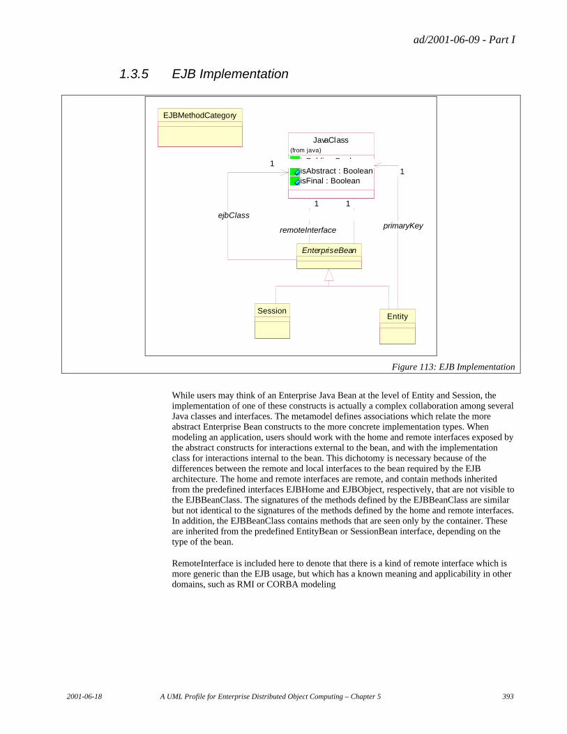
ad/2001-06-09 - Part I
2001-06-18 A UML Profile for Enterprise Distributed Object Computing – Chapter 5 393
1.3.5 EJB Implementation
EJBMethodCategory
Session
EnterpriseBean
JavaClass
isPublic : BooleanisAbstract : BooleanisFinal : Boolean
(from java)
11
remoteInterface
11
homeInterface
11
ejbClass
Entity
11
primaryKey
Figure 113: EJB Implementation
While users may think of an Enterprise Java Bean at the level of Entity and Session, the implementation of one of these constructs is actually a complex collaboration among several Java classes and interfaces. The metamodel defines associations which relate the more abstract Enterprise Bean constructs to the more concrete implementation types. When modeling an application, users should work with the home and remote interfaces exposed by the abstract constructs for interactions external to the bean, and with the implementation class for interactions internal to the bean. This dichotomy is necessary because of the differences between the remote and local interfaces to the bean required by the EJB architecture. The home and remote interfaces are remote, and contain methods inherited from the predefined interfaces EJBHome and EJBObject, respectively, that are not visible to the EJBBeanClass. The signatures of the methods defined by the EJBBeanClass are similar but not identical to the signatures of the methods defined by the home and remote interfaces. In addition, the EJBBeanClass contains methods that are seen only by the container. These are inherited from the predefined EntityBean or SessionBean interface, depending on the type of the bean.
RemoteInterface is included here to denote that there is a kind of remote interface which is more generic than the EJB usage, but which has a known meaning and applicability in other domains, such as RMI or CORBA modeling
ad/2001-06-09 - Part I
394 A UML Profile for Enterprise Distributed Object Computing – Chapter 5 2001-06-18
1.3.5.1 EJBMethodCategory
Semantics
EJBMethodCategoryJava defines a mechanism which allows the modeler to group EJB-specific method types such as create methods, finder methods, remote methods, and home methods.
Fully Scoped name
EDOC::EJB::EJBMethodCategory
Owned by
Package
Properties
Related elements
Constraints
1.3.5.2 EnterpriseBean
EnterpriseBean is described in 1.3.1.3.
Related elements
JavaClass
• The EjbClass relationship maps to the ejb-class element of the Enterprise JavaBean specification.
• The remoteInterface relationship points to a Java interface that represents the remotely visible interface to an Enterprise Bean. Maps to the remote element in the Enterprise JavaBean specification.
• The homeInterface relationship points to a Java interface which includes the factory and finder behavior of an Enterprise Bean. Maps to the home element in the Enterprise JavaBean specification.
1.3.5.3 Entity
Entity is described in 0.
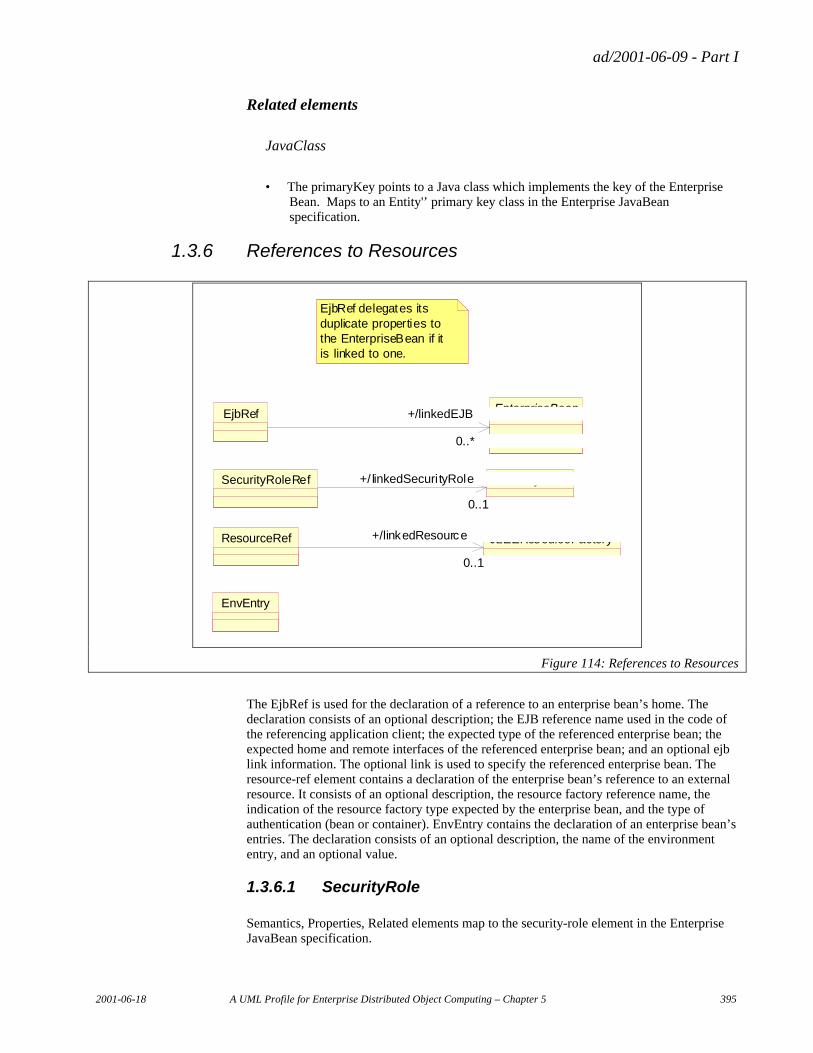
ad/2001-06-09 - Part I
2001-06-18 A UML Profile for Enterprise Distributed Object Computing – Chapter 5 395
Related elements
JavaClass
• The primaryKey points to a Java class which implements the key of the Enterprise Bean. Maps to an Entity'’ primary key class in the Enterprise JavaBean specification.
1.3.6 References to Resources
EnvEntry
EjbRef delegates its duplicate properties to the EnterpriseBean if it is linked to one.
EnterpriseBeanEjbRef
0..*
+/linkedEJB
0..*
SecurityRoleSecurityRoleRef
0..1
+/ linkedSecurityRole
0..1
J2EEResourceFactoryResourceRef
0..1
+/linkedResource
0..1
Figure 114: References to Resources
The EjbRef is used for the declaration of a reference to an enterprise bean’s home. The declaration consists of an optional description; the EJB reference name used in the code of the referencing application client; the expected type of the referenced enterprise bean; the expected home and remote interfaces of the referenced enterprise bean; and an optional ejb link information. The optional link is used to specify the referenced enterprise bean. The resource-ref element contains a declaration of the enterprise bean’s reference to an external resource. It consists of an optional description, the resource factory reference name, the indication of the resource factory type expected by the enterprise bean, and the type of authentication (bean or container). EnvEntry contains the declaration of an enterprise bean’s entries. The declaration consists of an optional description, the name of the environment entry, and an optional value.
1.3.6.1 SecurityRole
Semantics, Properties, Related elements map to the security-role element in the Enterprise JavaBean specification.
ad/2001-06-09 - Part I
396 A UML Profile for Enterprise Distributed Object Computing – Chapter 5 2001-06-18
Fully Scoped name
EDOC::EJB::SecurityRole
Owned by
Package
1.3.6.2 J2EEResourceFactory
Semantics
A resource manager connection factory that exists in the operational environment.
Fully Scoped name
EDOC::EJB::J2EEResourceFactory
Owned by
Package
Properties
Related elements
ResourceRef
A resource reference bound to this actual resource factory configured in the target operational environment.
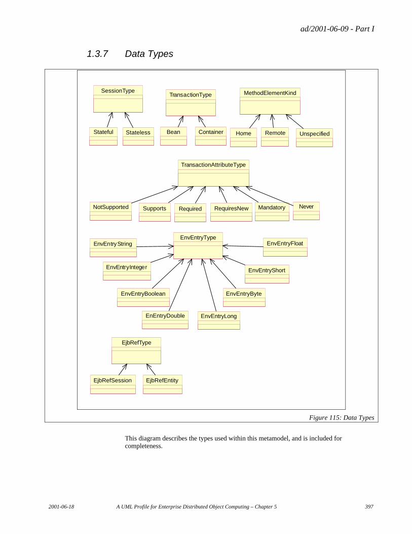
ad/2001-06-09 - Part I
2001-06-18 A UML Profile for Enterprise Distributed Object Computing – Chapter 5 397
1.3.7 Data Types
TransactionType
TransactionAttributeType
MethodElementKind
EnvEntryType
EjbRefType
SessionType
Stateful Stateless Home Remote UnspecifiedBean Container
NotSupported Supports Required RequiresNew Mandatory Never
EjbRefSession EjbRefEntity
EnvEntryString
EnvEntryInteger
EnvEntryBoolean
EnEntryDouble
EnvEntryByte
EnvEntryShort
EnvEntryLong
EnvEntryFloat
Figure 115: Data Types
This diagram describes the types used within this metamodel, and is included for completeness.
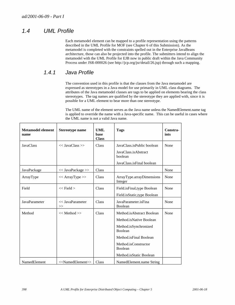
ad/2001-06-09 - Part I
398 A UML Profile for Enterprise Distributed Object Computing – Chapter 5 2001-06-18
1.4 UML Profile
Each metamodel element can be mapped to a profile representation using the patterns described in the UML Profile for MOF (see Chapter 6 of this Submission). As the metamodel is completed with the constraints spelled out in the Enterprise JavaBeans architecture, those can also be projected into the profile. The submitters intend to align the metamodel with the UML Profile for EJB now in public draft within the Java Community Process under JSR-000026 (see http://jcp.org/jsr/detail/26.jsp) through such a mapping.
1.4.1 Java Profile
The convention used in this profile is that the classes from the Java metamodel are expressed as stereotypes in a Java model for use primarily in UML class diagrams. The attributes of the Java metamodel classes are tags to be applied on elements bearing the class stereotypes. The tag names are qualified by the stereotype they are applied with, since it is possible for a UML element to bear more than one stereotype.
The UML name of the element serves as the Java name unless the NamedElement.name tag is applied to override the name with a Java-specific name. This can be useful in cases where the UML name is not a valid Java name.
Metamodel element name
Stereotype name UML base Class
Tags Constra-ints
JavaClass << JavaClass >> Class JavaClass.isPublic boolean
JavaClass.isAbstract boolean
JavaClass.isFinal boolean
None
JavaPackage << JavaPackage >> Class None
ArrayType << ArrayType >> Class ArrayType.arrayDimensions Integer
None
Field << Field > Class Field.isFinal,type Boolean
Field.isStatic,type Boolean
None
JavaParameter << JavaParameter >>
Class JavaParameter.isFina Boolean
None
Method << Method >> Class Method.isAbstract Boolean
Method.isNative Boolean
Method.isSynchronized Boolean
Method.isFinal Boolean
Method.isConstructor Boolean
Method.isStatic Boolean
None
NamedElement <<NamedElement>> Class NamedElement.name String

ad/2001-06-09 - Part I
2001-06-18 A UML Profile for Enterprise Distributed Object Computing – Chapter 5 399
{public, private, protected, package}, type Enumeration
<<Visibility.kind>>
Table 32: Mapping Java Metamodel concepts to profile elements
1.4.2 EJB Profile
This is provided by the UML Profile for EJB now in public draft within the Java Community Process under JSR-000026 (see http://jcp.org/jsr/detail/26.jsp).
ad/2001-06-09 - Part I
400 A UML Profile for Enterprise Distributed Object Computing – Chapter 5 2001-06-18
2. Flow Composition Model
2.1 Introduction
The FCM is a Flow Composition Model (FCM) that can describe the interactions and flows of information between application components in a way that:
• Enables complex actions to be broken down into simple 'flow components' or, alternatively, enables simple entities to be composed into higher level 'flow models'.
• Can be deployed into a variety of runtime environments; in other words, the model treats its components as functional entities which are independent of any specific attributes of a particular deployment, whether that be a workflow, messaging service, etc.
Business applications are commonly made up of interrelated programs. These often run in multiple and different environments. The problem is: how to enable these disparate entities (which may not be directly connected nor running concurrently) to communicate with one another. It can be addressed through the concept of 'messaging' using, for example, MQSeries products. This method of Application Integration enables two (or several) programs to communicate in a relatively simple, static way. The programs, while isolated from each other in a 'time-independent' (asynchronous) fashion, mostly still need to know how to 'speak' to each other.
Each program needs to understand the other's message format; they need to speak the same 'language'. But with a little more sophistication, this need can be removed. A scenario can be created, usually known as Enterprise Application Integration (EAI), whereby messages are transformed into different formats so that programs need know nothing about the eventual recipient of a message. The added sophistication is a mediator between the programs provided by a message 'repository' and a message 'broker' to enable such transforms. Of course, there are other capabilities in brokers beyond transformation but this is probably the most important function.
As the applications become more isolated, the idea of 'routing' can be introduced. Now, another application can observe the content being shared through the broker and choose to modify the information flow. The process handling the information may be relatively long lived - typically the case where human intervention is involved. Also, the information being processed may be stateful (in other words, it persists beyond the scope of the process handling it). Workflow applications provide this sort of functionality and introduces the facility of 'multi-step sequencing'. By using various connectors, these different technologies can, and often are, used together.
The Flow Composition Model is a metamodel for composing complex flows based on invoking operations on components. It is a low-level metamodel focused on the middleware machinery for executing message flows. Higher levels of abstraction can be built upon the FCM for integrating a whole range of technologies and runtime environments:
• Messaging and Message Brokering provide for transformation and routing of information,
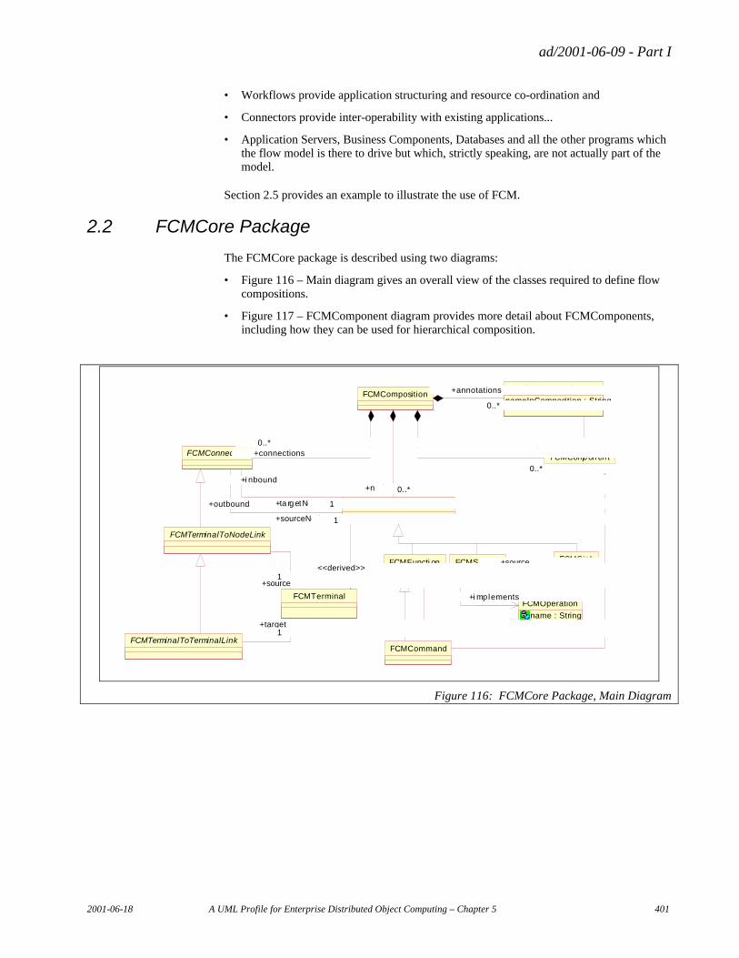
ad/2001-06-09 - Part I
2001-06-18 A UML Profile for Enterprise Distributed Object Computing – Chapter 5 401
• Workflows provide application structuring and resource co-ordination and
• Connectors provide inter-operability with existing applications...
• Application Servers, Business Components, Databases and all the other programs which the flow model is there to drive but which, strictly speaking, are not actually part of the model.
Section 2.5 provides an example to illustrate the use of FCM.
2.2 FCMCore Package
The FCMCore package is described using two diagrams:
• Figure 116 – Main diagram gives an overall view of the classes required to define flow compositions.
• Figure 117 – FCMComponent diagram provides more detail about FCMComponents, including how they can be used for hierarchical composition.
FCMCommand
FCMSinkFCMSource
0..*1
+sink
0..*
+source
1
FCMOperation
name : String
+i mplements
FCMFuncti on
+invokes
FCMComp on en t
1+performedBy 1
FCMAnnotation
nameInComposition : String
1 +annotates1FCMConnection
FCMComposition
0..*
+components
0..*
0..*+connections0..*
0..*
+annotations
0..*
FCMNode
1+sourceNode 1
+outbound 1+ta rg etNo de 1
+i nbound0..*+nodes 0..*
FCMTerminalToNodeLink
FCMTerminalToTerminalLink
FCMTerminal
0..*+interface 0..*
<<derived>>
1+target
1
1+source
1
Figure 116: FCMCore Package, Main Diagram
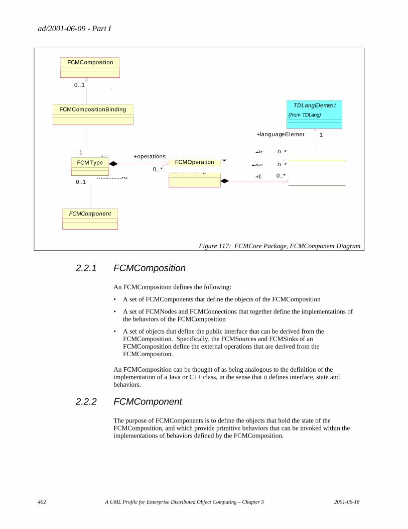
ad/2001-06-09 - Part I
402 A UML Profile for Enterprise Distributed Object Computing – Chapter 5 2001-06-18
FCMCompositionBinding
FCMComposition
TDLangElemen t
(from TDLang)
FCMComponent
0..1 +composition0..1
FCMParameter
1+languageElement 1
FCMType
0..1 +instanceOf0..1
1 +type1
FCMOperation
name : String0..*+faults 0..*
0..*+outputs 0..*
0..*+inputs 0..*
0.. *
+operations
0.. *
Figure 117: FCMCore Package, FCMComponent Diagram
2.2.1 FCMComposition
An FCMComposition defines the following:
• A set of FCMComponents that define the objects of the FCMComposition
• A set of FCMNodes and FCMConnections that together define the implementations of the behaviors of the FCMComposition
• A set of objects that define the public interface that can be derived from the FCMComposition. Specifically, the FCMSources and FCMSinks of an FCMComposition define the external operations that are derived from the FCMComposition.
An FCMComposition can be thought of as being analogous to the definition of the implementation of a Java or C++ class, in the sense that it defines interface, state and behaviors.
2.2.2 FCMComponent
The purpose of FCMComponents is to define the objects that hold the state of the FCMComposition, and which provide primitive behaviors that can be invoked within the implementations of behaviors defined by the FCMComposition.
ad/2001-06-09 - Part I
2001-06-18 A UML Profile for Enterprise Distributed Object Computing – Chapter 5 403
2.2.3 FCMNode
An FCMNode represents a fragment of flow logic. It can be thought of as being analogous to a statement or contiguous sequence of statements in a programming language. FCMNodes are used to define the implementations of behaviors of the FCMComposition. FCMNodes are connected together in a graph using FCMConnections to build up more complex behaviors of the FCMComposition.
FCMNodes are represented as “nodes” or icons in flow diagrams.
2.2.4 FCMConnection
An FCMConnection is an object that specifies a relationship between two FCMNodes. Examples of FCMConnections are FCMControlLinks and FCMDataLinks (see the FCM Package, FCMConnections diagram). FCMConnections provide directed links between FCMNodes in a graph to specify more complex behaviors. The number and type of FCMConnections is extensible – the Flow Composition Model puts no constraints on this.
FCMConnections are represented in flow diagrams as lines that connect the icons representing FCMNodes.
2.2.5 FCMOperation
An FCMOperation defines the interface to an FCMNode, including its signature. An example specialization of FCMOperation is a WSDL (Web Services Definition Language) Operation, which defines an optional input message, an optional output message and optional fault messages.
2.2.6 FCMParameter
FCMParameters identify the signature of an FCMOperation, which can include inputs, outputs and faults. For a WSDL Operation, an FCMParameter provides the abstract definition of a message. FCMParameter is a specialization of TDLangElement, which provides the linkage to the language specific and physical representations of the data that an FCMParameter represents.
2.2.7 FCMCommand
An FCMCommand is a special kind of FCMNode that represents the invocation of a particular FCMOperation on an FCMComponent. An FCMCommand can be thought of as being analogous to a programming language statement that invokes a method on an object.
2.2.8 FCMFunction
An FCMFunction is a special kind of FCMNode. It’s similar to an FCMCommand in that it represents the invocation of a particular FCMOperation. However, in this case the FCMOperation does not have an FCMComponent associated with it. An FCMFunction can be thought of as being analogous to a programming language statement that makes a procedural call or invokes a transaction.
ad/2001-06-09 - Part I
404 A UML Profile for Enterprise Distributed Object Computing – Chapter 5 2001-06-18
2.2.9 FCMTerminal
FCMTerminals provide a mechanism for identifying the interfaces to an FCMNode. They are derived, with the derivation based on the type of FCMNode they are associated with. For example, an FCMNode that represents the invocation of a WSDL operation will have FCMTerminals that are derived one for one from the parameters of the operation. An FCMMappingNode (in the FCM package) will have one input terminal for each piece of input data, and one output terminal for each output (typically one, formed by combining the inputs in some way). FCMJoinNodes and FCMBranchNodes (in the FCM package) have no terminals.
2.2.10 FCMTerminalToNodeLink and FCMTerminalToTerminalLink
These are abstract specializations of FCMConnection.
An FCMTerminalToNodeLink represents an FCMConnection from a particular outcome of a source FCMNode to a target FCMNode. The “source” association identifies which outcome to use as the source of the FCMTerminalToNodeLink. FCMControlLinks (in the FCM package) are concrete examples of FCMTerminalToNodeLinks.
FCMTerminalToTerminalLink is a specialization of FCMTerminalToNodeLink that in addition specifies the particular input of the target FCMNode to connect to. This is indentified by the “target” association. FCMDataLinks (in the FCM package) are concrete examples of FCMTerminalToTerminalLinks.
2.2.11 FCMAnnotation
An important design goal of the Flow Composition Model is the ability to be able to work with FCMComponents of pre-defined types that were not designed with the specific needs of the Flow Composition Model in mind. This means that the Flow Composition Model cannot require FCMComponents to support special attributes or behaviors in order to participate in Flow Compositions. In order to satisfy this requirement, the Flow Composition Model allows an FCMAnnotation object to be associated with each FCMComponent. An FCMAnnotation is an object that is used to carry information about an FCMComponent that is useful or necessary in the context of a Flow, but which is not a property of the FCMComponent itself. A common example is that every FCMComponent must have a name associated with it to identify it within the FCMComposition, even though not all FCMComponents have a name property.
2.2.12 FCMSource and FCMSink
FCMSources and FCMSinks are special FCMNodes that are used to define the FCMOperations available on the public interface that can be derived from an FCMComposition. An FCMSource represents an entry point into the behaviors defined by an FCMComposition. An FCMSource within an FCMComposition corresponds to a One-way or Request-Response operation defined on the external interface defined by the FCMComposition. An FCMSource can act only as a sourceNode for an FCMConnection. The source FCMTerminal for the FCMConnection is derived from the input FCMParameter of the FCMOperation that the FCMSource implements.
An FCMSource may have associated with it a corresponding FCMSink. An FCMSink is an FCMNode that defines the output and fault FCMParameters of the FCMOperation
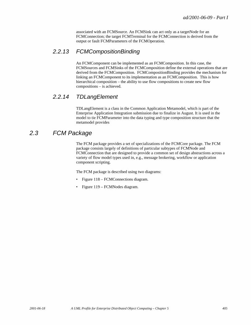
ad/2001-06-09 - Part I
2001-06-18 A UML Profile for Enterprise Distributed Object Computing – Chapter 5 405
associated with an FCMSource. An FCMSink can act only as a targetNode for an FCMConnection; the target FCMTerminal for the FCMConnection is derived from the output or fault FCMParameters of the FCMOperation.
2.2.13 FCMCompositionBinding
An FCMComponent can be implemented as an FCMComposition. In this case, the FCMSources and FCMSinks of the FCMComposition define the external operations that are derived from the FCMComposition. FCMCompositionBinding provides the mechanism for linking an FCMComponent to its implementation as an FCMComposition. This is how hierarchical composition – the ability to use flow compositions to create new flow compositions – is achieved.
2.2.14 TDLangElement
TDLangElement is a class in the Common Application Metamodel, which is part of the Enterprise Application Integration submission due to finalize in August. It is used in the model to tie FCMParameter into the data typing and type composition structure that the metamodel provides
2.3 FCM Package
The FCM package provides a set of specializations of the FCMCore package. The FCM package consists largely of definitions of particular subtypes of FCMNode and FCMConnection that are designed to provide a common set of design abstractions across a variety of flow model types used in, e.g., message brokering, workflow or application component scripting.
The FCM package is described using two diagrams:
• Figure 118 – FCMConnections diagram.
• Figure 119 – FCMNodes diagram.
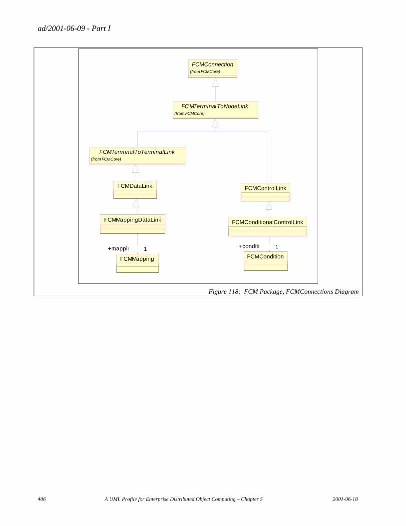
ad/2001-06-09 - Part I
406 A UML Profile for Enterprise Distributed Object Computing – Chapter 5 2001-06-18
FCMConnection(from FCMCore)
FCMTerminalToNodeLink(from FCMCore)
FCMTerminalToTerminalLink(from FCMCore)
FCMMapping
FCMMappingDataLink
1+mapping 1FCMCondition
FCMConditionalControlLink
1+condition 1
FCMDataLink FCMControlLink
Figure 118: FCM Package, FCMConnections Diagram
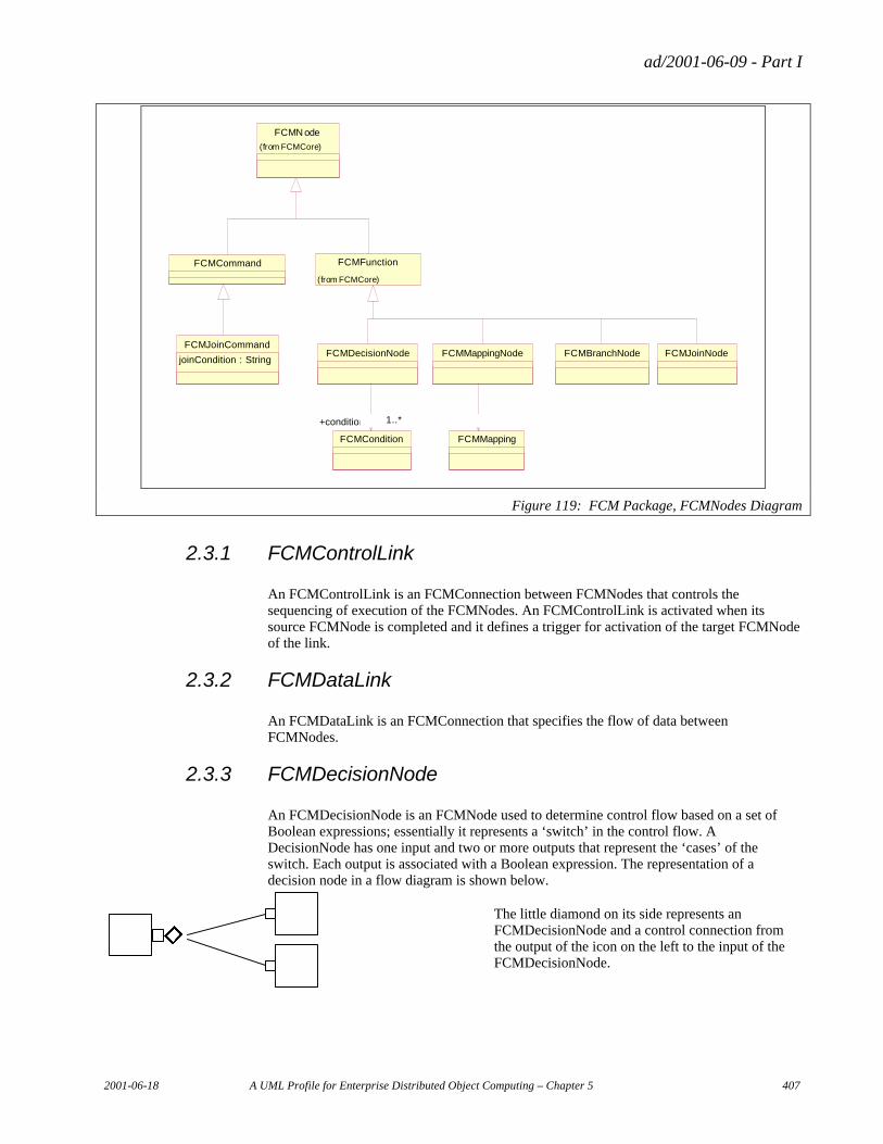
ad/2001-06-09 - Part I
2001-06-18 A UML Profile for Enterprise Distributed Object Computing – Chapter 5 407
FCMN ode
(from FCMCore)
FCMJoinNodeFCMBranchNode
FCMMapping
FCMMappingNode
0..*0..*
FCMCondition
FCMDecisionNode
1..*+condition 1..*
FCMCommand
FCMJoinCommand
joinCondition : String
FCMFunction
(from FCMCore)
Figure 119: FCM Package, FCMNodes Diagram
2.3.1 FCMControlLink
An FCMControlLink is an FCMConnection between FCMNodes that controls the sequencing of execution of the FCMNodes. An FCMControlLink is activated when its source FCMNode is completed and it defines a trigger for activation of the target FCMNode of the link.
2.3.2 FCMDataLink
An FCMDataLink is an FCMConnection that specifies the flow of data between FCMNodes.
2.3.3 FCMDecisionNode
An FCMDecisionNode is an FCMNode used to determine control flow based on a set of Boolean expressions; essentially it represents a ‘switch’ in the control flow. A DecisionNode has one input and two or more outputs that represent the ‘cases’ of the switch. Each output is associated with a Boolean expression. The representation of a decision node in a flow diagram is shown below.
The little diamond on its side represents an FCMDecisionNode and a control connection from the output of the icon on the left to the input of the FCMDecisionNode.
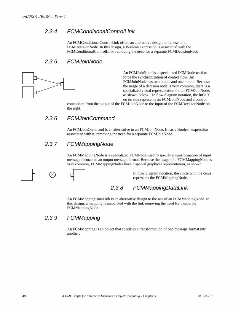
ad/2001-06-09 - Part I
408 A UML Profile for Enterprise Distributed Object Computing – Chapter 5 2001-06-18
2.3.4 FCMConditionalControlLink
An FCMConditionalControlLink offers an alternative design to the use of an FCMDecisionNode. In this design, a Boolean expression is associated with the FCMConditionalControlLink, removing the need for a separate FCMDecisionNode.
2.3.5 FCMJoinNode
An FCMJoinNode is a specialized FCMNode used to force the synchronization of control flow. An FCMJoinNode has two inputs and one output. Because the usage of a decision node is very common, there is a specialized visual representation for an FCMJoinNode, as shown below. In flow diagram notation, the little T on its side represents an FCMJoinNode and a control
connection from the output of the FCMJoinNode to the input of the FCMDecisionNode on the right.
2.3.6 FCMJoinCommand
An FCMJoinCommand is an alternative to an FCMJoinNode. It has a Boolean expression associated with it, removing the need for a separate FCMJoinNode.
2.3.7 FCMMappingNode
An FCMMappingNode is a specialized FCMNode used to specify a transformation of input message formats to an output message format. Because the usage of a FCMMappingNode is very common, FCMMappingNodes have a special graphical representation, as shown.
In flow diagram notation, the circle with the cross represents the FCMMappingNode.
2.3.8 FCMMappingDataLink
An FCMMappingDataLink is an alternative design to the use of an FCMMappingNode. In this design, a mapping is associated with the link removing the need for a separate FCMMappingNode.
2.3.9 FCMMapping
An FCMMapping is an object that specifies a transformation of one message format into another.
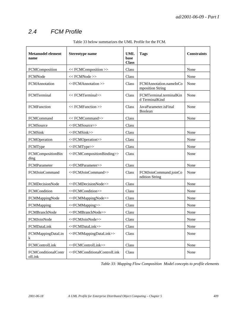
ad/2001-06-09 - Part I
2001-06-18 A UML Profile for Enterprise Distributed Object Computing – Chapter 5 409
2.4 FCM Profile
Table 33 below summarizes the UML Profile for the FCM.
Metamodel element name
Stereotype name UML base Class
Tags Constraints
FCMComposition << FCMComposition >> Class None
FCMNode << FCMNode >> Class None
FCMAnnotation <<FCMAnnotation >> Class FCMAnnotation.nameInComposition String
None
FCMTerminal << FCMTerminal>> Class FCMTerminal.terminalKind TerminalKind
None
FCMFunction << FCMFunction >> Class JavaParameter.isFinal Boolean
None
FCMCommand << FCMCommand>> Class None
FCMSource <<FCMSource>> Class
FCMSink <<FCMSink>> Class None
FCMOperation <<FCMOperation>> Class None
FCMType <<FCMType>> Class None
FCMCompositionBinding
<<FCMCompositionBinding>> Class None
FCMParameter <<FCMParameter>> Class None
FCMJoinCommand <<FCMJoinCommand>> Class FCMJoinCommand.joinCondition String
None
FCMDecisionNode <<FCMDecisionNode>> Class None
FCMCondition <<FCMCondition>> Class None
FCMMappingNode <<FCMMappingNode>> Class None
FCMMapping <<FCMMapping>> Class None
FCMBranchNode <<FCMBranchNode>> Class None
FCMJoinNode <<FCMJoinNode>> Class None
FCMDataLink <<FCMDataLink>> Class None
FCMMappingDataLink
<<FCMMappingDataLink>> Class None
FCMControlLink <<FCMControlLink>> Class None
FCMConditionalControlLink
<<FCMConditionalControlLink Class None
Table 33: Mapping Flow Composition Model concepts to profile elements
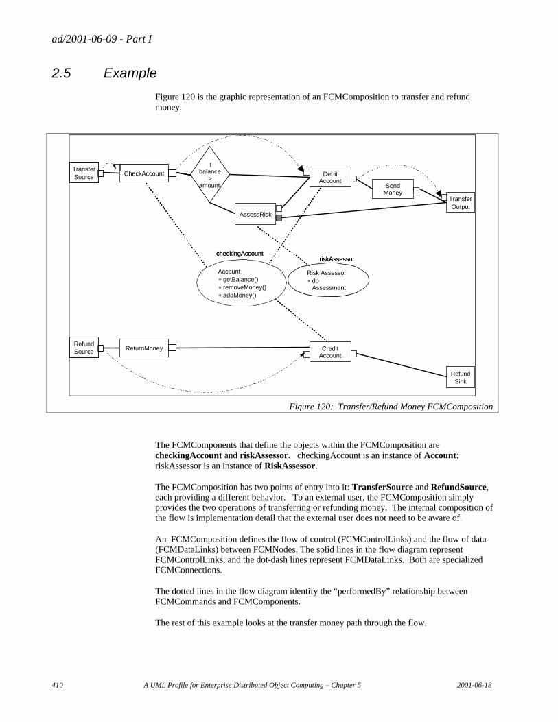
ad/2001-06-09 - Part I
410 A UML Profile for Enterprise Distributed Object Computing – Chapter 5 2001-06-18
2.5 Example
Figure 120 is the graphic representation of an FCMComposition to transfer and refund money.
if balance
> amount
Risk Assessordo Assessment
TransferInput CheckAccount
Send Money
TransferOutput
checkingAccountriskAssessor
if balance
> amount
AccountgetBalance()removeMoney()addMoney()
Risk Assessordo Assessment
TransferSource CheckAccount
AssessRisk
Debit Account
checkingAccountriskAssessor
TransferInput CheckAccount
RefundSink
Credit Account
RefundSource ReturnMoney
Figure 120: Transfer/Refund Money FCMComposition
The FCMComponents that define the objects within the FCMComposition are checkingAccount and riskAssessor. checkingAccount is an instance of Account; riskAssessor is an instance of RiskAssessor.
The FCMComposition has two points of entry into it: TransferSource and RefundSource, each providing a different behavior. To an external user, the FCMComposition simply provides the two operations of transferring or refunding money. The internal composition of the flow is implementation detail that the external user does not need to be aware of.
An FCMComposition defines the flow of control (FCMControlLinks) and the flow of data (FCMDataLinks) between FCMNodes. The solid lines in the flow diagram represent FCMControlLinks, and the dot-dash lines represent FCMDataLinks. Both are specialized FCMConnections.
The dotted lines in the flow diagram identify the “performedBy” relationship between FCMCommands and FCMComponents.
The rest of this example looks at the transfer money path through the flow.
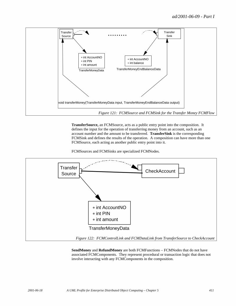
ad/2001-06-09 - Part I
2001-06-18 A UML Profile for Enterprise Distributed Object Computing – Chapter 5 411
void transferMoney(TransferMoneyData input, TransferMoneyEndBalanceData output)
int AccountNOint PINint amount
TransferMoneyData
int AccountNOint balance
TransferMoneyEndBalanceData
TransferSource
TransferSink.........
Figure 121: FCMSource and FCMSink for the Transfer Money FCMFlow
TransferSource, an FCMSource, acts as a public entry point into the composition. It defines the input for the operation of transferring money from an account, such as an account number and the amount to be transferred. TransferSink is the corresponding FCMSink and defines the results of the operation. A composition can have more than one FCMSource, each acting as another public entry point into it.
FCMSources and FCMSinks are specialized FCMNodes.
int AccountNOint PINint amount
TransferMoneyData
TransferSource
CheckAccount
Figure 122: FCMControlLink and FCMDataLink from TransferSource to CheckAccount
SendMoney and RefundMoney are both FCMFunctions – FCMNodes that do not have associated FCMComponents. They represent procedural or transaction logic that does not involve interacting with any FCMComponents in the composition.
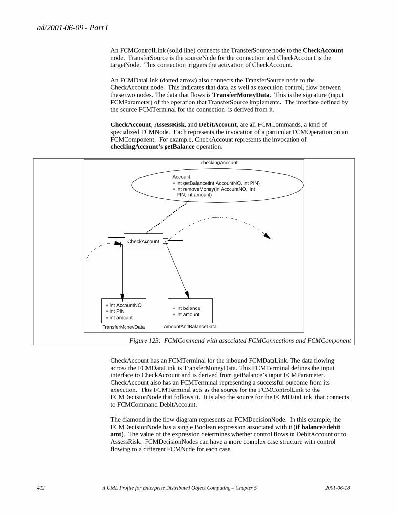
ad/2001-06-09 - Part I
412 A UML Profile for Enterprise Distributed Object Computing – Chapter 5 2001-06-18
An FCMControlLink (solid line) connects the TransferSource node to the CheckAccount node. TransferSource is the sourceNode for the connection and CheckAccount is the targetNode. This connection triggers the activation of CheckAccount.
An FCMDataLink (dotted arrow) also connects the TransferSource node to the CheckAccount node. This indicates that data, as well as execution control, flow between these two nodes. The data that flows is TransferMoneyData. This is the signature (input FCMParameter) of the operation that TransferSource implements. The interface defined by the source FCMTerminal for the connection is derived from it.
CheckAccount, AssessRisk, and DebitAccount, are all FCMCommands, a kind of specialized FCMNode. Each represents the invocation of a particular FCMOperation on an FCMComponent. For example, CheckAccount represents the invocation of checkingAccount’s getBalance operation.
Accountint getBalance(int AccountNO, int PIN)int removeMoney(in AccountNO, int PIN, int amount)
CheckAccount
checkingAccount
int AccountNOint PINint amount
TransferMoneyData
int balanceint amount
AmountAndBalanceData
Figure 123: FCMCommand with associated FCMConnections and FCMComponent
CheckAccount has an FCMTerminal for the inbound FCMDataLink. The data flowing across the FCMDataLink is TransferMoneyData. This FCMTerminal defines the input interface to CheckAccount and is derived from getBalance’s input FCMParameter. CheckAccount also has an FCMTerminal representing a successful outcome from its execution. This FCMTerminal acts as the source for the FCMControlLink to the FCMDecisionNode that follows it. It is also the source for the FCMDataLink that connects to FCMCommand DebitAccount.
The diamond in the flow diagram represents an FCMDecisionNode. In this example, the FCMDecisionNode has a single Boolean expression associated with it (if balance>debit amt). The value of the expression determines whether control flows to DebitAccount or to AssessRisk. FCMDecisionNodes can have a more complex case structure with control flowing to a different FCMNode for each case.
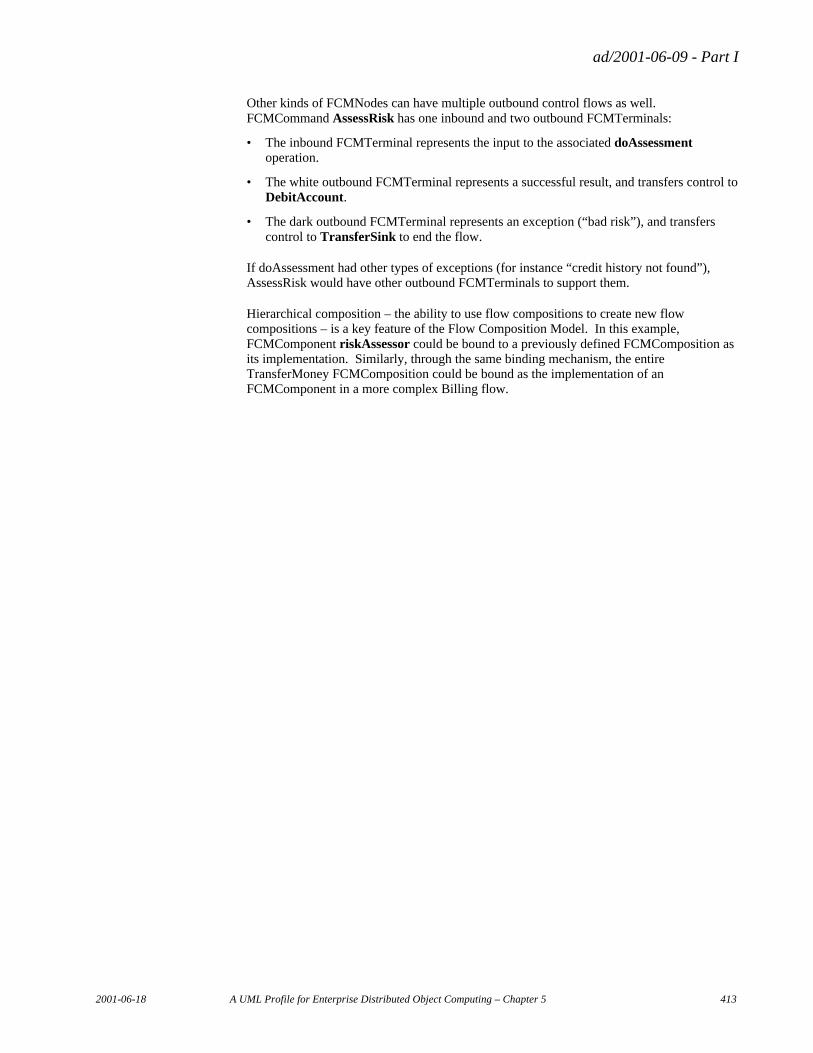
ad/2001-06-09 - Part I
2001-06-18 A UML Profile for Enterprise Distributed Object Computing – Chapter 5 413
Other kinds of FCMNodes can have multiple outbound control flows as well. FCMCommand AssessRisk has one inbound and two outbound FCMTerminals:
• The inbound FCMTerminal represents the input to the associated doAssessment operation.
• The white outbound FCMTerminal represents a successful result, and transfers control to DebitAccount.
• The dark outbound FCMTerminal represents an exception (“bad risk”), and transfers control to TransferSink to end the flow.
If doAssessment had other types of exceptions (for instance “credit history not found”), AssessRisk would have other outbound FCMTerminals to support them.
Hierarchical composition – the ability to use flow compositions to create new flow compositions – is a key feature of the Flow Composition Model. In this example, FCMComponent riskAssessor could be bound to a previously defined FCMComposition as its implementation. Similarly, through the same binding mechanism, the entire TransferMoney FCMComposition could be bound as the implementation of an FCMComponent in a more complex Billing flow.

ad/2001-06-09 - Part I
2001-06-18 A UML Profile for Enterprise Distributed Object Computing – Chapter 6 415
Chapter 6 UML Profile for MOF
Table of Contents
1. Introduction................................................................................................................................................... 418
2. UML-to-MOF Mapping Table ...................................................................................................................... 419
3. Mapping Details ............................................................................................................................................ 420 3.1 ModelElement ...................................................................................................................................... 420
3.1.1 Tags on UML ModelElement ..................................................................................................... 420 3.1.2 ModelElement Property Map...................................................................................................... 420 3.1.3 ModelElement Constraints.......................................................................................................... 420 3.1.4 ModelElement Limitations.......................................................................................................... 421
3.2 Package................................................................................................................................................. 421 3.2.1 Tags on UML Model with Stereotype <<metamodel>> ............................................................. 421 3.2.2 Model-to-Package Property Map ................................................................................................ 421 3.2.3 Model-to-Package Constraints .................................................................................................... 421 3.2.4 Model-to-Package Limitations .................................................................................................... 422
3.3 Import ................................................................................................................................................... 422 3.3.1 Tags on UML ElementImport ..................................................................................................... 422 3.3.2 ElementImport-to-Import Property Map ..................................................................................... 422 3.3.3 ElementImport-to-Import Constraints ......................................................................................... 422 3.3.4 ElementImport-to-Import Limitations......................................................................................... 422
3.4 Class ..................................................................................................................................................... 422 3.4.1 Tags on UML Class .................................................................................................................... 422 3.4.2 Class Property Map..................................................................................................................... 423 3.4.3 Class Constraints......................................................................................................................... 423 3.4.4 Class Limitations......................................................................................................................... 423
3.5 Attribute................................................................................................................................................ 423 3.5.1 Tags on UML Attribute with No Stereotype ............................................................................... 423 3.5.2 Attribute Property Map ............................................................................................................... 423 3.5.3 Attribute Constraints ................................................................................................................... 424 3.5.4 Attribute Limitations ................................................................................................................... 424
3.6 Reference.............................................................................................................................................. 424 3.6.1 Tags on UML Attribute with Stereotype <<reference>> ............................................................ 424 3.6.2 Explicit Reference Property Map................................................................................................ 424 3.6.3 Implicit Reference Property Map................................................................................................ 424 3.6.4 Reference Constraints ................................................................................................................. 425 3.6.5 Reference Limitations ................................................................................................................. 425
3.7 Operation.............................................................................................................................................. 425 3.7.1 Tags on UML Operation ............................................................................................................. 425 3.7.2 Operation Property Map ............................................................................................................. 425 3.7.3 Operation Constraints ................................................................................................................. 426 3.7.4 Operation Limitations ................................................................................................................. 426
ad/2001-06-09 - Part I
416 A UML Profile for Enterprise Distributed Object Computing – Chapter 6 2001-06-18
3.8 Parameter.............................................................................................................................................. 426 3.8.1 Tags on UML Parameter............................................................................................................. 426 3.8.2 Parameter Property Map ............................................................................................................. 426 3.8.3 Parameter Constraints ................................................................................................................. 426 3.8.4 Parameter Limitations ................................................................................................................. 426
3.9 Exception.............................................................................................................................................. 426 3.9.1 Tags on UML Exception............................................................................................................. 427 3.9.2 Exception Property Map ............................................................................................................. 427 3.9.3 Exception Constraints ................................................................................................................. 427 3.9.4 Exception Limitations ................................................................................................................. 427
3.10 Exception Parameter............................................................................................................................. 427 3.10.1 Tags on Attribute of UML Exception ......................................................................................... 427 3.10.2 Attribute-to-Parameter Property Map ......................................................................................... 427 3.10.3 Attribute-to-Parameter Constraints ............................................................................................. 427 3.10.4 Attribute-to-Parameter Limitations ............................................................................................. 427
3.11 Association ........................................................................................................................................... 428 3.11.1 Tags on UML Association .......................................................................................................... 428 3.11.2 Association Property Map........................................................................................................... 428 3.11.3 Association Constraints............................................................................................................... 428 3.11.4 Association Limitations............................................................................................................... 428
3.12 AssociationEnd..................................................................................................................................... 428 3.12.1 Tags on UML AssociationEnd.................................................................................................... 428 3.12.2 AssociationEnd Property Map .................................................................................................... 428 3.12.3 AssociationEnd Constraints ........................................................................................................ 429 3.12.4 AssociationEnd Limitations ........................................................................................................ 429
3.13 DataType .............................................................................................................................................. 429 3.13.1 Tags on UML DataType ............................................................................................................. 429 3.13.2 DataType Property Map.............................................................................................................. 429 3.13.3 DataType Constraints.................................................................................................................. 430 3.13.4 DataType Limitations.................................................................................................................. 430
3.14 Constant................................................................................................................................................ 430 3.14.1 Tags on UML DataValue ............................................................................................................ 430 3.14.2 DataValue-to-Constant Property Map......................................................................................... 430 3.14.3 DataValue-to-Constant Constraints............................................................................................. 430 3.14.4 DataValue-to-Constant Limitations............................................................................................. 430
3.15 Constraint ............................................................................................................................................. 430 3.15.1 Tags on UML Constraint ............................................................................................................ 430 3.15.2 Constraint Property Map............................................................................................................. 431 3.15.3 Constraint Constraints ................................................................................................................. 431 3.15.4 Constraint Limitations................................................................................................................. 431
3.16 Generalizes ........................................................................................................................................... 431 3.16.1 Tags on UML Generalization...................................................................................................... 431 3.16.2 Generalization-to-Generalizes Property Map.............................................................................. 431 3.16.3 Generalization-to-Generalizes Constraints.................................................................................. 431 3.16.4 Generalization-to-Generalizes Limitations.................................................................................. 431
3.17 Tag........................................................................................................................................................ 431 3.17.1 Tags on UML TaggedValue........................................................................................................ 432 3.17.2 TaggedValue-to-Tag Property Map ............................................................................................ 432 3.17.3 TaggedValue-to-Tag Constraints ................................................................................................ 432 3.17.4 TaggedValue-to-Tag Limitations ................................................................................................ 432
4. Guidelines ..................................................................................................................................................... 433 4.1 Modularity ............................................................................................................................................ 433 4.2 Associations.......................................................................................................................................... 433 4.3 References ............................................................................................................................................ 434 4.4 DataTypes............................................................................................................................................. 434 4.5 Names................................................................................................................................................... 434

ad/2001-06-09 - Part I
2001-06-18 A UML Profile for Enterprise Distributed Object Computing – Chapter 6 417
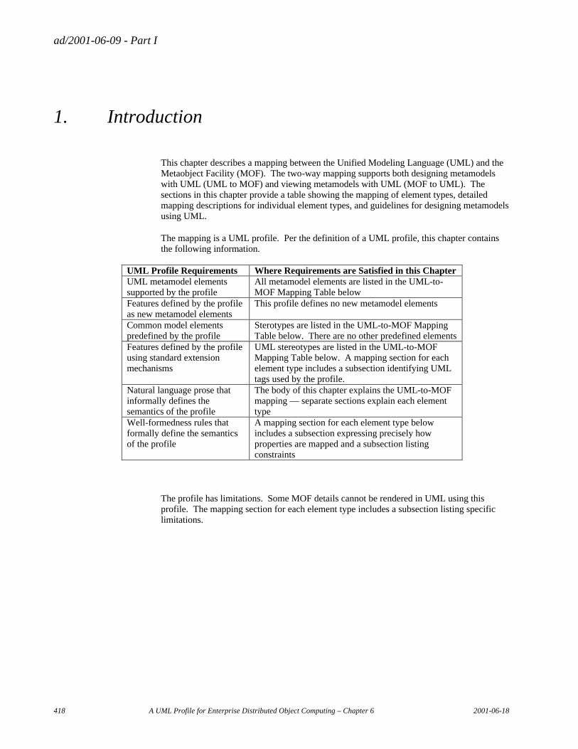
ad/2001-06-09 - Part I
418 A UML Profile for Enterprise Distributed Object Computing – Chapter 6 2001-06-18
1. Introduction
This chapter describes a mapping between the Unified Modeling Language (UML) and the Metaobject Facility (MOF). The two-way mapping supports both designing metamodels with UML (UML to MOF) and viewing metamodels with UML (MOF to UML). The sections in this chapter provide a table showing the mapping of element types, detailed mapping descriptions for individual element types, and guidelines for designing metamodels using UML.
The mapping is a UML profile. Per the definition of a UML profile, this chapter contains the following information.
UML Profile Requirements Where Requirements are Satisfied in this Chapter UML metamodel elements supported by the profile
All metamodel elements are listed in the UML-to-MOF Mapping Table below
Features defined by the profile as new metamodel elements
This profile defines no new metamodel elements
Common model elements predefined by the profile
Sterotypes are listed in the UML-to-MOF Mapping Table below. There are no other predefined elements
Features defined by the profile using standard extension mechanisms
UML stereotypes are listed in the UML-to-MOF Mapping Table below. A mapping section for each element type includes a subsection identifying UML tags used by the profile.
Natural language prose that informally defines the semantics of the profile
The body of this chapter explains the UML-to-MOF mapping — separate sections explain each element type
Well-formedness rules that formally define the semantics of the profile
A mapping section for each element type below includes a subsection expressing precisely how properties are mapped and a subsection listing constraints
The profile has limitations. Some MOF details cannot be rendered in UML using this profile. The mapping section for each element type includes a subsection listing specific limitations.
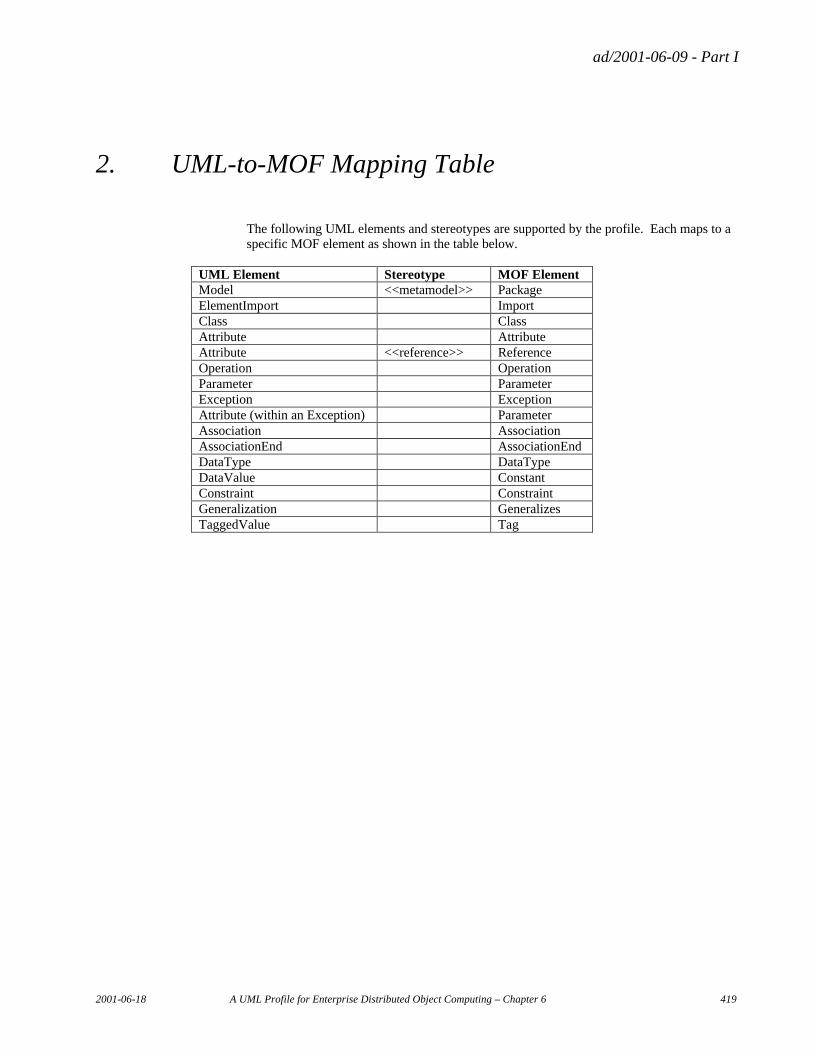
ad/2001-06-09 - Part I
2001-06-18 A UML Profile for Enterprise Distributed Object Computing – Chapter 6 419
2. UML-to-MOF Mapping Table
The following UML elements and stereotypes are supported by the profile. Each maps to a specific MOF element as shown in the table below.
UML Element Stereotype MOF Element Model <<metamodel>> Package ElementImport Import Class Class Attribute Attribute Attribute <<reference>> Reference Operation Operation Parameter Parameter Exception Exception Attribute (within an Exception) Parameter Association Association AssociationEnd AssociationEnd DataType DataType DataValue Constant Constraint Constraint Generalization Generalizes TaggedValue Tag
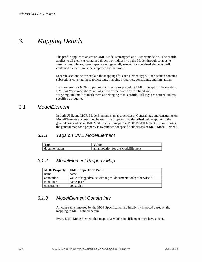
ad/2001-06-09 - Part I
420 A UML Profile for Enterprise Distributed Object Computing – Chapter 6 2001-06-18
3. Mapping Details
The profile applies to an entire UML Model stereotyped as a <<metamodel>>. The profile applies to all elements contained directly or indirectly by the Model through composite associations. Hence, stereotypes are not generally needed for contained elements. All contained elements must be supported by the profile.
Separate sections below explain the mappings for each element type. Each section contains subsections covering these topics: tags, mapping properties, constraints, and limitations.
Tags are used for MOF properties not directly supported by UML. Except for the standard UML tag “documentation”, all tags used by the profile are prefixed with “org.omg.uml2mof” to mark them as belonging to this profile. All tags are optional unless specified as required.
3.1 ModelElement
In both UML and MOF, ModelElement is an abstract class. General tags and constraints on ModelElements are described below. The property map described below applies to the general cases where a UML ModelElement maps to a MOF ModelElement. In some cases the general map for a property is overridden for specific subclasses of MOF ModelElement.
3.1.1 Tags on UML ModelElement
Tag Value documentation an annotation for the ModelElement
3.1.2 ModelElement Property Map
MOF Property UML Property or Value name name annotation value of taggedValue with tag = “documentation”; otherwise “” container namespace constraints constraint
3.1.3 ModelElement Constraints
All constraints imposed by the MOF Specification are implicitly imposed based on the mapping to MOF defined herein.
Every UML ModelElement that maps to a MOF ModelElement must have a name.
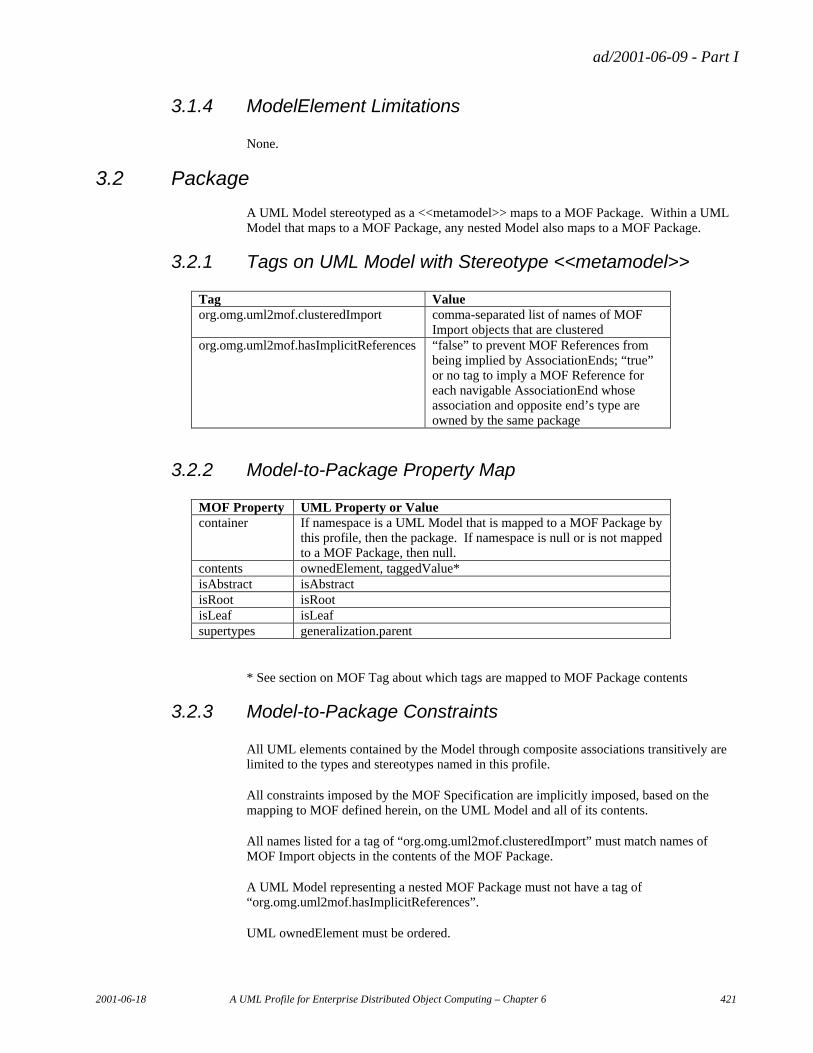
ad/2001-06-09 - Part I
2001-06-18 A UML Profile for Enterprise Distributed Object Computing – Chapter 6 421
3.1.4 ModelElement Limitations
None.
3.2 Package
A UML Model stereotyped as a <<metamodel>> maps to a MOF Package. Within a UML Model that maps to a MOF Package, any nested Model also maps to a MOF Package.
3.2.1 Tags on UML Model with Stereotype <<metamodel>>
Tag Value org.omg.uml2mof.clusteredImport comma-separated list of names of MOF
Import objects that are clustered org.omg.uml2mof.hasImplicitReferences “false” to prevent MOF References from
being implied by AssociationEnds; “true” or no tag to imply a MOF Reference for each navigable AssociationEnd whose association and opposite end’s type are owned by the same package
3.2.2 Model-to-Package Property Map
MOF Property UML Property or Value container If namespace is a UML Model that is mapped to a MOF Package by
this profile, then the package. If namespace is null or is not mapped to a MOF Package, then null.
contents ownedElement, taggedValue* isAbstract isAbstract isRoot isRoot isLeaf isLeaf supertypes generalization.parent
* See section on MOF Tag about which tags are mapped to MOF Package contents
3.2.3 Model-to-Package Constraints
All UML elements contained by the Model through composite associations transitively are limited to the types and stereotypes named in this profile.
All constraints imposed by the MOF Specification are implicitly imposed, based on the mapping to MOF defined herein, on the UML Model and all of its contents.
All names listed for a tag of “org.omg.uml2mof.clusteredImport” must match names of MOF Import objects in the contents of the MOF Package.
A UML Model representing a nested MOF Package must not have a tag of “org.omg.uml2mof.hasImplicitReferences”.
UML ownedElement must be ordered.
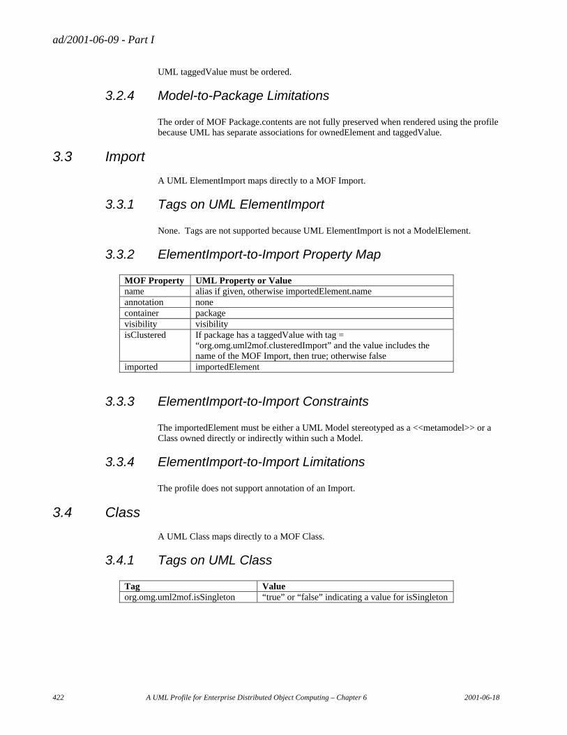
ad/2001-06-09 - Part I
422 A UML Profile for Enterprise Distributed Object Computing – Chapter 6 2001-06-18
UML taggedValue must be ordered.
3.2.4 Model-to-Package Limitations
The order of MOF Package.contents are not fully preserved when rendered using the profile because UML has separate associations for ownedElement and taggedValue.
3.3 Import
A UML ElementImport maps directly to a MOF Import.
3.3.1 Tags on UML ElementImport
None. Tags are not supported because UML ElementImport is not a ModelElement.
3.3.2 ElementImport-to-Import Property Map
MOF Property UML Property or Value name alias if given, otherwise importedElement.name annotation none container package visibility visibility isClustered If package has a taggedValue with tag =
“org.omg.uml2mof.clusteredImport” and the value includes the name of the MOF Import, then true; otherwise false
imported importedElement
3.3.3 ElementImport-to-Import Constraints
The importedElement must be either a UML Model stereotyped as a <<metamodel>> or a Class owned directly or indirectly within such a Model.
3.3.4 ElementImport-to-Import Limitations
The profile does not support annotation of an Import.
3.4 Class
A UML Class maps directly to a MOF Class.
3.4.1 Tags on UML Class
Tag Value org.omg.uml2mof.isSingleton “true” or “false” indicating a value for isSingleton
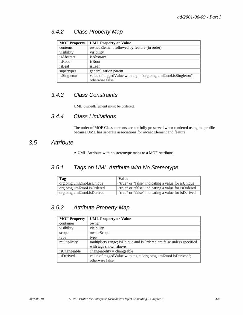
ad/2001-06-09 - Part I
2001-06-18 A UML Profile for Enterprise Distributed Object Computing – Chapter 6 423
3.4.2 Class Property Map
MOF Property UML Property or Value contents ownedElement followed by feature (in order) visibility visibility isAbstract isAbstract isRoot isRoot isLeaf isLeaf supertypes generalization.parent isSingleton value of taggedValue with tag = “org.omg.uml2mof.isSingleton”;
otherwise false
3.4.3 Class Constraints
UML ownedElement must be ordered.
3.4.4 Class Limitations
The order of MOF Class.contents are not fully preserved when rendered using the profile because UML has separate associations for ownedElement and feature.
3.5 Attribute
A UML Attribute with no stereotype maps to a MOF Attribute.
3.5.1 Tags on UML Attribute with No Stereotype
Tag Value org.omg.uml2mof.isUnique “true” or “false” indicating a value for isUnique org.omg.uml2mof.isOrdered “true” or “false” indicating a value for isOrdered org.omg.uml2mof.isDerived “true” or “false” indicating a value for isDerived
3.5.2 Attribute Property Map
MOF Property UML Property or Value container owner visibility visibility scope ownerScope type type multiplicity multiplicty.range; isUnique and isOrdered are false unless specified
with tags shown above isChangeable changeability = changeable isDerived value of taggedValue with tag = “org.omg.uml2mof.isDerived”;
otherwise false
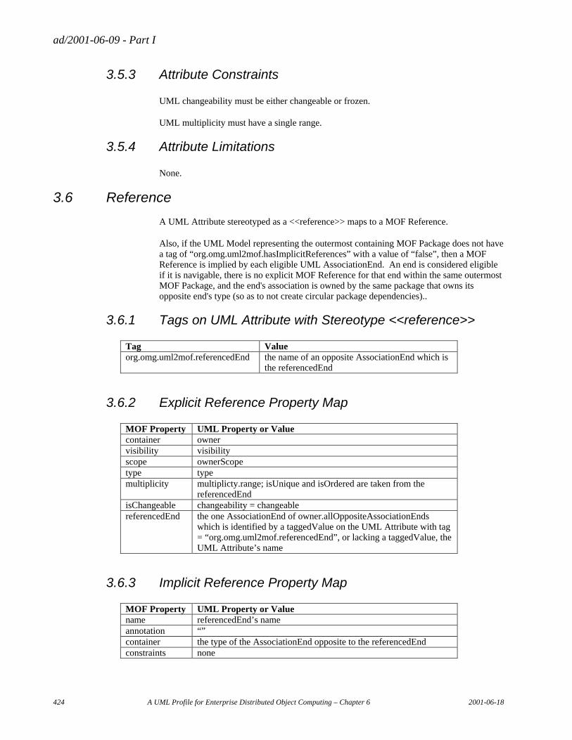
ad/2001-06-09 - Part I
424 A UML Profile for Enterprise Distributed Object Computing – Chapter 6 2001-06-18
3.5.3 Attribute Constraints
UML changeability must be either changeable or frozen.
UML multiplicity must have a single range.
3.5.4 Attribute Limitations
None.
3.6 Reference
A UML Attribute stereotyped as a <<reference>> maps to a MOF Reference.
Also, if the UML Model representing the outermost containing MOF Package does not have a tag of “org.omg.uml2mof.hasImplicitReferences” with a value of “false”, then a MOF Reference is implied by each eligible UML AssociationEnd. An end is considered eligible if it is navigable, there is no explicit MOF Reference for that end within the same outermost MOF Package, and the end's association is owned by the same package that owns its opposite end's type (so as to not create circular package dependencies)..
3.6.1 Tags on UML Attribute with Stereotype <<reference>>
Tag Value org.omg.uml2mof.referencedEnd the name of an opposite AssociationEnd which is
the referencedEnd
3.6.2 Explicit Reference Property Map
MOF Property UML Property or Value container owner visibility visibility scope ownerScope type type multiplicity multiplicty.range; isUnique and isOrdered are taken from the
referencedEnd isChangeable changeability = changeable referencedEnd the one AssociationEnd of owner.allOppositeAssociationEnds
which is identified by a taggedValue on the UML Attribute with tag = “org.omg.uml2mof.referencedEnd”, or lacking a taggedValue, the UML Attribute’s name
3.6.3 Implicit Reference Property Map
MOF Property UML Property or Value name referencedEnd’s name annotation “” container the type of the AssociationEnd opposite to the referencedEnd constraints none
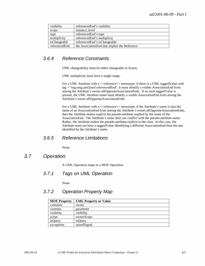
ad/2001-06-09 - Part I
2001-06-18 A UML Profile for Enterprise Distributed Object Computing – Chapter 6 425
visibility referencedEnd’s visibility scope instance_level type referencedEnd’s type multiplicity referencedEnd’s multiplicty isChangeable referencedEnd’s isChangeable referencedEnd the AssociationEnd that implies the Reference
3.6.4 Reference Constraints
UML changeability must be either changeable or frozen.
UML multiplicity must have a single range.
For a UML Attribute with a <<reference>> stereotype, if there is a UML taggedValue with tag = “org.omg.uml2mof.referencedEnd”, it must identify a visible AssociationEnd from among the Attribute’s owner.allOppositeAssociationEnds. If no such taggedValue is present, the UML Attribute name must identify a visible AssociationEnd from among the Attribute’s owner.allOppositeAssociationEnds.
For a UML Attribute with a <<reference>> stereotype, if the Attribute’s name is also the name of an AssociationEnd from among the Attribute’s owner.allOppositeAssociationEnds, then the Attribute makes explicit the pseudo-attribute implied by the name of the AssociationEnd. The Attribute’s name does not conflict with the pseudo-attribute name. Rather, the Attribute makes the pseudo-attribute explicit in the class. In this case, the Attribute must not have a taggedValue identifying a different AssociationEnd than the one identified by the Attribute’s name.
3.6.5 Reference Limitations
None.
3.7 Operation
A UML Operation maps to a MOF Operation.
3.7.1 Tags on UML Operation
None.
3.7.2 Operation Property Map
MOF Property UML Property or Value container owner contents parameter visibility visibility scope ownerScope isQuery isQuery exceptions raisedSignal
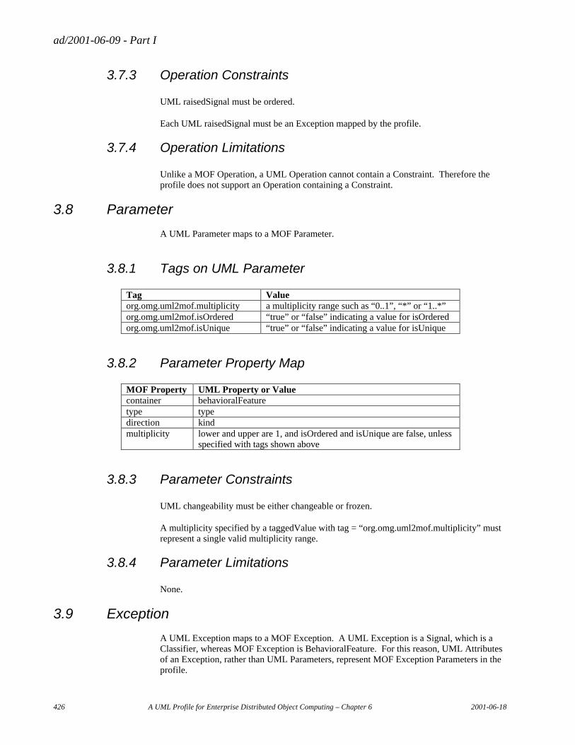
ad/2001-06-09 - Part I
426 A UML Profile for Enterprise Distributed Object Computing – Chapter 6 2001-06-18
3.7.3 Operation Constraints
UML raisedSignal must be ordered.
Each UML raisedSignal must be an Exception mapped by the profile.
3.7.4 Operation Limitations
Unlike a MOF Operation, a UML Operation cannot contain a Constraint. Therefore the profile does not support an Operation containing a Constraint.
3.8 Parameter
A UML Parameter maps to a MOF Parameter.
3.8.1 Tags on UML Parameter
Tag Value org.omg.uml2mof.multiplicity a multiplicity range such as “0..1”, “*” or “1..*” org.omg.uml2mof.isOrdered “true” or “false” indicating a value for isOrdered org.omg.uml2mof.isUnique “true” or “false” indicating a value for isUnique
3.8.2 Parameter Property Map
MOF Property UML Property or Value container behavioralFeature type type direction kind multiplicity lower and upper are 1, and isOrdered and isUnique are false, unless
specified with tags shown above
3.8.3 Parameter Constraints
UML changeability must be either changeable or frozen.
A multiplicity specified by a taggedValue with tag = “org.omg.uml2mof.multiplicity” must represent a single valid multiplicity range.
3.8.4 Parameter Limitations
None.
3.9 Exception
A UML Exception maps to a MOF Exception. A UML Exception is a Signal, which is a Classifier, whereas MOF Exception is BehavioralFeature. For this reason, UML Attributes of an Exception, rather than UML Parameters, represent MOF Exception Parameters in the profile.
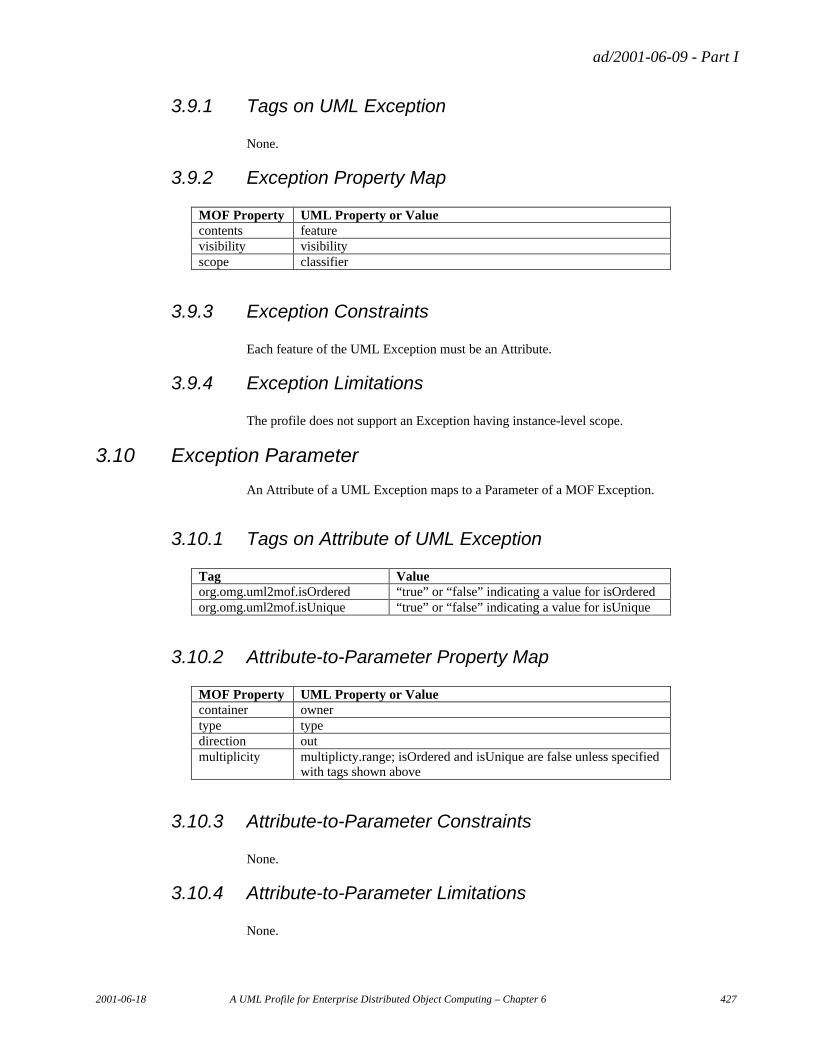
ad/2001-06-09 - Part I
2001-06-18 A UML Profile for Enterprise Distributed Object Computing – Chapter 6 427
3.9.1 Tags on UML Exception
None.
3.9.2 Exception Property Map
MOF Property UML Property or Value contents feature visibility visibility scope classifier
3.9.3 Exception Constraints
Each feature of the UML Exception must be an Attribute.
3.9.4 Exception Limitations
The profile does not support an Exception having instance-level scope.
3.10 Exception Parameter
An Attribute of a UML Exception maps to a Parameter of a MOF Exception.
3.10.1 Tags on Attribute of UML Exception
Tag Value org.omg.uml2mof.isOrdered “true” or “false” indicating a value for isOrdered org.omg.uml2mof.isUnique “true” or “false” indicating a value for isUnique
3.10.2 Attribute-to-Parameter Property Map
MOF Property UML Property or Value container owner type type direction out multiplicity multiplicty.range; isOrdered and isUnique are false unless specified
with tags shown above
3.10.3 Attribute-to-Parameter Constraints
None.
3.10.4 Attribute-to-Parameter Limitations
None.
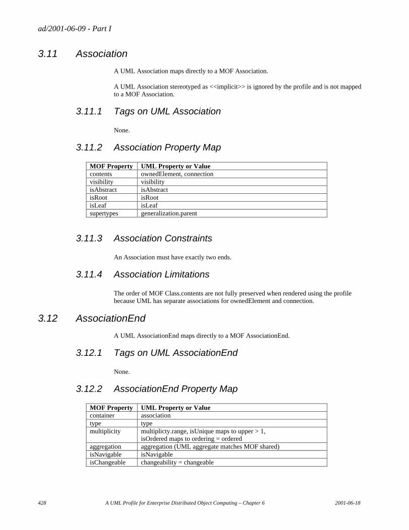
ad/2001-06-09 - Part I
428 A UML Profile for Enterprise Distributed Object Computing – Chapter 6 2001-06-18
3.11 Association
A UML Association maps directly to a MOF Association.
A UML Association stereotyped as <<implicit>> is ignored by the profile and is not mapped to a MOF Association.
3.11.1 Tags on UML Association
None.
3.11.2 Association Property Map
MOF Property UML Property or Value contents ownedElement, connection visibility visibility isAbstract isAbstract isRoot isRoot isLeaf isLeaf supertypes generalization.parent
3.11.3 Association Constraints
An Association must have exactly two ends.
3.11.4 Association Limitations
The order of MOF Class.contents are not fully preserved when rendered using the profile because UML has separate associations for ownedElement and connection.
3.12 AssociationEnd
A UML AssociationEnd maps directly to a MOF AssociationEnd.
3.12.1 Tags on UML AssociationEnd
None.
3.12.2 AssociationEnd Property Map
MOF Property UML Property or Value container association type type multiplicity multiplicty.range, isUnique maps to upper > 1,
isOrdered maps to ordering = ordered aggregation aggregation (UML aggregate matches MOF shared) isNavigable isNavigable isChangeable changeability = changeable
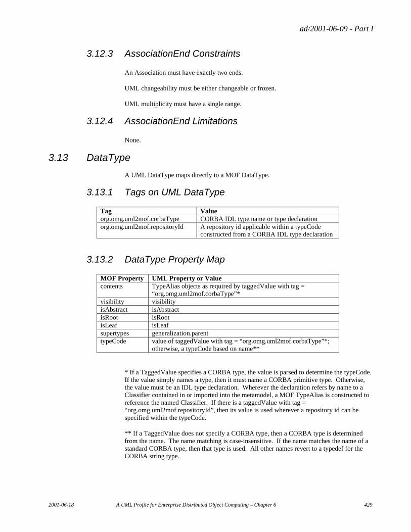
ad/2001-06-09 - Part I
2001-06-18 A UML Profile for Enterprise Distributed Object Computing – Chapter 6 429
3.12.3 AssociationEnd Constraints
An Association must have exactly two ends.
UML changeability must be either changeable or frozen.
UML multiplicity must have a single range.
3.12.4 AssociationEnd Limitations
None.
3.13 DataType
A UML DataType maps directly to a MOF DataType.
3.13.1 Tags on UML DataType
Tag Value org.omg.uml2mof.corbaType CORBA IDL type name or type declaration org.omg.uml2mof.repositoryId A repository id applicable within a typeCode
constructed from a CORBA IDL type declaration
3.13.2 DataType Property Map
MOF Property UML Property or Value contents TypeAlias objects as required by taggedValue with tag =
“org.omg.uml2mof.corbaType”* visibility visibility isAbstract isAbstract isRoot isRoot isLeaf isLeaf supertypes generalization.parent typeCode value of taggedValue with tag = “org.omg.uml2mof.corbaType”*;
otherwise, a typeCode based on name**
* If a TaggedValue specifies a CORBA type, the value is parsed to determine the typeCode. If the value simply names a type, then it must name a CORBA primitive type. Otherwise, the value must be an IDL type declaration. Wherever the declaration refers by name to a Classifier contained in or imported into the metamodel, a MOF TypeAlias is constructed to reference the named Classifier. If there is a taggedValue with tag = “org.omg.uml2mof.repositoryId”, then its value is used wherever a repository id can be specified within the typeCode.
** If a TaggedValue does not specify a CORBA type, then a CORBA type is determined from the name. The name matching is case-insensitive. If the name matches the name of a standard CORBA type, then that type is used. All other names revert to a typedef for the CORBA string type.
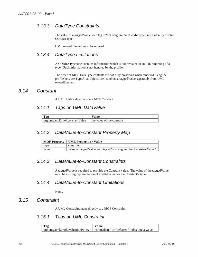
ad/2001-06-09 - Part I
430 A UML Profile for Enterprise Distributed Object Computing – Chapter 6 2001-06-18
3.13.3 DataType Constraints
The value of a taggedValue with tag = “org.omg.uml2mof.corbaType” must identify a valid CORBA type.
UML ownedElement must be ordered.
3.13.4 DataType Limitations
A CORBA typecode contains information which is not revealed in an IDL rendering of a type. Such information is not handled by the profile.
The order of MOF DataType.contents are not fully preserved when rendered using the profile because TypeAlias objects are listed via a taggedValue separately from UML ownedElement.
3.14 Constant
A UML DataValue maps to a MOF Constant.
3.14.1 Tags on UML DataValue
Tag Value org.omg.uml2mof.constantValue the value of the constant
3.14.2 DataValue-to-Constant Property Map
MOF Property UML Property or Value type classifier value value of taggedValue with tag = “org.omg.uml2mof.constantValue”
3.14.3 DataValue-to-Constant Constraints
A taggedValue is required to provide the Constant value. The value of the taggedValue must be a string representation of a valid value for the Constant’s type.
3.14.4 DataValue-to-Constant Limitations
None.
3.15 Constraint
A UML Constraint maps directly to a MOF Constraint.
3.15.1 Tags on UML Constraint
Tag Value org.omg.uml2mof.evaluationPolicy “immediate” or “deferred” indicating a value
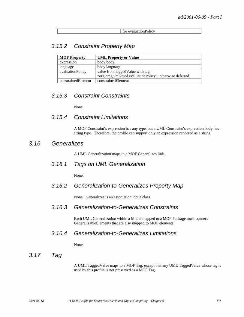
ad/2001-06-09 - Part I
2001-06-18 A UML Profile for Enterprise Distributed Object Computing – Chapter 6 431
for evaluationPolicy
3.15.2 Constraint Property Map
MOF Property UML Property or Value expression body.body language body.language evaluationPolicy value from taggedValue with tag =
“org.omg.uml2mof.evaluationPolicy”; otherwise deferred constrainedElement constrainedElement
3.15.3 Constraint Constraints
None.
3.15.4 Constraint Limitations
A MOF Constraint’s expression has any type, but a UML Constraint’s expression body has string type. Therefore, the profile can support only an expression rendered as a string.
3.16 Generalizes
A UML Generalization maps to a MOF Generalizes link.
3.16.1 Tags on UML Generalization
None.
3.16.2 Generalization-to-Generalizes Property Map
None. Generalizes is an association, not a class.
3.16.3 Generalization-to-Generalizes Constraints
Each UML Generalization within a Model mapped to a MOF Package must connect GeneralizableElements that are also mapped to MOF elements.
3.16.4 Generalization-to-Generalizes Limitations
None.
3.17 Tag
A UML TaggedValue maps to a MOF Tag, except that any UML TaggedValue whose tag is used by this profile is not preserved as a MOF Tag.
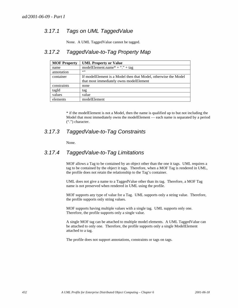
ad/2001-06-09 - Part I
432 A UML Profile for Enterprise Distributed Object Computing – Chapter 6 2001-06-18
3.17.1 Tags on UML TaggedValue
None. A UML TaggedValue cannot be tagged.
3.17.2 TaggedValue-to-Tag Property Map
MOF Property UML Property or Value name modelElement.name* + “.” + tag annotation “” container If modelElement is a Model then that Model, otherwise the Model
that most immediately owns modelElement constraints none tagId tag values value elements modelElement
* if the modelElement is not a Model, then the name is qualified up to but not including the Model that most immediately owns the modelElement — each name is separated by a period (“.”) character.
3.17.3 TaggedValue-to-Tag Constraints
None.
3.17.4 TaggedValue-to-Tag Limitations
MOF allows a Tag to be contained by an object other than the one it tags. UML requires a tag to be contained by the object it tags. Therefore, when a MOF Tag is rendered in UML, the profile does not retain the relationship to the Tag’s container.
UML does not give a name to a TaggedValue other than its tag. Therefore, a MOF Tag name is not preserved when rendered in UML using the profile.
MOF supports any type of value for a Tag. UML supports only a string value. Therefore, the profile supports only string values.
MOF supports having multiple values with a single tag. UML supports only one. Therefore, the profile supports only a single value.
A single MOF tag can be attached to multiple model elements. A UML TaggedValue can be attached to only one. Therefore, the profile supports only a single ModelElement attached to a tag.
The profile does not support annotations, constraints or tags on tags.
ad/2001-06-09 - Part I
2001-06-18 A UML Profile for Enterprise Distributed Object Computing – Chapter 6 433
4. Guidelines
This section gives guidelines for designing metamodels using the UML profile for MOF. These guidelines are drawn from several experiences of using UML to design and extend metamodels deployed using MOF.
Refer to the MOF Specification for a comprehensive explanation of MOF.
4.1 Modularity
Separate different modeling areas into different metamodels. Minimize dependencies between metamodels. Make no circular dependencies between them — otherwise valid CORBA IDL interfaces cannot be generated.
The outermost package of a deployed metamodel can thought of as a type. It is the type of each MOF package extent defined by the metamodel. Avoid nesting metamodels as owned elements so that the metamodels can be deployed in various combinations rather than only as one enormous metamodel. A metamodel can import rather than own other metamodels. Importing gives the same organizational advantage as nesting without imposing strong composition. Metamodels can be imported in two ways: clustered and unclustered. If clustered, an imported metamodel is fully deployed within an extent of the importing metamodel, just as if the imported metamodel had been nested.
Use package inheritance to achieve polymorphism of package extents. If a MOF package inherits from a base package, then an extent of the package can be used wherever an extent of the base package can be used.
4.2 Associations
Give meaningful names to associations, even if you do not display the names in diagrams. The association name is used to define interfaces to access and manage links.
Generally, put an association in the same package as one of its connected classes. If the connected classes are in separate packages, put the association in the most specific package.
When extending an existing model from the outside, feel free to make associations to classes in the existing model. But use existing associations wherever they are appropriate. If you want to draw an association between specific classes for the purpose of showing an existing association between superclasses, then stereotype the association as <<implicit>> so that it is ignored in the mapping to MOF.
MOF does not support association classes or associations having more than two connections. In any case where you would use such an association, model the conceptual association as a class using separate associations for each connection.
ad/2001-06-09 - Part I
434 A UML Profile for Enterprise Distributed Object Computing – Chapter 6 2001-06-18
4.3 References
A MOF reference is like a derived attribute whose derivation is tied to an association. The values of a reference for an object are the objects linked to that object. Modifying reference values causes links to be added and/or deleted.
When designing a metamodel that extends another from the outside, define references only in the extending metamodel, not in the metamodel it extends.
The definition of a MOF reference affects how package extents contain links. In general, an association link and the objects it connects can all belong to different package extents. However, the MOF Specification defines the Reference Closure Rule which requires any link tied to a reference to be contained by the same package extent as the object having the reference. If an association has references on both ends, both linked objects and the link must all be contained in the same package extent. Before defining a reference, give thought to the Reference Closure Rule so that you do not mistakenly prevent links from interrelating objects across different package extents. Conversely, use a reference where you want to force links to be in the same package extent as the linked objects.
Here is an example. Suppose a metamodel has a class called GE and an association from GE to GE called Generalizes. One end is called supertype and the other is called subtype. Both ends are navigable. If a reference is on both ends, then a link can only connect GE objects within the same package extent. If a reference is only on the subtype end (referring to supertype) then a link must be in the same package extent as its subtype, but it can link to a supertype in the same or a different package extent.
4.4 DataTypes
Avoid defining a complex data type where a class can be used.
Avoid defining enumerations because they limit extensibility. There is no way to extend an enumeration type from an outside metamodel.
4.5 Names
Form multiword names by concatenating words with no intervening spaces, hyphens or underscores. For names of packages, classifiers, and associations upcase the first letter of each word. For names of features and association ends upcase the first letter of each word except for the first word in the name. Do not prefix all of the names in a package with the package name — the package name is already part of the fully qualified name.
Using spaces, punctuation or leading numerals in names can cause problems for middleware, programming language, and XML bindings.
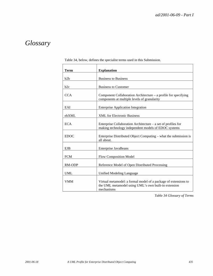
ad/2001-06-09 - Part I
2001-06-18 A UML Profile for Enterprise Distributed Object Computing 435
Glossary
Table 34, below, defines the specialist terms used in this Submission.
Term Explanation
b2b Business to Business
b2c Business to Customer
CCA Component Collaboration Architecture – a profile for specifying components at multiple levels of granularity
EAI Enterprise Application Integration
ebXML XML for Electronic Business
ECA Enterprise Collaboration Architecture – a set of profiles for making technology independent models of EDOC systems
EDOC Enterprise Distributed Object Computing – what the submission is all about.
EJB Enterprise JavaBeans
FCM Flow Composition Model
RM-ODP Reference Model of Open Distributed Processing
UML Unified Modeling Language
VMM Virtual metamodel: a formal model of a package of extensions to the UML metamodel using UML’s own built-in extension mechanisms
Table 34 Glossary of Terms

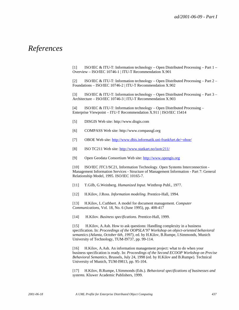
ad/2001-06-09 - Part I
2001-06-18 A UML Profile for Enterprise Distributed Object Computing 437
References
[1] ISO/IEC & ITU-T: Information technology – Open Distributed Processing – Part 1 – Overview – ISO/IEC 10746-1 | ITU-T Recommendation X.901
[2] ISO/IEC & ITU-T: Information technology – Open Distributed Processing – Part 2 – Foundations – ISO/IEC 10746-2 | ITU-T Recommendation X.902
[3] ISO/IEC & ITU-T: Information technology – Open Distributed Processing – Part 3 – Architecture – ISO/IEC 10746-3 | ITU-T Recommendation X.903
[4] ISO/IEC & ITU-T: Information technology – Open Distributed Processing – Enterprise Viewpoint – ITU-T Recommendation X.911 | ISO/IEC 15414
[5] DISGIS Web site: http://www.disgis.com
[6] COMPASS Web site: http://www.compassgl.org
[7] OBOE Web site: http://www.dbis.informatik.uni-frankfurt.de/~oboe/
[8] ISO TC211 Web site: http://www.statkart.no/isotc211/
[9] Open Geodata Consortium Web site: http://www.opengis.org
[10] ISO/IEC JTC1/SC21, Information Technology. Open Systems Interconnection - Management Information Services - Structure of Management Information - Part 7: General Relationship Model, 1995. ISO/IEC 10165-7.
[11] T.Gilb, G.Weinberg. Humanized Input. Winthrop Publ., 1977.
[12] H.Kilov, J.Ross. Information modeling. Prentice-Hall, 1994.
[13] H.Kilov, L.Cuthbert. A model for document management. Computer Communications, Vol. 18, No. 6 (June 1995), pp. 408-417
[14] H.Kilov. Business specifications. Prentice-Hall, 1999.
[15] H.Kilov, A.Ash. How to ask questions: Handling complexity in a business specification. In: Proceedings of the OOPSLA’97 Workshop on object-oriented behavioral semantics (Atlanta, October 6th, 1997), ed. by H.Kilov, B.Rumpe, I.Simmonds, Munich University of Technology, TUM-I9737, pp. 99-114.
[16] H.Kilov, A.Ash. An information management project: what to do when your business specification is ready. In: Proceedings of the Second ECOOP Workshop on Precise Behavioral Semantics, Brussels, July 24, 1998 (ed. by H.Kilov and B.Rumpe). Technical University of Munich, TUM-I9813, pp. 95-104.
[17] H.Kilov, B.Rumpe, I.Simmonds (Eds.). Behavioral specifications of businesses and systems. Kluwer Academic Publishers, 1999.
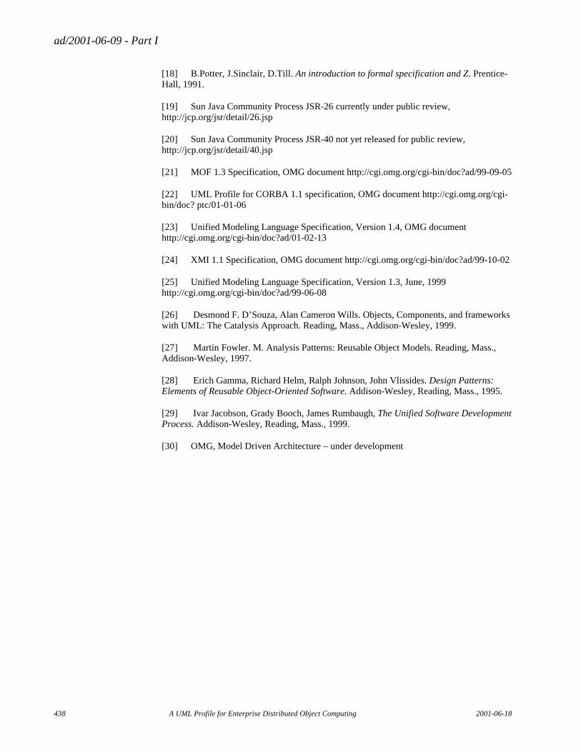
ad/2001-06-09 - Part I
438 A UML Profile for Enterprise Distributed Object Computing 2001-06-18
[18] B.Potter, J.Sinclair, D.Till. An introduction to formal specification and Z. Prentice-Hall, 1991.
[19] Sun Java Community Process JSR-26 currently under public review, http://jcp.org/jsr/detail/26.jsp
[20] Sun Java Community Process JSR-40 not yet released for public review, http://jcp.org/jsr/detail/40.jsp
[21] MOF 1.3 Specification, OMG document http://cgi.omg.org/cgi-bin/doc?ad/99-09-05
[22] UML Profile for CORBA 1.1 specification, OMG document http://cgi.omg.org/cgi-bin/doc? ptc/01-01-06
[23] Unified Modeling Language Specification, Version 1.4, OMG document http://cgi.omg.org/cgi-bin/doc?ad/01-02-13
[24] XMI 1.1 Specification, OMG document http://cgi.omg.org/cgi-bin/doc?ad/99-10-02
[25] Unified Modeling Language Specification, Version 1.3, June, 1999 http://cgi.omg.org/cgi-bin/doc?ad/99-06-08
[26] Desmond F. D’Souza, Alan Cameron Wills. Objects, Components, and frameworks with UML: The Catalysis Approach. Reading, Mass., Addison-Wesley, 1999.
[27] Martin Fowler. M. Analysis Patterns: Reusable Object Models. Reading, Mass., Addison-Wesley, 1997.
[28] Erich Gamma, Richard Helm, Ralph Johnson, John Vlissides. Design Patterns: Elements of Reusable Object-Oriented Software. Addison-Wesley, Reading, Mass., 1995.
[29] Ivar Jacobson, Grady Booch, James Rumbaugh, The Unified Software Development Process. Addison-Wesley, Reading, Mass., 1999.
[30] OMG, Model Driven Architecture – under development

ad/2001-06-09 - Part I
2001-06-18 A UML Profile for Enterprise Distributed Object Computing 439
Recommended