188 | P a g e
A STUDY COMPARISON OF DROP PANELS
UNDER INFLUENCE OF PUNCHING SHEAR
USING ANSYS.16.0
Yogesh A.Chaudhari1, Prof.G.B.Katti
2
1PG Student,
2Professor, Department of Civil Engineering,
Late G. N. Sapkal College of Engineering, Nasik (India)
ABSTRACT
The connections between the floor slab and column in a flat slab structure are generally the most critical part as
far as the strength is concerned because it is a region where large moments and shear forces are concentrated.
In this paper FEA model of slab column connection is model using ANSYS 16.0.Punching shear effect is
compared with circular and rectangular drop panel. Results are plotted in graphical form. Total deformation,
normal stress, Shear stress and Von-misses stresses are compared in this paper
Keywords— ANSYS, Drop Panel, Flat Slab, Punching
I. INTRODUCTION
Common practice of design and construction is to support the slabs by beams and support the beams by
columns. This may be called as beam-slab construction. The beams reduce the available net clear ceiling height.
Hence in warehouses, offices and public halls sometimes beams are avoided and slabs are directly supported by
columns. These types of construction are aesthetically appealing also. These slabs which are directly supported
by columns are called Flat Slabs. Punching shear failure is a major problem encountered in the design of
reinforced concrete flat plates. Flat plate slabs are economical since they have no beams and hence can reduce
the floor height by 10-15%. Further the formwork is simpler and structure is elegant. Hence flat plate slab
construction has been in practice in the west for a long time. However, the technology has seen large-scale use
only in the last decade and is one of the rapidly developing technologies in the Indian building industry today.
Material advances in concrete quality available for construction, improvement in quality of construction; easier
design and numerical techniques has contributed to the rapid growth of the technology in India It is widely
known that the slab-column connection is a critical component in the slab-column frame system as shown in
Figure 1.1. This is the region of slab immediately adjacent to the column that has to transmit large torsion, shear
and bending moments between slab and column and is therefore susceptible to punching shear failure.
.
II. SYSTEM DEVELOPMENT
ANSYS 16 is useful to finite element simulation for RCC structure use Solid 186 for concrete, link8 for Rebar
(Reinforcement), Conta 174 and Targe 173 to define contact between them.
SOLID186 Element Description
189 | P a g e
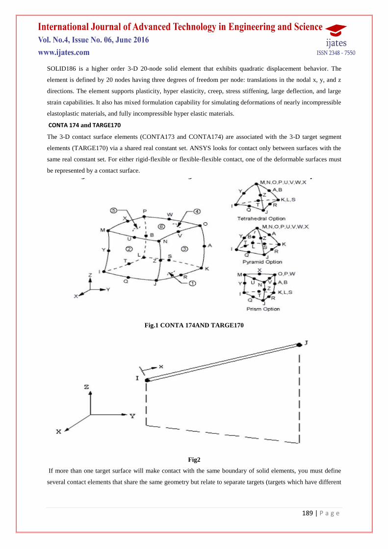
SOLID186 is a higher order 3-D 20-node solid element that exhibits quadratic displacement behavior. The
element is defined by 20 nodes having three degrees of freedom per node: translations in the nodal x, y, and z
directions. The element supports plasticity, hyper elasticity, creep, stress stiffening, large deflection, and large
strain capabilities. It also has mixed formulation capability for simulating deformations of nearly incompressible
elastoplastic materials, and fully incompressible hyper elastic materials.
CONTA 174 and TARGE170
The 3-D contact surface elements (CONTA173 and CONTA174) are associated with the 3-D target segment
elements (TARGE170) via a shared real constant set. ANSYS looks for contact only between surfaces with the
same real constant set. For either rigid-flexible or flexible-flexible contact, one of the deformable surfaces must
be represented by a contact surface.
Fig.1 CONTA 174AND TARGE170
Fig2
If more than one target surface will make contact with the same boundary of solid elements, you must define
several contact elements that share the same geometry but relate to separate targets (targets which have different
190 | P a g e
real constant numbers), or you must combine two target surfaces into one (targets that share the same real
constant numbers).
Fig.3 Modeling and analysis
III. PROBLEM STATEMENT
The Finite Element Model consisted of square flat plates 1200 mm length and 140 mm thick with 160 mm
square reinforced concrete column stubs extending 160 mm above the plate. All the slabs were identical in
dimensions. The reinforcement was distributed uniformly throughout the width of the slab as shown in model.
IV. MODELLING AND ANALYSIS
The Finite Element Model consisted of square and circular flat plates 1200 mm length and 140 mm thick with
160 mm square reinforced concrete column stubs extending 160 mm above the plate. All the slabs were
identical in dimensions. The reinforcement was distributed uniformly throughout the width of the slab as shown
in model.
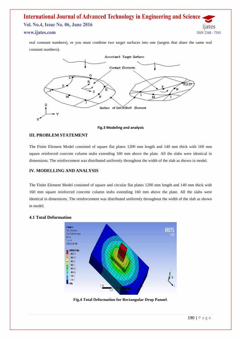
4.1 Total Deformation
Fig.4 Total Deformation for Rectangular Drop Pannel.

191 | P a g e
Fig.5 Total Deformation for Circular Drop Pannel
Fig.6 Load Vs Deformation
4.2 Shear Stress
Fig.7 Shear Stress for Rectangular Drop Pannel
192 | P a g e
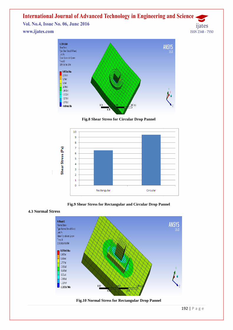
Fig.8 Shear Stress for Circular Drop Pannel
Fig.9 Shear Stress for Rectangular and Circular Drop Pannel
4.3 Normal Stress
Fig.10 Normal Stress for Rectangular Drop Pannel

193 | P a g e
Fig.11 Normal Stress for Circular Drop Pannel
Fig.12 Normal Stress for Rectangular and Circular Drop Pannel
4.4 Equivalent Stress
Fig.13 Equivalent Stress for Rectangular Drop Pannel
194 | P a g e
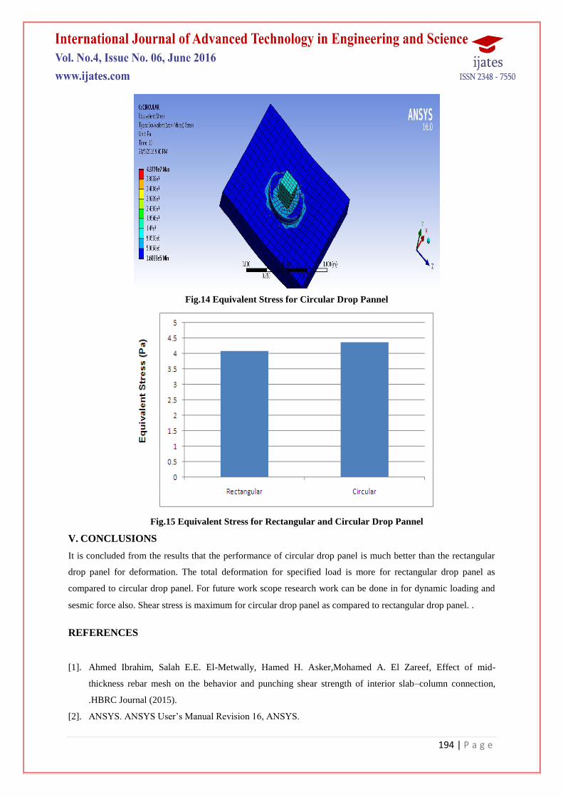
Fig.14 Equivalent Stress for Circular Drop Pannel
Fig.15 Equivalent Stress for Rectangular and Circular Drop Pannel
V. CONCLUSIONS
It is concluded from the results that the performance of circular drop panel is much better than the rectangular
drop panel for deformation. The total deformation for specified load is more for rectangular drop panel as
compared to circular drop panel. For future work scope research work can be done in for dynamic loading and
sesmic force also. Shear stress is maximum for circular drop panel as compared to rectangular drop panel. .
REFERENCES
[1]. Ahmed Ibrahim, Salah E.E. El-Metwally, Hamed H. Asker,Mohamed A. El Zareef, Effect of mid-
thickness rebar mesh on the behavior and punching shear strength of interior slab–column connection,
.HBRC Journal (2015).
[2]. ANSYS. ANSYS User’s Manual Revision 16, ANSYS.
195 | P a g e
[3]. IS 1893-Part 1. Indian Standard Criteria for Earthquake Resistant Design of Structures, Bureau of Indian
Standards, New Delhi, India, 2002.
[4]. IS 456. Indian Standard Plain and Reinforced Concrete Code of Practice, Bureau of Indian Standards, New
Delhi, India, 2000.
[5]. M. Priya, S. Greeshma and K. N. Suganya (2015), Finite Element Analysis of Slab - Column Joint Under
Lateral Loading .Asian Journal of Civil Engineering (BHRC) vol. 16, no. 2 (2015)
Recommended