Centre for Research in Earth & Space Science (CRESS)York Alumni Astronaut Steve MacLean’s EVA, STS 115, Sep 13, 2006 (Photo: NASA/CSA)
A Small Balloon/Satellite Platform for Space Science Research
Yunlong Lin
with his team at
York University

Centre for Research in Earth & Space Science (CRESS)
Outline
1 Research Area and ExperienceYES Program, EDSat, QuickSat …Spectrum of Small Satellites
2 Concurrent Engineering3 40s Small Balloon/Satellite Platform:
40kg, 40Watts, 40Km, 40days 4 Key technologies development for Space Science
Missions5 Space Science Package and scientific Applications6 Summary
Centre for Research in Earth & Space Science (CRESS)
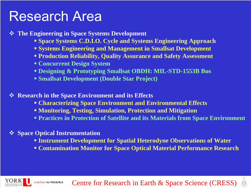
Research Area The Engineering in Space Systems Development
Space Systems C.D.I.O. Cycle and Systems Engineering ApproachSystems Engineering and Management in Smallsat DevelopmentProduction Reliability, Quality Assurance and Safety AssessmentConcurrent Design SystemDesigning & Prototyping Smallsat OBDH: MIL-STD-1553B BusSmallsat Development (Double Star Project)
Research in the Space Environment and its EffectsCharacterizing Space Environment and Environmental EffectsMonitoring, Testing, Simulation, Protection and MitigationPractices in Protection of Satellite and its Materials from Space Environment
Space Optical InstrumentationInstrument Development for Spatial Heterodyne Observations of Water Contamination Monitor for Space Optical Material Performance Research
Centre for Research in Earth & Space Science (CRESS)
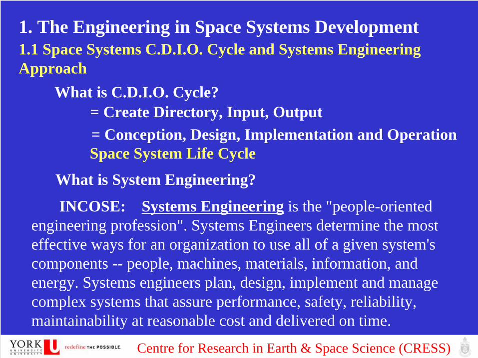
1. The Engineering in Space Systems Development1.1 Space Systems C.D.I.O. Cycle and Systems Engineering Approach
What is C.D.I.O. Cycle?= Create Directory, Input, Output= Conception, Design, Implementation and Operation
What is System Engineering?
INCOSE: Systems Engineering is the "people-oriented engineering profession". Systems Engineers determine the most effective ways for an organization to use all of a given system's components -- people, machines, materials, information, and energy. Systems engineers plan, design, implement and manage complex systems that assure performance, safety, reliability, maintainability at reasonable cost and delivered on time.
Space System Life Cycle

Centre for Research in Earth & Space Science (CRESS)
Systems Engineering Approach: Top Down modelSystems Engineering is concerned with the effective design,
production, deployment, operation, maintenance, refinement, and retirement of reliable systems within cost and time constraints.
Systems Engineering applies an appropriate combination of theories and tools, carried out through the use of a suitable methodology and a set of system management procedures, to address real world problems that are often of large scale and scope.
Systems engineering activities vary from requirements definition or specification to the conceptual and functional development of systems.
Systems engineer takes a "top down" perspective dealing with details only as needed to guarantee successful implementation. Whereas the product engineer deals with system internals, the systems engineer also addresses the external view of the system through the system's interface to other systems, users, and managers.

Centre for Research in Earth & Space Science (CRESS)
INCOSE
The Vee Model - The Vee Model addresses the technical aspect of the project cycle and represents the sequence of project events.
The left side of the Vee [is] a representation of the evolution of user requirements into parts and lines of code through the process of decomposition and definition.
The right side of the Vee represents the integration and verification of the system components into successive levels of assembly. (Forsberg, 1992, 1995)

Centre for Research in Earth & Space Science (CRESS)
Applying SE in SE (Systems Engineering in Space Engineering):Top Down modelling of ISO/IEC 15288, Manage the Processes to
become more efficient and cost-effectiveGoal: To create an understanding of the complete environment and
dependencies. To define interactions between processes and activities.Output: a dynamic model of ISO 15288 down to activity level,
including inputs, outputs and methods, long term tools, personnel and controls. Applying ISO 9001: 2000 (1998) Quality Management Certification System in Space Engineering:- Principle: Customer focus- Leadership - Involvement of people - Processes approach - System approach to management - Continual improvement - Factual approach to decision making- Mutually beneficial supplier relationships
Centre for Research in Earth & Space Science (CRESS)
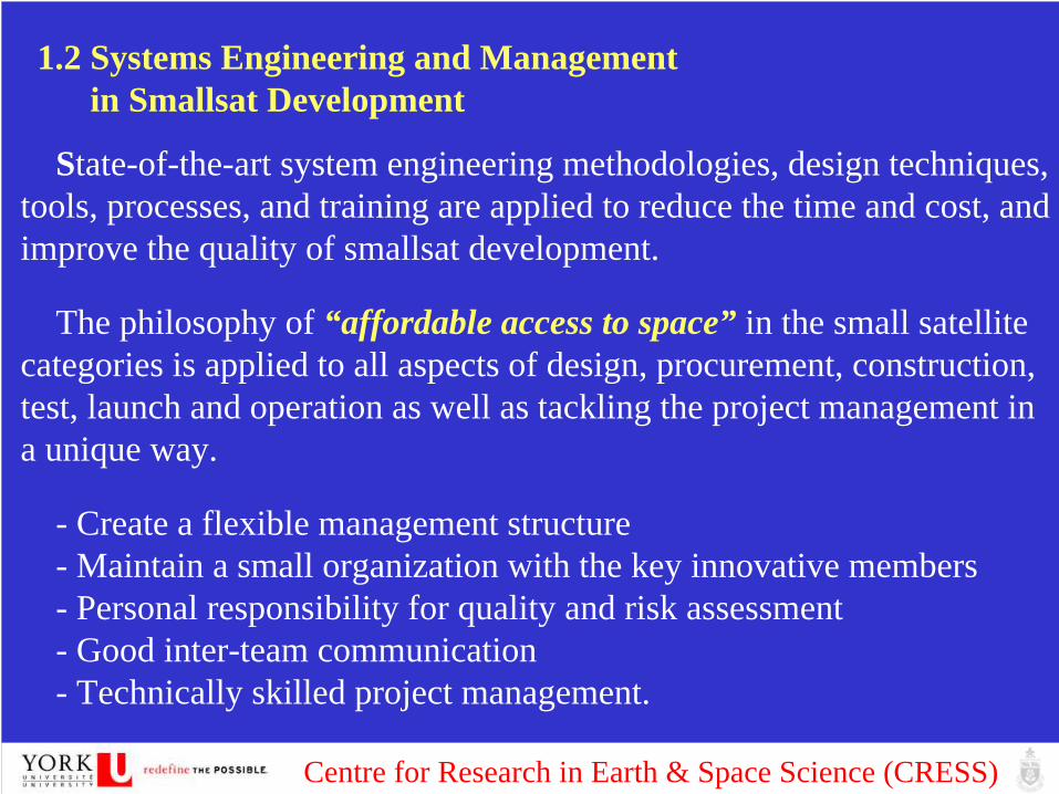
1.2 Systems Engineering and Management in Smallsat Development
State-of-the-art system engineering methodologies, design techniques, tools, processes, and training are applied to reduce the time and cost, and improve the quality of smallsat development.
The philosophy of “affordable access to space” in the small satellite categories is applied to all aspects of design, procurement, construction, test, launch and operation as well as tackling the project management in a unique way.
- Create a flexible management structure - Maintain a small organization with the key innovative members- Personal responsibility for quality and risk assessment- Good inter-team communication- Technically skilled project management.

Centre for Research in Earth & Space Science (CRESS)
- A vertically integrated system were setup, thus not to have to rely totally on sub-contractors while also being able to maintain a close watch on quality. - Implement International Organization for Standardization (ISO)’s
aerospace total quality management systems (ISO9000/AS9100 family). - A ‘one vote’ Production Assurance (PA) Manager take an overseeing
responsibility to ensure a PA plan is followed. - Space standard, norms and database are applied in all the phases of
simulation, integration and test. - On the technical side, driven by design-to-cost-and-schedule, apply
COTS components by means of layered redundancy and systematic hardening in smallsat engineering. - All the new technologies are flight-tested.- The interface standards (mechanical, electrical and data systems) - Modularity on smallsat platform.

Centre for Research in Earth & Space Science (CRESS)
1.3 Production Reliability, Quality Assurance and Safety Assessment
Multi-disciplinary methods, tools, and processes including modeling and simulation will be used to define the smallsat architecture to improve performance, risk management, safety, reliability, testability, quality, efficiency and flexibility of application.
1.4 Concurrent Design System
Concurrent Design System is one of most effective practices and methodologies to enable actual smallsat engineering. It is an Integration Design Environment (IDE) opened to multi-disciplinary designers and users for interdisciplinary and inter-directorate applications, based on Concurrent Engineering Methodology.

Centre for Research in Earth & Space Science (CRESS)
The facility contains extensive simulation and computing resources with industry standard software and hardware for the application of the integrated design tools, project data, mission and system models. CDS can execute all the smallsat sub-system level and system level designs and simulations, based on integration of high-end software tools.
The team orientated design system allows simultaneous participation of all mission domains including Programmatics/AIV, operations, cost assessment, risk analysis, CAD and simulation. The design system is a “collaborative, co-operative, collective” system that can support all perspectives in parallel throughout the product life cycle, and is an essential tool for mission evaluation, decision-making and risk management.

Centre for Research in Earth & Space Science (CRESS)
Concurrent Engineering for Space Mission Development and Spacecraft Design and Implementation

Centre for Research in Earth & Space Science (CRESS)
Sample: PCW Mission ConceptOrbit: Molniya and Tundra orbits

Centre for Research in Earth & Space Science (CRESS)
Orbit Selected: Molniya CSA Recommended

Centre for Research in Earth & Space Science (CRESS)
S/C Design Requirement: I: Power Requirements: Power
Budget
Potential Payload Average Power
(W)
Communications 500
Meteorological Primary 180
Auxiliary 45
Total Payload Power 725
Total Power Requirement 941.25
Total Power Requirement with
80% Contingency
1694.25
Centre for Research in Earth & Space Science (CRESS)
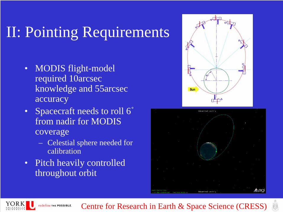
II: Pointing Requirements
• MODIS flight-model required 10arcsec knowledge and 55arcsec accuracy
• Spacecraft needs to roll 6˚ from nadir for MODIS
coverage– Celestial sphere needed for
calibration• Pitch heavily controlled
throughout orbit

Centre for Research in Earth & Space Science (CRESS)
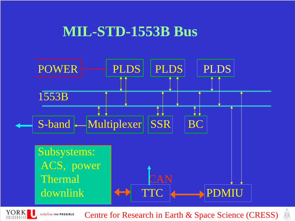
III On-board Data Management• MIL 1553
– Serial data bus– Data Link layer and Physical Layers– Dual redundancy– Linear bus
• CAN bus– Same as above– Signal is encoded using NRZ – Linear Bus
• Wireless bus– Bluetooth
Centre for Research in Earth & Space Science (CRESS)
POWER PLDS PLDS PLDS
1553B
S-band Multiplexer SSR BC
Subsystems:ACS, powerThermal CANdownlink TTC PDMIU
MIL-STD-1553B Bus

Centre for Research in Earth & Space Science (CRESS)
Ionization and Space Hardening
• TID - Total Dose from all particles
• SEE - Single energetic particle effects device
• Displacement Damage –In semiconductors due to scattering interactions of incident particles such protons, neutrons

Centre for Research in Earth & Space Science (CRESS)
Fault Toleration - Redundancy• Error correcting memory
– parity bits – check for corruption.– SEE can effect RAM even when not accessed use scrubber
circuit• Physical Redundancy
– Three microprocessor boards – Compare their answers, voting logic real time fail-safe
• Watchdog timer – Perform a hard reset of a system unless a cetain sequence is
performed– Write to WDT at regular intervals, failure to do so will mean an
incorrect process and the system will restart.

Centre for Research in Earth & Space Science (CRESS)
MIL STD 1553B Data Management System (CSSAR, 1999) Standardization of On-Board S-band High Speed Data Management
Centre for Research in Earth & Space Science (CRESS)
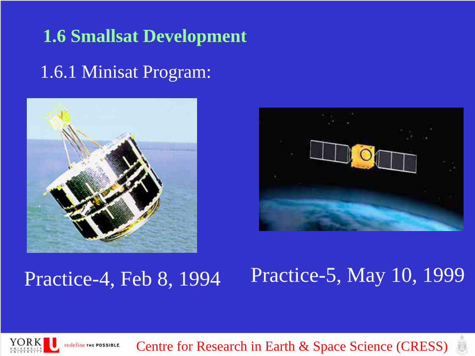
1.6 Smallsat Development
1.6.1 Minisat Program:
Practice-4, Feb 8, 1994 Practice-5, May 10, 1999
Centre for Research in Earth & Space Science (CRESS)
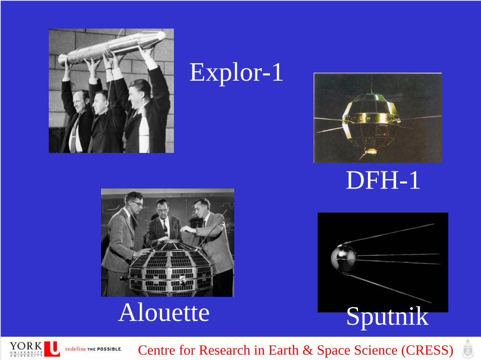
DFH-1
Alouette
Explor-1
Sputnik

Centre for Research in Earth & Space Science (CRESS)
Beijing-1(2004)SSTL, 78Kg
Qinghua-1 (2000)SSTL, 50Kg
Space Debris Probe, 80Kg

Centre for Research in Earth & Space Science (CRESS)
40s Platform for Lunar MicroRover Exploration(Orbitor)
UoSat 12, Lunar exploration

Centre for Research in Earth & Space Science (CRESS)
Centre for Research in Earth & Space Science (CRESS)
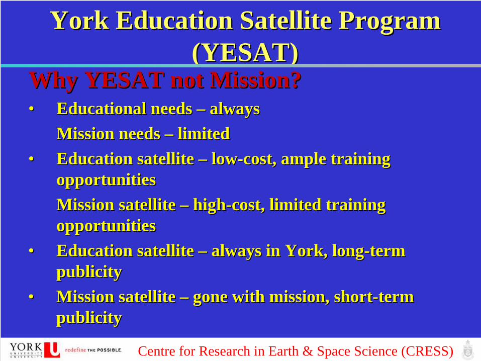
York Education Satellite Program York Education Satellite Program (YESAT)(YESAT)
Why YESAT not Mission?Why YESAT not Mission?•• Educational needs Educational needs –– alwaysalways
Mission needs Mission needs –– limitedlimited•• Education satellite Education satellite –– lowlow--cost, ample training cost, ample training
opportunitiesopportunitiesMission satellite Mission satellite –– highhigh--cost, limited training cost, limited training opportunitiesopportunities
•• Education satellite Education satellite –– always in York, longalways in York, long--term term publicitypublicity
•• Mission satellite Mission satellite –– gone with mission, shortgone with mission, short--term term publicitypublicity

Centre for Research in Earth & Space Science (CRESS)
YES ProgramYES Program
Starting in 2003 Starting in 2003 ……•• NanoSat NanoSat and Swarms Designand Swarms Design
•• MicroSat MicroSat and and ConstellationConstellation•• MiniSatMiniSat

Centre for Research in Earth & Space Science (CRESS)
Satellite Bus YES-1 YES-2
Mass(Kg) 50-120 200-300
Payloads bearing capacity 50% 40% - 60%
Layout Cube or Central cylinder with rigid substrate panel
Orbit sun synchronous orbits, near circular orbit and LEO
sun synchronous orbits at altitude of 500 to 1000Km
Attitude control mode 3 axis stabilization 3 axis stabilization or spin axis stabilization
Attitude knowledge accuracy 0.3 to 0.01 degree (3 sigma) <0.03 degree (3 sigma)
Pointing accuracy 0.6-0.1degree <0.1 degree
Attitude stability 0.05-0.005 degree/second <0.0005 degree/second
Attitude and Orbit control offset momentum wheel plusmagnetic control with orbitmaneuver and maintenancecapability
mainly offset momentum wheel plus magnetic control,or reaction wheel plus magnetic control with orbital maneuver and maintenance
On-board Data handling CAN bus technique andPackaging Telemetry system
CAN bus techniqueOr 1553B bus or others
TTC USB with GPS orbitdetermination as supplementary
USB with GPS orbitdetermination as supplementary
Data Storage 4Gbits 8Gbits
Data Downlink S band, 2Mbps S band or X band, 4Mbps
Solar array output 200W 800W
In-Space Propulsion Chemical Thrusters Hydrazine(N2 H4 ) or cold gaspropulsion system with orbitmaneuver and maintenanceCapability *Electrical Engine is next step

Centre for Research in Earth & Space Science (CRESS)
York Education Satellite Program York Education Satellite Program (YESAT)(YESAT)
Why YESAT not Mission?Why YESAT not Mission?•• Educational needs Educational needs –– alwaysalways
Mission needs Mission needs –– limitedlimited•• Education satellite Education satellite –– lowlow--cost, ample training cost, ample training
opportunitiesopportunitiesMission satellite Mission satellite –– highhigh--cost, limited training cost, limited training opportunitiesopportunities
•• Education satellite Education satellite –– always in York, longalways in York, long--term term publicitypublicity
•• Mission satellite Mission satellite –– gone with mission, shortgone with mission, short--term term publicitypublicity
Centre for Research in Earth & Space Science (CRESS)
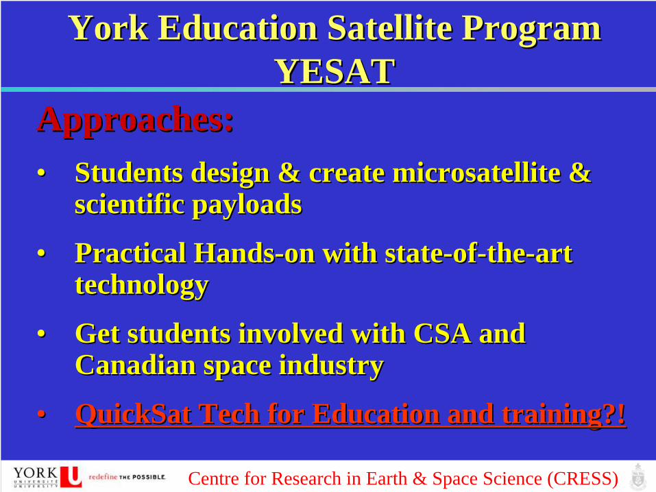
York Education Satellite Program York Education Satellite Program YESATYESAT
Approaches:Approaches:•• Students design & create microsatellite & Students design & create microsatellite &
scientific payloadsscientific payloads
•• Practical HandsPractical Hands--on with stateon with state--ofof--thethe--art art technologytechnology
•• Get students involved with CSA and Get students involved with CSA and Canadian space industryCanadian space industry
•• QuickSat Tech for Education and training?!QuickSat Tech for Education and training?!

Centre for Research in Earth & Space Science (CRESS)
York Education Satellite Program York Education Satellite Program YESAT Road MapYESAT Road Map
YESAT YESAT ActivitiesActivities
CRESSCRESSSpace Engineering LabSpace Engineering Lab
YESATYESATMicrosatellitesMicrosatellites
YESATYESATMission AnalysisMission Analysis
Guidance, Navigation Guidance, Navigation and Controland Control
Design & Create Design & Create Scientific PayloadsScientific Payloads
GroundGroundTesting & ValidationTesting & Validation
YESATYESATGround StationGround Station

Centre for Research in Earth & Space Science (CRESS)
QuickSat (CSA) at York for QuickSat (CSA) at York for EducationEducation

Centre for Research in Earth & Space Science (CRESS)
QuickSat (CSA) at York for QuickSat (CSA) at York for EducationEducation

Centre for Research in Earth & Space Science (CRESS)
2. Research in the Space Environment and its Effects2.1 Characterizing Space Environment and its EffectsSpace System:Atmospheric DragMicrogravityVacuumTemperatureSolar UVAtomic OxygenRadiation
Charging and DischargingTotal Ionize DoseSingle Event Effect
Outgas and Contamination

Centre for Research in Earth & Space Science (CRESS)
Space Radiation
- Cosmic Ray- Solar Flare- Coronal Mass Ejection

Centre for Research in Earth & Space Science (CRESS)
Trapped Charge Particles and Radiation Belt
e
p

Centre for Research in Earth & Space Science (CRESS)
SEE in Avionics
Atmospheric nuetrons
-Launch system -Aircraft

Centre for Research in Earth & Space Science (CRESS)
2.2 Monitoring, Simulation, Testing, Protection and Mitigation
Monitoring- Science Mission- Space Environment Monitoring (SEM)
System on board application satellite:Remote Sensing SatelliteWeather Satellite

Centre for Research in Earth & Space Science (CRESS)
Centre for Research in Earth & Space Science (CRESS)
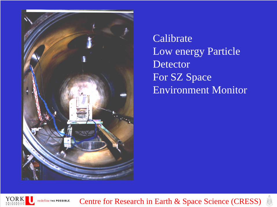
CalibrateLow energy Particle DetectorFor SZ Space Environment Monitor

Centre for Research in Earth & Space Science (CRESS)
Ground Testing
SEU

Centre for Research in Earth & Space Science (CRESS)

Centre for Research in Earth & Space Science (CRESS)

Centre for Research in Earth & Space Science (CRESS)
SEE Protect Methods
- Shielding Material®
- Two CPU redundancy
- Reed-Solomon coding Correction
- Software Self-correction
- Smart controller against SEL

Centre for Research in Earth & Space Science (CRESS)
252Cf for SEE test

Centre for Research in Earth & Space Science (CRESS)
More than 1000 ICs have been tested.Among them: PC104, Electronics Stack used in NASALaser communication guidance system

Centre for Research in Earth & Space Science (CRESS)

Centre for Research in Earth & Space Science (CRESS)

Centre for Research in Earth & Space Science (CRESS)
The 6300A emission arises from de-excitation
Excitation by secondary electronsThermal excitation by heated electronsDissociated recombination of ionsCascading from
The 5577A emission arises from atomic Oxygen
The 5200A emission arises from atomic Nitrogen )5200()()(
)5577()()(
)6300()()5577()()(
)()()3()()3(
)6300()()(
42
11
311
1**2
1
1
31
AhSNDN
AhSODO
AhPOAhDOSO
DOOeODOePODOePO
AhPODO
ν
ν
νν
ν
+→
+→
+→+→
+→+
→+
→+
+→
++2O
)(1SO
Aurora and night glow - 6300A aurora an ISIS-II spacecraft Experiment
Canada’s space observation on aurora and airglowISISFreja (Uv, red line photonometer, rocket observations )WindiiE-POP

Centre for Research in Earth & Space Science (CRESS)
Sub-storm over north China (Killing electrons)

Centre for Research in Earth & Space Science (CRESS)
THEMIS:
Centre for Research in Earth & Space Science (CRESS)
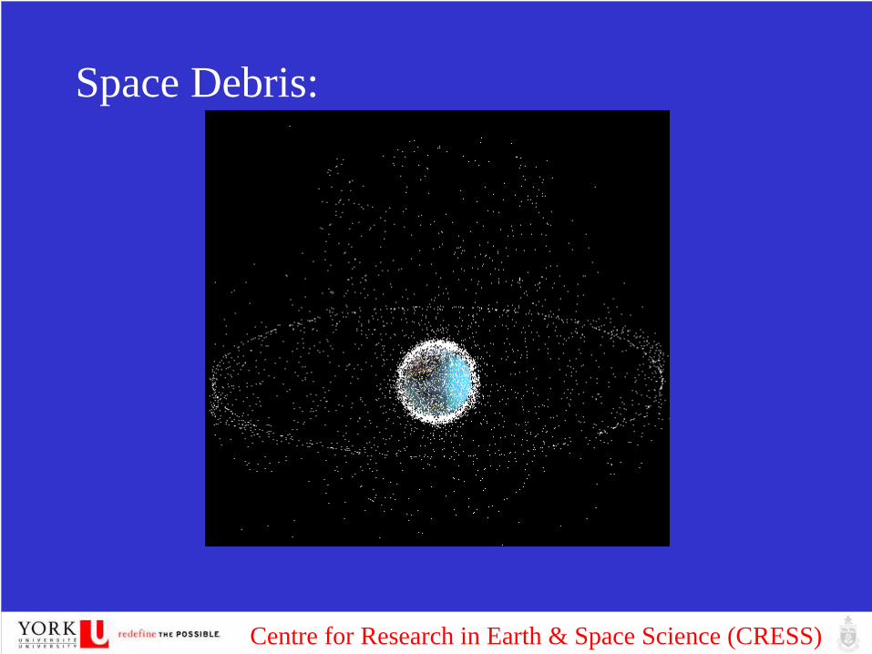
Space Debris:

Centre for Research in Earth & Space Science (CRESS)

Centre for Research in Earth & Space Science (CRESS)
Smart-1’s impact dust
CFHT

Centre for Research in Earth & Space Science (CRESS)
Space Golf (Element 21 Golf Company in Toronto):3g with tiny GPS receiver
Battery: 5 daysScaling up for the futureFree-flying testAtmospheric clean-up

Centre for Research in Earth & Space Science (CRESS)
3 Space Optical Instrumentation3.1 Instrument Development for Spatial Heterodyne Observations of Water
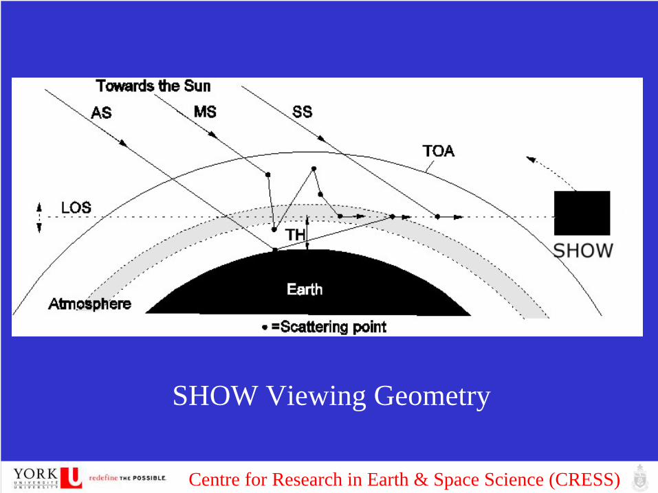
The Spatial Heterodyne Observation of Water (SHOW) project, a new instrument was developed to measure water vapour from 15km to 85km height, through observing water absorption of the solar scattering light from the atmosphere, in limb configuration, on a global scale, using the unique capabilities provided by Spatial Heterodyne Spectroscopy (SHS).
Centre for Research in Earth & Space Science (CRESS)
SHOW Viewing Geometry

Centre for Research in Earth & Space Science (CRESS)
Prediction of SHOW water vapor observation through the revised LIMBTRAN model

Centre for Research in Earth & Space Science (CRESS)
In the general case of a polychromatic source, the intensity I(x) in the fringe localization plane can be written as a function of the spatial dimension x in the dispersion plane:
An interference filter is used to reject out of band wavelengths that would result in aliased fringes and/or a non-unique recovery of the incident spectrum.
σθσσπσ dxBxI LLo]})tan()(4(2cos[1){()( 0−+= ∫
∞
θL
L1
L2
L3
Imaging detector
Inputaperture
Incidentwave front
Exitingwave fronts
2γ
θL
Grating
Grating
PrismsField-widened spatial heterodyne spectrometers can be achieved using fixed field-widening prisms. Field- widening enhanced the light collecting power for SHS.

Centre for Research in Earth & Space Science (CRESS)
Brassboard Components and its Alignment

Centre for Research in Earth & Space Science (CRESS)
4 Space Science Package (SSP)Payloads and Data Management
- UV/VIS/NIR spectrometer- Aurora Imager- Space Weather Package (compact virtual Package)
Coordination and conjunction of other observationsOther satellitesBalloon observations (at 30-40km)UAV (at 10-12km)Ground observations

Centre for Research in Earth & Space Science (CRESS)
Spacecraft Design and Mission Development andGreen House Gases Monitoring from SpaceMicrotechnology ApplicationIn the early 90’s, the advent of the concept of small-sized/microsatellite design provided
an alternative approach to significantly decrease costs and enable commercialisation. This breakthrough utilizes alternate spacecraft design methodologies such as scale reduction, repacking/light weighting, microtechnology, high and/or low-level integration and functional design. The keen interest in microtechnology centres mainly on the structuring of macroscopic materials at the micrometer level.
Satellite OrbitAltitude (km) 600 Circular velocity (km/s) 7,558 orbit Angular velocity (deg/min) 3,723 Escape Velocity (km/s) 10,688 delta V Req. to deorbit (m/s) -156.7Sun-Synchronous Inclination (deg) 97.79 Revolutions per day 14.85 Period (min) 96.69 Max Eclipse(MIN) 35.49

Centre for Research in Earth & Space Science (CRESS)
The current York spacecraft requirements derived by the payload have led to a three-axis stabilized platform design using only reaction/momentum wheels and magnetorques. The spacecraft design employs components that are to both standard and non-standard. This means that some of the components are readily available on the market while others are currently being space qualified. Radiation shielding of the spacecraft is only applied to the sensitive parts and shall be sufficient to tolerate a 600 km Sun Synchronous Orbit (SSO) for at least 4 years. The spacecraft presented in here is about 55Kg in mass and 60x50x40 cm in volume and 35% of the volume is taken up by the payloads.

Centre for Research in Earth & Space Science (CRESS)
Developing Bluetooth Wireless bus with UTIAS
• Reducing mass and volume of the bus wiring harness• Higher data transmission rates• Standardization –use of mature technology and COTS to
reduce cost, increase reliability, and decrease development time in the long run.
• Reliability: fault toleration and support for harsh environment of space, launch vibration tolerance
• Plug and play feature, easy removal and addition of nodes• Low maintenance• Optimally leading to schematic design and driver
development
Centre for Research in Earth & Space Science (CRESS)
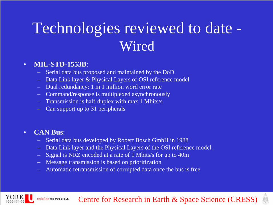
Technologies reviewed to date - Wired
• MIL-STD-1553B: – Serial data bus proposed and maintained by the DoD– Data Link layer & Physical Layers of OSI reference model– Dual redundancy: 1 in 1 million word error rate– Command/response is multiplexed asynchronously – Transmission is half-duplex with max 1 Mbits/s– Can support up to 31 peripherals
• CAN Bus:– Serial data bus developed by Robert Bosch GmbH in 1988– Data Link layer and the Physical Layers of the OSI reference model. – Signal is NRZ encoded at a rate of 1 Mbits/s for up to 40m– Message transmission is based on prioritization– Automatic retransmission of corrupted data once the bus is free

Centre for Research in Earth & Space Science (CRESS)
Technologies reviewed to date - Wired
• I2C: – Multimaster Serial data bus– Data rate upto 3.4Mbits/s.(Max length of bus 3 meters).– Does not provide means for error detection
• Ethernet:– Requires a host controller and has a bus topology– Transfer rates upto 1Gbits/s for fast Ethernet.– Used for long range high-bandwidth data transmission: equipment is costly and
configuration needed – Can use TCP/IP and UDP protocols. – No power output
Centre for Research in Earth & Space Science (CRESS)
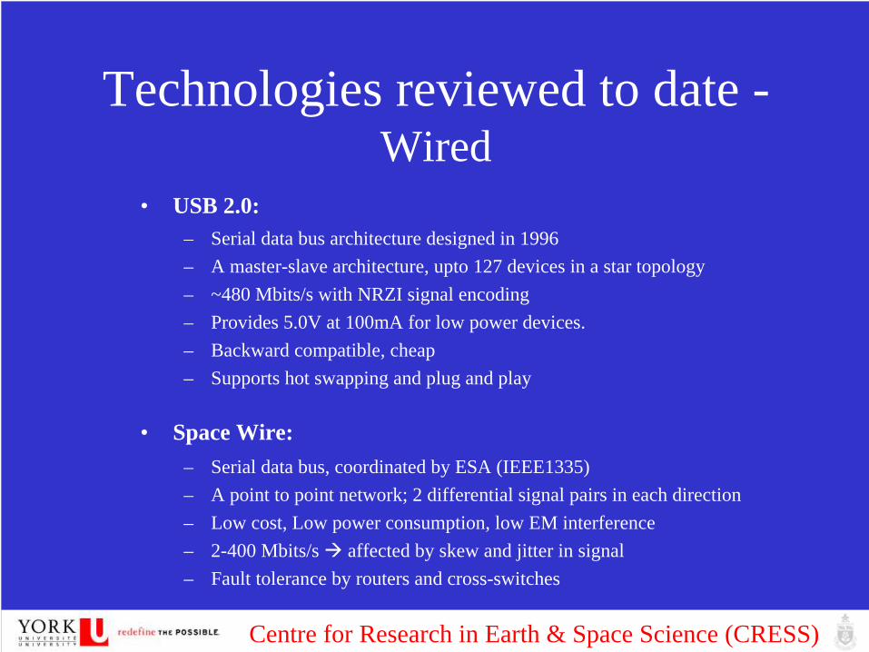
Technologies reviewed to date - Wired
• USB 2.0:– Serial data bus architecture designed in 1996– A master-slave architecture, upto 127 devices in a star topology– ~480 Mbits/s with NRZI signal encoding– Provides 5.0V at 100mA for low power devices. – Backward compatible, cheap– Supports hot swapping and plug and play
• Space Wire:– Serial data bus, coordinated by ESA (IEEE1335) – A point to point network; 2 differential signal pairs in each direction– Low cost, Low power consumption, low EM interference – 2-400 Mbits/s affected by skew and jitter in signal– Fault tolerance by routers and cross-switches

Centre for Research in Earth & Space Science (CRESS)
Technologies reviewed to date - Wired
• FireWire 800 (IEEE1394b): – Serial data bus developed by Apple.– Supports multiple hosts per bus– Requires non-cyclic bus topology. – Data rates of ~786 Mbits/s with better CPU utilization than USB.– Supports upto 63 devices, – Can bridge buses to provide up to 1024 buses with 63 devices each. – Provide up to 45W of power at 30V (no load-unregulated).– Easy to add new devices, – Features PnP and hot swapping, making the reconfiguration of topology and
troubleshooting very simple. – Two supported modes of data transfer.
• Asynchronous mode: obtains a receiver acknowledgement and guarantees data transfer• Isochronous mode: guarantees on time data transfer (bandwidth and latency) real time.
Stops receiver from overflowing in case of continuous data.

Centre for Research in Earth & Space Science (CRESS)
Technologies reviewed to date - Wireless
• WiFi:– IEEE802.11g,n,y– Serial Data transfer, with mesh topology – Depending on type of WLAN uses 2.4,5 or 3.7GHzwith max throughput on g
being 54 Mbits/s.– Security: effective radius of ~35m encryption, address specific access– Increased power consumption (400mA TX and ~40mA standby)– PnP and hot swappable
• Zigbee – IEEE802.15.4– PHYS & MAC of DLL in OSI model– High level communication Protocol– Operates in 2.4 GHz, 915\868 MHz RF bands– Low data transfer rates(250 kbits/s, 40kbits/s, 20kbits/s)– Lower power (30mA TX, small standby)– Security –address specific access, data encryption, frame integrity

Centre for Research in Earth & Space Science (CRESS)
Technologies reviewed to date - Wireless
• Bluetooth– IEEE 802.15, A WPAN protocol– Operation at 2.402-2.480GHz with Frequency Hopping at 1600/s– Uses GFSK (Gaussian Frequency Shift Key)– Master-multi slave piconet– Connection:
– Query to find devices– Paging (Active mode, Sniff mode, Hold mode, Park Mode)
Class 1 Class 2 Class 3~100m ~10 m ~10cm20dB 4dB 0dB

Centre for Research in Earth & Space Science (CRESS)
Preliminary Analysis Results
• Optimum wired solution: Firewire– Low Power, power output, high speed, plug and
play, fault toleration can be implemented• Optimum wireless solution: Bluetooth
– Low power, reduce harnessing (mass and volume), high speed, plug and play, secure, radiation tolerant (FHSS)

Centre for Research in Earth & Space Science (CRESS)
40s Platform with ARMS
Adapter and Releaser for Multiple Satellites

Centre for Research in Earth & Space Science (CRESS)

Centre for Research in Earth & Space Science (CRESS)

Centre for Research in Earth & Space Science (CRESS)

Centre for Research in Earth & Space Science (CRESS)

Centre for Research in Earth & Space Science (CRESS)环月卫星六侧视图

Centre for Research in Earth & Space Science (CRESS)
Balloon Platform with Continuum Aerospace
Continuum Aerospacefloat altitudefloat durationday-night cycleslaunch/recovery locationsweather impact of above
York- Missions of short-term and long term interest- Instrumentation & its corresponding requirements- Student flights- satellite components qualification flights- Initial technology readiness demonstration flights

Centre for Research in Earth & Space Science (CRESS)
Instruments GRAS LIMA
Mass 2Kg (including all antenna) 7Kg
Size NAMURU II board: 11cm x 18cm x 3cmNadir antenna array: 20cm x 20cm x 4cm
Zenith antenna :9cm in diameter, 3cm high
12cm x 12cm x 15cm
Installation Requirements
Two antenna should be installed on either package wall or balloon surface, in Nadir and Zenith direction, respectively
Each of four channels needs to have its own light tight tube. The baffles would fit in the front 3cm of each tube (although this may be extended a bit).
PointingRequirements
Two antenna point to Nadir and Zenith direction within 1 degree, respectively
Four input apertures point to roughly 90 degree away from sunlight.More accuracy pointing may be obtained using additional pointing mirror.
Max. Power 10W 16 W
Data Rate 8 ~15Kbps 315Kbps
9Kg 26WTotal Data andData Rate
Total Data (for 10 days): 285Gbits in Max. Two 16GB USB flash memories are available for on-board data storage.
Data rate: 330Kbps in Max.Mobile Broadband Service from Stratos is available for downlink rate at 32, 64, 128 Kbps,
respectively. The Latitude coverage is below 780N. Kiruna is at 670N. There will be about 1 day and 2 days communication available in the mission beginning and the end, respectively. Roughly 10% of total data could be transmitted to ground during the flight.

Centre for Research in Earth & Space Science (CRESS)
2. The requirements to the Flight PackageThe requirements derived by the instrument (GPS Receiver for
Atmospheric Studies -GRAS, Limb IMaging of Aerosols - LIMA) have led to a request of a stabilized platform design.
The flight package design employs components that are to both standard and non-standard. This means that some of the
components are readily available on the market while others are currently being flight qualified against temperature, humidity and pressure variations, Electromagnetic interference, shocks
and drops. The flight package presented in here is about 20Kg in mass and 40cm x 40cm x 40 cm in volume and 45% of the mass (9Kg out
of 20Kg) is taken up by the instruments.

Centre for Research in Earth & Space Science (CRESS)
Subsystems Mass Power Size
Instruments 9 Kg 26W See Instrument Table.
Structure 4 Kg - 40cm x 40cm x 40cm
Thermal 0.5 Kg 1W -
Power 1.5 Kg 1W power unit with four batteries:8cm x 10cm x 3cmBody mount solar Array (face to sunlight):38cm x 38cm
On-Board Data Handling
2.5 Kg 4 W 35cm x 30cm
Attitude and Flight Path Determination (GPS)
- - -
Communication 2.5 Kg 5 W Terminal card:8 cm x 8 cm x 2cmAntenna:Diameter 13cm, thickness 5cm
Total 20 Kg 37W( peak)30W(a verage )40W(i nput)
Engineering Descriptions of the Flight Package

Centre for Research in Earth & Space Science (CRESS)
Mission: 150lb. to 40k ft.

Centre for Research in Earth & Space Science (CRESS)
Recommended


![Space-quality data from balloon-borne telescopes: the High … · 2012-05-15 · arXiv:1205.2957v1 [astro-ph.IM] 14 May 2012 Space-quality data from balloon-borne telescopes: the](https://img.pdfslide.us/doc/110x75/5f02cbe77e708231d4060dfe/space-quality-data-from-balloon-borne-telescopes-the-high-2012-05-15-arxiv12052957v1.jpg)