IJSRST151314| Received: 11 August 2015 | Accepted: 05 November 2015 | September-October 2015 [(1)4: 299-306]
© 2015 IJSRST | Volume 1 | Issue 4 | Print ISSN: 2395-6011 | Online ISSN: 2395-602X Themed Section: Science and Technology
299
A Novel 110KV Fault Current Limiter for Improving The Reliability of A
Substation Kadir Ahmed Dafedar
1 , Waseem Ahmed Halwegar
2
Dept of E&E, Anjuman institute of technology & Management, Bhatkal (Karnataka), India
ABSTRACT
In this paper, superconducting fault current limiter (FCL) is used as a novel technology for reducing the high
fault currents and enhancing the security of 110kV substation. The model of 110kV substation is developed
using the Matlab simulation program. The model is used to study at normal condition and short circuit analysis
with the Matlab software. In the model of the FCL its major components, operation control algorithm, sequence of
events and fault detection techniques are developed. The reduction of the fault currents are studied at the buses of
suspected high fault currents by installing the FCL. The waveform obtained is for with and without FCL and
comparison is done for the result. The transmission line is considered for the fault analysis using Fault Current
Limiter with and without. The simulation results obtained have demonstrated the effectiveness of FCL in
improving the system performance, reliability and security.
Keywords: Power system, substation, fault detection and system security, FCL, sequence activation algorithm,
transient model.
I. INTRODUCTION
When electric power systems are expanded and become
more interconnected, the fault current levels increase
beyond the capabilities of the existing equipment,
leaving circuit breakers and other substation components
in over-duty conditions. Fault current arises due to line
to line fault or line to ground fault (symmetrical or
asymmetrical fault) in the power system. This fault
results in sudden increase of current for small interval of
time. Circuit breakers, sometimes, cannot handle the
intense level of faults, so they fail to break the peak rest
of fault current and is enough to burn the insulation and
conductor. Handling these increasing fault currents often
requires the costly replacement of substation equipment
or the imposition of changes in the configuration by
splitting power system that may lead to decreased
operational flexibility and lower reliability.
To protect the electrical equipment the fault current
should be reduced and normalized. The circuit breaker
was before used to isolate the fault Section. If the fault
current is more than interruption capacity of circuit
breaker, it easily damages the electrical equipment in the
circuit. An alternative is to use Fault Current Limiters
(FCL) to reduce the fault current to a low acceptable
level. So that the existing switchgear still be used to
protect the power grid. So a new technology is adopted
to reduce the fault current and to enhance the security of
power system. This is the novel technique for reducing
high fault current using high temperature super
conducting fault current limiter (FCL). Now days the
generation system has became more complex and more
generation load is interconnected and control of fault
current is done by splitting the power system into zones.
The FCL has several advantages for a critical utility
problem with possible installation at interconnection,
transformer, bus-tie, feeder closing open point and large
industrial power point. A superconducting fault current
limiter (FCL) will be operating in a superconducting
state and is basically invisible to the power grid because
no major energy loss and voltage drop will be developed
across the device during normal operation. The FCL will
produce a certain value of impedance within a few
milliseconds due to the loss of superconductivity and
insert it into the circuit, thus reducing the fault currents
to levels that circuit breakers can handle.
International Journal of Scientific Research in Science and Technology (www.ijsrst.com)
300
Faults in power networks incur large short-circuit
currents flowing in the network and in some cases may
exceed the ratings of existing circuit breakers (CB) and
damage system equipment The problems of inadequate
CB short-circuit ratings have become more serious than
before since in many locations, the highest rating of the
CB available in the market has been used. To deal with
the problem, fault current limiters (FCLs) are often used
in the situations where insufficient fault current
interrupting capability exists [1].
Several types of FCL have been designed with different
superconducting materials. The resistive FCL is
preferable because it increases the decay speed of the
fault current by reducing the time constant of the decay
component of the fault currents, and can also make the
system less inductive. In 220kV/110kV/11kV the level
of fault current is very high and can exceed the
interruption capacity of the circuit breaker. The
feasibility of the FCL for reducing the fault current
levels, improving the system security and their impact
on changing the operation network topologies is used in
substation of and reduced the fault current to maximum
level[2]. The FCL is considered to be one of the
innovative devices of FACTS in electric power systems.
In this paper the modeling of 110 kV substations is
carried out using Matlab / Simulink software. Simulation
result obtained for fault currents at various lines likes
line1, line2, line3 with and without incorporating FCL
have been presented in this paper.
II. METHODS AND MATERIAL
A. Construction
FCL can generally be categorized into three broad types
[3]. They are Passive limiters, Solid state type limiters,
and Hybrid limiters. The FCL system in Fig. 1 [4]
consists of six FCL modules arranged in a cryostat with
suitable current leads and high voltage bushings and a
cryogenic supply. The dimensions of the cryostat are
approximately 2 m in diameter and about 5–6 meters in
length, which nearly fits into the field size of a 110 kV
substation. The FCL is designed and manufactured using
MCP-BSCCO-2212 monofilar components. The ceramic
tubular element (typically 50mm outer, 42mm inner
diameter, 370mm length) were produced by melt cast
processing and it is optimized to yield a material with
= 94k, = 10 A/mm2 and room temperature
resistivity = 5m ohm-cm. Where is critical
temperature and is current density. The final
component is obtained by soldering brass or copper
contact and a shunt of Cu-Ni alloy. These composites
are reinforced with FRP and machined into 2 to 3m long
monofilar coils. Two such coils are connected in series
with a brass or copper pipe coupled. A typical HTS
component has = 600A and during the fault, it is
subjected to a voltage of 150V. The cooling concept is
based on a refillable L storage and for a vacuum
pumps to control the nitrogen gas pressure and the
temperature inside the cryostat is 65k. One component
of the magnetic field triggered concept consists of a
MCP-BSCCO 2212 tube with suitable copper contacts at
both ends and a conventional coil that is wound directly
onto the tube. The bifilar coils shown in Fig. 1[5] are
made of MCP-BSCCO-2212 tube and have resistive
property, magnetic field triggered concept is used for
110kV FCL and in this concept the high electrical field
during limitation and very high rated current per HTS
elements. A group of FCL component are made into
modules shown in Fig.1 [5] of a certain rating and the
components are fixed between two round plates made of
epoxy-glass resin.
There is a small distance between the components to
keep the copper connection short to minimize the AC
losses in these connections. The component is made of
spiral shape to have compact design and maximum
electrical insulation length because the current is fed in
the outer radius and is fed out in the middle of the spiral.
An active length of each component is 40 cm and an
electrical field during limitation of 3.2 V/cm. The entire
assembly is placed in the cryostat with the nitrogen gas
filled to quench the arc with pressure of 5 bar inside.
The design value of the electrical field inside the
cryostat is 40kV/cm at 5 bar. The 110kV FCL have 93
component per modules and it rating is designed for
11.83 K and 1850 A. the length of 110kV FCL of
each component is 40 cms and electrical field during
limitation is 3.2 v/cms. When the quench in the
superconductor starts to develop the current commutates
into the conventional coil and the magnetic field of the
coil accelerates the quench. This function depends on
the strong magnetic field dependence of the
superconductor’s critical current.
International Journal of Scientific Research in Science and Technology (www.ijsrst.com)
301
There are four different type of breakdown mechanism
for high voltage FCL
L breakdown
breakdown
Surface flashover
Solid breakdown
The breakdown electrical field of at 1 bar and room
temperature is 24 kV/cm and that the free length from
high potential to ground for the 110kV voltage level at 1
bar is 1050mm. FCL is an innovative fault current
limiter. It works on the principle of Superconducting
Property. It is inactive under normal condition. It is in
active under fault condition, it inserts some resistance
into the line to limit the fault current. It suppresses the
fault current within first half cycle only. It operates
better than Circuit breakers, Relays, because the Circuit
breakers takes minimum 2-3 cycles before they getting
activated. The effect of SFCL on micro grid fault current
observed. The optimal place to SFCL is determined [6].
Figure 1. Construction of Fault Current Limiter
The assemble module of three phase 110 kV FCL as
shown in Fig. 2 [7].
Figure 2: Drawing and complete 3-phase- FLC 12-800
system
B. Simulation Model of FCL
The resistive type FCL is modeled considering four
fundamental parameters of a resistive type FCL. These
parameters and their selected values are [8]: 1)
Transition or response time = 2m.sec 2) Minimum
impedance = 0.01Ω. Maximum impedance = 20Ω 3)
Triggering current =550A 4) Recovery time = 10 msec.
The FCL working voltage is 139kV. The maximum
impedance value can be varied from 20 ohms to 27
ohms. The three phase FCL model developed in
Simulink/SimPower System is shown in Fig. 3 and the
single phase FCL model is developed to study single
line network [ 9]. The FCL model works as follows.
First, FCL model calculates the RMS value of the
passing current and then compares it with the
characteristic table. Second, if a passing current is larger
than the triggering current level, FCL resistance
increases to maximum impedance level in a predefined
response time. Finally, when the current level falls
below the triggering current level the system waits until
the recovery time and then goes into normal state. Fig. 3.
Simulink model of three phase FCL. The current
limiting resistance value is calculated and this value is
implemented in the simulation model. The important
parameter to be given in FCL is the current limiting
resistance value. The FCL model developed is tested in
both single phase and three phase test systems and the
current waveforms are recorded with the presence and
absence of FCL.
The simulation model of a three phase test system with
and without FCL and the current waveforms are
recorded. The fault current is induced in the source
directly in order to reduce the complexity of the
simulation model. The type of the fault induced in the
model is single phase to ground fault where it is induced
through the AC voltage source. An RMS block is needed
in order to calculate the RMS value of the incoming
current signal and to increase the impedance value
according to the limited fault current value specified in
the FCL characteristic table. The performance of the
FCL can also be tested in a power system generation and
distribution systems using three phases FCL for
controlling the fault current for each phase. Harmonics
filtration is used in order to reduce the harmonics caused
due to the abnormal fault current. A normal first order
filter is used for reducing the harmonics. The type of the
filter can be changed depending upon the application of
the system. A controlled voltage source is connected in
order to compensate the voltage sag caused due to the
induced fault current which is caused due to both
internal and external causes.

International Journal of Scientific Research in Science and Technology (www.ijsrst.com)
302
Figure 3: Simulink model of three phase FCL
C. Description of 110kv Substation
Single line diagram of 110kV substation is shown in Fig.
4. It consists of 110kV, 33kV, 66kV, 11kV transmission
lines and incoming lines are 110kV. It is having various
protection devices like circuit breaker and relays. The
protection of substation devices is very essential to have
good reliability of the power supply. The fault of
symmetrical and asymmetrical is protected by relays and
circuit breaker. During temporary or permanent fault,
the circuit breaker trip and isolate the faulty area. This
interrupt the supply and result in the loss of power to
consumer and the reliability also decreases. It also
affects the revenue of Power Corporation. If the fault is
temporary, it should be cleared very quickly without
isolating the consumer supply. The electrical equipments
that are installed in the substation need to be protected
from very large fault current.
The analysis and simulation is carried out with and
without FCL using Matlab in 110kV substation. In this
paper, an investigation has been carried out to limit the
fault current in the event of temporary fault by
installing FCL at suitable point in the substation.
The substation consists of four, 110kV transmission line
and the substation is a ring system. It is connected to
other substation so that in any occurrence of fault, power
supply can be taken from other 220/110kV substation. It
is automated and connected to 220kV substation through
SCADA. All the parameter, contingencies, load control
and maintenance schedule is obtained from local
dispatch centre (LDC).
The four, 110kV transmission line are,
Line1
Line2
Line3
Line4
The 110kV transmission line is feeding residential,
industrial, commercial and agricultural load. Often
temporary and permanent fault occurs leading to
interruption of power supply. During the temporary fault
the loss can be minimized by using the FCL in
switchyard. The fault current limiter should be
connected in series with the circuit breaker. During the
temporary fault the short circuit current is reduced to
normal range and the process moves uninterrupted.
There is no interruption of power supply, hence there is
increased of reliability in power system. In the
switchyard, the 110kV bus is feeding all the
transmission line (except incoming lines). The
transmission like is having protection device like
distance protection relay, phase differential relay,
circuit breaker(SF6), group operating system (GOS),
lightning arrestor, spark gap. But this is not enough to
protect the system from fault, so Fault Current Limiter
(FCL) should be installed to protect the electrical
equipment. Project model is made in Matlab, the four
110kV transmission line is considered. The Line1
110kV line is connected with Fault Current Limiter
(FCL) and it is placed in series with the circuit breaker.
The 110kV line of Line2 is connected to the load with
circuit breaker but no FCL and 110kV line1 is without
Fault Current Limiter and circuit breaker. All the 110kV
transmission line is disturbed with the three phase fault
and the simulation is observed with and without Fault
Current Limiter (FCL).
Figure 4: Single Line Diagram of 110 kV Substation

International Journal of Scientific Research in Science and Technology (www.ijsrst.com)
303
III. SIMULATION MODEL, RESULTS &
DISCUSSION
The Fig. 5 shown consists of three branch of 110kV
transmission line model in Matlab. The first, 110kV
line1 is shown with FCL installed. Secondly the 110kV
line2 is having circuit breaker in series with no FCL and
third 110kV transmission line3 does not have circuit
breaker or FCL connected to power system. The fault is
made to occur at all the three branches separately and
simulation is observed for all the branch.
Figure 5 : 110kV substation model in Matlab
Simulation of 110kV transmission line3
The 110kV transmission line1 is connected with Fault
Current Limiter (FCL) in series with the equipment. The
fault is made to occur for 0.1 sec at certain distance from
the switch yard and waveform is observed with and
without Fault Current Limiter (FCL). The Fig. 6 below
is the Matlab model of 110kV line1 with Fault Current
Limiter (FCL).
Figure 6 : Matlab model of 110kV line
Now Figure shown below are for asymmetrical fault
Waveform recorded with Fault Current Limiter
(FCL) connected to the transmission line and during
the fault of Phase A with Ground fault current
without FCL as shown in Fig. 7.
Figure 7 : Phase A to Ground Fault current without
FCL
Fig. 8 is the waveform of phase A to ground fault
current with FCL and it has reduce the fault current
to normal value.
Figure 8 : Waveform during fault of Phase A to
ground fault current with FCL
Phase B to Ground fault current is shown in Fig. 9
and FCL is not connected to the transmission line.
Figure 9 : Phase B to Ground fault current without
FCL
In Fig. 10 waveform is recorded for phase B to
ground fault current with FCL connected to
transmission line.
International Journal of Scientific Research in Science and Technology (www.ijsrst.com)
304
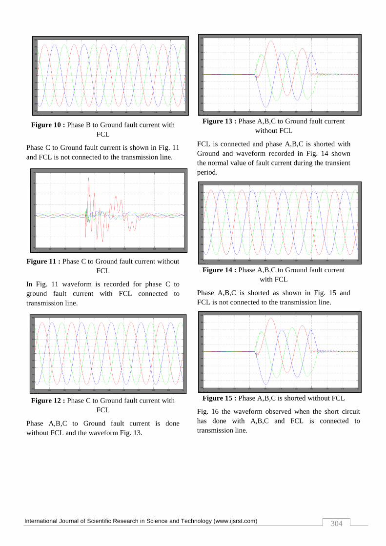
Figure 10 : Phase B to Ground fault current with
FCL
Phase C to Ground fault current is shown in Fig. 11
and FCL is not connected to the transmission line.
Figure 11 : Phase C to Ground fault current without
FCL
In Fig. 11 waveform is recorded for phase C to
ground fault current with FCL connected to
transmission line.
Figure 12 : Phase C to Ground fault current with
FCL
Phase A,B,C to Ground fault current is done
without FCL and the waveform Fig. 13.
Figure 13 : Phase A,B,C to Ground fault current
without FCL
FCL is connected and phase A,B,C is shorted with
Ground and waveform recorded in Fig. 14 shown
the normal value of fault current during the transient
period.
Figure 14 : Phase A,B,C to Ground fault current
with FCL
Phase A,B,C is shorted as shown in Fig. 15 and
FCL is not connected to the transmission line.
Figure 15 : Phase A,B,C is shorted without FCL
Fig. 16 the waveform observed when the short circuit
has done with A,B,C and FCL is connected to
transmission line.

International Journal of Scientific Research in Science and Technology (www.ijsrst.com)
305
Figure 16 : Phase A, B, C is shorted with FCL
installed
From the observation of the waveform, it is clear that the
fault occurs and the only protection is circuit breaker.
When FCL is connected to the transmission line, it
reduces the fault current to normal value and system is
protected from asymmetrical and symmetrical fault.
Hence this system protection is only for temporary fault
in the power system.
IV. CONCLUSION
This paper introduces the FCL as new technology for
reducing the short circuit currents at the 110kV level of
substation network. Therefore, the FCL improves the
system security with minimum short circuit currents.
Subsequently, improving the system reliability and
minimizing the loading on the feeders in steady state and
under contingency. The installation of FCL in the
substation removes the temporary fault. The device is
efficient in temporary fault and if permanent fault occurs
the FCL does not play any role. So the development
should be done to make FCL more operatable during
permanent fault. Hence FCL can be installed in any
substation to improve the reliability and to meet the
demand of the consumer effectively.
V. REFERENCES
[1] P. G. Slade, et al, "The Utility Requirements for A
Distribution Fault Current Limiters", IEEE
Transactions on Power Delivery, Vol. 7, No. 2
April 1992 507-515.
[2] M. S. El Moursi, and Roshdy Hegazy ―Novel
Technique for Reducing the High Fault Currents
and Enhancing the Security of ADWEA Power
System‖, IEEE Trans Power system, vol.28, no.1,
Feb 2013.
[3] V. Manish, ―Comprehensive overview, behavioral
model and simulation of a fault current limiter,‖
Master of Science in Electrical Engineering thesis,
Virginia Tech, Blacksburg, VA, 2009.
[4] Mathias Noe, Andrej Kudymow, Stefan Fink,
Steffen Elschner, Frank Breuer, Joachim Bock,
Heribert Walter, Martin Kleimaier, Karl-Heinz
Weck, Claus Neumann, Frank Merschel, Bernd
Heyder, Ulrich Schwing, Christian Frohne, Klaus
Schippl, and Mark Stemmle ―Conceptual Design
of a 110 kV Resistive Superconducting Fault
Current Limiter Using MCP-BSCCO 2212 Bulk
Material,‖ IEEE Transactions on Applied
Superconductivity, vol.17, no.2, June 2007.
[5] Naxan, Tenth EPRI Superconductivity Conference
Mathias Noearlsruher Institut für Technologie &
Joachim Bock, Achim Hobl, udith Schramm
Nexans SuperConductors GmbH EPRI 2011
October11-13, 2011.
[6] Study of position of SFCL for maximum fault
current limiter for power systems protection,
Sachin Trankatwar, Dr.S.L.Nalbalwar, Dr.
A.B.Nandgaonkar, International Journal of
Scientific & Engineering Research, Volume 4,
Issue 7, July-2013 866 ISSN 2229-5518.
[7] J.Bock, M. Bludau,R.Dommerque,A.Hobl, S.
Kraemer, M. O. Rikel, and S. Elschner, ―HTS
fault current limiters—First commercial devices
for distribution level grids in Europe,‖ IEEE
Trans. Appl. Supercond., vol. 21, no. 3, pp. 1202–
1205, Jun. 2011.
[8] Analysis of Positioning of Superconducting Fault
Current Limiter in Smart Grid Application S.
Srilatha , Dr.K.Venkata Reddy PG-Student,
Department of Electrical and Electronics
Engg.JNT University, Kakinada, India Assistant
Professor, Department of Electrical and
Electronics Engg, JNT University, Kakinada,
India, IJAIR.
[9] Kovalsky, L., Yuan, X., Tekletsadik, K., Keri, A.,
Bock, J. and Breuer, F., ‖Applications of
superconducting fault current limiters in electric
power transmission systems,‖ IEEE Trans. on
Applied Superconductivity, Vol. 15, No. 2, June
2005.
International Journal of Scientific Research in Science and Technology (www.ijsrst.com)
306
VI. AUTHOR’S DETAILS
1) Kadir Ahmed Dafedar
received B.E degree in
Electrical and Electronics
from Karnataka
University(KUD) Dharwad
in the year 2001 and M.Tech
in Power system from
Visvesvaraya Technological
University, Belgaum in the
year 2014.He has published several research papers in
the field of Electrical Engineering. Presently he is
working as Assistant Professor in Department of
Electrical & Electronics Engineering, Anjuman
institute of technology and management, Bhatkal
(Karnataka, INDIA). And his areas of interest are
Renewable energy sources and power system
protection.
2) Waseem Ahmed Halwegar
received B.E degree in Electrical
and Electronics from
Visvesvaraya Technological
University, Belgaum in the year
2010 and M.Tech in Digital
Electronics from Visvesvaraya
Technological University,
Belgaum in the year 2013.He
has published several research papers in the field of
Electrical Engineering. Presently he is working as
Assistant Professor in Department of Electrical &
Electronics Engineering, Anjuman institute of
technology and management, Bhatkal (Karnataka,
INDIA). And his areas of interest are Power
Electronics, Renewable energy sources and power
system protection.
Recommended