8/4/2019 A Noval Active Power Filter for Harmonic Supression
http://slidepdf.com/reader/full/a-noval-active-power-filter-for-harmonic-supression 1/12
Abstract
In this paper, a novel active power filter is proposed and implemented by sing a
voltage-source power converter with a
series connected inductor and capacitor
set. The power converter is controlled togenerate a compensating voltage that is
converted into a compensating current
via the series connected inductor andcapacitor set. The compensating current
flows into the power feeder in order to
suppress the harmonic currents
generated by nonlinear loads. The salient
advantages of the proposed active
Power filter are lower voltage rating of dc capacitor and power switchingdevices, smaller filter inductor, smaller
dimension, light weight, better filter
performance and low electromagneticinterference (EMI). A three-phase 100 k
VA active power filter is developed to
demonstrate the performance of the proposed method. The results show that
the proposed active power filter has the
expected performance.
8/4/2019 A Noval Active Power Filter for Harmonic Supression
http://slidepdf.com/reader/full/a-noval-active-power-filter-for-harmonic-supression 2/12
I. INTRODUCTION
The power electronic related
facilities may generate a large amount of harmonic current due to the nonlinear
input characteristic. The harmonic
current may pollute the power systemcausing problems such as transformer
overheating, rotary machine vibration,
voltage quality degradation, destructionof electric power components, and
alfunctining of medical facilities .In
order to solve the problem of harmonic
pollution effectively, many harmoniclimitation standards.
The harmonic current can be suppressed by using a passive or active power filter.
Conventionally, the passive power filter
is used to solve the problems of harmonic pollution in the industrial
power system due to its low cost.
However, it has the
Following disadvantages:
1) Sensitive to the variation of power
system impedance;2) Sensitive to frequency variation of
the utility;
3) The risk of series/parallel resonance;4) The filter frequency is fixed, and not
easy to adjust.
Among those listed above, theseries/parallel resonance is the most
serious disadvantage. It may result in
over-current/ over voltage on the
inductor and capacitor causing damageto the passive power filter. Since the
system impedance has a significant
effect on the performance of passive
power filter, it is very hard to obtain anexcellent filter performance in practical
applications. Moreover, the harmoniccurrent produced by neighboring
nonlinear loads may flow into the
Passive power filter and result in the
overload of the passive power filter.Recently, the harmonic
suppression facilities based on power
electronic technique have beendeveloped. These active harmonic
suppression facilities known as active
power filter can suppress the differentorder harmonic components of nonlinear
loads simultaneously According to the
power circuit configurations and
connections, the active power filter can be divided into parallel active filters,
series active filters and other filter
combinations The parallel active power filter is connected in parallel to the load
and the generated compensation current
opposes to the load harmonic current to being injected into the power feeder. The
parallel active power filter has many
configurations .Among these

8/4/2019 A Noval Active Power Filter for Harmonic Supression
http://slidepdf.com/reader/full/a-noval-active-power-filter-for-harmonic-supression 3/12
configurations, the standard inverter type
is widely used and discussed
Fig.1.system configuration of active power filter
(a) standard inverter type parallel active filter,
(b) series active power filter, (c) hybrid power
filter .
Fig. 1(a) shows the system configuration
of the standard inverter type parallel
active power filter (conventional parallel
active power Filter). The conventional parallel active power filter can perform
the harmonic current suppression,
reactive power compensation and balancing three-phase currents. This
filter consists of a voltage-source power
converter and a filter inductor connectedin series. The role of the filter inductor is
used to suppress the high frequency
ripple current generated while switchingthe power electronic devices of the
power converter. The inductance of the
filter inductor depends on switching
frequency, dc voltage, and ripple current
limitation. The dc bus voltage must behigher than the peak value of the utility
voltage to force the output current of the
active power filter under the commandof compensating current in the
conventional parallel active power filter.
The use of high dc bus voltage has manydisadvantages such as large filter
inductance, and high voltage rating of dc
capacitor and power electronic devices.
A larger filter inductor will result insignificant power loss, more heat
dissipation, bulk dimension and weight,
and degrades the performance of
frequency response. The requirement of high voltage rating of dc
Capacitor and power electronic deviceslimits high power application of active
power filters due to the high power
rating of the power converter and cost.
Fig. 1(b) shows the system configurationof the series active Filter. The major
advantages of the series active filter over
the parallel active power filter are that itcan maintain the output parallel active
power filter, (b) series active power
filter, (c) hybrid power filter
Voltage waveform to be sinusoidal and
balance the three -phase voltages.However, the series filter is less popular
in the industrial applications due to the
inherent drawbacks of series circuits,
namely it must handle high loadcurrents, which increases their current
rating compared with the parallel active
power filtersIn some applications, the combinations
of several types of filters can achieve
greater benefits. The major combinationsinclude parallel active filter and series
active filter, series active filter and
parallel passive filter, parallel active
filter and parallel passive filter, and
active filter in series with parallel
passive power filter .Among theseconfigurations, the active filter in series
with parallel passive filter, also known
as the hybrid power filter, is more
widely discussed in the literature ThisConfiguration is shown in Fig. 1(c)
where the passive filter filters the
dominant harmonic, and the power converter is used to enhance the filter
performance and to protect the passive
filter from power resonance. Hence, thecapacity of the power converter is
smaller than that of the parallel active
power filter for the same nonlinear load.
Besides, the voltage stress applied to the

8/4/2019 A Noval Active Power Filter for Harmonic Supression
http://slidepdf.com/reader/full/a-noval-active-power-filter-for-harmonic-supression 4/12
power electronic switches in the power
converter is low. As a result, the hybrid
filter is suitable to high-power applications. However, the hybrid power
filter requires a bulk passive power filter
set and a voltage-matching transformer.
Based on the type of compensation, theactive power filter can be divided into
reactive power compensation, harmonic
compensation, balancing of three-phase
systems and multiple compensations.The conventional parallel active power
filter belongs to multiple compensations,
and it can compensate for the harmonic
current and reactive power simultaneously .The hybrid power filter
belongs to the harmonic compensation,and it only compensates for the
harmonic current.
In this paper, a novel active power filter
is proposed. The proposed active power filter is implemented by using a voltage-
source power converter with a series
connected inductor And capacitor set. The proposed active
power filter can be regarded as a new
family of the hybrid power filter,combing a parallel active filter and an ac
power capacitor. The proposed active
power filter has the advantages of lower voltage rating of dc capacitor and power
switching devices, smaller filter inductor
, smaller dimension, light weight, better
filter performance and low EMI. Finally,a three-phase 100kVA prototype is
developed to demonstrate the
performance of the proposed active power filter.
II. SYSTEM CONFIGURATION
AND OPERATION PRINCIPLE
The system configuration of the
proposed active power filter is shown in
Fig. 2.
. Fig.2.system configuration of proposed active
power filter
It consists of a series connected inductor
and capacitor set, a power converter anda high frequency ripple filter. The
voltage-mode control is used to control
the power converter. The power converter generates a compensating
voltage that is converted into a
compensating current flowing through
the series connected inductor andcapacitor set, and the compensating
current flows into the power feeder in
order to filter harmonic currentsgenerated by nonlinear loads. The
configuration of the proposed active
power filter is similar to that of thehybrid power filter in the first view.
However, the function and dimension of
the passive elements (L-C) are not the
same. In the proposed method, theinductor of the series connected inductor
and capacitor set is very small, and it is
used to filter the switching ripple of the
power converter. The capacitor in theseries connected inductor and capacitor
set is used to supply a fixed reactive power. However, the passive elements
(L-C) in the hybrid power filter are used
to tune the dominant harmoniccomponent of the load current. The
inductance in the hybrid power filter is
8/4/2019 A Noval Active Power Filter for Harmonic Supression
http://slidepdf.com/reader/full/a-noval-active-power-filter-for-harmonic-supression 5/12
larger than that used in the proposed
active power filter, then, the dimension
and weight of the inductor used in thehybrid power filter are also larger than
that used in the proposed active power
filter. The high frequency ripple filter isconfigured by a set of capacitors and
resistor, and it uses to further filter out
the switching ripple of the power converter.
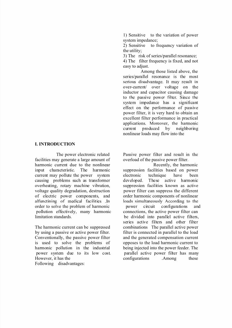
. Fig.3.Equivalent circuit of proposed active
power filter
Fig. 3 shows the equivalent circuit of the
proposed active power filter. It consistsof two voltage sources, one is the utility
and the other is the power converter. The
compensating voltage generated by the power converter is a dependent voltage
source whose voltage depends on the
harmonic components of the load
current. The equivalent circuit shown in
Fig. 3 can be further divided into thefundamental frequency equivalent circuit
and the harmonic frequency equivalentcircuit as shown in Fig. 4.
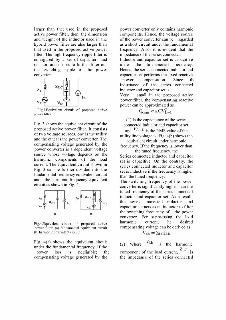
Fig.4.Equivalent circuit of proposed active power filter, (a) fundamental equivalent circuit
(b) harmonic equivalent circuit.
Fig. 4(a) shows the equivalent circuit
under the fundamental frequency .If the
power loss is negligible; thecompensating voltage generated by the
power converter only contains harmonic
components. Hence, the voltage source
of the power converter can be regardedas a short circuit under the fundamental
frequency. Also, it is evident that the
impedance of the series connectedInductor and capacitor set is capacitive
under the fundamental frequency.
Hence, the series connected inductor andcapacitor set performs the fixed reactive
power compensation. Since the
inductance of the series connected
inductor and capacitor set isVery small in the proposed active
power filter, the compensating reactive
power can be approximated as
(1) Is the capacitance of the series
connected inductor and capacitor set,
and is the RMS value of theutility line voltage is. Fig. 4(b) shows the
equivalent circuit under harmonic
frequency. If the frequency is lower thanthe tuned frequency, the
Series connected inductor and capacitor
set is capacitive. On the contrary, the
series connected inductor and capacitor set is inductive if the frequency is higher
than the tuned frequency.The switching frequency of the power
converter is significantly higher than the
tuned frequency of the series connected
inductor and capacitor set. As a result,the series connected inductor and
capacitor set acts as an inductor to filter
the switching frequency of the power converter. For suppressing the load
harmonic current, he desired
compensating voltage can be derived as
(2) Where is the harmonic
component of the load current, is
the impedance of the series connected

8/4/2019 A Noval Active Power Filter for Harmonic Supression
http://slidepdf.com/reader/full/a-noval-active-power-filter-for-harmonic-supression 6/12
inductor and capacitor set. If the power
converter can generate a voltage as
shown in (2), then this voltage isconverted into a compensating current
that is opposite to the load harmonic
current. Hence, the load harmoniccurrent can be suppressed. As shown in
Fig. 4(a), the fundamental component of
utility voltage drops on the seriesconnected inductor and capacitor set,
hence, the compensating voltage
generated by the power converter
consists only the harmonic components.In addition, (2) shows that the desired
compensation voltage is dependent on
the load harmonic current and the
impedance of the series connectedinductor and
Capacitor set. This value is smaller thanthe peak value of the utility voltage.
From the operation theory of the bridge
power converter, the dc bus voltage of a
power converter must be higher than the peak value of the compensating voltage.
Because the peak value of compensating
voltage is smaller than that of the utilityvoltage, the dc bus voltage in the
proposed active power filter can be
reduced significantly as compared withthe conventional parallel active power
filter whose voltage must be higher than
the peak value of the utility voltage.Consequently, the voltage rating of dc
capacitor and power electronic devices
can also be reduced. Besides, the ripple
current of the power converter isdependent on the dc bus voltage and
filter inductance. This implies that the
lower the dc bus voltage, the smaller filter inductance required for specified
ripple current limitation. Therefore, the
filter inductance used in the seriesconnected inductor and capacitor set is
smaller due to the lower dc bus voltage.
Besides, the high frequency response of
the proposed active power filter is better
than that of the conventional parallel
Active power filters due to the smaller filter inductance. Compared to the
conventional parallel active power filter,
it shows that the proposed active power filter uses three additional ac capacitors
to reduce the inductance of filter
inductor. In practice, the core of aninductor with large inductance is made
from the iron alloy, which results in the
bulky volume, heavy weight and large
loss. The core of an inductor with smallinductance can be made from the ferrite
materials, which have the characteristics
of small volume, light weight and low
eddy current loss .The EMI, generated by the switching of power converter, is
also dependent on the dc bus voltage.Therefore, the salient advantages of the
proposed active power filter are low
voltage rating of dc capacitor and power
switching devices, smaller filter inductance, smaller dimension, light
weight, good filter performance and low
EMI. Besides, the smaller filter inductance can improve the high
frequency response performance of this
active power filter. Since, the capacity of the dc bus voltage is dependent on the
amount of compensation current and not
the utility voltage, the application of the proposed active power filter could be
extended to a wider voltage range. In the
limited variable voltage application,
such as 220 V to 480 V, the change inthe main components is only the voltage
rating of series connected inductor and
capacitor set. In addition, the proposedactive power filter can be applied in
50/60 HZ power systems only adjusting
the parameters of the control circuit. For the conventional active power filter, the
voltage rating of both active and passive
components must be changed. The
hardware cost of the proposed active
8/4/2019 A Noval Active Power Filter for Harmonic Supression
http://slidepdf.com/reader/full/a-noval-active-power-filter-for-harmonic-supression 7/12
power filter is very competitive in the
nonlinear loads whose input is a diode-
rectifier or phase-controlled rectifier with a low level voltage below 480 V.
The conventional parallel active power
filter can supply the reactive power asthe variation of the load, and performs
the unity power factor compensation.
Nevertheless, the hybrid active power only supplies a fixed reactive power.
This results in the leading power factor,
as the load condition is light. The
reactive power compensation performance of the proposed active
power filter is similar to the hybrid
power filter supplying a fixed reactive
power.
III. CONTROL THEORY
Conventionally, the active power filter
was controlled by the current-mode.
However, it is hard to be implementedunder low filter inductance due to the
high switching ripple, and it may
generate multiple crossing during acarrier period of pulse-width modulator.
The phenomenon of multiple crossing
will result in more than one switchingoperation during a carrier period. In the
proposed active power filter, the voltage-
mode control is used. The three-phase power converter controlled by the
voltage-mode control acts as a voltage
amplifier with the gain represented by
(3)
Is the dc bus voltage and is theamplitude of the carrier signal of the
pulse-width modulator. Hence, thecontrol circuit of the voltage-mode
controller is used to determine a
reference voltage by dividing the desiredcompensating voltage by the gain shown
in (3). From the above section, it can be
found that the desired compensating
voltage generated by the power
converter is derivedFrom (2). Hence, the first control signal
where can be further derived from (2),
and it is represented as
(4)
Where L and C are the inductance andcapacitance of the series connected
inductor and capacitor set respectively,
and R is the stray loss of active power
filter. If the power converter cangenerate a harmonic voltage equal to the
first control signal and convert into a
compensating current by the series
connected inductor and capacitor set, theharmonic components of the load current
can be compensated theoretically. In practice, the filter performance is
degraded due to the parameters of the
series connected inductor and capacitor
set that may be varied due to age,variable frequency, production and
temperature. For improving the
compensating performance, the secondcontrol loop must be used to modify the
error of compensating result. Theconcept of the second control loop is based on the theory of conventional
hybrid power filter .The second control
signal is obtained by detecting the
harmonic components of the utilitycurrent and then amplifying with a gain ,
and it can be represented as
(5)Where is the harmonic component of the
utility current? If the power converter
can generate a voltage equal to thesecond control signal, the utility
harmonic current can be derived from
Fig. 4(b) and represented as
(6)
8/4/2019 A Noval Active Power Filter for Harmonic Supression
http://slidepdf.com/reader/full/a-noval-active-power-filter-for-harmonic-supression 8/12
is added to the denominator when the
power converter generates a voltage as
the second control signal From (6), it can be found that a term . Hence, the second
control loop is used to control the power
converter to act as a virtual harmonicresistor. The virtual harmonic resistor is
in series with the utility to block the
uncompensated harmonic components of load current flowing back to the utility.
In the proposed active power filter, the
first control loop acts as rough tuning,
and the second control loop is used for fine-tuning. Due to the use of voltage-
mode control in the proposed active
power filter, the series connected
inductor and capacitor set may result inhigh frequency oscillation between the
utility and the active power filters.Hence, the third control loop is applied
to avoid high frequency oscillation. The
third control loop is used to generate a
virtual harmonic resistor to be connectedin series with the series connected
inductor and capacitor set. The virtual
harmonic resistor acts as a harmonicdamper. It can be realized by using the
power converter to generate a harmonic
voltage that is proportional to theharmonic components of the active
power filter current. Hence, the third
control signal can be represented as
(7)
Where the current harmonic componentof the active power filter is. Hence, the
power converter can act as a virtual
harmonic resistor. A dc capacitor locatedat the dc bus of the voltage-source power
converter is used to supply a dc voltage
to the power converter and act as anenergy buffer. The dc bus voltage is
expected to be a constant voltage.
However, the virtual harmonic resistor inthe second and third control loops and
the switching loss of power converter
will consume the real power. Then, the
voltage variation at the dc bus cannot be
avoided. To maintain a constant dc bus
Voltage, the fourth control loop is used.The voltage regulation of the dc bus
voltage can be obtained by using the
power converter to generate afundamental voltage in phase or out-of-
phase with the fundamental component
of the active power filter current. Thefourth control signal can be represented
as
(8)
Where the fundamental component of
the active power filter is current. Then,the power converter acts as a
positive/negative fundamental resistor to
absorb/regenerate the real power from/tothe utility, so as to maintain the dc bus
voltage at a constant value. From the
above, the reference voltage of thecontrol circuit is the summation of the
first, second, third, and fourth control
signals, and it can be represented as
(9)In (9), the first control signal is the
dominant component. Hence, the
compensating voltage generated by the
power converter is almost the product of the impedance of the series connected
inductor and capacitor set and the
harmonic components of load current.
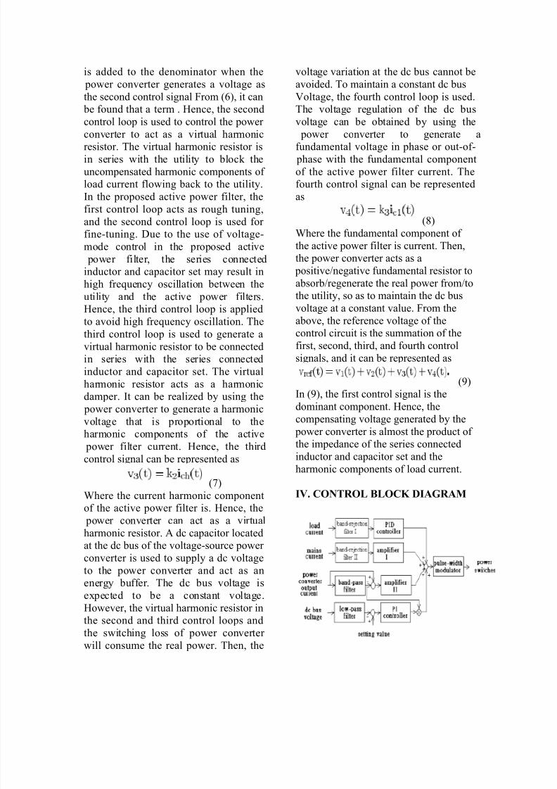
IV. CONTROL BLOCK DIAGRAM

8/4/2019 A Noval Active Power Filter for Harmonic Supression
http://slidepdf.com/reader/full/a-noval-active-power-filter-for-harmonic-supression 9/12
It consists of four control loops. From
Fig. 5, it can be found that four feedback
signals, namely the load current, theutility current, the output current of
power converter and the dc bus voltage
are used in the control circuit of the proposed active power filter to calculate
the reference voltage of the power
converter. The first control loop is usedto implement the product of harmonic
components of the load current and the
impedance of the series connected
inductor and capacitor set shown in (3).The load current is detected and sent to
the band-rejection filter I to filter out its
fundamental component. From (3), it can
be found that the product of harmoniccomponents of the load current and the
impedance of the series connectedinductor and capacitor set can be
obtained by feeding the harmonic
component of load current to a
Proportional Integral Differential (PID)controller.
TABLE I
MAJOR PARAMETERS OF
PROTOTYPE
Fig.5. Control block diagram of proposed active
power filter
The proportional, integral anddifferential coefficients are the resistor
R, capacitor C and inductor L shown in
(3), respectively. Then, the output of the
first control loop is obtained. For
TABLE II
COMPARISON RESULT
Avoiding the effect of noise, a low-pass
filter is used in the front of Differential
controller and a high-pass filter is
inserted at the end of Integral controller to reject the dc component due to the
initial condition. Since, the series
connected inductor and capacitor set is
located at the output of the power converter, the capacitor also can block
the dc component due to the initialcondition. Hence, the effect of the initial
condition caused by the switch-on of the
proposed active power filter can besuppressed. For improving the
compensating performance, the second
control loop is used to modify the error
of the compensating results of the firstcontrol loop. In the second control loop,
the detected utility current is sent to the band-rejection filter II to filter out thefundamental component. Then, the
uncompensated harmonic components of
the utility current are obtained. Theoutput of the band-rejection filter II is
fed to the amplifier I to
Obtain the output of the second control
loop.
The third control loop is used to generate
a virtual harmonic resistor to beconnected in series with the series
connected inductor and capacitor set to
act as a damper. The output current of the power converter is sent to a band-
pass filter to obtain the fundamental
component, and then, the detected output
current of the power converter and its

8/4/2019 A Noval Active Power Filter for Harmonic Supression
http://slidepdf.com/reader/full/a-noval-active-power-filter-for-harmonic-supression 10/12
fundamental component are fed to a sub
tractor to obtain the harmonic
components. The harmonic componentsare fed to amplifier II to obtain the
output of the third control loop.
The fourth control loop is used toregulate the dc bus voltage. The fourth
control loop comprises a low-pass filter
to filter out the dc bus voltage ripple anda subtract or to subtract a setting value
from the output of low-pass filter, then,
the sub tractor result is sent to a PI
controller. The output of the band-passfilter is the fundamental component of
active power filter current, and the
output of the fourth control loop is the
product of the output of the PI controller and the output of the band-pass filter.
Finally, the modulated signal can beobtained by summing the outputs of the
first, the second, the third and the fourth
control loops. Then, the modulated
signal is sent to a pulse-width modulator so as to drive the power switching
devices of the power converter.
V. EXPERIMENTAL RESULTS
For demonstrating the performance of
the proposed active power filter, a three-
phase 100KVA prototype is developed.
The major parameters of the prototype
are shown in Table I.The utility power is supplied by a three-
phase three-wire utility system with 380
V and 60 Hz. A comparison of the proposed active power filter and the
conventional parallel active power filter
is shown in Table II. Since theinductance of series connected inductor
and capacitor set is only 58 H, a ferrite
core can be used to reduce the power
Loss, weight and volume. Hence, the
volume and weight of the proposed
active power filter is evidently smaller than that of the conventional parallel
active power filter. In addition, thehardware cost is also reduced
significantly. The tested load is a 300
Kva UPS with a six-pulse rectifier
charger. Fig. 6 shows the experimentalresult of the proposed active power filter
in the steady state. The load current
shown in Fig. 6(c) is rich in harmonics;its total harmonic distortion (THD) is
51%. However, the THD of the utility
Fig.6. Experimental result of proposed active
power filter under steady state, (a) utility
voltage,(b) utility current, (c)load current, and
(d) output current of active power filter.
Current after compensating by the proposed active power filter is only
4.5%. The waveform of the utility
current after compensating by the proposed active power filter is nearly
sinusoidal. The test result shows that the
Harmonic suppression performance of
the proposed active power filter isexcellent. Fig 7 shows the experimental
result of the proposed active power filter
under switching-in the nonlinear load.As seen in Fig. 7(b).

8/4/2019 A Noval Active Power Filter for Harmonic Supression
http://slidepdf.com/reader/full/a-noval-active-power-filter-for-harmonic-supression 11/12
Fig.7. Experimental result of proposed active power filter under steady state, (a) utility
voltage,(b) utility current, (c)load current, and
(d) output current of active power filter
The utility current is still nearly
sinusoidal under the transient duration. Itverifies that the transient performance of
the proposed active power filter is
excellent.
In the industrial distribution power
system, a turbine generator is often usedas a back-up power. Because the
capacity of the turbine generator is not
large enough, the power source of theturbine generator can be regarded as a
weak power source.
Fig.8. Experimental result under weak power
source before applying active power filter.
Fig.9. Experimental result under weak power
source before applying active power filter.
The experimental results shown in Figs.8 and 9 are tested under the condition of
weak power source. The weak power
source is supplied by an 800 kva turbinegenerator. The load used in the test is the power equipment using a three-phase
rectifier in the input port. As seen in Fig.
8, the voltage waveform of the turbinegenerator is distorted seriously due to the
nonlinear load.
The THD of the utility voltage and theutility current are 12% and 25%
respectively. The distorted utility voltage
may disturb the normal operation of
power equipment itself or theneighboring load using the same power
source. Fig. 9 shows that both
waveforms of the voltage and current of the turbine generator are nearly
sinusoidal after applying the proposed
Active power The THD % of the turbinegenerator’s voltage and current are 4%
and 4.5%, respectively. Hence, this can
demonstrate that the proposed active power filter not only can suppress the
input current harmonics but also avoidthe waveform distortion of the voltage
under nonlinear loads.
VI. CONCLUSION
Recently, many power electronic
application technologies have been used

8/4/2019 A Noval Active Power Filter for Harmonic Supression
http://slidepdf.com/reader/full/a-noval-active-power-filter-for-harmonic-supression 12/12
to replace the role of conventional
passive elements in the distribution
power system for solving the problemsof power quality. The active power filter
is used to solve the harmonic problems
in the industrial power system, and this becomes popular gradually. However,
the wide use of the active power filter is
still limited due to the high cost and the power rating of power electronics. In
this paper, a novel active power filter is
proposed. The proposed active power
filter has the advantages of lower voltagerating for dc capacitor and power
switching devices, smaller filter
inductor, smaller dimension, light
weight, better filter performance and lowelectromagnetic interference (EMI). A
three-phase 100 kva active power filter is developed to demonstrate the
performance of the proposed method.
The experimental results show that the
proposed active power filter hasexcellent performance in suppressing
harmonic current. The hardware cost of
the proposed active power filter is verycompetitive in nonlinear loads whose
input is a diode-rectifier or phase-
controlled rectifier with a low levelvoltage below 480 V.
Recommended