A Multirate Field Construction Technique for Efficient Modeling of the Fields and Forces
within Inverter-Fed Induction Machines
Dezheng Wu, Steve Pekarek
School of Electrical and Computer EngineeringPurdue University
September 30, 2010
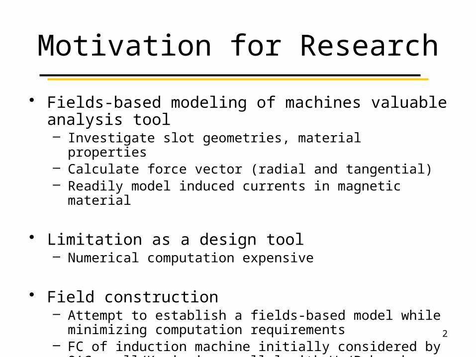
Motivation for Research
• Fields-based modeling of machines valuable analysis tool– Investigate slot geometries, material properties– Calculate force vector (radial and tangential)– Readily model induced currents in magnetic material
• Limitation as a design tool– Numerical computation expensive
• Field construction– Attempt to establish a fields-based model while minimizing
computation requirements– FC of induction machine initially considered by O’Connell/Krein in
parallel with Wu/Pekarek2
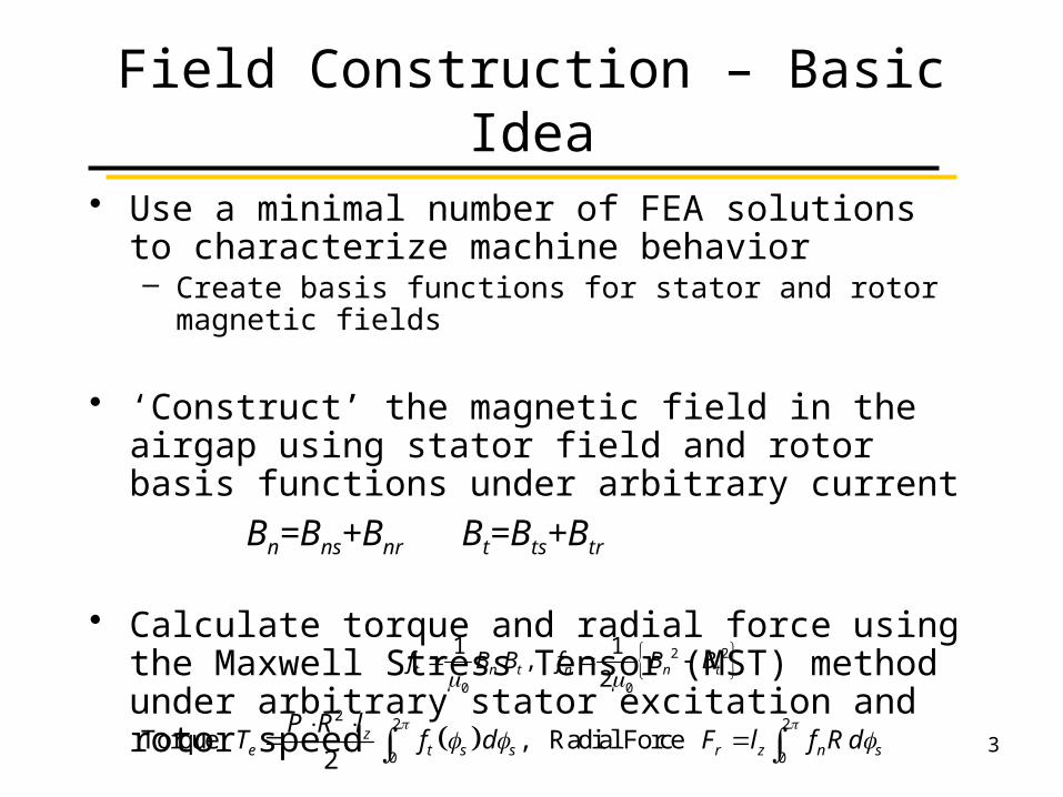
Field Construction – Basic Idea
• Use a minimal number of FEA solutions to characterize machine behavior – Create basis functions for stator and rotor magnetic fields
• ‘Construct’ the magnetic field in the airgap using stator field and rotor basis functions under arbitrary current
Bn=Bns+Bnr Bt=Bts+Btr
• Calculate torque and radial force using the Maxwell Stress Tensor (MST) method under arbitrary stator excitation and rotor speed
2 2
0 0
1 1. ,
2t n t n n tf B B f B B
2
2 2
0 0Torque , Radial Force
2z
e t s s r z n s
P R lT f d F l f R d
3
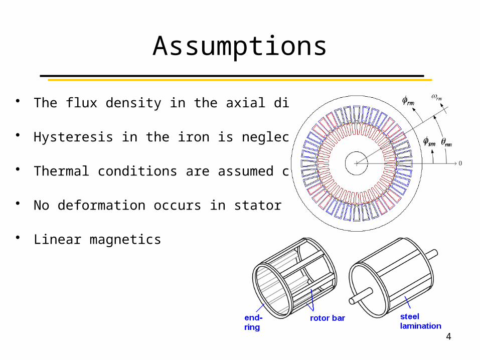
Assumptions
• The flux density in the axial direction is zero
• Hysteresis in the iron is neglected
• Thermal conditions are assumed constant
• No deformation occurs in stator and rotor teeth
• Linear magnetics
sm
rm
rm
4
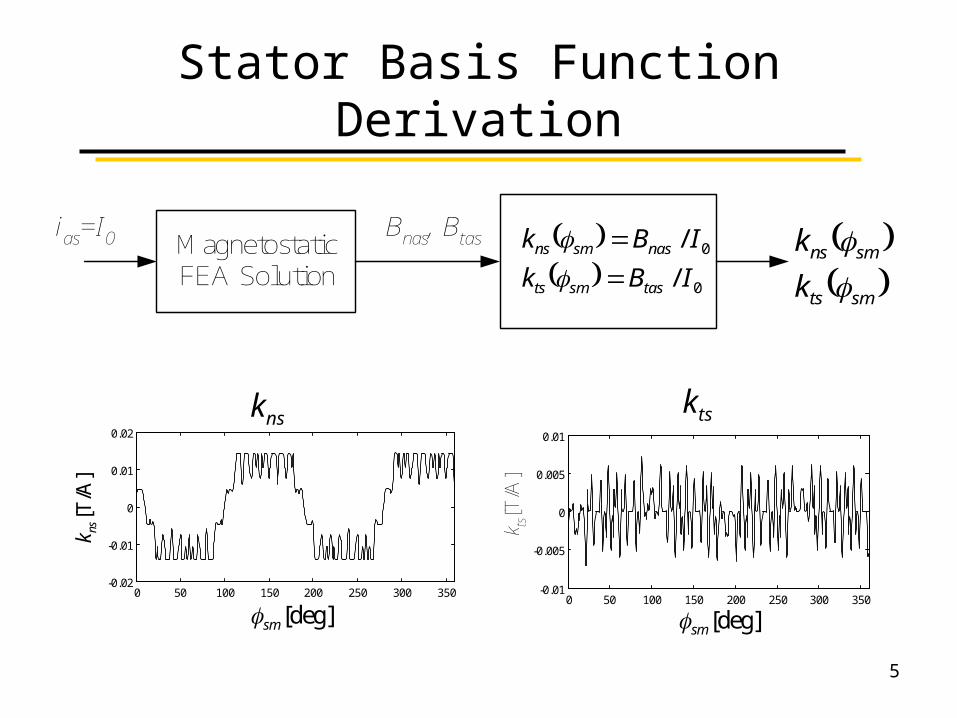
Stator Basis Function Derivation
MagnetostaticFEA Solution
ias=I0 Bnas, Btas smts
smns
k
k
0
0
/
/
IBk
IBk
tassmts
nassmns
0 50 100 150 200 250 300 350-0.02
-0.01
0
0.01
0.02
deg][sm
[T/A
]nsk
kns
0 50 100 150 200 250 300 350-0.01
-0.005
0
0.005
0.01
deg][sm
k ts[T
/A]
kts
5
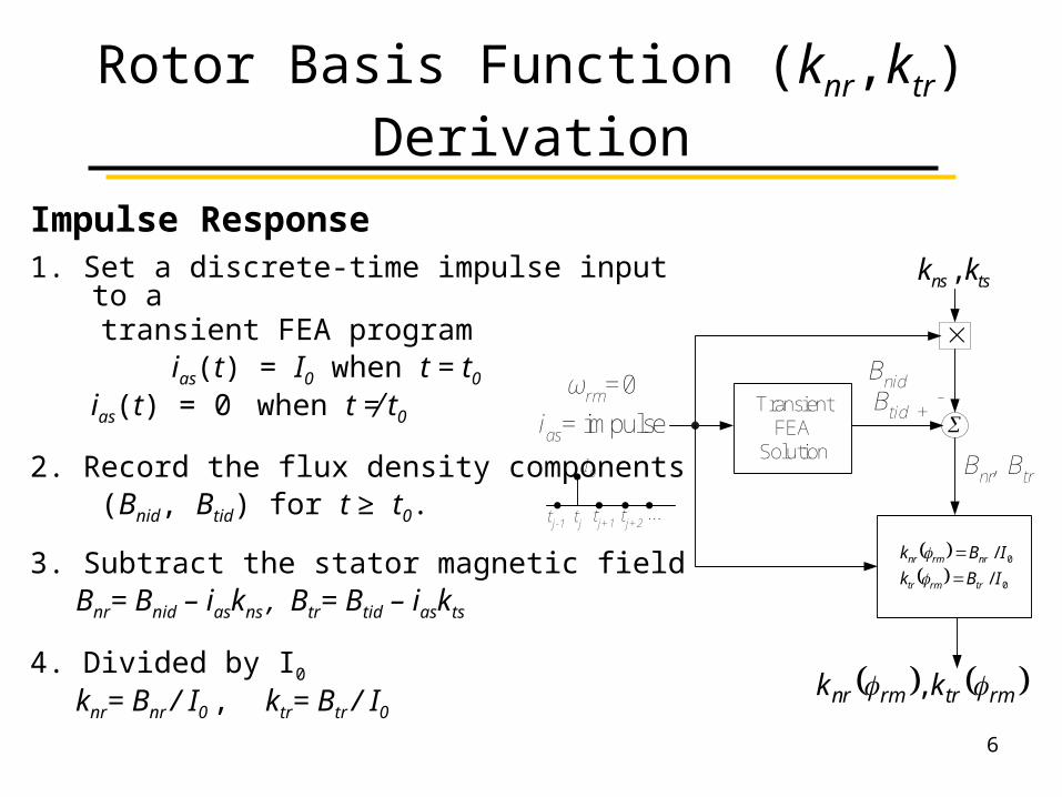
Rotor Basis Function (knr,ktr) Derivation
Impulse Response1. Set a discrete-time impulse input to a transient FEA program ias(t) = I0 when t = t0
ias(t) = 0 when t ≠ t0
2. Record the flux density components (Bnid, Btid) for t ≥ t0.
3. Subtract the stator magnetic field Bnr= Bnid – iaskns , Btr= Btid – iaskts
4. Divided by I0
knr= Bnr / I0 , ktr= Btr / I0
TransientFEA
Solution
ωrm=0
ias= impulse
Bnr, Btr
+-
rmtrrmnr kk ,
Bnid Btid
tjtj-1 tj+1 tj+2...
I0
tsns kk ,
0
0
/
/
IBk
IBk
trrmtr
nrrmnr
6
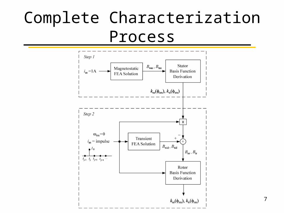
Complete Characterization Process
7
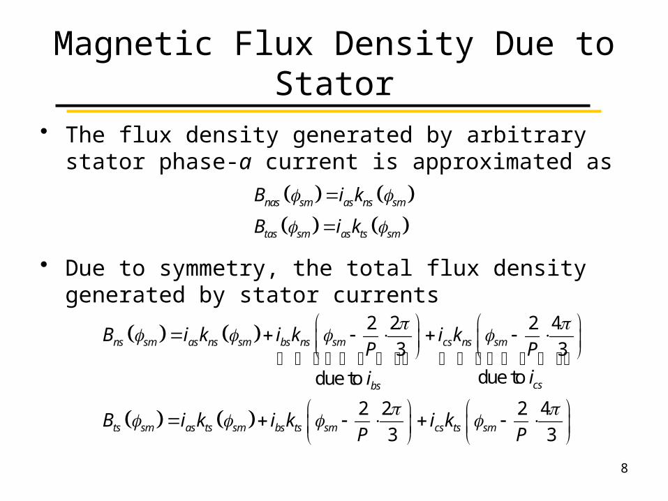
Magnetic Flux Density Due to Stator
• The flux density generated by arbitrary stator phase-a current is approximated as
• Due to symmetry, the total flux density generated by stator currents
nas sm as ns sm
tas sm as ts sm
B i k
B i k
2 2 2 4
3 3
due to due to
2 2 2 4
3 3
ns sm as ns sm bs ns sm cs ns sm
csbs
ts sm as ts sm bs ts sm cs ts sm
B i k i k i kP P
ii
B i k i k i kP P
8
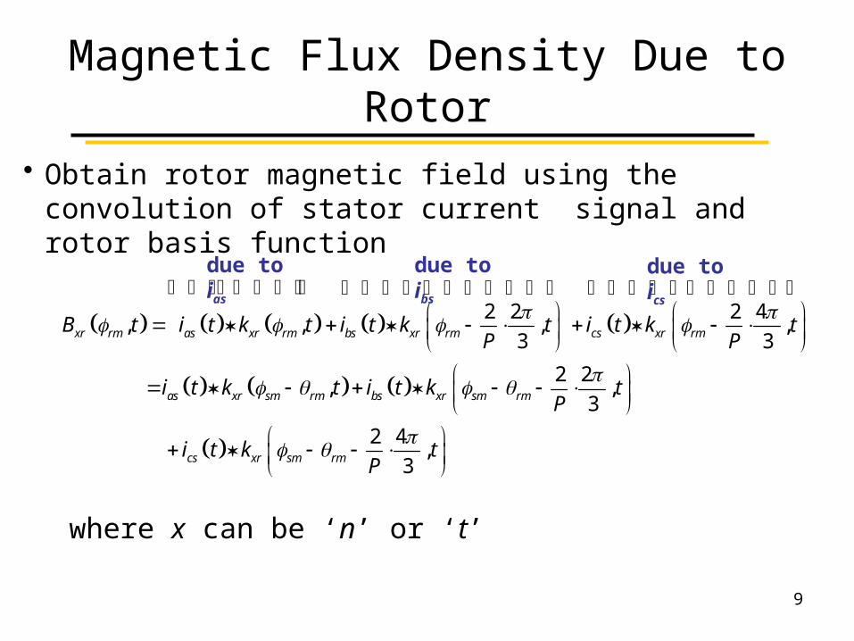
Magnetic Flux Density Due to Rotor
2 2 2 4, , , ,
3 3
2 2, ,
3
2 4,
3
xr rm as xr rm bs xr rm cs xr rm
as xr sm rm bs xr sm rm
cs xr sm rm
B t i t k t i t k t i t k tP P
i t k t i t k tP
i t k tP
• Obtain rotor magnetic field using the convolution of stator current signal and rotor basis function
where x can be ‘n’ or ‘t’
due to ias due to ibs due to ics
9
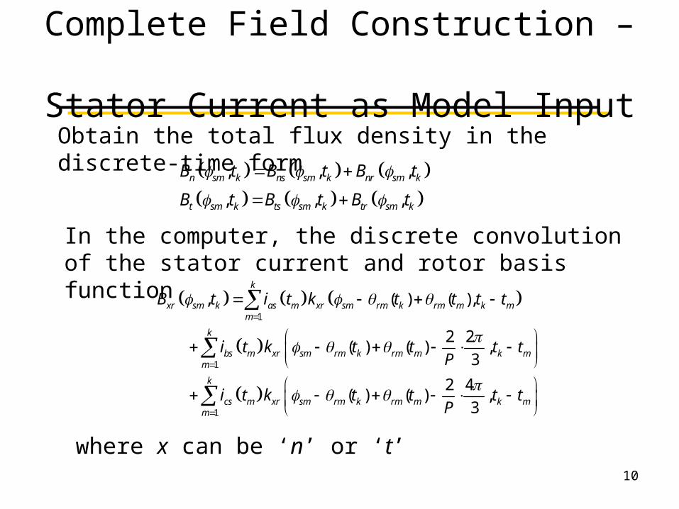
Complete Field Construction – Stator Current as Model Input
, , ,
, , ,
n sm k ns sm k nr sm k
t sm k ts sm k tr sm k
B t B t B t
B t B t B t
Obtain the total flux density in the discrete-time form
1
1
1
, ( ) ( ),
2 2( ) ( ) ,
3
2 4( ) ( ) ,
3
k
xr sm k as m xr sm rm k rm m k mm
k
bs m xr sm rm k rm m k mm
k
cs m xr sm rm k rm m k mm
B t i t k t t t t
i t k t t t tP
i t k t t t tP
In the computer, the discrete convolution of the stator current and rotor basis function
where x can be ‘n’ or ‘t’10
11
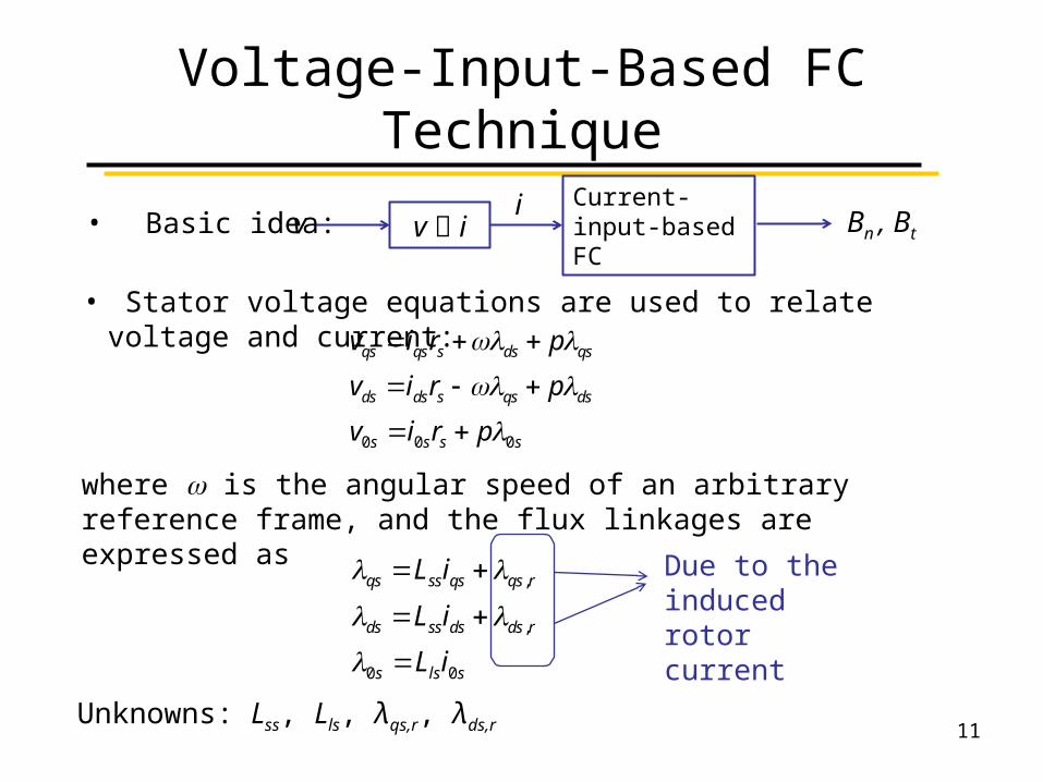
Voltage-Input-Based FC Technique
v iCurrent-input-based FC
iv Bn , Bt• Basic idea:
• Stator voltage equations are used to relate voltage and current:
0 0 0
qs qs s ds qs
ds ds s qs ds
s s s s
v i r p
v i r p
v i r p
,
,
0 0
qs ss qs qs r
ds ss ds ds r
s ls s
L i
L i
L i
where w is the angular speed of an arbitrary reference frame, and the flux linkages are expressed as
Due to the induced rotor current
Unknowns: Lss, Lls, λqs,r, λds,r
12
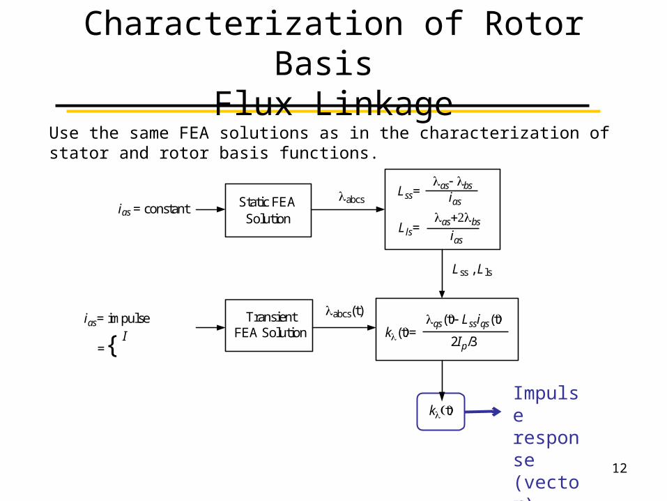
Characterization of Rotor Basis Flux Linkage
Use the same FEA solutions as in the characterization of stator and rotor basis functions.
Impulse response (vector)
Static FEASolution
TransientFEA Solution
ias = constant
ias= impulse
={
abcs(t)
abcs
Lss , Lls
kt
Lss=as bs
ias
Lls=as2bs
ias
k(t=qs(t Lssiqs(t
2Ip/3I
13
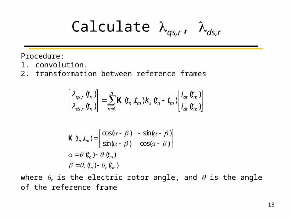
Calculate lqs,r, lds,r
Procedure: 1. convolution. 2. transformation between reference frames
,
1,
( ) ( )( , ) ( )
( ) ( )
nqs r n qs m
n m n mmds r n ds m
t i tt t k t t
t i t
K
cos( ) sin( )( , )
sin( ) cos( )
( ) ( )
( ) ( )
n m
n m
r n r m
t t
t t
t t
K
where qr is the electric rotor angle, and q is the angle of the reference frame
14
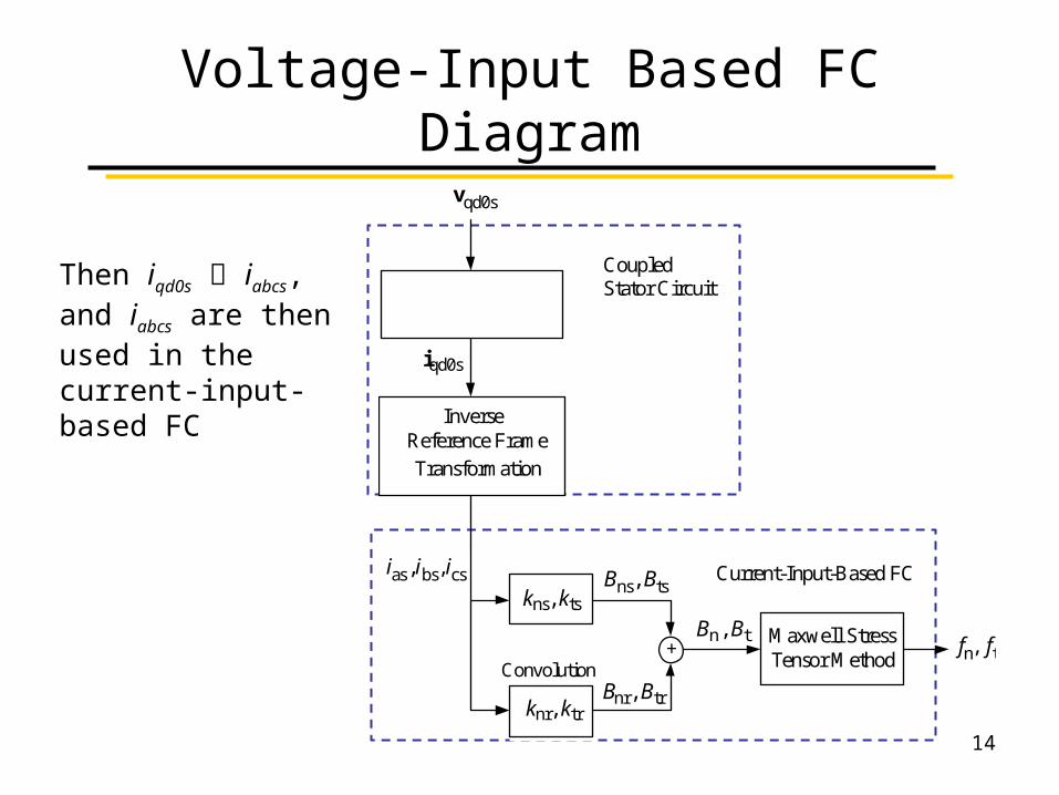
Voltage-Input Based FC Diagram
Then iqd0s iabcs, and iabcs are then used in the current-input-based FC
Bn , Bt Maxwell StressTensor Method
fn, ft+
Bns, Bts
Bnr, Btr
InverseReference FrameTransformation
iqd0s
vqd0s
ias, ibs, ics Current-Input-Based FC
CoupledStator Circuit
kns, kts
knr, ktr
Convolution
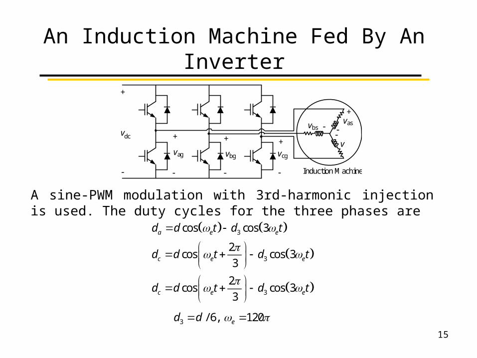
An Induction Machine Fed By An Inverter
15
3
3
3
cos cos 3
2cos cos 3
3
2cos cos 3
3
a e e
c e e
c e e
d d t d t
d d t d t
d d t d t
3 / 6, 120ed d
A sine-PWM modulation with 3rd-harmonic injection is used. The duty cycles for the three phases are
v
Induction Machine
dc
vag
+
vbg
+
vcg
+
+
+vas
vbs
v
Challenges
16
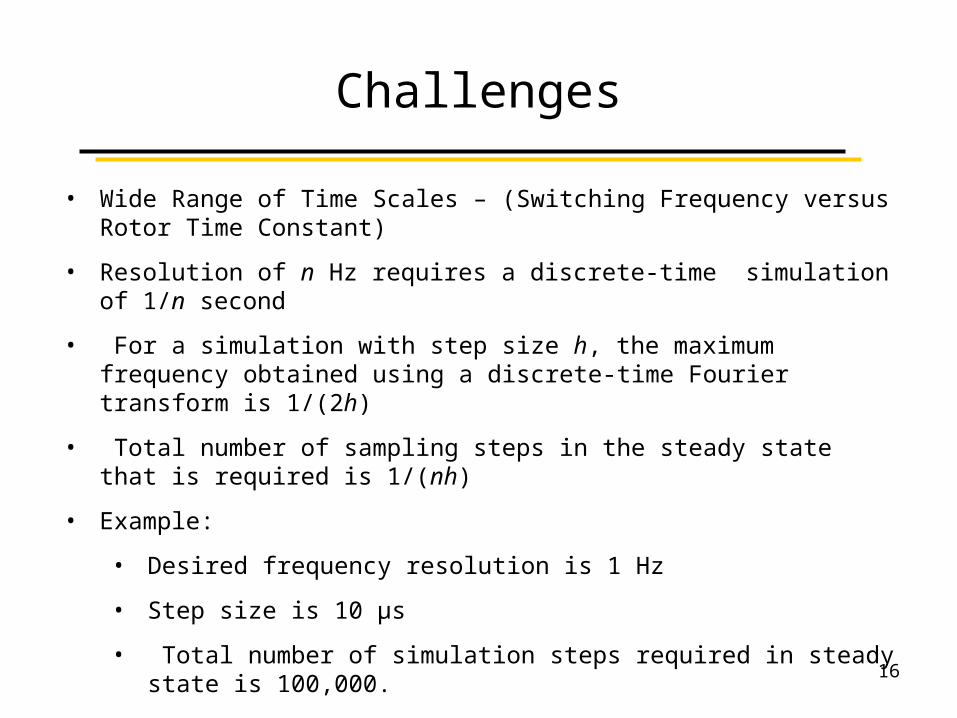
• Wide Range of Time Scales – (Switching Frequency versus Rotor Time Constant)
• Resolution of n Hz requires a discrete-time simulation of 1/n second
• For a simulation with step size h, the maximum frequency obtained using a discrete-time Fourier transform is 1/(2h)
• Total number of sampling steps in the steady state that is required is 1/(nh)
• Example:
• Desired frequency resolution is 1 Hz
• Step size is 10 μs
• Total number of simulation steps required in steady state is 100,000.
• The large size of rotor basis function and amount of sampling steps add difficulties to computer memory and the computational effort.
Computational Burden of FC
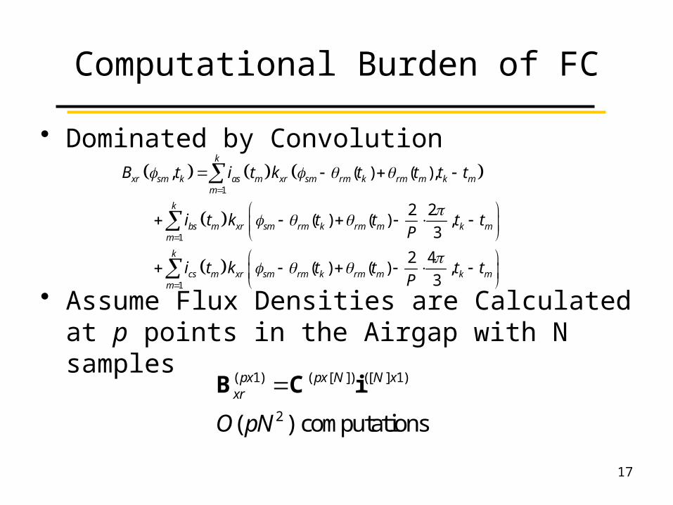
• Dominated by Convolution
• Assume Flux Densities are Calculated at p points in the Airgap with N samples
1
1
1
, ( ) ( ),
2 2( ) ( ) ,
3
2 4( ) ( ) ,
3
k
xr sm k as m xr sm rm k rm m k mm
k
bs m xr sm rm k rm m k mm
k
cs m xr sm rm k rm m k mm
B t i t k t t t t
i t k t t t tP
i t k t t t tP
( 1) ( [ ]) ([ ] 1)
2( ) computations
px px N N xxr
O pN
B C i
17
Multirate Field Construction
18
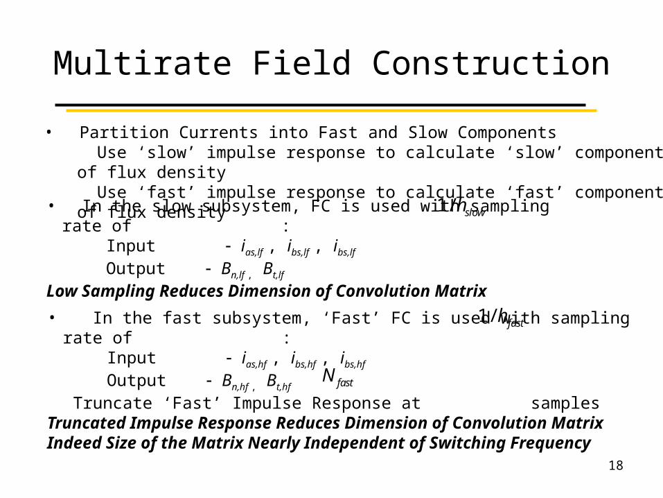
• In the slow subsystem, FC is used with sampling rate of : Input ias,lf , ibs,lf , ibs,lf
Output Bn,lf , Bt,lf
Low Sampling Reduces Dimension of Convolution Matrix
• In the fast subsystem, ‘Fast’ FC is used with sampling rate of : Input ias,hf , ibs,hf , ibs,hf
Output Bn,hf , Bt,hf
Truncate ‘Fast’ Impulse Response at samples Truncated Impulse Response Reduces Dimension of Convolution MatrixIndeed Size of the Matrix Nearly Independent of Switching Frequency
1/ slowh
1/ fasth
fastN
• Partition Currents into Fast and Slow Components Use ‘slow’ impulse response to calculate ‘slow’ component of flux density Use ‘fast’ impulse response to calculate ‘fast’ component of flux density
Multirate Field Construction
19
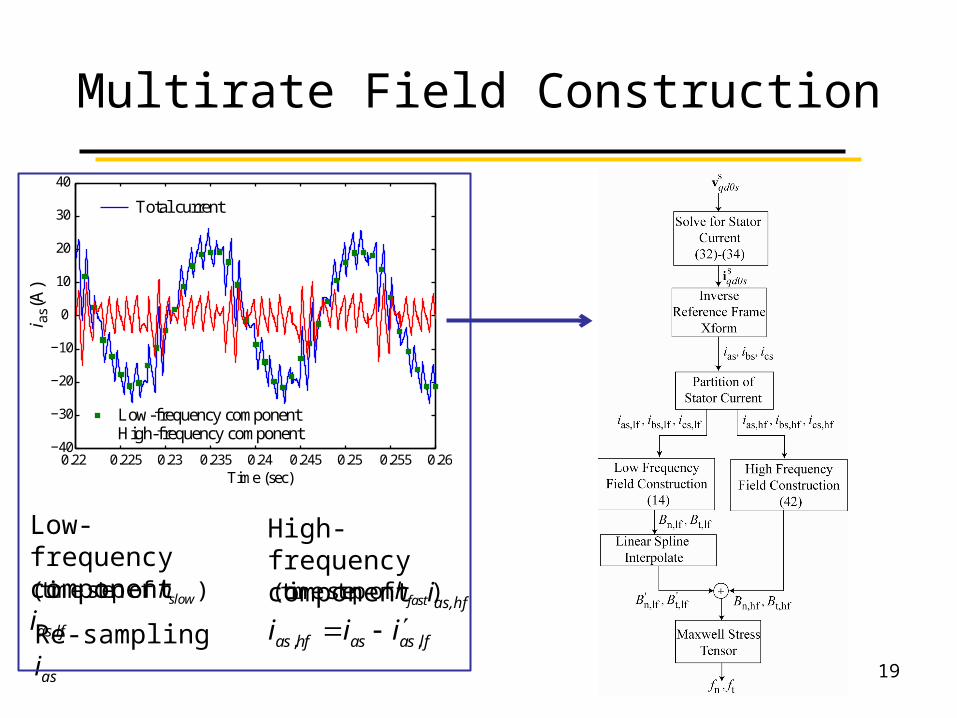
, ,as hf as as lfi i i
High-frequency component ias,hf
Low-frequency component ias,lf
Re-sampling ias
0.22 0.225 0.23 0.235 0.24 0.245 0.25 0.255 0.26−40
−30
−20
−10
0
10
20
30
40
Time (sec)
i as (
A)
Total current
Low-frequency componentHigh-frequency component
(time step of )slowh (time step of )fasth
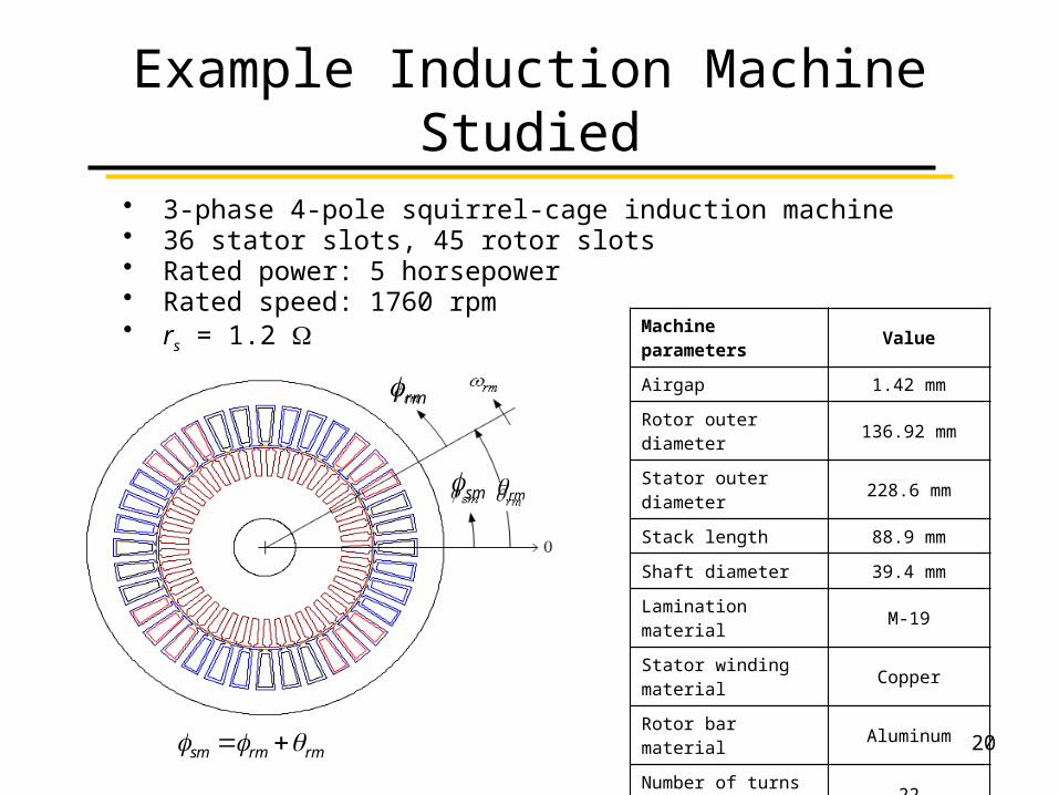
Example Induction Machine Studied
• 3-phase 4-pole squirrel-cage induction machine• 36 stator slots, 45 rotor slots• Rated power: 5 horsepower• Rated speed: 1760 rpm• rs = 1.2
sm
rm
rm
sm rm rm
Machine parameters Value
Airgap 1.42 mm
Rotor outer diameter 136.92 mm
Stator outer diameter 228.6 mm
Stack length 88.9 mm
Shaft diameter 39.4 mm
Lamination material M-19
Stator winding material
Copper
Rotor bar material Aluminum
Number of turns per coil
22
Number of coils per phase
6 coils in series connection
20
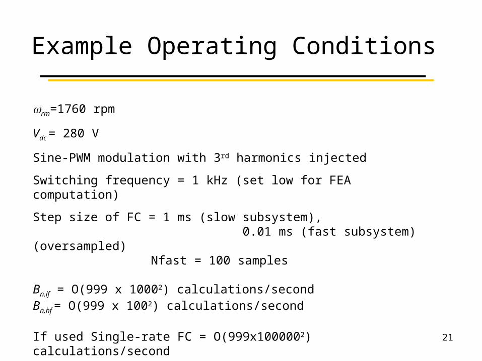
Example Operating Conditions
21
wrm=1760 rpm
Vdc = 280 V
Sine-PWM modulation with 3rd harmonics injected
Switching frequency = 1 kHz (set low for FEA computation)
Step size of FC = 1 ms (slow subsystem), 0.01 ms (fast subsystem) (oversampled)
Nfast = 100 samples
Bn,lf = O(999 x 10002) calculations/secondBn,hf = O(999 x 1002) calculations/second
If used Single-rate FC = O(999x1000002) calculations/second
Step size of FEA = 0.01 ms
0.2 0.21 0.22 0.23 0.24 0.25 0.26−40
−30
−20
−10
0
10
20
30
40
Time (sec)
i as (
A)
FEAFC
0 500 1000 1500 2000 2500 3000 3500 40000
1
2
3
4
5
Frequency (Hz)
i as (
A)
FEAFC
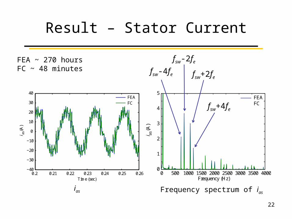
Result – Stator Current
22
FEA ~ 270 hoursFC ~ 48 minutes
ias Frequency spectrum of ias
fsw-2fe
fsw+2fefsw-4fe
fsw+4fe
0 500 1000 1500 2000 2500 3000 3500 40000
1
2
3
4
5
Frequency (Hz)
Tor
que
(Nm
)
FEAFC
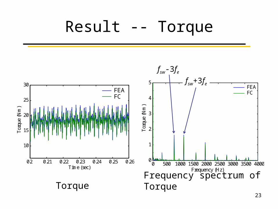
Result -- Torque
23
Torque Frequency spectrum of Torque
fsw-3fe
fsw+3fe
0.2 0.21 0.22 0.23 0.24 0.25 0.26
10
15
20
25
30
Tor
que
(Nm
)
Time (sec)
FEAFC
Conclusions
• Method to efficiently model fields and forces in inverter-fed induction machines presented– Requires Minimal FEA Evaluations (at Standstill)
• Multi-rate Leads to Relatively Low Computation Burden – Does Not Increase with Switching Frequency
• Can be Applied to Flux Density Field Construciton in Iron, i.e. Calculate Core Loss
• Requires a Partition of Time Scales
24
Acknowledgement
• This work is made possible through the Office of Naval Research Grant no. N00014-02-1-0623.
25
Recommended