University of Central Florida University of Central Florida
STARS STARS
Retrospective Theses and Dissertations
1986
A Microsequenced Prolog Inference Engine A Microsequenced Prolog Inference Engine
Jeffrey J. Ferguson University of Central Florida
Part of the Systems and Communications Commons
Find similar works at: https://stars.library.ucf.edu/rtd
University of Central Florida Libraries http://library.ucf.edu
This Masters Thesis (Open Access) is brought to you for free and open access by STARS. It has been accepted for
inclusion in Retrospective Theses and Dissertations by an authorized administrator of STARS. For more information,
please contact [email protected].
STARS Citation STARS Citation Ferguson, Jeffrey J., "A Microsequenced Prolog Inference Engine" (1986). Retrospective Theses and Dissertations. 4906. https://stars.library.ucf.edu/rtd/4906
A MICROSEQUENCED PROLOG INFERENCE ENGINE
BY
JEFFREY JAMES FERGUSON B.S.E.E., Ohio Northern University, 1982
RESEARCH REPORT
Submitted in partial fulfillment of the requirements for the degree of Master of Science in Engineering in the
Graduate Studies Program of the College of Engineering University of Central Florida
Orlando, Florida
Summer Term 1986
ABSTRACT
Prolog is a symbolic logic language presently emerging among
numerous expert system designs. The architecture for a microsequenced
Prolog machine (UPM) capable of providing the basic language features to
a host computer is proposed. The Prolog machine functions are
partitioned into three processor components -- Input/Output, Memory, and
Central (CPU), where the design of the Central Processor is emphasized.
Detailed discussion outlines the CPU facilities used to implement the
forward-chaining and backtracking functions for the UPM. The UPM
features are compared to the PLM-1, a microsequenced Prolog inference
engine under development at University of California, Berkeley. An
emulation of the entire algorithm is provided, as well as a proposed
microengine and associated microstore.
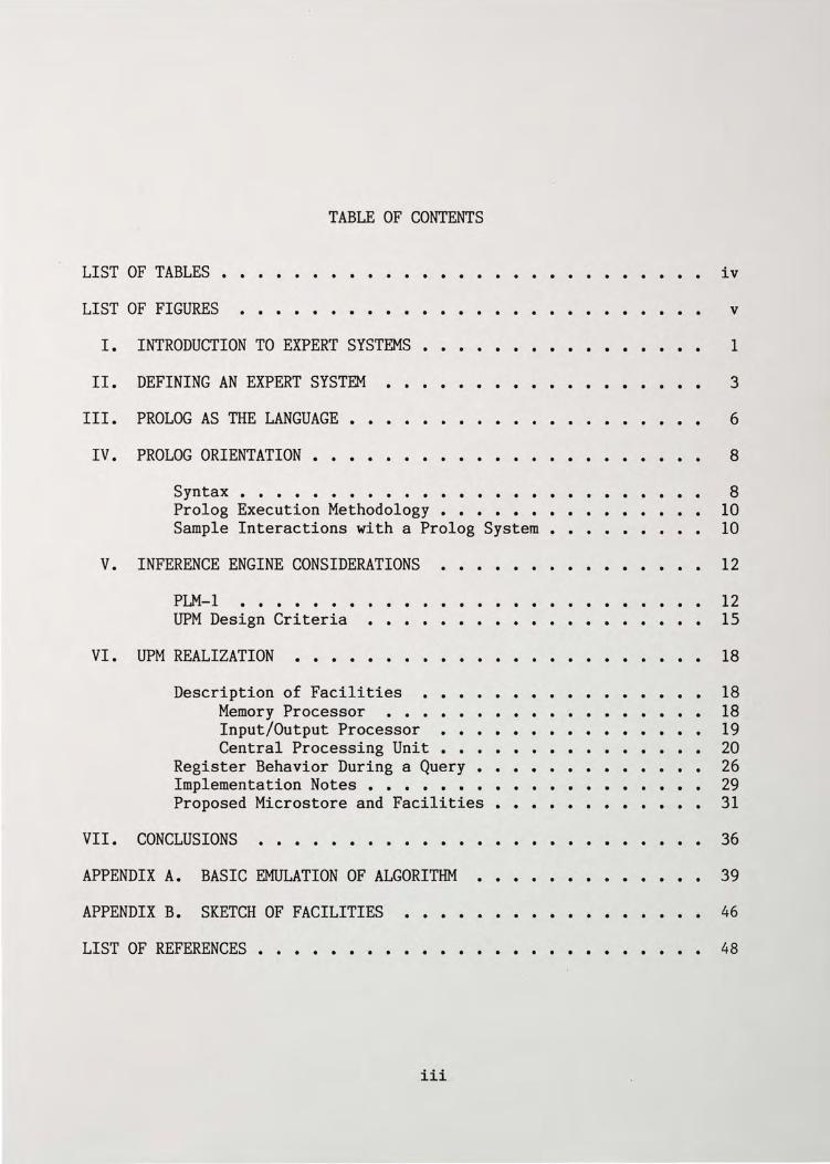
TABLE OF CONTENTS
LIST OF TABLES • . . . . . . . . . . . . . . . . LIST OF FIGURES . . . . . . .
I. INTRODUCTION TO EXPERT SYSTEMS . . . . . . II. DEFINING AN EXPERT SYSTEM . . . . . . . . . . .
III. PROLOG AS THE LANGUAGE • . . . . . . . IV. PROLOG ORIENTATION ••
Syntax • • • • • • • Prolog Execution Methodology • • • Sample Interactions with a Prolog System •
V. INFERENCE ENGINE CONSIDERATIONS
PLM-1 UPM Design Criteria . . . .
VI. UPM REALIZATION . . . . . . . . . . . Description of Facilities • • • • • • •
Memory Processor • • • • • • • • • • • • Input/Output Processor • • • • • • • • • • Central Processing Unit • • • • • •
Register Behavior During a Query Implementation Notes • • • • • • Proposed Microstore and Facilities • • • • • •
VII. CONCLUSIONS . . . . . . . . . . . . .
. .
APPENDIX A. BASIC EMULATION OF ALGORITHM . . . . . APPENDIX B. SKETCH OF FACILITIES . . . . . LIST OF REFERENCES • • • • • • • • • . . .
iii
iv
v
1
3
6
8
8 10 10
12
12 15
18
18 18 19 20 26 29 31
36
39
46
48
LIST OF TABLES
1. FIFTH GENERATION KNOWLEDGE PROCESSOR GOALS . . . . . . . . . 2
2. PARTIAL RULE BASE FOR A BOTANY SYSTEM . . . • . . 4
3. PLM-1 WORKING REGISTERS . . . . . . . . . . . . . . . . . 14
4. CORRELATION BETWEEN PLM-1 AND UPM REGISTERS . . . . . . • . 17
s. REGISTER/FILE/STACK ROLES IN THE UPM • . . . 22
6. DATA BUS PROTOCOL . . . . . . . . . . . • . . . . . . . . 30
iv
1.
2.
3.
4.
s.
6.
LIST OF FIGURES
UPM Emulator Interactions
Block Diagram of Facilities
Flowchart of CPU Actions • •
. . . . . . . . . . . . . . . . . . . . . .
. . . . . . . . . . . Flowchart of Memory Processor Actions • • • . . . . . Register/File/Stack (RFS) Behavior During a Query . . . . . Microstore Contents
v
11
21
23
25
26
33
I. INTRODUCTION
To provide for the information demands of the 1990s, fifth
generation computer systems are now evolving - design emphasis for this
generation of machines considers not only the ongoing efforts to
increase speed and density, but to include utilization of more varied
media, higher software productivity, and application of information
technology to those areas in which existing information technology has
not yet been applied.
Conventional (von Neumann) computers, structured primarily to
perform numeric-intensive, sequential programs are being replaced by
architectures which rely primarily on parallel processing, due to the
fact that device speed has approached a limit for sequential processing.
A second reason for the anticipated replacement of the traditional von
Neumann design is the difficulty in realizing basic functions for non
numeric processing of speech, text, graphics, and patterns, and for
artificial intelligence fields such as inference, association, and
learning. For this reason, reference to "fifth-generation" machines
generally implies reference to machines which provide knowledge
information processing systems.
The Japanese are a major force in spearheading the efforts to a
achieve new architectures for a fifth-generation knowledge information
processor. Their function goals, as outlined in Table 1, are indicative
of many expert systems presently under development{l}.
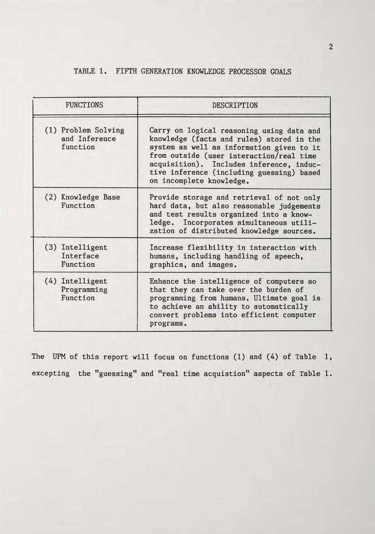
TABLE 1. FIFTH GENERATION KNOWLEDGE PROCESSOR GOALS
FUNCTIONS DESCRIPTION
(1) Problem Solving and Inference function
(2) Knowledge Base Function
(3) Intelligent Interface Function
(4) Intelligent Programming Function
Carry on logical reasoning using data and knowledge (facts and rules) stored in the system as well as information given to it from outside (user interaction/real time acquisition). Includes inference, inductive inference (including guessing) based on incomplete knowledge.
Provide storage and retrieval of not only hard data, but also reasonable judgements and test results organized into a knowledge. Incorporates simultaneous utilization of distributed knowledge sources.
Increase flexibility in interaction with humans, including handling of speech, graphics, and images.
Enhance the intelligence of computers so that they can take over the burden of programming from humans. Ultimate goal is to achieve an ability to automatically convert problems into efficient computer programs.
2
The UPM of this report will focus on functions (1) and (4) of Table 1,
excepting the "guessing" and "real time acquistion" aspects of Table 1.
II. DEFINING AN EXPERT SYSTEM
A key aspect of expert systems technology is that at least three
kinds of knowledge have been generally identified as useful in symbolic
provlem solving. These are facts, relations between these facts (also
referred to as rules), and methods for using these relations in problem
solving. Knowledge engineering is the subfield of artificial
intelligence concerned with applying knowledge to solve problems that
ordinarily require human intelligence. Solving problems in areas of
human expertise such as engineering, medicine, and financial advising
requires specialized know-how comparable to what a human expert
possesses, hence the term "expert system." The method used for problem
solving is the facet most heavily dependent on the application
environment. For example, by searching for confirming evidence, a
diagnostic medical expert system might reason backwards from all
potential diseases it knows. Only when it encountered sufficient
disconfirming data on the patient's condition would it proceed from one
disease to the next candidate{2}. This "backward chaining" methodology
offers contrast to a more traditional approach, that of the forward
chaining, or data-driven engine{3}.
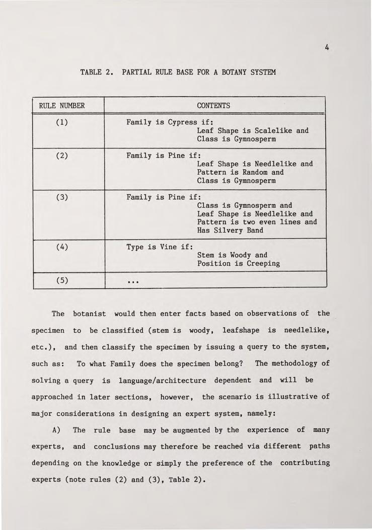
The expert system employing a forward chainings type of inference
mechanism is best illustrated by an example. A user-interactive botany
expert system would contain a collection of rules adhering perhaps to
the classical "if-then" structure , as in the following:{4}
3
4
TABLE 2. PARTIAL RULE BASE FOR A BOTANY SYSTEM
RULE NUMBER CONTENTS
(1) Family is Cypress if: Leaf Shape is Scalelike and Class is Gymnosperm
(2) Family is Pine if: Leaf Shape is Needlelike and Pattern is Random and Class is Gymnosperm
(3) Family is Pine if: Class is Gymnosperm and Leaf Shape is Needlelike and Pattern is two even lines and Has Silvery Band
(4) Type is Vine if: Stem is Woody and Position is Creeping
(5) ...
The botanist would then enter facts based on observations of the
specimen to be classified (stem is woody, leafshape is needlelike,
etc.), and then classify the specimen by issuing a query to the system,
such as: To what Family does the specimen belong? The methodology of
solving a query is language/architecture dependent and will be
approached in later sections, however, the scenario is illustrative of
major considerations in designing an expert system, namely:
A) The rule base may be augmented by the experience of many
experts, and conclusions may therefore be reached via different paths
depending on the knowledge or simply the preference of the contributing
experts (note rules (2) and (3), Table 2).
5
B) As a consequence of A), facilities to accomodate a failure in
investigating a possible solution path must exist. This mechanism is
referred to as backtracking.
C) The ability of the system to ask the user questions in the
event that no rule can be found that unequivocably leads to a family
classification.
D) In the event of insufficient facts and/or rules to obtain a
classification, the advanced expert system will attempt to yield a "best
guess" of the family using a deductive reasoning scheme. This may
incorporate certainty factors which designate the level of confidence or
validity the data possesses{2}. This is similar to a doctor diagnosing
pneumonia to be the ailment of a patient with a severe cough, high
temperature, and shortness of breath, even though fluid build-up in the
lungs is not yet evident. Certainty factors will not be included in the
proposed expert system.
E) Expert systems are distinguished from other artificial
intelligence programs in that their power is derived from the knowledge
contained in the database, rather than from pre-designed heuristics and
search methods. For this reason, explanation facilities to aid the user
and justify conclusions are an important aspect of a well-rounded expert
system.
Regardless · of their differences in technique, expert systems
consist of a database to hold rules, facts, and relationships, an
inference engine to arrive at conclusions, and an input/output
controller to facilitate communication with the programmer/user.
III. PROLOG AS THE LANGUAGE
For the reasons enumerated in section I, numeric-intensive
languages are inappropriate for the symbolic, image, and list processing
inherent in the application environment of most expert systems.
Although early attempts at artificial intelligence have employed top
down (von Neumann) formats consisting of more than 1000 "if-then" checks
to arrive at conclusions, essentially two languages which contrast this
solution methodology have risen to the forefront of artificial
intelligence
specifically:
processing,
- Prolog and Lisp. Prolog has many parallels with Lisp,
Both are interactive languages designed for symbolic data
and neither explicitly incorporates the machine-oriented
concepts of assignment and references. Prolog, however, offers further
benefits in many aspects, when compared with Lisp{S}:
A) General record structures take the place of Lisp's s- _
expressions. An unlimited number of different record types may be used.
Records with any number of fields are possible, and there are no type
restrictions on the fields of a record.
B) Pattern matching replaces the use of selector and constructor
functions for operating on structured data.
C) Procedures may have multiple outputs as well as multiple
inputs.
D) Input and output arguments of a procedure do not have to be
distinguished in advance, but may vary from one call to another.
Procedures may thus be multi-purpose.
6

7
E) Procedures may generate, via backtracking, a sequence of
alternative results.
F) An "incomplete" data structure (containing free var.iables) may
be returned as a procedure's output. The free variables can later be
filled in by other procedures. The programmer need not be concerned
with the status of a variable (assigned or unassigned) since this status
is handled invisibly by the inference engine. This results in the
impossibility of encountering an error condition due to an "undefined"
operation - at worst Prolog would be unable to generate a solution with
100 percent surety due to insufficient relations in its database.
G) Program and data are identical in form, thus significantly
reducing the front end burden of programmer orientation.
The resulting overall simplicity of Prolog (in adherence with
fifth-generation design criteria), coupled with its relative youth in
the potpourri of programming languages, make it an ideal candidate for a
prototype expert system. The UPM described will implement the features
of C), D), E), F), and G) enumerated above.
IV. PROLOG ORIENTATION
Since Prolog is not yet widely known (but nonetheless already
suffering from the ever-present problem of being syntactically system
dependent), a brief presentation of features germane to understanding
the inference engine design and emulator routine for the UPM is now
undertaken.
Syntax{6}
The primitive Prolog expression is called a clause. An example is:
father of(adam,john). (1)
"Father of" is considered the head of the clause and the arguments are
"adam" and "john." A rule exists when the head of the clause is
followed by a body consisting of a number (possibly zero) of goals
(alternatively referred to as subgoals or procedure calls).
The clause in (1) is termed a fact and might be spoken in English
as, "Adam is the father of John," although the order of interpretation
is entirely programmer/user dependent as long as consistency is
maintained. Other facts might be:
valuable(gold).
pretty(sally,marie,amy).
The three clauses above would be considered to have an arity of 2, 1,
and 3 respectively, where arity refers to the number of arguments.
8
(2)
(3)
9
Facts obey the following syntax rules:
1) A fact is a clause with zero procedure calls.
2) Facts are finalized with a period.
3) Arguments are literals as indicated by the first letter being a
small letter of the alphabet.
An example of a rule would be:
grandfather of(X,Z):=father of(X,Y),father of(Y,Z). (4)
The rule of (4) might be interpreted as "The grandfather of any X will
be Z if the father of X is Y and the father of Y is Z." Rules obey the
following syntax and inference guidelines:
1) ":=" seperates the head from the body.
2) Arguments with capital letters at the beginning designate
variables.
3) The ordering of the goals in the clause indicates control
information to the inference engine (subgoal satisfaction is attempted ·
in a left-to-right order).
4) Rules are finalized with a period.
Queries are issued to the Prolog system following the insertion of \
available rules and facts into the database. They are of the following
form:
grandfather of(V,george)? (5)
Queries only have a head and must terminate with a question mark. The
effect of the query in equation (5) is to ask, "Find some V which has
George as a grandfather." The user may elicit a "true/false" response
10
by entering a query already containing literals, as in:
grandfather of(albert,george)? (6)
Effectively asking "Is George the grandfather of Albert?."
Finally, the entry of ";" after an already successful unification
indicates the desire for forced backtracking, or to say "go back and
find additional solutions, if possible."
Facilities found in many Prolog implementations not covered in the
UPM design are the "cut" and mathematical operations.
Prolog Execution Methodology
To execute a goal (initially entered as a query), the system
searches for the first clause in the rule and fact base whose head
matches or unifies with the goal. If a match is found, the matching
clause is then activated and execution (from left to right) of each of
the goals of its body (unless a fact, whereby unification of literals to
variables is performed) follows in turn. If at any time, the system
fails to find a match for a goal, it backtracks by rejecting the most
recently activated clause (undoing any substitutions made on the match
with the head of the clause). It proceeds by reconsidering the original
goal which activated the rejected clause, and tries to find a subsequent
clause which also matches the goal.{5} This search for alternate rule
clauses provides an "or" feature.
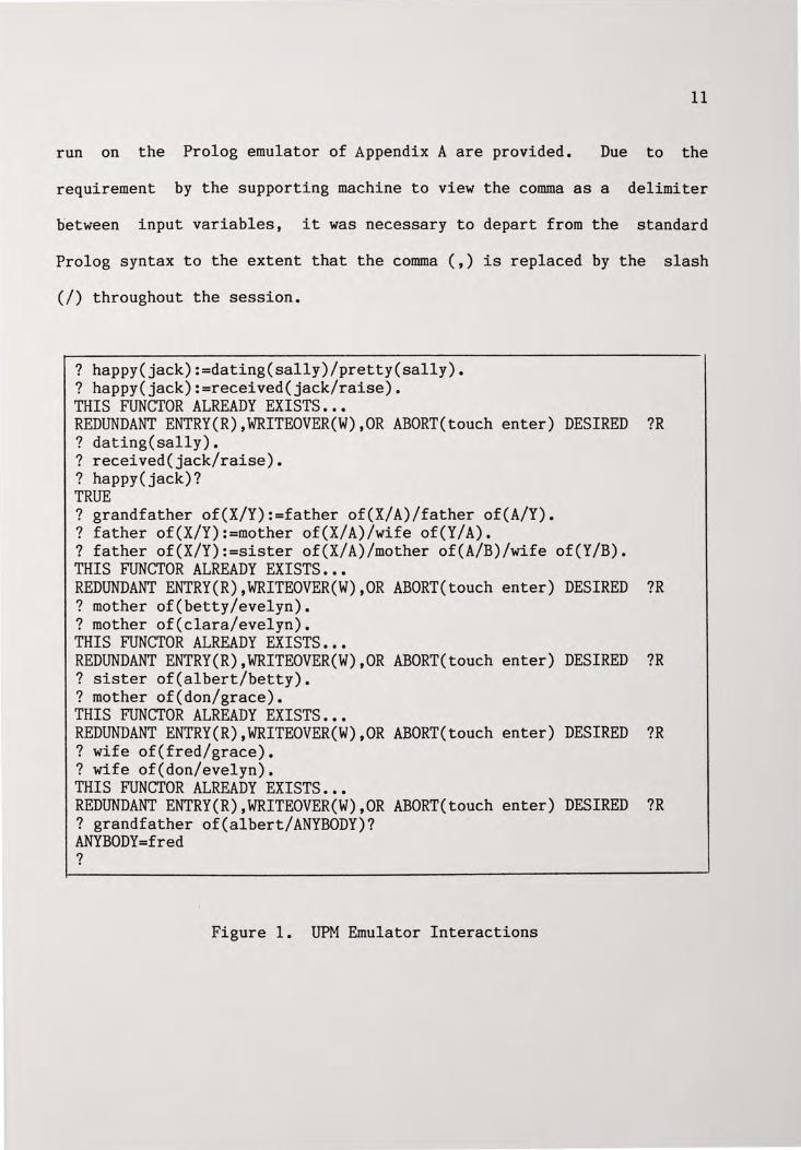
Sample Interactions with a Prolog Machine
To ensure a level of familiarity of Prolog sufficient to appreciate
the task of the inference engine(s) described, the following programs
11
run on the Prolog emulator of Appendix A are provided. Due to the
requirement by the supporting machine to view the comma as a delimiter
between input variables, it was necessary to depart from the standard
Prolog syntax to the extent that the comma (,) is replaced by the slash
(/) throughout the session.
? happy(jack):=dating(sally)/pretty(sally). ? happy(jack):=received(jack/raise). THIS FUNCTOR ALREADY EXISTS ••• REDUNDANT ENTRY(R),WRITEOVER(W),OR ABORT(touch enter) DESIRED ?R ? dating(sally). ? received(jack/raise). ? happy(jack)? TRUE ? grandfather of(X/Y):=father of(X/A)/father of(A/Y). ? father of(X/Y):=mother of(X/A)/wife of(Y/A). ? father of(X/Y):=sister of(X/A)/mother of(A/B)/wife of(Y/B). THIS FUNCTOR ALREADY EXISTS ••• REDUNDANT ENTRY(R),WRITEOVER(W),OR ABORT(touch enter) DESIRED ?R ? mother of(betty/evelyn). ? mother of(clara/evelyn). THIS FUNCTOR ALREADY EXISTS ••• REDUNDANT ENTRY(R),WRITEOVER(W),OR ABORT(touch enter) DESIRED ?R ? sister of(albert/betty). ? mother of(don/grace). THIS FUNCTOR ALREADY EXISTS ••• REDUNDANT ENTRY(R),WRITEOVER(W),OR ABORT(touch enter) DESIRED ?R ? wife of(fred/grace). ? wife of(don/evelyn). THIS FUNCTOR ALREADY EXISTS ••• REDUNDANT ENTRY(R),WRITEOVER(W),OR ABORT(touch enter) DESIRED ?R ? grandfather of(albert/ANYBODY)? ANYBODY=f red ?
Figure 1. UPM Emulator Interactions
V. INFERENCE ENGINE CONSIDERATIONS
Overview
As previously discussed, the methodology of solution generation is
heavily dependent on the environment. Some Prolog applications
currently in use include MYCIN (diagnoses infections), PROSPECTOR (aids
geologists in evaluating mineral sites), PUFF (analyzes pulmonary
function tests), SACON (provides engineers with advice on structural
analysis) and DRILLING ADVISOR (troubleshoots problems encountered when
drilling an oil well), to name only a few.
In setting design priorities for such expert systems, attention
must be given to ensuring that the strengths of the design are in
alignment with the heaviest demands placed on it by the application
environment. For example an expert system operating within the real-time
constraints afforded by a cruise missile guidance system must emphasize
speed of decision making and interaction with information ports. Most
often it is the inference engine which represents the critical component
in achieving desired performance goals.
What follows is a look at the PLM-1 (Aquarius) project being
undertaken at Berkeley{7}. It is provided as a point of comparison for
the significant goals to be achieved in the UPM design.
PLM-1
The PLM-1 is intended to handle concurrently both logic and numeric
applications as an attached processor. The execution environment for
12
13
for PLM-1, as stated by Patt and Despain{7} is "to determine how a very
large improvement in performance can be achieved in a machine
specialized to solve some very difficult problems .which are
characterized by intensive numerical calculations tightly coupled to
substantial symbolic manipulations." As such, it is designed to operate
over an expansive database, a feature which will contrast sharply with
the UPM.
The PLM-1 consists of three major modules: the Microengine, the
Prolog Engine, and the Prolog Machine Interface; the Microengine is
responsible for the control of its own state as well as the two other
modules{8}.
The memory space (resident in an NCR/32 system acting as a host) is
divided into two areas: the Code Space and the Data Space. The Code
Space contains PLM-1 instructions which oversee the microsequencer
actions needed to service the current Prolog query.
are divided into five classes:
The instructions
A) Gets - used to unify with the head of an invoked subgoal.
B) Puts - used to set up the argument registers prior to invoking
a subgoal.
C) Unifies - construct and unify structured data.
D) Control - guide sequencing between subgoals, invoke built-in
functions.
E) Indexing - select clauses, manage the choice point, and
implement cuts.
The Data Space contains 32 bit tagged words representing all data items
and state information for a running Prolog program. It is divided into
14
three areas:
A) Trail - keeps track of variable bindings which must be unbound
upon backtracking.
B) Stack - LIFO format containing processor state information to
be restored on backtracking.
C) Heap - used for storage of lists and structures.
A fourth region, the Push Down List (a scratchpad area used during
unifications) is maintained within the Prolog engine.
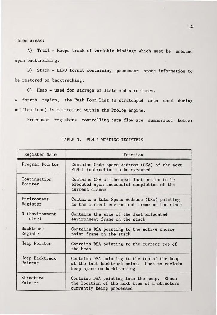
Processor registers controlling data flow are summarized below:
TABLE 3. PLM-1 WORKING REGISTERS
r
Register Name Function
Program Pointer Contains Code Space Address (CSA) of the next PLM-1 instruction to be executed
Continuation Contains CSA of the next instruction to be Pointer executed upon successful completion of the
current clause .
Environment Contains a Data Space Address (DSA) pointing Register to the current environment frame on the stack
N (Environment Contains the size of the last allocated size) environment frame on the stack
Backtrack Contains DSA pointing to the active choice Register point frame on the stack
Heap Pointer Contains DSA pointing to the current top of the heap
Heap Backtrack Contains DSA pointing to the top of the heap Pointer at the last backtrack point. Used to reclaim
heap space on backtracking
Structure Contains DSA pointing into the heap. Shows Pointer the location of the next item of a structure
currently being processed
15
The reader is encouraged to consult Despain and Patt{8} at this point
for additional insight into the microarchitecture and microengine of
PLM-1, as an appreciation of its major design features is an asset in
understanding the inference mechanisms of UPM.
UPM Design Criteria
The UPM is also intended to be an attached processor that will
augment the facilities of a microcomputer host machine. Consisting of
an I/O Sub Processor (handles communication with the host, and
interprets Prolog strings - analogous to the PMI of PLM-1), a Memory
Processor (provides interface with the main memory of the host, and
handles alignment of local and global variables during the unification
process), and a Central Processor Unit (CPU - microsequenced inference
engine which maintains stacks, pointers, and counters needed for program
execution), the UPM offers significant variations from the PLM-1 design
in the following aspects~
A) It is intended to work directly with Prolog strings as a source
code, via interpretation by the I/O Processor (as opposed to compiled
Prolog).
B) The target database size is smaller (typically 64-128k), and
is not divided into "Code Space" and "Data Space."
C) Built-in functions are not supported directly by the inference
engine, but are interpreted in input (and carried out) by the host when
necessary.
D) Due to the separation of the I/O, Memory, and Central Process
ors, a high degree of parallelism may be achieved. For example, the
16
database may be expanded during execution of a query via a direct memory
access path from the I/O processor to the Memory processor. Other
facilities for parallelism are expounded upon in the system description.
E) Forced microbranch operations (interrupts in a real-time
scenario) are not supported in the UPM, hence, next microaddress
selection logic is simplified. This design feature arises from the
assumption of a target system consisting of a stand-alone microcomputer.
F) Numeric processing is not provided. Numbers may be handled
"brute force" by interpreting as a string, though this method would be
inefficient.
G) Perhaps most significantly, all stacks which are maintained in
the host memory by PLM-1 (accesses are "traditional" in that only
pointers are maintained in the microengine, and read requests must be
issued to, and serviced by, the host), are actually hardware resident in
the UPM. Numerous stacks and pointers needed in the PLM-1 are
eliminated or combined in the UPM. Table 4 relates the processor -
registers of PLM-1 and their associated UPM equivalent, emphasizing the
overall reduction of maintenance pointers required. This scheme reduces
and in some cases eliminates the problems discussed by Patt and
Despain{8} reagarding a memory bottleneck when referencing the Code
Space of the host. By maintaining the Choice Point Stack, Environment
File, and the Goal Stack "in house" in the UPM, there is no requirement
to shadow the registers or to buffer memory accesses, since each region
is independently accessible. Wait states only occur when accessing the
host memory for a new clause. There are additional consequences arising
from this arrangement, to be addressed in the conclusions.
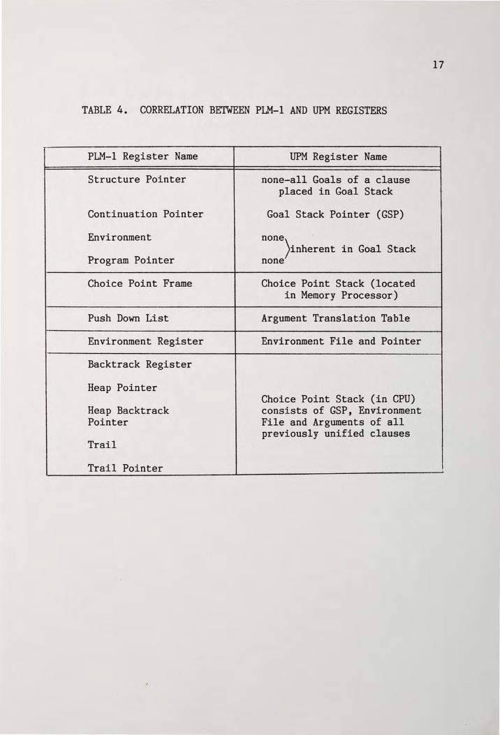
TABLE 4. CORRELATION BETWEEN PLM-1 AND UPM REGISTERS
PLM-1 Register Name
Structure Pointer
Continuation Pointer
Environment
Program Pointer
Choice Point Frame
Push Down List
Environment Register
Backtrack Register
Heap Pointer
Heap Backtrack Pointer
Trail
Trail Pointer
UPM Register Name
none-all Goals of a clause placed in Goal Stack
Goal Stack Pointer (GSP)
none · )inherent in Goal Stack
none
Choice Point Stack (located in Memory Processor)
Argument Translation Table
Environment File and Pointer
Choice Point Stack (in CPU) consists of GSP, Environment File and Arguments of all previously unified clauses
17
VI. UPM REALIZATION
The focus of the facilities realization portion of this writing
will be on the CPU, however, its role in conjunction with the entire
module will initially be addressed.
Description of Facilities
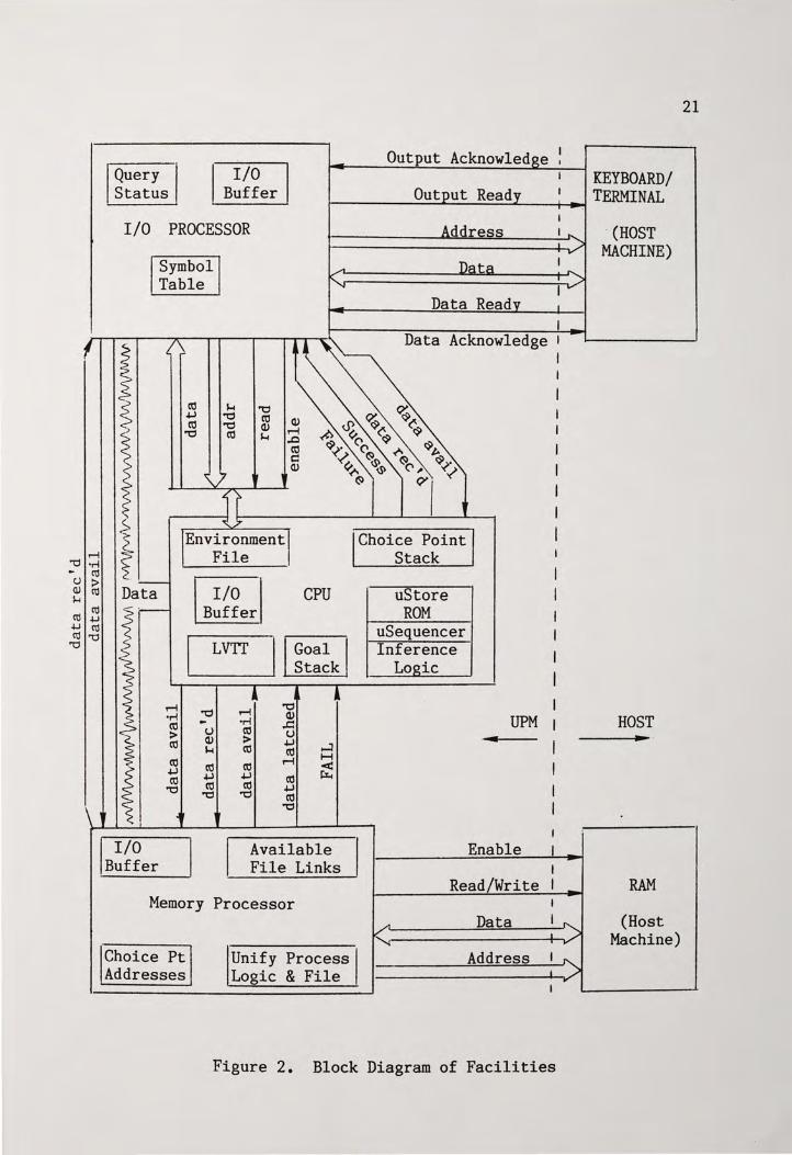
Figure 2 illustrates the major facilities of the UPM along with
interconnecting buswork and communication protocol (single bit) lines.
Memory Processor
The Memory Processor is presented via the I/O Buffer the goal at
the top of the goal stack and argument information consisting of either:
A) Bound variables, or
B) Argument file displacements (for unbound variables).
The rule and fact database is then searched in a top-to-bottom manner
for a rule or fact which will unify (i.e., has a matching head and does
not have conflicts for bound variables in the same argument position)
with the goal.
Three conditions may result, and the Unify Process Logic and File
will load the I/O Buffer accordi~gly:
A) Neither a rule nor fact is found. This causes the fail
condition to be transmitted to the CPU.
B) A fact will be found. The arity field is set to 0 and
transmitted arguments are all bound literals.
C) A rule will be found. New rules will be returned to the CPU
18
19
one at a time. The goal field will contain the symbol for the new rule
and the argument fields abide by the criteria of Table 6, page 30.
Finally, the Memory Processor has a resident Choice Point Stack
(LIFO) which holds addresses of previously successful searches. This
facilitates continuation of the top-down search strategy should
backtracking be necessary.
Input/Output Processor
The Input/Output Processor provides an interface between the
inference engine of the CPU and the host - it performs writing and
reading of data to and from a predetermined control word in the address
space of the the host.
It must perform bidirectional conversion between text strings of
arbitrary length and eight bit (binary) symbols used in the inference
process by the CPU - this association is achieved via a symbol table
whose address represents the symbol and whose contents are the text
string.
The I/O Processor also maintains a Query Status Table (QST) which
is always clear between queries. It holds the EF position (within the
CPU) of the arguments contained in the initial query along with a tag
bit indicating which arguments were input as literals, and which were
variables. In the event of successful goal satisfaction, the QST allows
the I/O Processor to perform a DMA to the EF and retrieve new bindings
for output to the user. Had the query been a True/False question (see
the first emulation result, page 11) the I/O Processor will realize this
by consulting (anding together) the tag bits of the QST.
20
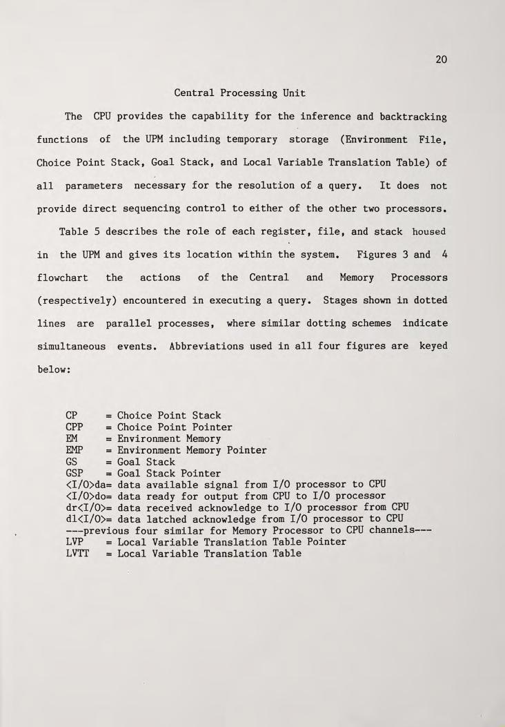
Central Processing Unit
The CPU provides the capability for the inference and backtracking
functions of the UPM including temporary storage (Environment File,
Choice Point Stack, Goal Stack, and Local Variable Translation Table) of
all parameters necessary for the resolution of a query. It does not
provide direct sequencing control to either of the other two processors.
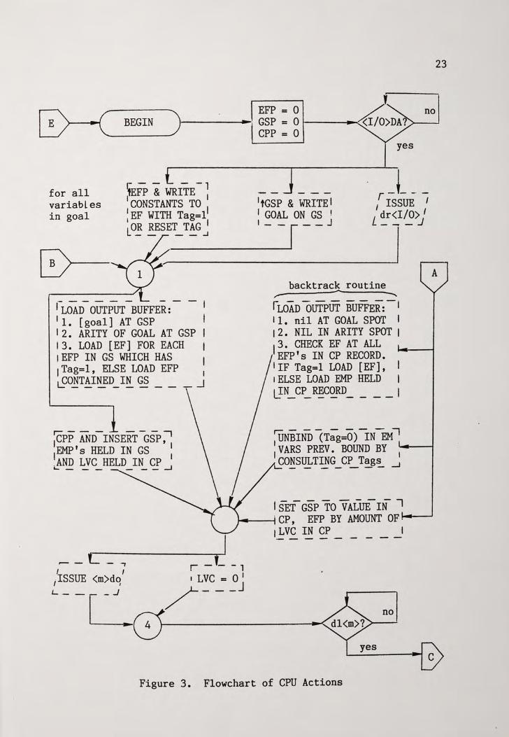
Table 5 describes the role of each register, file, and stack housed
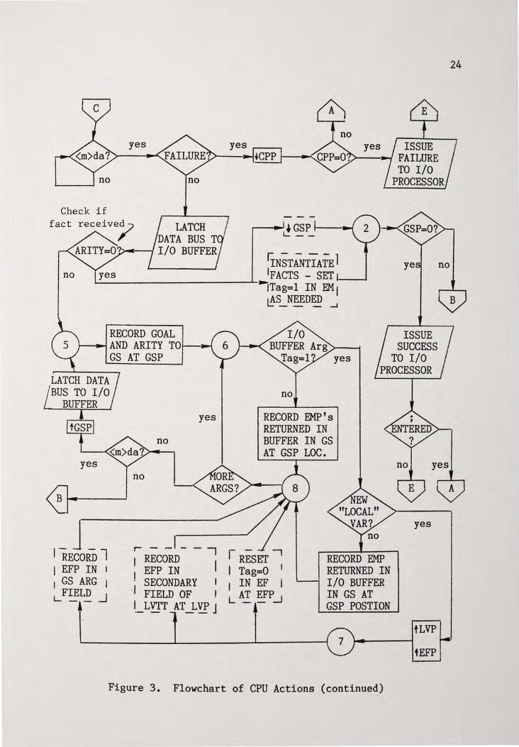
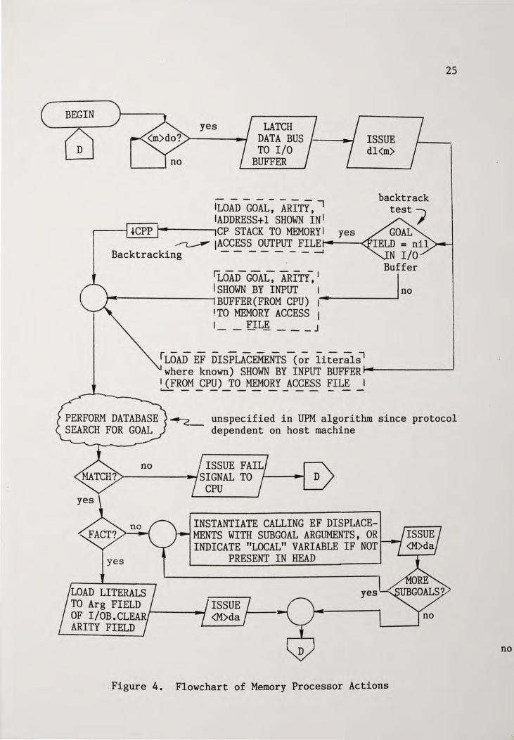
in the UPM and gives its location within the system. Figures 3 and 4
flowchart the actions of the Central and Memory Processors
(respectively) encountered in executing a query. Stages shown in dotted
lines are parallel processes, where similar dotting schemes indicate
simultaneous events. Abbreviations used in all four figures are keyed
below:
CP = Choice Point Stack CPP = Choice Point Pointer EM = Environment Memory EMP = Environment Memory Pointer GS = Goal Stack GSP = Goal Stack Pointer <I/O>da= data available signal from I/O processor to CPU <I/O>do= data ready for output from CPU to I/O processor dr<I/0>= data received acknowledge to I/O processor from CPU dl<I/0>= data latched acknowledge from I/O processor to CPU ---previous four similar for Memory Processor to CPU channels---LVP = Local Variable Translation Table Pointer LVTI' = Local Variable Translation Table
Query Status
I/O Buff er
I/O PROCESSOR
Symbol Table
ro +' ro
'O
$.-4 '"tj '"tj ro
'"tj ro Q) $.-4
Q) r-1 ..c ro d Q)
Environment File
Data I/O Buffer
LVTI
r-1 'O r-1 'O •M Q)
ro - ·M ..c:: > u ro u
Q) > +' ro $.-4 ro ro ro ro ro r-1 +' ro +' +' ro
'O ro ro +' 'O 'O ro
'O
CPU
....:I H < ~
Available File Links
Memory Processor
Choice Pt Unify Process Addresses Logic & File
Output Acknowled e ,
ddress
Data Read
Data Acknowledge
Choice Point Stack
uStore ROM
uSequencer Inference
Logic
UPM ...
Enable
Read/Write
Data
""' Address
Figure 2. Block Diagram of Facilities
· (HOST MACHINE)
HOST ... .
RAM
(Host Machine)
21
22
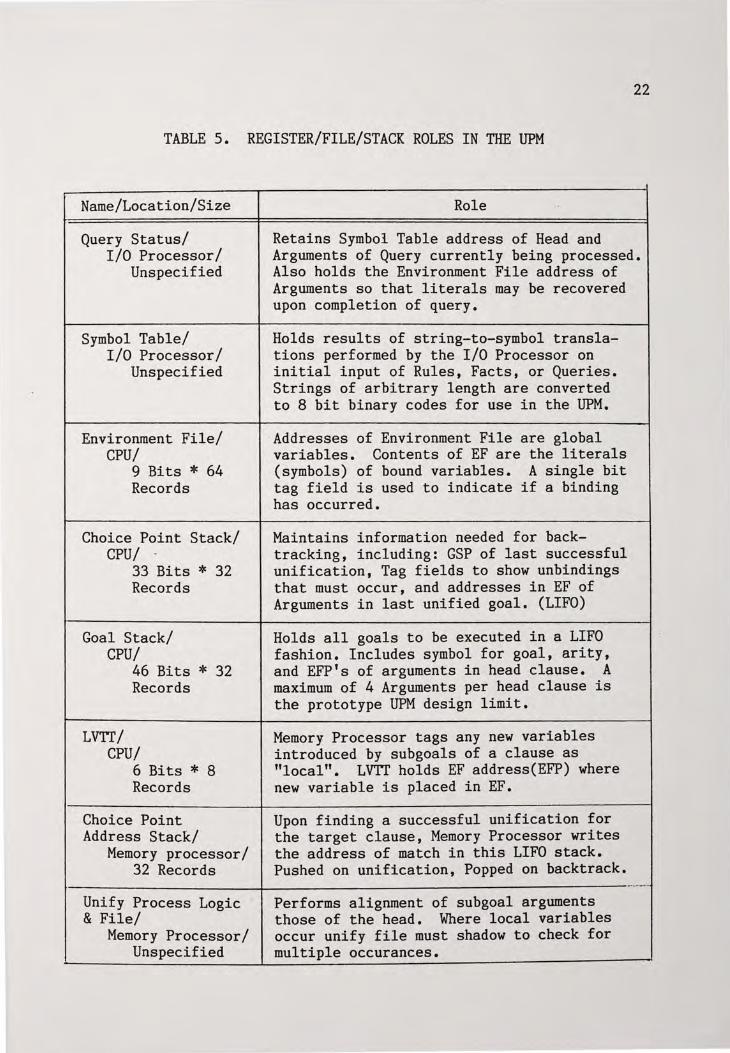
TABLE 5. REGISTER/FILE/STACK ROLES IN THE UPM
Name/Location/Size
Query Status/ I/O Processor/
Unspecified
Symbol Table/ I/O Processor/
Unspecified
Environment File/ CPU/
9 Bits * 64 Records
Choice Point Stack/ CPU/
33 Bits * 32 Records
Goal Stack/ CPU/
46 Bits * 32 Records
LVTI/ CPU/
6 Bits * 8 Records
Choice Point Address Stack/
Memory processor/ 32 Records
Role
Retains Symbol Table address of Head and Arguments of Query currently being processed. Also holds the Environment File address of Arguments so that literals may be recovered upon completion of query.
Holds results of string-to-symbol translations performed by the I/O Processor on initial input of Rules, Facts, or Queries. Strings of arbitrary length are converted to 8 bit binary codes for use in the UPM.
Addresses of Environment File are global variables. Contents of EF are the literals (symbols) of bound variables. A single bit tag field is used to indicate if a binding has occurred.
Maintains information needed for backtracking, including: GSP of last successful unification, Tag fields to show unbindings that must occur, and addresses in EF of Arguments in last unified goal. (LIFO)
Holds all goals to be executed in a LIFO fashion. Includes symbol for goal, arity, and EFP's of arguments in head clause. A maximum of 4 Arguments per head clause is the prototype UPM design limit.
Memory Processor tags any new variables introduced by subgoals of a clause as "local". LVTf holds EF address(EFP) where new variable is placed in EF.
Upon finding a successful unification for the target clause, Memory Processor writes the address of match in this LIFO stack. Pushed on unification, Popped on backtrack.
t------------'------------------------------Unify Process Logic & File/
Memory Processor/ Unspecified
Performs alignment of subgoal arguments those of the head. Where local variables occur unify file must shadow to check for multiple occurances.
23
EFP = 0 no BEGIN •----~: GSP = 0 i----~
CPP = 0 yes
ifEFP&WRITE-~ --- r_L __ : CONSTANTS TO I 1tGSP & WRITE I ISSUE I
for all variables in goal 1
EF WITH Tag=l 1 GOAL ON GS ! / dr<I/O> I
LO~ RES:_E--T---T~A-G~_J-l~~--~--~-'-=---=-=='-----J ___ l __ ____Jl- J.-----.
rLOAD- OUTPUT -BUFFER: - - I 11. [goal] AT GSP I 12. ARITY OF GOAL AT GSP I 13. LOAD [EF] FOR EACH I 1EFP IN GS WHICH HAS I 1Tag=l, ELSE LOAD EFP 1 ~DETAINED_ IN GS ___ _J
~PP AND-INSERT -GSP ;' EMP's HELD IN GS 1
~AND LVC HELD IN CP 1
1.... ______ _J
backtrack routine
rLoAD oUTPUT BUFFER:-, 11. nil AT GOAL SPOT I I 2 • NIL IN ARITY SPOT I 3. CHECK EF AT ALL
IEFP's IN CP RECORD. I IF Tag=l LOAD [EF], I 1 ELSE LOAD EMP HELD I llN_ C~ R~CORD _ _ __ I
~NBIND (Tag=O) IN-EM-, I VARS PREV. BOUND BY ,..
1 .._~
CO~SULTING _ C~ Tag~ _J
I SET-GSP TO VALUE-IN -, .,..__~· CP, EFP BY AMOUNT OF....._~
r _ f_ - 1
I LVC = 0 I / ___ J
l_~vc IN CP - ·- - - _I
no
Figure 3. Flowchart of CPU Actions
Check if
no
LATCH DATA BUS T
~-_, I/O BUFFER
RECORD GOAL
yes · ISSUE >---11-' FAILURE
TO I/O PROCESSOR
rrNsTAfrrIATE 1 !FACTS - SET .__...
~Tag=l IN EM I 0S_NEEDED ....J
--AND ARITY T01---..t ISSUE
SUCCESS TO I/O
PROCESSOR .LATCH DATA BUS TO I/O
BUFFER
yes
I_ J _ l RECORD
I EFP IN i I GS ARG I LFIELD _J -,-
GS AT GSP yes
no
yes
no
RECORD EMP's RETURNED IN BUFFER IN GS AT GSP LOC.
no
r - _I_ - I
1 REcoRD
1 r RESET--,
EFP IN I Tag=O 1
: SECONDARY I I IN EF I . FIELD OF I LAT EFP _J
l __ LVTT _AT~VP J
RECORD EMP RETURNED IN I/O BUFFER IN GS AT GSP POSTION
Figure 3. Flowchart of CPU Actions (continued)
yes
tLVP
iEFP
24
BEGIN yes LATCH
DATA BUS TO I/O
BUFFER
ILOAD GOAL~ ARITY' -, IADDRESS+l SHOWN INI
7/ ISSUE 1
___ d_l_<_m_>---'/
backtrack
-- ~CPP CP STACK TO MEMORY I ~ !ACCESS OUTPUT FILE.,__.--<
Backtracking - - - - - - - -4
~OAD-GOA~ ARITY~ I ISHOWN BY INPUT I
~----------1 BUFFER(FROM CPU) 1_,...,..._ ___ _.;i
ITO MEMORY ACCESS I I FILE _______ J
r---- ------ ----, LOAD EF DISPLACEMENTS (or literals
25
where known) SHOWN BY INPUT BUFFER.,__ _____ , l(FROM CPU) TO MEMORY ACCESS FILE I ~---------- ---
~ unspecified in UPM algorithm since protocol dependent on host machine
ISSUE FAIL >----~SIGNAL TO
yes
LOAD LITERALS
CPU
INSTANTIATE CALLING EF DISPLACEMENTS WITH SUBGOAL ARGUMENTS, OR INDICATE "LOCAL" VARIABLE IF NOT
PRESENT IN HEAD
yes TO Arg FIELD ISSUE OF I/OB. CLEAR t--------1~ <M>da 1--J~ ARITY FIELD
Figure 4. Flowchart of Memory Processor Actions
no
26
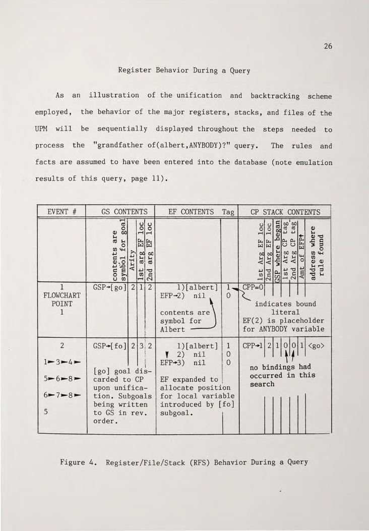
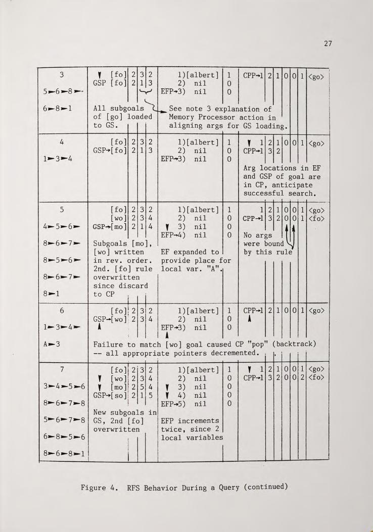
Register Behavior During a Query
As an illustration of the unification and backtracking scheme
employed, the behavior of the major registers, stacks, and files of the
UPM will be sequentially displayed throughout the steps needed to
process the "grandfather of(albert,ANYBODY)?" query. The rules and
facts are assumed to have been entered into the database (note emulation
results of this query, page 11).
EVENT # GS CONTENTS EF CONTENTS Tag CP STACK CONTENTS M c:: I .
tt1 u u CJ CJ m bO bO
0 0 0 0 0 m m Q) Q) 00 r-1 r-1 r""""1 r""""1 Q)
.µ .µ $..! $..! • Q) "C tt1 $..! ~ ~ ~ ~
.0 0.... 0.... 0.... ..c: c:: ~ 0 ~ ~ ~ ~ Q) uu ~
~ :::1 l1l 4-1
~ $..! 0
~
~~ oc bO bO bO l1l 4-1
c:: r-1 .µ
H H Q) H H 4-1 l1l
-M -§ << 0 Q) Q) Q)_Q H < <
~ ';.o < .µ $..! r-1 c:: s ~"C .µ ~ p... .µ ~
~ "C :::1
0 p..., l1l c:: Cl) i:: Cl) i:: "C $..! u l1l .-! N ...-! N ~ ...-!IN ro
1 GSP-.[go] 2 1 2 l)[albert] 1..,... re:P=O I FLOWCHART EFP-2) nil 0 POINT indicates bound
1 content~ literal symbol for EF(2) is placeholder
1:
Albert · for ANYBODY variable :1
CPP•ll2 ll\1~111 <go> 2 GSP-+[fo] 2 3 !; 2 1 )[albert] 1 ,,
' 2) nil 0 .:
1 ..... 3~4~ l EFP ..... 3) nil 0 [go] goal dis- no bindings had
s ..... 6 ..... 8 ..... carded to CP EF expanded to I occurred in this I search upon unif ica- allocate position
6~7 ..... g ..... tion. Subgoals for local variable being written introduced by [fo]
5 to GS in rev. subgoal. order.
Figure 4. Register/File/Stack (RFS) Behavior During a Query
3 ' [fo] 2 3 2 l)[albert] 1 CPP~l 2 1 O O 1 <go> GSP [fo] 2 1 3 2) nil 0
s~6~s~~ ~ EFP..,3) nil 0
4
5
6
All subgoals~~ See note 3 explanation of of [go] loaded Memory Processor action in to GS. aligning args for GS loading.
[ fo] 2 3 2 GSP~[fo] 2 1 3
[ fo] 2 3 2 [wo] 2 3 4
GSP~[mo] 2 1 4
Subgoals [mo], [wo] written in rev. order. 2nd. [fo] rule overwritten since discard to CP
I [ f 0] l 2 3 2
GSP-[ WO] : 2 3 4 A .
l)[albert] 2) nil
EFP...,3) nil
1 0 0
1 )[al bert] 1 2) nil 0
y 3) nil 0 EFP-4) nil 0
EF expanded to provide place for local var. "A".
1 )[al bert] 1 2) nil 0
EFP.,.3) nil 0 I A
Y 1 2 1 0 0 1 <go> CPP-1 3 2
Arg locations in EF and GSP of goal are in CP, anticipate successful search.
1 2 1 0 0 1 <go> CPP-+l 3 2 0 0 1 <f o)
No args t Ii were bound_\.!.) by this rule
CPP-1 2 1 0 0 1 <go> A
A .... 3 Failure to match [wo] goal caused CP "pop" (backtrack)
7
-- all appropriate pointers decremented. . 1
[fo] 12 · 3 2 ' (WO] i 2 3 4 Y [mo] r 2 5 4
GSP-)>[ so] l 2 1 5 I
l)[albert] 2) nil
Y 3) nil Y 4) ·nil
EFP--.S) nil New subgoals GS, 2nd [fo] overwritten
in1
j EFP increments · twice, since 2 I 1ocal variables
I I
1 0 0 0 0
Y 1 2 1 0 0 1 <go> CPP~l 3 2 0 0 2 <fo>
Figure 4. RFS Behavior During a Query (continued)
27
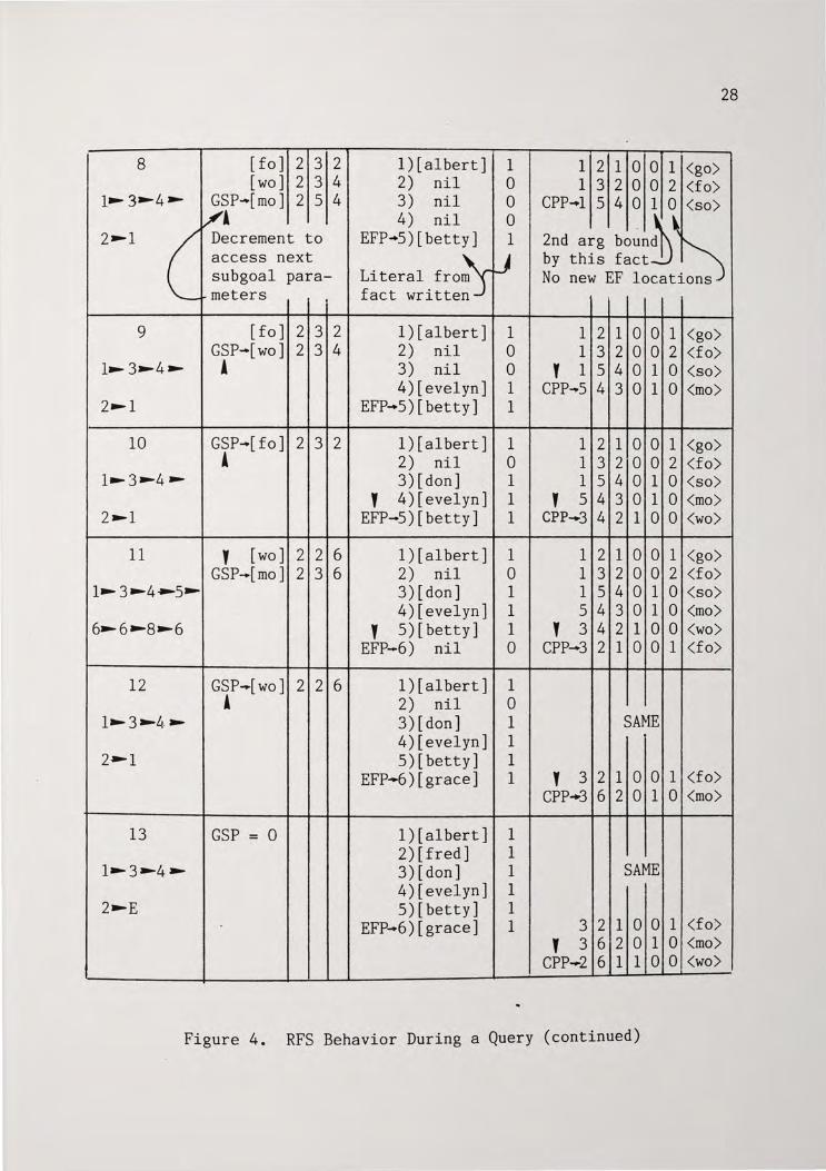
28
8 [fo] 2 3 2 l)[albert] 1 1 2 1 0 0 1 <go> [wo] 2 3 4 2) nil 0 1 3 2 0 0 2 <fo>
1~3~4,.. GSP-[mo] 2 5 4 3) nil 0 CPP-1 5 4 0 1 0 <so> /A 4) nil 0
. ~~ 2,..1 (_ Decrement to EFP-+5)[betty] 1 2nd arg bound ~ access next lJ by this fact subgoal para- Literal fro~ No new EF locations
'-meters . fact written
9 [fo] 2 3 2 l)[albert] 1 1 2 1 0 0 1 <go> GSP-[wo] 2 3 4 2) nil 0 1 3 2 0 0 2 <f o>
l~ 3,..4,.. A 3) nil 0 ' 1 5 4 0 1 0 <so> 4)[evelyn] 1 CPP-.5 4 3 0 1 0 <mo>
2~1 EFP-5)[betty] 1
10 GSP-[fo] 2 3 2 l)[albert] 1 1 2 1 0 0 1 <go> A 2) nil 0 1 3 2 0 0 2 <fo>
1~3,._4,.. 3)[don] 1 1 5 4 0 1 0 <so)
' 4 )[ evelyn] 1 ' 5 4 3 0 1 0 <mo> 2,..1 EFP-5)[betty] 1 CPP-3 4 2 1 0 0 <wo>
11 ' [wo] 2 2 6 l)[albert] 1 1 2 1 0 0 1 <go> GSP-[mo] 2 3 6 2) nil 0 1 3 2 0 0 2 <fo>
1~3~4~5,.. 3)[don] 1 1 5 4 0 1 0 <so> 4)[evelyn] 1 5 4 3 0 1 0 <mo>
6,..6,._8,..6
' 5 )[betty] 1 ' 3 4 2 1 0 0 <wo>
EFP-6) nil 0 CPP-3 2 1 0 0 1 <f o>
12 GSP-[ WO] 2 2 6 l)[albert] 1 A 2) nil 0
1~3~Li. ~ 3)[ don] 1 SAME 4)[evelyn] . 1
2~1 5 )[betty] 1 EFP-6)[grace] 1 ' 3 2 1 0 0 1 <f o>
CPP•3 6 2 0 1 0 <mo>
13 GSP = 0 1 )[albert] 1 2)[fred] 1
1~3~4,.. 3)[don] 1 SAME 4)[evelyn] 1
2~E 5)[ betty] 1 EFP-6)[grace] 1 3 2 1 0 0 1 <f o>
' 3 6 2 0 1 0 <mo> CPP--2 6 1 1 0 0 <wo>
Figure 4. RFS Behavior During a Query (continued)
29
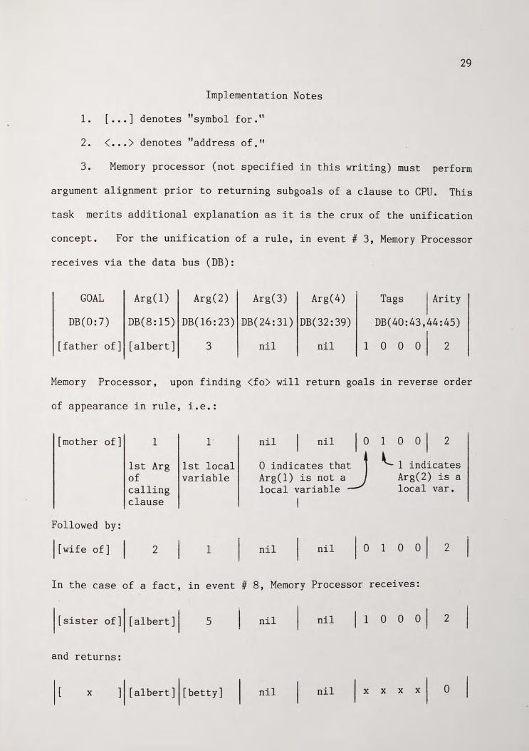
Implementation Notes
1. [ ••• ] denotes "symbol for."
2. < ••• >denotes "address of."
3. Memory processor (not specified in this writing) must perform
argument alignment prior to returning subgoals of a clause to CPU. This
task merits additional explanation as it is the crux of the unification
concept. For the unification of a rule, in event # 3, Memory Processor
receives via the data bus (DB):
GOAL Arg(l) Arg(2) Arg(3) Arg(4) Tags j Arity
DB(0:7) DB(8:15) DB(l6: 23) DB(24:31) DB(32:39) DB(40:43,44:45)
[father of] [albert] 3 nil nil 1 0 0 ol 2
Memory Processor, upon finding <fo) will return goals in reverse order
of appearance in rule, i.e.:
[mother of] 1
Followed by:
l[wifeof]
1st Arg of calling clause
2
1
1st local variable
1
nil nil I 0
0 indicates that . i Arg(l) is not a__) local variable
nil nil
1 o a I 2
l. 1 indicates Arg(2) is a local var.
In the case of a fact, in event # 8, Memory Processor receives:
![sister of]' [albert]I 5 nil nil j1 o o ol 2
and returns:
x ]I [albert]l[betty] nil nil I x x x x I o
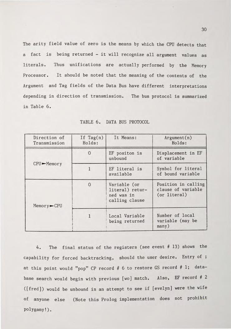
30
The arity field value of zero is the means by which the CPU detects that
a fact is being returned - it will recognize all argument values as
literals. Thus unifications are actually performed by · the Memory
Processor. It should be noted that the meaning of the contents of the
Argument and Tag fields of the Data Bus have different interpretations
depending in direction of transmission. The bus protocol is summarized
in Table 6.
TABLE 6. DATA BUS PROTOCOL
Direction of If Tag(n) It Means: Argument(n) Transmission Holds: Holds:
0 EF positon is Displacement in EF unbound of variable
CPU ..... Memory 1 EF literal is Symbol for literal
available of bound variable
0 Variable (or Position in calling literal) retur- clause of variable
I ned was in (or literal) I calling clause
! i Memory ..... CPU : i
! I I
Number of local 1 ~ Local Variable ! ! being returned variable (may be I many) I ' I
4. The final status of the registers (see event # 13) shows the
capability for _forced backtracking, should the user desire. Entry of ;
at this point would "pop" CP record # 6 to restore GS record # l; data-
base search would begin with previous [wo] match. Also, EF record # 2
([fred]) would be unbound in an attempt to see if [evelyn] were the wife
of anyone else (Note this Prolog implementation does not prohibit
polygamy!).
5. When GSP = 0, the "success" line to the I/O Controller
activated. The I/O Controller then executes a DMA to EF to access
31
is
new
bindings. By consulting the Query Status file, a determination can be
made regarding which EF postions need be accessed for output to the
user. Failure, had it occurred, would have been indicated by an empty CP
stack.
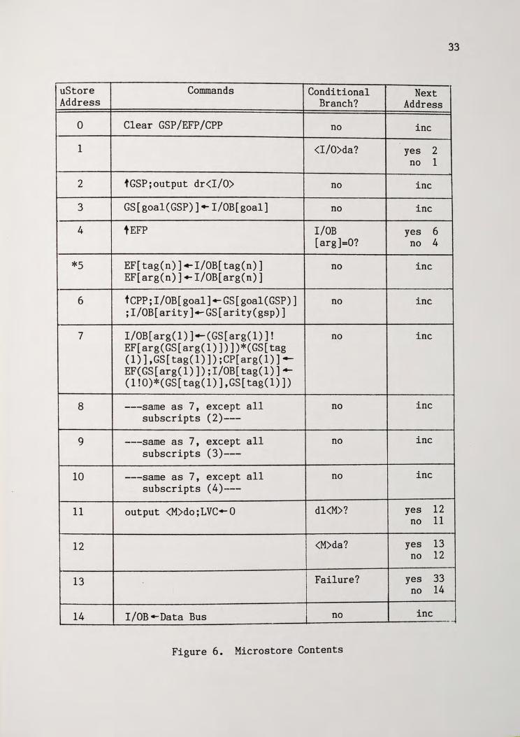
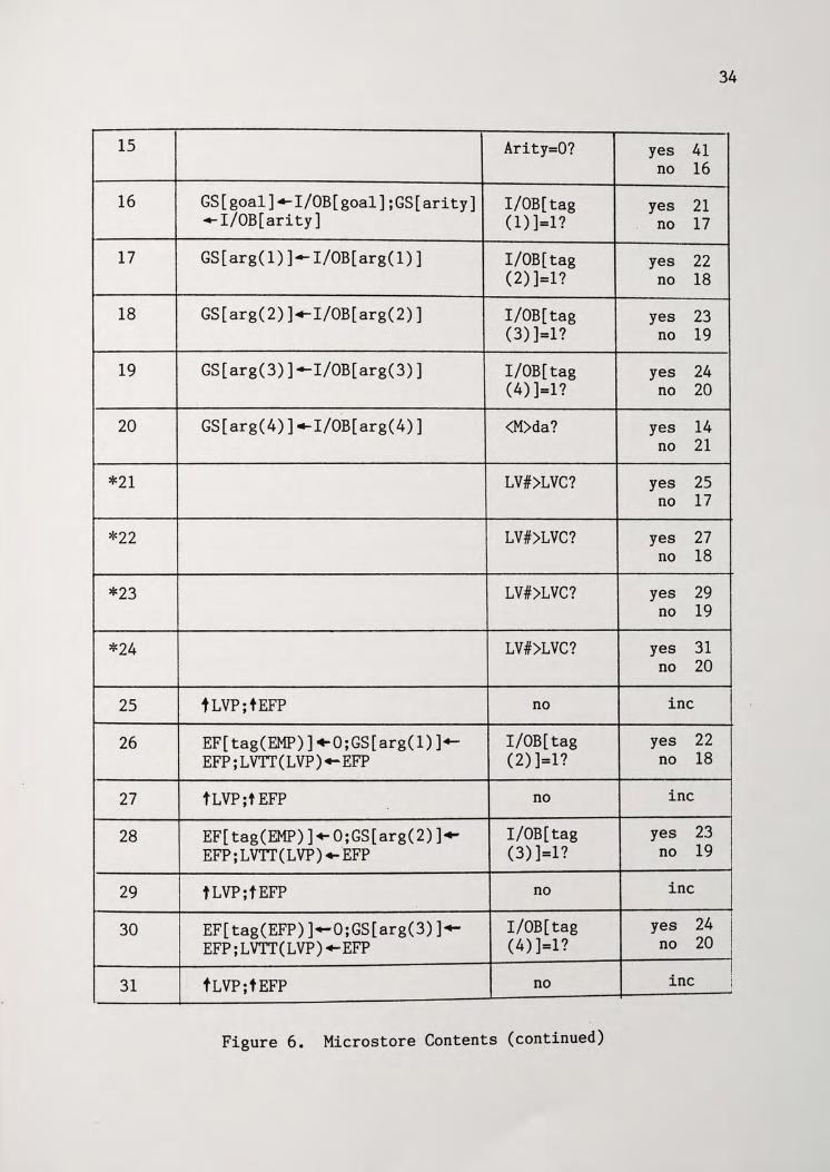
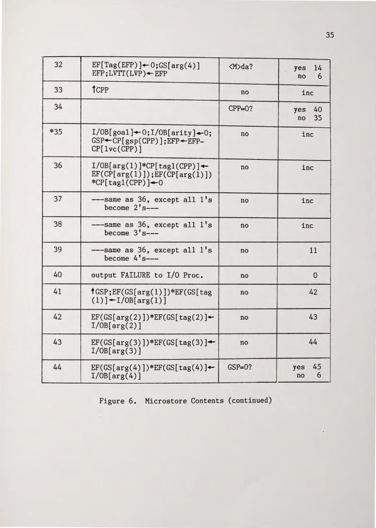
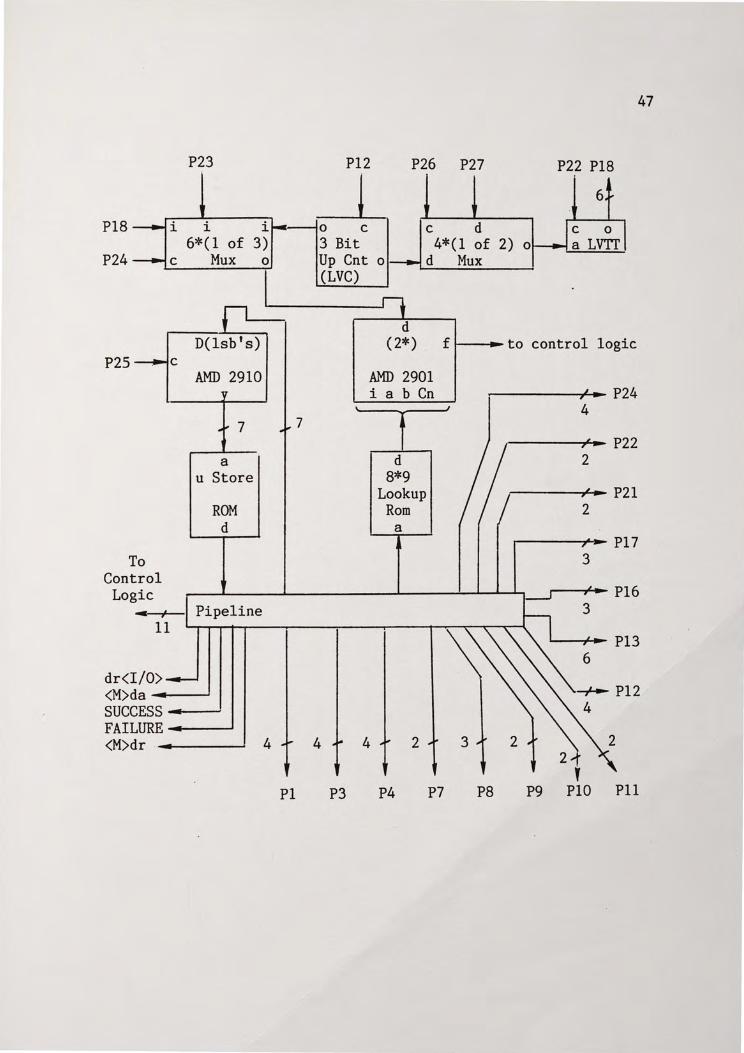
Proposed Microstore and Facilities
The microstore for the UPM is shown in pseudocode format in Figure
5, while a sketch of facilities is contained in Appendix B. The AMD
2910 is chosen as a target controller since its addressing capability is
within that required be the microstore of Figure 5. The alternative of
cascading AMD 2903s is also available, but needlelessly more
cumbersome.
As a result of the de-emphasis of mathematical operations in the
UPM, the need for an ALU is nearly obviated - the two uses of the AMD
2901 microprocessor slice is to compare the LVC to the Local Variable
Number returned by the memory processor to determine is a LVTT expansion
is in order, and to do the EMP decrement of step 35. A savings in
microstore width was achieved by installing a look-up ROM to supply the
limited (less than eight variations) number of ALU control bits to the
nine bit instruction field.
The needed control word width is seventy-nine bits, of which seven
are provided for direct input of non-incremental branch addresses. next
addresses. Multi-clock cycle subroutines are needed in the steps
annotated with an asterisk (those either implementing ALU functions, or
32
performing group transfers) - the subroutines are not specified in the
pseudocode.
Finally, some notes regarding the microstore content format:
1. "I/OB" throughout stands for Input/Output Buffer connected to
the external Data Bus.
2. The code conforms to AHPL conventions. For example, at address
3, the verbal interpretation would be "Perform a synchronous transfer of
the data contained in the [goal] field of the Input/Output Buffer to the
[goal] field of the goal stack pointed to by the goal stack pointer.
33
uStore Commands Conditional Next Address Branch? Address
0 Clear GSP/EFP/CPP no inc
1 <I/O>da? yes 2 no 1
2 tGSP;output dr<I/O> no inc
3 GS[goal(GSP)] .- I/OB[ goal] no inc
4 tEFP I/OB yes 6 [arg]=O? no 4
*S EF[tag(n)].-I/OB[tag(n)] no inc EF[arg(n)] +- I/OB[arg(n)]
6 tCPP;I/OB[goal]+-GS[goal(GSP)] no inc ;I/OB[arity]+-GS[arity(gsp)]
7 I/OB[arg(l)]~(GS[arg(l)]! no inc EF[arg(GS[arg(l)])])*(GS[tag (1)],GS[tag(l)]);CP[arg(l)] ..... EF(GS[arg(l)]);I/OB[tag(l)].,._ (l!O)*(GS[tag(l)],GS[tag(l)])
8 ---same as 7, except all no inc subscripts (2)---
9 ---same as 7, except all no inc subscripts (3)---
10 ---same as 7, except all no inc subscripts (4)---
11 output <M>do;LVC.-Q dl<M>? yes 12 no 11
12 <M>da? yes 13 no 12
13 Failure? yes 33 no 14
14 I/OB .. Data Bus no inc --
Figure 6. Microstore Contents
34
15 Arity=O? yes 41 no 16
16 GS[goal].,.I/OB[goal];GS[arity] I/OB[ tag yes 21 +-I/OB[arity] (1) ]=1? no 17
17 GS[arg(l)].,_I/OB[arg(l)] I/OB[ tag yes 22 (2)]=1? no 18
18 GS[arg(2)]+-I/OB[arg(2)] I/OB[ tag yes 23 (3)]=1? no 19
19 GS[arg(3)]._I/OB[arg(3)] I/OB[ tag yes 24 (4)]=1? no 20
20 GS[arg(4)]._I/OB[arg(4)] <M>da? yes 14 no 21
*21 LV#>LVC? yes 25 no 17
*22 LV#>LVC? yes 27 no 18
*23 LV#>LVC? yes 29 no 19
*24 LV#>LVC? yes 31 no 20
25 f LVP;tEFP no inc
26 EF[tag(EMP)]~O;GS[arg(l)]+- I/OB[ tag yes 22 EFP;LVTT(LVP).-EFP (2)]=1? no 18
27 tLVP;t EFP no inc
28 EF[ tag(EMP)] +-O;GS[arg(2) ] .. I/OB[tag yes 23 EFP; LVTT ( L VP) .., .EFP (3)]=1? no 19
29 tLVP;tEFP no inc
30 EF[tag(EFP)].-O;GS[arg(3)]+w I/OB[ tag yes 24 I EFP;LVTT(LVP)+.EFP (4)]=1? no 20
inc ! 31 fLVP;tEFP no j
Figure 6. Microstore Contents (continued)
35
32 EF[Tag(EFP)]~O;GS[arg(4)] <M>da? yes 14 EFP;LVTT(LVP)+-EFP no 6
33 1CPP no inc
34 CPP=O? yes 40 no 35
*35 I/OB[goal]+-O;I/OB[arity].-O; no inc GSP+-CP[gsp(CPP)];EFP~EFP-CP[lvc(CPP)]
36 I/OB[arg(l)]*CP[tagl(CPP)]~ no inc EF(CP[arg(l)]);EF(CP[arg(l)]) *CP[tagl(CPP)]---o
37 ---same as 36, except all l's no inc become 2's---
38 ---same as 36, except all l's no inc become 3's---
39 ---same as 36, except all l's no 11 become 4's---
40 output FAILURE to I/O Proc. no 0
41 fGSP;EF(GS[arg(l)])*EF(GS[tag no 42 (l)]--I/OB[arg(l)]
42 EF(GS[arg(2)])*EF(GS[tag(2)].- no 43 I/OB[arg(2)]
43 EF(GS[arg(3)])*EF(GS[tag(3)]._ no 44 I/OB[arg(3)]
44 EF(GS[arg(4)])*EF(GS[tag(4)]+- GSP=O? yes 45 I/OB[arg(4)] no 6
Figure 6. Microstore Contents (continued)
VII. CONCLUSIONS
Prolog has been determined by numerous artificial intelligence
research communities to be a language worthy of investigation, and this
report has touched on many of the points of discussion carried on by
these efforts. An attempts has been made to illustrate the relative
ease with which Prolog may be both implemented and exercised by an
individual intent on expeditiously interrogating the knowledge of a
small scale database.
Major differences between UPM and PLM-1 include:
1. Instruction and Data Types:
A. PLM-1:
instruction
instructions.
Queries are compiled from C-Prolog into an abstract Prolog
set which includes I/O, memory reference, and control
The traditional top-to-bottom, left-to-right execution/
search strategy associated with Prolog inference engines is controlled ·
by the compiled code.
B. UPM: Queries and program strings have the same form: encoded Prolog
strings. The data types used are similar to PLM-1, with the exception
of local variables. In the UPM, all variables are allotted a position
in the EF, thus "temporary" variables are never truly destroyed between
clauses, as in the PLM-1.
A trade-off is apparent in handling unbound arguments - less
maintenance is required (thus increased speed) by the UPM, however, the
EF capability may be exceeded in a program involving numerous local
variables.
36
37
2. Architecture:
A. PLM-1: A single microengine controls I/O, memory, and Prolog
inference tasks. With exception of the Push-Down List, the Data Space
internal to the PLM-1 consists only of pointers and indexes used in
addressing and tracking host memory space.
B. UPM: Three processors are specified, and major operations are
parceled out between the three. Especially significant is that the
unification function is combined with memory processing. The UPM
contains all inference information resident in dedicated RAM.
A speed increase for manipulation of overhead parameters (Choice
Points, Environment, Trail) can be expected in the UPM, due to reduction
of memory access traffic at the host interface bottleneck. The
consequence of having an invarient (hardware limited) ceiling on the
number of records available for tracking bindings, arguments, and choice
points might be intolerable on large scale systems anticipating a deep
level of backtracking, or numerous variables.
For the prototype UPM, the limits are as follows: (see Table 5)
256 symbols (8 bit argument fields) 32 levels of goal nesting per query 32 nodes retraceable on backtracking 64 total arguments per query 8 local variables per clause
These choices were arbitrary and made at an early stage of the design
process. Examination of the target operational environment might reveal
the need to vary these values. The advantage of a microsequenced system
is apparent should this action be required, since expansion is achieved
simply by adding memory and using additional microstore fields to carry
the extra addressing bits. Widening of the data bus argument fields is
necessary if more than 256 arguments are needed.

38
The basic emulation program of Appendix A serves to validate the
design, as well as provide a test base for further capability
examination, however, it falls short of yielding the necessary time
consumption parameters needed to document the speed improvement claimed
as a byproduct of the design. Further efforts should thus be centered
on building the hardware portion of the UPM specification, and
performing benchmark comparisons to verify its strengths and weaknesses.
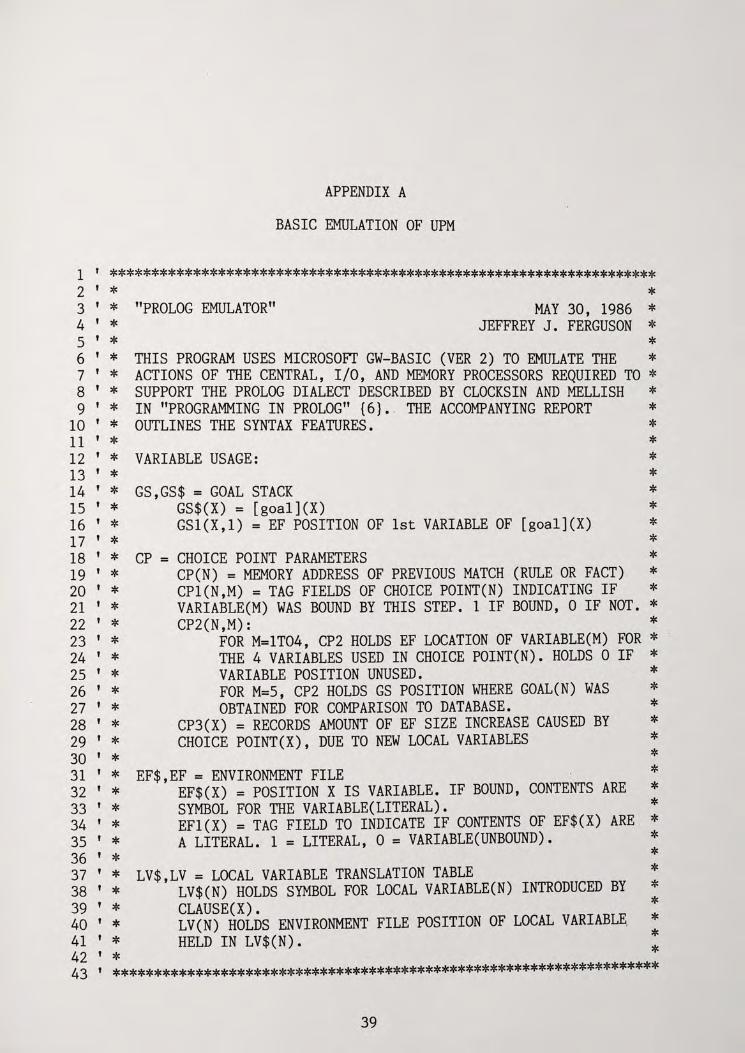
APPENDIX A
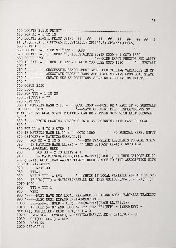
BASIC EMULATION OF UPM
1 ' ******************************************************************* 2 ' * * 3 ' * "PROLOG EMULATOR" MAY 30, 1986 * 4 ' * JEFFREY J. FERGUSON * 5 ' * * 6 ' * THIS PROGRAM USES MICROSOFT GW-BASIC (VER 2) TO EMULATE THE * 7 ' * ACTIONS OF THE CENTRAL, I/O, AND MEMORY PROCESSORS REQUIRED TO * 8 ' * SUPPORT THE PROLOG DIALECT DESCRIBED BY CLOCKSIN AND MELLISH * 9 ' * IN "PROGRAMMING IN PROLOG" {6) • . THE ACCOMPANYING REPORT *
10 ' * OUTLINES THE SYNTAX FEATURES. * 11 ' * * 12 ' * VARIABLE USAGE: * 13 ' * * 14 ' * GS,GS$ = GOAL STACK * 15 ' * GS$(X) = [goal ](X) * 16 ' * GSl(X,l) = EF POSITION OF 1st VARIABLE OF [goal](X) * 17 ' * * 18 ' * CP = CHOICE POINT PARAMETERS * 19 ' * CP(N) = MEMORY ADDRESS OF PREVIOUS MATCH (RULE OR FACT) * 20 ' * CPl(N,M) =TAG FIELDS OF CHOICE POINT(N) INDICATING IF * 21 ' * VARIABLE(M) WAS BOUND BY THIS STEP. 1 IF BOUND, 0 IF NOT. * 22 ' * CP2(N,M): * 23 ' * FOR M=lT04, CP2 HOLDS EF LOCATION OF VARIABLE(M) FOR * 24 ' * THE 4 VARIABLES USED IN CHOICE POINT(N). HOLDS 0 IF * 25 ' * VARIABLE POSITION UNUSED. * 26 ' * FOR M=5, CP2 HOLDS GS POSITION WHERE GOAL(N) WAS * 27 ' * OBTAINED FOR COMPARISON TO DATABASE. * 28 ' * CP3(X) = RECORDS AMOUNT OF EF SIZE INCREASE CAUSED BY * 29 ' * CHOICE POINT(X), DUE TO NEW LOCAL VARIABLES * 30 ' * * 31 ' * EF$,EF = ENVIRONMENT FILE * 32 ' * EF$(X) = POSITION X IS VARIABLE. IF BOUND, CONTENTS ARE * 33 ' * SYMBOL FOR THE VARIABLE(LITERAL). * 34 ' * EFl(X) = TAG FIELD TO INDICATE IF CONTENTS OF EF$(X) ARE * 35 ' * A LITERAL. 1 =LITERAL, 0 = VARIABLE(UNBOUND). * 36 ' * * 37 ' * LV$,LV = LOCAL VARIABLE TRANSLATION TABLE * 38 ' * LV$(N) HOLDS SYMBOL FOR LOCAL VARIABLE(N) INTRODUCED BY * 39 ' * CLAUSE(X). * 40 ' * LV(N) HOLDS ENVIRONMENT FILE POSITION OF LOCAL VARIABL~ * 41 ' * HELD IN LV$(N). ** 42 ' * 43 ' *******************************************************************
39
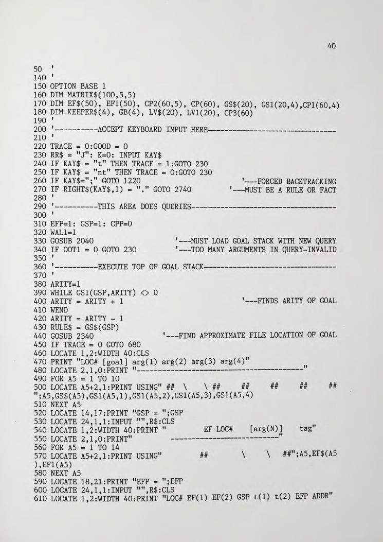
so ' 140 ' lSO OPTION BASE 1 160 DIM MATRIX$(100,S,S)
40
170 DIM EF$(SO), EFl(SO), CP2(60,S), CP(60), GS$(20), GS1(20,4),CP1(60,4) 180 DIM KEEPER$(4), GB(4), LV$(20), LV1(20), CP3(60) 190 ' 200 '----------ACCEPT KEYBOARD INPUT HERE-------------------------------210 ' 220 TRACE = O:GOOD = 0 230 RR$ = "J": K=O: INPUT KAY$ 240 IF KAY$ = "t" THEN TRACE= l:GOTO 230 2SO IF KAY$ = "nt" THEN TRACE = O:GOTO 230 260 IF KAY$=";" GOTO 1220 270 IF RIGHT$(KAY$,1) = "."GOTO 2740 280 '
'---FORCED BACKTRACKING '---MUST BE A RULE OR FACT
290 '----------THIS AREA DOES QUERIES-----------------------------------300 ' 310 EFP=l: GSP=l: CPP=O 320 WALl=l 330 GOSUB 2040 340 IF OOTl = 0 GOTO 230 3SO '
'---MUST LOAD GOAL STACK WITH NEW QUERY '---TOO MANY ARGUMENTS IN QUERY-INVALID
360 '----------EXECUTE TOP OF GOAL STACK--------------------------------370 ' 380 ARITY=l 390 WHILE GSl(GSP,ARITY) <> 0 400 ARITY = ARITY + 1 410 WEND 420 ARITY = ARITY - 1 430 RULE$ = GS$(GSP) 440 GOSUB 2340 4SO IF TRACE = 0 GOTO 680 460 LOCATE l,2:WIDTH 40:CLS
'---FINDS ARITY OF GOAL
'---FIND APPROXIMATE FILE LOCATION OF GOAL
470 PRINT "LOC# [goal] arg(l) arg(2) arg(3) arg(4)" 480 LOCATE 2,1,0:PRINT "----------------------------------------" 490 FOR AS = 1 TO 10 SOO LOCATE AS+2,l:PRINT USING" ## \ \ ## ## ";AS,GS$(AS),GSl(AS,1),GSl(AS,2),GSl(AS,3),GSl(AS,4) SlO NEXT AS S20 LOCATE 14,17:PRINT "GSP = ";GSP
##
S30 LOCATE 24,1,l:INPUT "",R$:CLS S40 LOCATE 1,2:WIDTH 40:PRINT " SSO LOCATE 2,1,0:PRINT"
EF LOC# [arg(N)] --------------------------
S60 FOR AS = 1 TO 14 S70 LOCATE AS+2,l:PRINT USING" ) ,EFl(AS) S80 NEXT AS S90 LOCATE 18,21:PRINT "EFP = ";EFP
## \ \
"
## ##
tag"
##";AS,EF$(AS
600 LOCATE 24,1,l:INPUT "",R$:CLS " 610 LOCATE 1,2:WIDTH 40:PRINT "LOC# EF(l) EF(2) GSP t(l) t(2) EFP ADDR
620 LOCATE 2,1,0:PRINT"----------------------------------------" 630 FOR AS = 1 TO 10
41
640 LOCATE AS+2,l:PRINT USING" ## ## ## ## ## ## ## ## # ##";AS,CP2(AS,1),CP2(AS,2),CP1(AS,1),CP1(AS,2),CP3(AS),CP(AS) 6SO NEXT AS 660 LOCATE 14,17:PRINT "CPP = ";CPP 670 LOCATE 24,1,l:INPUT "",R$:CLS:WIDTH 80:IF GOOD= 1 GOTO 1S80 680 GOSUB 2390 '---FIND EXACT FUNCTOR AND ARITY 690 IF FAIL = 1 THEN IF CPP = 0 GOTO 230 ELSE GOTO 1220 '---RESTART 700 ' 710 '----------SUCCESSFUL SEARCH-MUST STORE OLD CALLING VARIABLES IN CP 720 '----------ASSOCIATE "LOCAL" VARS WITH CALLING VARS FROM GOAL STACK 730 '----------CREATE NEW EF POSITIONS WHERE NO ASSOCIATION EXISTS 740 ' 7SO GOSUB 2SSO 760 LVC=O 770 FOR TTT = 1 TO 20 780 LV$(TTT) = "" 790 NEXT TTT 800 IF MATRIX$(HASH,2,l) = '"' GOTO 13SO'---MUST BE A FACT IF NO SUBGOALS 810 GOSUB 2670 '---SAVE ARGUMENT FILE DISPLACEMENTS SO THAT PRESENT GOAL STACK POSITION CAN BE WRITTEN OVER WITH LAST SUBGOAL 820 ' 830 '-----BEGIN LOADING SUBGOALS INTO GS BEGINNING WITH LAST SUBGOAL 840 ' 8SO FOR LL = S TO 2 STEP -1 860 IF MATRIX$(HASH,LL,l) = "" GOTO 1060 '---NO SUBGOAL HERE, EMPTY 870 GS$(GSP) = MATRIX$(HASH,LL,1) 880 FOR KK = 2 TO S '---NOW TRANSLATE ARGUMENTS TO GOAL STACK 890 IF MATRIX$(HASH,LL,KK) = "" THEN GSl(GSP,KK-l)=O:GOTO 1040
'---NO ARGUMENT HERE 900 FOR JJ = 2 TO ARITY + 1 910 IF MATRIX$(HASH,LL,KK) = MATRIX$(HASH,l,JJ) THEN GSl(GSP,KK-1) = GB(JJ-1): GOTO 1040'--SCAN TARGET HEAD CLAUSE TO FIND ASSOCIATION WITH SUBGOAL VARIABLES 920 NEXT JJ 930 TTT=l 940 WHILE TTT <= LVC '---CHECK IF LOCAL VARIABLE ALREADY EXISTS 9SO IF LV$(TTT) = MATRIX$(HASH,LL,KK) THEN GSl(GSP,KK-1) = LVl(TTT): GOTO 1040 960 TTT = TTT+l 970 WEND 980 '-----MUST HAVE NEW LOCAL VARIABLE~SO EXPAND LOCAL VARIABLE TRACKING 990 '-----ALSO MUST EXPAND ENVIRONMENT FILE 1000 EFP=EFP+l: HOLD= ASC(LEFT$(MATRIX$(HASH,LL,KK),l)) 1010 IF HOLD >= 97 AND HOLD <= 122 THEN EFl(EFP) = l:EF$(EFP) = MATRIX$(HASH,LL,KK) ELSE EFl(EFP) = 0 1020 LVC=LVC+l: LV$(LVC) = MATRIX$(HASH,LL,KK): LVl(LVC) = EFP 1030 GSl(GSP,KK-1) = EFP 1040 NEXT KK lOSO GSP=GSP+l

1060 NEXT LL 1070 GSP=GSP-1 1080 CP3(CPP) = LVC
42
1090 GOTO 380 '---THIS GOAL COMPLETE - CYCLE BACK FOR NEXT GOAL 1100 ' 1110 '-~-------ARGUMENT FILE LOADING SUBROUTINE--------------~----------1120 ' 1130 TEST$ = MID$(KAY$,VAL1+1,VAL2-VAL1-1) 1140 X$ = LEFT$(TEST$,1) 1150 IF ASC(X$) >= 97 AND ASC(X$) <= 122 THEN EF$(TT)=TEST$: EFl(TT)=l: ELSE EFl(TT)=O 1160 KEEPER$(TT) = TEST$ 1170 RETURN 1180 ' 1190 '----------RESTART IS ACCESSED AFTER FAILED SEARCHES FOR A FUNCTOR 1200 '----------"POP" CHOICE POINT TO DETERMINE SEARCH POINT 1210 ' 1220 GSP = CP2(CPP,5) '---REWRITE GOAL STACK FROM LAST MATCH 1230 GS$(GSP) = MATRIX$(CP(CPP),1,l) '---NOW HAVE PREVIOUS FUNCTOR 1240 FOR LL = 1 TO 4 1250 GSl(GSP,LL) = CP2(CPP,LL) '---PLACE AF LOCATIONS IN GOAL STACK 1260 IF CPl(CPP,LL)=l THEN EFl(CP2(CPP,LL))=O '---UNBIND ARGS IF NEEDED 1270 NEXT LL 1280 HASH = CP(CPP) + 1 1290 EFP = EFP -CP3(CPP) 1300 CPP = CPP - 1 1310 GOTO 450 '---BACKTRACK WITH THIS 1320 ' 1330 '----THIS PORTION INSTANTIATES FACTS WITH THEIR RESPECTIVE EF LOCS 1340 ' 1350 FOR LL = 1 TO 4 1360 HOLD(LL) = 0 1370 NEXT LL 1380 FOR LL = 1 TO 4 1390 TT= GSl(GSP,LL): IF TT= 0 THEN CPl(CPP,LL)=O: GOTO 1510 '---DONE 1400 TEST$ = MATRIX$(HASH,l,LL+l) 1410 X$ = LEFf$(TEST$,l) 1420 IF ASC(X$) <= 96 OR ASC(X$) >= 123 THEN CPl(CPP,LL)=O: GOTO 1510 1430 IF EFl(TT) = 0 THEN EF$(TT) = TEST$: EFl(TT)=l: CPl(CPP,LL)=l:HOLD (LL) = TT:GOTO 1510 1440 IF TEST$ = EF$(TT) THEN CPl(CPP,LL)=O: GOTO 1510 1450 FAIL = 0: GOSUB 2420: CPP=CPP-1 1460 FOR LL = 1 TO 4 1470 IF HOLD(LL) <> 0 THEN EFl(HOLD(LL)) = 0 1480 NEXT LL 1490 GOTO 690 1500 '-----CHECKED FOR SMALL CHARACTER - BIND IF IT IS 1510 NEXT LL 1520 GSP = GSP - 1 1530 IF GSP <> O GOTO 380 '---DO NEXT GOAL ON GOAL STACK 1540 '
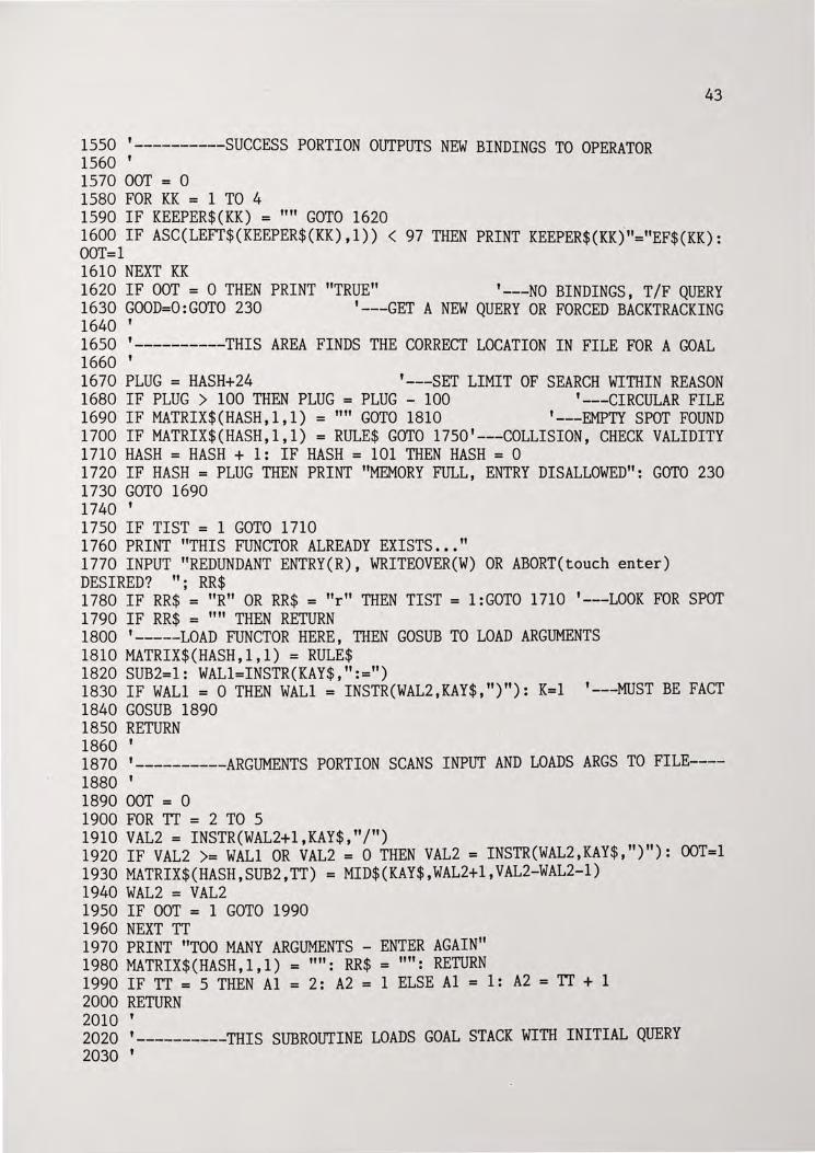
1550 '----------SUCCESS PORTION OUTPUTS NEW BINDINGS TO OPERATOR 1560 ' 1570 OOT = 0 1580 FOR KK = 1 TO 4 1590 IF KEEPER$(KK) = "" GOTO 1620
43
1600 IF ASC(LEFT$(KEEPER$(KK), 1)) < 97 THEN PRINT KEEPER$(KK)."="EF$(KK): OOT=l 1610 NEXT KK 1620 IF OOT = 0 THEN PRINT "TRUE" '---NO BINDINGS, T/F QUERY 1630 GOOD=O:GOTO 230 '---GET A NEW QUERY OR FORCED BACKTRACKING 1640 ' 1650 '----------THIS AREA FINDS THE CORRECT LOCATION IN FILE FOR A GOAL 1660 ' 1670 PLUG = HASH+24 '---SET LIMIT OF SEARCH WITHIN REASON 1680 IF PLUG > 100 THEN PLUG = PLUG - 100 '---CIRCULAR FILE 1690 IF MATRIX$(HASH,1,1) = "'' GOTO 1810 '---EMPTY SPOT FOUND 1700 IF MATRIX$(HASH,1,1) = RULE$ GOTO 1750'---COLLISION, CHECK VALIDITY 1710 HASH = HASH + 1: IF HASH = 101 THEN HASH= 0 1720 IF HASH = PLUG THEN PRINT "MEMORY FULL, ENTRY DISALLOWED": GOTO 230 1730 GOTO 1690 1740 ' 1750 IF TIST = 1 GOTO 1710 1760 PRINT "THIS FUNCTOR ALREADY EXISTS ••• " 1770 INPUT "REDUNDANT ENTRY(R), WRITEOVER(W) OR ABORT(touch enter) DESIRED? "; RR$ 1780 IF RR$ = "R" OR RR$ = "r" THEN TIST = l:GOTO 1710 '---LOOK FOR SPOT 1790 IF RR$ = "" THEN RETURN 1800 '-----LOAD FUNCTOR HERE, THEN GOSUB TO LOAD ARGUMENTS 1810 MATRIX$(HASH,l,l) = RULE$ 1820 SUB2=1: WALl=INSTR(KAY$,":=") 1830 IF WALl = 0 THEN WALl = INSTR(WAL2,KAY$, ")"): K=l '---MUST BE FACT . 1840 GOSUB 1890 1850 RETURN 1860 ' 1870 '----------ARGUMENTS PORTION SCANS INPUT AND LOADS ARGS TO FILE----1880 ' 1890 OOT = 0 1900 FOR TT = 2 TO 5 1910 VAL2 = INSTR(WAL2+1,KAY$,"/") 1920 IF VAL2 >= WALl OR VAL2 = 0 THEN VAL2 = INSTR(WAL2,KAY$,")"): OOT=l 1930 MATRIX$(HASH,SUB2,TT) = MID$(KAY$,WAL2+1,VAL2-WAL2-l) 1940 WAL2 = VAL2 1950 IF OOT = 1 GOTO 1990 1960 NEXT TT 1970 PRINT "TOO MANY ARGUMENTS - ENTER AGAIN" 1980 MA TRIX$ (HASH, 1 , 1 ) = "" : RR$ = '"' : RETURN 1990 IF TT= 5 THEN Al = 2: A2 = 1 ELSE Al = 1: A2 =Tr+ 1 2000 RETURN 2010 ' 2020 '----------THIS SUBROUTINE LOADS GOAL STACK WITH INITIAL QUERY 2030 '
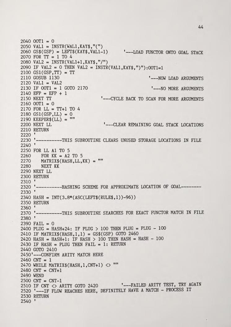
44
2040 OOTl = 0 2050 VALl = INSTR(WAL1,KAY$,"(") 2060 GS$(GSP) = LEFf$(KAY$,VAL1-1) '---LOAD FUNCTOR ONTO GOAL STACK 2070 FOR TT = 1 TO 4 2080 VAL2 = INSTR(VAL1+1,KAY$,"/") 2090 IF VAL2 = 0 THEN VAL2 = INSTR(VAL1,KAY$,")"):OOT1=1 2100 GSl(GSP,TT) = TT 2110 GOSUB 1130 '---NOW LOAD ARGUMENTS 2120 VALl = VAL2 2130 IF OOTl = 1 GOTO 2170 '---NO MORE ARGUMENTS 2140 EFP = EFP + 1 2150 NEXT TT '---CYCLE BACK TO SCAN FOR MORE ARGUMENTS 2160 OOTl = 0 2170 FOR LL = TT+l TO 4 2180 GSl(GSP,LL) = 0 2190 KEEPER$ (LL). = "" 2200 NEXT LL '---CLEAR REMAINING GOAL STACK LOCATIONS 2210 RETURN 2220 ' 2230 '----------THIS SUBROUTINE CLEARS UNUSED STORAGE LOCATIONS IN FILE 2240 ' 2250 FOR LL Al TO 5 2260 FOR KK = A2 TO 5 2270 MATRIX$(HASH,LL,KK) = "" 2280 NEXT KK 2290 NEXT LL 2300 RETURN 2310 ' 2320 '----------HASHING SCHEME FOR APPROXIMATE LOCATION OF GOAL--------2330 ' 2340 HASH = INT(3.8*(ASC(LEFf$(RULE$,1))-96)) 2350 RETURN 2360 ' 2370 '----------THIS SUBROUTINE SEARCHES FOR EXACT FUNCTOR MATCH IN FILE 2380 ' 2390 FAIL = 0 2400 PLUG = HASH+24: IF PLUG > 100 THEN PLUG = PLUG - 100 2410 IF MATRIX$(HASH,1,1) = GS$(GSP) GOTO 2460 2420 HASH = HASH+l: IF HASH > 100 THEN HASH = HASH - 100 2430 IF HASH = PLUG THEN FAIL = 1: RETURN 2440 GOTO 2410 2450'---CONFIRM ARITY MATCH HERE 2460 CNT = 1 2470 WHILE MATRIX$(HASH,1,CNT+l) <> '"' 2480 CNT = CNT+l 2490 WEND 2500 CNT = CNT-1 2510 IF CNT <> ARITY GOTO 2420 '---FAILED ARITY TEST, TRY AGAIN 2520 '---IF FLOW REACHES HERE, DEFINITELY HAVE A MATCH - PROCESS IT 2530 RETURN 2540 '
45
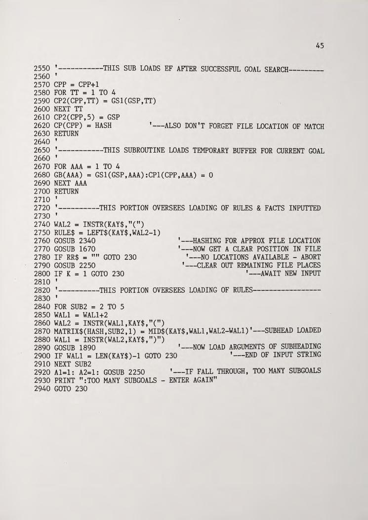
2550 '-----------THIS SUB LOADS EF AFI'ER SUCCESSFUL GOAL SEARCH---------2560 ' 2570 CPP = CPP+l 2580 FOR TT = 1 TO 4 2590 CP2(CPP,TT) = GSl(GSP,TT) 2600 NEXT TT 2610 CP2(CPP,5) = GSP 2620 CP(CPP) = HASH 2630 RETURN 2640 '
'---ALSO DON'T FORGET FILE LOCATION OF MATCH
2650 '-----------THIS SUBROUTINE LOADS TEMPORARY BUFFER FOR CURRENT GOAL 2660 ' . 2670 FOR AAA = 1 TO 4 2680 GB(AAA) = GSl(GSP,AAA):CPl(CPP,AAA) = 0 2690 NEXT AAA 2700 RETURN 2710 ' 2720 '----------THIS PORTION OVERSEES LOADING OF RULES & FACTS INPUTTED 2730 ' 2740 WAL2 = INSTR(KAY$,"(") 2750 RULE$ = LEFr$(KAY$,WAL2-l) 2760 GOSUB 2340 2770 GOSUB 1670 2780 IF RR$ = "" GOTO 230 2790 GOSUB 2250 2800 IF K = 1 GOTO 230 2810 '
'---HASHING FOR APPROX FILE LOCATION '---NOW GET A CLEAR POSITION IN FILE
'---NO LOCATIONS AVAILABLE - ABORT '---CLEAR OUT REMAINING FILE PLACES
'---AWAIT NEW INPUT
2820 '----------THIS PORTION OVERSEES LOADING OF RULES-----------------2830 ' 2840 FOR SUB2 = 2 TO 5 2850 WALl = WAL1+2 2860 WAL2 = INSTR(WAL1,KAY$,"(") 2870 MATRIX$(HASH,SUB2,l) = MID$(KAY$,WAL1,WAL2-WAL1)'---SUBHEAD LOADED 2880 WALl = INSTR(WAL2,KAY$,")") 2890 GOSUB 1890 '---NOW LOAD ARGUMENTS OF SUBHEADING 2900 IF WALl = LEN(KAY$)-l GOTO 230 '---END OF INPUT STRING 2910 NEXT SUB2 2920 Al=l: A2=1: GOSUB 2250 '---IF FALL THROUGH, TOO MANY SUBGOALS 2930 PRINT ":TOO MANY SUBGOALS - ENTER AGAIN" 2940 GOTO 230
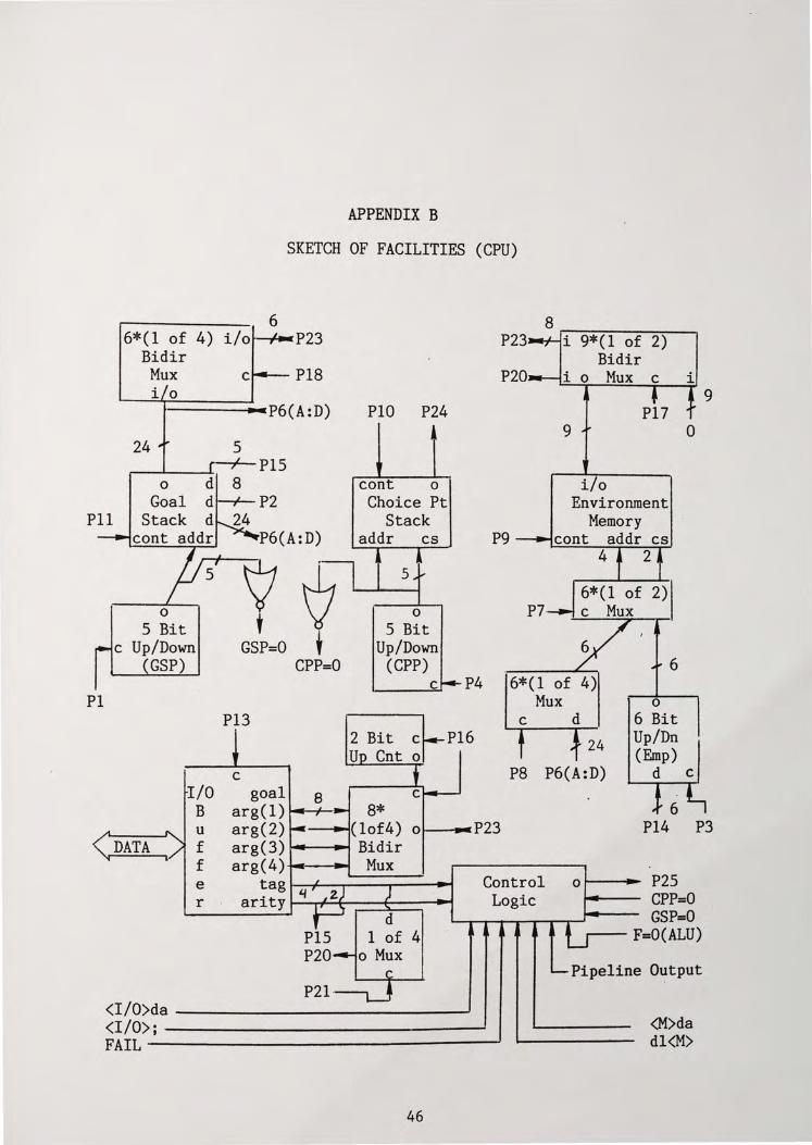
APPENDIX B
SKETCH OF FACILITIES (CPU)
6 6*(1 of 4) i/o P23
Bidir Mux Pl8 i 0
t-------•--•P6 (A: D)
24 s -+-PIS r-_._ _ __._,
0 d 8 Goal d P2
Pll Stack d 24
Pl
cont addr P6(A:D)
0
S Bit . c Up/Down
GSP)
\7 . t '7
GSP=O t CPP=O
Pl3
c I/O goal e
PIO P24
• cont o Choice Pt
Stack addr cs
5
0
S Bit Up/Down
(CPP) c
B arg(l) 8*
P4
8 .------P23 i 9*(1 of 2) Bidir
P20 i o Mux c i
P9
9
i/o
P7
24
PB P6(A:D)
6
0
6 Bit Up/Dn (Emp)
0
d c
9
u arg(2) .,.. _ __._.(lof4) o.,_--p23 P3 f arg(3) Bidir f arg(4) Mux e tag 'I r ari ty ~....J.;;;;;...__..__ _ __..
PIS P20
P21 ·
1 o Mux
Control Logic
<I/O>da ------------<I/O>; ~-----------------FAIL~---------------------
46
01-----11- P2S CPP=O GSP=O
F=O(ALU)
Pipeline Output
<M>da dl<M>
P18 i
P24 c
P25
P23
i i 6*(1 of 3)
Mux
D(lsb's)
AMD 2910
7
a u Store
ROM d
0
7
P12 P26 P27 P22 Pl8
6
0 c c d c 0
3 Bit 4*(1 of 2) o a LV'IT Up Cnt o d (LVC)
AMD 2901 i a b Cn
f d
8*9 Lookup
Rom a
Mux
f --to control logic
,...----~~P24
4
,-------ii;M' ... ~ P22 2
.---~,~, .,~ P21 2
r---~~ P17
47
To 3 Control
Logic .... r Pipeline
11
dr<I/O> <M>da ~-__, SUCCESS ---FAILURE ----___.. <M>dr - ~------ 4
Pl
4 4 2
P3 P4 P7 PB pg Pll
LIST OF REFERENCES
{l} Lemmons, Phil."Japan and the Fifth Generation." Byte, November 1983, pp. 394-401.
{2} Hayes-Roth, Fredrick "The Knowledge-Based Expert System: A Tutorial," IEEE Computer Society (September 1984):11-28.
{3} D'Ambrosio, Bruce "Expert Systems-Myth or Reality?" Byte, January 1985, pp. 275-282.
{4} Thompson, Beverly A. and Thompson, William A. "Inside an Expert System." Byte, April 1985, pp. 315-330.
{5} Warren, David H. Prolog-The Language and its Implementation Compared with Lisp. Edinburgh, Scotland: University of Edinburgh, 1977.
{6} Clocksin, W.F. and Mellish, C.S. Programming in Prolog. New York: Springer-Verlag, 1981.
{7} Despain, Alvin M., and Patt, Yale N. "Aquarius--A High Performance Computing System for Symbolic/Numeric Applications" IEEE Proceedings. October 1984, p. 376.
{8} Dobry, T.P., Patt, Y.N., and Despain, A.M. "Design Decisions Influencing the Microarchitecture for a Prolog Machine," Micro 17 Proceedings. October 1984, p. 87.
{9} Degroot, Doug.Prolog and Knowledge Information Processing: A Tutorial. New York: IBM Research, T.J. Watson Research Center, 1984.
{10} Rigas, H., Booth, T. "Artificial Intelligence Research in Japan," IEEE Computer Society. Sept. 1985.
{11} Barr, A., and Feigenbaum, E.A. The Handbook of Artificial Intelligence, Vol. II. Stanford, Cal.: Stanford University, 1982.
{12} Siewiorek, D.P., Bell, G.C., and Newell, A. Computer Structures: Principles and Examples. New York: McGraw-Hill, Inc., 1982.
48
Recommended