1
BEST2 – Moisture Measurement – Session WB8-2
A Method to Detect and Locate Roof Leaks Using Conductive Tapes
David Vokey, P.Eng. Detec Systems, LLC
ABSTRACT Undetected roof leaks and the subsequent deterioration are considered the greatest cause of
premature roof failure. This paper describes a method whereby a leak locating grid of conductors
is placed on the top of a roof membrane to detect and localize leaks to within an area defined by
the grid spacing.
The method is particularly useful for roof designs that incorporate a waterproofing membrane
under a green roof, wear-course or topping slab where direct inspection of the roof membrane is
difficult or impossible. A top-of-membrane grid system can provide an accurate and cost
effective method to monitor and maintain a wide range of covered roof types and sizes. The
initial mock-up testing as well as examples of subsequent field installations is provided.
INTRODUCTION The failure to detect, identify and correct minor roof deterioration and leakage in the earliest
stages is considered the greatest cause of premature roof failure [3, 6]. This is particularly true of
roofing materials applied on low-slope or flat roofs. Costly roofing problems are often the result
of design deficiencies or faulty application of the roof system. Even when properly designed and
applied, all roofing materials deteriorate from exposure to the weather at rates determined largely
by the kind of material and the conditions of exposure. Roof designs that incorporate a
waterproofing membrane under a green roof, wear-course, or topping slab greatly exacerbate the
problem of locating leaks [8, 9, and 10].
Flood testing at time of construction [4] is sometimes specified to test roof membranes. The test
is difficult to do and often inconclusive. The national roofing contractor associations in both
Canada [5] and the US do not support this practice.
Several methods [1] have been used in attempting to locate roof leaks after they have occurred.
Electric capacitance meters identify leaks using an alternating current signal to measure
dielectric constant changes in the roofing material as a result of moisture below the membrane.
Infrared cameras allow technicians to scan roof surfaces for temperature differentials that signify
moist areas through changes in thermal conductivity or evaporation. Electric field vector
mapping uses a wire loop around the perimeter of the roof surface to introduce an electric
potential between the structural deck and a selected roof area which is sprayed with water. The
electric field potential caused by a conductive path to any roof membrane damage is then traced
to the breach using a voltmeter and a pair of probes. These methods are usually employed to
assist in locating roof leaks after costly water damage has occurred.
Moisture detection sensors [7] can also be placed under the roof membrane to detect the presence
of moisture; however several roof designs incorporate membranes that are directly adhered to the
2
roof deck thereby limiting the placement and effectiveness of this type of moisture sensor
application.
This paper describes a method whereby a leak locating grid of conductors is placed on top of a
protected roof membrane to detect and localize leaks to within an area defined by the grid
spacing. The method has particular application for inverted, covered and green roofs [2] where
the membrane is fully adhered. The mock-up and testing of this application was supported by
and carried out at the training facilities of the Roofing Contractors Association of British
Columbia (RCABC).
METHOD During construction, a flat two-conductor peel-and-stick grid tape is installed on top of a roof
membrane to provide conductance testing between the top of the membrane and the roof deck.
During a leak test, a measuring voltage is applied between the detection conductors and the roof
deck. Any water path between the detection conductors and a damage site will result in a leakage
current from the roof deck to the detection conductors through the insulating membrane. For
potentially corrosive environments, a small cathodic protection current is applied between the
tape conductors and earth ground to inhibit corrosion. In the most severe environments stainless
steel conductors can be used.
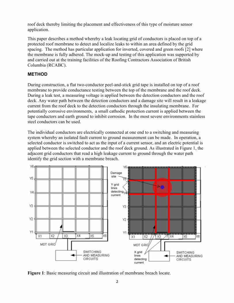
The individual conductors are electrically connected at one end to a switching and measuring
system whereby an isolated fault current to ground measurement can be made. In operation, a
selected conductor is switched to act as the input of a current sensor, and an electric potential is
applied between the selected conductor and the roof deck ground. As illustrated in Figure 1, the
adjacent grid conductors that read a high leakage current to ground through the water path
identify the grid section with a membrane breach.
Figure 1: Basic measuring circuit and illustration of membrane breach locate.
3
A moisture leakage path through the roof membrane will usually cause any selected grid
conductor to measure some level of leakage current. To avoid stray current that can create
significant error in the membrane breach location survey, all detection conductors not selected
for current measurement are connected to a special guard circuit. The guard circuit forms an
electric shield between the selected conductor and any other current leakage sites beyond the
conductors immediately adjacent to the selected conductor. This eliminates stray current errors
and makes this method feasible.
EXPERIMENTAL RESULTS
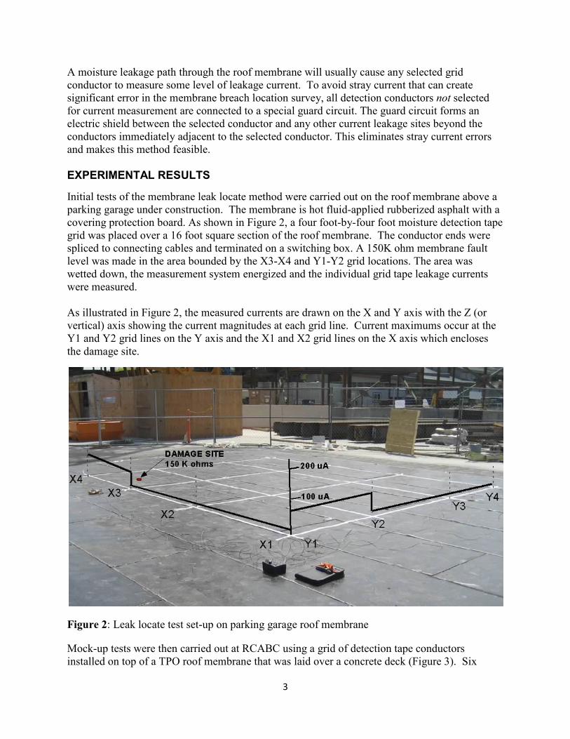
Initial tests of the membrane leak locate method were carried out on the roof membrane above a
parking garage under construction. The membrane is hot fluid-applied rubberized asphalt with a
covering protection board. As shown in Figure 2, a four foot-by-four foot moisture detection tape
grid was placed over a 16 foot square section of the roof membrane. The conductor ends were
spliced to connecting cables and terminated on a switching box. A 150K ohm membrane fault
level was made in the area bounded by the X3-X4 and Y1-Y2 grid locations. The area was
wetted down, the measurement system energized and the individual grid tape leakage currents
were measured.
As illustrated in Figure 2, the measured currents are drawn on the X and Y axis with the Z (or
vertical) axis showing the current magnitudes at each grid line. Current maximums occur at the
Y1 and Y2 grid lines on the Y axis and the X1 and X2 grid lines on the X axis which encloses
the damage site.
Figure 2: Leak locate test set-up on parking garage roof membrane
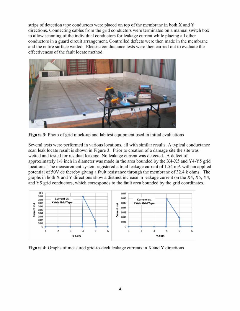
Mock-up tests were then carried out at RCABC using a grid of detection tape conductors
installed on top of a TPO roof membrane that was laid over a concrete deck (Figure 3). Six
4
strips of detection tape conductors were placed on top of the membrane in both X and Y
directions. Connecting cables from the grid conductors were terminated on a manual switch box
to allow scanning of the individual conductors for leakage current while placing all other
conductors in a guard circuit arrangement. Controlled defects were then made in the membrane
and the entire surface wetted. Electric conductance tests were then carried out to evaluate the
effectiveness of the fault locate method.
Figure 3: Photo of grid mock-up and lab test equipment used in initial evaluations
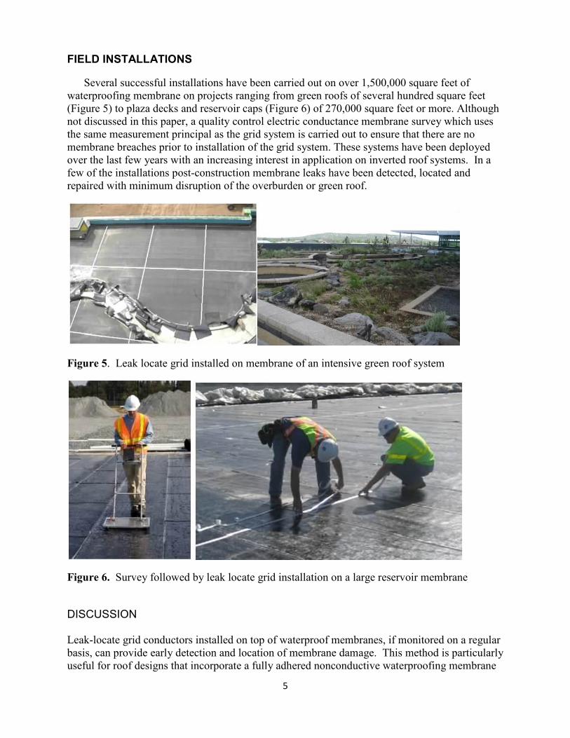
Several tests were performed in various locations, all with similar results. A typical conductance
scan leak locate result is shown in Figure 3. Prior to creation of a damage site the site was
wetted and tested for residual leakage. No leakage current was detected. A defect of
approximately 1/8 inch in diameter was made in the area bounded by the X4-X5 and Y4-Y5 grid
locations. The measurement system registered a total leakage current of 1.54 mA with an applied
potential of 50V dc thereby giving a fault resistance through the membrane of 32.4 k ohms. The
graphs in both X and Y directions show a distinct increase in leakage current on the X4, X5, Y4,
and Y5 grid conductors, which corresponds to the fault area bounded by the grid coordinates.
Figure 4: Graphs of measured grid-to-deck leakage currents in X and Y directions
5
FIELD INSTALLATIONS
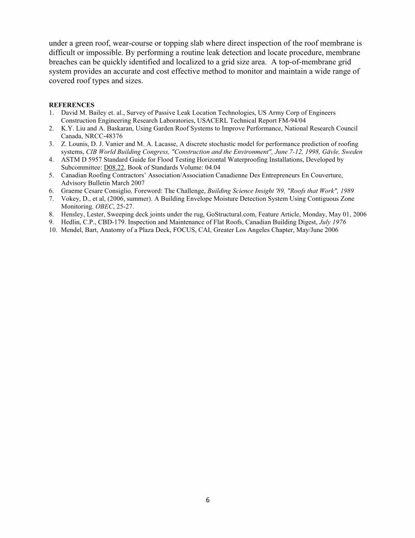
Several successful installations have been carried out on over 1,500,000 square feet of
waterproofing membrane on projects ranging from green roofs of several hundred square feet
(Figure 5) to plaza decks and reservoir caps (Figure 6) of 270,000 square feet or more. Although
not discussed in this paper, a quality control electric conductance membrane survey which uses
the same measurement principal as the grid system is carried out to ensure that there are no
membrane breaches prior to installation of the grid system. These systems have been deployed
over the last few years with an increasing interest in application on inverted roof systems. In a
few of the installations post-construction membrane leaks have been detected, located and
repaired with minimum disruption of the overburden or green roof.
Figure 5. Leak locate grid installed on membrane of an intensive green roof system
Figure 6. Survey followed by leak locate grid installation on a large reservoir membrane
DISCUSSION
Leak-locate grid conductors installed on top of waterproof membranes, if monitored on a regular
basis, can provide early detection and location of membrane damage. This method is particularly
useful for roof designs that incorporate a fully adhered nonconductive waterproofing membrane
6
under a green roof, wear-course or topping slab where direct inspection of the roof membrane is
difficult or impossible. By performing a routine leak detection and locate procedure, membrane
breaches can be quickly identified and localized to a grid size area. A top-of-membrane grid
system provides an accurate and cost effective method to monitor and maintain a wide range of
covered roof types and sizes.
REFERE�CES
1. David M. Bailey et. al., Survey of Passive Leak Location Technologies, US Army Corp of Engineers
Construction Engineering Research Laboratories, USACERL Technical Report FM-94/04
2. K.Y. Liu and A. Baskaran, Using Garden Roof Systems to Improve Performance, National Research Council
Canada, NRCC-48376
3. Z. Lounis, D. J. Vanier and M. A. Lacasse, A discrete stochastic model for performance prediction of roofing
systems, CIB World Building Congress, "Construction and the Environment", June 7-12, 1998, Gävle, Sweden
4. ASTM D 5957 Standard Guide for Flood Testing Horizontal Waterproofing Installations, Developed by
Subcommittee: D08.22, Book of Standards Volume: 04.04
5. Canadian Roofing Contractors’ Association/Association Canadienne Des Entrepreneurs En Couverture,
Advisory Bulletin March 2007
6. Graeme Cesare Consiglio, Foreword: The Challenge, Building Science Insight '89, "Roofs that Work", 1989
7. Vokey, D., et al, (2006, summer). A Building Envelope Moisture Detection System Using Contiguous Zone
Monitoring. OBEC, 25-27.
8. Hensley, Lester, Sweeping deck joints under the rug, GoStructural.com, Feature Article, Monday, May 01, 2006
9. Hedlin, C.P., CBD-179. Inspection and Maintenance of Flat Roofs, Canadian Building Digest, July 1976
10. Mendel, Bart, Anatomy of a Plaza Deck, FOCUS, CAI, Greater Los Angeles Chapter, May/June 2006
Recommended