A first generation compact microbeam radiation therapy system based oncarbon nanotube X-ray technologyM. Hadsell, J. Zhang, P. Laganis, F. Sprenger, J. Shan et al. Citation: Appl. Phys. Lett. 103, 183505 (2013); doi: 10.1063/1.4826587 View online: http://dx.doi.org/10.1063/1.4826587 View Table of Contents: http://apl.aip.org/resource/1/APPLAB/v103/i18 Published by the AIP Publishing LLC. Additional information on Appl. Phys. Lett.Journal Homepage: http://apl.aip.org/ Journal Information: http://apl.aip.org/about/about_the_journal Top downloads: http://apl.aip.org/features/most_downloaded Information for Authors: http://apl.aip.org/authors
A first generation compact microbeam radiation therapy system basedon carbon nanotube X-ray technology
M. Hadsell,1,a) J. Zhang,1,2 P. Laganis,3 F. Sprenger,3 J. Shan,1 L. Zhang,4 L. Burk,1
H. Yuan,5 S. Chang,1,2 J. Lu,1,4 and O. Zhou1,4,b)
1Department of Physics and Astronomy, University of North Carolina, Chapel Hill, North Carolina 27599,USA2Department of Radiation Oncology, University of North Carolina, Chapel Hill, North Carolina 27599, USA3XinRay Systems, Inc., 7020 Kit Creek Road, Suite 210, Research Triangle Park, North Carolina 27709, USA4Curriculum in Applied and Materials Sciences, University of North Carolina, Chapel Hill,North Carolina 27599, USA5Biomedical Research Imaging Center, University of North Carolina, Chapel Hill, North Carolina 27599, USA
(Received 5 June 2013; accepted 22 September 2013; published online 30 October 2013)
We have developed a compact microbeam radiation therapy device using carbon nanotube cathodes
to create a linear array of narrow focal line segments on a tungsten anode and a custom collimator
assembly to select a slice of the resulting wedge-shaped radiation pattern. Effective focal line
width was measured to be 131 lm, resulting in a microbeam width of �300 lm. The instantaneous
dose rate was projected to be 2 Gy/s at full-power. Peak to valley dose ratio was measured to be
>17 when a 1.4 mm microbeam separation was employed. Finally, multiple microbeams were
delivered to a mouse with beam paths verified through histology. VC 2013 AIP Publishing LLC.
[http://dx.doi.org/10.1063/1.4826587]
More than half of cancer patients in North America rely
on radiation therapy (RT) as part of their treatment plan.1
The primary goal of RT, like other cancer treatments, is to
eliminate the cancer while preventing simultaneous and
intolerable damage to the surrounding normal tissues.2
Although incredible strides to this end have recently been
made through the use of increasingly conformal techniques
and much stronger targeting, no such technique has suc-
ceeded in leaving normal tissue completely unscathed while
eradicating the targeted tumor.3 A recent modality of RT
called microbeam radiation therapy (MRT), however, has in
the past two decades shown promise in achieving complete
normal tissue sparing during the treatment of deep-seated
brain tumors in rats.4 In one of the earlier studies, it was
shown that MRT can increase the lifespan of brain tumor-
bearing rats by up to a factor of ten through total tumor abla-
tion,5 and more recently, it has also been suggested that this
technique could be used to treat neurological disease based
on its ability to create microscopic, radiosurgical brain
lesions in rats.6
The history of MRT is rooted in two research areas ini-
tially explored more than half a century ago. The purpose of
the first was to determine the morbidity of the ultra-high dose
heavy-ion pencil beams present in space expeditions.7 In these
studies, it was found that microscopically small beams
(�25 lm) could deposit doses of up to 4000 Gy without caus-
ing tissue-level damage,8 the discovery of which led to the use
of such microbeams for cell-specific radiobiological research.9
The second was the use of spatially fractionated, or GRID,
radiation therapy to treat target areas with a macroscopic,
checkerboard-like pattern of radiation.10 This technique was
initially developed before the advent of megavoltage therapy
to spare skin during the treatment of deep-seated tumors with
orthovoltage X-rays.11 More recently, single fractions of meg-
avoltage GRID therapy achieved through the use of large
sieve-type blocks or multileaf collimators (MLCs)12 have
been shown to effectively augment conventional radiotherapy,
providing the extra tumor dose necessary for the complete
clinical and pathological control of large and bulky tumors.13
MRT combines the working concepts of these two areas
of research by employing arrays of microscopically-thin
(�100 lm), planar X-ray beams that are separated by several
times their beam width.14 The resulting radiation dose distri-
bution has characteristic peaks and valleys with an extremely
high (>10) peak to valley dose ratio (PVDR).15 Retaining
this high PVDR has been shown to be essential16 to sparing
developing normal brain tissue in weaning piglets,17 duck
embryos,18 and suckling rats.19 The megavoltage photon
energies used in most conventional RT cannot be used for
MRT due to the fact that the ranges of the scattered, second-
ary charged particles created in the tissue are far too great to
preserve the microbeam pattern.20 Moreover, it has been
found that extremely large peak doses (>100 Gy) are
required in order to completely ablate the aggressive tumors
for which this technique would be best-suited.21 Obtaining
such high doses is unattainable within feasible time scales
using conventional orthovoltage X-ray tubes. This is due to
the fact that their dose rate would either be far too small in
the case of micro-focus tubes,22 or prohibitively reduced by
microbeam collimation in the case of tubes with typically
sized (between 1 mm and 10 mm) focal spots.23 As a result,
MRT has only been studied at synchrotron facilities, where
the creation of ultra-high flux, orthovoltage, and parallel
X-ray beams is readily achievable.24
The sparseness of synchrotron sources has limited the
availability of MRT research to the greater scientific commu-
nity. Partly because of this, the radiobiological reasons
a)Electronic addresses: [email protected] and [email protected])Electronic mail: [email protected]
0003-6951/2013/103(18)/183505/5/$30.00 VC 2013 AIP Publishing LLC103, 183505-1
APPLIED PHYSICS LETTERS 103, 183505 (2013)
behind this effect are still largely unknown.25 There is a clear
need to create microbeam dose distributions with a smaller
footprint at a lower cost, so as to spread and accelerate the
research on this promising therapy technique and, optimally,
to translate it to clinics for patient treatment. Here we report
a compact and high power microbeam irradiator for treat-
ment of tumor bearing small animals that is enabled by our
unique carbon nanotube (CNT) field emission X-ray array
technology.26 This device, as illustrated in Figure 1, uses a
linear array of CNT cathodes to create a line-focused X-ray
source with a long (162 mm) and narrow (0.14 mm) focal
track to deliver a higher microbeam dose rate than what is
afforded by a micro-focus point x-ray source and to provide
an improved depth dose profile during conformal radiation
delivery. Here we report the design and performance of this
compact microbeam irradiator.
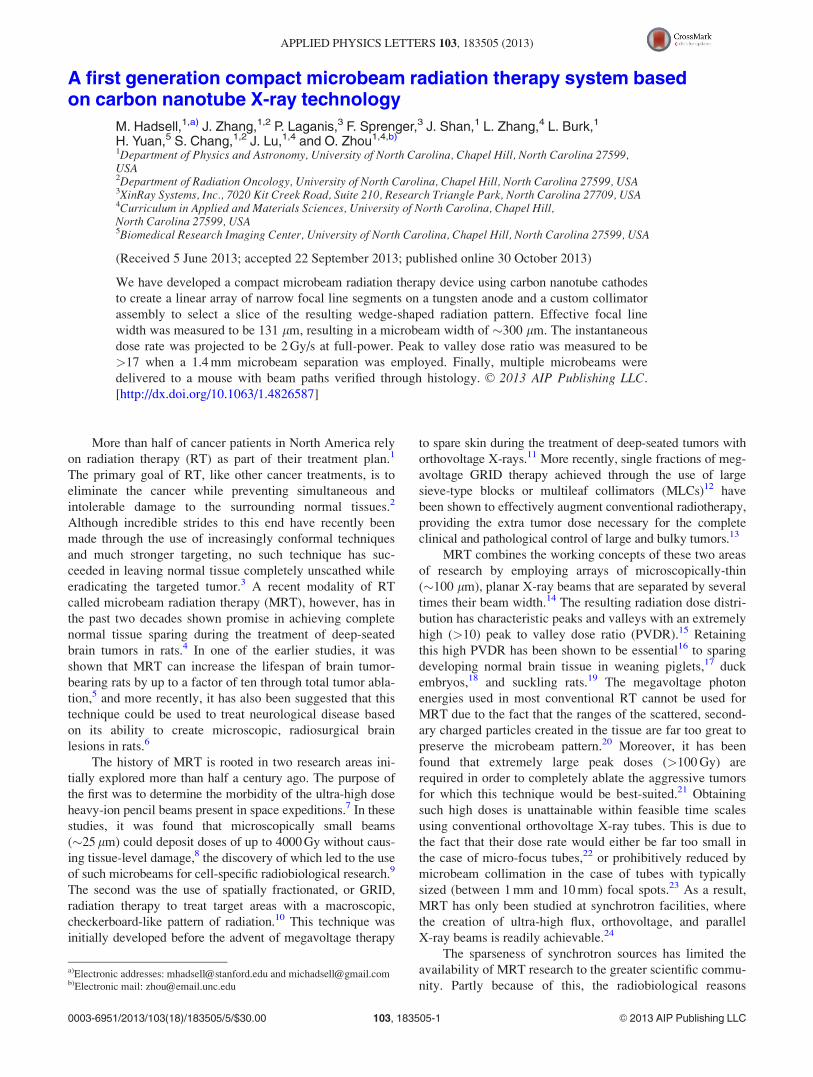
The two primary components of the CNT MRT system
that make it unique are the linear cathode array and the colli-
mator alignment system. The array, as seen in Figure 2(a), is
made up five molybdenum substrates with CNTs deposited on
each of their surfaces in a 2.5 mm � 30 mm area by the elec-
trophoretic deposition method as described previously.27 The
linear, dual-electrode focusing track and gate mesh, as illus-
trated in Figures 2(b) and 2(c), constitutes a three-component
Einzel lens whose structure was simulated by a commercial
software package (Opera 3D Vector Fields Software, Cobham
plc, Dorset, UK) to be capable of focusing the electrons
FIG. 1. (a) Photograph detailing the basic structure inside the compact
microbeam irradiator Also shown are indicators for electron trajectories
from the cathode assembly (light blue), the location of the segmented focal
line on the anode (red), X-ray photon trajectories from the anode (light
green), and the projected focal line image on the window (yellow).
(b) Diagram (as seen from cathode assembly) showing how the multiple line
segments produce microbeam paths that irradiate a sample from different
angles. For another illustration of how microbeams are created from our
source, see Figure 4(b).
FIG. 2. (a) SolidworksTM diagram showing linear array of cathodes used in
the compact MRT device. (b) Diagram illustrating the entire cathode assem-
bly and the linear focusing track. (c) Cross section through the assembly
showing the internal components and the focusing geometry used.
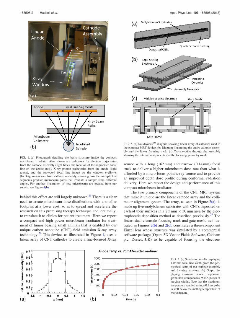
FIG. 3. (a) Simulation results displaying
1.02 mm focal line width given the geo-
metrical setup of our cathode assembly
and focusing structure. (b) Graph dis-
playing maximum anode temperature
given five simultaneous 75 mA pulses of
varying widths. Note that the maximum
temperature reached using a 0.1 ms pulse
is well below the melting temperature of
molybdenum.
183505-2 Hadsell et al. Appl. Phys. Lett. 103, 183505 (2013)
extracted from each cathode into a 1.02 mm � 30 mm focal
line segment on the anode, as illustrated in Figure 3(a).28 The
anode itself is made up of a 17 mm� 25 mm� 222 mm block
of molybdenum whose front 25 mm � 222 mm surface was
sputtered with a 200lm layer of tungsten and mirror finished
for ideal and uniform X-ray production. This anode was simu-
lated using AnsysVR
Finite Element Analysis software (Ansys,
Canonsburg, PA) to be able to withstand up to 75 mA of cur-
rent per focal line segment in short pulses of 0.1 s without
reaching either the melting point of the tungsten (3683 K) or
the molybdenum (2890 K), as plotted in Figure 3(b).29
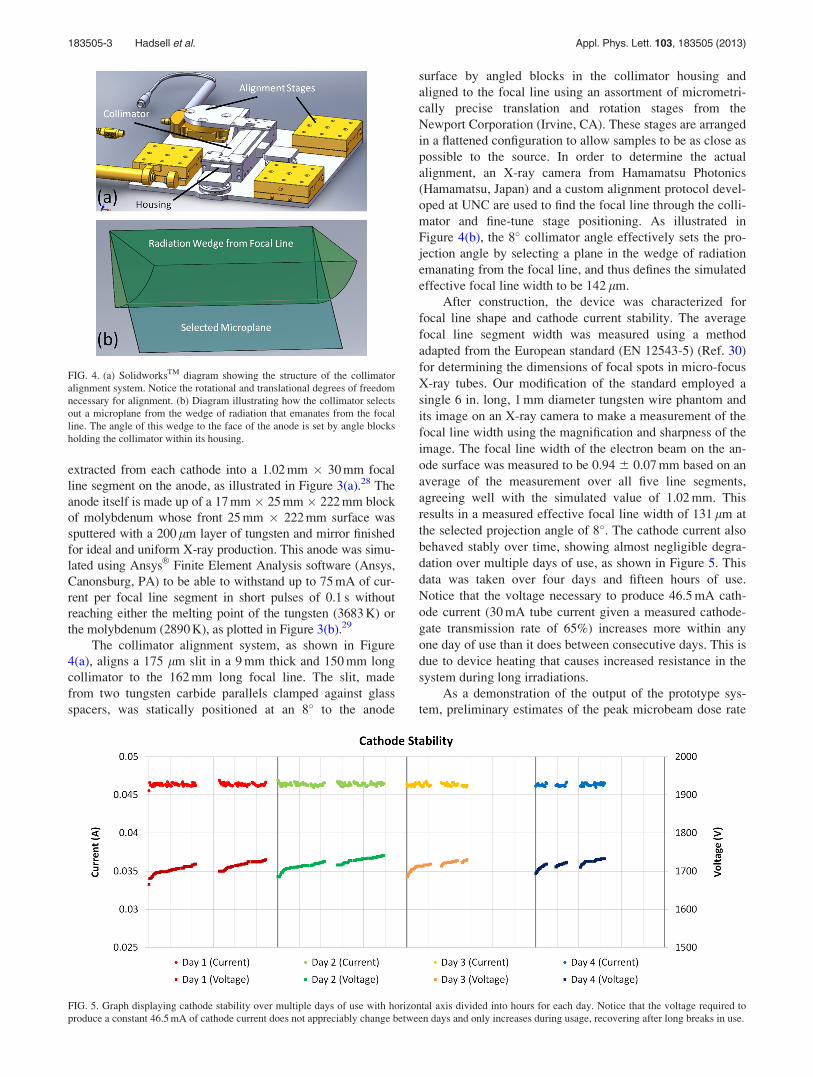
The collimator alignment system, as shown in Figure
4(a), aligns a 175 lm slit in a 9 mm thick and 150 mm long
collimator to the 162 mm long focal line. The slit, made
from two tungsten carbide parallels clamped against glass
spacers, was statically positioned at an 8� to the anode
surface by angled blocks in the collimator housing and
aligned to the focal line using an assortment of micrometri-
cally precise translation and rotation stages from the
Newport Corporation (Irvine, CA). These stages are arranged
in a flattened configuration to allow samples to be as close as
possible to the source. In order to determine the actual
alignment, an X-ray camera from Hamamatsu Photonics
(Hamamatsu, Japan) and a custom alignment protocol devel-
oped at UNC are used to find the focal line through the colli-
mator and fine-tune stage positioning. As illustrated in
Figure 4(b), the 8� collimator angle effectively sets the pro-
jection angle by selecting a plane in the wedge of radiation
emanating from the focal line, and thus defines the simulated
effective focal line width to be 142 lm.
After construction, the device was characterized for
focal line shape and cathode current stability. The average
focal line segment width was measured using a method
adapted from the European standard (EN 12543-5) (Ref. 30)
for determining the dimensions of focal spots in micro-focus
X-ray tubes. Our modification of the standard employed a
single 6 in. long, 1 mm diameter tungsten wire phantom and
its image on an X-ray camera to make a measurement of the
focal line width using the magnification and sharpness of the
image. The focal line width of the electron beam on the an-
ode surface was measured to be 0.94 6 0.07 mm based on an
average of the measurement over all five line segments,
agreeing well with the simulated value of 1.02 mm. This
results in a measured effective focal line width of 131 lm at
the selected projection angle of 8�. The cathode current also
behaved stably over time, showing almost negligible degra-
dation over multiple days of use, as shown in Figure 5. This
data was taken over four days and fifteen hours of use.
Notice that the voltage necessary to produce 46.5 mA cath-
ode current (30 mA tube current given a measured cathode-
gate transmission rate of 65%) increases more within any
one day of use than it does between consecutive days. This is
due to device heating that causes increased resistance in the
system during long irradiations.
As a demonstration of the output of the prototype sys-
tem, preliminary estimates of the peak microbeam dose rate
FIG. 4. (a) SolidworksTM diagram showing the structure of the collimator
alignment system. Notice the rotational and translational degrees of freedom
necessary for alignment. (b) Diagram illustrating how the collimator selects
out a microplane from the wedge of radiation that emanates from the focal
line. The angle of this wedge to the face of the anode is set by angle blocks
holding the collimator within its housing.
FIG. 5. Graph displaying cathode stability over multiple days of use with horizontal axis divided into hours for each day. Notice that the voltage required to
produce a constant 46.5 mA of cathode current does not appreciably change between days and only increases during usage, recovering after long breaks in use.
183505-3 Hadsell et al. Appl. Phys. Lett. 103, 183505 (2013)

and PVDR of a sample microbeam pattern were attained.
Gafchromic EBT2 film (Ashland Advanced Materials,
Covington, KY) was adopted for these initial measurements
of the CNT microbeam radiation source due to its quoted
dose range between 0 and 40 Gy in the green channel, high
spatial resolution, and energy independence from about
60 keV into the MeV range.31 For our microbeam study, the
film calibration curve was created using the 6 MV X-ray
beam from a clinical CyberknifeVR
(Accuray, Sunnyvale, CA)
source installed in the Radiation Oncology Department of
the North Carolina Cancer Hospital. All dose film scans
were performed according to the recommendations of
Ashland, Inc., using a Perfection V700 flatbed scanner
(Epson America, Long Beach, CA).32
In order to estimate the maximum peak entrance dose rate
that a small animal placed in the treatment would experience,
a strip of film was placed directly beneath the collimator align-
ment system, as shown in Figure 6(a). The compact MRT de-
vice was operated at a constant anode voltage of 160 kV, while
given a tube current of 70 mA from a single cathode driven at
a 1 ms pulse width and 5% duty cycle for approximately
8 min. As can be seen in Figure 6(b), the peak microbeam
dose on the film was measured to be 10.4 6 1.5 Gy with the
full width at half maximum of the microbeam created being
260 lm. Based on this measurement, the device should be ca-
pable of a �2 Gy/s in-pulse dose rate with all five cathodes
turned on simultaneously.
In addition, a sample PVDR was measured by irradiat-
ing a film sandwiched between two 0.5 in. slabs of tissue-
equivalent plastic with four separate microbeams created by
successively translating the sample stage by 1.4 mm every
15 min for a total of 60 min. For this experiment, the device
was operated at an anode voltage of 156 kV, while given a
tube current of 14 mA from two cathodes simultaneously run
at a 10% duty cycle and 1 ms pulse width. The results, as can
be seen in Figure 7(a), yielded a PVDR of >17 and a slightly
wider beam width of 315 lm. This was to be expected
because the film was placed slightly further from the colli-
mator due to the plastic phantom. Based on this measure-
ment, we conclude that our compact CNT-MRT device can
achieve relative dose distributions in small animals that are
similar to those experimented with at synchrotron facilities.
We have also gone on to verify the capability of the sys-
tem to deliver MRT in mice. In one preliminary study, a
mouse pup (postnatal day 12, P12) was immobilized using a
custom-made stereotactic head frame and nose cone, anesthe-
tized using an isoflurane vaporizer from SurgiVetVR
(Smiths
Medical, Norwell, MA), and monitored with the BioVetVR
sys-
tem (M2M Imaging, Cleveland, OH). Five 300 lm wide
microbeams with a 13 Gy peak entrance dose spaced at
900 lm center to center were delivered to the cerebellum dur-
ing a 50 min irradiation. The animal was sacrificed 4 h after
irradiation. Afterwards, its brain was removed, fixed in paraf-
fin, sliced, and stained for the c-H2AX foci, a standard marker
used to examine DNA damage and subsequent repair of DNA
double strand breaks.33 Figure 7(b) shows the c-H2AX staining
on the P12 mouse brain, clearly indicating radiation-induced
DNA damage along the microbeam path. With this
animal model and immunohistological technique, it is shown
FIG. 6. (a) SolidworksTM cross section
of the entire device design displaying
the target location beneath the anode,
X-ray window, and collimator assem-
blies. (b) Sample irradiated film and
beam profile displaying the peak dose
achieved in 8 min of irradiation and
width of the microbeam created.
FIG. 7. (a) Irradiated film and dose profile displaying our peak to valley
dose ratio given a center to center separation of 1.4 mm between the
microbeams. (The intensity variation seen here is due to slight non-
uniformity in focal line position and collimator transmission under tube
heating during continual use.) (b) Histological image of microbeam DNA
damage in a mouse brain. Cell staining was done with c-H2AX labeling, and
the peak entrance dose given was 13 Gy per microbeam.
183505-4 Hadsell et al. Appl. Phys. Lett. 103, 183505 (2013)
here that our device is capable of delivering prescribed
microbeam radiation dose in vivo and enabling further explo-
ration of the effects of microbeam radiation in live animals.
In conclusion, a compact MRT device for radiobiologi-
cal, mechanistic studies in small animals has been created.
Using CNT X-ray technology, this device employs a long
focal line to distribute heat across a stationary anode, which
allows the generation of high flux X-radiation from the nar-
row line. We have developed a collimator and alignment sys-
tem to shape the high flux from the focal line into a single
�300 lm wide microplanar beam. We have demonstrated
that this system is capable of producing MRT dose distribu-
tions in phantoms and mice comparable to those achieved
with synchrotron based MRT systems, and demonstrated the
long-term stability needed for mechanistic studies. Using
this device, we hope to bring MRT research to the greater
scientific community and possibly provide the groundwork
for the creation of a clinical scale device.
The authors would like to thank Dr. Guohua Cao for
helpful discussions during preliminary device design and
Christy Inscoe, Pavel Chtcheprov, Rachel Ger, and Torsten
Schreiber for their help with construction, testing, and run-
ning of the device. The authors would also like to thank Dr.
Timothy Gershon for supplying the mouse pup for experi-
mentation and Andrew Crowther for performing the histo-
logical analysis. This work was supported by the Carolina
Center of Cancer Nanotechnology Excellence (Grant No.
U54-CA151652) and the National Institute of Health Grand
Opportunities “GO” program (Grant No. RC2-CA148487).
1D. R. Smart, Physician Characteristics and Distribution in the US 2010(American Medical Association, Chicago, IL, 2009).
2E. J. Hall and A. J. Giaccia, Radiobiology for the Radiologist, 6th ed.
(Lippincott Williams and Wilkins, Philadelphia, PA, 2006).3J. Van Dyk, “The modern technology of radiation oncology,” in ACompendium for Medical Physicists and Radiation Oncologists (Medical
Physics Publishing, Madison, WI, 2005).4J. A. Laissue, G. Geiser, P. O. Spanne, F. A. Dilmanian, J.-O. Gebbers, M.
Geiser, X.-Y. Wu, M. S. Makar, P. L. Micca, M. M. Nawrocky et al., Int.
J. Cancer 78(5), 654 (1998); E. Brauer-Krisch, R. Serduc, E. A. Siegbahn,
G. Le Duc, Y. Prezado, A. Bravin, H. Blattmann, and J. A. Laissue, Mutat
Res. 704(1–3), 160 (2010).5F. A. Dilmanian, T. M. Button, G. Le Duc, N. Zhong, L. A. Pena, J. A. L.
Smith, S. R. Martinez, T. Bacarian, J. Tammam, B. Ren et al., J. Neuro-
Oncol. 4(1), 26 (2002).6P. Romanelli and A. Bravin, Neurol. Res. 33(8), 825 (2011).7H. J. Curtis, Radiat. Res. Suppl. 7, 250 (1967).8W. Zeman, H. J. Curtis, and C. P. Baker, Radiat. Res. 15(4), 496 (1961).9K. M. Prise and G. Schettino, Radiat. Prot. Dosim. 143(2–4), 335 (2011).
10A. S. Meigooni, U. Malik, H. Zhang, S. A. Dini, N. J. Meigooni, K.
Komanduri, and M. Mohiuddin, Iran. J. Radiat. Res. 2(4), 167 (2005).11W. V. Tenzel, Radiology 59(3), 399 (1952).12G. Neuner, M. M. Mohiuddin, N. V. Walde, O. Goloubeva, J. Ha, C. X. Yu,
and W. F. Regine, Int. J. Radiat. Oncol., Biol., Phys. 82(5), 1642 (2012).
13M. Mohiuddin, M. Fujita, W. F. Regine, A. S. Megooni, G. S. Ibbott, and
M. M. Ahmed, Int. J. Radiat. Oncol., Biol., Phys. 45(3), 721 (1999); J. A.
Penagaricano, R. Griffin, P. Corry, E. Moros, Y. Yan, and V.
Ratanatharathorn, J. Ark. Med. Soc. 105(11), 263 (2009).14D. N. Slatkin, P. Spanne, F. A. Dilmanian, and M. Sandborg, Med. Phys.
19(6), 1395 (1992).15M. De Felici, R. Felici, M. S. del Rio, C. Ferrero, T. Bacarian, and F. A.
Dilmanian, Med. Phys. 32(8), 2455 (2005); J. C. Crosbie, I. Svalbe, S. M.
Midgley, N. Yagi, P. A. Rogers, and R. A. Lewis, Phys. Med. Biol.
53(23), 6861 (2008).16P. Regnard, G. Le Duc, E. Brauer-Krisch, I. Tropres, E. A. Siegbahn, A.
Kusak, C. Clair, H. Bernard, D. Dallery, J. A. Laissue et al., Phys. Med.
Biol. 53(4), 861 (2008).17J. A. Laissue, H. Blattmann, M. D. Michiel, D. N. Slatkin, N. Lyubimova,
R. Guzman, W. Zimmermann, S. Birrer, T. Bley, P. Kircher et al., Proc.
SPIE 4508, 65 (2001).18F. A. Dilmanian, G. M. Morris, G. Le Duc, X. Huang, B. Ren, T.
Bacarian, J. C. Allen, J. Kalef-Ezra, I. Orion, E. M. Rosen et al., Cell.
Mol. Biol. (Paris) 47(3), 485 (2001).19J. A. Laissue, N. Lyubimova, H.-P. Wagner, D. W. Archer, D. N. Slatkin,
M. Di Michiel, C. Nemoz, M. Renier, E. Brauer, P. O. Spanne et al., Proc.
SPIE 3770, 38 (1999).20E. A. Siegbahn, J. Stepanek, E. Bra€uuer-Krisch, and A. Bravin, Med.
Phys. 33(9), 3248 (2006).21D. J. Anschel, A. Bravin, and P. Romanelli, Neurosurg. Rev. 34(2), 133
(2011).22F. Verhaegen, P. Granton, and E. Tryggestad, Phys. Med. Biol. 56(12),
R55 (2011).23K. Huang, K. Yan, T. Podder, Y. Hu, and Y. Yu, “Feasibility Analysis On
Converting Conventional Orthovoltage Biological Irradiator to a Micro-
Beam Array for Small Animal/cell Irradiation,” paper presented at the
AAPM Annual Meeting, Anaheim, CA, 2009 (unpublished).24E. Bra€uer-Krisch, H. Requardt, T. Brochard, G. Berruyer, M. Renier, J. A.
Laissue, and A. Bravin, Rev. Sci. Instrum. 80(7), 074301 (2009); H.
Nettelbeck, G. J. Takacs, M. L. F. Lerch, and A. B. Rosenfeld, Med. Phys.
36(2), 447 (2009).25J. C. Crosbie, R. L. Anderson, K. Rothkamm, C. M. Restall, L. Cann, S.
Ruwanpura, S. Meachem, N. Yagi, I. Svalbe, R. A. Lewis et al., Int. J.
Radiat. Oncol., Biol., Phys. 77(3), 886 (2010); A. Bouchet, B. Lemasson,
G. Le Duc, C. Maisin, E. Brauer-Krisch, E. A. Siegbahn, L. Renaud, E.
Khalil, C. Remy, C. Poillot et al., Int. J. Radiat. Oncol., Biol., Phys. 78(5),
1503 (2010).26O. Zhou and X. Calderon-Colon, in Carbon Nanotube and Related Field
Emitters, edited by Y. Saito (John Wiley and Sons, Hoboken, NJ, 2010),
p. 417; G. Cao, Y. Z. Lee, R. Peng, Z. Liu, R. Rajaram, X. Calderon-
Colon, L. An, P. Wang, T. Phan, and S. Sultana et al., Phys. Med. Biol.
54(8), 2323 (2009); X. Qian, A. Tucker, E. Gidcumb, J. Shan, G. Yang, X.
Calderon-Colon, S. Sultana, J. Lu, O. Zhou, and D. Spronk et al., Med.
Phys. 39(4), 2090 (2012).27X. Calderon-Colon, H. Geng, B. Gao, L. An, G. Cao, and O. Zhou,
Nanotechnology 20(32), 325707 (2009).28S. Sultana, X. Calder�on-Col�on, G. Cao, O. Zhou, and J. Lu, Proc. SPIE
7622, 76225G (2010); J. Zhang, M. Hadsell, J. Lu, O. Zhou, and S. Chang,
Proc. SPIE 8668, 86685C (2013).29J. Shan, O. Zhou, and J. Lu, Proc. SPIE 8313, 83130O (2012).30Characteristics of Focal Spots in Industrial X-ray Systems for use in Non-
Destructive Testing (European Committee for Standardization, Brussels,
1999), Vol. EN 12543–5.31Gafchromic EBT2: Self-Developing Film for Radiotherapy Dosimetry
(International Specialty Products, Wayne, NJ, 2010).32D. Lewis, Using Radiochromic Film: Tips and Techniques (International
Specialty Products, Wayne, NJ, 2010).33L. J. Kuo and L.-X. Yang, In Vivo 22(3), 305 (2008).
183505-5 Hadsell et al. Appl. Phys. Lett. 103, 183505 (2013)
Recommended